JFE_BWMS说明资料20110420(PDF)[1]
servomex4100培训手册

• 传感器温度 Cell Temperature
–Pm1158 (氧控制模块不加热); 典型 30oC –范围 5 ~ 70oC –S4100995A (氧纯度模块加热); 设为 55oC –范围 50 ~ 60oC
• 压力传感器输出(仅氧纯度模块) Cell Pressure
–典型 15psia –范围 5 ~ 25psia
卡槽前框架
1 4 3 2
电源入口 机架
传感器信号连接器
4 3 2 1
变压器
多路转换器 (MUX)板 传感器电源连接器 主板
PDF 文件使用 "pdfFactory Pro" 试用版本创建
外部风扇装配图
风向
风扇 隔离板
电源连接 主板
过滤网(可更换)
过滤器网罩
PDF 文件使用 "pdfFactory Pro" 试用版本创建
电磁阀 #1 电磁阀 #2
PL5
主板
开关电源
SK12
外部通道E1, E2
PL1
终端接线板 mA/继电器 板 A(选配) 终端接线板 mA/继电器 板 B(选配) 终端接线板 mA/继电器 板 B(选配) 终端接线板
PL6
PL3
传感器接口 板(SIB) 微处理器板
SK2 SK3
SK5 SK22 SK6 SK7
PDF 文件使用 "pdfFactory Pro" 试用版本创建
人机界面
方向键(上,下,左,右) 选择或输入文字及数字等
ENTER键 确认或执行
MEASURE键 返回测量显示状态
MENU键 QUIT键 显示顶层菜单 返回上一级菜单
EDIT键 显示编辑功能的快捷键
ifm电子流量计器产品说明书
Resolution
Set point SP
Reset point rP
Measuring dynamics
Frequency end point, FEP
Frequency at the end point FRP
[Hz]
In steps of
0.2...10 gpm 0...12 gpm
0.1 gpm 0.1...10 gpm 0...9.9 gpm
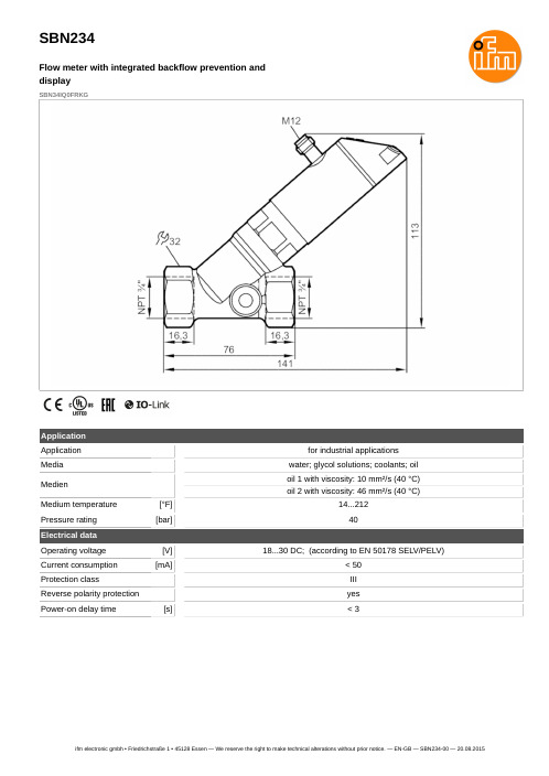
stainless steel (1.4401 / 316); stainless steel (1.4404 / 316L); brass (2.0371); brass chemically nickel-plated; PPS; O-ring: FKM
Process connection
threaded connection 3/4 NPT
hysteresis / window; normally open / normally closed; switching logic; current output; medium selection; damping for the switching output / analogue output; display can be rotated and switched off; standard unit of measurement; process value colour
SBN234
Flow meter with integrated backflow prevention and display
SBN34IQ0FRKG
Connection
OUT1: OUT2: -
BK = BN = BU = WH =
海南曼姆全系产品介绍说明书
Heinemann®GJ1P Series Circuit BreakersDESCRIPTIONOptional Low-Voltage Shunt for Current MeteringEaton Corporation’s Cutler-Hammer series of Heinemann GJ1P breakers offer high quality circuit protection for DC applications from 100 to 1200 Amperes.Their precisely tailored time delays and ability to interrupt high currents makes them ideally suited for critical applications. On overloads exceeding 1000 – 1400% of rating, there is no intentional time delay and the breaker interrupts currents of as much as 25,000 A at 65V DC.An optional shunt (25 or 50millivolt full scale) permits metering of current. Since the shunt output is low voltage,light-gauge wiring can be used from shunt to meter.Indication may be displayed inpercent, watts, safe/danger or other dial calibrations. In addition, the busbar is available in two versions:Standard Size and Reduced Size. Contact your Eaton Sales Representative for more information.Precision Current Equalization (PCE) Circuit BreakersGJ1P breakers rated 250 to1200 A are built in parallel construction. Conventional parallel pole breakers can experience uneven current distribution because of variations in internalresistances. This condition can result in nuisance tripping since the higher current in one parallel branch has the same effect as an overload on the sensing element in that branch. Proprietary Precision Current Equalization (PCE)circuit breakers, on the other hand, allow for differences in internal resistances byautomatically distributing the current equally through the parallel current sensing elements, minimizing the danger of nuisance tripping.The UL listed series GJ1P (UL489) models are available in a choice of fast, medium or slow response times to accurately match load conditions. They can be ordered in “series trip ”, “mid-trip ” and “switch only ”constructions and are available front- or back-mounted, front- or back-connected, with optional auxiliary switches for signaling.HYDRAULIC-MAGNETIC BENEFITSThe magnetic/hydraulic load-sensing and time delaymechanisms used in GJ1P breakers are insensitive to changes in ambient or enclosure temperature.Therefore, GJ1P circuitbreakers are suited for service conditions encountered in telecommunications,transportation, air conditioning and other outdoor or “heat-loaded ” equipment.SPECIFICATIONSStandard Current Ratings:100, 125, 150, 175, 200, 225,250, 300, 350, 400, 450, 500,600, 700, 800, 900, 1000,1100, 1200 A.Standard Maximum Voltages:160V DC up to 700A65V DC from 701 to 1200A Breakers will be labeled with standard maximum (UL) voltage unless otherwise specified.Special Current Ratings:Any integral rating between 100and 1200 A DC. Consult factory for ordering information and metering shunt restrictions.Interrupting Capacities:UL Listed:10,000 A @ 160V DC 25,000 A @ 65V DC Non-UL:14,000 A @ 160V DC.Operating Temperature Range:-40°C to +85°C.Approximate Weight:1-pole (100-225A) 1.13kg (2.5lbs)2-pole (250-400A) 2.27kg (5lbs)3-pole (450-700A) 3.40kg (7.5lbs)4-pole (701-800A) 4.54kg (10lbs)5-pole (801-1000A) 5.67kg (12.5lbs)6-pole (1001-1200A) 6.80kg (15lbs)Weight may vary based on shunt and busbar.APPROVALSUL Listing:GJ1P breakers are UL listed per UL489. For CSA certification,consult application engineering.Description . . . . . . . . . . . . . .2Specifications . . . . . . . . . . . .2Approvals . . . . . . . . . . . . . . .2Time Delay Characteristics . . .3Dimensions . . . . . . . . . . . .4-5How to Order . . . . . . . . . . .6-7Additional Products. . . . . . . . .8TABLE OF CONTENTS PageHEINEMANN ®CIRCUIT BREAKERSGJ1P Series Circuit Breakers(100-1200 Amperes DC)2Heinemann is a registered trademark of the Eaton Corporation, Commercial Controls Business Unit.100150.01.001.1110100100010,000200300400500600700800900100011001200125C u rv e 1C u rv e 2C u rv e 3Current – Percent of Ampere RatingT r i p T i m e – S e c o n d sDC CURVES100150.01.001.1110100100010,000200300400500600700800900100011001200125Current – Percent of Ampere RatingT r i p T i m e – S e c o n d sINSTANT DELAY DC CURVE PPERCENT OF RATED CURRENT VS. TRIP DELAY AT 25ºCTIME DELAYCHARACTERISTICSTime delay, in all models,is inversely proportional to the magnitude of the overload, adjusting automatically to limit transient power to the load. On overloads exceeding 1,000 –1,400%, the circuit breaker trips without any deliberately imposed delay.Curve 1.Standard time delayis furnished unlessanother optional delay is specified. It is thepreferred characteristic for use where the load is composed of both resistive and inductive components.Curve 2.Medium time delayis for general usein mixed (inductive and resistive) circuits where the breaker rating is matched to the current carrying capacity of the mains.Curve 3.Short time delaypermits a very brief delay period before tripping.Curve P .Non-time delay breakersare available forapplications which cannot tolerate even brief transient overloads.These breakers have no time delay mechanism other than that imposed by the coil self-inductance and the inertia of the mechanism.Tripping specificationsThe time delay curves depict breaker response time vs. percent of rated load with no preloading.The function is plotted at an ambient temperature of 77°F (25°C) with the breaker in a vertical or wall-mounted position.Series GJ1P circuitbreakers will carry 100%of rated load continuously.Both time delay and non-time delay breakers may trip between 101%and 125% of rated load,and must trip at 125%and above.3% (sec)Delay 100%125%200%400%600%800%1000%Delay Max.1no trip 1100150206 1.7.065Delay Min.1no trip 110224 1.1.01.008Delay Max.2no trip 110153.8.28.055Delay Min.2no trip 12 2.5.5.18.01.008Delay Max.3no trip 10.8.19.08.047.038Delay Min.3no trip.44.13.03.015.01.008STANDARD FRONT-CONNECTED CONSTRUCTIONWire Range #6 to 250 MCM74.59(2.938)76.20(3.000)Aux. Terminals, Male Type Molex 02-09-2101, Model 1190-T(See Illustrations for Combinations)Shunt Terminals, Female TypeMolex 02-09-1101, Model 1189-T37.69(1.484)42.84(1.687)0.99 (0.390)71.42(2.812)#10-32 Inserts (4 Places)38.10(1.500)19.05(0.750)19.05(0.750)6.35 ± 0.38(0.250 ± 0.156)6.35 ± 0.38(0.250 ± 0.156)Panel Mounting Hole Distance for #10-32LINELOAD 75.38(2.968)5.53(0.218)59.91(2.359)32.13(1.266)5.53(0.219)“D ” Type Terminals as Shown180.97(7.125)41.27(1.625)4.74(0.188)58.67(2.313)41.27(1.625)41.27(1.625)263.52(10.375)29.36(1.156)7.14(0.281)78.56(3.094)59.13(2.328)28°±5°32°±5°ONOFFSee Optional Terminal ConfigurationWire Range #6to 250 MCM41.27(1.625)36.49(1.437)38.10(1.500)100 – 22 A250 – 400Width dimensions are as follows:100 – 225 38.1 (1.5)250 – 400 A 76.2 (3.0)450 – 700 A 114.3 (4.5)701 – 800A 142.4 (6.0)801 – 1000A 190.5 (7.5)1001 – 1200A228.6 (9.0)28.95(1.141)46.40(1.828)22.22(0.875)Fastener Mounted ThisSide of Bus Plate,Terminals are Front-Connected and Unit is Rear-Mounted.Fastener Mounted This Side of Bus Plate, Terminalsare Back-Connected and Unit is Panel-Mounted.60.32(2.375)7.92(0.312)3/8-16UNC -2B (4 per Unit)38.10(1.500)225.43 (8.875)Center to CenterOptional Terminal ConfigurationsHEINEMANN ®CIRCUIT BREAKERSGJ1P Series Circuit BreakersDIMENSIONSDimensions are given here only as a preliminary guide to specifying. Final engineeringdrawings should be made from the latest Heinemann drawings. Contact Customer Service Center.Tolerance:±0.79 (0.031) except where noted. For metric threads, contact Customer Service Center.DIMENSIONS APPROXIMATE IN MM (INCHES)431.75(1.250) Min.41.65(1.641) Max.19.05(0.750)7.51(0.297)7.51(0.297)7.51(0.297)16.66(0.656)Typ.29.36(1.156)29.36(1.156)48.41(1.906)48.41(1.906)67.46(2.656)67.46(2.656)38.10(1.500)38.10(1.500)38.10(1.500)38.10(1.500)19.05(0.750)19.05(0.750)19.05(0.750)22.23(0.875) Min.321.31(12.65) Max.78.96(3.109)Min. Typ.5.15(0.203)Dia. Typ.C100 – 225 A Ratings 226 – 400 A Ratings401 – 700 150A RatingsBA106.75(4.203)Typ.C LC L C L FRONT MOUNTING PANEL AND SUPPORT BRACKET115.08(4.531)76.98(3.031)38.1(1.500)38.1(1.500)71.42(2.912)5.94(0.234)Ref.5.15(0.203)Typ. Dia.65.02(2.562)59.13(2.328)(3-Pole)3PoleC L C L C L Holes Required When Breaker Is Front-Mounted2Pole1PoleAB C (2-Pole)(1-Pole)38.88(1.531)19.43(0.765)Mounting kits containing clips, brackets and necessary hardware and instructions are available (consult factory).009-18234 100 – 225 A 1.5 (1-pole wide)009-18235 250 – 400 A 3 (2-pole wide)009-18232 450 – 700 A 4.5 (3-pole wide)For 701-1200A devices, contact your Eaton Sales Representative for mounting kit part numbers.See Step (2)See Step (5)BACK MOUNTING CIRCUIT BREAKERBack mounting circuit breaker mounting instructions 1. Position circuit breaker to support brackets.2. Place mounting bracket in recess on front top portion of circuit breaker.3. Install four (4) #10-32 by 3-1/4" long screws through holes in mounting bracket and support structure.4. Install lock washer and nut on each of the screws and tighten.5. Place mounting bracket on front lower portion of circuit breaker.6. Install two (2) #10-32 by 5/8" screws through holes in mounting bracket and support structure.7. Repeat step 4.5DIMENSIONS APPROXIMATE IN MM (INCHES)NOTE: Standard size busbar is shown above. For the reduced size busbar, contact your Eaton Sales Representative for mounting dimensions.Series PrefixGJ1PSwitch (No Coil)Series Trip w/SPDT Aux. SwitchSeries Trip Series Trip and Mid-Trip Series Trip, Mid-Trip and SPST Alarm SwitchTerminal Location Back FrontInternal Circuit Metering ShuntNo Shunts Metering Shunt Metering ShuntB HCodeLocationInternal CircuitCodeDescriptionShuntCode—25mV 50mVP M N0-2-3-98-99-Series Prefix GJ1PTerminal LocationBInternal Circuit3-Metering ShuntPAdd each appropriate Number or Letter …HEINEMANN ®CIRCUIT BREAKERSGJ1P Series Circuit BreakersHOW TO ORDER — Series GJ1PTo determine your Complete Catalog Number , you must start with appropriate Series Prefix and add the appropriate Code Letters and/or Numbers as in the example below:SELECTION TABLE61Multi-pole construction – Consult factory.An auxiliary switch, if supplied, will be located in the right pole space. If the auxiliary switch is supplied in a breaker which has a metering shunt, it will be single-pole single throw (SPST). The single-pole double throw (SPDT) auxiliary switch can be supplied only in a breaker without a metering shunt.2Cannot be used on breaker containing metering shunt.3Only for breakers rated in excess of 250 A. Breakers up to 250 A without meteringshunt are available as standard GJ1 type breakers. Please consult Series GJ catalog.MarketUL-489TerminalsSolderless Connector Bus Bar ConnectionStandard Current Ratings 1AmpereTrip Curve 1123P0 – 1200(Add 0 before amp rating if less than 1000A.Example: 0700)-01-02-03-0PDescriptionCodeDEDUStandardCodeCurveCodeComplete Catalog Number: GJ1PB3-PEDU0700-02Terminal ConfigurationEUS/European ApprovalDUStandard Current Ratings 10700Trip Curves 1-024Add 0 before amp rating if less than 1000. For example: a 700A rating would bedesignated as 0700.The width of the breaker is determined by the current rating:100 – 225 A 1.5” (1-pole wide)250 – 400 A 3” (2-pole wide)450 – 700 A 4.5” (3-pole wide)701 – 800A 6” (4-pole wide)801 – 1000A 7.5” (5-pole wide)1001 – 1200A 9” (6-pole wide)5See page 3 for time delay characteristics and trip curve information.7© 2001 Eaton Corporation All Rights Reserved Printed in USAForm No. BR5401SE0002A / CSS 65322June 2001Commercial ControlsFor the Widest Selection of Circuit Protection, from 0.01 to 1200 Amperes, Look to Eaton.。
JFC-11说明书-2010(1)
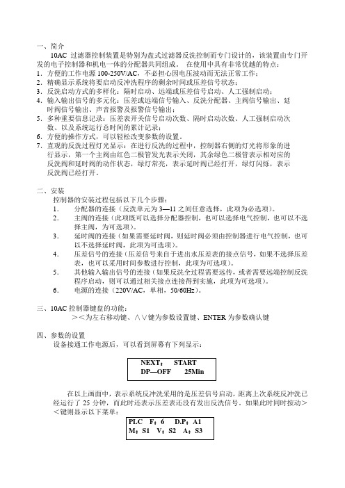
一、简介10AC过滤器控制装置是特别为盘式过滤器反洗控制而专门设计的,该装置由专门开发的电子控制器和机电一体的分配器共同组成。
在使用中具有非常优越的特点:1.方便的工作电源100-250V/AC,不必担心因电压波动而无法正常工作;2.精确显示系统将要启动反冲洗程序的剩余时间或压差信号状态;3.反洗启动方式的多样化:隔时启动、远端或压差信号启动、人工强制启动;4.输入输出信号的多元化:压差或远端信号输入、反洗分配器、主阀信号输出、延时阀信号输出、声音报警及报警信号输出;5.多种重要信息记录:压差表开关信号启动次数、隔时启动次数、人工强制启动次数、以及系统运行总时间的累计记录;6.方便的操作方式,可以轻松改变参数的设置。
7.直观的反洗过程灯光显示:在进行反洗的过程中,控制器右侧的灯光将形象的进行显示,第一个主阀由红色二极管发光表示关闭,其余绿色二极管表示相对应的反洗阀和延时阀的动作状态,绿灯常亮,表示延时阀已经打开,绿灯闪烁,表示反洗阀已经打开。
二、安装控制器的安装过程包括以下几个步骤:1.分配器的连接(反洗单元为3—11之间任意选择,此项为必选项)。
2.主阀的连接(此项既可以选择分配器控制,也可以选择电气控制,也可以不选择主阀,为可选项)。
3.延时阀的连接(如果需要延时阀,则延时阀必须由控制器进行电气控制,也可以不选择延时阀,此项为可选项)。
4.压差信号的连接(压差信号来自于进出水压差表的接点信号,如果不选择压差表,也可以采用时间参数进行控制,此项为可选项)。
5.其他输入输出信号的连接(如果反洗全过程需要远传,或者需要远端控制反洗程序启动,则可以通过相关接点连接得到实施,此项为可选项)。
6.电源的连接(220V/AC,单相,50/60Hz)。
三、10AC控制器键盘的功能:><为左右移动键、∧∨键为参数设置键、ENTER为参数确认键四、参数的设置设备接通工作电源后,可以看到屏幕有下列显示:在以上画面中,表示系统反冲洗采用的是压差信号启动,距离上次系统反冲洗已经运行了25分钟,而此时还表示压差表还没有发出反洗信号。
欧真喷水织机系统集成电控使用说明书-V2.2

欧真喷水织机集成电控使用说明书(简易版)V2.2欧真自动化科技(上海)有限公司OG‐WS100喷水电控是集成化、一体化电控系统,可模块化配置电子卷取、电子送经、电子双送经,以及单喷、双喷电子储纬器。
系统核心采用高速ARM芯片,数字化管理各子系统,集成化程度高,实时控制能力强,并采用高精度编码器,精确同步和协调各系统工作,达到精准化控制。
系统电气优化布局,采用先进的电源管理技术,温升大大降低,同时使用的大量抑制电磁干扰和抗干扰措施,减小各系统间的电磁干扰,系统稳定性强。
系统采用统一的7寸彩色液晶屏,各子系统所有参数和设置都可以通过一个屏幕解决,简化了操作过程,提高了使用效率。
OG‐WS100集成化电控真正做到一体化、数字化、模块化,是一套稳定、可靠、高效的系统化产品。
一、 使用须知在使用之前,请您详细阅读本说明书,以确保正确使用本产品。
请将本说明书妥善保管,以便随时查阅。
1.在使用之前,请注意以下事项:输入电源:规格1:AC380V±15%, 50/60HZ;规格2:AC415V±15%, 50/60HZ;两种规格内部接线稍微不同。
请务必安全接地。
使用环境温度:0~45℃。
使用环境湿度:20~90%(无结露)存放环境温度:‐10~60℃。
存放环境湿度:20~90%(无结露)带慢速功能的电控,请按本说明书正确接入变频电源。
2.在使用时,请注意以下事项:通电状态,请勿打开电箱,请勿触摸电箱内部部件,以免烫伤或触电。
断电后5分钟内,请勿打开电箱,请勿触摸电箱内部部件,以免触电。
30分钟内请勿触摸带有发热标志的部件,以免烫伤。
非专业人员请勿擅自拆卸和维修电箱内部部件。
有故障无法排除或需要维修,请联系厂家。
二、 接口说明1.电箱布局(图2.1)说明:a)电子卷取伺服驱动器、电子送经1伺服驱动器和电子送经2伺服驱动器,根据需要进行配置,和当前图示可能有所不同。
b)图示为带变频慢速功能的电控,如无变频慢速功能,则接触器MSH及配套线束不安装。
单流束电子水表说明书

单流束电子水表说明书
一、概述
S20系列单流束电子水表是依据最新科技标准设计的,拥有全干式功能,
二、外形尺寸
2.1结构外形
2.2外形尺寸
三、主要参数和技术要求
四、按键操作与显示
4.1LCD可显示内容下图
4.2按键操作与
五、安装与维修
1、新装管道必须先清洗,确保水管内清洁,后再安装水表,否则会影响水表的正常使用,并对水表造成损害。
2、水表安装时,注意水表的连接长度,当两端管路间距超过水表连接长度时,应修正管路间距,满足水表连接长度,否则间距过大强行安装将造成水表连接螺纹端断裂或管接头断裂以及连接螺母的损坏;若水表的两端管路不在同一轴线上,应通过其它途径来修正管路在同一轴线上,满足水表的安装尺寸。
3、水表安装前后直管段长度应大于10D(D为管径的公称通径)。
4、水表下游应有任何一处的管线位置高于水表位置,以保证水表在满管流的条件下工作。
5、水表入口前端应安装过滤网。
7、安装位置应避免强磁影响,防止暴晒或冰冻,同时应避免避曝晒、冰冻、水淹和污染,以防水表损坏和便
于拆装与读数。
8、应水平安装,表壳上箭头方向必须与水流方向一致。
9、网络的引线不能用力拉拽,严禁通过网络引线来提拉水表。
10、由于未严格按照安装注意事项进行安装,造成水表或其配件的损坏,一切损失由安装者自负。
六、用注意事项:
1、接线正确、稳固,无线头脱落、漏丝现象。
2、当正常通讯时,液晶右上角显示,不通讯时图标消失。
3、电池欠压时显示。
七、附件:
随同每只水表供应管接头、连接螺母及接管密封垫圈各二件。
海德能膜产品技术手册

海德能膜产品技术手册work Information Technology Company.2020YEAR目录第一章美国海德能公司RO/NF膜产品规格与性能第二章反渗透及纳滤膜应用技术介绍第三章反渗透、纳滤基础知识第四章水化学与水质分析第五章预处理第六章反渗透系统设计第七章反渗透膜的安装及运行第八章污染与清洗第九章RO/NF系统故障诊断和排除第十章海德能公司反渗透膜元件质量保证书第十一章海德能公司退货程序 (RGA)第十二章反渗透技术问答第十三章应用技术文献第一章美国海德能公司RO/NF膜产品规格与性能1.1 8英寸膜元件端板新型涡旋切1.2 流式设计美国海德能公司已于2002年12月12日正式推出针对所有标准的 8 英寸膜元件端板的新型涡旋切流式(以下简称为“切流式”)设计。
这一新的密封支撑/防止膜卷突出设计(ATD)提供了更好的端面接触,使水力负荷分布的更加均匀。
新的切流式设计保持了海德能公司产品多孔端板的特点,该端板可以保护膜元件免受因较大颗粒撞击而造成的损坏。
这一特殊的涡旋式图案设计使得穿过膜元件表面的水具有均匀的分布,并可以平衡膜元件外部和中心管的压力。
新的切流式可以很容易地由其象牙色和涡旋式结构辨认,而不同于以前的灰色和直线式。
同时,我们还将介绍新型内连接管,它即适用于新型切流式膜元件,也适用于传统的海德能膜元件。
新型内连接管具有很多好处,在负载和操作过程中不会脱离。
新型切流式膜元件完全与工业市场中众多其它的膜元件相兼容。
海德能公司正致力于膜元件内部密封方法的研究,以提供压力容器中膜元件之间密封连接的最大保证。
目前正使用的非切流式膜元件设计可以允许内部和外部的密封。
海德能公司在持续不断地为我们的用户研究和开发创新的、改进性的产品。
新切流设计在保持水通量和脱盐率的一致性及可靠性的基础上提供了附加的益处。
海德能公司正在以改进的设计模式,在无附加成本的情况下,一同既往地生产高质量的膜产品。
IEF插流传感器操作指南说明书

Series IEF Insertion Electromagnetic Flow TransmitterBACnet / Modbus ® - Operating InstructionBulletin F-IEF-PTModbus ® is a registered trademark of Schneider Automation, Inc.Network Termination JumperOn the terminal block PCBA there is a jumper, J1 (see figure UUUU), that enables or disables a network termination resistor as defined below:When the network jumper is placed in the ON position there is a 120 ohm termination resistor in place. When the network jumper is placed in the OFF position there is no termination resistor in place.Default: OFF®BACnet Objects:The default object identifier is 607xxx, where xxx is replaced by the MS/TP MAC address set in the Network Address menu. The object identifier value will change as the MS/TP MAC address changes. However, if a specific object identifier is written via BACnet, then that value is stored and changes to the MS/TP MAC address will no longer affect the object identifier.Similarly, the default object name includes 607xxx. The object name will reflect the current object identifier. If a specific object name is written via BACnet, then that value is stored and changes to the object identifier will no longer affect the object name.APDU Timeout values are rounded to the nearest second (1000ms). Values less than 500 will be rounded to 0 and Number of APDU Retries will be set to 0.Insertion Electromagnetic Flowmeter (IEF): Communication OverviewThe Insertion Magmeter supports BACnet MS/TP and Modbus ®RTU over 2-wire RS485.Selection of protocol and configuration of serial parameters require the use of the display.BACnet Object Overview Supported BACnet ObjectsAnalog Input – VelocitySupported Units:Feet-per-second (76), Feet-per-minute (77), Meters-per-second (74), Meters-per-minute (163), Meters-per-hour (164), Feet-per-hour (512)*, Feet-per-day (513)*, Meters-per-day (514)** Non-Standard BACnet unitAnalog Value – Flow COV Increment Value Supported Units:Cubic-feet-per-second (142), Cubic-feet-per-minute (84), Cubic-feet-per-hour (191), Cubic-feet-per-day (248), US-gallons-per-minute(89), US-gallons-per-hour (192), Liters-per-second (87), Liters-per-minute (88), Liters-per-hour (136), Cubic-meters-per-second (85), Cubic-meters-per-minute (165), Cubic-meters-per-hour (135), US-gallons-per-second (515)*, US-gallons-per-day (516)*, Liters-per-day (517)*, Cubic-meters-per-day (518)** Non-Standard BACnet unit Analog Value – Total Flow COV Increment Value Supported Units:Cubic-feet (79), US-gallons (83), Liters (82), Cubic-meters (80)This object provides a simple indication of the direction of process flow. When the process fluid is detected as flowing in the normal direction, the present value will return inactive(0). When the process fluid is detected as flowing in the reverse direction, the present value will return active(1).This object supports COV subscription to allow a monitoring system to easily detect changes in flow direction.Binary Value – Empty PipeThis object provides a simple indication of an error state where no process flow is in contact with the probe. When the process fluid is detected, the present value will return inactive(0). When the process fluid is not detected, the present value will return active(1).This object supports COV subscription to allow a monitoring system to easily detect this error condition.Binary Value – Reset Total FlowWriting a value of 1 to the present value of this object will reset the value of Total Flow to 0. Writing a value of 0 has no effect.This object provides a means for the meter to convey additional error status to a BACnet client. See the table below for a definition of each bit.BACnet ServicesReadProperty (DS-RP-B) ReadPropertyMultiple(DS-RPM-B)WriteProperty (DS-WP-B) WritePropertyMultiple(DS-WPM-B)Device Communication Control Service (DM-DCC-B)This device supports the Device Communication Control Service BIBB. The optional time duration in minutes is also supported. This device is configured with a password that must be provided to successfully execute this command. The password is “Dwyer”.Reinitialize Device Service (DM-RD-B)This device supports the Reinitialize Device Service BIBB. The supported device states are COLDSTART and WARMSTART. All other states return error. This device isconfigured with a password that must be provided to successfully execute this command. The password is “Dwyer”.SubscribeCOV Service (DS-COV-B)This device supports the SubscribeCOV Service BIBB to allow easy monitoring of input data.• Up to seven (7) concurrent subscriptions• Confirmed and Unconfirmed COV Notifications• Fixed lifetime value up to 86400 seconds (24 hours). • Indefinite lifetime supported.Modbus ® FunctionsThe device supports the following functions Modbus ®Registers Input Registers The String data type is read as a stream of ASCII characters with the first character sent in the MSB of the first register and the second character sent in the LSB of the first register and so on. If the string is shorter than the allotted size, the remaining bytes will be zeropadded.Holding RegistersDevice Name: A string, up to 40 characters long, that will be displayed on the LCD (if present). When reading or writing, all 20 registers must be requested. Strings less than 40 characters shall be 0 padded.Velocity Unit: Selects the unit of velocity for the value in the velocity register. See Table 1.Flow Unit: Selects the unit of flow for the value in the Flow register. See Table 2. Volume Unit: Selects the unit of volume for the value in the Total Flow register. See Table 3.Reset Total Flow: When a value of 1 is written to this register, the value in the Total Flow register is reset to 0. Writing a value of 0 has no effect. This register will always return a 0 when read.Reset Device: When a value of 1 is written to this register, the device will perform a warm reset after 5 seconds. Writing a value of 0 has no effect. This register will always return 0 when read.* Default unit Multi-Address SupportMulti-Address support allows a register to be read or written to using different byte orientations specified by the address range. For example, input register 0003 can also be read at 2003, 4003 and 6003 with different byte orientations as listed in Table 7. Registers that do not have multi-address support are only available in Big-Endian byte orientation (Modbus®standard).__________________________________________________________________________________________________________________________________________ __________________________________________________________________________________________________________________________________________ __________________________________________________________________________________________________________________________________________ __________________________________________________________________________________________________________________________________________ __________________________________________________________________________________________________________________________________________ __________________________________________________________________________________________________________________________________________ __________________________________________________________________________________________________________________________________________ __________________________________________________________________________________________________________________________________________ __________________________________________________________________________________________________________________________________________ __________________________________________________________________________________________________________________________________________ __________________________________________________________________________________________________________________________________________ __________________________________________________________________________________________________________________________________________ __________________________________________________________________________________________________________________________________________ __________________________________________________________________________________________________________________________________________ __________________________________________________________________________________________________________________________________________ __________________________________________________________________________________________________________________________________________ __________________________________________________________________________________________________________________________________________ __________________________________________________________________________________________________________________________________________ __________________________________________________________________________________________________________________________________________ __________________________________________________________________________________________________________________________________________ __________________________________________________________________________________________________________________________________________ __________________________________________________________________________________________________________________________________________ __________________________________________________________________________________________________________________________________________ __________________________________________________________________________________________________________________________________________ __________________________________________________________________________________________________________________________________________Printed in U.S.A. 5/18FR# 444458-03 Rev. 1©Copyright 2018 Dwyer Instruments, Inc.This product uses FreeRTOS () version 9.0.0. A copy of the original FreeRTOS source shall be provided upon request.__________________________________________________________________________________________________________________________________________________________________________________________________________________________________________________________________________________________________________________________________________________________________________________________________________________________________________________________________________________________________________________________________________________________________________________________________________________________________________________________________________________________________________________________________________________________________________________________________________________________________________________________________________________________________________________________________________________________________________________________________________________________________________________________________________________________________________________________________________________________________________________________________________________________________________________________________________________________________________________________________________________________________________________________________________________________________________________________________________________________________________________________________________________________________________________________________________________________________________________________________________________________________________________________________________________________________________________________________________________________________________________________________________________________________________________________________________________________________________________________________________________________________________________________________________________________________________________________________________________________________________________________________________________________________________________________________________________________________________________________________________________________________________________________________________________________________________________________________________________________________________________________________________________________________________________________________________________________________________________________________________________________________________________________________________________________________________________________________________________________________________________________________________________________________________________________________________________________________________________________________________________________________________________________________________________________________________________________________________________________________________________________________________________________________________________________________________________________________________________________________________________________________________________________________________________________________________________________________________________________________________________________________________________________________________________________。
F-111流量传感器系列产品说明书

ߜContinuous Flow andTemperature Measurement ߜThree Supply Voltages Standard 10 to 30 Vdc, 110 Vac 50/60 Hz and 220 Vac 50/60 HzߜThree Outputs are Standard: 0 to 1 Vdc, 0 to 5 Vdc and 4 to 20 mA DC ߜRS232 OptionThe FX100 Series is especially designed for monitoring Air Velocity in the air conditioning, heating, and ventilation industry. The flow transmitter can be wired for either 4 to 20 mA, 0 to 5 Vor 0 to 1 V output. The outputs are forflow and temperature (“-T” option). RS232output and digital display are options.SPECIFICATIONSSensorsAir Velocity:Remote rotatingvane probe with 1.5 m (5') cable [your choice of 25 mm (1") or 70 mm (2.75") diameter]; 3⁄8"-16 Thread for mounting Temperature:PT100 RTDRangeHHF751-P2 Probe:40 to 7800 FPM (0.2 to 40.0 MPS) HHF751-P1A Probe:60 to 6800 FPM (0.3 to 35.0 MPS) HHF7-P2 Probe:40 to 7800 FPM (0.2 to 40.0 MPS); -20 to 80°C (-4 to 175°F)HHF7-P1 Probe:60 to 6800 FPM (0.3 to 35.0 MPS); -20 to 80°C (-4 to 175°F)AccuracyAir Velocity:±1% of measured value Temperature:±0.5°CResponse TimeAir Velocity:2 second average & update Temperature:Approximately 60 seconds Output:0 to 1 Vdc for 0 to 7800 FPM 0 to 5 Vdc for 0 to 7800 FPM 4 to 20 mA for 0 to 7800 FPM0 to 1 Vdc for -20 to 80°C (-5 to 175°F) 0 to 5 Vdc for -20 to 80°C (-5 to 175°F) 4 to 20 mA for -20 to 80°C (-5 to 175°F) Temperature Operating Range:-20 to 80°C (-4 to 175°F)Power: 110 Vac, 50/60 Hz or 220 Vac, 50/60 Hz, 10 to 30 Vdc (std)Housing:ABS plastic, splash resistantHHF751-P2, HHF7-P2:70 mm (2.75") diameter Probe Head:HHF751-P1A, HHF7-P1:25 mm (1.00") diameter Weight:510 g (18 oz.)Add “-220 VAC ” for 220 Vac unit, add “-110 VAC ” for 110 Vdc unit. No extra charge.Add “-RS232” to model number and add $127to price for RS232 Communications For additional sensor cable add $2/ft and specify as “-(length)” at end of model number.Ordering Example: FX102D-T , flow/temperature transmitter with display, $805.FX101$590Basic UnitAIR VELOCITY FLOW TRANSMITTERShown smaller than actual size Sensor IncludedB R O A D R A N G E !Dimensions Housing:122 x 122 x 56 mm(4.8 x 4.8 x 2.2")Probe Head:CANADA www.omega.ca Laval(Quebec) 1-800-TC-OMEGA UNITED KINGDOM www. Manchester, England0800-488-488GERMANY www.omega.deDeckenpfronn, Germany************FRANCE www.omega.frGuyancourt, France088-466-342BENELUX www.omega.nl Amstelveen, NL 0800-099-33-44UNITED STATES 1-800-TC-OMEGA Stamford, CT.CZECH REPUBLIC www.omegaeng.cz Karviná, Czech Republic596-311-899TemperatureCalibrators, Connectors, General Test and MeasurementInstruments, Glass Bulb Thermometers, Handheld Instruments for Temperature Measurement, Ice Point References,Indicating Labels, Crayons, Cements and Lacquers, Infrared Temperature Measurement Instruments, Recorders Relative Humidity Measurement Instruments, RTD Probes, Elements and Assemblies, Temperature & Process Meters, Timers and Counters, Temperature and Process Controllers and Power Switching Devices, Thermistor Elements, Probes andAssemblies,Thermocouples Thermowells and Head and Well Assemblies, Transmitters, WirePressure, Strain and ForceDisplacement Transducers, Dynamic Measurement Force Sensors, Instrumentation for Pressure and Strain Measurements, Load Cells, Pressure Gauges, PressureReference Section, Pressure Switches, Pressure Transducers, Proximity Transducers, Regulators,Strain Gages, Torque Transducers, ValvespH and ConductivityConductivity Instrumentation, Dissolved OxygenInstrumentation, Environmental Instrumentation, pH Electrodes and Instruments, Water and Soil Analysis InstrumentationHeatersBand Heaters, Cartridge Heaters, Circulation Heaters, Comfort Heaters, Controllers, Meters and SwitchingDevices, Flexible Heaters, General Test and Measurement Instruments, Heater Hook-up Wire, Heating Cable Systems, Immersion Heaters, Process Air and Duct, Heaters, Radiant Heaters, Strip Heaters, Tubular HeatersFlow and LevelAir Velocity Indicators, Doppler Flowmeters, LevelMeasurement, Magnetic Flowmeters, Mass Flowmeters,Pitot Tubes, Pumps, Rotameters, Turbine and Paddle Wheel Flowmeters, Ultrasonic Flowmeters, Valves, Variable Area Flowmeters, Vortex Shedding FlowmetersData AcquisitionAuto-Dialers and Alarm Monitoring Systems, Communication Products and Converters, Data Acquisition and Analysis Software, Data LoggersPlug-in Cards, Signal Conditioners, USB, RS232, RS485 and Parallel Port Data Acquisition Systems, Wireless Transmitters and Receivers。
杰姆斯(Jemco)1KGAPN46011SP 天然气转换器套件说明书

Installation InstructionsNOTE: Read the entire instruction manual before starting the installation.SAFETY CONSIDERATIONInstalling and servicing heating equipment can be hazardous due to gas and electrical components. Only trained and qualified personnel should install, repair, or service heating equipment.Untrained personnel can perform basic maintenance functions such as cleaning and replacing air filters. Trained service personnel must perform all other operations. When working on heating equipment, observe precautions in the literature, on tags, and on labels attached to or shipped with the unit, and other safety precautions that may apply.Follow all safety codes. In the United States, follow all safety codes including the current edition of the National Fuel Gas Code (NFGC) NFPA No. 54/ANSI Z223.1. In Canada, refer to the current edition of the National Standard of Canada, Natural Gas and Propane Installation Codes (NSCNGPIC), CAN/CSA−B149.1 and .2. Wear safety glasses and work gloves. Have a fire extinguisher available during start−up, adjustment steps, and service calls.Recognize safety information. This is the safety−alert symbol . When you see this symbol on the furnace and in instructions or manuals, be alert to the potential for personal injury. Understand the signal words DANGER, WARNING, CAUTION and NOTE. The words DANGER, WARNING, and CAUTION are used with the safety alert symbol. DANGER identifies the most serious hazards which will result in severe personal injury or death.WARNING signifies a hazard which could result in personal injury or death. CAUTION is used to identify unsafe practices which may result in minor personal injury or product and property damage. NOTE is used to highlight suggestions which will result in enhanced installation, reliability, or operation.INTRODUCTION1This instruction covers the installation of gas conversion kit to convert the 59SC5, 59SP5, 915S, 925S and PG95S 26,000 BTUH low capacity furnaces from Propane gas usage to natural gas usage. DESCRIPTION AND USAGESee Table 1 for kit contents. This kit is designed for use in the furnaces listed in Table 2. To accommodate many different furnace models, more parts are shipped in kit than will be needed to complete conversion. When installation is complete, discard extra parts.INSTALLATION1.Set room thermostat to lowest setting or “OFF”2.Disconnect power at external disconnect, fuse orcircuit breaker.3.Turn off gas at external shut−off or gas meter.4.Remove outer doors and set aside.5.Turn electric switch on gas valve to OFF.MANIFOLD/ORIFICE/BURNER REMOVAL1.Disconnect the gas pipe from gas valve and removepipe from the furnace casing. See Figure 1. NOTE: Use a back−up wrench on the gas valve to prevent the valve from rotating on the manifold or damaging the mounting to the burner box. See Figure 2 and Figure 3.2.Disconnect the connector harness from gas valve.Disconnect wires from Hot Surface Igniter (HSI) andFlame Sensor. Disconnect the two wires from theLow Gas Pressure Switch (LGPS) located on thegas valve.3.Support the manifold and remove the 4 screws thatsecure the manifold assembly to the burner box andset aside.4.Note the location of the green/yellow wire groundwire for re−assembly later. See Figure 2.REPRESENTATIVE DRAWING ONLY, SOME MODELS MAY VARY IN APPEARANCE.A170154Figure 1 −Representative Furnace Drawing235.Slide one −piece burner assembly out of slots on sides of burner box.6.Remove the flame sensor from the burner assembly.See Figure 3.7.Remove the orifices from the manifold and discard.Gas valve must be installed onmanifold with minimum engagement of 6threads Cross threading is not˚+ or -2˚C L Gas valve is parallel to manifold within + or - 3˚A11407Figure 2 − Manifold AssemblyA11403Figure 3 − Burner AssemblyORIFICE SELECTION/DERATEA96249Figure 4 − Burner OrificeDetermine natural gas orifice size and manifold pressure for correct input at installed altitude by using Table 3.1.Obtain yearly heat −value average (at installed altitude) for local gas supply.2.Obtain yearly specific −gravity average for local gas supply.3.Find installation altitude in Table 3.NOTE : For Canada altitudes of 2000 to 4500 ft., use U.S.A. Altitudes of 2001 to 3000 ft. In Table 3.4.Find closest natural gas heat value and specific gravity in Table 3.5.Follow heat −value line and specific −gravity line to point of intersection to find orifice size and manifold pressure settings.Furnace gas input rate on furnace rating plate is for installations at altitudes up to 2000 ft. (610 M).In the U.S.A .; the input rating for altitudes above 2000 ft.(610 M) must be reduced by 2 percent for each 1000 ft.(305 M) above sea level.In Canada , the input rating must be derated by 5 percent for altitudes of 2000 ft. to 4500 ft. (610 M to 1372 M) above sea level.The Conversion Kit Rating Plate accounts for high altitude derate.INSTALL ORIFICES1.Install main burner orifices. DO NOT use Teflon tape.Finger −tighten orifices at least one full turn to prevent cross −threading, then tighten with wrench.2.There are additional size orifices for different heat content gases. Discard extra orifices.NOTE : DO NOT reinstall the manifold at this time.REMOVE MIXER SCREWS FROM THE BURNERSNOTE : Each burner contains a mixer screw that must be removed. Refer to Figure 5 for the mixer screw location.1.Remove the mixer screws from the burners.NOTE : It is not necessary to plug the hole in the burnerwhen the mixer screws are removed.A11501Figure 5 − Mixer Screw LocationREINSTALL BURNER ASSEMBLY To reinstall burner assembly:1.Attach flame sensor to burner assembly.2.Insert one-piece burner in slot on sides of burner boxand slide burner back in place.3.Reattach HSI wires to HSI.4.Verify igniter to burner alignment. See Figure 6 &Figure 7.(64.4)A11405 Figure 6 −Igniter Position − Back Viewin., +0.8 -1.5)in., +1/32 -3/64-in.A12932 Figure 7 −Igniter Position − Side ViewCONVERT GAS VALVE NOTE: The green labeled Low−Capacity single−stagevalve DOES NOT need to have the regulator spring replaced in the gas valve. The regulator in the gas valvemust be pre−adjusted to convert from propane to naturalgas applications. An identical regulator spring is included in the kit to be used in the event the factory spring is unnecessarily removed and misplaced during the propane conversion. The regulator spring is red in color to distinguish it from other regulator springs.1.Refer to Figure 8.2.Be sure gas and electrical supplies to furnace areoff.3.Remove cap that conceals the adjustment screw forthe gas−valve regulator. (See Figure 8.)4.Turn the regulator adjustment screw one (1) full turnout. This will decrease the manifold pressure closerto the natural gas set point.5.DO NOT install the brass regulator seal cap at thistime.6.If the red regulator spring is removed, install thespring and the adjustment screw.7.Turn the adjusting screw clockwise (in) 10.5 fullturns. This will increase the manifold pressure closerto the natural gas set point. (See Figure 8.)8.DO NOT install regulator seal cap at this time.Regulator AdjustmentScrewA150593 Single−Stage Gas Valve without Tower Pressure Ports45A170140PRESSURE TAPUNDER CAP)MANIFOLD PRESSURE TAP SET SCREW: 3/32” HEX HEADRepresentative drawing only, some models may vary in appearance.Figure 8 − Single −Stage Gas Valve with TowerPressure PortsREMOVE LOW GAS PRESSURE SWITCHNOTE : There are two ways that the Low Gas Pressure Switch (LGPS) could have been installed during the original natural to Propane gas conversion.All 14 3/16-in (360 mm) Casings or Vent Passed Between Inducer Assembly and Burner AssemblyIf the vent pipe passes between the inducer and burner assembly, or the furnace is a 14 3/16-in. (360 mm) wide casing. The switch may be installed as shown in Figure 9.1.Remove low gas pressure switch, brass street 90_elbow, brass Hex nipple, brass tee and black iron street 90_ elbow from the gas valve inlet pressure tap. (See Figure 9.)NOTE : Use pipe dope approved for use with Propane gas.DO NOT use Teflon tape.2.Apply pipe dope sparingly to the 1/8−in. NPT pipe plug (provided in kit) and install in the 1/8−in tapped inlet −pressure tap opening in the gas valve. DO NOT over −tighten. Check for gas leaks after gas supplyhas been turned on.A170141Figure 9 − Low Gas Pressure Switch RemovalCasings Wider Than 14 3/16-in. (360 mm) / Vent Does Not Pass Between Inducer and Burner AssemblyIf the vent pipe does not pass between the inducer and burner assembly, or the furnace is wider than a 14 3/16-in.(360 mm) wide casing. The switch may be installed as shown in Figure 10.1.Remove Low Gas Pressure Switch, brass street tee,brass nipple and brass street 90_ elbow from the gas valve inlet pressure tap. See Figure 10.NOTE : Use pipe dope approved for use with Propane gas.DO NOT use Teflon tape.2.Apply pipe dope sparingly to the 1/8−in. NPT pipe plug (provided in kit) and install in the 1/8−in tapped inlet −pressure tap opening in the gas valve. DO NOT over −tighten. Check for gas leaks after gas supplyhas been turned on.L13F012Figure 10 − Alternate Low Gas Pressure SwitchRemovalINSTALL MANIFOLD1.Align the orifices in the manifold assembly with thesupport rings on the end of the burner.2.Insert the orifices in the support rings of the burners.Manifold mounting tabs should fit flush against theburner box.NOTE: If manifold does not fit flush against the burner box, the burners are not fully seated forward. Remove the manifold and check burner positioning in the burner box assembly.3.Attach the green/yellow wire and ground terminal toone of the manifold mounting screws. See Figure 2.4.Install the remaining manifold mounting screws.5.Connect the wires to the flame sensor and hotsurface igniter.6.Connect the connector harness to gas valve.7.Rewire unit low pressure switch (LPS) as follows:a.Trace one of the orange wires previouslydisconnected from the LGPS back to the NOterminals of the LPS.b.Trace the other orange wire previouslydisconnected from the LGPS back to its spliceconnection with the yellow wire of the furnacewire harness. Disconnect and discard this orangewire and the splice connection.c.Connect the yellow wire of the furnace wireharness (see “b” above) to the NO terminal of theLPS.d.Refer to the furnace wiring diagram to ensureproper location of wires.NOTE: Use only Propane-resistant pipe dope. DO NOT use Teflon tape.8.Insert the gas pipe through the grommet in thecasing. Apply a thin layer of pipe dope to the threadsof the pipe and thread the pipe by into the gas valve. NOTE: Use a back-up wrench on the gas valve to prevent the valve from rotating on the manifold or damaging the mounting to the burner box.9. With a back-up wrench on the inlet boss of the gasvalve, finish tightening the gas pipe to the gas valve.10.Turn gas on at electric switch on gas valve. CHECK INLET GAS PRESSURENOTE: This kit is to be used only when inlet gas pressure is between 4.5−in. W.C. and 13.6−in. W.C.1.On some models, remove 1/8-in. (3 mm) pipe plugfrom pressure tap on the inlet end of gas valve andinsert pressure tap. Or, on some models, loosen setscrew on inlet tower pressure tap no more than onefull turn with the 3/32−in. hex wrench.2.Verify manometer is connected to inlet pressure tapon gas valve. (See Figure 8.)3.Turn on furnace power supply.4.Turn gas supply manual shutoff valve to ON position.5.Turn furnace gas valve switch to ON position.6.Jumper R−W thermostat connections on control.7.When main burners ignite, confirm inlet gas pressureis between 4.5−in. W.C. and 13.6−in. W.C.8.Remove jumper across R−W thermostat connectionsto terminate call for heat.9.Turn furnace gas valve switch to OFF position.10.Turn gas supply manual shutoff valve to OFFposition.11.Turn off furnace power supply.12.Remove manometer and on some models removepressure tap fitting.13.On some models, apply pipe dope sparingly to the1/8−in. (3 mm) NPT pipe plug and install in the1/8−in. (3 mm) tapped inlet−pressure tap opening inthe gas valve. Or, on some models, tighten set screwon inlet tower pressure tap with a 3/32−in. hexwrench. (See Figure 8.)CHECK FURNACE AND MAKEADJUSTMENTS61.Be sure main gas and electric supplies to furnaceare off.2.On some models, remove 1/8-in. (3 mm) NPT pipeplug from manifold pressure tap on outlet end of gasvalve. Or, on some models, loosen set screw onmanifold tower pressure tap no more than one fullturn with a 3/32−in. hex wrench.3.Attach manometer to manifold pressure tap on gasvalve. (see Figure 8)4.Turn gas supply manual shutoff valve to ON position.5.Turn furnace gas valve switch to ON position.6.Check all threaded pipe connections for gas leaks.7.Turn on furnace power supply.GAS INPUT RATE INFORMATION See furnace rating plate on blower door for input rate. The input rate for natural gas is determined by manifold pressure and orifice size.Determine natural gas orifice size and manifold pressure for correct input at installed altitude by using Table 3.1.Obtain yearly heat−value average (at installedaltitude) for local gas supply.2.Obtain yearly specific−gravity average for local gassupply.3.Find installation altitude in Table 3.NOTE: For Canada altitudes of 2000 to 4500 ft., use U.S.A. Altitudes of 2001 to 3000 ft. in Table 3.4.Find closest natural gas heat value and specificgravity in Table 3.5.Follow heat−value line and specific−gravity line topoint of intersection to find orifice size and manifoldpressure setting.Furnace gas input rate on rating plate is for installations at altitudes up to 2000 ft. (610 M).In the U.S.A.; the input rating for altitudes above 2000 ft. (610M) must be reduced by 2 percent for each 1000 ft. (305 M) above sea level.In Canada; the input rating must be derated by 5 percent for altitudes of 2000 ft. (610 M) to 4500 ft. (1372 M) above sea level.The Conversion Kit Rating Plate accounts for high altitude derate.SET GAS INPUT RATE6.Jumper R and W thermostat connections to call forheat. (See Figure 12.)7.Check manifold orifices for gas leaks when mainburners ignite.8.Adjust gas manifold pressure. Refer to Table 3.9.Remove cap that conceals the gas valve regulatoradjustment screw.10.Turn adjusting screw counterclockwise (out) todecrease manifold pressure or clockwise (in) toincrease manifold pressure.11.Replace gas valve regulator seal cap.12.Verify manifold pressure is correct. Refer to Table 3.NOTE: Gas valve regulator seal cap MUST be in place when checking input rate. When correct input is obtained, main burner flame should be clear blue, almost transparent (See Figure 11). Be sure regulator seal cap is in place when finished.13.Remove jumper across R and W thermostatconnections to terminate call for heat.14.Turn furnace gas valve control switch or control knobto OFF position.15.Turn off furnace power supply.16.Remove manometer and on some models removepressure tap fitting.17.On some models, apply pipe dope sparingly to endof 1/8−in. (3 mm) pipe plug and install in the manifoldpressure tap opening. Or, on some models, tightenset screw on manifold tower pressure tap with a3/32−in. hex wrench. See Figure 8.18.Turn furnace gas−valve switch to ON position.19.Turn on furnace power supply.20.Set room thermostat to call for heat.21.Check pressure tap plug for gas leaks when mainburners ignite.22.Check for correct burner flame.23.After making the required manifold pressureadjustments, check and adjust the furnacetemperature rise per the furnace installationinstructions.78Table 3 – Orifice Size and Manifold Pressure Table26,000 BTUH ONLYAVG. GAS HEAT VALUE AT ALTITUDE Orifice Manifold Orifice Manifold Orifice Manifold Orifice Manifold (Btu/cu ft)No.Pressure No.Pressure No.Pressure No.Pressure 90044 1.843 1.743 1.743 1.8092544 1.744 1.843 1.643 1.7(0)95044 1.644 1.744 1.844 1.897544 1.644 1.644 1.744 1.7to 100044 1.544 1.544 1.644 1.6102544 1.444 1.544 1.544 1.62000105044 1.344 1.444 1.444 1.5(610)107544 1.344 1.344 1.444 1.4110044 1.244 1.344 1.344 1.4U.S.A.80043 1.743 1.843 1.842 1.62001 (611)82543 1.643 1.743 1.743 1.8to 85044 1.844 1.843 1.643 1.73000 (914)87544 1.744 1.744 1.844 1.890044 1.644 1.644 1.744 1.7Canada 92544 1.544 1.544 1.644 1.62001 (611)95044 1.444 1.544 1.544 1.6to 97544 1.344 1.444 1.444 1.54500 (1372)100044 1.344 1.344 1.444 1.477543 1.743 1.843 1.842 1.580044 1.843 1.743 1.743 1.8300182544 1.744 1.844 1.843 1.7(915)85044 1.644 1.744 1.744 1.887544 1.544 1.644 1.644 1.790044 1.444 1.544 1.544 1.6400092544 1.444 1.444 1.544 1.5(1219)95044 1.344 1.344 1.444 1.475043 1.743 1.743 1.843 1.877544 1.843 1.643 1.743 1.7400180044 1.744 1.744 1.843 1.6(1220)82544 1.644 1.644 1.744 1.885044 1.544 1.544 1.644 1.7to 87544 1.444 1.544 1.544 1.6500090044 1.344 1.444 1.444 1.5(1524)92544 1.344 1.344 1.444 1.472543 1.743 1.743 1.843 1.8500175044 1.844 1.843 1.743 1.7(1525)77544 1.744 1.744 1.844 1.880044 1.644 1.644 1.744 1.782544 1.544 1.544 1.644 1.685044 1.444 1.444 1.544 1.5600087544 1.344 1.344 1.444 1.4(1829)90044 1.244 1.344 1.344 1.467543 1.843 1.842 1.542 1.6600170043 1.643 1.743 1.743 1.8(1830)72544 1.744 1.843 1.643 1.775044 1.644 1.744 1.744 1.877544 1.544 1.644 1.644 1.7700080044 1.444 1.544 1.544 1.6(2133)82544 1.344 1.444 1.444 1.5850441.3441.3441.4441.4* Orifice numbers shown in BOLD are factory-installed.U .S .A . O n l y U .S .A . O n l y to U .S .A . O n l y toORIFICE SIZE* AND MANIFOLD PRESSURE (IN WC) FOR GAS INPUT RATE(TABULATED DATA BASED ON 13,000 BTUH PER BURNER, DERATED 2%/1000 FT (305M) ABOVE SEA LEVELALTITUDE RANGE U .S .A . a n d C a n a d aU .S .A . a n d C a n a d aU .S .A . O n l yft (m)SPECIFIC GRAVITY OF NATURAL GAS0.580.600.620.64to A1505719Table 3 − Orifice Size and Manifold Pressure (in. w.c.) for Gas Input Rate (continued)26,000 BTUH ONLY65043 1.743 1.842 1.542 1.6700167544 1.843 1.743 1.743 1.8(2134)70044 1.744 1.844 1.843 1.772544 1.644 1.744 1.744 1.875044 1.544 1.544 1.644 1.6800077544 1.444 1.444 1.544 1.5(2438)80044 1.344 1.444 1.444 1.482544 1.244 1.344 1.344 1.462543 1.743 1.843 1.842 1.6800165044 1.843 1.743 1.743 1.8(2439)67544 1.744 1.844 1.843 1.670044 1.644 1.644 1.744 1.772544 1.544 1.544 1.644 1.6900075044 1.444 1.444 1.544 1.5(2743)77544 1.344 1.344 1.444 1.4900160043 1.743 1.843 1.842 1.6(2744)62544 1.843 1.643 1.743 1.765044 1.744 1.744 1.844 1.867544 1.644 1.644 1.744 1.71000070044 1.444 1.544 1.544 1.6(3048)725441.3441.4441.4441.5* Orifice numbers shown in BOLD are factory-installed.U .S .A . O n l yto U .S .A . O n l yto U .S .A . O n l y to ORIFICE SIZE* AND MANIFOLD PRESSURE (IN WC) FOR GAS INPUT RATE(TABULATED DATA BASED ON 13,000 BTUH PER BURNER, DERATED 2%/1000 FT (305M) ABOVE SEA LEVELCHECKOUT1.Observe unit operation through two (2) complete heating cycles.2.See Sequence of Operation in furnace Installation,Start −Up, and Operating Instructions.3.Set room thermostat to desired temperature.Figure 11 − Burner FlameA11391Figure 12 − Single −Stage Furnace ControlLABEL APPLICATION1.Fill in Conversion Responsibility Label 342015−205and apply to blower door of furnace as shown. Date,name, and address of organization making this conversion are required. See Figure 13.2.Attach Conversion Rating Plate Label 342015−201to outer door of furnace. See Figure 13.3.Apply Gas Control Conversion Label to gas valve:For single −stage gas valve apply label 342015−202to gas valve. (DO NOT use 342015−203, which is similar) Check for correct normal operating sequence of the ignition system as described in furnace Installation, Start −Up, and Operating Instructions.4.Replace control access door, blower door and outer door of furnace.10A150645Figure 13 − Conversion Kit LabelsCopyright 2017 CAC / BDP D 7310 W. Morris St. D Indianapolis, IN 46231Manufacturer reserves the right to change, at any time, specifications and designs without notice and without obligations.Catalog No: AG-KGAPN4601-02Replaces: AG −KGAPN46011SP −01Edition Date: 09/17。
海丰PDG54P1200E2NN电源防御模具纤维胶箱路断机规范表说明书

Eaton PDG54P1200E2NNEaton Power Defense molded case circuit breaker, Globally Rated, Frame 5, Four Pole (100% N), 1200A, 100kA/480V, PXR20 LSI TU, No TerminalsEaton Power Defense molded case circuit breakerPDG54P1200E2NN 786679207734139.7 mm 406.4 mm 282.7 mm 21.32 kg Eaton Selling Policy 25-000, one (1) year from the date of installation of theProduct or eighteen (18) months from thedate of shipment of the Product,whichever occurs first.RoHS Compliant UL 489CCC MarkedIEC 60947-2CSAProduct NameCatalog Number UPCProduct Length/Depth Product Height Product Width Product Weight WarrantyCompliancesCertifications1200 AComplete breaker 5Four-pole (100% N)PD5 Global Class A PXR 20 LSI600 Vac 600 V100% neutral protection No Terminals100 kAIC at 480 Vac100 kAIC Icu/ 50 kAIC Ics/ 220 kAIC Icm @380-415V (IEC)100 kAIC Icu/ 50 kAIC Ics/ 220 kAIC Icm @440V (IEC)200 kAIC Icu/ 150 kAIC Ics/ 440 kAIC Icm @240V (IEC)40 kAIC Icu/ 25 kAIC Ics/ 84 kAIC Icm @525V South Africa (IEC)65 kAIC @600/347V (UL)100 kAIC @480/277V (UL)200 kAIC @240V (UL)35 kAIC Icu/ 18 kAIC Ics/ 73.5 kAIC Icm @690V (IEC)85 kAIC Icu/ 40 kAIC Ics/ 187 kAIC Icm @480V Brazil (IEC) 1200 A Eaton Power Defense MCCB PDG54P1200E2NN 3D drawingConsulting application guide - molded case circuit breakersPower Xpert Protection Manager x64StrandAble terminals product aidPower Defense molded case circuit breaker selection posterPower Defense brochurePower Defense technical selling bookletPower Defense molded case circuit breakers - Frame 5 product aid Power Xpert Release trip units for Power Defense molded case circuit breakersMolded case circuit breakers catalogAmperage RatingCircuit breaker frame type FrameNumber of poles Circuit breaker type ClassTrip TypeVoltage rating Voltage rating - maxProtection TerminalsInterrupt rating Interrupt rating rangeTrip rating 3D CAD drawing package Application notes BrochuresCatalogsCertification reportsPDG5 CB reportPDG5 UL authorizationPDG5 CCC certificationEU Declaration of Conformity - Power Defense molded case circuit breakersPDG6 CSA certificationPDG5 CSA CertificationPDG6 CCC certificateInstallation instructionsPower Defense Frame 5 walking beam installation instructions -IL012290ENPower Defense Frame 5 key interlock installation instructions -IL012294ENPower Defense Frame 4_5 flex shaft handle mech assembly instructions - IL012284ENPower Defense Frame 5 aux, alarm, shunt trip and uvr instructions(IL012201EN).pdfPower Defense Frame 2/3/4/5/6 voltage neutral sensor module wiring instructions – IL012316ENPower Defense Frame 5 vertical padlockable handle lock hasp installation instructions - IL012283ENPower Defense Frame 5 breaker status module installation instructions – IL012307ENPower Defense Frame 5 interphase barrier kit 4 pole installation instructions - IL012293ENPower Defense Frame 4_5_6 high performance flex shaft handle mech assembly instructions - IL012296ENInstallation videosPower Defense Frame 5 UVR Trip How-To VideoPower Defense Frame 5 Trip Unit Upgrade Relays Board, Animated Instructions.rhPower Defense Frame 5 Shunt Trip, Aux and Alarm Trip How-To Video Power Defense Frame 5 Aux, Alarm, ST and UVR Animated Instructions.rh1Power Defense Frame 5 Trip Unit Replacement Animated Instructions Power Defense Frame 5 Trip Unit Upgrade Wire Harnesses, Animated Instructions.rhMultimediaPower Defense Frame 5 Trip Unit How-To VideoEaton Power Defense for superior arc flash safetyEaton Corporation plc Eaton House30 Pembroke Road Dublin 4, Ireland © 2023 Eaton. All Rights Reserved. Eaton is a registered trademark.All other trademarks areproperty of their respectiveowners./socialmediaPower Defense Frame 3 Variable Depth Rotary Handle Mechanism Installation How-To VideoPower Defense Frame 6 Trip Unit How-To Video Power Defense molded case circuit breakersPower Defense Frame 2 Variable Depth Rotary Handle Mechanism Installation How-To Video Power Defense Breakers Eaton Specification Sheet - PDG54P1200E2NN Power Defense time current curve Frame 5 - PD5Single and double break MCCB performance revisited Molded case and low-voltage power circuit breaker health Making a better machineIntelligent power starts with accurate, actionable data Intelligent circuit protection yields space savingsImplementation of arc flash mitigating solutions at industrial manufacturing facilitiesMolded case and low-voltage breaker health Safer by design: arc energy reduction techniquesSpecifications and datasheetsTime/current curvesWhite papers。
开基公司生产的布料过滤器商品说明书

Fabricated “Y” StrainersStyle FSA & FSSA; 150#, 300# and 600# Flanged or Butt Weld Connections (2)Technical Data (3)Style FSA & FSSA; 900#, 1500# and 2500# Flanged or Butt Weld Connections...................................................* Fabricated Basket StrainersStyle FB & FBQ; 150#, 300# and 600# Flanged or Butt Weld Connections (4)Technical Data (5)Fabricated “Tee” StrainersStyle T & TQ; 150#, 300# and 600# Flanged or Butt Weld Connections (6)Technical Data (7)Temporary Strainers - Cone, Basket, PlateStyle TC Temporary Cone Strainer, 150#, 300# and 600# (8)Technical Data (9)Style TB Temporary Basket Strainer, 150#, 300# and 600# (8)Technical Data (9)Style TP Temporary Plate Strainer, 150#, 300# and 600# (8)Technical Data (9)Fabricated Quick Acting Line BlindStyle FLB Fabricated Quick Acting Line Blind; 150# - 2500# (10)Technical Data (11)Fabricated Flanged Offset Basket Strainers (12)Optional Features (13)Pressure Drop ChartsFabricated “Y” Strainers (14)Fabricated Basket Strainers (15)Fabricated “Tee” Strainers (16)Fabricated Temporary Cone/Basket Strainers...................................................................................................17-18 *For Additional Pressure Classes and Materials of Construction (Low Carbon Steel, Alloy 20, Hastelloy C276, Monel, and Duplex Stainless Steel) visit Style FSSA Fabricated Y-Strainer Stainless Steel150 lb. Flanged & Butt Weld 300 lb. Flanged & Butt Weld 600 lb. Flanged & Butt WeldFabricated Y-Strainer APPLICATIONSSteam, water, oil or gas where protection from foreign matter in a pipeline is required.CONSTRUCTIONThe Keckley Style FSA (carbon steel) & FSSA (stainless steel) fabricated Y-type strainers are normally supplied with a bolted (slip hinge) cover and are available with either flanged or butt weld connections. Flanges are raised face and drilled in accordance with ASME B16.5 and come standard with back-faced boltholes.Special dimensions are available. For additional pressure classes, flanges, and materials of construction (Low Carbon Steel, Alloy 20, Hastelloy C276, Monel, and Duplex Stainless Steel) visit . FEATURESThe Keckley Style FSA and FSSA strainer screens are piloted through the use of machined grooves in both the body and cover to ensure proper alignment. The cover gasket is designed for specific pressure and temperature ratings. Keckley Style FSA and FSSA strainers have studs and nuts and are furnished with a blow down plug as standard.Blind covers are available upon request.SCREENSStandard screens are perforated 304 stainless steel and are spot welded for maximum strength. Different size perforations and meshes are available in stainless steel, monel, and brass to meet specific media requirements. If media is not indicated, ⅛” perforated 304 stainless steel screens will be supplied.SELF CLEANINGSelf cleaning of the Style FSA and FSSA strainers are accomplished by opening the valve or drain plug connected to the blow off port. Warning: See Maintenance Instructions on page S6of the Strainer Information Section for additional precautions and detailed information on servicing the strainer.07/12Style FSA Fabricated Y-Strainer Carbon Steel150 lb. Flanged & Butt Weld 300 lb. Flanged & Butt Weld 600 lb. Flanged & Butt WeldFabricated Y- StrainerStyle FSSAFabricated Y- Strainer Notes:Consult factory for additional pressure classes, flange types, pipe grades, andmaterials of construction.Certified dimensional drawings are available upon request.†This table reflects only the nearest metric equivalents.Fabricated Basket StrainerAPPLICATIONSSteam, water, oil or gas where protection from foreign matter in a pipeline is required.CONSTRUCTIONThe Keckley Style FB family of fabricated basket strainers are available in carbon steel or stainless steel. Either flanged or butt weld connections are furnished. These basket strainers are available with a Quick Open Cover (FB-Q), Bolted Slip Hinge Cover (FB-H), or Integral Swing Arm Davit Assembly (Style FB-D). Flanges are raised face and drilled in accordance with ASME B16.5 and come standard with back-faced boltholes.Special dimensions are available. For additional pressure classes, flanges,and materials of construction (Low Carbon Steel, Alloy 20, Hastelloy C276,Monel, and Duplex Stainless Steel) visit .BASKETSBaskets are perforated 304 stainless steel and are spot welded for maximum strength. Different size perforations and meshes are available in stainless steel, monel, and brass to meet specific media requirements. If media is not indicated, ⅛” perforated 304 stainless steel baskets will be supplied.CLEANINGCleaning of the Style FB strainer is accomplished by removing the cover and pulling out the basket. Warning: See Maintenance Instructions on page S6of the Strainer Information Section for additional precautions and detailed information on servicing the strainer.07/12Style FBFabricated Basket Strainer Bolted CoverCarbon Steel & Stainless Steel 150 lb. Flanged & Butt Weld 300 lb. Flanged & Butt Weld 600 lb. Flanged & Butt WeldStyle FB-QFabricated Basket Strainer Quick Open CoverCarbon Steel & Stainless Steel 150 lb. Flanged & Butt Weld 300 lb. Flanged & Butt Weld600 lb. Flanged & Butt WeldOptions: Other meshes, perforations, and screen materials are available.Notes:Consult factory for additional pressure classes, flange types, pipe grades, and Cover OptionsStyle FB-Q Quick Open Cover Style FB-HBolted Slide Hinge Cover Style FB-DIntegral Davit Swing ArmFabricated Tee StrainerAPPLICATIONSSteam, water, oil or gas where protection from foreign matter in a pipeline is required.CONSTRUCTIONThe Keckley Style T “Tee” strainers are supplied with weld neck flange or butt weld connections. Ring Type Joint connections are also available; for ring type joint specify ring number and style.The Style T & TQ strainers are suitable for either horizontal or vertical (downward flow) piping.Special dimensions are available. For additional pressure classes, flanges,and materials of construction (Low Carbon Steel, Alloy 20, Hastelloy C276,Monel, and Duplex Stainless Steel) visit .BASKETSStandard baskets are ⅛” perforated 304 stainless steel (approximately 6mesh) and are spot welded for maximum strength. Different size perforations and meshes are available in stainless steel, monel, and brass to meet specific media requirements.SELF CLEANINGSelf cleaning of the Style T & TQ strainers is accomplished (depending upon orientation) by either opening the valve or drain plug connected to the blow off port or removing the cover and pulling out the basket. Warning: See Maintenance Instructions on page S6of the Strainer Information Section for additional precautions and detailed information on servicing the strainer.07/12Style TFabricated Tee Strainer Bolted CoverCarbon Steel & Stainless Steel 150 lb. Flanged & Butt Weld 300 lb. Flanged & Butt Weld600 lb. Flanged & Butt WeldStyle TQFabricated Tee Strainer Quick Open CoverCarbon Steel & Stainless Steel 150 lb. Flanged & Butt Weld 300 lb. Flanged & Butt Weld 600 lb. Flanged & Butt WeldNotes:Consult factory for additional pressure classes, flange types, pipe grades, and Cover OptionsStyle TQ Style TD*30” & Larger Flanges are RFWN Series B.Options: Other meshes, perforations, and screen materials are available.Style TCTemporary Cone StrainerCarbon Steel & Stainless Steel 150 lb.,300 lb., & 600 lb.Fabricated Temporary Cone, Basket,& Plate StrainersAPPLICATIONSSteam, water, oil or gas where protection from foreign matter in a pipeline is required. These strainers are installed between flanges for inexpensive protection of mechanical equipment.CONSTRUCTIONThe Keckley Style TC, TB & TP strainers are available in carbon steel,stainless steel, and other alloys.Screens are available perforated, mesh, or mesh lined to meet specific media requirements.STANDARD SCREENSThe Keckley Style TC, TB & TP strainers are normally supplied with ⅛”diameter holes on 3/16” centers.WHEN ORDERING SPECIFY• Pipe Size • Style• Pressure Rating• Perforation or Mesh Size• If mesh lined, specify direction of flow.• Material of Construction07/12Style TBTemporary Basket Strainer Carbon Steel & Stainless Steel 150 lb.,300 lb., & 600 lb.Style TCTemporary Cone StrainerCarbon Steel & Stainless Steel150 lb.,300 lb., & 600 lb.Fabricated Temporary Cone, Basket & Plate Strainer 150 lb., 300 lb. & 600 lb.Cast Steel & Stainless Steel†This table reflects only the nearest metric equivalents.Style TC Cone StrainerStyle TBBasket StrainerStyle TP Plate StrainerUnless otherwise specified, standard ⅛”perforations, 150-300 lb. flanges and 150% open area will be supplied.Style FLB Fabricated Line Blinds Carbon Steel & Stainless Steel 150 lb. to 2500 lb.Flanged or Butt WeldQuick Acting Line Blinds APPLICATIONSKeckley’s Quick Acting Line Blinds are designed for applications where positive, visual indication of line closure/opening are required. FEATURESThe position of the spectacle plate indicates whether the line is open or closed, reducing or eliminating the possibility of costly or dangerous situations. Keckley Quick Acting Line Blinds utilize O-ring seals to achieve the most effective shutoff. Our standard O-ring is located in the dovetail groove in both faces of the spectacle plate.Two stainless steel guide pins are located in the face of the body flange to ensure accurate alignment of the spectacle plate with the bore.With the Keckley Quick Acting Line Blind, one operator can change a 6”Line Blind in five minutes without the need for special tools as compared to a typical 6” spectacle blind, which takes two maintenance men approximately 1-12 hours to change over.CONSTRUCTIONThe standard model has a carbon steel body and zinc plated carbon steel trim. Stainless steel and other alloys are also available to meet your specificrequirements. All units are available flanged or butt weld.07/12DIMENSION - 150# CLASS †This table reflects only the nearest metric equivalents.Flanged Offset Basket StrainerAPPLICATIONSWater, oil or gas where protection from foreign matter in a pipeline is required.CONSTRUCTIONTheses strainers can be fabricated to any specifications. The offset flanges allow easy connection for a wide variety of pump installations. These strainers are available in carbon steel, 304 stainless steel, and 316 stainless steel.FEATURESTheses strainers have been designed to answer the specific need for an extremely large capacity strainer requiring minimum down time for cleaning and are ideal for very fine straining. The basket and seat are designed to eliminate sediment by-pass for particle sizes as small as five micron. The low outlet design lends itself to pump installations where the suction is located close to the floor.BASKETSStandard baskets are perforated 304 stainless steel. All baskets are spot welded for maximum strength. Different size perforations and meshes are available in stainless steel, monel, and brass to meet specific media requirements. If media is not indicated, ⅛” perforated 304 stainless steel baskets will be supplied.07/12Style FBOFabricated Basket - Offset Bolted CoverCarbon Steel & Stainless Steel 150 lb. Flanged & Butt Weld 300 lb. Flanged & Butt Weld 600 lb. Flanged & Butt WeldOptional FeaturesSPECIAL OPTIONS ON FABRICATED STRAINERS• Differential Pressure Gauges• Custom Nozzle Positions• Custom Blowdown Connections• Custom Venting• Custom Basket Configurations• Special Coatings and Galvanizing• Custom Floor Stands and Mounting Hardware• Oversized BodiesDATA REQUIRED WHEN ORDERING• Inlet and Outlet Size• End Connections (Flange or Butt Weld)• If Offset, Specify Dimensions• Body Rating• Design Pressure and Temperature• Capacity Requirements• Screen Material and Perforation/Mesh Size Differential Pressure GaugeIntegral Davit Swing ArmSpecial Drains07/12This pressure drop chart is based Array on the flow of clean water throughthe Keckley fabricated Y-Typestrainers with a ⅛” perforatedscreen.TO USE CHARTS:Find your desired rate of flow(GPM) on the left hand side of thechart. Follow its correspondinghorizontal line to the point whereit intersects the diagonal lineindicating the strainer pipe size.From this point of intersection,follow the vertical line down to thebottom of the chart to determinethe approximate pressure drop.CORRECTION FACTORS:For finer mesh baskets that arebacked with a perforated sheet,multiply the pressure drops shownat right by the following:40 mesh x 1.260 mesh x 1.480 mesh x 1.6100 mesh x 1.707/12This pressure drop chart is based on the flow of clean water through the Keckley fabricated basket strainers with a ⅛” perforated basket.TO USE CHARTS:Find your desired rate of flow (GPM) on the left hand side of the chart. Follow its corresponding horizontal line to the point where it intersects the diagonal line indicating the strainer pipe size.From this point of intersection,follow the vertical line down to the bottom of the chart to determine the approximate pressure drop.CORRECTION FACTORS:For finer mesh baskets that are backed with a perforated sheet,multiply the pressure drops shown at right by the following:40 mesh x 1.260 mesh x 1.480 meshx 1.6100 mesh x 1.707/12This pressure drop chart is based Array on the flow of clean water throughthe Keckley Fabricated T-Typestrainers with ⅛” perforations(approximately 6 mesh).TO USE CHARTS:Find your desired rate of flow(GPM) on the left hand side of thechart. Follow its correspondinghorizontal line to the point whereit intersects the diagonal lineindicating the strainer pipe size.From this point of intersection,follow the vertical line down to thebottom of the chart to determinethe approximate pressure drop.CORRECTION FACTORS:For finer mesh baskets that arebacked with a perforated sheet,multiply the pressure drops shownat right by the following:40 mesh x 1.260 mesh x 1.480 mesh x 1.6100 mesh x 1.707/12This pressure drop chart is based on the flow of clean water through the Keckley strainer styles listed above with screen perforations ranging from 3/64” through 1/8”.TO USE CHARTS:Find your desired rate of flow (GPM) on the left hand side of the chart. Follow its corresponding horizontal line to the point where it intersects the diagonal line indicating the strainer pipe size.From this point of intersection,follow the vertical line down to the bottom of the chart to determine the approximate pressure drop.CORRECTION FACTORS:For finer mesh baskets that are backed with a perforated sheet,multiply the pressure drops shown at right by the following:40 mesh x 1.260 mesh x 1.480 meshx 1.6100 mesh x 1.707/12This pressure drop chart is based on the flow of clean water through the Keckley strainer styles listed above with screen perforations ranging from 3/64” through 1/8”.TO USE CHARTS:Find your desired rate of flow (GPM) on the left hand side of the chart. Follow its corresponding horizontal line to the point where it intersects the diagonal line indicating the strainer pipe size.From this point of intersection,follow the vertical line down to the bottom of the chart to determine the approximate pressure drop.CORRECTION FACTORS:For finer mesh baskets that are backed with a perforated sheet,multiply the pressure drops shown at right by the following:40 mesh x 1.260 mesh x 1.480 meshx 1.6100 mesh x 1.7。
JFE W X系列电动阀门驱动器说明书
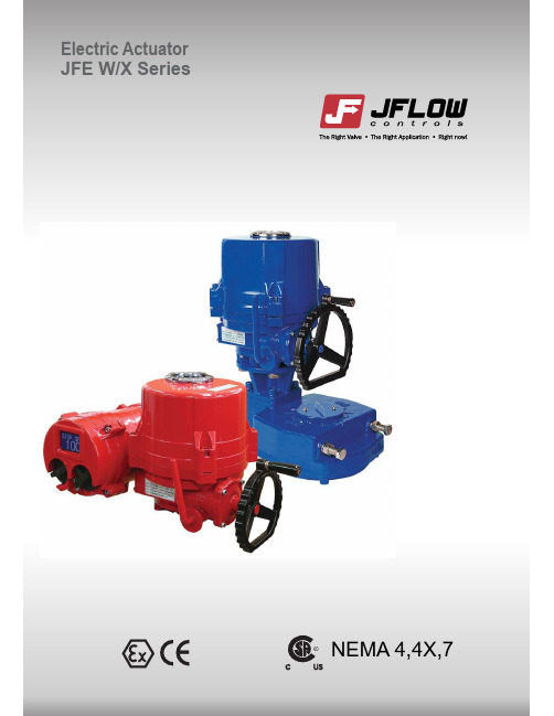
INTRODUCTION- Our years ofJFE series electric actuator which hasintegrate fully into systems.service.FEATURES- Compact and robust construction, light weight providing high output torque(Max 80,000 In-lbs / 9000Nm).- Wide range of torque variation (From min 885In-Lbs to max 80,000 In-Lbs).- Hard anodized aluminum housing inside and outside with external powder coated against severe industrial environment.- Enclosure using radial seals & O-rings that provide protection to waterproof IP67 (Nema 4 & 6) and optional watertight IP68- Mounting base according to ISO5211 standard.- Removable drive bushing for easy machining and mounting.- Self-locking provided by double worm gearing (no brake required).- Auto-declutching manual override handwheel with padlockable auto / manualswitchable lever.- Reliable Mechanical Torque sensing system providing safe operation in overload condition.- Large size window and indicator provides better position indication from a distance.- Various Local position control options providing easy commissioning and operation in field.- Digitalized control component.Cable entries- Standard 2-3/4NPTExternal mechanical stopper - Prevents over run of travel angle when limit switch fails.Removable drivebushing and ISO5211 mounting base- (F07~F30) for easy mounting on valve.GearingSelf locking- Provided by double worm gearing to keep position of valve unchanged against reverse torque from valve.CONSTRUCTIONCaptive cover bolts- Designed to prevent losing it during maintenance or installation.* All external bolts are stainless steel for rust prevention.- HousingSealing- By O-ring in all interfacesIP67(standard), and double o-ring for IP68 (option)Handwheel- Different sizes depending on actuator torque, and knob on handwheel for easy operation.Motor- Specially designed induction motor to generate high starting torque and high efficiency equipped with thermal protector to prevent damage from over heating.- Insulation class F- Hard anodized Aluminum casting and external epoxy powder coated against severe industrial environment.- Precisely machined double worm gear c/w minimumback-lash, low noise, high output torque.Tapered interface between cover and lower housing- For easy lifting cover up from lower housing for wiring or maintenance.StandardIndicator- Continuous mechanical position indicator and window with dialLimit switches- Directly engaged with driving shaft to setaccurate position of valve.- 2 ea for each travel end (open/close).- Optional Extra Limit Switches (Max 4 ea for each end) : Except for JFE 0100Torque switches- Protect actuator from damage caused byoverload from the driven valve over the whole travel.- 1 each for open / closeSpace Heater- Anti-condensationTerminal- Spring loaded push type terminal for tight wiring connection under severe vibration.Manual override- Auto / Manual switchable lever and handwheel engagement for emergency manual operation.- Drive force automatically resorted by motor start, unless lever padlocked toprevent this occuring.TECHNICAL INFORMATIONSTANDARD SPECIFICATIONModel JFE 0100JFE 0160JFE 0240JFE 0350JFE 0500JFE 0800JFE 1100JFE 2000JFE 3000JFE 6000JFE 9000EnclosureMain Power supply Control power supplyDuty cycle(on-off) Duty cycle(modulating)MotorLimit switchesTorque switches Stall protection/ set temp.Travel anglePosition indicatorManual overrideSelf locking Mechanical stopperSpace HeaterCable entriesLubricationTerminal block Ambient temperatureAmbient humidityAnti vibrationExternal coating Weatherproof IP67, NEMA4 4X and 6, O-ring sealed, Optional: CSA NEMA 7 110/220VAC/1Ph/50/60Hz, 380/440/VAC/3Ph/50/60/Hz110/220VAC/1Ph/50/60Hz 10%S2: 10Min~30MinS4, 30~50%, 300~1200 start/HourSquirrel Cage induction motor2 each for Open and Close (SPDT 250VAC/10A rating)1 each for Open and Close (SPDT 250VAC/10A rating except for JFE 0100) Built in Thermal protection, Open 150o C+-5o C, Close 97o C+-15o C90o 5o(0o~ 100o)Continuous mechanical indicator with arrowDe-clutchableProvided by double worm gearing (no brake)1 each for each travel end (Open and Close), external & adjustable5W(110/220VAC) for anti-condensationTwo - 3/4” NPTEP type greaseScrew and Lever Push type (spring loaded)Basic actuator : -20o C~+70o Cc/w control options : -10o C~+60o C90%RH Max (Non-Condensing)XYZ 10g. 02~34Hz, 30 minutesDry powder (Polyester)MechanicalOPTIONS AVAILABLERemote monitoring and controlLocal controlSymbol JFEX WT ALS A TS EXT SVRemarkApproved by CSA, ATEX, NEPSI 10M Head 100hours Except for JFE 0100Except for JFE with Gear box Please consult before orderingDescriptionExplosion proof (Class 1, Div 1, Grps C & D, Ex d II B T4) Watertight (IP68), Temporary submersible Auxiliary limit switches (Max 2 for each travel end)Auxiliary torque switches (Max 2 for each travel end)Extended travel angle (up to 120o, 135o, 180o, 270o,)Variation in torque and operating speedPKCTBusCommunication Potentiometer kit (output signal : 0~1 Kohm)High resolution potentiometer and precisely machined gearing are directly engaged with drive shaft to feedback continuous position of valveCurrent transmitter (output signal : 4-20mA)Zero / Span AdjustmentDHC Series Modulating controller (by input and output signal)Profibus Communication CANopen CommunicationInput : 4-20mA, 0-10VDC, 2~10VDC, 1~5VDC, 0~5VDC Optional Output : 4-20mA / 0-10VDC Lp4 for 1 & 3 Phase (JFEW 0100~9000)Lm4 for 3 Phase (JFEW 0100~9000)Including the same functions as LP4Control power : Free Voltage (85~265VAC) 50/60Hz, Option : 24VDC Magnetic selector switches, SMPS (Switching Module Power Supply) : Open/Close & Local/Stop/RemoteLocal lamp indicationReversing electric contactors, Transformer: Power - White(on), Remote : Blue(on), : In case of Close Torque Switch Trip - Yellow(on) + Green (flickering : only at Local Position): In case of Open Torque Switch Trip - Yellow(on) + Red (flickering : only at Local Position): Full Close - Green(on), Closing - Green(flickering : only at Local Position): Full Open - Red(on), Opening - Red(flickering : only at Local Position)* Options Available : PK, CT, RPC(Modulating), IP68, Explosion proofPKCTLP4 / LM4DHC SeriesDHC Series Modulating Controller450 Points of ResolutionICM2 for 1 & 3 phase (integral with LCD Display) (JFEW 0160~9000)ICM3 for 1 & 3 phase (integral with LCD Display/IP68 Enclosure) (JFEW 0160~9000)Reversing electric contactors, Transformer,Auto-Phase Discriminator, LCD Display Including the same functions as ICM1Including the same functions as ICM2Reversing electric contactors, Transformer, Auto-Phase Discriminator,LCD Display, IP68, Explosion Proof, RPC(Modulating), Bus Communication, 34pins seperate compartment for terminal blockLocal controlFail safeBP for 1 Phase (JFEW 0160~0500)Rechargeable Battery back up - Fail safe function / Optional: Super Capacitors When Main power is alive, actuator works as normally.Once power fails, actuator will move to pre-set fail safe position. Input power : Free Voltage (85~265 VAC) 50/60Hz Output contacts : open/close/Alarm relayLED signal indication : 4 LEDs (Full Open/Close, Over Torque and Power)Rechargeable battery : 2.0AH 27.5VDC(Ni-Cd)ICM1 for 1 & 3 Phase (Integral Control Module) (ITQ 0160~9000)Control power : 24 VDC (Internal Power) (Option : 110 VAC, 220 VAC (External Power)) Main Power : 3Ph / 220/380/440 VAC1Ph / 110/220 VACMagnetic selector switches: Open/Close & Local/Stop/RemoteReversing electric contactors, Transformer, Phase Detector Auto-Phase DiscriminatorLocal lamp indication: Power - White(on), Remote : Blue(on),: In case of Close Torque Switch Trip - Yellow(on) + Green(flickering): In case of Open Torque Switch Trip - Yellow(on) + Red(flickering): Full Close - Green(on), Closing - Green (flickering): Full Open - Red(on), Opening - Red (flickering):Single & Reverse Phasing : (Yellow + Green + Red) all flickering * Options Available : Explosion Proof, IP68* Options Available : CT, RPC(Modulating), Explosion Proof,IP68, Bus CommunicationICM1ICM2BASIC ACTUATOR DIMENSIONSWith Gear BoxJFE 6000JFE 9000TYPICAL WIRING (JFE W/X 0100)110/220VAC/50/60Hz, 1Ph(On-Off)110/220VAC/50/60Hz, 1Ph(Modulating : RPC)380/440VAC/50/60Hz, 3Ph(On-Off)**Important Notice**1. The Electric Wiring Diagrams shall be modified withterminal no and wires in Red Color for our customers’ convenience from 1st of June 2009.2. Please only refer to the Wiring Diagram Sticker or separate Wiring Diagram inside of each actuator. If there is any confusion please contact our distributor.380/440VAC/50/60Hz, 3Ph(On-Off)110/220VAC/50/60Hz, 1Ph(Modulating : RPC)110/220VAC/50/60Hz, 1Ph(On-Off)ALS : Auxiliary Limit SwitchAOLS : Auxiliary Open Limit Switch (Dry contact)ACLS : Auxiliary Close Limit Switch (Dry contact)O : Open Lamp C : Close Lamp OT : Over Torque LampCLS : Close Limit Switch (250VAC 10A)OLS : Open Limit Switch (250VAC 10A)CTS : Close Torque Switch (250VAC 10A)OTS : Open Torque Switch (250VAC 10A)CC : Close Magnetic Coil OC : Open Magnetic Coil M : MotorTP : Thermal Protector (250VAC 15A option)MTP : Thermal Protector built in motor* Each actuator should be powered through its own individual switch or relay contacts to prevent crossfeed between two or more actuators.* In case of 3ph actuator, make sure to place actuator on the middle of travel angle before electrical operation to avoid "Jamming"* All internal wiring is done as color coding.TYPICAL WIRING (ITQ 0160 ~ ITQ 9000)L WIRING (ICM2 for 3phaseThe details of this catalog are subject to change without prior notification.AdditionalJflow Controls ProductsElectric ActuatorMULTI-TURN 0180 / 0450 / 0750 / 1800 / 3000。
JFE系列电动执行器安装和操作手册说明书

Limit switches
OPEN/CLOSE, SPDT, 250V AC 10A RATING
Torque switches Stall protection(Temp.)
OPEN/CLOSE, SPDT, 250V AC 10A Rating(Except for 0100) Built in thermal protection, OPEN 150℃±5℃/CLOSE 97℃±15℃
®
3
JFE SERIES ELECTRIC ACTUARTER
Many thanks for purchasing our JFEW/X series electric actuator!
For safe and proper operation, please carefully read this manual before using it and save it for reference. Important Note : The contents of this manual are subject to change without individual notice .
1) Before wiring 3) Checking the rotating direction
of actuator
2) Electrical wiring 4) Commissioning(Electrical)
7. Others
1) Jamming 2) Special tools for setting
3. Sizing and Application
4. Setting
2) Internal component 4) Features & Structure 6) Removable drive bushing
DFMO995FVRl 单压力计说明书
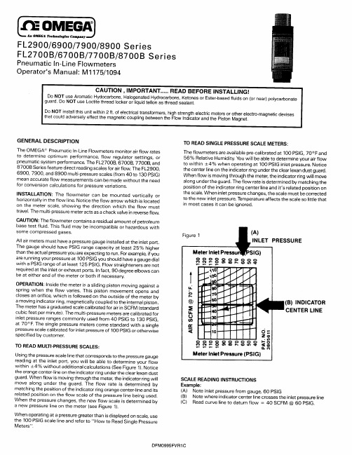
Do NOT install this unit within 2 ft. of electrical transformers, high strength electric motors or other electro-magnetic devises that could adversely effect the magnetic coupling between the Flow Indicator and the Piston Magnet.
The OMEGA ’“’Pneumatic In-Line Flowmeters monitor air flow rates to determine optimum performance, flow regulator settings, or pneumatic system performance. The FL27OOB, 67OOB, 77008, and 8700B Series feature direct reading scales for air flow. The FL2900, 6900, 7900, and 8900 multi-pressure scales (from 40 to 130 PSIG) mean accurate flow measurements can be made without the need for conversion calculations for pressure variations.
L An OMEGA Tedinologl.a Cmm,.myl/
阿玛紧防火套应用手册说明书

2/// F irestop, thermal insulation and condensation control in one step // F ire resistance for A-60(bulkhead and deck) and B-15 (bulkhead) application (certified by DNV and Bureau Veritas)// L arge approval range for pipes with diameter up to 89 mm and fire resistance up to A-60// F or application with cold service pipes (from -50°C up to +85°C)//E nergy-efficient insulation: λ ≤ 0.056 W/(m·K) at 0°C // C losed-cell structure for long-term condensation control (with μ ≥ 7000)// N o mineral wool fibres - dust and fibre-free application // C an be combined with IMO certified ArmaFlex products as continued insulationSOLUTION WITH THERMAL INSULATION PROPERTIES// A vailable as tubes (insulation thickness from 16 to 25 mm) and sheets (13 mm insulation thickness)// W ith intumescent components // S pecifiable solution - firestop penetrations can be planned from early beginning // E nsuring compliance – firestop material is already installed in the early stage // N o risk of delays within theproject – no need to apply further firestop material // E asy, clean and compliant installation // Cost-efficient firestop solution // Easy inspection// L ow effort for maintenance within the lifetime of a shipor offshore platformConventional design for A-60 (metal sleeve)Non-conventional design for A-60 (without metal sleeve)KEY BENEFITSThis productguarantees reliable fire safety in all A-class divisions (A-60 class decks and bulkheads) without the need for any complicated additionalmeasures.ARMAFLEX PROTECT - INSTALLATION INSTRUCTIONS/3//T ested in steel, copper and multi-layer composite pipes in steelbulkhead and decks//A pproved as pipe penetrations byDNV (Module B) and BureauVeritas (Module D) - “A” classdivisions (bulkhead and deckpenetrations) and B-15 bulkheadpipe penetration//P ipe penetration system forsingle fitted with a layer ofcontinuous IMO approved pipeinsulation type “ArmaFlex”.“ArmaFlex” insulation must havea minimum thickness of 13 mmand a density of 45 – 65 kg/m³ likeAF/ArmaFlex, AF/ArmaFlex Evo,ArmaFlex Ultima etc.//I n the area of the divisionpenetration the continuous pipeinsulation is replaced by localinsulation of type “ArmaFlexProtect” with a length of at least1000 mm (for A-60 applications)and 200 mm (for B-15applications), equally distributedon each side of the bulkhead.//B ranches, elbows, couplingsor pipe supports shall also beinsulated with “ArmaFlexProtect” along with requiredminimum insulation length asfor straight pipes.APPLICATIONARMAFLEX PROTECT - INSTALLATION INSTRUCTIONS4/APPROVED FOR USE AS A PIPE PENETRATION SYSTEM THROUGH “A” CLASS DIVISIONS: PIPE, DUCT, TRUNK, ETC. PENETRATIONPipe penetration system for single fitted with a layer of continuous IMO approved pipe insulation type “ArmaFlex”. Minimum thickness of “ArmaFlex” insulation see below tables, the density must be45 – 65 kg/m³ like AF/ArmaFlex.In the area of the division penetrationthe continuous pipe insulation isreplaced by local insulation of type“ArmaFlex Protect” with a length of1000 mm, preferable 500 mm oneach side of the bulkhead or deck.Branches, elbows, couplings or pipesupports like “ArmaFix®” shall alsobe insulated with “ArmaFlex Protect”along with required minimuminsulation length as for straightpipes without any restrictions of thedistance to the division.TYPE OF PIPE PENETRATIONS//Conventional design with steel sleeve//Non-conventional design without steel sleeve CONVENTIONAL DESIGNCircular steel sleeve, minimum length 100 mm, welded to the deck or bulkhead opening. The steel sleeve insulation positioned on the upper (non-insulated) side of the deck. The insulation material shall be of approved type with a density with at least 66 kgm³ and thickness of 30 mm or equivalent. For A-60 steel bulkhead and decks,general application, i.e. no limitationon the positioning of penetrationsleeves in decks or bulkheads.For application on A-0, A-15 and A-30divisions, the penetration systemshall be insulated as approved forclass A-60. The penetrated divisionis to be insulated with A-60 at least200 mm around the penetration.Other applications are subject tocase-by-case-approval.For application on offshorestructures the requirementsspecified in the applicable DNVOffshore Rules may have to beobserved.The penetration system is onlyapproved for pipes and pipeinsulation as shown in the table onnext page for use in cold service1pipework on refrigeration systemseverywhere onboard, and otherpiping systems, limited to cargoareas, mail rooms, baggagerooms and refrigeratedcompartments of service spaces,and exterior locations (SOLASII-2/5.3.1.1). APPLICATION / LIMITATIONAPPROVED PIPING SYSTEMSAND INSTALLATION AREAS1 P iping for hot or cold sanitary water is notconsidered as “cold service system”.FOR A-60ARMAFLEX PROTECT - INSTALLATION INSTRUCTIONS/5A-60 CLASS STEEL DECK PENETRATION WITH “SYSTEM ARMAFLEX PROTECT” THROUGH STEEL SLEEVESPipe materialPipe outer diameter (mm)ArmaFlex Protect ArmaFlex Sika Firesil Marine N Steel sleeve Average insulation thickness (mm)Length (mm)Minimum insulation thickness (mm)Average thickness (mm)Wall thickness (mm)Steel ≥ 15 – ≤ 8919 – 25≥ 100013 ± 1.5 mm ≤ 11 2.9 – 4.0Copper≥ 15 – ≤ 5419 – 25≥ 100013 ± 1.5 mm ≤ 11 2.9 – 3.6Aluminum reinforced polyethylene (PE-Xc/Al/PE-Xc)≥ 16 – ≤ 2020≥ 100013 ± 1.5 mm≤ 103.6AND PIPE MATERIALA) CONVENTIONAL DESIGNARMAFLEX PROTECT - INSTALLATION INSTRUCTIONS6/A-60 CLASS STEEL BULKHEAD PENETRATION WITH “SYSTEM ARMAFLEX PROTECT” THROUGH STEEL SLEEVESPipe materialPipe outer diameter (mm)ArmaFlex Protect ArmaFlex Sika Firesil Marine N Steel sleeve Average insulation thickness (mm)Length (mm)Minimum insulation thickness (mm)Average thickness (mm)Wall thickness (mm)Steel≥ 15 – ≤ 8919 – 25≥ 100013 ± 1.5 mm≤ 9.52.9 – 4.0Aluminum reinforcedpolyethylene pipes (PE-Xc/Al/PE-Xc)≥ 16 – ≤ 329.7≥ 100013 ± 1.5 mm ≤ 9.73.6ARMAFLEX PROTECT - INSTALLATION INSTRUCTIONS/7A-60 CLASS STEEL BULKHEAD PENETRATION WITH “SYSTEM ARMAFLEX PROTECT” THROUGH STEEL SLEEVESPipe material Pipe outerdiameter(mm)ArmaFlex Protect 1)ArmaFlex Sika FiresilMarine NSteelsleeve Averageinsulationthickness(mm)Length(mm)MinimumInsulationthickness(mm)Averagethickness(mm)Wallthickness(mm)Copper pipes ≥ 12 – ≤ 5419 – 25≥ 100013 ± 1.5 mm≤ 10.9 2.9 – 4.01) A second layer of 13 mm ArmaFlex Protect sheet starting from the sleeve has to be applied.ARMAFLEX PROTECT - INSTALLATION INSTRUCTIONS8/A-60 CLASS STEEL DECK AND BULKHEAD PENETRATION WITH “SYSTEM ARMAFLEX PROTECT”Pipe material Pipe outerdiameter(mm)ArmaFlex Protect ArmaFlex Sika Firesil Marine N Averageinsulationthickness(mm)Length(mm)Minimuminsulationthickness(mm)Averagethickness(mm)Steel ≥ 15 – ≤ 8919 – 25≥ 100013 ± 1.5 mm8 Copper ≥ 15 – ≤ 5419 – 25≥ 100013 ± 1.5 mm8 Aluminumreinforced polyethylene (PE-Xc/Al/PE-Xc)≥ 16 – ≤ 2020≥ 100013 ± 1.5 mm8B) NON-CONVENTIONAL DESIGNARMAFLEX PROTECT - INSTALLATION INSTRUCTIONS/9A tube of “ArmaFlex Protect” can be either pushed onto the pipe orslotted and glued at the longitudinal joint. Using a sharp knife, slit the tube along its entire length. Place the slit tube onto the clean pipe, apply ArmaFlex adhesive based on polychloroprene (e.g. ArmaFlex 520, ArmaFlex HT625, ArmaFlex RS850,ArmaFlex 525) to the two cut edges applying a thin even film of adhesive using a short bristle brush. Apply the adhesive at 200 mm intervals, along the tube. Allow the adhesive to become touch dry (test with thefingernail). Free the seams from the pipe where applicable, then line up the edges together and press theAPPLICATIONseam together with firm evenpressure to finish. Push ArmaFlex Protect tube into the centre of the bulkhead resp. deck penetration. The ArmaFlex installation manual is part of these installation instructions and can be found in the download area at .NON-CONVENTIONAL DESIGNThe residual gap between the ArmaFlex Protect surface and the steel sleeve has to be sealed completely with SIKA Firesil Marine N. For this the surfaces must be clean, dry and free from all traces of oil, grease and dust. Cut the nipple from the thread of the cartridge. Trim the nozzle to therequired size. Use a cartridge hand-, air- or battery-driven gun. Tooling and finishing of the sealant surfaceCONVENTIONAL DESIGNFor copper pipes in a bulkheads (conventional design), apply a second layer of 13 mm ArmaFlex Protect sheet starting from the sleeve. The length of ArmaFlex Protect is min. 200 mm. Determine the circumference of the first layer of ArmaFlex Protect. Use a strip of ArmaFlex Protect sheetmaterial to do this. Do not stretch the strip. Transfer circumference length determined to the sheet and cut out the piece. Apply a thin coat of ArmaFlex adhesive to the cut edges and allow tacking dry. Press together at the two ends first, then in the middle. From here, close the seam completelyworking from the inside to the outside. ARMAFLEX PROTECT - INSTALLATION INSTRUCTIONS must be carried out within the tack-free time (appr. 120 minutes at 23°C / 50%) of the sealant. Werecommend the use of Sika tooling Agent N. Other finishing agents or lubricants must be tested for suitability and compatibility. The application temperature of the sealant is 5 °C – 40 °C.Further information on SIKA Firesil Marine N is available at: or www.sika.ch.The remaining gap (8 mm) between deck resp. bulkhead and theArmaFlex Protect surface has to be sealed with SIKA Firesil Marine N.For this the surfaces must be clean, dry and free from all traces of oil, grease and dust.10/1. ArmaFix pipe support2. ArmaFlex Protect tube or sheet3. ArmaFlex Protect double layer4. ArmaFlex Protect overlap (thickness min. 13 mm)5. Connection thread6. Threaded barThe ArmaFlex installation manual is part of theinstallation instructions and can be found in thedownload area at .1. I nstall ArmaFlex Protect on eitherside of the ArmaFix pipe support.Wet seal the butt joints of theArmaFix pipe support usingArmaFlex adhesive.Note: Ensure that the pipe insulation isinstalled under slight compression.2. C lean the surface of the ArmaFix pipe support using ArmaFlex cleaner.3. A pply ArmaFlex adhesive on the surfaces which are to be glued. Allow this first layer of ArmaFlexadhesive to dry. 4. A pply a second thin coat of adhesive evenly on both the surface of the clamp and the ArmaFlex adhesive joints. After the adhesive has cured, the joints should be pressed together briefly, but firmly.5. I f necessary, double the ArmaFlex thickness to the diameter of the pipe support.6. T o secure the butt joints, apply an overlapping strip of ArmaFlex using all-over adhesive coverage.“ArmaFix“ pipe supports represent the best solution to create a fullywater-vapour-tight system and prevent condensation on coldapplications. If the ArmaFix pipe support is located inside theArmaFlex Protect partition, the following must be observed: ARMAFIX PIPE SUPPORTSchematic cross-section of a connection of ArmaFlex Protecttubes or sheets with ArmaFix pipe support.ARMAFLEX PROTECT - INSTALLATION INSTRUCTIONS/11APPROVED FOR USE AS A PIPE PENETRATION SYSTEM IN CLASS B-15 BULKHEADSApproved for use in class B-0 and B-15 when the penetration system is insulated to B-15 bulkhead from SAINT GOBAIN ISOVER G+H AG, “ULTIMATE U SeaProtect Slab 66 A-A“.The penetration system is only approved for the pipes and pipe insulation as in the table below for use as cold service pipework on refrigeration systems everywhereonboard, and for pipework in cargo areas, mail rooms, baggage rooms and refrigerated compartments of service spaces, and exteriorlocations (SOLAS II-2/5.3.1.1).Approved B-15 bulkhead fromB-15 BULKHEAD PENETRATION WITH “SYSTEM ARMAFLEX PROTECT”Pipe materialPipe outer diameter (mm)ArmaFlex Protect Average insulation thickness (mm)Length (mm)Steel ≥ 15 – ≤ 8919 – 25≥ 200Copper≥ 15 – ≤ 5419 – 25≥ 200Multi-layer plastic pipes≥ 15 – ≤ 6319 – 25≥ 200FOR B-15ARMAFLEX PROTECT - INSTALLATION INSTRUCTIONS12/A tube of “ArmaFlex Protect” can be either pushed onto the pipe or slotted and glued at the longitudinal joint. Using a sharp knife, slit the tube along its entire length. Place the slit tube onto the clean pipe, apply ArmaFlex adhesive based on polychloroprene (e.g. ArmaFlex 520, ArmaFlex HT625, ArmaFlex RS850) to the two cut edges applying a thin even film of adhesive using a short bristle brush. If the ArmaFlex Protect tube is longer than 200 mm, apply the adhesive at 200 mm intervals along the tube.Allow the adhesive to become touch dry (test with the fingernail). Free the seams from the pipe where applicable, then line up the edges together and press the seam together with firm even pressure to finish.Push the ArmaFlex Protect tube into the penetration until the tube length is at least 75 mm on each side of the B-15 bulkhead (total length at least 200 mm).APPLICATIONCover the area between the pipepenetration and the B-15 wall withself-adhesive aluminium tape. To dothis, apply the aluminium tape to theB-15 bulkhead over the ArmaFlextube so that any openings in thepenetration are sealed.The continuous ArmaFlex insulationmust be installed according to theArmaFlex manual and can be foundin the download area at.ARMAFLEX PROTECT - INSTALLATION INSTRUCTIONS/13TECHNICAL DATA - ARMAFLEX PROTECT Brief description Flexible fire seal and insulation for metal and composite pipes through fire-resistant walls and floors (up to EI 120).Material type Elastomeric foam based on synthetic rubber.Product colour range BlackInstallationFor industrial applications it is recommended to consult the relevant Armacell application manual(s). Use ArmaFlex 520 adhesive for a reliable and seamless installation.A p p r o v a l s a n d c o m p l i a n c e Specification complianceP r o p e r t yV a l u e / A s s e s s m e n tS t a n d a r d / T e s t m e t h o dT e m p e r a t u r e r a n g e Service temperatureMin. °C Max. °C -5085EN 14706, EN 14707, EN 14304T h e r m a l c o n d u c t i v i t yDeclared thermal conductivityΘm0 °C λd ≤ [W/(m·K)]0.056Formulaλd = 0.056 + 0,0001 · ϑmEN 12667, EN ISO 8497F i r e P e r f o r m a n c e a n d A p p r o v a l sFire resistance of bulkhead and decks B-15 bulkheads up to 89 mm A-60 bulkheads and decks up to 89 mm IMO 2010 FTP code, Part 3 (IMO A.754(18))P a s s i v e f i r e p r o t e c t i o n Fire resistance of elements of construction up to EI 120EN 13501-2, EN 1366-3F i r e p e r f o r m a n c e Practical fire behaviour Self-extinguishing, does not drip, does not spread flames R e s i s t a n c e t o w a t e r v a p o u r Water vapour diffusion resistance factor μ ≥ 7,000EN 12086, EN 13469H e a l t h a n d e n v i r o n m e n t Volatile organic compounds (VOC) content Fulfills all VOC requirements (French, Italian, Belgian, German AgBB, Blauer Engel and Eurofins Indoor Air Comfort GOLD).ISO 16000 Parts 3, 6 & 9Health aspects Please refer to latest product Safety Datasheet (SDS).Emission of dangerous substances No dangerous substances.Additional features SCCP, MCCP-freeO t h e r t e c h n i c a l f e a t u r e s Shelf lifeNo shelf life.Meets IMO FTP Code 2010, part 3•P r o p e r t yV a l u e / A s s e s s m e n tS t a n d a r d / T e s t m e t h o dStorageCartons shall be stored horizontally.Can be stored in dry, clean rooms at normal relative humidity (50 % - 70 %) and ambient temperature (0 °C - 35 °C).Minimum temperature for transport -50 °C under condition of frost-free storage before installation.14/TECHNICAL DATA - ARMAFLEX PROTECTT u b e–s t a n d a r d.B l a c kP i p eØ[m m]I t e m D e s c r i p t i o n I n s u l a t i o n t h i c k n e s s[m m]P r i m a r y c o n t e n t[m e t r i c]1634 m6PRO-AX-16X006ArmaFlex Protect tube (1 m,outer-Ø 6 mm, 16 mm insulationthickness)1630 m8PRO-AX-16X008ArmaFlex Protect tube (1 m,outer-Ø 8 mm, 16 mm insulationthickness)1918 m10PRO-AX-19X010ArmaFlex Protect tube (1 m,outer-Ø 10 mm, 19 mm insulationthickness)1917 m12PRO-AX-19X012ArmaFlex Protect tube (1 m,outer-Ø 12 mm, 19 mm insulationthickness)1916 m15PRO-AX-19X015ArmaFlex Protect tube (1 m,outer-Ø 15 mm, 19 mm insulationthickness)2014 m16PRO-AX-20X016ArmaFlex Protect tube (1 m,outer-Ø 16 mm, 20 mm insulationthickness)2013 m18PRO-AX-20X018ArmaFlex Protect tube (1 m,outer-Ø 18 mm, 20 mm insulationthickness)2012 m20PRO-AX-20X020ArmaFlex Protect tube (1 m,outer-Ø 20 mm, 20 mm insulationthickness)22PRO-AX-20X022ArmaFlex Protect tube (1 m,2012 mouter-Ø 22 mm, 20 mm insulationthickness)2011 m25PRO-AX-20X025ArmaFlex Protect tube (1 m,outer-Ø 25 mm, 20 mm insulationthickness)259 m28PRO-AX-25X028ArmaFlex Protect tube (1 m,outer-Ø 28 mm, 25 mm insulationthickness)258 m32PRO-AX-25X032ArmaFlex Protect tube (1 m,outer-Ø 32 mm, 25 mm insulationthickness)35PRO-AX-25X035ArmaFlex Protect tube (1 m,258 mouter-Ø 35 mm, 25 mm insulationthickness)40PRO-AX-25X040ArmaFlex Protect tube (1 m,25 6 mouter-Ø 40 mm, 25 mm insulationthickness)25 6 m42PRO-AX-25X042ArmaFlex Protect tube (1 m,outer-Ø 42 mm, 25 mm insulationthickness)25 5 m48PRO-AX-25X048ArmaFlex Protect tube (1 m,outer-Ø 48 mm, 25 mm insulationthickness)25 5 m50PRO-AX-25X050ArmaFlex Protect tube (1 m,outer-Ø 50 mm, 25 mm insulationthickness)25 5 m54PRO-AX-25X054ArmaFlex Protect tube (1 m,outer-Ø 54 mm, 25 mm insulationthickness)25 4 m60PRO-AX-25X060ArmaFlex Protect tube (1 m,outer-Ø 60 mm, 25 mm insulationthickness)25 4 m63PRO-AX-25X063ArmaFlex Protect tube (1 m,outer-Ø 63 mm, 25 mm insulationthickness)/15TECHNICAL DATA - ARMAFLEX PROTECTT u b e–s t a n d a r d.B l a c kP i p eØ[m m]I t e m D e s c r i p t i o n I n s u l a t i o n t h i c k n e s s[m m]P r i m a r y c o n t e n t[m e t r i c]76PRO-AX-25X076ArmaFlex Protect tube (1 m,outer-Ø 76 mm, 25 mminsulation thickness)25 4 m89PRO-AX-25X089ArmaFlex Protect tube (1 m,outer-Ø 89 mm, 25 mm insulationthickness)25 4 mR o l l-s t a n d a r d.B l a c kI t e m I n s u l a t i o n t h i c k n e s s[m m]D e s c r i p t i o n W i d t h(m)L e n g t h[m]P r i m a r y c o n t e n t[m e t r i c]PRO-AX-13MM/E13ArmaFlex Protect sheet (6m x 0,5 m, 13 mminsulation thickness)0.56 6 m²ArmaFlex Protect -ideal for condensation control on refrigeration and coolant pipingdiameterLine temperature / Ambient temperature+6 °C / 23 °C0 °C / 23 °C-5°C / 23 °C-10°C / 23 °C≥ 10 mm ≤ 323,9 mm Relative humidity≤ 80 %Relative humidity≤ 75 %Relative humidity≤ 70 %Relative humidity≤ 65 %16/ARMAFLEX PROTECTFor product information, please visit: ABOUT ARMACELLAs the inventor of flexible foam for equipment insulation and a leading provider of engineered foams, Armacell develops innovative and safe thermal and mechanical solutions that create sustainable value for its customers. Armacell’s products significantly contribute to global energy efficiency making a difference around the world every day. With more than 3,300 employees and 27 production plants in 19 countries, the company operates two main businesses, Advanced Insulation and Engineered Foams. Armacell focuses on insulation materials for technical equipment, high-performance foams for acoustic and lightweight applications, recycled PET products, next-generation aerogel technology and passive fire protection systems.。
敏赛特技术有限公司 FCHM 系列水力控制模块规格说明书

| FCHM SERIES HYDROMATIC PUMP CONTROL MODULESPECIFICATIONS A compact unit, which combines all the functions of a complete pressurising system, ie. Pressure Switch, Dry Running cut-out, Control Panel, Pressure Reservoir and Non-return Valve. The system employs a hydraulic chamber, equipped with a damping system to protect against water hammer, and a patented electromechanical control board, to be connected to 240Vac power source, with an internal 24V secondary circuit.Compared with conventional systems this is not only more compact, but easier and quicker to install, and makes for significant energy savings and reduced pump wear. It is also maintenance free, as the pressurisation unit does not require precharging with air.This system combines the versatility and control of conventional pressure switches with the advantages of pressure/flow switches.Avoids the need for pressure reservoirs, along with their associated maintenance costs.Features• Start up pressure 1-3.5 bar, adjustable• Dry running cut out and foot valve• Visual Indication and manual reset for water circuit faults• Pressure gauge for easy set up• Auxiliary fuse to protect pump control circuitSupply voltage240Vac 50-60HzPage 1Page 2DIMENSIONSPress Switch Min. PressPressure VesselDry RunningControl PanelFoot ValveWITH FCHMfromSubmersible pumpAlways install a pump that develops a maximum output pressure that is at least 1 bar greater than the required minimum start up pressure.If the head to be pumped is greater than 15m, it is necessary to in-crease the start up pressure setting e.g. 20m head requires at least 2.5 bar start up pressure, 25m head requires at least 3 bar start up pressure.To increase the start up pressure setting:reer se g. ar ad up at ut ar dPage 3CONTACT USCynergy3 Components Ltd.7 Cobham Road,Ferndown Industrial Estate, Wimborne, Dorset,BH21 7PE, United KingdomSensata Technologies, Inc. (“Sensata”) data sheets are solely intended to assist designers (“Buyers”) who are developing systems that incorporate Sensata products (also referred to herein as “components”). Buyer understands and agrees that Buyer remains responsible for using its independent analysis, evaluation and judgment in designing Buyer’s systems and products. Sensata data sheets have been created using standard laboratory conditions and engineering practices. Sensata has not conducted any testing other than that specifically described in the published documentation for a particular data sheet. Sensata may make corrections, enhancements, improvements and other changes to its data sheets or components without notice.Buyers are authorized to use Sensata data sheets with the Sensata component(s) identified in each particular data sheet. HOWEVER, NO OTHER LICENSE, EXPRESS OR IMPLIED, BY ESTOPPEL OR OTHERWISE TO ANY OTHER SENSATA INTELLECTUAL PROPERTY RIGHT, AND NO LICENSE TO ANY THIRD PARTY TECHNOLOGY OR INTELLECTUAL PROPERTY RIGHT, IS GRANTED HEREIN. SENSATA DATA SHEETS ARE PROVIDED “AS IS”. SENSATA MAKES NO WARRANTIES OR REPRESENTATIONS WITH REGARD TO THE DATA SHEETS OR USE OF THE DATA SHEETS, EXPRESS, IMPLIED OR STATUTORY, INCLUDING ACCURACY OR COMPLETENESS. SENSATA DISCLAIMS ANY WARRANTY OF TITLE AND ANY IMPLIED WARRANTIES OF MERCHANTABILITY, FITNESS FOR A PARTICULAR PURPOSE, QUIET ENJOYMENT, QUIET POSSESSION, AND NON-INFRINGEMENT OF ANY THIRD PARTY INTELLECTUAL PROPERTY RIGHTS WITH REGARD TO SENSATA DATA SHEETS OR USE THEREOF.All products are sold subject to Sensata’s terms and conditions of sale supplied at SENSATA ASSUMES NO LIABILITY FOR APPLICATIONS ASSISTANCE OR THE DESIGN OF BUYERS’ PRODUCTS. BUYER ACKNOWLEDGES AND AGREES THAT IT IS SOLELY RESPONSIBLE FOR COMPLIANCE WITH ALL LEGAL, REGULATORY AND SAFETY-RELATED REQUIREMENTS CONCERNING ITS PRODUCTS, AND ANY USE OF SENSATA COMPONENTS IN ITS APPLICATIONS, NOTWITHSTANDING ANY APPLICATIONS-RELATED INFORMATION OR SUPPORT THAT MAY BE PROVIDED BY SENSATA.Mailing Address: Sensata Technologies, Inc., 529 Pleasant Street, Attleboro, MA 02703, USA.Made in the UKWiring for 1phase pumps up to 2HP Wiring for 1phase pumps over 2HPWiring for 3phase pumpsphase pumps。
J Flow Controls JFD系列弹簧和膜驱动器说明书

APPLICA TIONS&INDUSTRIES FEATURES&BENEFITS• Female Star Drive• Adjustable travel stops for both fully open and fully closed positions• High cycle life design• Low maintenance• Rolling diaphragm for linear torque output for accurate control• One piece diaphragm retainer and Nylon bearings for low friction, smooth operation and long cycle life • Field reversible for fail open/closed on rotary control valves and high performance butterfly valves • Mechanical lockout option• Adjustable travel stops for both open and closed positions • Air• Gas• Water• Oil• Other supply media compatible with the ductile iron/carbon steel casing of theactuator®DimensionsCH1.58 1.58W14-M5x0.8PQ Q1WCHD 1.18D 10.160.831.181.161.18D1.58A A1BC1/2" NPTSize A A1B C D D1Q Q1W W1CHISO 5211Wt (lbs)JFD115SR16.7613.628.946.36 5.44 3.96 1.97 2.761/4-20 UNC5/16-18 UNC 0.55F05/0729JFD300SR 19.3815.8710.757.766.36 4.41 2.76 4.025/16-18 UNC3/8-16 UNC0.87F07/1073JFD530SR27.1922.1312.1415.019.16 6.52 4.02 4.933/8-16 UNC1/2-13 UNC1.06F10/12237SpecificationsSeries SizeDesign Spring Rating JFD115SR Spring Return4030060*53080* Standard 60 psig springPart #Total Volumein 2Swept Volumein 2Air Stroke (seconds)*Spring Stroke (seconds)*Effective DiaphragmArea - in 2JFD115SR65412219JFD300SR 1991385 1.539JFD530SR 7195353299* Times may vary due to applicationTorques (in-lb)Part #40 PSI60 PSI80 PSISpring EndAir End Spring EndAir End Spring EndAir End JFD115135259309309465319JFD300695795138599517951409JFD530317936954865550967657095Wide range of readily available STANDARD options such as:• Direct mount declutchable and end mount manual overrides• NAMUR and non-NAMUR limit switches, positioners, and/or position transmitters • Pipe nipple mounted solenoid valves • Stainless steel tubing and fittingsJ-Flow Actuators, Matched for High PerformanceJ-Flow manufactures J-Torq TM actuators in three different versions•J-Flow's JFD Spring & Diaphragm Actuator for compact, precise control in easy field changeable fail open and fail closed. Actuator to valve mounting complies with ISO 5211 standard and positioner mounting complies with NAMUR standard. Three different sizes are available for actuation up through 12" J-Flow DM9900F segmented V-ball control valves•J-Flow's JFC Double Rack and Pinion Actuator for compact, precise control in both double acting and spring return de-signs. Actuator to valve mounting complies with ISO 5211 standard and positioner mounting complies with NAMUR stan-dard. Several different sizes are available for actuation up through 12" J-Flow DM9900F segmented V-ball control valves•J-Flow's larger JFE Electric Actuator for compact, precise control in both fail last and fail (open or closed). Control boards are available for a variety of input and output control signals. Actuator to valve mounting complies with ISO 5211. Optional enclosures are available to meet many of the required electrical area classifications.Parts of Identification6225543415262223158247912231921272817162014131011182930313223While the information and specifications contained in this literature are believed to be accurate, they are supplied for informative purposes only and should not be considered certified or a guarantee of satisfactory results. Nothing contained herein is to be construed as a warranty or guarantee, express or implied, regarding any matter with respect to this product. Because J Flow Controls ® is continually improving and upgrading its product design, the specifications, dimensions and information contained herein are。
- 1、下载文档前请自行甄别文档内容的完整性,平台不提供额外的编辑、内容补充、找答案等附加服务。
- 2、"仅部分预览"的文档,不可在线预览部分如存在完整性等问题,可反馈申请退款(可完整预览的文档不适用该条件!)。
- 3、如文档侵犯您的权益,请联系客服反馈,我们会尽快为您处理(人工客服工作时间:9:00-18:30)。
实际使用有效氯浓度:5 mg/L 试验时的有效氯浓度: 20 and 50 mg/L
160
140
Untested
50 days
120
210 days
100
340 days
80
60
40
20
0
Untested
Artificial Seawater
Artificial
Artificial
Seawater + Seawater +
・不需要供给药剂
・有氢气产生,要防爆 ・杀菌效果易受海水成分影响 ・需要电极更换 ・耗电量大(1000m3/hr >> 50kw)
・有臭氧产生,对身体有危害 ・设备多,故障率高,成本大 ・耗电量大(1000m3/hr >> 87kw )
可通过2种溶液的混合在现场制 ・原液错误混合时有爆炸的危险性 造,原液浓度高,储存容器小 ・分解物(游离氯)对身体有危害
Ballast water Volume(m3)
5,000 10,000 15,000 25,000 50,000 100,000
Biocide (m3)
0.25 0.5 0.75 1.25 2.5 5.0
Reducing agent
Powder (kg) Solution (m3)
15
0.14
30
IMO公约实施日程(假设)
2012年1月
2014年1月
2017年1月
2019年1月
新造船DWT15000以下
Байду номын сангаас
新造船DWT15000以上
旧船DWT15000以下
旧船DWT15000以上
5
设认可备步认骤证步骤
按照国际国内法进行严格的审查
G8型式(装置)认证
型式鉴定试验
G9基本(药剂)认证 向GESAMP申请
2004年2月,国际海事组织IMO通过了《国际船舶压载水和沉积物控制与管 理公约」,旨在防止船舶压载水排放引起的外来物种的入侵,病原体传播 导致的环境,人类健康,财产及资源方面损害。
最小尺寸 50μm以上的生物 最小尺寸 10μm~50μm未満的生物
大肠杆菌
细菌
肠球菌
病毒性霍乱
cfu : Colony Forming Unit
・以1,000m3/h计算 电力负荷:药剂泵、电动阀、 药剂冷却装置、控制箱等 电力消耗总计:3kW
・压载水管路的压损计算 过滤器:通常2mAq 文丘里管:通常3mAq 压损总计:通常5mAq(0.049MPa)
20
药剂对压载水水舱涂层 无影响
Adhetiosion Strength (N/cm2) Adhetiosion Strength (N/cm2)
0.28
45
0.42
75
0.7
150
1.4
300
2.8
例:3万DWT船的一航次所需药剂的成本 次氯酸钠(750RMB)+亚硫酸钠(120RBM)=870RMB
16
药剂箱模块尺寸
杀菌剂药箱模块(2.0m3)
中和剂药箱模块(1.2m3)
1.9m 2.1m
1.2m 2.0m
1.2m
17
1.4m
中和剂粉体的溶解装置
文丘里管
药剂泵
中和药剂泵
过滤器
药剂注入装置
控制箱
13
3. 尺寸与药剂用量
14
过滤器模块尺寸
过滤器模块尺寸
L
B
H
D
W
(mm) (mm) (mm) (mm)
BallastAce
2,500 1,900 1,750 900
500
BallastAce
3,300 2,400 1,920 1,230
1000
BallastAce
20mg/l TGBC 50mg/l TGBC
Denatured epoxy paint
有效氯浓度与涂层剥离强度的关系 ( testing cycle : 7days wet + 3days dry )
21
性价比 高
1)船舶吨位越大设备与运行成本单价越底 2)同样流量的情况下单泵比多泵组合的设备价格低
20mg/l TGBC 50mg/l TGBC
Tar epoxy paint
400
350
Untested
50 days
300
210 days
250
340 days
200
150
100
50
0
Untested
Artificial Seawater
Artificial
Artificial
Seawater + Seawater +
船舶压载水处理装置
JFE BallastAce
JFE工程技术(株) 2011年4月
中国分公司联系地址: 杰富意工程技术(上海)有限公司 200020 上海市卢湾区茂名南路205号瑞金大厦1501室 电话:021-6473-0777 传真:021-6473-6613
1.压载水排放管理 公约概要
2
压载水排放控制和管理公约与标准
生效条件2: 批准国家的持有船籍数要达到全世界 商船数的35%以上并经过12个月
现状: 批准国的船籍持有率达 25.3%
但尚未批准国的船籍持有率: 巴拿马21%、新加坡、希腊、香港4% 英国2.9%、日本1.9%
4
公约生效后的实施日程
1)从压载水量5000m3未满的新造船开始分阶段实施 2)实施后的7年内要求所有外航船只都搭载BWMS
残留有效氯 浓度检测器
压载水水箱舱
10
压载水排放时 JFE BallastAce 构成示意图
压载水 出口
残留有效氯 残浓留度塩检素测計器
压载水水泵
根据残留 有效氯浓度 自动控制 药剂注入量
注入中和剂 以便还原氯
注射管 压载水水舱
残留有效氯 浓度检测器
11
实船搭载方案
12
主要组件的实际搭载状况(分散安装)
2)由各港口的JFE代理店进 行维修。其结果报送JFE。
报送
JFE
28
6. 总结
29
JFE BallastAce 主要特点
1 设备简单、寿命长、可模块与分散安装。 2 过程管理全自动化、操作简便 。 2 D-2基准达标可靠、准确。 3 药剂安全性高、廉价。 4 所需电力小、不需额外增加发电设备。 5 压损小、可使用原有压载水水泵。 6 设备及维护费用低、船舶吨位越大性价比越高。
布里斯班 悉尼
墨尔本
洛杉矶
温哥华
休斯顿
纽约 巴拿马
桑托斯
南美 西海岸
25
中国大陆境内药剂供应服务网点
大连港(2011) 天津港(2012~) 青岛港(2012~) 上海港(建成) 福州港(2012~) 广州港(2012~)
26
各港口的药剂供应方法
方法1
船东
船东代理店 订货
船东代理店 船东代理店
方法2
环境 试验
船上试验 陆上试验
GESAMP审查 IMO G9基本认证
向各政府进行申请 各政府进行审查
IMO/各政府 G8型式认证
提出 (参考)
G9最终(装置附带药剂)认证
向GESAMP申请
GESAMP审查
IMO G9最终认证
GESAMP:
6
IMO的审查小组
2. 装置构成
7
強
強
臭 氧
JFE的压载水处理方案
D-2基准达标度
弱
除菌/杀菌力
弱
二
次
氧
氯
化
酸
氯
钠
(
U缺 机 V氧 械
紫 外
处 理
线
)
残存浓度
JFE方案 《 JFE-BallastAce 》
大
对环境的不良影响
小
8
所用药剂 1)杀菌剂:次氯酸钠(NaClO)
设计值6mg/L
主要用途:上下水道等的消毒剂(1.5元/kg)
2)中和剂:亚硫酸钠(Na2SO3) Na2SO3+NaClO →Na2SO4+NaCl
2003年4月成立 新组织(现在)
杰杰富富意意集集团团
杰富意控股株式会社
于2002年9月设立
杰杰富富意意钢钢铁铁株株式式会会社社 杰杰富富意意工工程程技技术术株株式式会会社社
万万国国造造船船株株式式会会社社
创立于 1912
创立于 1951
川川崎崎微微电电子子株株式式会会社社 杰杰富富意意城城市市开开发发株株式式会会社社
D-2基准
备考
10 个/m3未満 沿岸水的1/10,000左右
沿岸水的1/100左右 10 个/ml未満
250 cfu/100ml 未満 100 cfu/100ml 未満 与海水浴场的水相当
1 cfu/100ml 未満
3
压载水排放管理公约的生效条件与现状 (截止2011年4月)
生效条件1: 需要30个以上国家的批准 现状: 批准国达 27个 ( 今后欧洲(英国等),韩国有批准动向
①
JFE(杰富意)工程技术株式会社
②
③
① 垃圾焚烧炉建设 ② 余热回收设备 ③ 生物质气化及发电设备
钢结构工程技术
①
②
JFE(杰富意)工程技术株式会社
③
① 钢制桥梁 ② 高层楼宇用钢骨 ③ 码头用钢结构物
机械制造技术
①
JFE(杰富意)工程技术株式会社
②
③
④
① 蒸汽汽轮机 ② 柴油发动机 (船舶和发电设备用) ③ 盾构掘进机 ④船舶压载水处理设备(JFE Ballast Ace)