Hardware-assisted view-dependent isosurface extraction using spherical partition
12864液晶显示器(ST7920)显示程序(并口)
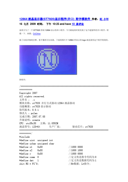
12864液晶显示器(ST7920)显示程序(并口) 附字模软件作者:纪小年16 七月2009 时间:下午10:25 and have 10 条评论前两天写了一个ST7920控制12864显示的串口程序,今天瞎逛的时候发现了这个超强悍的并口程序,转载一下。
来源:CnChina做了比较详细的注释,看不懂的可以问我。
下面的图片中12864所显示的logo就是我用这个程序得到的。
附程序:/******************************************************************** **********Copyright 2007All rights reserved.文件名: .c模块名称:st7920 并行方式驱动12864液晶驱动功能概要:st7920显示驱动取代版本:0.0.1修改人:pulan完成日期:2007.07.08升级说明:createCPU: stc89c58 主频:11.0592M液晶型号:128*64 生产厂家:驱动芯片:st7920********************************************************************* *********/#include#define uint unsigned int#define uchar unsigned char#define x1 0x80 //1000 0000#define x2 0x88 //1000 1000#define y 0x80 //1000 0000#define comm 0 //定义传送指令代码为0#define dat 1 //定义传送数据代码为1sbit RS = P2^0; //H=数据; L=指令;sbit RW = P2^1; //H=读操作; L=写操作;sbit E = P2^3; //使能端sbit PSB= P2^4; //H=并口; L=串口;sbit RST= P2^2; //复位信号低电平有效sbit busy=P0^7; //LCD忙信号void wr_lcd (uchar dat_comm,uchar content);void chk_busy (void);void delay (uint us);uchar code tab1[]={"本系列中文模块内""任意位置反白显示""置二级字库,可在""使用更方便更灵活"};uchar code tab31[]={"金鹏科技有限公司""Golden Palm TECH"};uchar code tab32[]={/*-- 调入了一幅图像:F:\梁\画图\HOCO12832.bmp --*//*-- 宽度x高度=128x32 --*/0x00,0x00,0x00,0x00,0x00,0x00,0x00,0x00,0x00,0x00,0x00,0x00,0x00,0x00 ,0x00,0x00,0x00,0x1E,0x00,0x00,0x00,0x00,0x00,0x07,0xF0,0x00,0x00,0x00,0x00,0x00 ,0x00,0x00,0x00,0x7F,0x80,0x00,0x00,0x00,0x00,0x18,0x0C,0x00,0x00,0x01,0x00,0x00 ,0x00,0x00,0x01,0xFF,0x80,0x00,0x00,0x00,0x00,0x20,0x00,0x00,0x00,0x13,0x10,0x03 ,0xFE,0x00,0x03,0xFF,0xC0,0x00,0x00,0x00,0x00,0x58,0x00,0x00,0x00,0x3F,0x30,0x1F ,0xFF,0xC0,0x03,0xFF,0xE0,0x00,0x00,0x00,0x00,0x8C,0x03,0xF0,0x00,0x7F,0xE0,0x7C ,0x01,0xE0,0x03,0xFF,0xF0,0x00,0x00,0x00,0x01,0x36,0x06,0xC0,0x00,0x5F,0xC0,0xFF ,0xFC,0x60,0x01,0xFF,0xF0,0x00,0x00,0x00,0x02,0x1B,0x0F,0x80,0x00,0xFF,0x01,0xFE ,0x0F,0x30,0x00,0xEF,0xF0,0x00,0x00,0x00,0x02,0x6D,0x9F,0x00,0x00,0x3E,0x03,0xFF ,0xF1,0x90,0x00,0xFF,0xF8,0x00,0x00,0x00,0x04,0x36,0xFE,0x00,0x01,0xFF,0x07,0xFF ,0xFC,0x90,0x00,0xEF,0xFF,0xFF,0x80,0x00,0x04,0xDB,0x7E,0x00,0x03,0xFF,0x87,0xFF ,0xFC,0xD0,0x00,0x0F,0xFF,0xFF,0xC0,0x00,0x04,0x6D,0xFC,0x00,0x07,0xFF,0x8F,0xFF ,0xFE,0x50,0x00,0x0F,0xFF,0xFF,0xE0,0x00,0x04,0x36,0xFC,0x10,0x07,0xFF,0x8F,0xFF ,0xFE,0x90,0x00,0x0F,0xFF,0xFF,0xE0,0x00,0x04,0x1B,0xF8,0x10,0x07,0xFF,0xCF,0xFF ,0xFE,0x80,0x00,0x0F,0xFF,0xFF,0xF0,0x00,0x04,0x0F,0xF8,0x10,0x07,0xFF,0xFF,0xFF ,0xFA,0x00,0x00,0x07,0xFF,0xFF,0xF0,0x00,0x04,0x07,0xF0,0x10,0x07,0xFF,0xFF,0xFF ,0xFA,0x00,0x00,0xFF,0xFF,0xFF,0xF8,0x00,0x02,0x03,0xF0,0x20,0x07,0xFF,0xFF,0xFF ,0xBA,0x00,0x00,0xFD,0xFF,0xFF,0xFC,0x00,0x02,0x03,0xF0,0x20,0x03,0xFF,0xFF,0xDF ,0xB8,0x00,0x00,0xC1,0xC0,0x3F,0xFC,0x00,0x01,0x01,0xE0,0x40,0x00,0xFF,0xFF,0xDF ,0xB0,0x00,0x00,0x81,0xC0,0x3F,0xCE,0x00,0x00,0x81,0xE0,0x80,0x00,0x7F,0xFF,0xDF ,0xA0,0x00,0x00,0x81,0x80,0x1D,0xCF,0x00,0x00,0x41,0xE1,0x00,0x00,0x3F,0xFF,0x9B ,0x00,0x00,0x01,0x83,0x80,0x1F,0xC7,0x80,0x00,0x21,0xE2,0x00,0x00,0x1F,0xFD,0xB6 ,0x00,0x00,0x01,0xC3,0x00,0x0E,0xE6,0x80,0x00,0x19,0xEC,0x00,0x00,0x07,0xFE,0x20 ,0x00,0x00,0x00,0xC3,0x00,0x07,0x67,0x40,0x00,0x07,0xF0,0x00,0x00,0x03,0x3E,0x00 ,0x00,0x00,0x00,0x02,0x00,0x03,0xE7,0xA0,0x00,0x00,0x00,0x00,0x00,0x02,0x8E,0x00 ,0x00,0x00,0x00,0x06,0x00,0x03,0x83,0x00,0x00,0x00,0x00,0x00,0x00,0x02,0x03,0x00 ,0x00,0x00,0x00,0x06,0x00,0x07,0x03,0x00,0x77,0x46,0x74,0x24,0x80,0x06,0x04,0x00 ,0x00,0x00,0x00,0x1C,0x00,0x06,0x00,0x00,0x55,0x45,0x54,0x57,0x80,0x00,0x00,0x00 ,0x00,0x00,0x00,0x1C,0x00,0x0E,0x00,0x00,0x45,0x45,0x74,0x57,0x80,0x08,0x00,0x00 ,0x00,0x00,0x00,0x00,0x00,0x1C,0x00,0x00,0x55,0x45,0x44,0x74,0x80,0xF0,0x00,0x00 ,0x00,0x00,0x00,0x00,0x00,0x38,0x00,0x00,0x77,0x76,0x47,0x54,0x80,0x00,0x00,0x00 ,0x00,0x00,0x00,0x00,0x00,0x00,0x00,0x00,0x10,0x00,0x00,0x00,0x00,0x00,0x00,0x00 ,0x00,0x00};uchar code tab5[]={/*-- 调入了一幅图像:F:\梁\画图\COCK.bmp --*//*-- 宽度x高度=128x64 --*/0x00,0x00,0x00,0x00,0x00,0x00,0x00,0x00,0x00,0x00,0x00,0x00,0x00,0x00 ,0x00,0x00,0x00,0x00,0x00,0x00,0x00,0x00,0x00,0x00,0x00,0x00,0x00,0x00,0x00,0x00 ,0x00,0x00,0x00,0x00,0x00,0x00,0x00,0x00,0x00,0x00,0x00,0x00,0x00,0x00,0x00,0x00 ,0x00,0x00,0x00,0x00,0x00,0x00,0x00,0x00,0x00,0x00,0x00,0x00,0x00,0x00,0x00,0x00 ,0x00,0x00,0x00,0x00,0x00,0x00,0x00,0x00,0x00,0x00,0x00,0x00,0x00,0x00,0x00,0x00 ,0x00,0x00,0x00,0x00,0x00,0x00,0x00,0x01,0x00,0x80,0x00,0x0F,0xFF,0x00,0x00,0x00 ,0x00,0x00,0x00,0x00,0x00,0x00,0x0C,0x43,0x01,0x80,0x00,0x7F,0xFF,0xF0,0x00,0x00 ,0x00,0x00,0x00,0x00,0x00,0x00,0x19,0xFF,0x07,0x00,0x07,0xFF,0xFF,0xFE,0x00,0x00 ,0x00,0x00,0x00,0x00,0x00,0x01,0x3F,0xFC,0x1E,0x00,0x1F,0xFF,0xFF,0xFF,0x80,0x00 ,0x00,0x00,0x00,0x00,0x00,0x01,0xBF,0xFF,0xFC,0x00,0x7F,0xFC,0x00,0x7F,0xC0,0x00 ,0x00,0x00,0x00,0x00,0x00,0x01,0xFF,0xFF,0xF0,0x00,0xFF,0xC0,0x00,0x0F,0xE0,0x00 ,0x00,0x00,0x00,0x00,0x00,0x01,0xFF,0xFF,0xE0,0x03,0xFF,0xFF,0xFC,0x01,0xF0,0x00 ,0x00,0x00,0x00,0x00,0x00,0x01,0xDF,0xFF,0xC0,0x07,0xFF,0xFF,0xFF,0x80,0xF0,0x00 ,0x00,0x00,0x00,0x00,0x00,0x03,0xFF,0xFF,0x00,0x0F,0xFF,0xFF,0xFF,0xE0,0x38,0x00 ,0x00,0x00,0x00,0x00,0x00,0x07,0xFF,0xF8,0x00,0x1F,0xFF,0xF0,0x03,0xF8,0x38,0x00 ,0x00,0x00,0x00,0x00,0x00,0x07,0xFF,0xE0,0x00,0x3F,0xFF,0xFF,0xC0,0x7C,0x18,0x00 ,0x00,0x00,0x00,0x00,0x00,0x04,0x7F,0xF0,0x00,0x3F,0xFF,0xFF,0xF8,0x1E,0x08,0x00 ,0x00,0x00,0x00,0x00,0x00,0x01,0xFF,0xF8,0x00,0x7F,0xFF,0xFF,0xFE,0x0F,0x08,0x00 ,0x00,0x00,0x00,0x00,0x00,0x0F,0xFF,0xFC,0x00,0xFF,0xFF,0xFF,0xFF,0x87,0x08,0x00 ,0x00,0x00,0x00,0x00,0x00,0x1F,0xFF,0xFE,0x00,0xFF,0xFF,0xFF,0xFF,0x83,0x88,0x00 ,0x00,0x00,0x00,0x00,0x00,0x3F,0xFF,0xFE,0x01,0xFF,0xFF,0xFF,0xFF,0xC3,0x88,0x00 ,0x00,0x00,0x00,0x00,0x00,0x7F,0xFF,0xFE,0x01,0xFF,0xFF,0xFF,0xFF,0xE1,0x88,0x00 ,0x00,0x00,0x00,0x00,0x00,0xFF,0xFF,0xFE,0x03,0xFF,0xFF,0xFF,0xFF,0xE1,0x88,0x00 ,0x00,0x00,0x00,0x00,0x01,0xFF,0xFF,0xFE,0x03,0xFF,0xFF,0xFF,0xFF,0xF1,0x88,0x00 ,0x00,0x00,0x00,0x00,0x01,0xFF,0xFF,0xFE,0x03,0xFF,0xFF,0xFF,0xFF,0xF3,0x08,0x00 ,0x00,0x00,0x00,0x00,0x01,0xFF,0xFF,0xFF,0x07,0xFF,0xFF,0xFF,0xFF,0xF2,0x10,0x00 ,0x00,0x00,0x00,0x00,0x01,0xFF,0xFF,0xFF,0x8F,0xFF,0xFF,0xFF,0xFF,0xF0,0x20,0x00 ,0x00,0x00,0x00,0x00,0x01,0xFF,0xFF,0xFF,0xFF,0xFF,0xFF,0xFF,0xFF,0xF0,0x00,0x00 ,0x00,0x00,0x00,0x00,0x01,0xFF,0xFF,0xFF,0xFF,0xFF,0xFF,0xFF,0xFF,0x70,0x00,0x00 ,0x00,0x00,0x00,0x00,0x01,0xFF,0xFF,0xFF,0xFF,0xFF,0xFF,0xFE,0xFF,0x70,0x00,0x00 ,0x00,0x00,0x00,0x00,0x01,0xFF,0xFF,0xFF,0xFF,0xFF,0xFF,0xFE,0xFF,0x70,0x00,0x00 ,0x00,0x00,0x00,0x00,0x00,0xFF,0xFF,0xFF,0xFF,0xFF,0x7F,0xFF,0x7F,0x20,0x00,0x00 ,0x00,0x00,0x00,0x00,0x00,0xFF,0xFF,0xFF,0xFF,0xFF,0xBF,0xFF,0x7F,0x20,0x00,0x00 ,0x00,0x00,0x00,0x00,0x00,0x7F,0xFF,0xFF,0xFF,0xFF,0xDF,0xFF,0x7E,0x20,0x00,0x00 ,0x00,0x00,0x00,0x00,0x00,0x3F,0xFF,0xFF,0xFF,0xFF,0xDF,0xFF,0x3E,0x40,0x00,0x00 ,0x00,0x00,0x00,0x00,0x00,0x1F,0xFF,0xFF,0xFF,0xFF,0xCF,0xFF,0x3C,0x40,0x00,0x00 ,0x00,0x00,0x00,0x00,0x00,0x0F,0xFF,0xFF,0xFF,0xFF,0xCF,0xFE,0x38,0x40,0x00,0x00 ,0x00,0x00,0x00,0x00,0x00,0x07,0xFF,0xFF,0xFF,0xFF,0x8F,0xFE,0x38,0x40,0x00,0x00 ,0x00,0x00,0x00,0x00,0x00,0x01,0xFF,0xFF,0xFF,0xFF,0x8F,0xFE,0x30,0x40,0x00,0x00 ,0x00,0x00,0x00,0x00,0x00,0x00,0xFF,0xFF,0xFF,0xFF,0x1F,0x7C,0x20,0x40,0x00,0x00 ,0x00,0x00,0x00,0x00,0x00,0x00,0x7F,0xFF,0xFF,0xFE,0x1E,0x78,0x00,0x40,0x00,0x00 ,0x00,0x00,0x00,0x00,0x00,0x00,0x3F,0xFF,0xFF,0xFE,0x1E,0xF0,0x00,0x00,0x00,0x00 ,0x00,0x00,0x00,0x00,0x00,0x00,0x1F,0xFF,0xFF,0xDA,0x3C,0xE0,0x00,0x00,0x00,0x00 ,0x00,0x00,0x00,0x00,0x00,0x00,0x07,0xFF,0xFF,0xF2,0x30,0x80,0x00,0x00,0x00,0x00 ,0x00,0x00,0x00,0x00,0x00,0x00,0x01,0xFF,0xFF,0xF1,0x20,0x00,0x00,0x00,0x00,0x00 ,0x00,0x00,0x00,0x00,0x00,0x00,0x00,0xFE,0x7F,0xF0,0x00,0x00,0x00,0x00,0x00,0x00 ,0x00,0x00,0x00,0x00,0x00,0x00,0x00,0x7C,0x3F,0xF0,0x00,0x00,0x00,0x00,0x00,0x00 ,0x00,0x00,0x00,0x00,0x00,0x00,0x00,0x78,0x1F,0xE0,0x00,0x00,0x00,0x00,0x00,0x00 ,0x00,0x00,0x00,0x00,0x00,0x00,0x00,0x72,0x07,0xE0,0x00,0x00,0x00,0x00,0x00,0x00 ,0x00,0x00,0x00,0x00,0x00,0x00,0x00,0x70,0x00,0xE0,0x00,0x00,0x00,0x00,0x00,0x00 ,0x00,0x00,0x00,0x00,0x00,0x00,0x00,0x60,0x00,0x78,0x00,0x00,0x00,0x00,0x00,0x00 ,0x00,0x00,0x00,0x00,0x00,0x00,0x00,0x60,0x00,0x60,0x00,0x00,0x00,0x00,0x00,0x00 ,0x00,0x00,0x00,0x00,0x00,0x00,0x00,0xC0,0x03,0xF0,0x00,0x00,0x00,0x00,0x00,0x00 ,0x00,0x00,0x00,0x00,0x00,0x00,0x01,0x40,0x04,0xD8,0x00,0x00,0x00,0x00,0x00,0x00 ,0x00,0x00,0x00,0x00,0x00,0x00,0x01,0x00,0x01,0x08,0x00,0x00,0x00,0x00,0x00,0x00 ,0x00,0x00,0x00,0x00,0x00,0x00,0x02,0x0C,0x02,0x00,0x00,0x00,0x00,0x00,0x00,0x00 ,0x00,0x00,0x00,0x00,0x00,0x00,0x02,0x40,0x04,0x00,0x00,0x00,0x00,0x00,0x00,0x00 ,0x00,0x00,0x00,0x00,0x00,0x00,0x0C,0x48,0x00,0x00,0x00,0x00,0x00,0x00,0x00,0x00 ,0x00,0x00,0x00,0x00,0x00,0x00,0x38,0x41,0x00,0x00,0x00,0x00,0x00,0x00,0x00,0x00 ,0x00,0x00,0x00,0x00,0x00,0x0F,0xE2,0x00,0x00,0x00,0x00,0x00,0x00,0x00,0x00,0x00 ,0x00,0x00,0x00,0x00,0x00,0x00,0x40,0x00,0x00,0x00,0x00,0x00,0x00,0x00,0x00,0x00 ,0x00,0x00,0x00,0x00,0x00,0x00,0x00,0x00,0x00,0x00,0x00,0x00,0x00,0x00,0x00,0x00 ,0x00,0x00,0x00,0x00,0x00,0x00,0x00,0x00,0x00,0x00,0x00,0x00,0x00,0x00,0x00,0x00 ,0x00,0x00,0x00,0x00,0x00,0x00,0x00,0x00,0x00,0x00,0x00,0x00,0x00,0x00,0x00,0x00 ,0x00,0x00};/******************************************************************** *********************** 函数名称:init_lcd* 功能描述:初始化LCD********************************************************************* *********************/void init_lcd (void){RST = 1;PSB = 1;wr_lcd(comm,0x30); //0011 0000 扩充功能设定——8位数据基本指令操作wr_lcd(comm,0x01); //0000 0001 清屏——将DDRAM填满"20H",并且设定DDRAM的地址计数器为"00H"wr_lcd(comm,0x06); //0000 0110 进入点设定——指定在数据的读取与写入时,设定游标的移动方向wr_lcd(comm,0x0c); //0000 1100 游标或显示移位控制——开显示,关游标}/******************************************************************** *********************** 函数名称:chn_disp* 功能描述:显示汉字或字符********************************************************************* *********************/void chn_disp(uchar code *chn){uchar i,j; //i为横坐标,j为纵坐标wr_lcd(comm,0x30); //0011 0000 扩充功能设定——8位数据基本指令操作wr_lcd(comm,0x80); //1000 0000 设定DDRAM地址——0000000for(j=0;j<4;j++) //写四行数据{for(i=0;i<16;i++)wr_lcd(dat,chn[j*16+i]);}}/******************************************************************** *********************** 函数名称:chn_disp1* 功能描述:上半屏显示汉字或字符********************************************************************* *********************/void chn_disp1(uchar code *chn){uchar i,j;wr_lcd(comm,0x30); //0011 0000 扩充功能设定——8位数据基本指令操作wr_lcd(comm,0x80); //1000 0000 设定第一行的DDRAM 地址——0x80j=0; //第一行for(i=0;i<16;i++)wr_lcd(dat,chn[j*16+i]);wr_lcd(comm,0x90); //1001 0000 设定第二行的DDRAM 地址——0x90j=1; //第二行for(i=0;i<16;i++)wr_lcd(dat,chn[j*16+i]);}/******************************************************************** *********************** 函数名称:img_disp* 功能描述:显示图形********************************************************************* *********************/void img_disp(uchar code *img){uchar i,j;for(j=0;j<32;j++) //绘制上半屏{for(i=0;i<8;i++){wr_lcd(comm,0x34); //0011 0100 扩充功能设定——8位数据扩充指令操作绘图开wr_lcd(comm,y+j); //1xxx xxxx 设定绘图RAM——先设定垂直(列)地址AC6 AC5…AC0wr_lcd(comm,x1+i); //1000 0xxx 设定绘图RAM——再设定水平(行)地址AC3AC2AC1AC0wr_lcd(comm,0x30); //0011 0000 扩充功能设定——8位数据基本指令操作wr_lcd(dat,img[j*16+i*2]);wr_lcd(dat,img[j*16+i*2+1]);}}for(j=32;j<64;j++) //绘制下半屏{for(i=0;i<8;i++){wr_lcd(comm,0x34); //0011 0100 扩充功能设定——8位数据扩充指令操作绘图开wr_lcd(comm,y+j-32); //1xxx xxxx 设定绘图RAM——先设定垂直(列)地址AC6 AC5…AC0wr_lcd(comm,x2+i); //1000 1xxx 设定绘图RAM——再设定水平(行)地址AC3AC2AC1AC0wr_lcd(comm,0x30); //0011 0000 扩充功能设定——8位数据基本指令操作wr_lcd(dat,img[j*16+i*2]);wr_lcd(dat,img[j*16+i*2+1]);}}wr_lcd (comm,0x36); //0011 0110 扩充功能设定——8位数据扩充指令操作绘图关}/******************************************************************** *********************** 函数名称:img_disp1* 功能描述:下半屏显示图形********************************************************************* *********************/void img_disp1(uchar code *img){uchar i,j;for(j=0;j<32;j++){for(i=0;i<8;i++){wr_lcd(comm,0x34);wr_lcd(comm,y+j);wr_lcd(comm,x2+i);wr_lcd(comm,0x30);wr_lcd(dat,img[j*16+i*2]);wr_lcd(dat,img[j*16+i*2+1]);}}wr_lcd(comm,0x36);}/******************************************************************** *********************** 函数名称:lat_disp* 功能描述:显示点阵********************************************************************* *********************/void lat_disp(uchar data1,uchar data2){uchar i,j,k,x;x=x1; //1000 0000for(k=0;k<2;k++) //第一次循环x=1000 0000 第二次循环x=1000 1000{for(j=0;j<16;j++){for(i=0;i<8;i++){wr_lcd(comm,0x34); //0011 0100 扩充功能设定——8位数据扩充指令操作绘图开wr_lcd(comm,y+j*2);wr_lcd(comm,x+i);wr_lcd(comm,0x30);wr_lcd(dat,data1);wr_lcd(dat,data1);}for(i=0;i<8;i++){wr_lcd(comm,0x34);wr_lcd(comm,y+j*2+1);wr_lcd(comm,x+i);wr_lcd(comm,0x30);wr_lcd(dat,data2);wr_lcd(dat,data2);}}x=x2;}wr_lcd(comm,0x36);}/******************************************************************** *********************** 函数名称:con_disp* 功能描述:当data1=0xff,data2=0xff时,在x0,y0处反白显示16xl*yl ********************************************************************* *********************/void con_disp(uchar data1,uchar data2,uchar x0,uchar y0,uchar xl,uchar yl){uchar i,j;for(j=0;j< pre> 。
NuMicro N9H30系列开发板用户手册说明书

NuMicro®FamilyArm® ARM926EJ-S BasedNuMaker-HMI-N9H30User ManualEvaluation Board for NuMicro® N9H30 SeriesNUMAKER-HMI-N9H30 USER MANUALThe information described in this document is the exclusive intellectual property ofNuvoton Technology Corporation and shall not be reproduced without permission from Nuvoton.Nuvoton is providing this document only for reference purposes of NuMicro microcontroller andmicroprocessor based system design. Nuvoton assumes no responsibility for errors or omissions.All data and specifications are subject to change without notice.For additional information or questions, please contact: Nuvoton Technology Corporation.Table of Contents1OVERVIEW (5)1.1Features (7)1.1.1NuMaker-N9H30 Main Board Features (7)1.1.2NuDesign-TFT-LCD7 Extension Board Features (7)1.2Supporting Resources (8)2NUMAKER-HMI-N9H30 HARDWARE CONFIGURATION (9)2.1NuMaker-N9H30 Board - Front View (9)2.2NuMaker-N9H30 Board - Rear View (14)2.3NuDesign-TFT-LCD7 - Front View (20)2.4NuDesign-TFT-LCD7 - Rear View (21)2.5NuMaker-N9H30 and NuDesign-TFT-LCD7 PCB Placement (22)3NUMAKER-N9H30 AND NUDESIGN-TFT-LCD7 SCHEMATICS (24)3.1NuMaker-N9H30 - GPIO List Circuit (24)3.2NuMaker-N9H30 - System Block Circuit (25)3.3NuMaker-N9H30 - Power Circuit (26)3.4NuMaker-N9H30 - N9H30F61IEC Circuit (27)3.5NuMaker-N9H30 - Setting, ICE, RS-232_0, Key Circuit (28)NUMAKER-HMI-N9H30 USER MANUAL3.6NuMaker-N9H30 - Memory Circuit (29)3.7NuMaker-N9H30 - I2S, I2C_0, RS-485_6 Circuit (30)3.8NuMaker-N9H30 - RS-232_2 Circuit (31)3.9NuMaker-N9H30 - LCD Circuit (32)3.10NuMaker-N9H30 - CMOS Sensor, I2C_1, CAN_0 Circuit (33)3.11NuMaker-N9H30 - RMII_0_PF Circuit (34)3.12NuMaker-N9H30 - RMII_1_PE Circuit (35)3.13NuMaker-N9H30 - USB Circuit (36)3.14NuDesign-TFT-LCD7 - TFT-LCD7 Circuit (37)4REVISION HISTORY (38)List of FiguresFigure 1-1 Front View of NuMaker-HMI-N9H30 Evaluation Board (5)Figure 1-2 Rear View of NuMaker-HMI-N9H30 Evaluation Board (6)Figure 2-1 Front View of NuMaker-N9H30 Board (9)Figure 2-2 Rear View of NuMaker-N9H30 Board (14)Figure 2-3 Front View of NuDesign-TFT-LCD7 Board (20)Figure 2-4 Rear View of NuDesign-TFT-LCD7 Board (21)Figure 2-5 Front View of NuMaker-N9H30 PCB Placement (22)Figure 2-6 Rear View of NuMaker-N9H30 PCB Placement (22)Figure 2-7 Front View of NuDesign-TFT-LCD7 PCB Placement (23)Figure 2-8 Rear View of NuDesign-TFT-LCD7 PCB Placement (23)Figure 3-1 GPIO List Circuit (24)Figure 3-2 System Block Circuit (25)Figure 3-3 Power Circuit (26)Figure 3-4 N9H30F61IEC Circuit (27)Figure 3-5 Setting, ICE, RS-232_0, Key Circuit (28)Figure 3-6 Memory Circuit (29)Figure 3-7 I2S, I2C_0, RS-486_6 Circuit (30)Figure 3-8 RS-232_2 Circuit (31)Figure 3-9 LCD Circuit (32)NUMAKER-HMI-N9H30 USER MANUAL Figure 3-10 CMOS Sensor, I2C_1, CAN_0 Circuit (33)Figure 3-11 RMII_0_PF Circuit (34)Figure 3-12 RMII_1_PE Circuit (35)Figure 3-13 USB Circuit (36)Figure 3-14 TFT-LCD7 Circuit (37)List of TablesTable 2-1 LCD Panel Combination Connector (CON8) Pin Function (11)Table 2-2 Three Sets of Indication LED Functions (12)Table 2-3 Six Sets of User SW, Key Matrix Functions (12)Table 2-4 CMOS Sensor Connector (CON10) Function (13)Table 2-5 JTAG ICE Interface (J2) Function (14)Table 2-6 Expand Port (CON7) Function (16)Table 2-7 UART0 (J3) Function (16)Table 2-8 UART2 (J6) Function (16)Table 2-9 RS-485_6 (SW6~8) Function (17)Table 2-10 Power on Setting (SW4) Function (17)Table 2-11 Power on Setting (S2) Function (17)Table 2-12 Power on Setting (S3) Function (17)Table 2-13 Power on Setting (S4) Function (17)Table 2-14 Power on Setting (S5) Function (17)Table 2-15 Power on Setting (S7/S6) Function (18)Table 2-16 Power on Setting (S9/S8) Function (18)Table 2-17 CMOS Sensor Connector (CON9) Function (19)Table 2-18 CAN_0 (SW9~10) Function (19)NUMAKER-HMI-N9H30 USER MANUAL1 OVERVIEWThe NuMaker-HMI-N9H30 is an evaluation board for GUI application development. The NuMaker-HMI-N9H30 consists of two parts: a NuMaker-N9H30 main board and a NuDesign-TFT-LCD7 extensionboard. The NuMaker-HMI-N9H30 is designed for project evaluation, prototype development andvalidation with HMI (Human Machine Interface) function.The NuMaker-HMI-N9H30 integrates touchscreen display, voice input/output, rich serial port serviceand I/O interface, providing multiple external storage methods.The NuDesign-TFT-LCD7 can be plugged into the main board via the DIN_32x2 extension connector.The NuDesign-TFT-LCD7 includes one 7” LCD which the resolution is 800x480 with RGB-24bits andembedded the 4-wires resistive type touch panel.Figure 1-1 Front View of NuMaker-HMI-N9H30 Evaluation BoardNUMAKER-HMI-N9H30 USER MANUAL Figure 1-2 Rear View of NuMaker-HMI-N9H30 Evaluation Board1.1 Features1.1.1 NuMaker-N9H30 Main Board Features●N9H30F61IEC chip: LQFP216 pin MCP package with DDR (64 MB)●SPI Flash using W25Q256JVEQ (32 MB) booting with quad mode or storage memory●NAND Flash using W29N01HVSINA (128 MB) booting or storage memory●One Micro-SD/TF card slot served either as a SD memory card for data storage or SDIO(Wi-Fi) device●Two sets of COM ports:–One DB9 RS-232 port with UART_0 used 75C3232E transceiver chip can be servedfor function debug and system development.–One DB9 RS-232 port with UART_2 used 75C3232E transceiver chip for userapplication●22 GPIO expansion ports, including seven sets of UART functions●JTAG interface provided for software development●Microphone input and Earphone/Speaker output with 24-bit stereo audio codec(NAU88C22) for I2S interfaces●Six sets of user-configurable push button keys●Three sets of LEDs for status indication●Provides SN65HVD230 transceiver chip for CAN bus communication●Provides MAX3485 transceiver chip for RS-485 device connection●One buzzer device for program applicationNUMAKER-HMI-N9H30 USER MANUAL●Two sets of RJ45 ports with Ethernet 10/100 Mbps MAC used IP101GR PHY chip●USB_0 that can be used as Device/HOST and USB_1 that can be used as HOSTsupports pen drives, keyboards, mouse and printers●Provides over-voltage and over current protection used APL3211A chip●Retain RTC battery socket for CR2032 type and ADC0 detect battery voltage●System power could be supplied by DC-5V adaptor or USB VBUS1.1.2 NuDesign-TFT-LCD7 Extension Board Features●7” resolution 800x480 4-wire resistive touch panel for 24-bits RGB888 interface●DIN_32x2 extension connector1.2 Supporting ResourcesFor sample codes and introduction about NuMaker-N9H30, please refer to N9H30 BSP:https:///products/gui-solution/gui-platform/numaker-hmi-n9h30/?group=Software&tab=2Visit NuForum for further discussion about the NuMaker-HMI-N9H30:/viewforum.php?f=31 NUMAKER-HMI-N9H30 USER MANUALNUMAKER-HMI-N9H30 USER MANUAL2 NUMAKER-HMI-N9H30 HARDWARE CONFIGURATION2.1 NuMaker-N9H30 Board - Front View Combination Connector (CON8)6 set User SWs (K1~6)3set Indication LEDs (LED1~3)Power Supply Switch (SW_POWER1)Audio Codec(U10)Microphone(M1)NAND Flash(U9)RS-232 Transceiver(U6, U12)RS-485 Transceiver(U11)CAN Transceiver (U13)Figure 2-1 Front View of NuMaker-N9H30 BoardFigure 2-1 shows the main components and connectors from the front side of NuMaker-N9H30 board. The following lists components and connectors from the front view:NuMaker-N9H30 board and NuDesign-TFT-LCD7 board combination connector (CON8). This panel connector supports 4-/5-wire resistive touch or capacitance touch panel for 24-bits RGB888 interface.Connector GPIO pin of N9H30 FunctionCON8.1 - Power 3.3VCON8.2 - Power 3.3VCON8.3 GPD7 LCD_CSCON8.4 GPH3 LCD_BLENCON8.5 GPG9 LCD_DENCON8.7 GPG7 LCD_HSYNCCON8.8 GPG6 LCD_CLKCON8.9 GPD15 LCD_D23(R7)CON8.10 GPD14 LCD_D22(R6)CON8.11 GPD13 LCD_D21(R5)CON8.12 GPD12 LCD_D20(R4)CON8.13 GPD11 LCD_D19(R3)CON8.14 GPD10 LCD_D18(R2)CON8.15 GPD9 LCD_D17(R1)CON8.16 GPD8 LCD_D16(R0)CON8.17 GPA15 LCD_D15(G7)CON8.18 GPA14 LCD_D14(G6)CON8.19 GPA13 LCD_D13(G5)CON8.20 GPA12 LCD_D12(G4)CON8.21 GPA11 LCD_D11(G3)CON8.22 GPA10 LCD_D10(G2)CON8.23 GPA9 LCD_D9(G1) NUMAKER-HMI-N9H30 USER MANUALCON8.24 GPA8 LCD_D8(G0)CON8.25 GPA7 LCD_D7(B7)CON8.26 GPA6 LCD_D6(B6)CON8.27 GPA5 LCD_D5(B5)CON8.28 GPA4 LCD_D4(B4)CON8.29 GPA3 LCD_D3(B3)CON8.30 GPA2 LCD_D2(B2)CON8.31 GPA1 LCD_D1(B1)CON8.32 GPA0 LCD_D0(B0)CON8.33 - -CON8.34 - -CON8.35 - -CON8.36 - -CON8.37 GPB2 LCD_PWMCON8.39 - VSSCON8.40 - VSSCON8.41 ADC7 XPCON8.42 ADC3 VsenCON8.43 ADC6 XMCON8.44 ADC4 YMCON8.45 - -CON8.46 ADC5 YPCON8.47 - VSSCON8.48 - VSSCON8.49 GPG0 I2C0_CCON8.50 GPG1 I2C0_DCON8.51 GPG5 TOUCH_INTCON8.52 - -CON8.53 - -CON8.54 - -CON8.55 - -NUMAKER-HMI-N9H30 USER MANUAL CON8.56 - -CON8.57 - -CON8.58 - -CON8.59 - VSSCON8.60 - VSSCON8.61 - -CON8.62 - -CON8.63 - Power 5VCON8.64 - Power 5VTable 2-1 LCD Panel Combination Connector (CON8) Pin Function●Power supply switch (SW_POWER1): System will be powered on if the SW_POWER1button is pressed●Three sets of indication LEDs:LED Color DescriptionsLED1 Red The system power will beterminated and LED1 lightingwhen the input voltage exceeds5.7V or the current exceeds 2A.LED2 Green Power normal state.LED3 Green Controlled by GPH2 pin Table 2-2 Three Sets of Indication LED Functions●Six sets of user SW, Key Matrix for user definitionKey GPIO pin of N9H30 FunctionK1 GPF10 Row0 GPB4 Col0K2 GPF10 Row0 GPB5 Col1K3 GPE15 Row1 GPB4 Col0K4 GPE15 Row1 GPB5 Col1K5 GPE14 Row2 GPB4 Col0K6GPE14 Row2GPB5 Col1 Table 2-3 Six Sets of User SW, Key Matrix Functions●NAND Flash (128 MB) with Winbond W29N01HVS1NA (U9)●Microphone (M1): Through Nuvoton NAU88C22 chip sound input●Audio CODEC chip (U10): Nuvoton NAU88C22 chip connected to N9H30 using I2Sinterface–SW6/SW7/SW8: 1-2 short for RS-485_6 function and connected to 2P terminal (CON5and J5)–SW6/SW7/SW8: 2-3 short for I2S function and connected to NAU88C22 (U10).●CMOS Sensor connector (CON10, SW9~10)–SW9~10: 1-2 short for CAN_0 function and connected to 2P terminal (CON11)–SW9~10: 2-3 short for CMOS sensor function and connected to CMOS sensorconnector (CON10)Connector GPIO pin of N9H30 FunctionCON10.1 - VSSCON10.2 - VSSNUMAKER-HMI-N9H30 USER MANUALCON10.3 - Power 3.3VCON10.4 - Power 3.3VCON10.5 - -CON10.6 - -CON10.7 GPI4 S_PCLKCON10.8 GPI3 S_CLKCON10.9 GPI8 S_D0CON10.10 GPI9 S_D1CON10.11 GPI10 S_D2CON10.12 GPI11 S_D3CON10.13 GPI12 S_D4CON10.14 GPI13 S_D5CON10.15 GPI14 S_D6CON10.16 GPI15 S_D7CON10.17 GPI6 S_VSYNCCON10.18 GPI5 S_HSYNCCON10.19 GPI0 S_PWDNNUMAKER-HMI-N9H30 USER MANUAL CON10.20 GPI7 S_nRSTCON10.21 GPG2 I2C1_CCON10.22 GPG3 I2C1_DCON10.23 - VSSCON10.24 - VSSTable 2-4 CMOS Sensor Connector (CON10) FunctionNUMAKER-HMI-N9H30 USER MANUAL2.2NuMaker-N9H30 Board - Rear View5V In (CON1)RS-232 DB9 (CON2,CON6)Expand Port (CON7)Speaker Output (J4)Earphone Output (CON4)Buzzer (BZ1)System ResetSW (SW5)SPI Flash (U7,U8)JTAG ICE (J2)Power ProtectionIC (U1)N9H30F61IEC (U5)Micro SD Slot (CON3)RJ45 (CON12, CON13)USB1 HOST (CON15)USB0 Device/Host (CON14)CAN_0 Terminal (CON11)CMOS Sensor Connector (CON9)Power On Setting(SW4, S2~S9)RS-485_6 Terminal (CON5)RTC Battery(BT1)RMII PHY (U14,U16)Figure 2-2 Rear View of NuMaker-N9H30 BoardFigure 2-2 shows the main components and connectors from the rear side of NuMaker-N9H30 board. The following lists components and connectors from the rear view:● +5V In (CON1): Power adaptor 5V input ●JTAG ICE interface (J2) ConnectorGPIO pin of N9H30Function J2.1 - Power 3.3V J2.2 GPJ4 nTRST J2.3 GPJ2 TDI J2.4 GPJ1 TMS J2.5 GPJ0 TCK J2.6 - VSS J2.7 GPJ3 TD0 J2.8-RESETTable 2-5 JTAG ICE Interface (J2) Function●SPI Flash (32 MB) with Winbond W25Q256JVEQ (U7); only one (U7 or U8) SPI Flashcan be used●System Reset (SW5): System will be reset if the SW5 button is pressed●Buzzer (BZ1): Control by GPB3 pin of N9H30●Speaker output (J4): Through the NAU88C22 chip sound output●Earphone output (CON4): Through the NAU88C22 chip sound output●Expand port for user use (CON7):Connector GPIO pin of N9H30 FunctionCON7.1 - Power 3.3VCON7.2 - Power 3.3VCON7.3 GPE12 UART3_TXDCON7.4 GPH4 UART1_TXDCON7.5 GPE13 UART3_RXDCON7.6 GPH5 UART1_RXDCON7.7 GPB0 UART5_TXDCON7.8 GPH6 UART1_RTSCON7.9 GPB1 UART5_RXDCON7.10 GPH7 UART1_CTSCON7.11 GPI1 UART7_TXDNUMAKER-HMI-N9H30 USER MANUAL CON7.12 GPH8 UART4_TXDCON7.13 GPI2 UART7_RXDCON7.14 GPH9 UART4_RXDCON7.15 - -CON7.16 GPH10 UART4_RTSCON7.17 - -CON7.18 GPH11 UART4_CTSCON7.19 - VSSCON7.20 - VSSCON7.21 GPB12 UART10_TXDCON7.22 GPH12 UART8_TXDCON7.23 GPB13 UART10_RXDCON7.24 GPH13 UART8_RXDCON7.25 GPB14 UART10_RTSCON7.26 GPH14 UART8_RTSCON7.27 GPB15 UART10_CTSCON7.28 GPH15 UART8_CTSCON7.29 - Power 5VCON7.30 - Power 5VTable 2-6 Expand Port (CON7) Function●UART0 selection (CON2, J3):–RS-232_0 function and connected to DB9 female (CON2) for debug message output.–GPE0/GPE1 connected to 2P terminal (J3).Connector GPIO pin of N9H30 Function J3.1 GPE1 UART0_RXDJ3.2 GPE0 UART0_TXDTable 2-7 UART0 (J3) Function●UART2 selection (CON6, J6):–RS-232_2 function and connected to DB9 female (CON6) for debug message output –GPF11~14 connected to 4P terminal (J6)Connector GPIO pin of N9H30 Function J6.1 GPF11 UART2_TXDJ6.2 GPF12 UART2_RXDJ6.3 GPF13 UART2_RTSJ6.4 GPF14 UART2_CTSTable 2-8 UART2 (J6) Function●RS-485_6 selection (CON5, J5, SW6~8):–SW6~8: 1-2 short for RS-485_6 function and connected to 2P terminal (CON5 and J5) –SW6~8: 2-3 short for I2S function and connected to NAU88C22 (U10)Connector GPIO pin of N9H30 FunctionSW6:1-2 shortGPG11 RS-485_6_DISW6:2-3 short I2S_DOSW7:1-2 shortGPG12 RS-485_6_ROSW7:2-3 short I2S_DISW8:1-2 shortGPG13 RS-485_6_ENBSW8:2-3 short I2S_BCLKNUMAKER-HMI-N9H30 USER MANUALTable 2-9 RS-485_6 (SW6~8) FunctionPower on setting (SW4, S2~9).SW State FunctionSW4.2/SW4.1 ON/ON Boot from USB SW4.2/SW4.1 ON/OFF Boot from eMMC SW4.2/SW4.1 OFF/ON Boot from NAND Flash SW4.2/SW4.1 OFF/OFF Boot from SPI Flash Table 2-10 Power on Setting (SW4) FunctionSW State FunctionS2 Short System clock from 12MHzcrystalS2 Open System clock from UPLL output Table 2-11 Power on Setting (S2) FunctionSW State FunctionS3 Short Watchdog Timer OFFS3 Open Watchdog Timer ON Table 2-12 Power on Setting (S3) FunctionSW State FunctionS4 Short GPJ[4:0] used as GPIO pinS4Open GPJ[4:0] used as JTAG ICEinterfaceTable 2-13 Power on Setting (S4) FunctionSW State FunctionS5 Short UART0 debug message ONS5 Open UART0 debug message OFFTable 2-14 Power on Setting (S5) FunctionSW State FunctionS7/S6 Short/Short NAND Flash page size 2KBS7/S6 Short/Open NAND Flash page size 4KBS7/S6 Open/Short NAND Flash page size 8KBNUMAKER-HMI-N9H30 USER MANUALS7/S6 Open/Open IgnoreTable 2-15 Power on Setting (S7/S6) FunctionSW State FunctionS9/S8 Short/Short NAND Flash ECC type BCH T12S9/S8 Short/Open NAND Flash ECC type BCH T15S9/S8 Open/Short NAND Flash ECC type BCH T24S9/S8 Open/Open IgnoreTable 2-16 Power on Setting (S9/S8) FunctionCMOS Sensor connector (CON9, SW9~10)–SW9~10: 1-2 short for CAN_0 function and connected to 2P terminal (CON11).–SW9~10: 2-3 short for CMOS sensor function and connected to CMOS sensorconnector (CON9).Connector GPIO pin of N9H30 FunctionCON9.1 - VSSCON9.2 - VSSCON9.3 - Power 3.3VCON9.4 - Power 3.3V NUMAKER-HMI-N9H30 USER MANUALCON9.5 - -CON9.6 - -CON9.7 GPI4 S_PCLKCON9.8 GPI3 S_CLKCON9.9 GPI8 S_D0CON9.10 GPI9 S_D1CON9.11 GPI10 S_D2CON9.12 GPI11 S_D3CON9.13 GPI12 S_D4CON9.14 GPI13 S_D5CON9.15 GPI14 S_D6CON9.16 GPI15 S_D7CON9.17 GPI6 S_VSYNCCON9.18 GPI5 S_HSYNCCON9.19 GPI0 S_PWDNCON9.20 GPI7 S_nRSTCON9.21 GPG2 I2C1_CCON9.22 GPG3 I2C1_DCON9.23 - VSSCON9.24 - VSSTable 2-17 CMOS Sensor Connector (CON9) Function●CAN_0 Selection (CON11, SW9~10):–SW9~10: 1-2 short for CAN_0 function and connected to 2P terminal (CON11) –SW9~10: 2-3 short for CMOS sensor function and connected to CMOS sensor connector (CON9, CON10)SW GPIO pin of N9H30 FunctionSW9:1-2 shortGPI3 CAN_0_RXDSW9:2-3 short S_CLKSW10:1-2 shortGPI4 CAN_0_TXDSW10:2-3 short S_PCLKTable 2-18 CAN_0 (SW9~10) Function●USB0 Device/HOST Micro-AB connector (CON14), where CON14 pin4 ID=1 is Device,ID=0 is HOST●USB1 for USB HOST with Type-A connector (CON15)●RJ45_0 connector with LED indicator (CON12), RMII PHY with IP101GR (U14)●RJ45_1 connector with LED indicator (CON13), RMII PHY with IP101GR (U16)●Micro-SD/TF card slot (CON3)●SOC CPU: Nuvoton N9H30F61IEC (U5)●Battery power for RTC 3.3V powered (BT1, J1), can detect voltage by ADC0●RTC power has 3 sources:–Share with 3.3V I/O power–Battery socket for CR2032 (BT1)–External connector (J1)●Board version 2.1NUMAKER-HMI-N9H30 USER MANUAL2.3 NuDesign-TFT-LCD7 -Front ViewFigure 2-3 Front View of NuDesign-TFT-LCD7 BoardFigure 2-3 shows the main components and connectors from the Front side of NuDesign-TFT-LCD7board.7” resolution 800x480 4-W resistive touch panel for 24-bits RGB888 interface2.4 NuDesign-TFT-LCD7 -Rear ViewFigure 2-4 Rear View of NuDesign-TFT-LCD7 BoardFigure 2-4 shows the main components and connectors from the rear side of NuDesign-TFT-LCD7board.NuMaker-N9H30 and NuDesign-TFT-LCD7 combination connector (CON1).NUMAKER-HMI-N9H30 USER MANUAL 2.5 NuMaker-N9H30 and NuDesign-TFT-LCD7 PCB PlacementFigure 2-5 Front View of NuMaker-N9H30 PCB PlacementFigure 2-6 Rear View of NuMaker-N9H30 PCB PlacementNUMAKER-HMI-N9H30 USER MANUALFigure 2-7 Front View of NuDesign-TFT-LCD7 PCB PlacementFigure 2-8 Rear View of NuDesign-TFT-LCD7 PCB Placement3 NUMAKER-N9H30 AND NUDESIGN-TFT-LCD7 SCHEMATICS3.1 NuMaker-N9H30 - GPIO List CircuitFigure 3-1 shows the N9H30F61IEC GPIO list circuit.Figure 3-1 GPIO List Circuit NUMAKER-HMI-N9H30 USER MANUAL3.2 NuMaker-N9H30 - System Block CircuitFigure 3-2 shows the System Block Circuit.NUMAKER-HMI-N9H30 USER MANUALFigure 3-2 System Block Circuit3.3 NuMaker-N9H30 - Power CircuitFigure 3-3 shows the Power Circuit.NUMAKER-HMI-N9H30 USER MANUALFigure 3-3 Power Circuit3.4 NuMaker-N9H30 - N9H30F61IEC CircuitFigure 3-4 shows the N9H30F61IEC Circuit.Figure 3-4 N9H30F61IEC CircuitNUMAKER-HMI-N9H30 USER MANUAL3.5 NuMaker-N9H30 - Setting, ICE, RS-232_0, Key CircuitFigure 3-5 shows the Setting, ICE, RS-232_0, Key Circuit.NUMAKER-HMI-N9H30 USER MANUALFigure 3-5 Setting, ICE, RS-232_0, Key Circuit3.6 NuMaker-N9H30 - Memory CircuitFigure 3-6 shows the Memory Circuit.NUMAKER-HMI-N9H30 USER MANUALFigure 3-6 Memory Circuit3.7 NuMaker-N9H30 - I2S, I2C_0, RS-485_6 CircuitFigure 3-7 shows the I2S, I2C_0, RS-486_6 Circuit.NUMAKER-HMI-N9H30 USER MANUALFigure 3-7 I2S, I2C_0, RS-486_6 Circuit3.8 NuMaker-N9H30 - RS-232_2 CircuitFigure 3-8 shows the RS-232_2 Circuit.NUMAKER-HMI-N9H30 USER MANUALFigure 3-8 RS-232_2 Circuit3.9 NuMaker-N9H30 - LCD CircuitFigure 3-9 shows the LCD Circuit.NUMAKER-HMI-N9H30 USER MANUALFigure 3-9 LCD Circuit3.10 NuMaker-N9H30 - CMOS Sensor, I2C_1, CAN_0 CircuitFigure 3-10 shows the CMOS Sensor,I2C_1, CAN_0 Circuit.NUMAKER-HMI-N9H30 USER MANUALFigure 3-10 CMOS Sensor, I2C_1, CAN_0 Circuit3.11 NuMaker-N9H30 - RMII_0_PF CircuitFigure 3-11 shows the RMII_0_RF Circuit.NUMAKER-HMI-N9H30 USER MANUALFigure 3-11 RMII_0_PF Circuit3.12 NuMaker-N9H30 - RMII_1_PE CircuitFigure 3-12 shows the RMII_1_PE Circuit.NUMAKER-HMI-N9H30 USER MANUALFigure 3-12 RMII_1_PE Circuit3.13 NuMaker-N9H30 - USB CircuitFigure 3-13 shows the USB Circuit.NUMAKER-HMI-N9H30 USER MANUALFigure 3-13 USB Circuit3.14 NuDesign-TFT-LCD7 - TFT-LCD7 CircuitFigure 3-14 shows the TFT-LCD7 Circuit.Figure 3-14 TFT-LCD7 CircuitNUMAKER-HMI-N9H30 USER MANUAL4 REVISION HISTORYDate Revision Description2022.03.24 1.00 Initial version NUMAKER-HMI-N9H30 USER MANUALNUMAKER-HMI-N9H30 USER MANUALImportant NoticeNuvoton Products are neither intended nor warranted for usage in systems or equipment, anymalfunction or failure of which may cause loss of human life, bodily injury or severe propertydamage. Such applications are deemed, “Insecure Usage”.Insecure usage includes, but is not limited to: equipment for surgical implementation, atomicenergy control instruments, airplane or spaceship instruments, the control or operation ofdynamic, brake or safety systems designed for vehicular use, traffic signal instruments, all typesof safety devices, and other applications intended to support or sustain life.All Insecure Usage shall be made at customer’s risk, and in the event that third parties lay claimsto Nuvoton as a result of customer’s Insecure Usage, custome r shall indemnify the damagesand liabilities thus incurred by Nuvoton.。
HPc安装指南

HARDWARE-ACCELERATED
Revolutionary Visual Computing SolutionsHardware-Accelerated Pixel Read-Back Ultra-fast pixel read-back performance delivers massive host throughput, more than 10x the performance of previous generations of graphics systems.GPU ComputingNVIDIA CUDA provides a C languageenvironment and tool suite that unleashes new capabilities to solve complex, visualization challenges such as real-time ray tracing and interactive volume rendering.1NVIDIA PureVideo TechnologyNVIDIA PureVideo ™ technology is the combination of high-definition video processors and software that deliversunprecedented picture clarity, smooth video, accurate color, and precise image scaling for SD and HD video content. Featuresinclude, high-quality scaling, spatial temporal de-interlacing, inverse telecine, and high quality HD video playback from DVD.Features and BenefitsFull 128-Bit Precision Graphics Pipeline Enables mathematical computations to maintain high accuracy, resulting in unmatched visual quality.High-Quality Full-Scene Antialiasing (FSAA)Up to 32x FSAA dramatically reduces visual aliasing artifacts or “jaggies” at resolutions up to 2560 x 1600, resulting in highly realistic scenes. New rotated-grid FSAA algorithm (RG FSAA) delivers unprecedented quality and performance.High Precision, High Dynamic Range Imaging (HDR)Sets new standards for image clarity and quality through floating point capabilities in shading, filtering, texturing, and blending. Enables unprecedented quality of rendered images for visual effects processing.NVIDIA Unified ArchitectureIndustry’s first unified architecture designed to dynamically allocate geometry, shading, pixel, and compute processing power to deliver optimized GPU performance.1Dual Dual-Link Digital Display Connectors Dual dual-link TMDS transmitters support ultra-high-resolution panels (up to 2560 x 1600 @ 60Hz on each panel) − which result in amazing image quality producing detailed photorealistic images.3Essential for Microsoft Windows Vista Offering an enriched 3D user interface,increased application performance, and the highest image quality, NVIDIA Quadro graphics boards and NVIDIA ® OpenGL ICD drivers are optimized for 32- and 64-bit architectures to enable the best Windows ® Vista ™ experience.Technical SpecificationsNVIDIA QUADRO WORKSTATION GPU > 12-bit subpixel precision > Up to 128 textures per pass > Eight (8) multiple render targets > Fast 3D texture support > Jumbo (8K) texture support> Hardware-accelerated antialiased points and lines> Hardware OpenGL overlay planes> Hardware-accelerated two-sided lighting > Hardware-accelerated clipping planes > Third-generation occlusion culling > OpenGL quad-buffered stereo (3-pin sync connector)> Hardware-accelerated pixel read-back NEXT-GENERATION SHADING ARCHITECTURE> Full Shader Model 4.0 (OpenGL and DirectX 10) o Vertex Shader 4.0 o Geometry Shader 4.0 o Pixel Shader 4.0> Unlimited Shader Lengths> FP32 texture filtering and blending > Non-power-of-two texture supportNVIDIA CUDA Software Development Tools > C language compiler, profiler and emulation mode for debugging> Standard numerical libraries for FFT (Fast Fourier Transform) and BLAS (Basic Linear Algegra Subroutines)HIGH-LEVEL SHADER LANGUAGES > Optimized compilers for Cg, OpenGLSL, and Microsoft HLSL > OpenGL 2.1 and DirectX 10 support > Open source compilerHIGH-RESOLUTION ANTIALIASING > Up to 32x full-scene antialiasing (FSAA), up to 2560 x 1600> Rotated-grid FSAA significantly increases color accuracy and visual quality for edges, while maintaining performance UNIFIED DRIVER ARCHITECTURE > Single driver supports all products SUPPORTED PLATFORMS> Microsoft Windows ® Vista, XP, 2000 > Linux—Full OpenGL implementation, complete with NVIDIA and ARBextensions (complete XFree 86 drivers)> AMD64, Intel EM64TPROFESSIONAL CERTIFICATIONS Computer-Aided Design (CAD) /Computer-Aided Manufacturing (CAM) /Computer-Aided Engineering (CAE) Applications > AutoCAD > CATIA > DeltaGen > Inventor > PDMS > PLM> Pro / ENGINEER > Revit> Solid Edge > SolidWorks> and many more…Digital Content Creation (DCC) and Broadcast > 3ds Max > After Effects > Houdini > Illustrator > Lightwave > Maya> Premiere Pro > Softimage | XSI > and many more…Energy> Landmark> Paradigm GEO > Schlumberger Medical/Life Sciences > Accelyris > Tripos> Vital Images1 Available on NVIDIA Quadro FX 5600, 4700 X2, 3700, 1700, 570, 370, 3600M, 1600M, 570M, and 360M.2 Available on NVIDIA Quadro FX 5600, 5500, 4700 X2, 4600, 4500, 3700, 3500, and 3450.3 Available on NVIDIA Quadro FX 5600, 5500, 4700 X2, 4600, 3700, 3500, 1700, and 1500.For more information about NVIDIA Quadro, visit © 2007 NVIDIA Corporation. All rights reserved. NVIDIA, the NVIDIA logo, NVIDIA Quadro, Cuda, and SLI are trademarks and/or registered trademarks of NVIDIA Corporation.All company and product names are trademarks or registered trademarks of the respective owners with which they are associated. Features, pricing, availability, and specifications are all subject to change without notice. Images courtesy of Right Hemisphere, Landmark, UVPHACTORY, NVIDIA Corporation, and Vital Images,The industry’s leading workstation applications leverage these solutions to enable hardware-accelerated features not found in any other professional graphics solution.The Quadro professional products include a set of industry specialtysolutions that have been architected to enable advanced imaging visualization and broadcast applications - from multi-system scalability andsynchronization to uncompressed 12-bit HD-SDI video output.The NVIDIA Quadro ® family of professional solutionstakes the leading professional applications to a new level of interactivity by enabling unprecedented capabilities.Images courtesy of Right Hemisphere, Landmark, a brand of the Halliburton Drilling, Evaluation and Digital Solutions, UVPHACTORY, and Vital Images, Volvo Image Copyright © 2006 MFX / Percival Productions. www.mfx.se.NVIDIA Quadro Family | Sep 2007Ground-breaking Unified Architecture Delivers Unprecedented Performance The latest NVIDIA Quadro architecture takes application performance tonew levels by featuring the industry’sfirst unified architecture1. Designed to dynamically allocate geometry, shading, pixel, and compute processing power, the latest NVIDIA Quadro graphics boards deliver optimized Graphics Processing Unit (GPU) performance. The GPU pipeline efficiency is further multipliedby fast 3D and large texture transfers, NVIDIA’s crossbar memory architecture, enabling occlusion culling, lossless depth Z-buffer, and color compression. These elements combine to achieveunprecedented 3D performance: blazinggeometry performance, lightening-fastline performance and massive fill ratespowered by a dynamically configurablearray of thread processors. With ultra-fast pixel read-back performance,massive host throughput gains can beachieved for professional applications.However, the true measure of power isapplication performance and the newNVIDIA Quadro architecture doubles theperformance of the previous generation.Advanced ProgrammabilityEmpowers a New Classof ApplicationsThe latest NVIDIA Quadro FX graphicssolutions are the reference standard forShader Model 4.0 and next generationoperating systems enabling breakthroughultra-realistic, real-time visualizationapplications. Styling and productionrendering are integral functions of thedesign workflow and NVIDIA QuadroFX provides professionals the toolsto shorten the production processand enable faster time to market.The major CAD and DCC applicationvendors can take full advantage of theprogrammable NVIDIA Quadro architectureby enabling sophisticated shaders tosimulate a virtually unlimited range ofphysical characteristics, such as lightingeffects (dispersion, reflection, refraction,BRDF models) and even physical surfaceproperties (casting effects, porosity,molded surfaces). Real-time shaders allowaccurately matching visual images.All images have a smoother, moreappealing variation in color density, whichincreases visual realism and generatesphotorealistic rendered images.Certified for the HighestQuality Experience withthe Most DemandingWorkstation ApplicationsThe performance and power of theNVIDIA Quadro architecture arebuilt on a solid foundation of qualityengineering. This engineering excellenceis exemplified by the NVIDIA UnifiedDriver Architecture (UDA), which iscertified for quality by the entire spectrumof CAD and DCC applications.these effects to be combined and modifiedinteractively, something that is impossiblewith simple 2D static texture maps.Full 128-bit Floating PointPrecision Delivers the Industry’sHighest Workstation QualitySophisticated real-time effects typicallyinvolve multiple mathematical operations thatdemand high precision to maintain imagequality. The NVIDIA Quadro architecturefeatures true 128-bit IEEE floating pointprecision (32-bit fp per component),resulting in the highest level of accuracyand the ultimate in visual quality.The NVIDIA Quadro family delivers true16-bit and 32-bit floating point formats forThe Definition of Performance. The Standard for Quality.uncompromisedprofessional graphics to goThe NVIDIA Quadro FX professional solutions for mobile workstations deliver the fastest application performanceand the highest quality graphics. The NVIDIA Quadro FX mobile solutions enable the leading CAD, DCC, and visualization applications to solve the most complex professional visual computing challenges in a mobile form factor.integrated graphics to video solutionThe NVIDIA Quadro SDI solutions are ideal foron-air broadcast professionals across manyapplications, including virtual-set, sports, andweather news systems. The NVIDIA Quadro SDIsolution is the industry’s only fully integratedgraphics to video out product, and will compositelive video footage onto virtual backgrounds andsend the result to live video for TV broadcast. Thesolution also allows film production and post-production professionals to preview the results of3D compositing, editing, and color grading in realtime on HD broadcast monitors.c programming environmentfor the gpuThe NVIDIA CUDA™software development kitprovides a C language environment and toolssuite that unleashes new capabilities to solvecomplex, visualization challenges such asreal-time ray tracing and interactive volumerendering.1revolutionizingadvanced visualizationThe NVIDIA Quadro G-Sync deliversframe and genlock functionality tounprecedented levels of industrialrealism, visualization, and collaborativecapabilities. The NVIDIA Quadro G-Sync IIoption can be combined with the QuadroFX 5600 or 4600, and G-Sync I can becombined with the FX 5500 to provideadvanced multi-system visualizationand external signal synchronization.a quantum leap in visual computingThe NVIDIA Quadro Plex is a dedicatedvisual computing system (VCS) enablingbreakthrough levels of capability andproductivity for professionals ranging frommanufacturing designers and stylists toearth scientists to digital content creators.NVIDIA Quadro Plex provides the flexibility tobe deployed with any certified PCI Express®x16 platform. NVIDIA Quadro Plex achievesunmatched compute density, can bedeployed in a wide range of environments,and scales to meet the most demandingprofessional applications requirements.HP Mobile Workstation courtesy HP - image on screen courtesy ProE2000. Racetrack image © Sam Sharpe / The Sharpe Image / Corbis. Inside right page: Geographic imagery courtesy Landmark, a brand of the Halliburton Drilling, Evaluation and Digital Solutions. Video Wall image courtesy ORNL.scalable graphics performance NVIDIA Quadro graphics solutions feature NVIDIA® SLI™ multi-GPU technology2.A revolutionary platform innovation,SLI technology enables professional users to dynamically scale graphics performance, enhance image quality, and expand display real estate by combining multiple NVIDIA Quadro graphics solutions in a single system.Available NVIDIA Quadro Solutions Ultra-High-EndNVIDIA Quadro FX 5600 NVIDIA Quadro FX 5500 NVIDIA Quadro FX 4700 X2 High-EndNVIDIA Quadro FX 4600 NVIDIA Quadro FX 3700 NVIDIA Quadro FX 3500Mid-RangeNVIDIA Quadro FX 3450 NVIDIA Quadro FX 1700 NVIDIA Quadro FX 1500 Entry-LevelNVIDIA Quadro FX 570 NVIDIA Quadro FX 560 NVIDIA Quadro FX 550 NVIDIA Quadro FX 370 SpecialtyNVIDIA Quadro Plex VCS NVIDIA Quadro SDINVIDIA Quadro G-Sync MobileNVIDIA Quadro FX 3600M NVIDIA Quadro FX 1600M NVIDIA Quadro FX 570M NVIDIA Quadro FX 360M。
hp openview performance insight 安装指南说明书

HP OpenView Performance Insight安装指南软件版本: 5.1适用于 HP-UX、Linux、Solaris 和 Windows 操作系统生产部件号:J5223-960392005 年 2 月Copyright 2005 Hewlett-Packard Development Company, L.P.法律声明保证惠普公司对与本文档相关的内容不提供任何性质的保证,包括但不限于暗含的有关适销和符合特定用途的保证。
惠普公司对本手册中包含的错误或因提供、执行或使用本手册导致的直接、间接、特殊、偶发或衍生性损失不负任何责任。
可以从当地销售与服务机构索取适用于您所购买的惠普产品的特定保证条款的副本。
有限权利的说明美国政府使用、复制或披露本文档中的内容均受美国法律编号第 DFARS 252.227-7013 关于“技术数据和计算机软件权利”(Rights in Technical Data and Computer Software)条款的第 (c) (1) (ii) 项的规定。
Hewlett-Packard CompanyUnited States of America非美国国防部的美国政府部门和机构的权利均受美国法律编号第 FAR 52.227-19 的第 (c) (1) 和 (2) 项的规定的限制。
版权声明© Copyright 1992-2005 Hewlett-Packard Development Company, L.P.未经惠普公司事先书面许可,严禁对本文档的任何部分进行复制、转录或翻译成任何其它语言。
本文档所提供的信息如有更改,恕不另行通知。
商标声明Java™是 Sun Microsystems, Inc. 在美国和/或其它国家或地区的美国商标。
MS-DOS indows® 和 Windows NT® 是 Microsoft® Corp. 在美国的注册商标,OpenView 是惠普公司在美国的注册商标。
约翰迪尔第4代显示屏软件更新说明说明书

软件更新第 4 代 操作系统安装时间:在无现有数据的情况下,大约需要 20 分钟。
安装时间取决于现有数据的大小及显示屏上现有的软件版本。
下列第 4 代显示器可通过无线方式或使用 U 盘和“约翰迪尔软件管理器”下载并安装最新软件包,可访问 ,在“软件更新”页获取软件包。
如果在第 4 代显示器上使用“在线显示器软件更新”,则通过无线方式下载软件的时间长短因蜂窝信号覆盖强度或无线互联网连接强度而异。
如需更多帮助,请参考“下载指南”。
通过无线方式重新编程 -https://youtu.be/XSG7O3_9KGI?list=PL1KGsSJ4CWk4fhvFOaBZz261XGwPfXvqk注:第 4 代操作系统软件更新将自动安装相应的第 4 代操作系统帮助文件。
一项更新无法与另一项更新分开。
机器应用软件更新机器应用软件位于第 4 代显示器菜单上的“机器设置”中。
机器应用软件更新需要由约翰迪尔经销商使用 Service ADVISOR™ 安装。
发布说明内容新功能和改进通用信息培训软件包版本第 4 代 操作系统10.16.1400-91第 4 代 操作系统帮助文件10.4.63-10AMS 应用程序10.16.1400-91新功能和改进屏幕操作手册 -• 在显示器上的“帮助中心”应用程序中,新增了第4 代显示器的《操作手册》。
这部分内容将根据将来软件的更新需要而继续更新。
补充的屏幕帮助内容,可从“帮助中心”获得。
注:操作前,请认真阅读最新的《操作手册》。
如需最新版手册,请与经销商联系或访问。
导航 -• 驾驶员现在能在导航应用程序中创建“直线轨迹”和 “AB 曲线”的复制轨迹。
“复制轨迹”用来复制当前处于激活状态的导航轨迹。
新的复制轨迹的名称默认为是原始轨迹的名称加上(1)。
例如,轨迹“West”的复制轨迹的默认名称为 “West(1)”。
选择轨迹名称输入框修改轨迹名称。
新轨迹可以在机器上居中,或者向左或向右变换位置。
DeviceMaster 设备更新指南说明书

Using PortVision Plus to Update DeviceMaster FirmwareThis manual contains the basic steps necessary to completely update NS-Link or SocketServer firmware and Bootloader in the DeviceMaster using PortVision Plus.In the event a failure of these procedures is experienced, it is recommended that Comtrol Technical Support be contacted for additional assistance. This document does not include instructions for configuring security in the DeviceMaster.This manual will show step-by-step instructions for this procedure when using the Microsoft Windows Operating Systems.This manual contains no explanations for the procedures outlined here. For full information and details, please see the DeviceMaster user guide and the DeviceMaster NS-Link user guide.DeviceMaster user guide: ftp:///dev_mstr/rts/docs/dev_mstr_install_guide.pdfDeviceMaster NS-Link user guide: ftp:///dev_mstr/rts/docs/ns-link_user.pdfFor new installations see all of the chapters. For an update situation you may already have PortVision Plus installed and IP addresses assigned to the DeviceMaster. If that is the case, you may skip some of the chapters as desired, but it is recommended that you save your DeviceMaster configurations in any event.Please note: Screen shots showing version numbers will not be correct and are shown as examples.Chapters:Chapter 1: PortVision Plus Installation Page 2Chapter 2: PortVision Plus DeviceMaster Discovery Page 4Chapter 3: Save the DeviceMaster Configuration to a File Page 5Chapter 4: Configure the DeviceMaster IP information Page 7Chapter 5: Setting the Timeout Value in the DeviceMaster Page 9Chapter 6: Updating the Firmware Page 12Chapter 7: Load the DeviceMaster Configuration from a File Page 16Chapter 8: Reset the Timeout Value in the DeviceMaster Page 18Chapter 9: Instructions Revision History Page 19Begin by downloading the desired files by clicking on the links and saving to a convenient directory.PortVision Plus: ftp:///legacy/dev_mstr/portvision_plus/pvplus_v4.08.msiPortVision Plus Help and User Guides: ftp:///legacy/dev_mstr/portvision_plus/docs.exeThe current version of SocketServer may be downloaded using this link:ftp:///dev_mstr/rts/software/socketserver/You will see a file in this folder called socketserver-#.##.bin (replace #'s with numbers)The current version of Bootloader may be downloaded using this link:ftp:///dev_mstr/rts/software/bootloader/You will see a file in this folder called bootloader-#.##.bin (replace #'s with numbers)Please note: SocketServer and NS-Link have been incorporated into a single bin (binary) file. By default, once loaded, the file will show SocketServer in both the web page and PortVision Plus until a driver begins communication with this DeviceMaster. Once a driver establishes communications, the firmware will now indicate that it is NS-Link.Common Application Firmware files for the DeviceMaster UP are also available and may be downloaded from the Comtrol web site: It will be necessary that the PC and the DeviceMaster both have static IP addresses assigned so as to allow full IP communications. Ideally this will be a direct connection between the PC and the DeviceMaster in which case DHCP will not be able to assign IP addresses to either the PC or DeviceMaster. If the update procedure fails, it will be necessary to have IP addresses assigned to both the PC and the DeviceMaster. If the DeviceMaster is to be updated while attached to a network, the Bootloader Timeout value may have to be modified which can only be done using IP communications. Please note: It is mandatory that all security protocols on the DeviceMaster be disabled before beginning this procedure. If desired, after completion, the secure config option may be reselected from the DeviceMaster home page > Configure Security options. Do not select the ‘Secure Data’ mode as this is not compatible with the driver installed in the PC.PortVision Plus InstallationBack to topIf a previous version of PortVision Plus is currently installed, uninstall it by going to Control Panel>Add or Remove Programs. Select PortVision from the list and click on ‘Remove’.Note: If running Windows 2000, current versions of PortVision Plus will not install. You must use this version (or earlier) of PortVision Plus in Windows 2000:ftp:///contribs/devicemaster/portvision/windows_2000_version/pvplus_v3.08.msiRun the pvplus_v4.xx.msi file.Select Next Select the "I accept…" and click 'Next'Accept the default and click 'Next' You will get the option to create a desktop shortcut.Select NextSelect Install Files will now copy and the application will register itselfto the systemSelect No to download the current DeviceMaster User Guides and Help files.The documentation files have already been downloaded. Install the Documentation manually to PortVision Plus by running the docs.exe file downloaded earlier. This file will extract the user guides and manuals to the default PortVision Plus destination directory of "C:\Program Files\Comtrol\PortVision Plus" and add a \Docs sub-directory to this directory. If you have changed the installation of PortVision Plus to a different location, the extraction path must be modified accordingly for the help files to display properly.Click Finish You will now have a PortVision Plusicon on the desktopPortVision Plus DeviceMaster DiscoveryBack to topConnect an Ethernet patch cable directly from the NIC in the PC/laptop to the DeviceMaster.If the DeviceMaster has both an UP and DOWN Ethernet port, connect the patch cable to the DOWN port.If only a single Ethernet port is on the DeviceMaster, then it will auto sense the type of cable used. Do not have any routers, switches or hubs between the PC and the DeviceMaster. This will facilitate the safest and most reliable update process.Please note: Do not set any security options on the DeviceMaster until scanned into PortVision Plus as doingso will prevent PortVision Plus from being able to discover that DeviceMaster.Start PortVisionPlusSelect the “Scan” icon on launch bar.Select YesYour line item(s) may be slightly different depending on the hardware, version of software, IP address assigned, etc. Note the IP address. You will be using IP to communicate to the DeviceMaster. The IP address must be compatible with the IP address assigned to the PC. If you do not see the DeviceMaster listed, click the “Scan” icon on the launch bar.Save the DeviceMaster Configuration to a FileBack to topSaving the configuration is highly recommended. When uploading new firmware over earlier versions, the configuration information may be lost. If this is a new install and the DeviceMaster has never been configured, this chapter may be skipped and you should proceed to the next chapter.Please Note:PortVision Plus will not be able to save the DeviceMaster configuration file when the version number of SocketServer/NS-Link is greater than version 8.99. In this situation PortVision DX MUST be used.Highlight the DeviceMaster and click the ‘Save’ icon on the launch bar.Input a file name and click SaveYou will be presented an options window to select the fields you wish saved.Selecting the ‘All” op tion will save every field.When This window displays some of the fields with the “All” option. restoring or ‘Loading’ the configuration, the same selected. Click ‘Done’ when ready.options will be shown so you may select what fields torestore. Different options will be seen for different typesof firmware, so your screen may not be as shown here.You should see this confirmation dialog.This will be displayed if no field has been selected aboveConfigure the DeviceMaster IP informationBack to topHighlight the 1st line item and then “Double Click” it to open the IP programming pages.The IP Programming window will open.Modify the IP Address, Subnet Mask and Gateway address for compatibility with your network.Once the values have been entered, select ‘Apply Changes’ and then select ‘Close’.The DeviceMaster will now reboot to set the new IP information. This example uses aNetwork of 192.168.2.x addresses,The new IP address should now display and the DeviceMaster will be rebooting as seen in the “Status”. Repeat for additional units.Setting the Timeout Value in the DeviceMasterBack to topHighlight the line item as shown (version numbers shown in screen shots may be different)Using the Device drop down menu (or right click on the DeviceMaster) select Telnet / SSH Session.Click “OK” leaving the Selected Port set to the default 23.A Telnet window will open to a Password prompt as shown on the next page.Please note: The following screen shots are shown using the telnet application included in WindowsXP. PortVision Plus now includes PUTTY as the telnet application as there are now several versions of Windows that do not, by default, install the telnet application. This difference will not affect the text seen in the window.Please note: Version numbers displayed will be different than shown in these examples.If no password has been assigned, press the ‘Enter’ key. If a password has been assigned to this DeviceMaster enter the password and press the ‘Enter’ key.You should now see something like the screen above. The prompt may indicate dm> or RedBoot>. Either prompt is acceptable.Type in Timeout 45, Press EnterYou should see the value confirmedType in ‘q’ and press EnterThe Telnet window will close.Please note:If you have installed the DeviceMaster driver in your system, you will want to disable the driver to prevent possible conflicts while using PortVision Plus to update the firmware. Open Windows DeviceManager and expand the Multi-port serial adapters category . Right click on the DeviceMaster that is having its firmware updatedFrom the pop-up menu, select “Disable”Select OK in the pop-up dialog window.Repeat for each DeviceMaster that is to have the firmware updated.Close Windows DeviceManager. You will return later to enable the driver.Updating the FirmwareBack to topYour line item (highlighted entry) may be slightly different depending on the hardware, version of software, IP address assigned, etc.Highlight the line item and select the 'Upload’ icon from the launch bar.Path out to the firmwares’ .bin file locationNOTE: Upload the application firmware file FIRST! This is critical! Application firmware is all firmware files OTHER than Bootloader. Bootloader is NOT an application file.This example will use SocketServer, but it could also be NS-Link or EthernetIP for a DeviceMaster UP model.Select 'Open'Screen shots do NOT show current versions.Read the confirmation message and select 'Yes'During this process you may receive notifications from the Windows Operating System thatthe Ethernet connection has been lost or that a network cable is unplugged.This is normal and expected so please disregard these notices.Once uploading has completed the following screen will show.Click 'OK'If you now refresh the DeviceMaster you may see the Software Version show a version of Bootloader. If this version is prior to 3.16, then the Bootloader file will need to be updated.Once the socketserver-x.xx.bin is uploaded you should see this screen. Note the highlighted line item details. The Software Version should now indicate SocketServer x.xx.bin and the status should be ON-LINE. Refresh as necessary until the update is shown.If the upload failed for any reason, repeat the process for socketserver-x.xx.bin until success is achieved.NOTE! If the socketserver-x.xx.bin upload failed for any reason DO NOT ATTEMPT TO LOAD BOOTLOADER! You may call Comtrol Technical Support at 763-957-6000 for instructions.If the upload was successful, continue to the next step.Highlight the line item in PortVision Plus and select 'Upload Firmware’ from the option on the left.Path to the Bootloader-3.xx.bin file.Click 'Open'Read the confirmation.Click 'Yes'During this process you may receive notifications from the Windows Operating System that the Ethernet connection has been lost or that a network cable is unplugged.This is normal and expected so please disregard these notices.You should see the status bar again in PortVision Plus proceeding.Once completed the following screen will show.Click 'OK'Firmware Updates are now complete. Repeat as necessary for additional DeviceMaster units.Load the DeviceMaster Configuration from a FileBack to topThis chapter is optional. After updating the firmware, restore or ‘Load’ the configuration information previously saved. If no changes have been made to the default settings, you may skip this procedure.Please be aware that the format of the configuration files has dramatically changed in the version 9.xx SocketServer firmware. You will NOT be able to load the configuration from an earlier version of SocketServer into the DeviceMaster. Once version 9.xx is installed, PortVision DX (ftp:///dev_mstr/portvision_dx/ ) must be used to save and load configuration files. For assistance with this, please contact your Comtrol Technical Support Representative.Your line item (highlighted entry) may be different depending on the hardware, version, IP address assigned, etc. Highlight the line item and select the 'Load’ ic on from the launch bar.This confirmation dialog will be presentedSelect YesPath to the saved locationHighlight the name and select Open Select which fields to restoreIn this example I am only selecting the Port settingsClick Done A confirmation dialog will be presented Repeat as necessary for additional DeviceMastersReset the Timeout Value in the DeviceMasterBack to topHighlight the line item as shown.Double click on the DeviceMaster to open the Configure Device page.Change the Bootloader Timeout value to 1 from the displayed 45.Click “Apply Changes” and “Close”. The new Bootloader Timeout setting will take effect on the next reboot of the DeviceMaster.Repeat for additional DeviceMasters as necessary.Open Windows DeviceManager and enable the DeviceMaster(s) that has been disabled.Instructions Revision HistoryBack to topRevision historyVersion 1.44/14/2014Removed file names from linksVersion 1.39/9/2013Updated links to current revisionsVersion 1.29/25/2012Updated links to current revisionsVersion 1.12/1/2012Updated links to current revisionsRemove link to resident NS-LinkVersion 1.18/1/2011Updated links to current revisionsAdded chaptersReplaced some screen shotsVersion 1.0Initial release 1/7/2011Mac Harned**********************Senior Technical Support Engineer。
Endress+Hauser Process Solutions AG Field Xpert SM

for users regarding software and hardware updates(following the NAMUR recommendation 53)Field Xpert SMT70 1.02.00New software version is released1 Type of ProductSoftware/hardware for device configuration/tablet/handheld/device drivers etc.Modem/interfaceManufacturer : Endress+Hauser Process Solutions AGProduct : Field Xpert SMT70Type and order code : SMT702 SoftwarePrevious software version : 1.00.00, 1.00.02, 1.01.00New software version : 1.02.00How can the previous software version number be identified? : Inside the current software version under menu item (Help) -> License -> VersionDescription of the modification in comparison with the predecessor version Main changes to the software are:•Automatic DTM UpdateDTM’s will be automatically downloaded andinstalled. With that the Field Xpert stays always up-to-date.•Fieldgate SFG250 support (Ethernet-HART)•Fieldgate SWG70 support (WirelessHART)•Tank scanner NXA820 support•mobiLink support for HART and FF•RFIDRead and write Endress+Hauser RFID TAGs (needsoptional RFID Reader)Get asset information with one click after readingthe RFID tag•Usability improvementsWhere to get the new Software? If there is a valid maintenance period (Software Update Service) of the tablet and an Internet connection is detected, the Field Xpert SMT70 software automatically recognizes a new software versionfor users regarding software and hardware updates(following the NAMUR recommendation 53)and downloads the software.The user then can execute the installation or skip it.If the maintenance period of the tablet has expired, we kindly askyou to contact the Endress+Hauser sales. (Topic: Field XpertSMT70 Software-Update Contract, Software Update Service)The communication DTMs und device DTMs and additional thenew drivers can be downloaded at the Endress+Hauser softwareportal:https:///Additionally, we recommend to keep the Microsoft Windowsoperating system up-to-date.3 CompatibilityIs the new product software compatible with the previous version?YesNo, reason:Is a software update generally recommended?Yes, reason:It is recommended to update to the new software version of the Field Xpert SMT70. Thisensures that Field Xpert can operate with newer field devices. Furthermore, the functionalityhave been extended and found issues have been solved.No, reason:for users regarding software and hardware updates(following the NAMUR recommendation 53)4 Instruction manualIs a new instruction manual necessary due to the software modification?YesNoThe manual that corresponds to the current version is:Product Document Document identifierField Xpert SMT70 Operating Instructions (BA) BA01709S/04/EN/02.18 The instruction manual can be downloaded from the Internet:https:///SMT70-> Tab “Documents / Manuals / Software ”5 PriceIs there a change in price in comparison with the predecessor version?Yes, new list price and update costsNo。
bols中英文对照表让你也成为电脑高手

bols中英文对照表让你也成为电脑高手Time/System Time -----------------时间/系统时间Date/System Date ----------------日期/系统日期Level 2 Cache ----------------------二级缓存System Memory -------------------系统内存Video Controller -------------------视频控制器Panel Type -------------------------液晶屏型号Audio Controller -------------------音频控制器Modem Controller ------------------调制解调器(Modem)Primary Hard Drive ----------------主硬盘Modular Bay -----------------------模块托架Service Tag -------------------------服务标签Asset Tag --------------------------资产标签BIOS Version -----------------------BIOS版本Boot Order/Boot Sequence --------启动顺序(系统搜索操作系统文件的顺序)Diskette Drive ----------------------软盘驱动器Internal HDD -----------------------内置硬盘驱动器Floppy device -----------------------软驱设备Hard-Disk Drive ---------------------硬盘驱动器USB Storage Device -----------------USB存储设备CD/DVD/CD-RW Drive --------------光驱CD-ROM device ---------------------光驱Modular Bay HDD -------------------模块化硬盘驱动器Cardbus NIC Cardbus----------------总线网卡Onboard NIC ------------------------板载网卡Boot POST -------------------------- 进行开机自检时(POST)硬件检查的水平:设置为'MINIMAL'(默认设置)则开机自检仅在BIOS升级,内存模块更改或前一次开机自检未完成的情况下才进行检查。
三星GSM高通芯片组的工程模式
三星GSM高通芯片组的工程模式1.*#0011#,可以在拨号后输入,基本的RSCP,ec/io等都可以看2.*#0523#,只能测试空闲状态下的工程信息、3。
*#0002*28346#工程模式*#0228#然后BACK----BACK之后的设置详细解说,可以设置音量哦:)Debug Screen-----------这组功能主要用于开发人员进行调试,并提供各种调试数据、手机参数的监看Basic information------基础信息:提供了一组手机设备的基本信息,包括GSM频段、发送接收功率,质量参数,以及语音编码方式、电池数据等。
gsmMM Information------(GSM移动性能信息:提供了一组GSM移动网络工作的参数,包括服务状态、移动服务商代码(MCC+MNC)、设备位置编码、以及服务承载域数据。
RR Information---------接受及接收质量信息(估计):提供了一组通信网络接收及接受质量参数,包括了功率、质量指标、载频号码、小区号码等。
GSM Neighbour Cell-----GSM周边基站信息:提供了手机设备当前GSM网络周边基站位置的参数。
GPRS Information4-----GPRS信息:提供了设备GPRS各项参数数据,包括PLMN、LAC、RAC参数,GPRS各层级协议参数等SIM Information--------SIM卡信息:提供了SIM卡的各项参数数据,包括SIM级别(版本)、SIM卡网络类型、EF属性、USIM (WCDMA的SIM卡)属性数据、初始化组别等信息。
andover----------------简单的说就是切换——这个菜单提供了各种网络的切换,GToG,GToWCDMA,WCDMAToG,以及切换测试。
Phone control----------手机控制菜单:提供了许多对手机设备的测试控制选项,不建议随意动这些东西。
win7专业版服务优化
ActiveX Installer (AxInstSV) AxInstSV 手动为从Internet 安装ActiveX 控件提供用户帐户控制验证Adaptive Brightness SensrSvc 禁用监视氛围光传感器Application Experience AeLookupSvc 手动在应用程序启动时为应用程序处理应用程序兼容性缓存请求Application Identity AppIDSvc 手动确定并验证应用程序的标识。
禁用此服务将阻止强制执行 AppLocker。
Application Information Appinfo 手动使用辅助管理权限便于交互式应用程序的运行。
Application Layer Gateway Service ALG 禁用为 Internet 连接共享提供第三方协议插件的支持Application Management AppMgmt 手动为通过组策略部署的软件处理安装、删除以及枚举请求。
Background Intelligent Transfer Service BITS 禁用使用空闲网络带宽在后台传送文件。
Base Filtering Engine BFE 禁用(BFE)是一种管理防火墙和Internet 协议安全(IPsec)策略以及实施用户模式筛选的服务。
BitLocker Drive Encryption Service BDESVC 禁用磁盘加密服务Block Level Backup Engine Service wbengine 禁用Windows 备份使用WBENGINE 服务执行备份和恢复操作。
Bluetooth Support Service bthserv 手动蓝牙支持,没有蓝牙的可以关闭BranchCache PeerDistSvc 手动分支缓存,估计是流媒体一类的服务(试验)Certificate Propagation CertPropSvc 手动智能卡证书管理,指纹,网上银行需要,建议手动CNG Key Isolation KeyIso 手动网络密钥管理,包括有线和无线的COM+ Event System EventSystem 手动支持系统事件通知服务 (SENS),诸如登陆注销的一些东西COM+ System Application COMSysApp 手动管理基于组件对象模型(COM+) 的组件的配置和跟踪Computer Browser Browser 禁用维护网络上计算机的更新列表Credential Manager VaultSvc 手动为用户、应用程序和安全服务包提供凭据的安全存储和检索。
翻译一篇MSDN中关于mirror
翻译⼀篇MSDN中关于mirror driver的介绍(⼆)翻译:sunwayking测试以下列出的是⼀些当您在镜像设备上运⾏镜像驱动时所能做的⼀般性任务:改变镜像设备设置为了改变镜像设备设置信息,您必须了解’\\.\DISPLAY#’格式的名称,这个名称是与您的镜像显⽰设备直接关联的.在具有多显⽰适配器实例的情况下,’#’表现为不同数字.这些名称可以通过使⽤EnumDisplayDevices函数对可⽤显⽰设备进⾏枚举来得到.要获取关于EnumDisplayDevices函数的更多信息,请参见Miscrosoft Windows SDK ⽂档.只⽤作参考和测试的这些名称可以在下⽅所⽰的注册表键下找到:HKLM\HARDWARE\DeviceMap\Video把镜像设备添加到桌⾯设备指针列表(the desktop pdev list)中通过在注册表中添加本键值’Attach.ToDesktop = 0x1’以把镜像设备添加到桌⾯设备指针列表中.在调⽤ChangeDisplaySettings 函数后系统会⾃动加载并使⽤镜像显⽰驱动.要获取关于ChangeDisplaySettings函数的更多信息, 请参见Miscrosoft Windows SDK ⽂档.HKLM\SYSTEM\CurrentControlSet\Hardware Profiles\Current\System\CurrentControlSet\Services\mirror [‘mirror’是镜像界⾯接⼝的简称(where 'mirror' is short name of mirrored surface)]Device#\Attach.ToDesktop 0x1 (DWORD)在桌⾯设备列表(the desktop pdev list)中卸载镜像设备通过在设置’Attach.ToDesktop’为’0x0’以从桌⾯设备列表中卸载镜像设备.如果您不从桌⾯设备列表中卸载镜像设备,您的驱动将会在下次系统启动时被⾃动引⽤.调⽤ChangeDisplaySettings并设置参数dwFlags为CDS_UPDATEREGISTRY可以保存该键下的其他Default.Settings值.创建⼀个DC对象或者设备管理(device-managed)的位图为了使⽤镜像界⾯接⼝创建DC或者设备管理的位图等对象,可以使⽤普通的GDI函数.调⽤CreateDC函数来创建DC,具体请参见下⽅例程. 要获取关于CreateDC函数的更多信息, 请参见Miscrosoft Windows SDK ⽂档.HDC hdc = CreateDC("DISPLAY", // 驱动名称deviceName, // 本实例的设备名称NULL,NULL);代码预览(略)⽂件⼀览(略)。
Hardwareassistedvirtualizationanddataexecutio。。。
Hardwareassistedvirtualizationanddataexecutio。
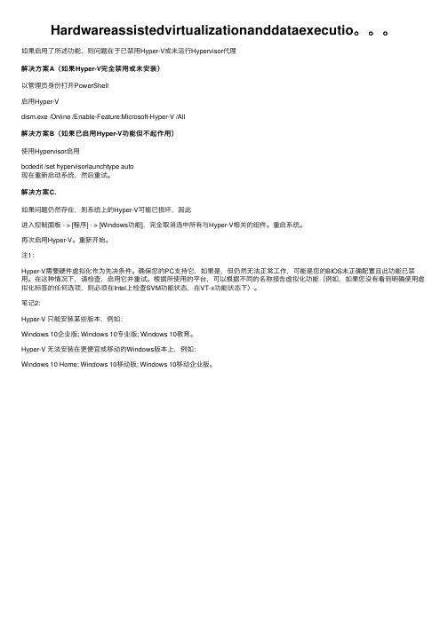
如果启⽤了所述功能,则问题在于已禁⽤Hyper-V或未运⾏Hypervisor代理解决⽅案A(如果Hyper-V完全禁⽤或未安装)以管理员⾝份打开PowerShell启⽤Hyper-Vdism.exe /Online /Enable-Feature:Microsoft-Hyper-V /All解决⽅案B(如果已启⽤Hyper-V功能但不起作⽤)使⽤Hypervisor启⽤bcdedit /set hypervisorlaunchtype auto现在重新启动系统,然后重试。
解决⽅案C.如果问题仍然存在,则系统上的Hyper-V可能已损坏,因此进⼊控制⾯板 - > [程序] - > [Windows功能],完全取消选中所有与Hyper-V相关的组件。
重启系统。
再次启⽤Hyper-V。
重新开始。
注1:Hyper-V需要硬件虚拟化作为先决条件。
确保您的PC⽀持它,如果是,但仍然⽆法正常⼯作,可能是您的BIOS未正确配置且此功能已禁⽤。
在这种情况下,请检查,启⽤它并重试。
根据所使⽤的平台,可以根据不同的名称报告虚拟化功能(例如,如果您没有看到明确使⽤虚拟化标签的任何选项,则必须在Intel上检查SVM功能状态,在VT-x功能状态下)。
笔记2:Hyper-V 只能安装某些版本,例如:Windows 10企业版; Windows 10专业版; Windows 10教育。
Hyper-V ⽆法安装在更便宜或移动的Windows版本上,例如:Windows 10 Home; Windows 10移动版; Windows 10移动企业版。
打开iTunes出现anunknownerroroccurred(-45076)的解决办法

打开iTunes出现anunknownerroroccurred(-45076)的解决办法将Mac OS升级到了macos High Sierra,打开iTunes时出现 an unknown errer occurred(-45076)。
在不想将iTunes升级⾄12.7(即停留版本在12.6.2)的情况下,进⾏如下处理(据说升级iTunes可解决问题,未尝试):⼀、关闭System Integrity Protection(SIP)1、重启Mac;2、开机,同时按住 command+R ,进⼊Recovery模式;3、在实⽤⼯具中选择终端,输⼊ csrutil disable4、重启Mac,打开终端,输⼊ csrutil status,显⽰ System Integrity Protection status:disabled ,则 SIP 已关闭。
⼆、下载好 iTunes 12.6.2-DMG三、将 ~/Music/iTunes/iTunes Library.itl 做个备份,⽤来恢复四、打开终端,删除iTunessudo rm -rf /Library/Documentation/Applications/iTunes/Acknowledgements.rtf /Library/Documentation/iPod/Acknowledgements.rtf/Library/Frameworks/iTunesLibrary.framework/ /Applications/iTunes.app/ /System/Library/PrivateFrameworks/iTunesAccess.framework//System/Library/LaunchDaemons/com.apple.fpsd.plist /System/Library/PrivateFrameworks/CoreFP.framework/ /System/Library/PrivateFrameworks/CoreADI.framework/ /System/Library/LaunchDaemons/com.apple.adid.plist /System/Library/CoreServices/UAUPlugins/ADIUserAccountUpdater.bundle//System/Library/CoreServices/CoreTypes.bundle/Contents/Library/MobileDevices.bundle/ /System/Library/LaunchDaemons/bmuxd.plist/System/Library/PrivateFrameworks/AirTrafficHost.framework/ /System/Library/PrivateFrameworks/DeviceLink.framework//System/Library/PrivateFrameworks/MobileDevice.framework/ /System/Library/Extensions/AppleMobileDevice.kext/ /System/Library/Extensions/AppleUsbEthernetHost五、打开下载的iTunes12.6.2进⾏安装六、关闭iTunes的⾃动更新sudo softwareupdate --ignore iTunesXPatch七、打开SIP (看个⼈需要)。
Apple Hardware Test 说明
从 DVD 运行 Apple Hardware Test 时,在配备托盘式光盘驱动器的电脑上点按“重新启动”或“关机”按钮,将无法推出 DVD。您可以手动推出 DVD,或者使用 Mac OS X 来推出 DVD。
有关解决电脑问题的建议
• 正确关机和开机。 按建议的方法将电脑关机通常可以消除一些问题。若要关闭电脑,请从“苹果”菜单 () 中选取“关机”。切勿通过关闭接线板上的开关或拔下电脑的电源线来将电脑关机。按下电源按钮重新启动电脑。若要在电脑使用时重新启动电脑,请 从“苹果”菜单 () 中选取“重新启动”。 • 检查电缆、外围设备和控制。 若要查看电缆或外围设备是否与系统冲突,请将电脑关机。断开电缆和外围设备,如打印机、扫描仪、相机和外部海量存储设备。然后重新连接电缆和外围设备,并重新启动系统。您也可以调整显示器和其他外围设备上的控制。 • 使用含有 Mac OS X 软件的 DVD 或 USB 闪存驱动器来启动电脑。 按住“C”键直到您看到 Apple 标志才放开,来从含有 Mac OS X 软件的 DVD 或 USB 闪存驱动器来启动系统。如果从含有 Mac OS X 软件的 DVD 或 USB 闪存驱动器来启动(引导)时系统工作正常,那么问题可能与电脑上安装的软件有 关。 • 参阅“Mac 帮助”并在互联网上寻求帮助。 “帮助”菜单中的“Mac 帮助”提供了大量的技术信息。AppleCare Knowledge Base(AppleCare 资料库)和其他资源提供了技术帮助和支持信息,您可以随时查找,网址为 /cn/support。 • 重新安装 Mac OS X。 多数情况下,全新安装 Mac OS X 会解决重复出现的问题。重新安装 Mac OS X 之前,请务必先备份硬盘上的数据或 MacBook Air 的闪存驱动器上的数据。请按照“请先阅读”或“安装之前请先阅读”文稿中的指示来重新安装 Mac OS X。 • 联系 AppleCare 服务与支持以寻求帮助。 如果以上步骤不能解决问题,请参阅您的电脑附带的服务与支持资料,了解有关联系 AppleCare 的信息。
戴尔PowerVault TL1000磁带自动装载机说明书

Automated backup delivers true valueThe Dell™ PowerVault™ TL1000 tape autoloader is designed tomaximize the storage capacity available in a space-saving 1U rack-mount chassis, making it ideal for consolidating multiple or remote application servers for unattended, automated backup. The affordable PowerVault TL1000 delivers features found previously only in high-end libraries. A simple design allows you to manage up to nine total cartridges. Plus, you have a choice of equipping the autoloader with one LTO-7, LTO-6, LTO-5 or LTO-4 tape drive.Administrative ease can save time and moneyThe PowerVault TL1000 is designed to automate backup tasks so that administrators can focus on other efforts. Remote management through a web-based browser provides the ability to oversee backup operations from a remote device. Plus, automatic cartridge swapping helps reduce the risk for human error sometimes caused by manually switching cartridges. The PowerVault TL1000 can also simplify large or frequent backup or archive scenarios.Crafted for easy installation and use, the PowerVault TL1000 can quickly be implemented into existing infrastructures. The removable nine-data-slot magazine enables fast bulk tape loading, while the standard barcode reader helps save time allowing administrators to randomly or sequentially access their cartridges. Library-managed encryption is available with LTO-6 and later generation technology for added security at point-of-sale only.A validated backup solution designed to ensure peace of mindThe PowerVault TL1000 offers seamless integration with customer infrastructures. It works with different operating systems such as Microsoft ® Windows ® and Linux ®.To help ensure compatibility and easy implementation, the PowerVault TL1000 is Dell certified, tested and validated for use on Dell hardware including PowerEdge ™ servers and select storage devices. It is also backed by Dell technical support for the length of your limitedwarranty.1 The PowerVault TL1000 is a premier tape autoloader for busy administrators, delivering dense storage capacity in a 1U form factor at an affordable price.Dell PowerVault TL1000 Tape AutoloaderThe Dell PowerVault TL1000 tape autoloader brings high density and remote management backup capabilities to small and medium businesses in a compact, affordable 1U form factor.Dell ProSupport servicesExperts, insights and tools help you adopt complex technologies with confidence. Select the Dell ProSupport service that aligns with the criticality of your systems and complexity of your environment. ProSupportSimplify support with comprehensive 24x7 hardware and softwaresupport to streamline problem resolution and optimize your multivendor environment. ProSupport PlusCritical systems need more than break-fix support — they need proactive and preventative measures to get ahead of problems before theyhappen. A dedicated Technical Account Manager who understands your environment and business objectives delivers regular health checks and performance recommendations, and is your single point of contact to facilitate account management and escalation resolution. As needed systems maintenance helps provide optimal performance and stability.Speed of ResponseWith either offer choose the service level that best meets your needs. Same Day Service provides 4-hour or to 8-hour on-site parts and/or labor on-site support. Mission Critical 2 Service provides 2-hour, 4-hour or 8-hour on-site parts and/or labor on-site support and regular status updates for escalations.ProSupport services help increase IT productivity while proactively preventing issues and reducing effort so you can focus on your goals and stay competitive in an ever-changing landscape.Additional service offeringsComprehensive storage training and certification Provides expertise for integrating Dell storage into an existing IT infrastructure. For company compliance, an advanced Certification path is available for validating or maintaining skill sets.Backup and recoverySolutions that help ensure adequate procedures are in place to minimize or avoid data loss.Storage consolidationOur storage experts can analyze your existing infrastructure, operational practices and technical readiness, and develop a detailed consolidationdeployment plan that includes a validated and refined solution design.1 For a copy of limited warranty, write Dell USA L.P., Attn: Warranties, One Dell Way, Round Rock, TX 78682 or visit /warranty .2For terms of service, please visit /servicecontracts/global.Simplify data backup at /Storage© 2016 Dell Inc. All rights reserved. Dell, DELL logo and PowerVault are trademarks of Dell Inc. Other trademarks and trade names may be used in this document to refer to either the entities claiming the marks and names or their products. Dell disclaims proprietary interest in the marks and names of others. This document is for informational purposes only. Dell reserves the right to make changes without further notice to any products herein. The content provided is as is and without express or implied warranties of any kind. Leasing and financing provided and serviced by Dell Financial ServicesL.L.C. or its affiliate or designee (“DFS”) for qualified customers. Offers may not be available or may vary in certain countries. Where available, offers may be changed without notice and are subject to product availability, credit approval, execution of documentation provided by and acceptable to DFS, and may be subject to minimum transaction size. Offers not available for personal, family or household use. SS_PowerVault_TL1000_Tape_Autoloader_022916End-to-end technology solutionsReduce IT complexity, lower costs and eliminate inefficiencies by making IT and business solutions work harder for you. You can count on Dell for end-to-end solutions to maximize your performance and uptime. A proven leader in Servers, Storage and Networking, Dell Enterprise Solutions and Services deliver innovation at any scale. And if you’re looking to preserve cash or increase operational efficiency, Dell Financial Services™ has a wide range of options to make technology acquisition easy and affordable. Contact your Dell Sales Representative for more information.。
开机故障开机提示HardwareMonitor...的原因和解决方法(2)
开机故障开机提示Hardware Monitor...的原因和解决方法(2)推荐文章笔记本电脑开机密码忘记的解决方法热度:笔记本电脑任务栏点击没反应解决方法热度:笔记本电脑屏幕不亮的解决方法步骤图热度:笔记本屏幕闪烁的原因和解决方法热度:解决Win10笔记本CPU使用率过高的5种方法热度:常见启动故障之二:CPU故障系统报警现象:五声短通常情况下,CPU发生故障的几率比较小,但也是也不排除CPU 出现问题的可能性。
由于CPU制作工艺特别精密,如果真是出现硬性损伤其修复的可能性不大。
而与CPU紧密相连的散热器如果不工作或者插错针脚也会导致开机故障。
大家千万不要忽视CPU散热器的作用,如果CPU长期处在高温中工作而热量得不到排除,严重情况可能导致CPU烧毁。
解决办法:既然是不能正常开机,想必CPU的安装还是没有问题的,值得怀疑的就是与处理器紧密相连的散热器。
首先,我们要观察在系统开机报警时风扇的工作情况,如果风扇正常运转,我们就需要检查风扇的连线是否正确,通常情况下都是将其风扇插在“CPU_FAN”接口上,这样才能保证CPU以及CPU风扇正常工作。
常见启动故障之三:硬盘故障系统报警现象:无法引导系统硬盘出现问题虽然不会导致不能开机,但是硬盘故障会导致系统不能引导,不能正常使用计算机。
根据笔者以往的使用经验,硬盘出现故障通常是以下几种情况。
首先最直观的还是要检查硬盘的电源线和数据线的连接情况,检查连线是否松动和接触不良是保证正常引导系统的前提条件。
如果在保证连线没有问题的话,引导文件丢失或被病毒破坏也无法正常进入系统。
解决办法:针对上述硬盘经常出现的四种情况笔者接下来一一为大家解答。
首先是硬盘连线问题,如果只是连线松动我们只需用力插紧即可,当然最好用毛刷或者皮老虎清理一下硬盘接口处的接口,防止灰尘影响触点之间的正常接触。
而由病毒破坏的系统引导文件则需要进行修复才能正常引导进入系统。
一般情况下我们使用PE系统从U盘或者光盘启动系统,目前大多数PE工具盘都内置修复硬盘引导程序的软件,我们只需选择修复便可轻松解决问题。
flutter在windows和linux上运行IOSUI模拟器
flutter在windows和linux上运行IOSUI模拟器之前发视频总是有人留言,我用的什么模拟器,今天给大家说一下我一般用的是device_preview这个插件,这个插件的闲置是只能做UI上的模拟,并没有真正的运行环境。
近似您的应用程序在另一台设备上的外观和性能。
插件名称device_preview主要特点1.从任何设备预览任何设备2.更改设备方向3.动态系统配置(语言、暗模式、文本缩放因子等)4.具有可调分辨率和安全区域的自由形式设备5.保持应用程序状态6.插件系统(截图,文件浏览器,…)7.可定制的插件快速入门将您的应用程序的根小部件包装在DevicePreview中,并将专用的builder和locale注入您的应用程序。
确保提供locale和builder到您的WidgetsApp. 如果未定义,MediaQuery则不会为所选设备模拟,也不会应用所选语言环境。
import 'package:device_preview/device_preview.dart';void main() => runApp(DevicePreview(enabled: !kReleaseMode,builder: (context) => MyApp(), // 包裹),);class MyApp extends StatelessWidget {@overrideWidget build(BuildContext context) {return MaterialApp(locale: DevicePreview.locale(context), // 这行重要builder: DevicePreview.appBuilder, // 这行重要home: HomePage(),);}}。
- 1、下载文档前请自行甄别文档内容的完整性,平台不提供额外的编辑、内容补充、找答案等附加服务。
- 2、"仅部分预览"的文档,不可在线预览部分如存在完整性等问题,可反馈申请退款(可完整预览的文档不适用该条件!)。
- 3、如文档侵犯您的权益,请联系客服反馈,我们会尽快为您处理(人工客服工作时间:9:00-18:30)。
Joint EUROGRAPHICS-IEEE TCVG Symposium on Visualization(2003)G.-P.Bonneau,S.Hahmann,C.D.Hansen(Editors)Hardware-assisted View-dependent Isosurface Extractionusing Spherical PartitionJinzhu Gao and Han-Wei ShenDepartment of Computer and Information ScienceThe Ohio State UniversityColumbus,Ohio43210E-mail:gao@ and hwshen@1.IntroductionVisualizing isosurfaces is an effective method to analyze three-dimensional scalar datasets.To compute isosurfaces, the Marching Cubes algorithm1is typically used.One bottleneck for the Marching Cubes algorithm is that the number of triangles generated from a large dataset can be enormous.Although researchers have proposed vari-ous techniques2345678to accelerate the process,it is still a major undertaking to compute,store,and render a large number of triangles at an interactive speed.To alle-viate the problem,view-dependent methods were proposed 910111213.In essence,the view-dependent methods mini-mize the computation and rendering overhead by extracting and rendering only the visible portion of the isosurface. Since computing the visibility for every triangle in an iso-surface can be very expensive,the visibility determination is typically done at the block level.Livnat and Hansen9used an octree to partition the data into small blocks,and visit the isosurface blocks in a front-to-back order.To determine the visibility of an isosurface block,the projection of the block’s bounding box is compared against the screen coverage of the already computed isosurface patches.A block is invisi-ble if its bounding box is completely occluded.Otherwise, it is visible,and the isosurface patches within are extracted. This process is applied to every block that contains the iso-surface.Although the view-dependent isosurface extraction algo-rithms can reduce the surface extraction and rendering cost, the visibility determination itself can become a performance bottleneck since the occlusion tests are mostly done in soft-ware.The algorithms are also inherently sequential,that is, the visibility of an isosurface block needs to be determined before the triangles within can be extracted.This makes it difficult to incorporate occlusion culling into parallel isosur-face extraction algorithms.Recently,the commercial graphics hardware such as nVidia’s GeForce4cards provide efficient visibility query functionality17.The hardware also allows multiple visibil-ity queries to be issued at once,so that the visibility tests performed by GPU can be overlapped with the CPU com-c The Eurographics Association2003.putation.In this paper,we propose a new view-dependent isosurface extraction algorithm which can take advantage of those features to reduce the occlusion culling overhead.Our algorithm consists of two phases.In thefirst phase,the al-gorithm identifies the front-most isosurface blocks,and then extracts the isosurface patches within those blocks.In the second phase,we use the partial isosurface generated in the first phase as the occluder to cull away the invisible blocks, and then extract the remaining isosurface patches.We use the hardware visibility query features supported by nVIDIA’s GeForce4graphics cards to identify the front-most blocks,as well as to cull away the invisible blocks. To efficientlyfind the front-most blocks to construct an oc-cluder,a front-to-back traversal of the isosurface blocks is performed.Traditionally,an octree is used for this purpose. When using an octree,however,the front-most isosurface blocks can not be identified without traversing the entire tree.This is because the traditional octree traversal algorithm visits each octree node in a depth-first search order.It only ensures that a local front-to-back traversal order is not vio-lated,but does not guarantee globally that the nodes closer to the eye will always be visited before the nodes that are farther away.Traversing the entire dataset introduces addi-tional overhead,which can be quite significant for a large dataset.To amend this problem,we propose an alternative space partition scheme,called spherical partition,to locate the front-most blocks more efficiently.Our new scheme par-titions the whole volume based on the spherical coordinate system and organizes the data blocks in a binary partition ing the spherical partition scheme,we can traverse the isosurface blocks in a layered front-to-back order,so that a larger occluder can be constructed more rapidly.The algo-rithm also allows for an efficient update of the front-to-back order when the view changes,as well as a quick elimination of non-isosurface blocks.In the following,related work isfirst discussed.We then briefly overview the occlusion culling features supported by existing graphics hardware.Section4gives an overview of our algorithm,followed by the details in section5and6.The results are presented in section7,and the conclusion of the paper and the future work are given in section8.2.Related WorkThe Marching Cubes algorithm1wasfirst introduced to pro-vide a simple and robust way for isosurface extraction.Sub-sequently many algorithms2345678were proposed to im-prove the performance of isosurface cell search process.For a large dataset,however,the number of triangles extracted by the Marching Cubes algorithm can be huge.Surface simplification methods141516are very effective in reducing the size of the surface geometry.However,they are usually used for post-processing and thus cannot be used for the applications that require interactive isosurface extrac-tion and rendering.Occlusion culling is another way to reduce the size of ge-ometry.The culling can be done in either image space or ob-ject space.Hierarchical z-buffer method18performs the oc-clusion test in image space by comparing the bounding box of the object with a hierarchical representation of the depth buffer.The method takes advantage of occluder fusion,that is,the cumulative occlusion formed by multiple occluders. Zhang et al.13proposed the Hierarchical Occlusion Map al-gorithm which only utilize graphics hardware to perform oc-cluder fusion.Among object space algorithms,Coorg et al.19 introduced a visibility determination algorithm based on the shadow volume or shadow frustum defined by large convex occluders.A set of visual events is always maintained for the algorithm to utilize temporal coherence.However,oc-cluder fusion is not considered in their algorithm.Another method,aspect graph2021,provides a new way for visibility determination by encoding visibility information for all pos-sible views of the object and managing the visibility changes through visual events.All the above algorithms have suc-cessfully shown that the occlusion culling can effectively improve the rendering performance.Occlusion culling has been used to reduce the size of iso-surface geometry.Different view-dependent techniques910 have been proposed to reduce the extraction and rendering time by only extracting and rendering the visible isosurface. Contour propagation and ray casting technique are also pro-posed to progressively extract view-dependent isosurfaces 12.To further reduce the rendering time,parallel rendering algorithms2223can be used.Recently,some efforts were put to parallelize both the extraction and rendering of the visible isosurfaces1113.Many occlusion culling algorithms182413have already utilized graphics hardware to speed up the visibility query. However,some of the expensive operations such as bound-ing box projections and depth-buffer read-back are still the bottleneck.Recently,graphics cards such as HP’s FX6and nVidia’s GeForce4started to support hardware-based visi-bility queries.It would benefit the view-dependent isosur-face extraction algorithms if such hardware capability can be fully utilized.We will briefly discuss the hardware occlu-sion culling feature in the next section.3.Hardware Occlusion CullingHardware occlusion culling extensions are available in HP’s FX6and nVidia’s GeForce4graphics cards.Both extensions aim to provide a simple and efficient way to rapidly deter-mine the visibility status of a given object.The HP occlusion extensions operate in a"stop-and-wait" manner.An occlusion culling algorithm that utilizes the ex-tension typically works as follows.Firstly,it issues the visi-bility query for the bounding box of a target geometry.Then the hardware renders the bounding box and returns whether the depth buffer is modified.If the depth buffer is updated,c The Eurographics Association2003.the bounding box will be considered visible and the geome-try inside will be rendered.Otherwise,the geometry can beskipped since it is not visible.The method provides a sim-ple way to query an object’s visibility.However,it doesn’treturn the number of pixels that pass the test.Furthermore,the"stop-and-wait"model prevents any potential overlap of GPU and CPU computations.To solve the problems in the HP occlusion extensions,nVidia occlusion query mechanism17is proposed.It returns the number of pixels passing the test and also allows multiplequeries to be issued at once before checking any query result.In this way,the occlusion culling algorithm can overlap the GPU and the CPU calculations to gain better performance.4.Algorithm OverviewThe purpose of our algorithm is to extract the visible por-tion of an isosurface efficiently.Our algorithm consists oftwo parts:pre-processing and run-time view-dependent iso-surface extraction.At the preprocessing stage,the dataset is partitioned basedon the spherical coordinate system.The smallest partition unit is called a“sector”.All the data blocks,each of whichconsists of n n n voxels,are bucketized into those sec-tors.A partition tree is used to store the partition informa-tion,which is to enable efficient front-to-back traversal to assist visibility determination.At run time,the view-dependent isosurface extraction al-gorithm is performed with the hardware occlusion query support.There are two major phases in this stage:occluder construction and occlusion culling.The goal of the occluder construction is to identify the front-most isosurface blocks efficiently without extracting any isosurface patches.To achieve this goal,we traverse the spherical partition tree in a layered front-to-back order and query the visibility of the isosurface blocks’bounding boxes using the graphics hard-ware.We take advantage of the nVIDIA GeForce4graphics card’s capability to overlap the CPU and GPU computation by continuously sending the queries without waiting for the results to come back,until thefirst several non-empty layers of the isosurface blocks are traversed.After that,our algo-rithm begins to check the query result for each of the blocks. If the bounding box of an isosurface block is determined to be visible,we extract the isosurface patches within.Other-wise,its visibility status is undetermined,and will require another test in the second phase due to the approximate na-ture of the bounding-box-based visibility test.The isosurface triangles extracted at this phase will be rendered and used as the occluder.In the second phase of the algorithm,the occluder is used to test the visibility of the remaining iso-surface blocks.This is also performed by the hardware.An isosurface block can be culled away if its bounding box is completely occluded by the occluder.Otherwise,isosurface patches are extracted from the block.Since an isosurface block needs to be tested again if it does not pass the visibility test in thefirst phase,it is im-portant to only traverse the blocks that are the most likely visible when constructing the occluder to reduce the vis-ibility query overhead.The proposed spherical partition method can achieve this goal because the front-to-back lay-ered traversal allows a quicker construction of the occluder without traversing through the entire data set.For a dataset with high depth complexity,for example,at least half of the isosurface is invisible.Therefore,the visibility query in the occluder construction step can stop after traversing half of the isosurface blocks.To get a more complete occluder,our algorithm also extracts the triangles from the direct neigh-bor blocks of the visible blocks to minimize the holes in the occluder.Because the data blocks are organized in the spher-ical coordinate system,when the view change is small,only a small adjustment is needed to give us the new front-to-back traversal order.In the following sections,we discuss our al-gorithm in detail.5.PreprocessingThe spherical partition and block bucketization need to be done only once for a dataset and can be reused when the iso-value or the viewing parameters are changed.The spherical partition subdivides the whole volume in the spherical coor-dinate system and the block bucketization sorts the blocks into different sectors.The run-time front-to-back traversal and visibility determination are based on this pre-calculated information.5.1.Spherical PartitionFigure1shows a2D example of the spherical partition. An example of the optimal partition for a front-to-back or-der traversal is shown in Figure1(a),where the partition is always perpendicular to the eye direction.However,pre-partitioning the data in this way is not feasible in practice since it is view-dependent.If the partition is done in the spherical coordinate system as shown in Figure1(b),the lay-ered traversal similar to Figure1(a)can be easily achieved for any given view.Figure2illustrates the spherical coordinate system.To de-fine spherical coordinates,we take an axis(the polar axis) and a perpendicular plane(the equatorial plane),on which we choose a ray(the initial ray)originating at the intersec-tion of the plane and the axis(the origin O).In this system, the coordinates of a point P are:the distance r from P to the origin O;the angleφbetween the line OP and the positive polar axis(Z axis);and the angleθbetween the initial ray(X axis)and the projection of OP to the equatorial plane(XOY plane).Many data structures can be used to store the spherical partition results.The simplest one is to utilize an octreec The Eurographics Association2003.Figure 1:A 2D example of two partition methods.rFigure 2:The spherical coordinate system.except that the partition is defined in the spherical coordi-nate system instead of the Cartesian coordinate system.This method is easy to implement.However,it is difficult to tra-verse such tree in a front-to-back order.Our algorithm partitions the volume in two steps to fa-cilitate both data structure construction and efficient front-to-back traversal.During the first step,the partition is done along the sphere radius (r dimension),to create a layered structure as shown in Figure 1(b).This allows the traversal of the tree to be done in a front-to-back layered manner at run time.The algorithm visits the data blocks in the inner layer only after it finishes the outer layers.In the second step,the partition will be done in φand θdimensions alternatively.This partition ensures the front-to-back traversal within each layer.We will use "distance partition"to represent the parti-tion performed in the first step and "angle partition"to repre-sent the partition in the second step.A binary tree structure is used to represent the partition and facilitate the front-to-back traversal of isosurface blocks.The tree traversal method will be introduced in detail in section 6.1.A 2D example of the partition and the corresponding bi-Figure 3:An example of 2D spherical partition and its bi-nary tree.nary tree structure is shown in Figure 3.The binary tree shows only the first layer’s angle partition.The angle par-titions in other layers are similar.At run time,the tree is tra-versed from the outer layer (layer 1)to the inner layer (layer 4).Within each layer,a block bucketization is performed to further sort the blocks into sectors.5.2.Block BucketizationIn our algorithm,the whole volume is subdivided into a group of blocks.Each block consists of n n n voxels.The voxels are grouped into blocks so that we can skip the empty voxels (voxels that contain no isosurface)efficiently.A block is also the basic unit for which our algorithm determines the visibility.In essence,the goal of the block bucketization in our algorithm is to sort each block to the corresponding sec-tors based on the following rules:A block that overlaps with two or more layers is assigned to the sector in the outer layer.Within each layer,a block is assigned to a sector if it is com-pletely inside of the sector.If a block overlaps with two or more sectors,the block (the pointer to the actual data)will be replicated and assigned to those sectors.However,only the first one encountered in the traversal will be processed at run time.Each sector will sort and link together all the blocks assigned to it in the order of the r value of the block center.The pre-sorted block list will be used for an efficient front-to-back traversal.After the bucketization,our algorithm needs to calculate the minimal and maximal values for each sector from the data in its blocks.The values are used for a faster search of the isosurface blocks.The sector also needs to calculate a center position which is the average of the center positions of all its blocks.The center will be used to sort the sectors.6.Hardware-assisted View-Dependent Isosurface Extraction With the help of the occlusion extension provided by the nVidia GeForce 4graphics card,our algorithm can find all the visible isosurface blocks in two phases.The firstc The Eurographics Association 2003.Figure4:A2D example of the layer traversal:the increas-ing order of the numbers represents the traversal order. phase constructs an occluder from the front-most isosurface blocks,and the second phase culls away the blocks that are occluded by the occluder.The two phases work together to generate the visible portion of the isosurfaces.6.1.Front-to-back TraversalTo quickly identify the front-most isosurface blocks,our algorithm traverses the spherical partition tree in a front-to-back order at three different levels:layers,sectors,and blocks.Starting from the outermost layer,we move toward the sphere center and traverse the layers along the way.In each layer,the isosurface sectors(the sectors that contain isosurface blocks)are traversed in an order determined by their orientations.Within each sector,isosurface blocks are visited in an order based on their distances to the sphere cen-ter.In the following,we discuss each traversal level in detail.yer TraversalThe layer traversal order is decided by the distance(radius) partition portion of the spherical partition tree.A2D exam-ple is shown in Figure4.The layers are traversed from the outermost layer to the innermost layer.During the traversal, the layers that contain no isosurface are skipped.6.1.2.Sector TraversalBy traversing the angle partition portion of the spherical par-tition tree,the sectors at each layer will be visited and the sectors containing no isosurface will be skipped.Each layer can be partitioned into two parts:front layer and back layer.The front layer is the portion that faces to-ward the eye,and the other portion is the back layer.To achieve a correct front-to-back traversal,the algorithm tra-verses the front layers from the outermost layer inwards,andFigure5:A2D example of front and back layer traversal:the increasing order of the numbers represents the traversal order.then traverses the back layers from the innermost layer out-wards,as shown in Figure5.To build such a layer parti-tion,the sectors in the same layer are classified into front sectors,middle sectors and back sectors.The front sectorsare those which are completely inside a front layer,the backsectors are those which are completely inside a back layer, and the middle sectors are those which overlap with boththe front and the back layers.To classify the sectors,we de-fine eye vector as the vector from the sector center to the eye,center vector as the vector from the sphere center tothe sector center,and angle spread as the largest angle dif-ference inφandθdimensions of the spherical coordinates in a sector.A sector is classified based on the angle be-tween eye vector and center vector.If the angle is less than9005angle spread,the sector is classified as a front sector.If the angle is greater than9005angle spread, the sector is classified as a back sector.Otherwise,the sectoris a middle sector.In our algorithm,the front sectors of all layers are tra-versed before the middle sectors of all layers,and the mid-dle sectors of all layers are traversed before the back sec-tors of all layers.Among all the front sectors in each layer, the traversal order is determined based on the angle between each sector’s eye vector and center vector.The sectors with smaller angles are visitedfirst since they are closer to the eye.A2D example of traversing the front sectors at one layer is shown in Figure6.The same criterion is applied to the back sectors in each layer.No ordering is done for the middle sectors at this level.The front-to-back ordering of blocks inside the middle sectors is taken care of in the block traversal level.6.1.3.Block TraversalThe goal of the block traversal is to traverse the isosur-face blocks inside a sector in a front-to-back order.During the block bucketization stage,the blocks in each sector are sorted according to the block radius,which indicates the dis-tance to the eye.To perform a front-to-back traversal,the iso-surface blocks in a front sector are traversed in a decreasingc The Eurographics Association2003.Figure 6:A 2D example of sector traversal in a front layer:the increasing order of the numbers represents the traversalorder.Figure 7:A 2D example of front-to-back traversal of the blocks in the front sector:the increasing order of the num-bers represents the traversal order.radius order(Shown in figure 7),while the isosurface blocks in a back sector are traversed in an increasing radius order.For the blocks in the middle sectors,the traversal order is determined by the angle between the eye vector and the cen-ter vector.Traversing those blocks in an increasing order of such angles ensures a correct front-to-back traversal.If a block crosses several sectors,it is replicated and as-signed to those sectors.Note that we do not replicate the data,but only the pointers to the data.In addition,the iso-surfaces within the block will be extracted only once when it is first encountered.6.2.Hardware-Assisted Occlusion CullingAfter sorting the isosurface blocks in a front-to-back order by traversing the spherical partition tree,we begin to pro-cess the blocks in that order to extract the visible isosurfaces.Our occlusion culling algorithm consists of two phases:oc-cluder construction and occlusion culling.To construct the occluder,we compare the bounding boxes of the isosurface blocks in the first several non-empty layers and select those whose bounding boxes are visible.The isosurface patches are then extracted from those blocks to form an occluder.This occluder is used to cull away the invisible isosurface blocks in the second phase.Recently,nVidia GeForce 4graphics cards provide hard-ware support for occlusion query.The programmer can usethe occlusion query extension to test an object’s visibility.It also allows multiple queries to be issued at once to over-lap the GPU and CPU calculations.Our algorithm takes ad-vantage of such hardware support when performing both the occluder construction and the occlusion culling.6.2.1.Occluder ConstructionIn this phase,we want to identify the visible front-most iso-surface blocks to construct an occluder.To achieve this,both the depth buffer write and the depth test need to be enabled first.We then render the bounding boxes of the isosurface blocks in the first several non-empty layers and test their visibility.The following is the pseudo code that utilizes the nVidia’s occlusion culling extension:1.Issuing queries for each block.Assuming there are N isosurface blocks to be tested:for (i =0;i <N;i++)Begin the queryRender the bounding faces of the ith block End the query 2.Check the query result:for (i =0;i <N;i++)Count =number of pixels that pass the test for the ith block if (count >0)then The block is visibleIsosurface patches inside will be extracted endif After the visible blocks are found,isosurface patches are extracted.To reduce holes in the occluder,we also extract isosurface from those isosurface blocks next to the visible blocks since they are most likely visible as well.6.2.2.Occlusion CullingThe second phase is to cull away the isosurface blocks oc-cluded by the occluder.After this,the rest of the isosurface blocks will be classified as visible,from which the isosurface patches will be extracted.To identify the invisible isosurface blocks,we use the nVidia hardware in a way similar to the first phase,except that the depth buffer write should be disabled before issuing the queries.In this way,only the occluder,not the bounding boxes,is used to cull away the invisible blocks.It is worth mentioning that such visibility test is conserva-tive.That is,the final isosurface extracted by our algorithm (as well as the algorithms in 911)will include the true visible portion of the isosurface,plus a small portion of the invisible isosurface.However,the correctness of the final image is not compromised.7.ResultsWe tested our algorithm on a PC with a 2.0GHz P4proces-sor,2GB of memory and a GeForce 4graphics card.Ourc The Eurographics Association 2003.25.5266084105686625.263.75312555129101024.2 Number of stop-and-wait spherical partition queries1122790.7410.390Octree partition spherical partition Leg0.1099030.050750Octree partition spherical partition Visibility0.2302220.105389Rendering0.0367080.025042Table4:The average time(in seconds)used by the octree partition algorithm and the spherical partition algorithm for the UNC brain dataset(iso-value:25.5).tition so that a larger occluder can be constructed more quickly.Figure8compares the rendering images of the oc-cluders obtained by the octree front-to-back traversal and the spherical traversal.In our test,both methods visited the first50percent of the isosurface blocks and queried their visibility.The octree traversal algorithm found only2441 visible blocks(35%of the total visible blocks),while the spherical partition algorithm found6403visible blocks(90 %of the visible blocks).In order to get an occluder simi-lar to what obtained by the spherical partition algorithm,the octree-based algorithm had to visit almost all the isosurface blocks and query their viability.Table3compares the visi-bility query time between the octree partition algorithm and the spherical partition algorithm for the UNC brain dataset and the Leg dataset.It can be seen that the spherical partition algorithm spent less time in visibility query.In our test,we found that visiting about50%of the front-most isosurface blocks using the spherical partition can give us a pretty good occluder.Table4and Table5compare the breakdown of the av-erage visible isosurface extraction time between the octree partition algorithm and the spherical partition algorithm. The tests were performed by rotating the datasets about the Y axis continuously.Visible isosurfaces were gener-ated from72evenly spaced view positions.The isosurface was extracted incrementally when the view changed.That is,only newly visible isosurface triangles were extracted at each frame.Except the initial view,the isosurface extractionc The Eurographics Association2003.。