HLMP-C217-O0001中文资料
паркер汉尼夫公司水力系列产品目录说明书

ABV101............Accumulator Bleed-Down Valve......................MV15-MV17 CDP161............Double P.O. Check Valves..................................LH85-LH86 CDPH103..........Double P.O. Check Valves..................................LH83-LH84 CP044P............Single P.O. Check Valves...................................LH46-LH48 CP074P............Single P.O. Check Valves...................................LH49-LH51 CP084P............Single P.O. Check Valves...................................LH52-LH54 CPC101P..........Pilot-to-Close Check Valves...............................LH64-LH66 CPC161P..........Pilot-to-Close Check Valves...............................LH67-LH69 CPD084P..........Double P.O. Check Valves..................................LH80-LH82 CPH064P..........Single P.O. Check Valves...................................LH55-LH57 CPH104P..........Single P.O. Check Valves...................................LH58-LH60 CPH124P..........Single P.O. Check Valves...................................LH61-LH63 CS041B............Shuttle Valves....................................................LH87-LH89 CSH101B..........Shuttle Valves....................................................LH90-LH92 CSP161............Single P.O. Check Valves...................................LH78-LH79 CSPH103..........Single P.O. Check Valves...................................LH76-LH77 CV041P............Check Valves.........................................................LH1-LH3 CV081P &091P.................Check Valves.........................................................LH4-LH6 CV082P............Check Valves.........................................................LH7-LH9 CV101P............Check Valves.....................................................LH10-LH12 CV102P............Check Valves.....................................................LH13-LH15 CV103P............Check Valves.....................................................LH16-LH18 CVH061P..........Check Valves.....................................................LH25-LH27 CVH071P..........Check Valves.....................................................LH28-LH30 CVH081P &091P.................Check Valves.....................................................LH31-LH33 CVH103P..........Check Valves.....................................................LH34-LH36 CVH084P..........Check Valves.....................................................LH37-LH39 CVH104P..........Check Valves.....................................................LH40-LH42 CVH121P..........Check Valves.....................................................LH43-LH45 CVH161P..........Check Valves.....................................................LH19-LH21 CVH201P..........Check Valves.....................................................LH22-LH24 CVO101P..........Vent-to-Open Check Valves...............................LH70-LH72 CVO161P..........Vent-to-Open Check Valves...............................LH73-LH75 DF083...............Sol. Operated, P.C. Proportional Flow Cont...........PV1-PV4 DF092C............Sol. Operated, P.C. Proportional Flow Cont...........PV5-PV8 DF092N............Sol. Operated, P.C. Proportional Flow Cont.........PV9-PV12 DF102C............Sol. Operated, P.C. Proportional Flow Cont.......PV13-PV16 DF102N............Sol. Operated, P.C. Proportional Flow Cont.......PV17-PV20 DF102P............Sol. Operated, P.C. Proportional Flow Cont.......PV21-PV23 DF122...............Sol. Operated, P.C. Proportional Flow Cont.......PV24-PV27 DF161C............Solenoid Operated, Throttle Valves....................PV28-PV31 DF201C............Solenoid Operated, Throttle Valves....................PV32-PV35 DH082..............Pilot Operated, 2-Way Valves............................DC22-DC24 DH103..............Pilot Operated, Directional Valves......................DC25-DC28 DL081..............Manual, Poppet-Type, 2-Way Valves.....................DC1-DC3 DL101..............Manual, Poppet-Type, 2-Way Valves.....................DC4-DC6 DL102..............Manual, Spool-Type, 2-Way Valves.......................DC7-DC9 DL103..............Manual, Spool-Type, 3-Way Valves...................DC10-DC12 DL104..............Manual, Spool-Type, 4-Way Valves...................DC13-DC15 DM103.............Manual, Rotary, 3-Way Valves...........................DC16-DC18 DM104.............Manual, Rotary, 4-Way Valves...........................DC19-DC21 DPR083B..........Sol. Operated, Proportional Pres. Reducing......PV36-PV39 DPR083C..........Sol. Operated, Proportional Pres. Reducing......PV40-PV43 DPR083C30......Sol. Operated, Proportional Pres. Reducing......PV44-PV47 DPR083N.........Sol. Operated, Proportional Pres. Reducing......PV48-PV51 DPR103C..........Sol. Operated, Proportional Pres. Reducing......PV52-PV55DPR104C10......Sol. Operated, Proportional Pres. Reducing......PV56-PV59 DS085..............Solenoid, Spool-Type, 4-Way, 3-Pos.............DC127-DC130 DS086C6Mand 096............Sol., Bi-Directional, Poppet-Type, 2-Way.......DC148-DC151 DS105..............Solenoid, Spool-Type, 4-Way, 3-Pos.............DC131-DC134 DS161..............Solenoid, Poppet-Type, 2-Way Valves...............DC56-DC59 DS162..............Solenoid, Spool-Type, 2-Way Valves.................DC84-DC87 DS123B............Solenoid, Spool-Type, 3-Way Valves.............DC104-DC106 DS163..............Solenoid, Spool-Type, 3-Way Valves.............DC107-DC110 DS201..............Solenoid, Poppet-Type, 2-Way Valves...............DC60-DC63 DS083BP3........Solenoid, Poppet-Type, 3-Way Valves...............DC64-DC67 DSH08D1C.......Solenoid, Poppet-Type, 2-Way Valves...........DC139-DC141 DSH08D6C.......Solenoid, Poppet-Type, 2-Way Valves...........DC145-DC147 DSH081 & 091.Solenoid, Poppet-Type, 2-Way Valves...............DC36-DC39 DSH082 & 092.Solenoid, Spool-Type, 2-Way Valves.................DC72-DC75 DSH083............Solenoid, Spool-Type, 3-Way Valves.................DC92-DC95 DSH084............Solenoid, Spool-Type, 4-Way Valves.............DC115-DC118 DSH085............Solenoid, Spool-Type, 4-Way, 3-Pos.............DC135-DC138 DSH101............Solenoid, Poppet-Type, 2-Way Valves...............DC44-DC47 DSH102............Solenoid, Spool-Type, 2-Way Valves.................DC80-DC83 DSH103............Solenoid, Spool-Type, 3-Way Valves.............DC100-DC103 DSH104............Solenoid, Spool-Type, 4-Way Valves.............DC123-DC126 DSH106C6........Sol., Bi-Directional, Poppet-Type, 2-Way.......DC156-DC159 DSH121............Solenoid, Poppet-Type, 2-Way Valves...............DC52-DC55 DSL08D6C........Sol., Bi-Directional, Poppet-Type, 2-Way.......DC142-DC144 DSL080DC........Soft Seat, Direct Act., Poppet-Type, 2-Way.......DC29-DC31 DSL081 & 091.Solenoid, Poppet-Type, 2-Way Valves...............DC32-DC35 DSL082 & 092.Solenoid, Spool-Type, 2-Way Valves.................DC68-DC71 DSL083............Solenoid, Spool-Type, 3-Way Valves.................DC88-DC91 DSL084............Solenoid, Spool-Type, 4-Way Valves.............DC111-DC114 DSL101............Solenoid, Poppet-Type, 2-Way Valves...............DC40-DC43 DSL102............Solenoid, Spool-Type, 2-Way Valves.................DC76-DC79 DSL103............Solenoid, Spool-Type, 3-Way Valves.................DC96-DC99 DSL104............Solenoid, Spool-Type, 4-Way Valves.............DC119-DC122 DSL106C6........Sol., Bi-Directional, Poppet-Type, 2-Way.......DC152-DC155 DSL121............Solenoid, Poppet-Type, 2-Way Valves...............DC48-DC51 EHVC................Electrohydraulic Valve Controller.......................PV92-PV99 ERV091C..........Solenoid Operated, Proportional P.C.................PV60-PV63 ERV091N..........Solenoid Operated, Proportional P.C.................PV64-PV67 ERV092N..........Solenoid Operated, Proportional P.C.................PV68-PV71 ERV101C..........Solenoid Operated, Proportional P.C.................PV72-PV75 ERV101N..........Solenoid Operated, Proportional P.C.................PV76-PV79 ERV102N..........Solenoid Operated, Proportional P.C.................PV80-PV83 ERV121N..........Solenoid Operated, Proportional P.C.................PV84-PV87 ERV161N..........Solenoid Operated, Proportional P.C.................PV88-PV91 FA101...............Pressure Compensated Flow Control................VC16-VC18 FC101...............Pressure Compensated Flow Control................VC22-VC24 FCP101.............Priority-Type, P.C. Valves...................................VC38-VC40 FCPH121..........Priority-Type, P.C. Valves...................................VC41-VC43 FCR101............Restrictive-Type, P.C. Valves..............................VC29-VC31 FCR121............Restrictive-Type, P.C. Valves..............................VC32-VC34 FCR161............Restrictive-Type, P.C. Valves..............................VC35-VC37 FDC101............Flow Divider/Combiner Valves...........................VC19-VC21 FL101...............Filter Cartridge.....................................................MV7-MV9 FP101...............Priority-Type, P.C. Flow Control Valves..............VC47-VC50 FPR101............Priority-Type, P.C. Flow Control Valves..............VC51-VC53 FR101...............Restrictive-Type, P.C. Flow Control Valves.........VC44-VC46FV101 & 102 .... Flow Control Valves ........................................... VC25-VC28 HLSVH101........Hi-Lo Unloading Valve.....................................MV10-MV12 HP101..............Hand Pump.....................................................MV13-MV14 NV102..............Needle Valves........................................................VC7-VC9 NV161..............Needle Valves....................................................VC10-VC12 NV162..............Needle Valves....................................................VC13-VC15 NVH081............Needle Valves........................................................VC1-VC3 NVH101............Needle Valves........................................................VC4-VC6 Offer of Sale............................................................................................TI15 P10-2*.............Cavity Plugs................................................................MV19 PDS101............Pressure Sensing..............................................PC67-PC69 PDS161............Pressure Sensing..............................................PC70-PC72 PMK101...........Panel Mount Kit..........................................................MV18 PN 812724.......Block Off Plate............................................................MV20 PR103..............Pressure Reducing/Relieving Valves.................PC91-PC93 PRCH101..........Pressure Reducing/Relieving Valves With.........................PC79-PC81PRH081............P.O. Pressure Reducing/Relieving Valves..........PC73-PC75 PRH082............P.O. Pressure Reducing Valves..........................PC94-PC96 PRH101............P.O. Pressure Reducing/Relieving Valves..........PC76-PC78 PRH102............P.O. Pressure Reducing Valves..........................PC97-PC99 PRH121............P.O. Pressure Reducing/Relieving Valves..........PC82-PC84 PRH121V..........P.O. Pressure Reducing/Relieving Valves..........PC85-PC87 PRH122............P.O. Pressure Reducing Valves......................PC100-PC102 PRH161............P.O. Pressure Reducing/Relieving Valves..........PC88-PC90 PRH162............P.O. Pressure Reducing Valves......................PC103-PC105PRS102............Pressure Reducing Spool Valves...................PC106-PC108PRS162............Pressure Reducing Spool Valves...................PC109-PC111 RAH081 & 091.P.O. Relief Valves...............................................PC49-PC51 RAH101............P.O. Relief Valves...............................................PC52-PC54 RAH101V..........P.O. Ventable Relief Valves................................PC55-PC57 RAH121............P.O. Relief Valves...............................................PC58-PC60 RAH161............P.O. Relief Valves...............................................PC61-PC63 RAH201............P.O. Relief Valves...............................................PC64-PC66 RASPH21.........Subplate/Relief Valve...........................................MV1-MV3 RASPH31.........Subplate/Relief Valve...........................................MV4-MV6 RD042..............Direct Acting Relief Valves.....................................PC7-PC9 RD072..............Direct Acting Relief Valves.................................PC13-PC15 RD102..............Direct Acting Relief Valves.................................PC19-PC21 RD163..............Direct Acting Relief Valves.................................PC31-PC33 RDH062............Direct Acting Relief Valves.................................PC10-PC12 RDH081............Direct Acting Relief Valves.....................................PC1-PC3 RDH082............Direct Acting Relief Valves.................................PC16-PC18 RDH083............Direct Acting Relief Valves.................................PC22-PC24 RDH101............Direct Acting Relief Valves.....................................PC4-PC6 RDH103............Direct Acting Relief Valves.................................PC25-PC27 RDH104............Differential Relief Valves With..........................................PC34-PC36 RDCH103.........Direct Acting Relief Valves With..........................................PC28-PC30PC139-PC141 SVCH101..........Sequence Valves w/Free Rev. Flow Check.....PC118-PC120 SVH081............Sequence Valves............................................PC112-PC114 SVH082............P.O. Sequence Valves....................................PC127-PC129 SVH101............Sequence Valves............................................PC115-PC117 SVH102............P.O. Sequence Valves....................................PC130-PC132 SVH121............Sequence Valves............................................PC121-PC12308 & 09............Coils 1/2″ I.D..........................................................CL1-CL2 DF102P &DPR104C10......Coils 1/2″ I.D..........................................................CL3-CL4 10, 12,16 & 20............Coils 5/8″ I.D..........................................................CL5-CL6 12 & 16............Coils 1″ I.D.............................................................CL7-CL8 08 & 09............Unicoils 1/2″ I.D...................................................CL9-CL10 10 & 12............Unicoils 5/8″ I.D.................................................CL11-CL12 08 & 09............Waterproof Coils 1/2″ I.D............................................CL13 10 & 12............Waterproof Coils 5/8″ I.D............................................CL14 Installation Data.........................................................................................TI1 04.....................Two and Three Way Cavity Details..................................TI206.....................Two and Three Way Cavity Details..................................TI307.....................Two and Three Way Cavity Details..................................TI408.....................Two, Three and Four Way Cavity Details...................TI5-TI609.....................Two Way Cavity Detail....................................................TI710.....................Two, Three and Four Way Cavity Details...................TI8-TI9 12.....................Two, Three and Four Way Cavity Details...............TI10-TI11 16.....................Two, Three and Four Way Cavity Details...............TI12-TI13 20.....................Two Way Cavity Detail..................................................TI14 B04-2**...........Single Function, Two Step Bodies.........................VB1-VB2 B04-3**...........Single Function, Three Step Bodies.......................VB3-VB4 B06-2**...........Single Function, Two Step Bodies.........................VB5-VB6 B06-3**...........Single Function, Three Step Bodies.......................VB7-VB8 B07-2**...........Single Function, Two Step Bodies.......................VB9-VB10 B07-3**...........Single Function, Three Step Bodies...................VB11-VB12 B08-2**...........Single Function, Two Step Bodies.....................VB13-VB14 B08-3**...........Single Function, Three Step Bodies...................VB15-VB16 B08-4**...........Single Function, Four Step Bodies.....................VB17-VB18 B09-2**...........Single Function, Two Step Bodies.....................VB19-VB20 B10-2**...........Single Function, Two Step Bodies.....................VB21-VB22 B10-2T**.........Single Function, Two Step Bodies.....................VB23-VB24 B10-3**...........Single Function, Three Step Bodies...................VB25-VB26 B10-3L**.........Single Function, Three Step Bodies...................VB27-VB28 B10-4**...........Single Function, Four Step Bodies.....................VB29-VB30 B12-2**...........Single Function, Two Step Bodies.....................VB31-VB32 B12-3**...........Single Function, Three Step Bodies...................VB33-VB34 B12-4**...........Single Function, Four Step Bodies.....................VB35-VB36 B16-2**...........Single Function, Two Step Bodies.....................VB37-VB38 B16-3**...........Single Function, Three Step Bodies...................VB39-VB40 B16-3S**.........Single Function, Three Step Bodies...................VB41-VB42 B20-2**...........Single Function, Two Step Bodies.....................VB43-VB44 Single Function BodiesCavity DetailsCartridge Valve CoilsSVH122............P.O. Sequence Valves....................................PC133-PC135 SVH161............Sequence Valves............................................PC124-PC126 SVH162............P.O. Sequence Valves....................................PC136-PC138 TR081..............Thermal Relief Valves....................................PC142-PC144 VF101...............Velocity Fuses....................................................VC54-VC56 XR101..............Cross-Over Relief Valves...................................PC37-PC39 XRDH101.........Cross-Over Relief Valves...................................PC40-PC42 XRDH102.........Dual Relief Valves w/Anti-Cavitation Checks......PC43-PC45 XRDH103.........Cross-Over Relief Valves...................................PC46-PC48。
HLMP-1790C0001中文资料
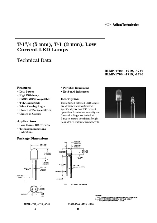
HLMP-7000, -7019, -7040Package DimensionsA BHLMP-1700, -1719, -1790HLMP-4700, -4719, -4740Note:1. θ1/2 is the typical off-axis angle at which the luminous intensity is half the axial luminous intensity.Part Numbering SystemHLMP-X7XX - X X X XXMechanical Option00: Bulk01: Tape & Reel, Crimped Leads02, BH: Tape & Reel, Straight LeadsA1, B1: Right Angle Housing, Uneven LeadsA2, B2: Right Angle Housing, Even LeadsFH: 2 Iv bins select with Inventory ControlColor Bin Options0: Full color bin distributionB: Color bins 2 & 3 onlyMaximum Iv Bin Options0: Open (No. max. limit)Others: Please refer to the Iv bin TableMinimum Iv Bin OptionsPlease refer to the Iv Bin TableColor Option00: GaP HER19: GaP Yellow40: GaP Green90: GaP GreenPackage Options4: T-13/4 (5 mm)1: T-1 (3 mm)Electrical/Optical Characteristics at T A = 25°CTest Symbol Description T-13/4T-1Min.Typ.Max.Units Conditions V F Forward Voltage47001700 1.7 2.0V 2 mA47191719 1.8 2.547401790 1.9 2.2V R Reverse Breakdown47001700 5.0V I R = 50 µA Voltage47191719 5.047401790 5.0λd Dominant47001700626nm Note 1 Wavelength4719171958547401790569∆λ1/2Spectral Line4700170040nmHalfwidth47191719364740179028τS Speed of Response4700170090ns471917199047401790500C Capacitance4700170011pF V F = 0,4719171915 f = 1 MHz4740179018RθJ-PIN Thermal47001700260[3]°C/W Junction to Resistance47191719290[4]Cathode Lead47401790λPEAK Peak Wavelength47001700635nm Measurement47191719583at peak47401790565ηV Luminous Efficacy47001700145lumens Note 247191719500watt47401790595Notes:1. The dominant wavelength, λd, is derived from the CIE chromaticity diagram and represents the single wavelength which defines thecolor of the device.2. The radiant intensity, I e, in watts per steradian, may be found from the equation I e = I V/ηV, where I V is the luminous intensity incandelas and ηV is luminous efficacy in lumens/watt.3. T-13/4.4. T-1.ParameterMaximum RatingUnits Power DissipationRed 24mW(Derate linearly from 92°C at 1.0 mA/°C)Yellow 36Green24DC and Peak Forward Current7mA Transient Forward Current (10 µs Pulse)[1]500mA Reverse Voltage (I R= 50 µA) 5.0VOperating Temperature Range Red/Yellow -55°C to 100°C Green-20°C to 100°CStorage Temperature Range -55°C to +100°C Lead Soldering Temperature 260°C for 5 seconds[1.6 mm (0.063 in.) from body]Note:1. The transient peak current is the maximum non-recurring peak current the devices can withstand without damaging the LED die and wire bonds. It is not recommended that the device be operated at peak currents beyond the Absolute Maximum Peak Forward Current.Figure 2. Forward Current vs. Forward Voltage.Figure 3. Relative Luminous Intensity vs. Forward Current.VOLTAGE – V624810Maximum tolerance for each bin limit is ±18%.Maximum tolerance for each bin limit is ±18%.Maximum tolerance for each bin limit is ±18%.Tolerance for each bin limit is ±0.5 nm.Mechanical Option MatrixMechanical Option Code Definition00Bulk Packaging, minimum increment 500 pcs/bag01Tape & Reel, crimped leads, min. increment 1300 pcs/bag for T-1 3/4, 1800pcs/bag for T-102Tape & Reel, straight leads, min. increment 1300 pcs/bag for T-1 3/4, 1800pcs/bag for T-1A1T-1, Right Angle Housing, uneven leads, minimum increment 500 pcs/bagA2T-1, Right Angle Housing, even leads, minimum increment 500 pcs/bagB1T-1 3/4, Right Angle Housing, uneven leads, minimum increment 500 pcs/bagB2T-1 3/4, Right Angle Housing, even leads, minimum increment 500 pcs/bagBH T-1, Tape & Reel, straight leads, minimum increment 2000 pcs/bagFH Devices that require inventory control and 2 I v bin selectR1Tape & Reel, crimped leads, reeled counter clockwise, cathode lead leavingthe reel firstNote:All categories are established for classification of products. Products may not be available in all categories. Please contact your local Agilent representative for further clarification/information./semiconductors For product information and a complete list of distributors, please go to our web site.For technical assistance call:Americas/Canada: +1 (800) 235-0312 or (916) 788-6763Europe: +49 (0) 6441 92460China: 10800 650 0017Hong Kong: (+65) 6756 2394India, Australia, New Zealand: (+65) 6755 1939 Japan: (+81 3) 3335-8152(Domestic/Interna-tional), or 0120-61-1280(Domestic Only) Korea: (+65) 6755 1989Singapore, Malaysia, Vietnam, Thailand, Philippines, Indonesia: (+65) 6755 2044 Taiwan: (+65) 6755 1843Data subject to change.Copyright © 2003 Agilent Technologies, Inc. September 10, 20035988-8054EN。
AM217-Core 开发套件用户手册
AM217-Core 开发套件硬件设计说明AM217-Core 介绍UM01010101 1.0.00 Data:2019/08/18©2020 Guangzhou ZHIYUAN Micro Electronics Co., Ltd修订历史目录1. AM217-Core开发套件 (1)1.1ZLG217P64A微控制器简介 (1)1.1.1ZLG217P64A概述 (1)1.1.2ZLG217特性 (1)1.2ZLG217选型表 (1)1.3AM217-Core (1)1.3.1电源电路 (2)1.3.2最小系统 (3)1.3.3复位与调试电路 (3)1.3.4板载外设电路 (4)1.3.5跳线帽使用说明 (6)1.3.6MiniPort接口说明 (7)1.3.7MicroPort接口说明 (9)1.4扩展模块 (10)1.5电气特性 (11)1.5.1电源电气特性 (11)1.5.2I/O电气特性 (11)1.5.3温度特性 (11)1.6机械尺寸 (12)2. 免责声明 (13)1. AM217-Core开发套件1.1 ZLG217P64A微控制器简介1.1.1 ZLG217P64A概述ZLG217P64A使用高性能的ARM®Cortex®-M3为内核的32位微控制器,最高工作频率可达96MHz,内置高速存储器,丰富的增强型I/O端口和外设连接到外部总线。
ZLG217P64A系列包含2个12位的ADC、2个12位的DAC、3个16位通用定时器和1 个PWM高级定时器,还包含标准的通信接口:3个UART 接口、2个I2C接口和2个SPI 接口。
ZLG217P64A产品系列工作电压为2.0V ~ 5.5V,工作温度范围包含-40℃~+85℃常规型和-40℃~ +105℃扩展型。
多种省电工作模式保证低功耗应用的要求。
1.1.2 ZLG217特性内核与系统:32位ARM®Cortex®-M3处理器内核;最高工作频率可达96MHz;单指令周期32位硬件乘法器;存储器:高达128K字节的闪存程序存储器;高达20K字节的SRAM;Boot loader 支持片内Flash、UART在线用户编程(IAP)/在线系统编程(ISP);2.0V ~ 5.5V供电;上电/断电复位(POR/PDR)、可编程电压监测器(PVD);外部8 ~ 24MHz高速晶体振荡器;内嵌经出厂调校的48MHz高速振荡器;内嵌40KHz低速振荡器;PLL支持CPU最高运行在96MHz;外部32.768KHz RTC振荡器;低功耗;2个12位模数转换器,1μS 转换时间(多达16个输入通道);2个12位数模转换器;7 通道DMA控制器;多达51个快速I/O端口;串行单线调试(SWD)和JTAG接口;多达9个定时器;多达7个通信接口;CRC计算单元,96位的芯片唯一ID(UID);采用LQFP64封装。
HLMA-CX00中文资料
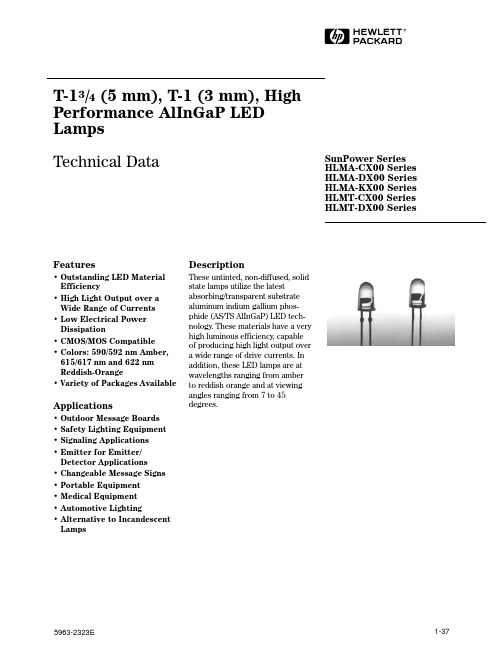
1-37HDescriptionThese untinted, non-diffused, solid state lamps utilize the latest absorbing/transparent substrate aluminum indium gallium phos-phide (AS/TS AlInGaP) LED tech-nology . These materials have a very high luminous efficiency , capable of producing high light output over a wide range of drive currents. In addition, these LED lamps are at wavelengths ranging from amber to reddish orange and at viewing angles ranging from 7 to 45degrees.Features• Outstanding LED Material Efficiency• High Light Output over a Wide Range of Currents • Low Electrical Power Dissipation• CMOS/MOS Compatible • Colors: 590/592 nm Amber,615/617nm and 622 nm Reddish-Orange• Variety of Packages AvailableApplications• Outdoor Message Boards • Safety Lighting Equipment • Signaling Applications • Emitter for Emitter/Detector Applications• Changeable Message Signs • Portable Equipment • Medical Equipment • Automotive Lighting• Alternative to Incandescent LampsSunPower Series HLMA-CX00 Series HLMA-DX00 Series HLMA-KX00 Series HLMT-CX00 Series HLMT-DX00 SeriesT-13/4 (5 mm), T-1 (3 mm), High Performance AlInGaP LED Lamps Technical Data5963-2323E1-38NOTES:1. ALL DIMENSIONS ARE IN MILLIMETERS (INCHES).2. THE LEADS ARE MILD STEEL, SOLDER DIPPED.3. AN EPOXY MENISCUS MAY EXTEND ABOUT 1 MM (0.040") DOWN THE LEADS, UNLESS OTHERWISE NOTED.Package Dimensions1.27 (0.050)NOTESABCAbsolute Maximum Ratings at T A = 25°C(T-13/4 Package)DC Forward Current[1,4,5]...........................................................50 mAPeak Forward Current[2]...........................................................200 mATime Average Input Power[2]...................................................103 mWTransient Forward Current[3] (10 µs Pulse)..............................500 mAReverse Voltage (I R = 100 µA).........................................................5 VOperating Temperature Range..........................................-40 to 100°CStorage Temperature.........................................................-40 to 120°CJunction Temperature.................................................................130°CSoldering Temperature..........................................260°C for 5 seconds[1.59 mm (0.06 in.) below seating plane]Notes:1. Derate linearly as shown in Figure 4.2. Any pulsed operation cannot exceed the Absolute Max Peak Forward Current or theMax Allowable Time Average Power as specified in Figure 5.3. The transient peak current is the maximum nonrecurring peak current the device canwithstand without damaging the LED die and wire bonds.4. Drive Currents between 10 and 30 mA are recommended for best long termperformance.5. Operation at currents below 10 mA is not recommended, please contact yourHewlett-Packard sales representative.Absolute Maximum Ratings at T A = 25°C (T-1 Package)DC Forward Current[1,4,5]...........................................................50 mAPeak Forward Current[2]...........................................................200 mATime Average Input Power[2]...................................................103 mWTransient Forward Current[3] (10 µs Pulse)..............................500 mAReverse Voltage (I R = 100 µA).........................................................5 VOperating Temperature Range..........................................-40 to 100°CStorage Temperature.........................................................-40 to 100°CJunction Temperature..................................................................110°CSolder Temperature................................................260°C for 5 seconds[1.59 mm (0.06 in.) below seating plane]Notes:1. Derate linearly as shown in Figure 4.2. Any pulsed operation cannot exceed the Absolute Max Peak Forward Current or theMax Allowable Time Average Power as specified in Figure 5.3. The transient peak current is the maximum nonrecurring peak current the device canwithstand without damaging the LED die and wire bonds.4. Drive Currents between 10 mA and 30 mA are recommended for best long termperformance.5. Operation at currents below 10 mA is not recommended, please contact yourHewlett-Packard sales representative.1-39Optical Characteristics at T A = 25°CTS-AlInGaP T-13/4Notes:1. The luminous intensity, I V, is measured at the peak of the spatial radiation pattern which may not be aligned with the mechanical axisof the lamp package.2. The dominant wavelength, λd, is derived from the CIE Chromaticity Diagram and represents the color of the device.3. θ1/2 is the off-axis angle where the luminous intensity is 1/2 the peak intensity.4. The luminous intensity, I v, is measured at the mechanical axis of the lamp package. The actual peak of the spatial radiation patternmay not be aligned with this axis.AS-AlInGaP T-13/4Notes:1. The luminous intensity, I V, is measured at the peak of the spatial radiation pattern which may not be aligned with the mechanical axisof the lamp package.2. The dominant wavelength, λd, is derived from the CIE Chromaticity Diagram and represents the color of the device.3. θ1/2 is the off-axis angle where the luminous intensity is 1/2 the peak intensity.4. The luminous intensity, I v, is measured at the mechanical axis of the lamp package. The actual peak of the spatial radiation patternmay not be aligned with this axis.AS-AlInGaP T-1Notes:1. The luminous intensity, I v, is measured at the mechanical axis of the lamp package. The actual peak of the spatial radiation patternmay not be aligned with this axis.2. The dominant wavelength, λd, is derived from the CIE Chromaticity Diagram and represents the color of the device.3. θ1/2 is the off-axis angle where the luminous intensity is 1/2 the peak intensity.1-401-41AS-AlInGaP T-1Speed of Forward ReverseCapacitanceResponse Voltage Breakdown C (pF)τs (ns)Part V F (Volts)V R (Volts)V F = 0,Thermal Time ConstantNumber @ I F = 20 mA @ I R = 100 µA f = 1 MHz Resistance e -t/τs HLMA-Typ. Max.Min.Typ.Typ.R θJ-PIN (°C/W)Typ.KL00 1.9 2.452540290 13KH00 1.9 2.45254029013Electrical Characteristics at T A = 25°CTS-AlInGaP T-13/4Speed of Forward ReverseCapacitanceResponse Voltage Breakdown C (pF)τs (ns)Part V F (Volts)V R (Volts)V F = 0,Thermal Time ConstantNumber @ I F = 20 mA @ I R = 100 µA f = 1 MHz Resistance e -t/τs HLMT-Typ. Max.Min.Typ.Typ.R θJ-PIN (°C/W)Typ.CL00 2.0 2.452570210 13CH00 2.0 2.45257021013DL00 2.0 2.45257026013DH00 2.0 2.45257026013AS-AlInGaP T-13/4Speed of Forward ReverseCapacitanceResponse Voltage Breakdown C (pF)τs (ns)Part V F (Volts)V R (Volts)V F = 0,Thermal Time ConstantNumber @ I F = 20 mA @ I R = 100 µA f = 1 MHz Resistance e -t/τs HLMA-Typ. Max.Min.Typ.Typ.R θJ-PIN (°C/W)Typ.CL00 1.9 2.452540210 13CH00 1.9 2.45254021013DL00 1.9 2.45254026013DH00 1.9 2.452540260 13DG00 1.9 2.452540260131-42Figure 2b. Forward Current vs.Forward Voltage, TS-AlInGaP.Figure 3. Relative Luminous Intensity vs. Forward Current. Derating Based on T J MAX.Figure 4a. Maximum DC Current vs.Ambient Temperature for AS T-13/4Lamps. Derating Based on T J MAX =130°C.T A – AMBIENT TEMPERATURE – °C0I F – F O R W A R D C U R R E N T – m A10203040502040608010012014060T A – AMBIENT TEMPERATURE – °C0I F – F O R W A R D C U R R E N T – m A10203040502040608010012014060Figure 1. Relative Intensity vs. Wavelength.WAVELENGTHR E L A T I V E I N T E N S I T Y1.00.50Figure 2a. Forward Current vs.Forward Voltage, AS-AlInGaP.I F – F O R W A R D C U R R E N T – m A1.00V F – FORWARD VOLTAGE – V2.520012080 1.52.0160 3.0402060100140180I F – F O R W A R D C U R R E N T – m A1.5V F – FORWARD VOLTAGE – V3.01006040 2.02.580 3.520103050709020T A – AMBIENT TEMPERATURE – °C 51535050304510050I F – F O R W A R D C UR R E N T – m A10204090602530407080100504020100I A V G – A V E R A G E C U R R E N T – m AI PEAK – PEAK FORWARD CURRENT – mA30Figure 4c. Maximum Forward Current vs. Ambient Temperature for T-1Lamps. Derating Based on T J Max = 110 °C.Figure 5. Maximum Average Current vs. Peak Forward Current.Figure 4b. Maximum DC Current vs.Ambient Temperature for TS T-13/4Lamps. Derating Based on T J MAX =130°C. 2.52.01.51.00.001050204030I F – DC FORWARD CURRENT – mAR E L A T I V E L U M I N O U S I N T E N S I T Y (N O R M A L I Z E D A T 20 m A )0.51-43N O R M A L I Z E D I N T E N S I T Y1.00.90.80.70.60.50.40.30.20.120°16°12°8°4°0°4°8°12°16°20°θ – ANGULAR DISPLACEMENT – DEGREES18°14°10°6°2°2°6°10°14°18°Figure 6. Normalized Luminous Intensity vs. Angular Displacement,HLMT-CH00/CL00.θ – ANGULAR DISPLACEMENT – DEGREESN O R M A L I Z E D I N T E N S I T Y1.00.90.80.70.60.50.40.30.20.1100°90°80°70°60°50°40°30°20°10°0°10°20°30°40°50°60°70°80°90°100°Figure 8. Normalized Luminous Intensity vs. Angular Displacement, HLMA-KH00/-KL00.Figure 7. Normalized Luminous Intensity vs. Angular Displacement,HLMA-DG00/-DH00/-DL00.N O R M A L I Z E D I N T E N S I T Y1000θ – ANGULAR DISPLACEMENT – DEGREES80605070202018103040161412108426246810121416182090。
伊玛产品类别
10~36VDC
2
三线
NO
DC PNP
200
40
2
PVC
带线
N
Y
N
IP67
否
非齐平
brass
10~36VDC
2
三线
NO
DC NPN
200
40
2
PVC
带线
N
Y
N
IP67
否
齐平
brass
10~36VDC
1
三线
NO
DC PNP
200
40
2
PVC
带线
N
Y
N
IP67
否
非齐平
brass
10~36VDC
产品类别
订货号
感应面
材质
工作
电压
感应
距离mm
电气
设计
输出
负载
电流
外观
尺寸mm
连接
方式
防护
等级
功能
非齐平
PBT+GF
20~250VAC/DC
8
两线
常开
250
80
2米PVC线
IP67
非齐平
PBT+GF
20~250VAC/DC
8
两线
常闭
250
80
2米PVC线
IP67
非齐平
PP+GF
10~36VDC
8
三线
NPN常开
PNP NO/NC,NPN NO/NC
可
智慧型
7 LED
内螺纹
G 1/4
10 bar
四线
西门子参数表

10000 机床轴名称10160 与MMC 通讯的系数10002 NCK 机械轴的逻辑图10165 预留:10008 PLC 控制的轴的最大号码10170 MMC 任务的启动时间限制10010 方式组的通道有效10180 MMC 任务到准备任务的系数10050 基本系统循环时间10185 NCK 运行时间分量10059 Profibus 报警标识符只对内部10190 模拟的换刀时间10060 位置控制循环系数10192 齿轮换挡时间10061 位置控制循环10200 线性位置的计算精度10062 位置控制循环延迟10210 角度位置的计算精度10065 位置设定延迟10220 激活比例系数10070 插补运算器的周期系数10230 机床数据比例系数10071 插补循环10240 基本公制长度单位10072 通讯任务周期的系数10250 INCH 的转换系数10074 PLC 任务比插补任务的系数10260 有效转换的基本设定10075 PLC 循环时间10270 位置表的比例系统10080 取样实际值分配系数10280 对rel.6.3 的比较gt和lt兼容10082 速度设定输出的超前时间10284 不同的显示变量方式10083 位置控制器输出保持时间的偏置10290 OEM 刀具数据的物理单位10085 中断程序段监控时间失效-激活10291 SIEMENS-OEM 刀具数据的单位10088 重新启动延迟10292 OEM 刀沿数据的物理单位10089 缺少总线时脉冲抑制的等待时间10293 SIEMENS-OEM 刀沿数据的单位10090 监控周期的系数10300 NCK 的模拟输入数10091 检查周期时间的显示10310 NCK 的模拟输出数10092 安全数据再确认循环时间显??10320 NCK 模拟输入的比例10093 SPL 文件存取号10330 NCK 模拟输出的比例10094 安全报警禁用级10340 预留:10095 安全方式屏蔽10350 NCK 数字输入字节的数量10096 安全诊断功能10360 NCK 数字输出字节的数量10097 对于SPL-差额停止反应10361 开关量输入输出短路10098 PROFIsafe 通讯的系数10362 NCK 模拟输入的配置10099 PROFI 安全通讯循环时间10364 NCK 模拟输出的配置10100 最大PLC 周期10366 NCK 数字输入配置10110 PLC 确认的平均时间10368 NCK 数字输出的配置10120 PLC 启动的监控时间10380 更新NCK I/O 设备10130 与MMC 通讯的时间限制10382 NCK 外设的引导时间10131 过载时屏幕更新处理10384 NCK I/O 的处理10132在零件程序中监控时间MMC 命令10385 PROFI 安全-地址主控-设备10134 同时发生的MMC 节点数量10386 PROFI 安全-地址输入-设备10136 PCS 位置的显示方式10387 PROFI 安全-地址输出-设备10140 与驱动通讯的时间限制10388 输入分配A_INSE 到PROFIsafe-de10150 与驱动通讯的系数10389 输出分配A_OUTSE 到PROFIsafe-de10390 SPL 外部接口的输入分配10648 底角的名称10392 SPL 外部接口的输出分配10650 插补参数的名称10394 可直接在NC 读取的PLC 输入字节数量10652 定义轮廓角度名称10395 直接读PLC 输入位起始地址10654 定义轮廓半径名称10396 可直接在NC 写入的PLC 输入字节数量10656 定义轮廓斜面名称10397 直接写PLC 输出位起始地址10660 G2/G3 中间坐标点的名称10398 PLCIO 输入循环升级时间10670 位置信息名称10399 用于PLCIO 左最高位/右最高位10672 轴位置信息名称10400 编辑循环输入字节数量10674 多项式编程不带G 功能POLY 编程10410 编译循环输出字节数10700 程序预处理阶段10420 编译循环的NCK 输出10702 块信号停止预防10430 编辑循环的硬件调试屏蔽10704 空运行激活10450 分配软件凸轮到机床轴10706 跳越有效10460 负凸轮1 - 1632的时间响应10707 编程测试模式10461 正凸轮 1 - 1632的时间响应10708 程序段搜索模式10470 I/O 设备上 1 - 8 凸轮的配置10710 更新的设定数据10471 I/O 设备上9 -16 凸轮的配置10712 未配置的NC 代码列表10472 I/O 设备上17 - 24 凸轮的配置10713 带预处理停止的M 代码10473 I/O设备上25 - 32 凸轮的配置10714 复位后M 代码 f.主轴激活10480 NCU 凸轮信号输出的屏蔽10715 M 代码由子程序代替10485 凸轮特性10716 M 代码替换的子程序名称10490 测量的软挡块10717 T 代码替换的子程序名称10530 比较器字节 1 的模拟量输出10718 带参数的M 代码替代10531 比较器字节2 的模拟量输出10719 T 功能替换的参数化10540 比较器字节1 的参数化10720 上电操作方式10541 比较器字节2 的参数化10722 参数更改10600 FRAME框架旋转的输入类型10730 手动JOG键的功能10602 几何轴转换的FRAME 10731 手动JOG键的功能10604 改变几何轴的工作区限制10760 G53,G153,SUPA 的说明10610 镜象参考轴10780 删除TP 编辑启动禁止10612 镜象改变10800 第一M 功能通道同步10613 NCU 全局基础FRAME 复位后激活10802 通道同步的最后M 功能10615 上电后复位全局基础FRAME 10804 M 功能激活ASUP10617 在子程序存储时FRAME 行为10806 M 功能没激活ASUP10618 GEO 轴变化的保护范围10808 中断程序激活ASUP10620 欧拉角的名称10810 G31 P 测量信号结构10630 普通矢量的名称10812 带G68 双刀架10640 方向矢量的名称10814 MACRO 调用的M 功能10642 旋转矢量的名称10815 M 功能macro 调用的子程序名称10644 临时矢量的名称10816 macro 调用的G 功能10646 第二路径方向编程名称10817 G 功能macro 调用的子程序名称10818 ASUP 启动M96的中断数11380 安全集成测试机床数据10820 快速返回的中断数G10.6 11382 地址单元的INTEGER 整数显示10850 OEM-G-代码的最大号码11384 地址单元的REAL 显示10880 合适的CNC 系统定义11386 地址单元的INTEGER 整数输入10881 ISO_3 模式:G 代码系统11388 地址单元的REAL 输入10882 外部NC 语言的用户G 代码表11390 地址单元的内容重写10884 带或不带数值运算命令11398 轴变量服务器出错10886 增量系统11400 激活内部轨迹功能10888 刀具的位置号11410 报警输出的屏蔽10890 外部语言的刀具编程模式11411 报警激活10892 G00 插补11412 报警响应CHAN_NOREADY 有效10900 分度轴表1 位置数11413 报警参数作为文本输出10910 分隔位置表1 11420 记录文件大小KB10920 分度轴表 2 的位置数11430 数字化时的通道定义10930 分隔位置表2 11432 选择3 轴或32 轴数字化11100 辅助功能组的辅助功能数量11450 参数化搜索11110 辅助功能组说明11460 异步往复的模式表单11120 程序全局用户数据PUD系数有效11470 重新配置的属性11140 除GUD 模块以外的地址11480 OB1 中PLC 轨迹数据的缓存深度11200 上电时装载标准数据11481 OB35 中PLC 轨迹数据的缓存深度11210 仅保存修改过的机床数据11482 OB40 中PLC 轨迹数据的缓存深度11220 INI 初始化文件出错时的系统反应11500 受保护的同步动作11230 MD 文件备份的结构11510 最大允许的IPO 负载11240 SDB1000 号11600 固定的BAG 响应11250 Profibus 停机处理11602 ASUP 运行时不考虑停止的原因11270 NC 语言元素的默认值激活11604 ASUP_START_MAS 优先级有效11280 在工件目录处理INI 文件11610 用户定义ASUP 程序激活11290 在DRAM 选择目录11612 用户定义ASUP 编程的保护级11291 DRAM 中选择目录11620 PROG_EVENT 的程序名称11295 记录文件的存储类型11640 使能间隔在MD11300 JOG 方式中的INC 和REF MC_AXCONF_MACHAX_USED11310 方向改变手轮的阀值11649 打开在#MC_AXCONF_MACHAX_USED 中的11320 每个间隔位置的手轮脉冲数保护11322 每个凸轮爪位置的轮廓手轮脉冲11660 可能的电子齿轮箱数量11324 手轮号码在VDI 接口中描述11700 NC 卡代码11330 INC/手轮的增量大小12000 轴进给倍率开关编码11340 第三手轮:驱动类型12010 轴进给倍率系数11342 第三手轮:驱动号/测量电路号12020 灰度- 编码轨迹进给率开关11344 第三手轮:输入模块/测量电路12030 路径进给倍率的系数11346 手轮:12040 灰度码快速运行倍率开关11360 INC 信号影响方式组12050 快速进给的倍率系数12060 灰度码主轴倍率开关13030 模块识别12070 主轴倍率的系数13040 驱动类型12080 回参考点速度的倍率13050 逻辑驱动地址12082 进给倍率13060 Profibus-DP 标准通讯类型12100 二进制编码的倍率限定13070 使用DP 功能12200 在倍率0 时运行13080 驱动类型Profibus12202 直线轴的固定进给率13100 诊断驱动母线12204 旋转轴的固定进给率13200 探头极性改变12205 主轴固定转速13201 带数字输出的测量脉冲模拟12510 在NCU 组中的NCU 代码13210 带Profibus 驱动的测头操作类型12520 NCU 号,总线终止阻抗有效13220 探头延迟时间12540 联接总线波特率14000 SSI 绝对值编码器的波特率12550 信息存储区重复的最大量14010 FIPO 启动延迟12701 在轴系列1 中的轴清单14020 SSI 延时12702 在轴系列 2 中的轴清单14500 输入字节的个数从PLC12703 在轴系列3 中的轴清单14502 输出字节的个数到PLC12704 在轴系列4 中的轴清单14504 用户数据的号INT12705 在轴系列5 中的轴清单14506 用户数据的号HEX12706 在轴系列 6 中的轴清单14508 用户数据的号FLOAT12707 在轴系列7 中的轴清单14510 用户数据INT12708 在轴系列8 中的轴清单14512 用户数据HEX12709 在轴系列9 中的轴清单14514 用户数据FLOAT12710 在轴系列10 中的轴清单14516 用户数据HEX12711 在轴系列11 中的轴清单17200 全局MMC 信息没有物理单元12712 在轴系列12 中的轴清单17201 全局MMC 状态信息没有物理单元12713 在轴系列13 中的轴清单17500 替换刀具的最大号12714 在轴系列14 中的轴清单17510 卸载后刀具- 数据的运行状态12715 在轴系列15 中的轴清单17520 产生新刀具:默认设置12716 在轴系列16 中的轴清单17530 对于HMI 标记的刀具-数据-变化12750 轴系列名称17600 REORG 中log 存储最优化深度12970 数字PLC 输入地址的起始地址18000 更新PLC 接口12971 数字输入地址号18040 PCMCIA 卡的版本和日期12974 数字PLC 输出地址的起始地址18050 自由无缓冲内存bytes12975 数字输出地址号18060 自由缓冲内存bytes。
HLMP-C517-X0000中文资料
DescriptionThese non-diffused lamps are designed to produce a bright light source and smooth radiationpattern. A slight tint is added to the lens for easy color identification.This lamp has been designed with aHLMP-C115, HLMP-C117, HLMP-C123, HLMP-C215, HLMP-C223,HLMP-C315, HLMP-C323, HLMP-C415, HLMP-C423, HLMP-C515,HLMP-C523, HLMP-C615, HLMP-C623Features•Very high intensity •Exceptional uniformity •Microtint lens for color identification•Consistent viewability All colors: AlGaAs RedHigh Efficiency Red Yellow Orange GreenEmerald Green •15° and 25° family•Tape and reel options available •Binned for color and intensity Applications•Ideal for backlighting front panels*•Used for lighting switches •Adapted for indoor and outdoor signsAgilentT-13/4 Super Ultra-Bright LED LampsData Sheet20mil lead frame, enhanced flange, and tight meniscus controls, making it compatible with radial lead automated insertion equipment.Selection GuidePart Number Luminous Intensity Iv (mcd) Color2θ1/2[1]Standoff Leads HLMP-Min.Max.DH AS AlGaAs15No C115290.0–C115-O00xx290.0–C115-OP0xx290.01000.0Yes C117-OP0xx290.01000.025No C12390.2–C123-L00xx90.2–Red15No C215138.0–C215-M00xx138.0–C215-MN0xx138.0400.025No C22390.2–C223-L00xx90.2–C223-MN0xx138.0400.0 Yellow15No C315147.0–C315-L00xx147.0–C315-LM0xx147.0424.025No C32396.2–C323-K00xx96.2–C323-KL0xx96.2294.0 Orange15No C415138.0–C415-M00xx138.0–C415-M0D0xx138.0–C415-MN0xx138.0400.025No C42390.2–C423-L00xx90.2–C423-LM0xx90.2276.0 Green15No C515170.0–C515-L00xx170.0C515-LM0xx170.0490.025No C52369.8–C523-J00xx69.8–C523-KL0xx111.7340.0 Emerald Green15No C61517.0–C615-G00xx17.0–25No C623 6.7–C623-E00xx 6.7–Part Numbering SystemHLMP - C x xx - x x x xxMechanical Options00: Bulk01: Tape & Reel, Crimped Leads02: Tape & Reel, Straight LeadsB2: Right Angle Housing, Even LeadsUQ: Ammo Pack, Horizontal LeadsColor Bin Options0: Full Color Bin DistributionD: Color Bins 4 & 5 onlyMaximum Iv Bin Options0: Open (No Maximum Limit)Others: Please refer to the Iv Bin TableMinimum Iv Bin OptionsPlease refer to the Iv Bin TableViewing Angle & Standoffs Options15: 15 Degree, without Standoffs17: 15 Degree, with Standoffs23: 25 Degree, without StandoffsColor Options1. AS AlGaAs Red2. High Efficiency Red3. Yellow4. Orange5. Green6. Emerald GreenPackage OptionsC: T-1 3/4 (5 mm)Absolute Maximum Ratings at T A = 25°CHighHighDH AS Efficiency Performance AlGaAs Red and Green and ParameterRed Orange Yellow Emerald Green Units DC Forward Current [1]30302030mA Transient Forward Current [2]500500500500mA (10 µsec Pulse)Reverse Voltage (Ir = 100 µA)5555V LED Junction Temperature 110110110110°C Operating Temperature Range –20 to +100–55 to +100–20 to +100°C Storage Temperature Range –55 to +100°CWave Soldering Temperature 250°C for 3 seconds [1.59 mm (0.063 in.) from body]Lead Solder Dipping Temperature 260°C for 5 seconds[1.59 mm (0.063 in.) from body]Notes:1. See Figure 5 for maximum current derating vs. ambient temperature.2. The transient current is the maximum nonrecurring peak current the device can withstand without damaging the LED die and wire bond.Package DimensionsHLMP-Cx15 and HLMP-Cx23HLMP-Cx17(0.039)NOTES:1. ALL DIMENSIONS ARE IN MILLIMETERS (INCHES).2. LEADS ARE MILD STEEL, SOLDER DIPPED.3. AN EPOXY MENISCUS MAY EXTEND ABOUT 0.5 mm (0.020 in.) DOWN THE LEADS.± 0.20± 0.008)Electrical Characteristics at T A = 25°CForward Reverse Capacitance Speed of ResponseVoltage Breakdown C (pF)Thermalτs (ns)Vf (Volts)Vr (Volts)Vf = 0Resistance Time Constant@ If = 20 mA@ Ir = 100 µA f = 1 MHz RθJ-PIN e-t/τsPart Number Typ.Max.Min.Typ.(°C/W)Typ.HLMP-C115 1.8 2.253021030HLMP-C117HLMP-C123HLMP-C215 1.9 2.651121090HLMP-C223HLMP-C315 2.1 2.651521090HLMP-C323HLMP-C415 1.9 2.654210280HLMP-C423HLMP-C515 2.2 3.0518210260HLMP-C523HLMP-C615 2.2 3.0518210260HLMP-C623Optical Characteristics at T A = 25°CLuminous Color,ViewingIntensity Peak Dominant Angle LuminousIv (mcd)Wavelength Wavelength2θ1/2Efficacy@ 20 mA[1]λpeak (nm)λd[2] (nm)(Degrees)[3]ηvPart Number Min.Typ.Typ.Typ.Typ.(lm/w) HLMP-C1152906006456371180HLMP-C117HLMP-C1239020026HLMP-C215138300635626171459017023HLMP-C315146300583585175009617025HLMP-C415138300600602173809017023HLMP-C515170300568570205956917028HLMP-C61517455585602065662728Notes:1. The luminous intensity, Iv, is measured at the mechanical axis of the lamp package. The actual peak of the spatial radiation pattern may not bealigned with this axis.2. The dominant wavelength, λd, is derived from the CIE Chromaticity Diagram and represents the color of the device.3. 2θ1/2 is the off-axis angle where the luminous intensity is 1/2 the on-axis intensity.Figure 1. Relative intensity vs. wavelength.Figure 2. Forward current vs. forward voltage (non-resistor lamp).Figure 3. Relative luminous intensity vs. forward current.WAVELENGTH – nmR E L A T I V E I N T E N S I T Y1.00.50I F – F O R W A R DC U R R E N T – m AV F – FORWARD VOLTAGE – VI F – F O R W A R D C U R R E N T – m AV F – FORWARD VOLTAGE – VHIGH EFFICIENCY RED, ORANGE,YELLOW, AND HIGH PERFORMANCEGREEN, EMERALD GREENR E L A T I V E L U M I N O U S I N TE N S I T Y (N O R M A L I Z E D A T 20 m A )I F – DC FORWARD CURRENT – mA R E L A T I V E L U M I N O U S I N T E N S I T Y (N O R M A L I Z E D A T 20 m A )0I DC – DC CURRENT PER LED – mA10201.60.80.4515301.2250.20.61.01.4HER, ORANGE, YELLOW, AND HIGH PERFORMANCE GREEN, EMERALD GREENFigure 5. Maximum forward dc current vs. ambient temperature. Derating based on T j MAX = 110°C.Figure 4. Relative efficiency (luminous intensity per unit current) vs. peak current.Figure 6. Relative luminous intensity vs. angular displacement. 15 degree family.R E L A T I V E E F F I C I E N C Y (N O R M A L I Z E D A T 20 m A )0I PEAK – PEAK FORWARD CURRENT – mA0.60.8300201001.21.00.20.45020010DH As AlGaAs REDηP E A K – R E L A T I V E E F F I C I E N C Y (N O R M A L I Z E D A T 20 m A )I PEAK – PEAK FORWARD CURRENT – mAHER, ORANGE, YELLOW, HIGHPERFORMANCE GREEN, EMERALD GREENI F – F O R W A R D C U R R E NT – m AT A – AMBIENT TEMPERATURE – °C DH As AlGaAs REDI F – F O R W A R D C U R R E N T – m AT A – AMBIENT TEMPERATURE – °CHER, ORANGE, YELLOW, AND HIGH PERFORMANCE GREEN, EMERALD GREEN N O R M A L I Z E D L U M I N O U S I N T E N S I T Y10ANGULAR DISPLACEMENT – DEGREES0.80.60.50.70.2450.10.30.4403530252010515-5-10-15-20-25-30-35-40-450.9Figure 7. Relative luminous intensity vs. angular displacement. 25 degree family.Intensity Bin Limits Intensity Range (mcd)ColorBin Min.Max.L 101.5162.4M 162.4234.6N 234.6340.0O 340.0540.0P 540.0850.0Q 850.01200.0R 1200.01700.0Red/OrangeS 1700.02400.0T 2400.03400.0U 3400.04900.0V 4900.07100.0W 7100.010200.0X 10200.014800.0Y 14800.021400.0Z 21400.030900.0L 173.2250.0M 250.0360.0N 360.0510.0O 510.0800.0P 800.01250.0YellowQ 1250.01800.0R 1800.02900.0S 2900.04700.0T 4700.07200.0U 7200.011700.0V 11700.018000.0W18000.027000.0N O R M A L I Z E D L U M I N O U S I N T E N S I T Y10ANGULAR DISPLACEMENT – DEGREES0.80.60.50.70.2450.10.30.4403530252010515-5-10-15-20-25-30-35-40-450.9Intensity Bin Limits, continuedIntensity Range (mcd) Color Bin Min.Max.E7.612.0F12.019.1G19.130.7H30.749.1I49.178.5J78.5125.7K125.7201.1L201.1289.0 Green/M289.0417.0 Emerald Green N417.0680.0O680.01100.0P1100.01800.0Q1800.02700.0R2700.04300.0S4300.06800.0T6800.010800.0U10800.016000.0V16000.025000.0W25000.040000.0 Maximum tolerance for each bin limit is ± 18%.Color CategoriesLambda (nm)Color Category #Min.Max.6561.5564.55564.5567.5 Green4567.5570.53570.5573.52573.5576.51582.0584.53584.5587.0 Yellow2587.0589.54589.5592.05592.0593.01597.0599.52599.5602.03602.0604.5 Orange4604.5607.55607.5610.56610.5613.57613.5616.58616.5619.5 Tolerance for each bin limit is ± 0.5 nm.Mechanical Option MatrixMechanical Option Code Definition00Bulk Packaging, minimum increment 500 pcs/bag01Tape & Reel, crimped leads, minimum increment 1300 pcs/bag02Tape & Reel, straight leads, minimum increment 1300 pcs/bagB2Right Angle Housing, even leads, minimum increment 500 pcs/bagUQ Ammo Pack, horizontal leads, in 1K minimum incrementNote:All categories are established for classification of products. Products may not be available in all categories. Please contact your local Agilent representative for further clarification/information./semiconductorsFor product information and a complete list ofdistributors, please go to our web site.For technical assistance call:Americas/Canada: +1 (800) 235-0312 or(916) 788-6763Europe: +49 (0) 6441 92460China: 10800 650 0017Hong Kong: (+65) 6756 2394India, Australia, New Zealand: (+65) 6755 1939Japan: (+81 3) 3335-8152 (Domestic/Interna-tional), or 0120-61-1280 (Domestic Only)Korea: (+65) 6755 1989Singapore, Malaysia, Vietnam, Thailand,Philippines, Indonesia: (+65) 6755 2044Taiwan: (+65) 6755 1843Data subject to change.Copyright © 2004 Agilent Technologies, Inc.Obsoletes 5965-6165ENovember 11, 20045988-2149EN。
D217中文资料

Pin Single
Dual
1
+Vin
+Vin
2
-Vin
-Vin
4
-Vout
-Vout
5 No Pin Common
6
+Vout +Vout
Mechanical Dimensions
79
1,000
67
500
78
500
85
500
83
500
77
500
82
500
82
500
74
200
77
200
81
200
82
200
77
200
81
200
84
200
70
100
77
100
81
100
82
100
76
100
81
100
82
100
Notes: 1. Output load regulation is specified for a load change of 20% to 100%. 2. When measuring output ripple, it is recommended that an external ceramic capacitor (approx 10 µF)
(%, Max) 12 12 8 8 12 8 8 8 8 8 8 8 8 8 8 8 8 8 8 8 8 8 8 8 8 8 8 8
Efficiency (%, Typ)
Fuse Rating Slow-Blow
(mA)
75
1,000
ILD217中文资料

Emitter Peak Reverse Voltage .....................................6.0 V Peak Pulsed Current (1 µs, 300 pps) .................1 A Continuous Forward Current per Channel ....30 mA Power Dissipation at 25°C............................45 mW Derate Linearly from 25°C......................0.5 mW/°C
CTR (nonsat) normalized @ If=10ma Vce=10v Ta=25°C
100
Package Power Dissipation (mw)
Figure 7. Power dissipation versus ambient temperature
200 Total pkg
150
元器件交易网
FEATURES • Two Channel Coupler • Industry Standard SOIC-8 Surface Mountable
Package • Standard Lead Spacing of .05" • Available in Tape and Reel Option
.230±.002 (4.88±.05)
Pin 1
Anode 1
CL
.154±.002 (3.91±.05)
Cathode Anode
2 3
Cathode 4
派克液压中文样本

液压注意 – 用户方责任 错误或不当地选择或使用本样本或有关资料阐述的产品,可能会导致人生伤亡及财产损失! 本样本以及其它由派克汉尼汾公司及其子公司、销售公司与授权分销商所提供的资料,仅供用户专业技术人员在对产品和系统的选型进行深入调查考证时参考。
用户应全面分析自身设备的运行工况、适用的工业标准,并仔细查阅现行的样本,以详细地了解产品及系统的相关信息,通过自己的分析和试验,对产品及系统的独立的最终选择负责,确保能满足自身设备的所有性能、耐用性、维修型、安全性以及预警功能等要求。
对于派克或其子公司或授权分销商而言,应负责按用户提供的技术资料和规范,选择和提供适当的元件或系统,而用户则应负责确定这些技术资料和规范对其设备的所有运行工况和能合理预见的使用工况是否充分和准确。
目录目录页次概述 1 订货代号 2 技术参数 4 变量控制器 5 控制选项 “C”, 压力限定(恒压)变量控制器 5 控制选项 “L”, 负载传感及压力限定变量控制器 6 控制选项 “AM”, 带遥控口的标准型先导式压力限定变量控制器 7 控制选项 “AN”, 带ISO 4401 NG06先导阀安装界面的先导式压力限定变量控制器 8 控制选项 “AE”及“AF”, 带电磁比例调节的先导式压力限定变量控制器 9 控制选项 “AMT”, “ALT”及“LOT”, 带最高压力限定的扭矩限定(恒功率)变量控制器 10 P1性能特性 11典型流量特性 11 典型总效率特性 13 典型轴输入功率特性 15 典型噪声特性 18 典型轴承寿命 20 PD性能特性 22典型流量特性 22 典型总效率特性 24 典型轴输入功率特性 26 典型噪声特性 29 典型轴承寿命 31 安装尺寸 33 P1/PD 018 33 P1/PD 028 36 P1/PD 045 40 P1/PD 060 44 P1/PD 075 49 P1/PD 100 54 P1/PD 140 59 变量控制器安装尺寸 65 可提供的扩展的液压产品 75派克汉尼汾备记派克汉尼汾概述简介, 优点派克汉尼汾简介 • 开式回路用轴向柱塞式变量液压泵 • 中压,连续工作压力280 bar • 高驱动转速型,适用于行走机械; 低噪声型,适用于工业应用 • 静音及高效的控制效能 优点 • 总结构尺寸紧凑 • 低噪声• 流量脉动小,进一步降低噪声• 采用弹性密封,不使用密封垫,从而避免外泄漏的产生• 总效率高,功耗小,减小发热• 采用带无泄漏调节装的简单变量控制器 • 符合SAE 及ISO 标准的安装法兰及油口 • 采用圆锥滚柱轴承,使用寿命长 • 全功率后驱动能力• 后部或侧面油口配置可选• 泄油口的配置对水平安装及驱动轴向上垂直安装均适用• 带有最大及最小排量调节选项 • 具有壳体至吸口单向阀选项,可延长轴封寿命 • 使用、维修方便 脉动容腔技术下列图表所示为侧向油口配置P1/PD 18, 28及45泵采用 “脉动容腔” 技术的效果,脉动容腔可降低泵出口处的压力脉动幅值40-60%,这样,无需增加成本来加装噪声缓冲元件,便可大大降低液压系统的整体噪声,P1系列 PD 系列出口压力p / bar平均压力脉动 / b a rP1 045出口压力脉动2600 rpm 无脉动容腔2600 rpm 带脉动容腔订货代号18 ml, 28 ml, 45ml派克汉尼汾P 类型 01 驱动轴 转向R 5密封材料E 油口配置0 壳体-吸口 单向阀 0 排量调节 018 排量 S 安装法兰 及油口 S 轴封 M 应用范围A 设计系列0 通轴驱动选项 C0控制选项0附加控制选项 00油漆 00修改代号系列 P D * 仅适用于045排量, “S”型安装法兰及油口00 标准型, 无修改M2 按要求修改 代号修改代号 * 适用于028及045排量 ** 仅适用于045排量 代号设计系列 A 现行设计系列5 氟碳橡胶 (FPM) 代号密封材料 A 82-2 SAE A M33x2 M27x2 BSPP 1/4”, 3/8” 101-2 SAE B M42x2 M27x2 BSPP 1/4”, 1/2” 101-2SAE B M48x2M33x2Ø38/25DN51/25BSPP 1/4”, 1/2”B ISO M33x2 M27x2 BSPP 1/4”,3/8”ISO M42x2 M27x2 BSPP 1/4”, 1/2” ISO M48x2M33x2Ø38/25DN51/25BSPP 1/4”, 1/2”代号 018排量 028排量 045排量 安装法兰及油口 安装 法兰 螺纹 油口 辅助 油口 安装 法兰 螺纹 油口 辅助 油口 安装法兰螺纹油口法兰 油口辅助 油口 S 82-2 SAE A SAE 16/12 SAE 4/6 101-2 SAE B SAE 20/12 SAE 4/8 101-2SAE B SAE 24/16Ø38/2561系列SAE 4/10M ISO M33x2 M27x2 M12x1.5 M16x1.5 ISO M42x2 M27x2 M12x1.5 M22x1.5 ISO M48x2M33x2Ø38/25DN51/25M12x1.5M22x1.5代号 018驱动轴 028驱动轴 045驱动轴 01 SAE A 11T 花键SAE B-B 15T 花键 SAE B-B 15T 花键02 SAE 19-1平键Ø0.75” SAE B-B 平键Ø1” SAE B-B 平键Ø1” 08— SAE B 13T 花键 SAE B 13T 花键 04 ISO/DIN 平键, Ø20ISO/DIN 平键, Ø25ISO/DIN 平键, Ø25 06 SAE A 9T 花键— — PD 工业液压用 代号 系列P1 行走机械用 代号 排量 018 18 ml/rev (1.10 in 3/rev) 028 28 ml/rev (1.71 in 3/rev) 045 45 ml/rev (2.75 in 3/rev) 代号 类型 P 开式回路用变量柱塞泵 U*通用 代号应用范围 S 工业液压 (PD) M 行走机械 (P1) R 顺时针 (右转)L 逆时针 (左转)代号 转向 代号 轴封 S 单唇轴封 * 并不具有控制功能,仅在运输时予以防护,详情见第7页的控制说明。
HLMP-PXXX中文资料

1-174HDome PackagesThe HLMP-6XXX Series dome lamps for use as indicators use a tinted, diffused lens to provide a wide viewing angle with a high on-off contrast ratio. High brightness lamps use anuntinted, nondiffused lens to provide a high luminous intensity within a narrow radiation pattern.ArraysThe HLMP-66XX Seriessubminiature lamp arrays are available in lengths of 3 to 8elements per array. Theluminous intensity is matched within an array to assure a 2.1to 1.0 ratio.Resistor LampsThe HLMP-6XXX Series 5 volt subminiature lamps with built in current limiting resistors are for use in applications where space is at a premium.Lead ConfigurationsAll of these devices are made by encapsulating LED chips onaxial lead frames to form molded epoxy subminiature lamppackages. A variety of package configuration options is avail-able. These include specialFeatures• Subminiature Flat Top PackageIdeal for Backlighting and Light Piping Applications • Subminiature Dome PackageDiffused Dome for Wide Viewing AngleNondiffused Dome for High Brightness • Arrays• TTL and LSTTLCompatible 5 Volt Resistor Lamps• Available in Six Colors • Ideal for Space Limited Applications • Axial Leads• Available with LeadConfigurations for Surface Mount and Through Hole PC Board MountingDescriptionFlat Top PackageThe HLMP-PXXX Series flat top lamps use an untinted, non-diffused, truncated lens toprovide a wide radiation pattern that is necessary for use in backlighting applications. The flat top lamps are also ideal for use as emitters in light pipe applications.Subminiature LED Lamps Technical Datasurface mount lead configura-tions, gull wing, yoke lead or Z-bend. Right angle lead bends at 2.54 mm (0.100 inch) and 5.08mm (0.200 inch) center spacing are available for through hole mounting. For more information refer to Standard SMT and Through Hole Lead Bend Options for Subminiature LED Lamps data sheet.HLMP-PXXX Series HLMP-QXXX Series HLMP-6XXX SeriesHLMP-70XX Series5964-9350E1-175Device Selection Guide Part Number: HLMP-XXXXPackage Dimensions(A) Flat Top LampsNOTES:1. ALL DIMENSIONS ARE IN MILLIMETERS (INCHES).2. PROTRUDING SUPPORT TAB IS CONNECTED TO CATHODE LEAD.*Refer to Figure 1 for design concerns.1-176Package Dimensions (cont.)(B) Diffused and NondiffusedFigure 1. Proper Right Angle Mounting to a PC Board to Prevent Protruding Cathode Tab from Shorting to AnodeConnection.NOTES:1. ALL DIMENSIONS ARE IN MILLIMETERS (INCHES).2. PROTRUDING SUPPORT TAB IS CONNECTED TO CATHODE LEAD.*Refer to Figure 1 for design concerns.(C) ArraysNOTES:1. ALL DIMENSIONS ARE IN MILLIMETERS (INCHES).2. PROTRUDING SUPPORT TAB IS CONNECTED TO CATHODE LEAD.1-177DH AS High HighStandard AlGaAs Eff.Perf.EmeraldParameterRedRed Red Orange Yellow Green Green Units DC Forward Current [1]50303030203030mA Peak Forward Current [2]10003009090609090mA DC Forward Voltage 6666V (Resistor Lamps Only)Reverse Voltage (I R = 100 µA)5555555V Transient Forward Current [3]2000500500500500500500mA(10 µs Pulse)Operating Temperature Range:-55 to -40 to -55 to +100-40 to -20 to Non-Resistor Lamps +100+100+100+100°CResistor Lamps-40 to +85-20 to +85Storage Temperature Range °CFor Thru Hole Devices260°C for 5 SecondsWave Soldering Temperature [1.6 mm (0.063 in.) from body]For Surface Mount Devices:Convective IR 235°C for 90 Seconds Vapor Phase215°C for 3 MinutesAbsolute Maximum Ratings at T A = 25°C-55 to +100Notes:1. See Figure 5 for current derating vs. ambient temperature. Derating is not applicable to resistor lamps.2. Refer to Figure 6 showing Max. Tolerable Peak Current vs. Pulse Duration to establish pulsed operating conditions.3. The transient peak current is the maximum non-recurring peak current the device can withstand without failure. Do not operate these lamps at this high current.Electrical/Optical Characteristics, TA= 25°CStandard RedDeviceHLMP-Parameter Symbol Min.Typ.Max.Units Test Conditions 60000.5 1.26001Luminous Intensity[1]Iv 1.3 3.2mcd IF= 10 mA6203 to0.5 1.2 6208Forward Voltage VF 1.4 1.6 2.0V IF= 10 mAAll Reverse Breakdown VR 5.012.0V IR= 100 µAVoltageP005Included Angle Between125Half Intensity Points[2]2θ1/2Deg.All90OthersPeak WavelengthλPEAK655nmDominant Wavelength[3]λd640nmSpectral Line Half Width∆λ1/224nmAll Speed of Responseτs15nsCapacitance C100pF VF= 0; f = 1 MHzThermal Resistance RθJ-PIN 170°C/W Junction-to-CathodeLeadLuminous Efficacy[4]ηv65lm/W1-1781-179Device HLMP-ParameterSymbolMin.Typ.Max.Units Test ConditionsP102 4.020.0P1058.630.0Q10122.045.0Q105Luminous IntensityI v22.055.0mcdQ150 1.0 1.8Q155 2.04.0Q101 1.8 2.2I F = 20 mA P205/P505Forward VoltageV F1.82.2V Q101/Q105Q150/Q1551.6 1.8I F = 1 mA All Reverse Breakdown V R5.015.0V I R = 100 µA VoltageP105125Q101/Q150Included Angle Between 2θ1/290Deg.Half Intensity Points [2]Q105/Q15528Peak Wavelength λPEAK 645nm Measured at PeakDominant Wavelength [3]λd 637nm Spectral Line Half Width∆λ1/220nm AllSpeed of Response τs 30ns Exponential Time Constant; e -t/τCapacitance C 30pF V F = 0; f = 1 MHz Thermal Resistance R θJ-PIN170°C/W Junction-to Cathode Lead Luminous Efficacy [4]ηv80lm/WDH AS AlGaAs Red I F = 1 mA I F = 20 mA sDeviceHLMP-Parameter Symbol Min.Typ.Max.Units Test Conditions P202 1.0 5.0P205 1.08.06300 1.010.0IF= 10 mA6305 3.424.07000Luminous Intensity[1]Iv 0.4 1.0mcd IF= 2 mA6600 1.3 5.0VF= 5.0 Volts 66200.8 2.06653 to 1.0 3.0IF = 10 mA6658All Forward Voltage VF 1.5 1.8 3.0V IF= 10 mA(Nonresistor Lamps)66009.613.0I F mA VF= 5.0 V6620 3.5 5.0All Reverse Breakdown VR 5.030.0V IR= 100 µAVoltageP2051256305Included Angle Between2θ1/228Deg.Half Intensity Points[2]All90DiffusedPeak WavelengthλPEAK635nm Measured at PeakDominant Wavelength[3]λd626nmSpectral Line Half Width∆λ1/240nmAll Speed of Responseτs90nsCapacitance C11pF VF= 0; f = 1 MHzThermal Resistance RθJ-PIN 170°C/W Junction-to-CathodeLeadLuminous Efficacy[4]ηv 145lm/WHigh Efficiency RedForward Current(Resistor Lamps)1-180DeviceHLMP-Parameter Symbol Min.Typ.Max.Units Test Conditions P402 1.0 4.0P405Luminous Intensity Iv 1.06mcd IF= 10 mAQ400 1.08Forward Voltage VF 1.5 1.9 3.0V IF= 10 mAAll Reverse Breakdown VR 5.030.0V IR= 100 µAVoltageP405Included Angle Between125Half Intensity Points[2]2θ1/2Deg.Q40090Peak WavelengthλPEAK600nmDominant Wavelength[3]λd602nm Measured at PeakSpectral Line Half Width∆λ1/240nmAll Speed of Responseτs260nsCapacitance C4pF VF= 0; f = 1 MHzThermal Resistance RθJ-PIN 170°C/W Junction-to-CathodeLeadLuminous Efficacy[4]ηv 380lm/WOrange1-181YellowDeviceHLMP-Parameter Symbol Min.Typ.Max.Units Test Conditions P302 1.0 3.0P305 1.0 4.0IF = 10 mA6400 1.09.06405Luminous Intensity[1]Iv3.620mcd70190.40.6IF= 2 mA6700 1.4 5.0VF= 5.0 Volts 67200.9 2.06753 to 1.0 3.0IF = 10 mA6758All Forward Voltage VF 2.0 2.4V IF= 10 mA(Nonresistor Lamps)67009.613.0Forward Current IF mA VF= 5.0 V6720(Resistor Lamps) 3.5 5.0All Reverse Breakdown VR 5.050.0VVoltageP3051256405Included Angle Between2θ1/228Deg.Half Intensity Points[2]All90DiffusedPeak WavelengthλPEAK583nm Measured at PeakDominant Wavelength[3]λd585nmSpectral Line Half Width∆λ1/236nmAll Speed of Responseτs90nsCapacitance C15pF VF= 0; f = 1 MHzThermal Resistance RθJ-PIN 170°C/W Junction-to-CathodeLeadLuminous Efficacy[4]ηv500lm/W1-1821-183High Performance Green Device HLMP-ParameterSymbolMin.Typ.Max.Units Test ConditionsP502 1.0 3.0P505 1.0 5.06500 1.07.0I F = 10 mA6505 4.220.07040Luminous Intensity [1]I v0.40.6mcdI F = 2 mA 6800 1.6 5.0V F = 5.0 Volts 68200.8 2.06853 to 1.03.0I F = 10 mA 6858All Forward Voltage V F2.1 2.7VI F = 10 mA(Nonresistor Lamps)68009.613.0Forward Current I F mAV F = 5.0 V 6820(Resistor Lamps) 3.5 5.0All Reverse Breakdown V R5.050.0VI R = 100 µA VoltageP5051256505Included Angle Between 2θ1/228Deg.Half Intensity Points [2]All 90DiffusedPeak Wavelength λPEAK 565nm Dominant Wavelength [3]λd 569nm Spectral Line Half Width∆λ1/228nm AllSpeed of Response τs 500ns Capacitance C 18pF V F = 0; f = 1 MHz Thermal Resistance R θJ-PIN170°C/W Junction-to-Cathode LeadLuminous Efficacy [4]ηv595lm/WNotes:1. The luminous intensity for arrays is tested to assure a2.1 to 1.0 matching between elements. The average luminous intensity for an array determines its light output category bin. Arrays are binned for luminous intensity to allow I v matching between arrays.2. θ1/2 is the off-axis angle where the luminous intensity is half the on-axis value.3. Dominant wavelength, λd , is derived from the CIE Chromaticity Diagram and represents the single wavelength that defines the color of the device.4. Radiant intensity, I e , in watts/steradian, may be calculated from the equation I e =I v /ηv , where I v is the luminous intensity in candelas and ηv is the luminous efficacy in lumens/watt.DeviceHLMP-Parameter Symbol Min.Typ.Max.Units Test ConditionsP605Luminous Intensity Iv 1.0 1.5mcd IF= 10 mAQ600 1.0 1.5Forward Voltage VF 2.2 3.0V IF= 10 mAReverse Breakdown VR 5.0V IR= 100 µAVoltageP605Included Angle Between125Half Intensity Points[2]2θ1/2Deg.Q60090Peak WavelengthλPEAK558nmDominant Wavelength[3]λd560nm Measured at PeakSpectral Line Half Width∆λ1/224nmP605/Q600Speed of Responseτs3100nsCapacitance C35pF VF= 0; f = 1 MHzThermal Resistance RθJ-PIN 170°C/W Junction-to-CathodeLeadLuminous Efficacy[4]ηv 656lm/WEmerald Green[1]Note:1. Please refer to Application Note 1061 for information comparing stnadard green and emerald green light ouptut degradation.1-1841-185Standard Red, DH As AlGaAs Red Standard Red and DH ASAlGaAs RedHigh Efficiency Red, Orange,Yellow, and High Performance GreenHER, Orange, Yellow, and High Performance Green,and Emerald GreenLow CurrentFigure 1. Relative Intensity vs. Wavelength.Figure 2. Forward Current vs. Forward Voltage. (Non-Resistor Lamp)Figure 3. Relative Luminous Intensity vs. Forward Current. (Non-Resistor Lamp)1-186Figure 4. Relative Efficiency (Luminous Intensity per Unit Current) vs. Peak Current (Non-Resistor Lamps).Figure 5. Maximum Forward dc Current vs. Ambient Temperature. Derating Based on T J MAX = 110°C (Non-Resistor Lamps).Figure 6. Maximum Tolerable Peak Current vs. Pulse Duration. (I DC MAX as per MAX Ratings) (Non-Resistor Lamps).Standard RedDH As AlGaAs RedStandard Red HER, Orange, Yellow, and HighPerformance GreenDH As AlGaAs RedHER, Orange, Yellow, and High Performance Green,and Emerald Green1-187Figure 9. Relative Intensity vs. Angular Displacement.Figure 7. Resistor Lamp Forward Current vs. Forward Voltage.Figure 8. Resistor Lamp Luminous Intensity vs.Forward Voltage.。
维修提醒器217 - 主要内容说明书
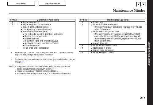
Maintenance Minder217:See information on maintenance and emissions warranty in the first column on page .Independent of the maintenance minder indicator in the information display,replace the brake fluid every 3years.Adjust the valves during services A,B,1,2,or 3only if they are noisy.Inspect idle speed every 160,000miles (256,000km).NOTE:214MaintenanceMinderMaintenance Record218mi mi mi mi mi mi mi mi mi mi mi mi mi mi Maintenance PerformedAB12345A B 12345A B 12345A B 12345A B 12345A B 12345A B 12345Signature DateMaintenance PerformedAB12345AB12345AB12345AB12345AB12345AB12345AB12345Signature DateMileagekm km km km km km kmMileagekm km km km km km kmYou or the servicing dealer can record all completed maintenance here.When maintenance is performed,record the mileage,circle the coded item(s)completed,and write in any other non-coded items (such as brake fluid replacement)below the codes.Keep the receipts for all work done on your vehicle.Maintenance can also be recorded in your Honda service historybooklet.Maintenance RecordMaintenance219mi mi mi mi mi mi mi mi mi mi mi mi mi mi Maintenance PerformedAB12345A B 12345A B 12345A B 12345A B 12345A B 12345A B 12345Signature DateMaintenance PerformedAB12345AB12345AB12345AB12345A B 12345A B 12345A B 12345Signature DateMileagekm km km km km km kmMileagekm km km km km kmkmFluid LocationsDX,Canadian DX-G,LX,and EX models220Fluid LocationsSi modelMaintenance221Oil is a major contributor to your engine’s performance and longevity.Always use a premium-grade detergent oil displaying the APICertification Seal.This seal indicates the oil is energy conserving,and that it meets the American Petroleum Institute’s latest requirements.It is highly recommended that you use Honda Motor Oil in your vehicle for optimum engine protection.Unscrew and remove the engine oil fill cap on the valve cover.Pour in the oil slowly and carefully so you do not spill any.Clean up any spills immediately.Spilled oil coulddamage components in the engine compartment.Recommended Engine Oil Adding Engine Oil222。
伊顿马达样本

515 [4550] 不连续
查林镶柱式(GEROLER)的 S 系列马达 具有和整体式(GEROTOR)的 H 系列低 速大扭矩马达相同的优点。在镶柱式啮合 付(GEROLER)中,精密加工过的滚子 形成了排油腔。滚子在转子转动时提供一 个滚动的支撑,从而可大大减少摩擦力, 提供高的效率,特别在低速和起动时。
190 [2750] 不连续 扭矩 Nm [lb-in] . . . . . . 440 [3905] 连续
510 [4515] 不连续
● 4 螺栓 (标准),支口直径 44,4 [1.75],安装螺孔 3/8-16,孔分布圆直径 82,6 [3.25] B.C. ● 4 螺栓 (标准),支口直径 44,4 [1.75],安装螺孔 M10 x 1,5,孔分布圆直径 82,6 [3.25] B.C. ● 2 螺栓 (标准),支口直径 101,6 [4.00],安装孔直径 14,35 [0.565],孔分布圆直径 146,0 [5.75] B.C. (SAE B) ● 4 螺栓,支口直径 82,6 [3.25],安装孔直径 13.59 [0.535],孔分布圆直径 106,2 [4.18] B.C.
50 年代后期,最原始的低速大扭矩液压 马达由一个泵的定转子元件开发出来。它 由一个内齿定子和一个相啮合的齿轮或转 子组成。有内齿的定子固定在壳体上时, 压力油引入定转子之间的空间,推动转子 围绕一个中心做摆动旋转,这种低速转动 用一个带花键的传动轴连接起来驱动输出 轴,成为查林摆线马达。
若干年后,另一种原始的摆线定转子引入 了查林摆线马达,并投入生产。这种马达 在定转子之间装入一个滚子。这种元件称 为镶柱“GEROLER”,是伊顿公司注册 的商标名称。
HLMP-KW50 T-1 高精度白LED数据表说明书
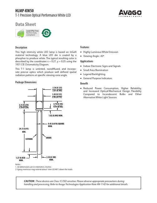
HLMP-KW50T-1 Precision Optical Performance White LEDData SheetPackage DimensionsNotes :1. All dimensions are in milimetres /inches.2. Epoxy meniscus may extend about 1mm (0.040”) down the leads.CAUTION : These devices are Class 1C ESD sensitive. Please observe appropriate precautions during handling and processing. Refer to Avago Technologies Application Note AN-1142 for additional details.NOM.DescriptionThis high intensity white LED lamp is based on InGaN material technology. A blue LED die is coated by a phosphor to produce white. The typical resulting color is described by the coordinates x = 0.27, y = 0.25 using the 1931 CIE Chromaticity Diagram.This T-1 lamp is untinted, nondiffused, and incorpo-rate precise optics which produce well defined spatial radiation patterns at specific viewing cone angle.Features• Highly Luminous White Emission • Viewing Angle : 45°Applications• Indoor Electronic Signs and Signals • Small Area Illumination • Legend Backlighting • General Purpose IndicatorsBenefit• Reduced Power Consumption, Higher Reliability, and Increased Optical/Mechanical Design Flexibility Compared to Incandescent Bulbs and Other Alternative White Light SourcesDevice Selection GuidePart Number Typical Viewing Angle Min Iv (mcd) @ 20mA Max Iv (mcd) @ 20mA Typical Chromaticity Coordinates (x,y)HLMP-KW50-QS00045°115025000.27, 0.25 Notes:1. The chromaticity coordinates are derived from the CIE 1931 Chromaticity Diagram and represent the perceived color of the device.2. θ1/2 is the off-axis angle where the luminous intensity is ½ the peak intensity.3. Tolerance for intensity bin limit is +/- 15%Absolute Maximum Ratings (T A = 25°C)Parameter Value UnitsDC Forward Current [1]30mAPeak Forward Current [2]100mAPower Dissipation111mWReverse Voltage (I R = 10μA)5VLED Junction Temperature110°COperating Temperature Range-40 to +85°CStorage Temperature Range-40 to +100°CNotes:1. Derate linearly as shown in Figure 5.2. Duty factor 10%, Frequency = 1KHz.Electrical Characteristics (T A = 25°C)Forward Voltage, V F (V) @ I F = 20 mA Reverse Breakdown,VR (V) @ I R = 10μACapacitance,C (pF), V F = 0,f = 1 MHzThermal ResistanceRθJ-PIN (°C/W)Typ.Max.Min.Typ.Typ.3.2 3.7570290WAVELENGTH –nmR E L A T I V E L U M I N O U S I N T E N S I T Y3807801.00.606805804800.40.80.201.50.3R E L A T I V E L U M I N O U S I N T EN S I T YFORWARD CURRENT -mA1.20.90.6-0.0100.02500.005-0.005Y -C O O R D I N A T E SX-COORDINATES(X,Y)VALUES @20mA REFERENCE TO (0,0)0.0150.0100.020F O R W A R D C U R R E N T -m A0FORWARD VOLTAGE -V2015353051025I F M A X .-M A X I M U M F O R W A R D C U R R E N T -m AT A -AMBIENT TEMPERATURE -C4080353010206010015255200302010Figure 1. Relative Intensity vs Wavelength Figure 2. Forward Current vs Forward VoltageFigure 3. Relative Iv vs. Forward Current Figure 4. Chromaticity shift vs. currentFigure 5. Maximum Fwd. Current vs TemperatureFigure 6. Spatial Radiation Pattern00.20.40.60.81.0SPATIAL DISPLACEMENT -DEG.R E L A T I V E I N T E N S I T YIntensity Bin Limits (mcd at 20 mA) Bin Min.Max.Q11501500R15001900S1******* Tolerance for each bin limit is ± 15%.Color Bin Limit TablesRank Limits(Chromaticity Coordinates)1xy0.3300.3600.3300.3180.3560.3510.3610.3852xy0.2870. 2950.2960.2760.3300.3180.3300.3393xy0.2640.2670.2800.2480.2960.2760.2830.3054 xy0.2830.3050.2870.2950.3300.3390.3300.360Tolerance for each color bin limit is ± 0.01Color Bin Limits with Respect to CIE 1931 Chromaticity Diagram0.260.30.340.38X-COORDINATEY-COORDINATENote:1. Bin categories are established for classification of products. Products may not be available in allbin categories. Please contact your Avago representative for information on currently availableRelative Light Output vs. Junction Temperature0.1110T J-JUNCTION TEMPERATURE-°CRELATIVELIGHTOUTPUT(NORMALIZEDATTJ=25ºC)InGaN DevicePrecautions:Lead Forming:• The leads of an LED lamp may be preformed or cut to length prior to insertion and soldering on PC board.• For better control, it is recommended to use proper tool to precisely form and cut the leads to applicable length rather than doing it manually.• If manual lead cutting is necessary, cut the leads after the soldering process. The solder connection forms a mechanical ground which prevents mechanical stress due to lead cutting from traveling into LED package. This is highly recommended for hand solder operation, as the excess lead length also acts as small heat sink.Soldering and Handling:• Care must be taken during PCB assembly and soldering process to prevent damage to the LED component. • LED component may be effectively hand soldered to PCB. However, it is only recommended under unavoidable circumstances such as rework. The closest manual soldering distance of the soldering heat source (soldering iron’s tip) to the body is 1.59mm. Soldering the LED using soldering iron tip closer than1.59mm might damage the LED.• ESD precaution must be properly applied on the soldering station and personnel to prevent ESD damage to the LED component that is ESD sensitive. Do refer to Avago application note AN 1142 for details. The soldering iron used should have grounded tip to ensure electrostatic charge is properly grounded.• Recommended soldering condition:WaveSoldering [1, 2]Manual Solder DippingPre-heat temperature 105 °C Max.-Preheat time 60 sec Max -Peak temperature 250 °C Max.260 °C Max.Dwell time3 sec Max.5 sec MaxNote:1) Above conditions refers to measurement with thermocouple mounted at the bottom of PCB.2) It is recommended to use only bottom preheaters in order to reduce thermal stress experienced by LED.• Wave soldering parameters must be set and maintained according to the recommended temperature and dwell time. Customer is advised to perform daily check on the soldering profile to ensure that it is always conforming to recommended soldering conditions.Note: Electrical connection between bottom surface of LED die and the lead frame is achieved through conductive paste.• Any alignment fixture that is being applied during wave soldering should be loosely fitted and should not apply weight or force on LED. Non metal material is recommended as it will absorb less heat during wave soldering process.• At elevated temperature, LED is more susceptible to mechanical stress. Therefore, PCB must allowed to cool down to room temperature prior to handling, which includes removal of alignment fixture or pallet.• If PCB board contains both through hole (TH) LED and other surface mount components, it is recommended that surface mount components be soldered on the top side of the PCB. If surface mount need to be on the bottom side, these components should be soldered using reflow soldering prior to insertion the TH LED.• Recommended PC board plated through holes (PTH) size for LED component leads.LED component lead sizeDiagonalPlated through hole diameter0.45 x 0.45 mm (0.018x 0.018 inch)0.636 mm (0.025 inch)0.98 to 1.08 mm (0.039 to 0.043 inch)0.50 x 0.50 mm (0.020x 0.020 inch)0.707 mm (0.028 inch)1.05 to 1.15 mm (0.041 to 0.045 inch)• Over-sizing the PTH can lead to twisted LED after clinching. On the other hand under sizing the PTH can cause difficulty inserting the TH LED.Note:1. PCB with different size and design (component density) will have different heat mass (heat capacity). This might cause a change in temperature experienced by the board if same wave soldering setting is used. So, it is recommended to re-calibrate the soldering profile again before loading a new type of PCB.2. Avago Technologies’ high brightness LED are using high efficiency LED die with single wire bond as shown below. Customer is advised to take extra precaution during wave soldering to ensure that the maximum wave temperature does not exceed 250°C and the solder contact time does not exceeding 3sec. Over-stressing the LED during soldering process might cause premature failure to the LED due to delamination.Avago Technologies LED configurationExample of Wave Soldering Temperature Profile for TH LED25020015050TIME (MINUTES)Recommended solder:Sn63(Leaded solder alloy)SAC305(Lead free solder alloy)Flux:Rosin fluxSolder bath temperature:245°C±5°C (maximum peak temperature =250°C)Dwell time:1.5sec -3.0sec (maximum =3sec)Note:Allow for board to be sufficiently cooled to room temperature before exerting mechanical force.T E M P E R A T U R E (°C )Packaging Box for Ammo PacksNote: For InGaN device, the ammo pack packaging box contains ESD logo.Packaging Label(i) Avago Mother Label: (Available on packaging box of ammo pack and shipping box)Acronyms and Definition:BIN:(i) Color bin only or VF bin only(Applicable for part number with color bins but without VF bin OR part number with VF bins and no color bin)OR(ii) Color bin incorporated with VF Bin(Applicable for part number that have both color bin and VF bin)(ii) Avago Baby Label (Only available on bulk packaging)Example:(i) Color bin only or VF bin only BIN: 2 (represent color bin 2 only) BIN: VB (represent VF bin “VB” only)(ii) Color bin incorporate with VF BinVB: VF bin “VB”2: Color bin 2 onlyDISCLAIMER: AVAGO’S PRODUCTS AND SOFTWARE ARE NOT SPECIFICALLY DESIGNED, MANUFAC-TURED OR AUTHORIZED FOR SALE AS PARTS, COMPONENTS OR ASSEMBLIES FOR THE PLANNING, CON-STRUCTION, MAINTENANCE OR DIRECT OPERATION OF A NUCLEAR FACILITY OR FOR USE IN MEDICAL DEVICES OR APPLICATIONS. CUSTOMER IS SOLELY RESPONSIBLE, AND WAIVES ALL RIGHTS TO MAKE CLAIMS AGAINST AVAGO OR ITS SUPPLIERS, FOR ALL LOSS, DAMAGE, EXPENSE OR LIABILITY IN CONNEC-TION WITH SUCH USE.For product information and a complete list of distributors, please go to our web site: Avago, Avago Technologies, and the A logo are trademarks of Avago Technologies Limited in the United States and other countries.Data subject to change. Copyright © 00 - 008 Avago Technologies Limited. All rights reserved. Obsoletes 989- 1 EN AV0 -0 EN - April 8, 008。
HLMP-K105-JM001中文资料
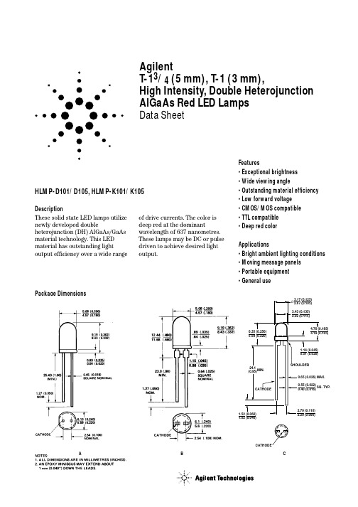
AgilentT-13/4 (5 mm), T-1 (3 mm),High Intensity, Double Heterojunction AlGaAs Red LED LampsData SheetHLMP-D101/D105, HLMP-K101/K105DescriptionThese solid state LED lamps utilize newly developed doubleheterojunction (DH) AlGaAs/GaAs material technology. This LED material has outstanding lightoutput efficiency over a wide rangeFeatures• Exceptional brightness • Wide viewing angle• Outstanding material efficiency • Low forward voltage • CMOS/MOS compatible • TTL compatible • Deep red colorApplications• Bright ambient lighting conditions • Moving message panels • Portable equipment • General useof drive currents. The color is deep red at the dominantwavelength of 637 nanometres.These lamps may be DC or pulse driven to achieve desired light output.Package DimensionsA B CSelection GuideLuminous IntensityIv (mcd) at 20 mA2θ1/2[1]Package Package Description Device HLMP-Min.Typ.Max.Degree Outline T-1 3/4 Red Tinted Diffused D10135.270.0–65AD101-J00xx35.270.0–65AD101-JK0xx35.270.0112.865AT-1 3/4 Red Untinted Non-diffused D105138.0240.0–24BD105-M00xx138.0240.0–24BD105-NO0xx200.0290.0580.024BT-1 Red Tinted Diffused K10122.045.0–60CK101-100xx22.045.0–60CK101-IJ0xx22.045.070.460CT-1 Red Untinted Non-diffused K10535.265.0–45CK105-J00xx35.265.0–45CK105-KL0xx56.4110.0180.445CNote:1. θ1/2 is the off axis angle from lamp centerline where the luminous intensity is 1/2 the on-axis value.Part Numbering SystemHLMP - x x xx - x x x xxMechanical Option00: Bulk01: Tape & Reel, Crimped Leads02: Tape & Reel, Straight LeadsA1: Right Angle Housing, Uneven Leads, T1A2: Right Angle Housing, Even Leads, T1B1: Right Angle Housing, Uneven Leads, T-1 3/4B2: Right Angle Housing, Even Leads, T-1 3/4DD, UQ: Ammo PackColor Bin Options0: Full Color Bin DistributionMaximum Iv Bin Options0: Open (no max. limit)Others: Please refer to the Iv Bin TableMinimum Iv Bin OptionsPlease refer to the Iv Bin TableLens Type01: Tinted, Diffused05: Untinted, NondiffusedColor Options1: AlGaAs RedPackage OptionsD: T-1 3/4K: T-1Absolute Maximum Ratings at T A = 25°CParameter ValuePeak Forward Current[1,2]300 mAAverage Forward Current[2]20 mADC Current[3]30 mAPower Dissipation87 mWReverse Voltage (I R = 100 µA) 5 VTransient Forward Current (10 µs Pulse)[4]500 mALED Junction Temperature110°COperating Temperature Range-20 to +100°C Storage Temperature Range-55 to +100°C Wave Soldering Temperature [1.59 mm (0.063 in.) from body]250°C for 3 seconds Lead Solder Dipping Temperature [1.59 mm (0.063 in.) from body]260°C for 5 seconds Notes:1.Maximum I PEAK at f = 1 kHz, DF = 6.7%.2.Refer to Figure 6 to establish pulsed operating conditions.3.Derate linearly as shown in Figure 5.4.The transient peak current is the maximum non-recurring peak current the device can withstand without damaging the LED die and wire bonds. It isnot recommended that the device be operated at peak currents beyond the Absolute Maximum Peak Forward Current.Electrical/Optical Characteristics at T A = 25°CSymbol Description Min.Typ.Max.Unit Test ConditionV F Forward Voltage 1.8 2.2V I F = 20 mAV R Reverse Breakdown Voltage 5.015.0V I R = 100 µAλp Peak Wavelength645nm Measurement at Peakλd Dominant Wavelength637nm Note 1∆λ1/2Spectral Line Halfwidth20nmτS Speed of Response30ns Exponential TimeConstant, e-t/T SC Capacitance30pF V F = 0, f = 1 MHzRθJ-PIN Thermal Resistance260[3]°C/W Junction to Cathode Lead210[4]290[5]ηV Luminous Efficacy80Im/W Note 2Notes:1.The dominant wavelength, λd, is derived from the CIE chromaticity diagram and represents the color of the device.2.The radiant intensity, I e, in watts per steradian, may be found from the equation I e = l V/ηV, where I V is the luminous intensity in candelas and ηV isluminous efficacy in lumens/watt.3.HLMP-D101.4.HLMP-D105.5.HLMP-K101/-K105.Figure 3. Relative luminous intensity vs. dc forward current.Figure 4. Relative efficiency vs. peak forward current.Figure 7. Relative luminous intensity vs. angular displacement. HLMP-D101.Figure 8. Relative luminous intensity vs. angular displacement. HLMP-K101.Intensity Bin LimitsIntensity Range (mcd)Color Bin Min.Max.Red I24.839.6J39.663.4K63.4101.5L101.5162.4M162.4234.6N234.6340.0O340.0540.0P540.0850.0Q850.01200.0R1200.01700.0S1700.02400.0T2400.03400.0U3400.04900.0V4900.07100.0W7100.010200.0X10200.014800.0Y14800.021400.0Z21400.030900.0Maximum tolerance for each bin limit is ± 18%.Mechanical Option MatrixMechanical Option Code Definition00Bulk Packaging, minimum increment 500 pcs/bag01Tape & Reel, crimped leads, minimum increment 1300 pcs (T-1 3/4)/1800 pcs (T-1) 02Tape & Reel, straight leads, minimum increment 1300 pcs (T-1 3/4)/1800 pcs (T-1) A1Right Angle Housing, uneven leads, minimum increment 500 pcs/bagA2Right Angle Housing, even leads, minimum increment 500 pcs/bagB1Right Angle Housing, uneven leads, minimum increment 500 pcs/bagB2Right Angle Housing, even leads, minimum increment 500 pcs/bagDD Ammo Pack, straight leads in 2K incrementUQ Ammo Pack, horizontal leads in 2K incrementNote:All categories are established for classification of products. Products may not be available in all categories. Please contact your local Agilent representative for further clarification/information./semiconductors For product information and a complete list of distributors, please go to our web site.For technical assistance call:Americas/Canada: +1 (800) 235-0312 or (916) 788-6763Europe: +49 (0) 6441 92460China: 10800 650 0017Hong Kong: (+65) 6756 2394India, Australia, New Zealand: (+65) 6755 1939 Japan: (+81 3) 3335-8152 (Domestic/Interna-tional), or 0120-61-1280 (Domestic Only) Korea: (+65) 6755 1989Singapore, Malaysia, Vietnam, Thailand, Philippines, Indonesia: (+65) 6755 2044 Taiwan: (+65) 6755 1843Data subject to change.Copyright © 2004 Agilent Technologies, Inc. Obsoletes 5968-1440ENovember 12, 20045988-2230EN。
科佩斯-HYDROMAT 1000 1300 1700 2000型号剪切机说明书

EASE OF MAINTENANCE AND OPTIMIZED COSTSThe machine is delivered with an ideal ergonomic maintenance platform and special tools for quick and safe blade changes. Through the screwless lower blade tightening system specifically developed by Copex, the time required to replace blades is only 2 hours with2 operators.OPERATION CONTROLThe intuitive touch screen displayingall production parameters and operatingdata can be used to carry out preventivetests and manage alarms. An additionalportable screen can be positioned inthe loading crane. Remote maintenanceallows Copex to take actions remotelyat the operator’s request. A FAST SHEAR The shear makes 7 cuts per minute thanks to the simultaneous movements of the shear and the hold-down. Equipped with a rail breaker , it processes the hardest scrap. A hydraulic balancing valve system regulates the downward movement of the shear using maximum power while controlling the movement perfectly. In case of sudden material breakage, a counter-pressure compensates the own load of the blade slide block while its extended guide system reduces the clearance between the blades and guarantees constant cutting performance .ENERGY EFFICIENCYHigh cutting speeds are made possible bythe simultaneous automatic movementsof the hold-down, the shear, the side-press, the lid and the preload table.The speed of the movements is increasedby the transfer of oil between the cylindersand the use of new generation high pressure pumps . While cycle times are optimized, energy consumption is reduced by 17% in comparison to previous generations of scrap shears. In addition, the proportional design of the hydraulic pumps means increasedenergy efficiency during certain operating phases.Lidex scrap shears are ideal for processing heavy and bulkymetal scrap or when high production volumes are required .They are the only side compression machines to offer a true fullyautomatic cycle that includes the discharging of scrap materialsfrom the preload table into the compression box, the closing of thebox and the complete cutting cycle.PATENTED HIGH COMPACTION EFFECTIVENESS Copex offers the Lidex as the only machine having a fully automatic and extremely fast closing cycle of the compression box , particularly through two major patented innovations. Firstly, due to the kinematics of the preload table with its offset axis, the falling scrap is directed directly to the pusher area exactly below the lid. In addition, the high amplitude lid covering 80% of the boxin closed position, has a large lever arm making it very powerful. The preload table is loaded in hidden time during the box closing and shearing cycles, which further reduces cycle times.SERIESThe latest Copex scrap shears type S-Wing are the response to thesustained demand for machines with pre-compression by wings forprocessing light to medium-heavy bulky scrap . These machineshave a reinforced compression box and optimal cylinder protection.The compression box allows for high compaction performance dueto the overstroke of the two press wings. S-Wing machines have anextended blade slide block guide system and the same clever deviceas the heavy-duty scrap shears with side compression for quick bladereplacement. The S-Wing machine series is a concentrate ofCopex know-how . A HIGH-PERFORMANCE SHEARThrough the simultaneous movements ofthe shear and the hold-down, the machine achieves very high cutting speeds . The 1000t cutting force version is equippedwith a rail breaker for processing thehardest scrap. The extra-long slide blockguiding design ensures consistent cuttingperformance under heavy use. The bladeclearance adjustment device helps toincrease the service life of the machineand reduce energy consumption.HIGH COMPRESSION EFFICIENCY The reinforced press wings box is covered with easily replaceable anti-abrasion wear plates. T o increase compaction power andreduce cycle times, the press wings have a specific kinematics for optimal "wrapping" during the compression phase. Each press wing has a large overstroke to reduce the wear of the plates duringthe forward movement of the pusher, contributing to improve thecompaction efficiency. The preload table increases productionas scrap materials are loaded in hidden time.DURABILITY AND LONGEVITYThe pusher cylinder rod is coveredalong its entire length for optimalprotection. The wear plates of thepusher piston and the bottom ofthe compression box, as well asthose of the hold-down chamber,are grooved, preventing any scrapmetal from passing through. Allhydraulic connections, electricalwiring and sensitive componentssuch as magnetostrictive and lasersensors are protected against shocks and scrap .OPERATING COMFORTThrough the display screen of the radio control, the operator visualizes all operating data at a single glance. Through the additional screen on the switch cabinet the operator manages operating data and anticipates maintenance. The electrical and hydraulic units, placed in a soundproof container , are easily accessible for maintenance. S-Wing machines also have their own maintenance platform and special tools for safe and easy replacement of the cutting blades.SERIESReflex mobile and portable scrap shears have been designed to processlight bulky scrap metal . These machines are very easy to move andinstall. T hey are available either with road approved chassis in true mobileversion, or portable with hydraulic support legs. They can also be fittedon a metallic frame. T hrough the extended slide block guide systemon the cutting head , Reflex machines offer unequalled qualities of robustness and durability for this category of machine .PORTABLE VERSIONReflex scrap shears can be supplied in aportable version with or without hydraulicsupport legs, making it possible to loadthem onto a low bed trailer.HIGH EASE OF OPERATIONReflex machines have excellent soundproofing thanksto the use of high quality insulating materials covering theengine casing and large acoustic louvres that considerablyreduce the engine noise level.Accessibility to parts and control elements is optimisedby large removable panels and a platform designed tofacilitate the operator’s movements.WHEEL PROTECTION SYSTEM The wheel protection system consists of high-strength steel plates and is a real advantage for mobile shears. During transport, the plates are in the raised position for safe movement of the machine. On the scrap yard, they are folded down to protect the road axles from falling scrap. SHEAR FRAME: ROBUSTNESS AND DURABILITY The Reflex is the first mobile shear in the market to feature the same techniques as those used on heavy-duty shears. Theinnovative shear guiding system ensures abalanced distribution of the cutting forces.The first advantage is the extremelylong service life of the shear frame. Anadditional asset is the reduced wear ofthe consumables that makes it possible tomaintain a high cutting performance overtime with a frequency of interventions divided by 3.COMPRESSION EFFICIENCY The innovative kinematics of the press wings developed by Copex maximises the forces at the end of the box closing, where it is most necessary, while the design of the press wings offers optimal wrapping of the scrap material during the pressing phase. As a result, cycles times are significantly reduced. The Reflex 900 has the most powerful box closing force of any other machine of this class.SERIESFactoryZ.I. KerpontB.P . 6032856603 Lanester CedexFranceTel. +33 (0)2 97 76 26 44Fax +33 (0)2 97 76 34 12*****************Head Office 109, rue Cardinet 75017 Paris France T+74 YEARS OF EXPERIENCE +900 MACHINES IN THE WORLD +100 WORKERS +40 COUNTRIES。
推荐-石油天然气行业设备分类与编码第四版 精品
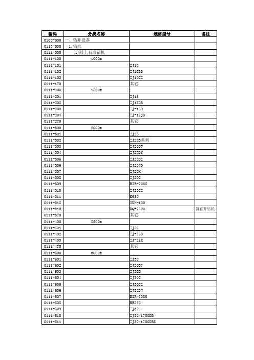
分类名称 其它
(2)气体钻井配套装置 空压机
增压机
制氮设备 雾化泵
(3)欠平衡钻井装置 不压井起下钻装置 液气分离器
旋转防喷器
节流管汇
SRG 其它
其它
规格型号
1150XHDLQ SULLAIR 1150/350 XRS415 XRVS455 XRVS976 其它
6T-855-62-2160 E3430 FKY450 FY400 其它
C-I-Ⅱ E1700 ZJ50D ZJ50DB ZJ50DF ZJ50J ZJ50JD ZJ50L ZJ50LZPD ZJ50LDB ZJ50DBS-J 其它
ZJ-60L F320-3DH F320-4DH 其它
ZJ70D ZJ70DB ZJ70DBF ZJ70DBS
备注 快速移动 拖挂钻机
皮带钻机
分类名称 (4)地面流程测试装置 (5)顶部驱动装置
2250kN-3150kN 3150kN-4500kN 4500kN及以上
(6)井控装置
3.钻机配套设备 (1)井架
(2)底座
70MPa 105MPa 其它
规格型号
TDS-10SA DQ-60D1 其它
TDS-9S DQ60P 其它
1050E DQ70DBS DQ-7500 TDS-11S TDS-11SA TESCO-500 其它
单闸板系列 双闸板系列 环形系列 剪切闸板系列 控制系统 其它
JJ165 JJ170/41-K JJ225系列 JJ250系列 JJ315系列 JJ450系列 JJ90系列 JJ100 TJ300/43A 其它
DZ170系列 DZ225系列 DZ250系列 DZ315系列 DZ450系列
备注
HLMP-CM26-S0A00中文资料
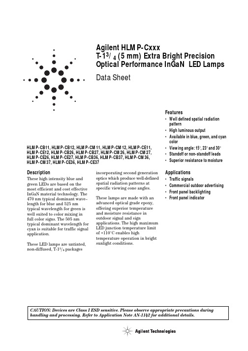
Agilent HLMP-CxxxT-13/4 (5mm) Extra Bright Precision Optical Performance InGaN LED Lamps Data SheetDescriptionThese high intensity blue and green LEDs are based on the most efficient and cost effective InGaN material technology. The 470 nm typical dominant wave–length for blue and 525 nm typical wavelength for green is well suited to color mixing in full color signs. The 505 nm typical dominant wavelength for cyan is suitable for traffic signal application.These LED lamps are untinted, non-diffused, T-13/4 packagesFeatures•Well defined spatial radiationpattern•High luminous output•Available in blue, green, and cyancolor•Viewing angle: 15°, 23°and 30°•Standoff or non-standoff leads•Superior resistance to moistureApplications•Traffic signals•Commercial outdoor advertising•Front panel backlighting•Front panel indicator incorporating second generationoptics which produce well-definedspatial radiation patterns atspecific viewing cone angles.These lamps are made with anadvanced optical grade epoxy,offering superior temperatureand moisture resistance inoutdoor signal and signapplications. The high maximumLED junction temperature limitof +110°C enables hightemperature operation in brightsunlight conditions.HLMP-CB11, HLMP-CB12, HLMP-CM11, HLMP-CM12, HLMP-CE11,HLMP-CE12, HLMP-CB26, HLMP-CB27, HLMP-CM26, HLMP-CM27,HLMP-CE26, HLMP-CE27, HLMP-CB36, HLMP-CB37, HLMP-CM36,HLMP-CM37, HLMP-CE36, HLMP-CE37CAUTION: Devices are Class I ESD sensitive. Please observe appropriate precautions during handling and processing. Refer to Application Note AN-1142 for additional details.Package DimensionsPackage APackage B5.80 ± 0.20(0.228 ±∅ CATHODEFLATMIN.SQ. TYP.NOTES:1. MEASURED JUST ABOVE FLANGE.2. ALL DIMENSIONS ARE IN MILLIMETERS (INCHES).3. EPOXY MENISCUS MAY EXTEND ABOUT 1 mm (0.040") DOWN THE LEADS.4. IF HEAT SINKING APPLICATION IS REQUIRED, THE TERMINAL FOR HEAT SINK IS ANODE.Device Selection GuideTypicalViewing Angle,Intensity (cd) at 20 mA PackagePart Number Color2q1/2 (Degree)Min.Max.Standoff Dimension Lens HLMP-CB11-TW0xx Blue15 2.57.2No A Clear HLMP-CB11-UVAxx Blue15 3.2 5.5No A Clear HLMP-CB12-TW0xx Blue15 2.57.2Yes B Clear HLMP-CM11-Y20xx Green159.327.0No A Clear HLMP-CM11-Z1Cxx Green1512.021.0No A Clear HLMP-CM12-Y20xx Green159.327.0Yes B Clear HLMP-CE11-X10xx Cyan157.221.0No A Clear HLMP-CE12-X10xx Cyan157.221.0Yes B Clear HLMP-CB26-SV0xx Blue23 1.9 5.5No A Clear HLMP-CB26-TUDxx Blue23 2.5 4.2No A Clear HLMP-CB27-SV0xx Blue23 1.9 5.5Yes B Clear HLMP-CM26-X10xx Green237.221.0No A Clear HLMP-CM26-YZCxx Green239.316.0No A Clear HLMP-CM27-X10xx Green237.221.0Yes B Clear HLMP-CE26-WZ0xx Cyan23 5.516.0No A Clear HLMP-CE27-WZ0xx Cyan23 5.516.0Yes B Clear HLMP-CB36-QT0xx Blue30 1.15 3.2No A Clear HLMP-CB36-RSAxx Blue30 1.5 2.5No A Clear HLMP-CB37-RU0xx Blue30 1.5 4.2Yes B Clear HLMP-CB37-RSDxx Blue30 1.5 2.5Yes B Clear HLMP-CM36-X10xx Green307.221.0No A Clear HLMP-CM36-XYCxx Green307.212.0No A Clear HLMP-CM37-X10xx Green307.221.0Yes B Clear HLMP-CM37-XYCxx Green307.212.0Yes B Clear HLMP-CM37-XYDxx Green307.212.0Yes B Clear HLMP-CE36-WZ0xx Cyan30 5.516.0No A Clear HLMP-CE37-WZ0xx Cyan30 5.516.0Yes B ClearNotes:1.Tolerance for luminous intensity measurement is ±15%.2.The luminous intensity is measured on the mechanical axis of the lamp package.3.The optical axis is closely aligned with the package mechanical axis.4.LED light output is bright enough to cause injuries to the eyes. Precautions must be taken to prevent looking directly at the LED without propersafety equipment.5. 2q1/2 is the off-axis angle where the luminous intensity is 1/2 the on-axis intensity.Part Numbering SystemHLMP-x x xx-x x x xxMechanical Options00: BulkDD: Ammo PackColor Bin Options0: Full Color Bin DistributionA: Color Bin 1 and 2C: Color Bin 3 and 4D: Color Bin 4 and 5Maximum Intensity Bin0: No Maximum Intensity Bin LimitationOthers: Refer to Device Selection GuideMinimum Intensity BinRefer to Device Selection GuideViewing Intensity Bin11: 15° Without Standoff12: 15°With Standoff26: 23°Without Standoff27: 23°With Standoff36: 30°Without standoff37: 30°With StandoffColorB: Blue 470 nmM: Green 525 nmE: Cyan 505 nmPackageC: T-13/4 (5 mm) Round LampAbsolute Maximum Rating at T A = 25°CParameters Value UnitDC Forward Current [1]30mAPeak Pulsed Forward Current[3]100mAAverage Forward Current30mAPower Dissipation120mWLED Junction Temperature110°COperating Temperature Range–40 to +85°CStorage Temperature Range–40 to +100°CWave Soldering Temperature[2]250 for 3 secs°CNotes:1.Derate linearly as shown in Figure2.2.1.59 mm (0.060 inch) below body.3.Duty factor 10%, frequency 1 KHz.Electrical/Optical CharacteristicsT A = 25o CBlue Green CyanParameters Symbol Min.Typ.Max.Min.Typ.Max.Min.Typ.Max.Units Test Condition Forward Voltage V F 3.5 4.0 3.6 4.0 3.5 4.0V I F = 20 mA Reverse Voltage[1]V R 5.0 5.0 5.0V I R = 10 µA Thermal Resistance R q J-PIN240240240o C/W LED Junction toAnode Lead Dominant l d460470480520525540490505510nm I F = 20 mA Wavelength[2]Peak Wavelength l PEAK464516501nm Peak of Wavelengthof Spectral Distribu-tion at I F = 20 mA Spectral Half Width Dl1/2233230nm Wavelength Widthat Spectral Distribu-tion Power Pointat I F = 20 mA Luminous Efficacy[3]h v74484319lm/W Emitted LuminousPower/EmittedRadiant Power Notes:1.The reverse voltage of the product is equivalent to the forward voltage of the protective chip at I R = 10 µA.2.The dominant wavelength, l d, is derived from the Chromaticity Diagram and represents the color of the lamp.3.The radiant intensity, Ie in watts/steradian, may be found from the equation Ie = Iv/h v, where Iv is the luminous intensity in candelas and h v is theluminous efficacy in lumens/watt.Figure 5. Relative intensity vs. DC forward current.Figure 4. Relative dominant wavelength vs. DC forward current.DC FORWARD CURRENT – mAR E L A T I V E D O M I N A N T W A V E L E N G T H (N O R M A L I Z E D A T 20 m A )1020301.0250.9901.0151.0201.0101.0051.0000.995GREENBLUER E L A T I V E I N T E N S I T Y (N O R M A L I Z E D A T 20 m A )FORWARD CURRENT – mAFigure 1. Relative intensity vs. wavelength.Figure 3. Forward current vs. forward voltage.Figure 2. Forward current vs. ambient temperature.WAVELENGTH – nmR E L A T I V E I N T E N S I T Y1.0000.800.600.400.20030103.0202.01.0F O R W A R D C U R R E N T – m AFORWARD VOLTAGE – V 4.0CYANGREENBLUEI F – F O R W A R D C U R R E N T – m AV F – FORWARD VOLTAGE – VOLTSFigure 6. Spatial radiation pattern for Cx11 and Cx12.R E L A T I V E L U M I N O U S I N T E N S I T Y10ANGULAR DISPLACEMENT – DEGREES0.5-90-600-30306090Figure 7. Spatial radiation pattern for Cx26 and Cx27.Figure 8. Spatial radiation pattern for Cx36 and Cx37.R E L A T I V E L U M I N O U S I N T E N S I T Y10ANGULAR DISPLACEMENT – DEGREES0.5-90-600-30306090R E L A T I V E L U M I N O U S I N T E N S I T Y10ANGULAR DISPLACEMENT – DEGREES0.5-90-600-30306090Intensity Bin Limit TableIntensity (mcd) at 20 mA Bin Min MaxN680880P8801150Q11501500R15001900S1*******T25003200U32004200V42005500W55007200X72009300Y930012000Z1200016000 11600021000 Tolerance for each bin limit is ±15%.Blue Color Bin TableBin Min Dom Max Dom Xmin Ymin Xmax Ymax 1460.0464.00.14400.02970.17660.09660.18180.09040.13740.0374 2464.0468.00.13740.03740.16990.10620.17660.09660.12910.0495 3468.0472.00.12910.04950.16160.12090.16990.10620.11870.0671 4472.0476.00.11870.06710.15170.14230.16160.12090.10630.0945 5476.0480.00.10630.09450.13970.17280.15170.14230.09130.1327 Tolerance for each bin limit is ±0.5 nm.Cyan Color Bin TableBin Min Dom Max Dom Xmin Ymin Xmax Ymax 1490.0495.00.04540.29450.11640.38890.13180.3060.02350.4127 2495.0500.00.03450.41270.10570.47690.11640.38890.00820.5384 3500.0505.00.00820.53840.10270.55840.10570.47690.00390.6548 4505.0510.00.00390.65480.10970.62510.10270.55840.01390.7502 7498.0503.00.01320.48820.10280.52730.10920.44170.00400.6104 8503.0508.00.00400.61040.10560.60070.10280.52730.00800.7153 Tolerance for each bin limit is ±0.5 nm.Green Color Bin TableBin Min Dom Max Dom Xmin Ymin Xmax Ymax 1520.0524.00.07430.83380.18560.65560.16500.65860.10600.8292 2524.0528.00.10600.82920.20680.64630.18560.65560.13870.8148 3528.0532.00.13870.81480.22730.63440.20680.64630.17020.7965 4532.0536.00.17020.79650.24690.62130.22730.63440.20030.7764 5536.0540.00.20030.77640.26590.60700.24690.62130.22960.7543 Tolerance for each bin limit is ±0.5 nm./semiconductors For product information and a complete list of distributors, please go to our web site.For technical assistance call:Americas/Canada: +1 (800) 235-0312 or (916) 788-6763Europe: +49 (0) 6441 92460China: 10800 650 0017Hong Kong: (+65) 6756 2394India, Australia, New Zealand: (+65) 6755 1939 Japan: (+81 3) 3335-8152(Domestic/Interna-tional), or 0120-61-1280(Domestic Only) Korea: (+65) 6755 1989Singapore, Malaysia, Vietnam, Thailand, Philippines, Indonesia: (+65) 6755 2044 Taiwan: (+65) 6755 1843Data subject to change.Copyright © 2004 Agilent Technologies, Inc. December 7, 20045989-1022EN。
HLMP-EH32-MQ000中文资料
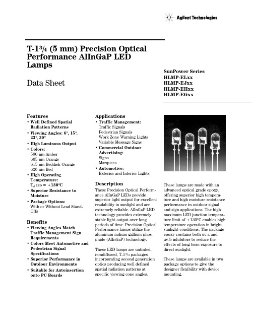
T-13/4 (5 mm) Precision Optical Performance AlInGaP LED LampsData SheetFeatures• Well Defined Spatial Radiation Patterns• Viewing Angles: 6°, 15°, 23°, 30°• High Luminous Output• Colors:590 nm Amber605 nm Orange615 nm Reddish-Orange626 nm Red• High Operating Temperature:T J LED=+130°C• Superior Resistance to Moisture• Package Options:With or Without Lead Stand-OffsBenefits• Viewing Angles Match Traffic Management Sign Requirements• Colors Meet Automotive and Pedestrian Signal Specifications• Superior Performance in Outdoor Environments• Suitable for Autoinsertion onto PC Boards Applications• Traffic Management:Traffic SignalsPedestrian SignalsWork Zone Warning LightsVariable Message Signs• Commercial OutdoorAdvertising:SignsMarquees• Automotive:Exterior and Interior LightsDescriptionThese Precision Optical Perform-ance AlInGaP LEDs providesuperior light output for excellentreadability in sunlight and areextremely reliable. AlInGaP LEDtechnology provides extremelystable light output over longperiods of time. Precision OpticalPerformance lamps utilize thealuminum indium gallium phos-phide (AlInGaP) technology.These LED lamps are untinted,nondiffused, T-13/4 packagesincorporating second generationoptics producing well definedspatial radiation patterns atspecific viewing cone angles.SunPower SeriesHLMP-ELxxHLMP-EJxxHLMP-EHxxHLMP-EGxxThese lamps are made with anadvanced optical grade epoxy,offering superior high tempera-ture and high moisture resistanceperformance in outdoor signaland sign applications. The highmaximum LED junction tempera-ture limit of +130°C enables hightemperature operation in brightsunlight conditions. The packageepoxy contains both uv-a anduv-b inhibitors to reduce theeffects of long term exposure todirect sunlight.These lamps are available in twopackage options to give thedesigner flexibility with devicemounting.Device Selection GuideTypicalViewing Color and Luminous Angle Dominant Lamps Without Standoffs Lamps With Standoffs Intensity Iv (mcd) [1,2] 2θ1/2Wavelength on Leads on Leads@ 20 mA (Deg.)[4](nm), Typ.[3] (Outline Drawing A)(Outline Drawing B)Min.Max.HLMP-EL08-VY000HLMP-EL10-VY000360013800HLMP-EL08-VYK00*360013800HLMP-EL08-VXK00*360010700HLMP-EL08-VX400**360010700HLMP-EL08-VX000360010700HLMP-EL08-WZ000HLMP-EL10-WZ000470018400HLMP-EL08-XZ400**620018400 Amber 590HLMP-EL08-XZ000620018400HLMP-EL08-XZK00*620018400HLMP-EL08-XY000620013800HLMP-EL08-XYK00*620013800HLMP-EL08-X1K00*620024100HLMP-EL08-X1000HLMP-EL10-X1000620024100 6°[5]HLMP-EJ08-WZ000HLMP-EJ10-WZ000470018400 Orange 605HLMP-EJ08-X1000HLMP-EJ10-X1000620024100HLMP-EJ08-Y2000HLMP-EJ10-Y2000800031000HLMP-EH08-UX000HLMP-EH10-UX000275010700HLMP-EH08-VY000HLMP-EH10-VY000360013800 Red-Orange 615HLMP-EH08-WZ000HLMP-EH10-WZ000470018400HLMP-EH08-X1000HLMP-EH10-X1000620024100HLMP-EH08-Y2000HLMP-EH10-Y2000800031000HLMP-EG08-VW00036008300HLMP-EG08-VY000HLMP-EG10-VY000360013800HLMP-EG08-WZ000HLMP-EG10-WZ000470018400 Red 626HLMP-EG08-X1000HLMP-EG10-X1000620024100HLMP-EG08-YZ000800018400HLMP-EG08-Y1000800024100HLMP-EG08-Y2000HLMP-EG10-Y2000800031000 Notes:1. The luminous intensity is measured on the mechanical axis of the lamp package.2.The optical axis is closely aligned with the package mechanical axis.3. The dominant wavelength, λd, is derived from the CIE Chromaticity Diagram and represents the color of the lamp.4. θ1/2 is the off-axis angle where the luminous intensity is one half the on-axis intensity.5.The intensity of narrow viewing angle lamps is measured at the intensity peak.Part numbers in bold are recommended for new designs.*HLMP-xLxx-xxK00 are selected to amber color bins 2 and 4 only.Device Selection Guide (Continued)TypicalViewing Color and Luminous Angle Dominant Lamps Without Standoffs Lamps With Standoffs Intensity Iv (mcd) [1,2] 2θ1/2Wavelength on Leads on Leads@ 20 mA (Deg.)[4](nm), Typ.[3] (Outline Drawing A)(Outline Drawing B)Min.Max.HLMP-EL15-PS000HLMP-EL17-PS0007652900HLMP-EL15-QR00010002200HLMP-EL15-QRK00*10002200HLMP-EL15-QS00010002900 Amber 590HLMP-EL15-QS400**10002900HLMP-EL15-QSK00*10002900HLMP-EL15-QT000HLMP-EL17-QT00010003700 15°HLMP-EL15-QTK00*10003700HLMP-EL15-RU000HLMP-EL17-RU00013004800HLMP-EJ15-PS0007652900 Orange 605HLMP-EJ15-RU000HLMP-EJ17-RU00013004800HLMP-EJ15-SV000HLMP-EJ17-SV00016506300 Red-Orange 615HLMP-EH15-QT000HLMP-EH17-QT00010003700HLMP-EH15-RU000HLMP-EH17-RU00013004800HLMP-EG15-PS0007652900 Red 626HLMP-EG15-QT000HLMP-EG17-QT00010003700HLMP-EG15-RU000HLMP-EG17-RU00013004800HLMP-EL24-MQ0004501730HLMP-EL24-NR000HLMP-EL26-NR0005902200HLMP-EL24-PS000HLMP-EL26-PS0007652900HLMP-EL24-PSK00*7652900HLMP-EL24-PR400**7652200HLMP-EL24-PQK00*7651730 Amber 590HLMP-EL24-QR00010002200HLMP-EL24-QRK00*10002200 23°HLMP-EL24-QS00010002900HLMP-EL24-QSK00*10002900HLMP-EL24-QS400**10002900HLMP-EL24-QT000HLMP-EL26-QT00010003700HLMP-EL24-QTK00*10003700 Notes:1. The luminous intensity is measured on the mechanical axis of the lamp package.2.The optical axis is closely aligned with the package mechanical axis.3. The dominant wavelength, λd, is derived from the CIE Chromaticity Diagram and represents the color of the lamp.4. θ1/2 is the off-axis angle where the luminous intensity is one half the on-axis intensity.5.The intensity of narrow viewing angle lamps is measured at the intensity peak.Device Selection Guide (Continued)TypicalViewing Color and Luminous Angle Dominant Lamps Without Standoffs Lamps With Standoffs Intensity Iv (mcd) [1,2] 2θ1/2Wavelength on Leads on Leads@ 20 mA (Deg.)[4](nm), Typ.[3] (Outline Drawing A)(Outline Drawing B)Min.Max.Orange 605HLMP-EJ24-QT000HLMP-EJ26-QT00010003700HLMP-EJ24-RU000HLMP-EJ26-RU00013004800HLMP-EH26-PS0007652900 Red-Orange 615HLMP-EH24-QT000HLMP-EH26-QT00010003700 23ºHLMP-EH24-RU000HLMP-EH26-RU00013004800HLMP-EG24-PS000HLMP-EG26-PS0007652900 Red 626HLMP-EG24-QT000HLMP-EG26-QT00010003700HLMP-EG24-RU000HLMP-EG26-RU00013004800HLMP-EL30-MQ000HLMP-EL32-MQ0004501730HLMP-EL30-NR000HLMP-EL32-NR0005902200HLMP-EL30-PQ0007651730HLMP-EL30-PQK00*7651730 Amber 590HLMP-EL30-PR0007652200HLMP-EL30-PR400**7652200HLMP-EL30-PRK00*7652200HLMP-EL30-PS000HLMP-EL32-PS0007652900HLMP-EL30-PSK00*7652900 30°HLMP-EJ30-MQ0004501730 Orange 605HLMP-EJ30-NR000HLMP-EJ32-NR0005902200HLMP-EJ30-PS000HLMP-EJ32-PS0007652900HLMP-EH30-MQ000HLMP-EH32-MQ0004501730 Red-Orange 615HLMP-EH30-NR000HLMP-EH32-NR0005902200HLMP-EH30-PS000HLMP-EH32-PS0007652900HLMP-EG30-KN0002701010HLMP-EG30-MQ000HLMP-EG32-MQ0004501730HLMP-EG30-NQ0005901730HLMP-EG30-NR000HLMP-EG32-NR0005902200 Red 626HLMP-EG30-PQ0007651730HLMP-EG30-PR0007652200HLMP-EG30-PS000HLMP-EG32-PS0007652900 Notes:1. The luminous intensity is measured on the mechanical axis of the lamp package.2.The optical axis is closely aligned with the package mechanical axis.3. The dominant wavelength, λd, is derived from the CIE Chromaticity Diagram and represents the color of the lamp.4. θ1/2 is the off-axis angle where the luminous intensity is one half the on-axis intensity.5.The intensity of narrow viewing angle lamps is measured at the intensity peak.Part Numbering SystemHLMP-x x xx-x x x xxMechanical Options00: Bulk PackagingDD: Ammo PackYY: Flexi-Bin; Bulk PackagingZZ: Flexi-Bin; Ammo PackColor Bin Selections0: No color bin limitation4: Amber color bin 4 onlyK: Amber color bins 2 and 4 onlyMaximum Intensity Bin0: No Iv bin limitationMinimum Intensity BinViewing Angle & Lead Stand Offs08: 6 deg without lead stand offs10: 6 deg with lead stand offs15: 15 deg without lead stand offs17: 15 deg with lead stand offs24: 23 deg without lead stand offs26: 23 deg with lead stand offs30: 30 deg without lead stand offs32: 30 deg with lead stand offsColorG: 626 nm RedH: 615 nm Red-OrangeJ: 605 nm OrangeL: 590 nm AmberPackageE: 5 mm RoundNOTES:1. ALL DIMENSIONS ARE IN MILLIMETERS (INCHES).2. LEADS ARE MILD STEEL, SOLDER DIPPED.3. TAPERS SHOWN AT TOP OF LEADS (BOTTOM OF LAMP PACKAGE) INDICATE AN EPOXY MENISCUS THAT MAY EXTEND ABOUT 1 mm (0.040 in.) DOWN THE LEADS.4. RECOMMENDED PC BOARD HOLE DIAMETERS:• LAMP PACKAGE A WITHOUT STAND-OFFS: FLUSH MOUNTING AT BASE OF LAMP PACKAGE = 1.143/1.067 (0.044/0.042).• LAMP PACKAGE B WITH STAND-OFFS: MOUNTING AT LEAD STAND-OFFS = 0.965/0.889 (0.038/0.035).5. FOR DOME HEIGHTS ABOVE LEAD STAND-OFF SEATING PLANE, d, LAMP PACKAGE B, SEE TABLE.BPackage DimensionsA(0.039)(0.039)PART NO.d HLMP-XX1012.37 ± 0.25 (0.487 ± 0.010)HLMP-XX1712.42 ± 0.25 (0.489 ± 0.010)HLMP-XX2612.52 ± 0.25 (0.493 ± 0.010)HLMP-XX3211.96 ± 0.25 (0.471 ± 0.010)Electrical/Optical Characteristics at T A = 25°CParameter SymbolMin.Typ.Max.UnitsTest Conditions Forward VoltageI F = 20 mAAmber (λd = 590 nm) 2.02Orange (λd = 605 nm)V F 1.98 2.4VRed-Orange (λd = 615 nm) 1.94Red (λd = 626 nm) 1.90Reverse Voltage V R 520VI F = 100 µAPeak Wavelength:Peak of Wavelength of Amber (λd = 590 nm)592Spectral Distribution Orange (λd = 605 nm)λPEAK 609nmat I F = 20 mARed-Orange (λd = 615 nm)621Red (λd = 626 nm)635Spectral Halfwidth∆λ1/217nmWavelength Width at Spectral Distribution 1/2 Power Point at I F = 20 mASpeed of Response τs 20ns Exponential Time Constant, e -t/τCapacitanceC 40pF V F = 0, f = 1 MHzThermal Resistance R θJ-PIN240°C/WLED Junction-to-Cathode LeadLuminous Efficacy [1]Emitted LuminousAmber (λd = 590 nm)480Power/Emitted Radiant Orange (λd = 605 nm)ηv370lm/WPowerRed-Orange (λd = 615 nm)260Red (λd = 626 nm)150Note:Absolute Maximum Ratings at T A = 25°CDC Forward Current [1,2,3]............................................................50 mA Peak Pulsed Forward Current [2,3]..............................................100 mA Average Forward Current [3].........................................................30 mA Reverse Voltage (I R = 100 µA).........................................................5 V LED Junction Temperature..........................................................130°C Operating Temperature ..............................................-40°C to +100°C Storage Temperature ..................................................-40°C to +120°C Dip/Drag Soldering Temperature...........................260°C for 6 seconds Through-the-Wave Preheat Temperature......................................145°C Through-the-Wave Solder Temperature.................245°C for 3 seconds [1.59 mm (0.060 in.) below seating plane]Notes:1. Derate linearly as shown in Figure 4.2. For long term performance with minimal light output degradation, drive currentsbetween 10 mA and 30 mA are recommended. For more information on recommended drive conditions, please refer to Application Brief I-024 (5966-3087E).3. Operating at currents below 1 mA is not recommended. Please contact your local representative for further information.sFigure 2. Forward Current vs.Forward Voltage.Figure 3. Relative Luminous Intensity vs. Forward Current.Figure 4. Maximum Forward Current vs. Ambient Temperature. Derating Based on T JMAX = 130°C.Figure 1. Relative Intensity vs. Peak Wavelength.I F – F O R W A R D C U R R E N T – m AT A – AMBIENT TEMPERATURE – °CR E L A T I V E I N T E N S I T Y – %1000θ – ANGULAR DISPLACEMENT – DEGREES8060507020-20-15103040-1051015202590-25-5WAVELENGTH – nmR E L A T I V E I N T E N S I T YR E L A T I V E L U M I N O U S I N T E N S I T Y (N O R M A L I Z E D A T 20 m A )00I F – DC FORWARD CURRENT – mA 403.02.01.51.00.520602.5C U R R E NT – m AV F – FORWARD VOLTAGE – VBin Name Min.Max.K 310400L 400520M 520680N680880P 8801150Q 11501500R 15001900S 19002500T 25003200U 32004200V 42005500W 55007200X 72009300Y 930012000Z 12000160001160002100022100027000Intensity Bin Limits (mcd at 20 mA)Tolerance for each bin limit is ± 15%.Bin Name Min.Max.1584.5587.02587.0589.54589.5592.06592.0594.5Amber Color Bin Limits (nm at 20 mA)Tolerance for each bin limit is ± 0.5 nm.Note:1.Bin categories are established for classification of products. Products Figure 7. Representative Spatial Radiation Pattern for 23° Viewing Angle Lamps.R E L A T I V E I N T E N S I T Y – %1000θ – ANGULAR DISPLACEMENT – DEGREES806050702010304090-20-15-10510152025-25-5R E L A T I V E I N T E N S I T Y – %1000θ – ANGULAR DISPLACEMENT – DEGREES806050702010304090-20-15-10510152025-25-5R E L A T I V E I N T E N S I T Y – %1000θ – ANGULAR DISPLACEMENT – DEGREES806050702010304090-20-15-10510152025-25-5Figure 6. Representative Spatial Radiation Pattern for 15° Viewing Angle Lamps.Data subject to change.Copyright © 2001 Agilent Technologies, Inc. August 13, 2001。
HLMP-6xxx Series中文资料
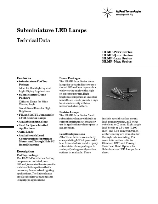
Dome PackagesThe HLMP-6xxx Series dome lamps for use as indicators use a tinted, diffused lens to provide a wide viewing angle with a high on-off contrast ratio. Highbrightness lamps use an untinted,nondiffused lens to provide a high luminous intensity within a narrow radiation pattern.Resistor LampsThe HLMP-6xxx Series 5 volt subminiature lamps with built in current limiting resistors are for use in applications where space is at a premium.Lead ConfigurationsAll of these devices are made by encapsulating LED chips on axial lead frames to form molded epoxy subminiature lamp packages. A variety of package configuration options is available. TheseFeatures• Subminiature Flat Top PackageIdeal for Backlighting and Light Piping Applications • Subminiature Dome PackageDiffused Dome for Wide Viewing AngleNondiffused Dome for High Brightness• TTL and LSTTL Compatible 5 Volt Resistor Lamps • Available in Six Colors • Ideal for Space Limited Applications • Axial Leads• Available with LeadConfigurations for Surface Mount and Through Hole PC Board MountingDescriptionFlat Top PackageThe HLMP-Pxxx Series flat top lamps use an untinted, non-diffused, truncated lens to provide a wide radiation pattern that is necessary for use in backlighting applications. The flat top lamps are also ideal for use as emitters in light pipe applications.Subminiature LED Lamps Technical DataHLMP-Pxxx Series HLMP-Qxxx Series HLMP-6xxx SeriesHLMP-70xx Seriesinclude special surface mount lead configurations, gull wing,yoke lead or Z-bend. Right angle lead bends at 2.54 mm (0.100inch) and 5.08mm (0.200 inch)center spacing are available for through hole mounting. For more information refer to Standard SMT and Through Hole Lead Bend Options for Subminiature LED Lamps data sheet.DH AS High High Device Standard AlGaAs EfficiencyPerf.Emerald Outline RedRed Red Orange Yellow Green Green Device Description [1]DrawingP105P205P405P305P505P605Untinted, Nondiffused,A Flat TopP102P202P402P302P502Untinted, Diffused,BFlat Top 6000/6001Q1016300Q40064006500Q600Tinted, Diffused Q105630564056505Untinted, Nondiffused,High Brightness Q150700070197040Tinted, Diffused, Low BCurrentQ155Nondiffused, Low Current660067006800Tinted, Diffused,Resistor, 5 V, 10 mA 662067206820Diffused, Resistor, 5 V,4 mADevice Selection GuidePart Number: HLMP-xxxxPackage D imensions(A) Flat Top Lamps2.21 1.96(0.087) (0.077)0.18 0.23(0.007) (0.009)2.08 (0.082) NOTES:1. ALL DIMENSIONS ARE IN MILLIMETRES (INCHES).2. PROTRUDING SUPPORT TAB IS CONNECTED TO CATHODE LEAD.* REFER TO FIGURE 1 FOR DESIGN CONCERNS.Package Dimensions (cont.)(B) Diffused and NondiffusedFigure 1. Proper Right Angle Mounting to a PC Board to Prevent Protruding Cathode Tab from Shorting to Anode Connection.NOTES:1. ALL DIMENSIONS ARE IN MILLIMETRES (INCHES).2. PROTRUDING SUPPORT TAB IS CONNECTED TO CATHODE LEAD.0.76 0.89(0.030) (0.035)R.0.79 (0.031) 0.53 (0.021)2.08 2.34(0.082) (0.092)2.21 1.96(0.087) (0.077)* REFER TO FIGURE 1 FOR DESIGN CONCERNS.NO. ANODE DOWN.YES. CATHODE DOWN.DH AS High High Standard AlGaAs Eff.Perf.EmeraldParameterRedRed Red Orange Yellow Green Green Units DC Forward Current [1]50303030203030m A Peak Forward Current [2]10003009090609090m A DC Forward Voltage 6666V (Resistor Lamps Only)Reverse Voltage (I R = 100 µA)5555555V Transient Forward Current [3]2000500500500500500500m A(10 µs Pulse)Operating T emperature Range:-55 to -40 to -55 to +100-40 to -20 to Non-Resistor Lamps +100+100+100+100°CResistor Lamps-40 to +85-20 to +85Storage Temperature Range °CFor Thru Hole Devices260°C for 5 SecondsWave Soldering Temperature [1.6 mm (0.063 in.) from body]For Surface Mount Devices:Convective IR 235°C for 90 Seconds Vapor Phase215°C for 3 MinutesAbsolute Maximum Ratings at T A = 25°C-55 to +100Notes:1. See Figure 5 for current derating vs. ambient temperature. Derating is not applicable to resistor lamps.2. Refer to Figure 6 showing Max. Tolerable Peak Current vs. Pulse Duration to establish pulsed operating conditions.3. The transient peak current is the maximum non-recurring peak current the device can withstand without failure. Do not operate these lamps at this high current.Electrical/Optical Characteristics, TA= 25°CStandard R edDeviceHLMP- Parameter Symbol Min.Typ.Max.Units Test Conditions6000Luminous Intensity[1]Iv 0.5 1.2mcd IF= 10 mA6001 1.3 3.2Forward Voltage VF 1.4 1.6 2.0V IF= 10 mAAll Reverse Breakdown VR 5.012.0V IR= 100 µAVoltageP005Included Angle Between125Half Intensity Points[2]2θ1/2Deg.All90OthersPeak WavelengthλPEAK655nmDominant Wavelength[3]λd640nmSpectral Line Half Width∆λ1/224nmAll Speed of Responseτs15nsCapacitance C100pF VF= 0; f = 1 MHzThermal Resistance RθJ-PIN 170°C/W Junction-to-CathodeLeadLuminous Efficacy[4]ηv65lm/WDeviceHLMP- Parameter Symbol Min.Typ.Max.Units Test Conditions P102 4.020.0P1058.630.0Q10122.045.0Q105Luminous Intensity Iv40200mcdQ150 1.0 1.8Q155 2.0 4.0Q101 1.8 2.2IF = 20 mAP205/P505Forward Voltage VF 1.8 2.2VQ101/Q105Q150/Q155 1.6 1.8IF= 1 mAAll Reverse Breakdown VR 5.015.0V IR= 100 µAVoltageP105125Q101/Q150Included Angle Between2θ1/290Deg.Half Intensity Points[2]Q105/Q15528Peak WavelengthλPEAK645nm Measured at PeakDominant Wavelength[3]λd637nmSpectral Line Half Width∆λ1/220nmAll Speed of Responseτs 30ns Exponential TimeConstant; e-t/τCapacitance C30pF VF= 0; f = 1 MHzThermal Resistance RθJ-PIN 170°C/W Junction-toCathode LeadLuminous Efficacy[4]ηv 80lm/WDH AS AlGaAs RedI F = 1 mAIF= 20 mAsDeviceHLMP-Parameter Symbol Min.Typ.Max.Units Test Conditions P202 1.0 5.0P205 1.08.06300 1.010.0IF= 10 mA 630510.040.07000Luminous Intensity[1]Iv 0.4 1.0mcd IF= 2 mA6600 1.3 5.0VF= 5.0 Volts 66200.8 2.06653 to 1.0 3.0IF = 10 mA6658All Forward Voltage VF 1.5 1.8 3.0V IF= 10 mA(Nonresistor Lamps)66009.613.0I F mA VF= 5.0 V6620 3.5 5.0All Reverse Breakdown VR 5.030.0V IR= 100 µAVoltageP2051256305Included Angle Between2θ1/228Deg.Half Intensity Points[2]All90DiffusedPeak WavelengthλPEAK635nm Measured at PeakDominant Wavelength[3]λd626nmSpectral Line Half Width∆λ1/240nmAll Speed of Responseτs90nsCapacitance C11pF VF= 0; f = 1 MHzThermal Resistance RθJ-PIN 170°C/W Junction-to-CathodeLeadLuminous Efficacy[4]ηv 145lm/WHigh Efficiency RedForward Current(Resistor Lamps)DeviceHLMP-Parameter Symbol Min.Typ.Max.Units Test Conditions P402 1.0 4.0P405Luminous Intensity Iv 1.06mcd IF= 10 mAQ400 1.08Forward Voltage VF 1.5 1.9 3.0V IF= 10 mAAll Reverse Breakdown VR 5.030.0V IR= 100 µAVoltageP405Included Angle Between125Half Intensity Points[2]2θ1/2Deg.Q40090Peak WavelengthλPEAK600nmDominant Wavelength[3]λd602nm Measured at PeakSpectral Line Half Width∆λ1/240nmAll Speed of Responseτs260nsCapacitance C4pF VF= 0; f = 1 MHzThermal Resistance RθJ-PIN 170°C/W Junction-to-CathodeLeadLuminous Efficacy[4]ηv 380lm/WOrangeYellowDeviceHLMP-Parameter Symbol Min.Typ.Max.Units Test Conditions P302 1.0 3.0P305 1.0 4.0IF = 10 mA6400 1.09.06405Luminous Intensity[1]Iv3.620mcd70190.40.6IF= 2 mA6700 1.4 5.0VF= 5.0 Volts 67200.9 2.06753 to 1.0 3.0IF = 10 mA6758All Forward Voltage VF 2.0 2.4V IF= 10 mA(Nonresistor Lamps)67009.613.0Forward Current IF m A VF= 5.0 V6720(Resistor Lamps) 3.5 5.0All Reverse Breakdown VR 5.050.0VVoltageP3051256405Included Angle Between2θ1/228Deg.Half Intensity Points[2]All90DiffusedPeak WavelengthλPEAK583nm Measured at PeakDominant Wavelength[3]λd585nmSpectral Line Half Width∆λ1/236nmAll Speed of Responseτs90nsCapacitance C15pF VF= 0; f = 1 MHzThermal Resistance RθJ-PIN 170°C/W Junction-to-CathodeLeadLuminous Efficacy[4]ηv500lm/WHigh Performance GreenDeviceHLMP-Parameter Symbol Min.Typ.Max.Units Test Conditions P502 1.0 3.0P505 1.6 6.36500 1.07.0IF= 10 mA 650510.040.07040Luminous Intensity[1]Iv 0.40.6mcd IF= 2 mA6800 1.6 5.0VF= 5.0 Volts 68200.8 2.06853 to 1.0 3.0IF = 10 mA6858All Forward Voltage VF 2.1 2.7V IF= 10 mA(Nonresistor Lamps)68009.613.0Forward Current IF m A VF= 5.0 V6820(Resistor Lamps) 3.5 5.0All Reverse Breakdown VR 5.050.0V IR= 100 µAVoltageP5051256505Included Angle Between2θ1/228Deg.Half Intensity Points[2]All90DiffusedPeak WavelengthλPEAK565nmDominant Wavelength[3]λd569nmSpectral Line Half Width∆λ1/228nmAll Speed of Responseτs500nsCapacitance C18pF VF= 0; f = 1 MHzThermal Resistance RθJ-PIN 170°C/W Junction-to-CathodeLeadLuminous Efficacy[4]ηv595lm/WNotes:1. The luminous intensity for arrays is tested to assure a2.1 to 1.0 matching between elements. The average luminous intensity for anarray determines its light output category bin. Arrays are binned for luminous intensity to allow I v matching between arrays.2. θ1/2 is the off-axis angle where the luminous intensity is half the on-axis value.3. Dominant wavelength, λd, is derived from the CIE Chromaticity Diagram and represents the single wavelength that defines the color ofthe device.4. Radiant intensity, Ie , in watts/steradian, may be calculated from the equation Ie=Iv/ηv, where Ivis the luminous intensity incandelas and ηvis the luminous efficacy in lumens/watt.DeviceHLMP-Parameter Symbol Min.Typ.Max.Units Test ConditionsP605Luminous Intensity Iv 1.0 1.5mcd IF= 10 mAQ600 1.0 1.5Forward Voltage VF 2.2 3.0V IF= 10 mAReverse Breakdown VR 5.0V IR= 100 µAVoltageP605Included Angle Between125Half Intensity Points[2]2θ1/2Deg.Q60090Peak WavelengthλPEAK558nmDominant Wavelength[3]λd560nm Measured at PeakSpectral Line Half Width∆λ1/224nmP605/Q600Speed of Responseτs3100nsCapacitance C35pF VF= 0; f = 1 MHzThermal Resistance RθJ-PIN 170°C/W Junction-to-CathodeLeadLuminous Efficacy[4]ηv 656lm/WEmerald Green[1]Note:1. Please refer to Application Note 1061 for information comparing standard green and emerald green light ouptut degradation.Standard Red, DH As AlGaAs Red Standard Red and DH ASAlGaAs RedHigh Efficiency Red, Orange,Yellow, and High Performance GreenHER, Orange, Yellow, and High Performance Green,and Emerald GreenLow CurrentFigure 1. Relative Intensity vs. Wavelength.Figure 2. Forward Current vs. Forward Voltage. (Non-Resistor Lamp)Figure 3. Relative Luminous Intensity vs. Forward Current. (Non-Resistor Lamp)Figure 4. Relative Efficiency (Luminous Intensity per Unit Current) vs. Peak Current (Non-Resistor Lamps).Figure 5. Maximum Forward dc Current vs. Ambient Temperature. Derating Based on T J MAX = 110°C (Non-Resistor Lamps).Figure 6. Maximum Tolerable Peak Current vs. Pulse Duration. (I DC MAX as per MAX Ratings) (Non-Resistor Lamps).Standard RedDH As AlGaAs RedStandard Red HER, Orange, Yellow, and HighPerformance GreenDH As AlGaAs RedHER, Orange, Yellow, and High Performance Green,and Emerald GreenFigure 9. Relative Intensity vs. Angular Displacement.Figure 7. Resistor Lamp Forward Current vs. Forward Voltage.Figure 8. Resistor Lamp Luminous Intensity vs.Forward Voltage. Data subject to change.Copyright © 1999 Agilent Technologies Obsoletes 5968-2537E (2/96)5968-7825E (11/99)。
- 1、下载文档前请自行甄别文档内容的完整性,平台不提供额外的编辑、内容补充、找答案等附加服务。
- 2、"仅部分预览"的文档,不可在线预览部分如存在完整性等问题,可反馈申请退款(可完整预览的文档不适用该条件!)。
- 3、如文档侵犯您的权益,请联系客服反馈,我们会尽快为您处理(人工客服工作时间:9:00-18:30)。
DescriptionThese non-diffused lamps are designed to produce a bright light source and smooth radiationpattern. A slight tint is added to the lens for easy color identification.This lamp has been designed with aHLMP-C115, HLMP-C117, HLMP-C123, HLMP-C215, HLMP-C223,HLMP-C315, HLMP-C323, HLMP-C415, HLMP-C423, HLMP-C515,HLMP-C523, HLMP-C615, HLMP-C623Features•Very high intensity •Exceptional uniformity •Microtint lens for color identification•Consistent viewability All colors: AlGaAs RedHigh Efficiency Red Yellow Orange GreenEmerald Green •15° and 25° family•Tape and reel options available •Binned for color and intensity Applications•Ideal for backlighting front panels*•Used for lighting switches •Adapted for indoor and outdoor signsAgilentT-13/4 Super Ultra-Bright LED LampsData Sheet20mil lead frame, enhanced flange, and tight meniscus controls, making it compatible with radial lead automated insertion equipment.Selection GuidePart Number Luminous Intensity Iv (mcd) Color2θ1/2[1]Standoff Leads HLMP-Min.Max.DH AS AlGaAs15No C115290.0–C115-O00xx290.0–C115-OP0xx290.01000.0Yes C117-OP0xx290.01000.025No C12390.2–C123-L00xx90.2–Red15No C215138.0–C215-M00xx138.0–C215-MN0xx138.0400.025No C22390.2–C223-L00xx90.2–C223-MN0xx138.0400.0 Yellow15No C315147.0–C315-L00xx147.0–C315-LM0xx147.0424.025No C32396.2–C323-K00xx96.2–C323-KL0xx96.2294.0 Orange15No C415138.0–C415-M00xx138.0–C415-M0D0xx138.0–C415-MN0xx138.0400.025No C42390.2–C423-L00xx90.2–C423-LM0xx90.2276.0 Green15No C515170.0–C515-L00xx170.0C515-LM0xx170.0490.025No C52369.8–C523-J00xx69.8–C523-KL0xx111.7340.0 Emerald Green15No C61517.0–C615-G00xx17.0–25No C623 6.7–C623-E00xx 6.7–Part Numbering SystemHLMP - C x xx - x x x xxMechanical Options00: Bulk01: Tape & Reel, Crimped Leads02: Tape & Reel, Straight LeadsB2: Right Angle Housing, Even LeadsUQ: Ammo Pack, Horizontal LeadsColor Bin Options0: Full Color Bin DistributionD: Color Bins 4 & 5 onlyMaximum Iv Bin Options0: Open (No Maximum Limit)Others: Please refer to the Iv Bin TableMinimum Iv Bin OptionsPlease refer to the Iv Bin TableViewing Angle & Standoffs Options15: 15 Degree, without Standoffs17: 15 Degree, with Standoffs23: 25 Degree, without StandoffsColor Options1. AS AlGaAs Red2. High Efficiency Red3. Yellow4. Orange5. Green6. Emerald GreenPackage OptionsC: T-1 3/4 (5 mm)Absolute Maximum Ratings at T A = 25°CHighHighDH AS Efficiency Performance AlGaAs Red and Green and ParameterRed Orange Yellow Emerald Green Units DC Forward Current [1]30302030mA Transient Forward Current [2]500500500500mA (10 µsec Pulse)Reverse Voltage (Ir = 100 µA)5555V LED Junction Temperature 110110110110°C Operating Temperature Range –20 to +100–55 to +100–20 to +100°C Storage Temperature Range –55 to +100°CWave Soldering Temperature 250°C for 3 seconds [1.59 mm (0.063 in.) from body]Lead Solder Dipping Temperature 260°C for 5 seconds[1.59 mm (0.063 in.) from body]Notes:1. See Figure 5 for maximum current derating vs. ambient temperature.2. The transient current is the maximum nonrecurring peak current the device can withstand without damaging the LED die and wire bond.Package DimensionsHLMP-Cx15 and HLMP-Cx23HLMP-Cx17(0.039)NOTES:1. ALL DIMENSIONS ARE IN MILLIMETERS (INCHES).2. LEADS ARE MILD STEEL, SOLDER DIPPED.3. AN EPOXY MENISCUS MAY EXTEND ABOUT 0.5 mm (0.020 in.) DOWN THE LEADS.± 0.20± 0.008)Electrical Characteristics at T A = 25°CForward Reverse Capacitance Speed of ResponseVoltage Breakdown C (pF)Thermalτs (ns)Vf (Volts)Vr (Volts)Vf = 0Resistance Time Constant@ If = 20 mA@ Ir = 100 µA f = 1 MHz RθJ-PIN e-t/τsPart Number Typ.Max.Min.Typ.(°C/W)Typ.HLMP-C115 1.8 2.253021030HLMP-C117HLMP-C123HLMP-C215 1.9 2.651121090HLMP-C223HLMP-C315 2.1 2.651521090HLMP-C323HLMP-C415 1.9 2.654210280HLMP-C423HLMP-C515 2.2 3.0518210260HLMP-C523HLMP-C615 2.2 3.0518210260HLMP-C623Optical Characteristics at T A = 25°CLuminous Color,ViewingIntensity Peak Dominant Angle LuminousIv (mcd)Wavelength Wavelength2θ1/2Efficacy@ 20 mA[1]λpeak (nm)λd[2] (nm)(Degrees)[3]ηvPart Number Min.Typ.Typ.Typ.Typ.(lm/w) HLMP-C1152906006456371180HLMP-C117HLMP-C1239020026HLMP-C215138300635626171459017023HLMP-C315146300583585175009617025HLMP-C415138300600602173809017023HLMP-C515170300568570205956917028HLMP-C61517455585602065662728Notes:1. The luminous intensity, Iv, is measured at the mechanical axis of the lamp package. The actual peak of the spatial radiation pattern may not bealigned with this axis.2. The dominant wavelength, λd, is derived from the CIE Chromaticity Diagram and represents the color of the device.3. 2θ1/2 is the off-axis angle where the luminous intensity is 1/2 the on-axis intensity.Figure 1. Relative intensity vs. wavelength.Figure 2. Forward current vs. forward voltage (non-resistor lamp).Figure 3. Relative luminous intensity vs. forward current.WAVELENGTH – nmR E L A T I V E I N T E N S I T Y1.00.50I F – F O R W A R DC U R R E N T – m AV F – FORWARD VOLTAGE – VI F – F O R W A R D C U R R E N T – m AV F – FORWARD VOLTAGE – VHIGH EFFICIENCY RED, ORANGE,YELLOW, AND HIGH PERFORMANCEGREEN, EMERALD GREENR E L A T I V E L U M I N O U S I N TE N S I T Y (N O R M A L I Z E D A T 20 m A )I F – DC FORWARD CURRENT – mA R E L A T I V E L U M I N O U S I N T E N S I T Y (N O R M A L I Z E D A T 20 m A )0I DC – DC CURRENT PER LED – mA10201.60.80.4515301.2250.20.61.01.4HER, ORANGE, YELLOW, AND HIGH PERFORMANCE GREEN, EMERALD GREENFigure 5. Maximum forward dc current vs. ambient temperature. Derating based on T j MAX = 110°C.Figure 4. Relative efficiency (luminous intensity per unit current) vs. peak current.Figure 6. Relative luminous intensity vs. angular displacement. 15 degree family.R E L A T I V E E F F I C I E N C Y (N O R M A L I Z E D A T 20 m A )0I PEAK – PEAK FORWARD CURRENT – mA0.60.8300201001.21.00.20.45020010DH As AlGaAs REDηP E A K – R E L A T I V E E F F I C I E N C Y (N O R M A L I Z E D A T 20 m A )I PEAK – PEAK FORWARD CURRENT – mAHER, ORANGE, YELLOW, HIGHPERFORMANCE GREEN, EMERALD GREENI F – F O R W A R D C U R R E NT – m AT A – AMBIENT TEMPERATURE – °C DH As AlGaAs REDI F – F O R W A R D C U R R E N T – m AT A – AMBIENT TEMPERATURE – °CHER, ORANGE, YELLOW, AND HIGH PERFORMANCE GREEN, EMERALD GREEN N O R M A L I Z E D L U M I N O U S I N T E N S I T Y10ANGULAR DISPLACEMENT – DEGREES0.80.60.50.70.2450.10.30.4403530252010515-5-10-15-20-25-30-35-40-450.9Figure 7. Relative luminous intensity vs. angular displacement. 25 degree family.Intensity Bin Limits Intensity Range (mcd)ColorBin Min.Max.L 101.5162.4M 162.4234.6N 234.6340.0O 340.0540.0P 540.0850.0Q 850.01200.0R 1200.01700.0Red/OrangeS 1700.02400.0T 2400.03400.0U 3400.04900.0V 4900.07100.0W 7100.010200.0X 10200.014800.0Y 14800.021400.0Z 21400.030900.0L 173.2250.0M 250.0360.0N 360.0510.0O 510.0800.0P 800.01250.0YellowQ 1250.01800.0R 1800.02900.0S 2900.04700.0T 4700.07200.0U 7200.011700.0V 11700.018000.0W18000.027000.0N O R M A L I Z E D L U M I N O U S I N T E N S I T Y10ANGULAR DISPLACEMENT – DEGREES0.80.60.50.70.2450.10.30.4403530252010515-5-10-15-20-25-30-35-40-450.9Intensity Bin Limits, continuedIntensity Range (mcd) Color Bin Min.Max.E7.612.0F12.019.1G19.130.7H30.749.1I49.178.5J78.5125.7K125.7201.1L201.1289.0 Green/M289.0417.0 Emerald Green N417.0680.0O680.01100.0P1100.01800.0Q1800.02700.0R2700.04300.0S4300.06800.0T6800.010800.0U10800.016000.0V16000.025000.0W25000.040000.0 Maximum tolerance for each bin limit is ± 18%.Color CategoriesLambda (nm)Color Category #Min.Max.6561.5564.55564.5567.5 Green4567.5570.53570.5573.52573.5576.51582.0584.53584.5587.0 Yellow2587.0589.54589.5592.05592.0593.01597.0599.52599.5602.03602.0604.5 Orange4604.5607.55607.5610.56610.5613.57613.5616.58616.5619.5 Tolerance for each bin limit is ± 0.5 nm.Mechanical Option MatrixMechanical Option Code Definition00Bulk Packaging, minimum increment 500 pcs/bag01Tape & Reel, crimped leads, minimum increment 1300 pcs/bag02Tape & Reel, straight leads, minimum increment 1300 pcs/bagB2Right Angle Housing, even leads, minimum increment 500 pcs/bagUQ Ammo Pack, horizontal leads, in 1K minimum incrementNote:All categories are established for classification of products. Products may not be available in all categories. Please contact your local Agilent representative for further clarification/information./semiconductorsFor product information and a complete list ofdistributors, please go to our web site.For technical assistance call:Americas/Canada: +1 (800) 235-0312 or(916) 788-6763Europe: +49 (0) 6441 92460China: 10800 650 0017Hong Kong: (+65) 6756 2394India, Australia, New Zealand: (+65) 6755 1939Japan: (+81 3) 3335-8152 (Domestic/Interna-tional), or 0120-61-1280 (Domestic Only)Korea: (+65) 6755 1989Singapore, Malaysia, Vietnam, Thailand,Philippines, Indonesia: (+65) 6755 2044Taiwan: (+65) 6755 1843Data subject to change.Copyright © 2004 Agilent Technologies, Inc.Obsoletes 5965-6165ENovember 11, 20045988-2149EN。