GS-M500BT 二维影像式规格书
M5000直读光谱仪用户手册

供货和运输
具体装运要求依照订购合同上相应条款。 开箱时请认真阅读包装材料上的相应信息,确保开箱货物的完整与无损。请尽量保留产品外包装,以 便在需要返修产品时使用。
质保和维修
具体的质保和维修的要求依照订购合同上相应条款。
II
阅读说明
保修期内且符合保修范围,将提供免费维修服务,主要包含保修内产品维修、备件维修更换、技术支 持及常规现场服务等。 超过保修期或者在保修期内发生如下故障,均属于保外维修,不提供免费保修服务,故障包括但不限 于: 1)由于使用不当(进水、腐蚀、失火、强电串入等) 。 2)因用户擅自搬运仪器造成仪器不能正常使用。 3)因用户擅自打开或拆卸后造成器件的损坏。 4)不可抗力(地震、雷击、洪水等)造成的损坏。 5)未经允许,产品内部擅自改动。 6)未按用户手册及培训规定使用,引起产品损坏的。 关于本公司所研发制造的产品,在处理废旧产品方面本公司严格遵守相关国家规定。
技术支持
请联系本公司的客户服务部: 全国免费客服热线:400 7007 555 传真:0571-85012001 E-MAIL:tech_support@ 网址:
声明
本手册对用户不承担法律责任,所有的法律条款请见相应的合同。 聚光科技版权所有,如有改动,恕不另行通知;未经允许,不得翻印。
许可标识
本分析仪已获得国家计量器具型式批准证书和制造计量器具许可证:
批注 [y1]: 有参考标准吗?
I
阅读说明
注意和警示信息
本手册介绍了 M5000 直读光谱仪的具体应用,以及如何启动、操作和维护该光谱仪。需特别指出的 是,本手册中的注意和警示信息至关重要(在手册中强调显示,并加有适当的图标) ,能有效地避免不恰 当的操作。 本手册所述产品的开发、制造、测试都把适当的安全标准放在首位。因此,如果用户按照本手册指导 进行装配、核准使用和维护,可避免因操作不当而造成的常规使用中的财产损失和人身危害。 本手册中有相关注意和警示信息。此类信息以特定图标显示,并附有相应的解释文字。本手册所使用 注意及警告信息释意如下: 图标 说明 提示标记和信息——表示在产品使用过程中提醒用户的一般信息,或本手册 中需一般关注的部分。 注意标记和信息——表示在产品使用过程中需注意的重要信息,或本手册中 需特别关注的部分。 警告标记和信息——表示在产品使用中,若没有遵守适当的安全措施,将会 造成本仪器无法正确测量,特别严重的情况可能会造成重大人身伤亡或财产 损坏事故。
泰特电子M5000-00-102ii产品说明书

Tait Orca 5000 Handportable RadiosService ManualIssue 03September 2001IPN: M5000-00-102PrefaceEnquiries and CommentsIf you have any enquiries regarding this manual, or any comments, suggestions and notifications of errors, please contact Customer Support, Tait Electronics Ltd, Christchurch, New Zealand. Refer to / for more information.DisclaimerThere are no warranties extended or granted by this manual. Tait Electronics Ltd accepts no responsibility for damage arising from use of the information contained in the manual or of the equipment and software it describes. It is the responsibility of the user to ensure that use of such information, equipment and software complies with the laws, rules and regulations of the applica-ble jurisdictions.Updating Equipment And ManualsIn the interests of improving performance, reliability or servicing, Tait Electronics Ltd reserve the right to update their equipment and/or manuals without prior notice.CopyrightAll information contained in this manual is the property of Tait Electronics Ltd. All rights are reserved. This manual may not, in whole or in part, be copied, photocopied, reproduced, translat-ed, stored, or reduced to any electronic medium or machine-readable form, without prior written permission from Tait Electronics Limited. All trade names referenced are the service mark, trade-mark or registered trademark of the respective manufacturers.Publication HistoryIssue Publication Date Product Code Description01May 2001M5000-00-100First revision.02June 2001M5000-00-101New revision and cover.03September 2001M5000-00-102New revision (Section E).Contacting Tait Electronics LtdTo contact your nearest Tait Electronics regional office, refer to the Tait Website:/ii Preface09/01 IPN: M5000-00-10209/01 IPN: M5000-00-102iiiContentsPart A: IntroductionServicing Tait Orca 5000 handportables Servicing Tait Orca 5000 handportables .........................................................................................................................................................................................................................................................A-3A-3WWW technical support .....................................................................................................................A-3What does this manual contain? ..........................................................................................................A-3What is included in the calibration service kit? ....................................................................................A-3Programming kit ..................................................................................................................................A-4Conventions .........................................................................................................................................A-4The Tait Orca 5000 series of handportables The Tait Orca 5000 series of handportables ..........................................................................................................................................................................................................................................A-5A-5The Tait Product Code Scheme ............................................................................................................A-5Operating instructions .........................................................................................................................A-6Accessories ...........................................................................................................................................A-6Important information ......................................................................................................................................................................................................................A-10A-10Basic servicing precautions ................................................................................................................A-10Programming .....................................................................................................................................A-10Calibrating .........................................................................................................................................A-11Test facilities ......................................................................................................................................A-11Basic maintenance .............................................................................................................................A-11Part B: Radio specifications and circuit descriptionsRadio specifications Radio specifications ....................................................................................................................................................................................................................................B-3General specifications........................................................................................................................... B-3Receiver performance........................................................................................................................... B-3Transmitter performance..................................................................................................................... B-4Tait Orca 5000 66-88MHz. Conventional and Trunked Radio Specifications...................................... B-5Tait Orca 5000 136-174MHz. Conventional and Trunked Radio Specifications.................................. B-6Tait Orca 5000 174-225MHz. Conventional and Trunked Radio Specifications.................................. B-7Tait Orca 5000 336-400MHz. Conventional and Trunked Radio Specifications.................................. B-8Tait Orca 5000 400-470MHz. Conventional and Trunked Radio Specifications.................................. B-9Tait Orca 5000 450-530MHz. Conventional and Trunked Radio Specifications................................ B-10Tait Orca 5000 806-870MHz. Conventional and Trunked Radio Specifications................................ B-11Tait Orca 5000 896-941MHz. Conventional and Trunked Radio Specifications................................ B-12iv 09/01 IPN: M5000-00-102Circuit descriptions Circuit descriptions ...................................................................................................................................................................................................................................................................................................................................................B-13B-13Transmitter ........................................................................................................................................B-13Transmit (Tx) audio ...........................................................................................................................B-13Receiver ..............................................................................................................................................B-13Receive (Rx) audio ..............................................................................................................................B-13Synthesiser and VCO ..........................................................................................................................B-14Power supplies ...................................................................................................................................B-14Accessory connector interface ............................................................................................................B-15Universal band versus wideband IF filtering ......................................................................................B-15Part C: Diagnostics and fault findingTest facilities Test facilities ..........................................................................................................................................................................................................................................................................................................................................................................................C-3C-3Error codes ...........................................................................................................................................C-3Test commands..................................................................................................................................... C-5Calculating the parameters required for test command 101................................................................. C-7Fault finding charts Fault finding charts ............................................................................................................................................................................................................................................................................................................................................................C-8C-8Fault finding – Radio cannot be switched on .......................................................................................C-9Fault finding – Cannot change channel ..............................................................................................C-10Fault finding – No serial communication ...........................................................................................C-11Fault finding – Receive faults ..............................................................................................................C-12Fault finding – Cannot transmit .........................................................................................................C-13Fault finding – No transmit audio ......................................................................................................C-14Part D: Servicing the radioServicing the radio Servicing the radio ........................................................................................................................................................................................................................................D-3Screw head types ..................................................................................................................................D-3Disassembling the radio Disassembling the radio ......................................................................................................................................................................................................................D-4Removing the front panel from the chassis ..........................................................................................D-4Removing the shield sub-assembly from the chassis ............................................................................D-5Removing the PCB from the chassis .....................................................................................................D-6Removing the rear panel ......................................................................................................................D-7Replacing key mechanicaland ancillary devices and ancillary devices ..................................................................................................................................................................................................................................D-8Replacing the lens (Orca 5020, Orca 5035 and Orca 5040) ..................................................................D-8Replacing the PTT keypad ....................................................................................................................D-8Replacing the speaker ...........................................................................................................................D-9Replacing the LCD display (Orca 5020, Orca 5035 and Orca 5040) .....................................................D-909/01 IPN: M5000-00-102vReplacing the shield, user interface PCB assembly and polyester dome(Orca 5020, Orca 5035 and Orca 5040) ..............................................................................................D-12Replacing the antenna connector, channel selector switch and volume control switch .....................D-12Replacing the microphone .................................................................................................................D-12Replacing the battery and speaker contacts .......................................................................................D-12Replacing the tact switch ....................................................................................................................D-12Reassembling the radio Reassembling the radio .................................................................................................................................................................................................................................................................................................................................D-13D-13Rear panel reassembly and replacing the auxiliary flexible PCB ........................................................D-13Fitting the PCB to the chassis and replacing the RF out assembly ......................................................D-14Fitting the shield to the chassis ..........................................................................................................D-14Fitting the front panel to the chassis ..................................................................................................D-15Spares kits Spares kits .............................................................................................................................................................................................................................................................................................................................................................................................D-16D-16Orca 5010/5030 spares kit (TOPA-SP-401)....................................................................................... D-17Orca 5035 spares kit (TOPA-SP-402)................................................................................................. D-18Orca 5020/5040 spares kit (TOPA-SP-403)....................................................................................... D-19Orca 5010/5030 Re-skinning kit (TOPA-SP-404).............................................................................. D-20Orca 5035 Re-skinning kit (TOPA-SP-405)........................................................................................ D-20Orca 5020/5040 Re-skinning kit (TOPA-SP-406).............................................................................. D-20Orca 5020/5035/5040 User Interface PCB and Shield (TOPA-SP-407)............................................. D-20Part E: Battery packs and chargersBattery packs Battery packs ..........................................................................................................................................................................................................................................................E-3Battery shift life .....................................................................................................................................E-3Disposing of used nickel-cadmium batteries .........................................................................................E-4Battery chargers Battery chargers ................................................................................................................................................................................................................................................E-5Desktop fast charger Desktop fast charger ..................................................................................................................................................................................................................................E-6Fast charger operation ..........................................................................................................................E-6Using the fast charger ............................................................................................................................E-9Repairing the fast charger ...................................................................................................................E-10Desktop trickle charger Desktop trickle charger ......................................................................................................................................................................................................................E-12Trickle charger operation ....................................................................................................................E-12Using the trickle charger .....................................................................................................................E-13Repairing the trickle charger ...............................................................................................................E-13Troubleshooting .................................................................................................................................E-14vi 09/01 IPN: M5000-00-102Multi-charger Multi-charger .................................................................................................................................................................................................................................................................................................................................................................................E-15E-15Multi-charger operation ......................................................................................................................E-15Repairing the multi-charger ................................................................................................................E-15Fuse replacement ................................................................................................................................E-16Part F: AccessoriesTait Orca 5000 Accessory Connector Tait Orca 5000 Accessory Connector ..................................................................................................................................................................................F-3Connecting an Accessory ......................................................................................................................F-3Connecting a Headset ............................................................................................................................F-6Accessory Connector Signal Descriptions .............................................................................................F-77.5 mm Accessory Adaptor 7.5 mm Accessory Adaptor ................................................................................................................................................................................................................F-9Tait Orca Vehicle Kit ...............................................................................................................F-11Product Codes .....................................................................................................................................F-11Installing a Vehicle Kit ........................................................................................................................F-11Vehicle Kit Operation ..........................................................................................................................F-11Vehicle Kit Specifications ....................................................................................................................F-13Servicing the Vehicle Kit .....................................................................................................................F-14Spares Kits ...........................................................................................................................................F-15Vehicle kit spares kit (TOPA-SP-301).................................................................................................. F-16Vehicle kit reskinning kit (TOPA-SP-302)........................................................................................... F-17Custom Modifications .........................................................................................................................F-18Vehicle Kit Circuit Descriptions ..........................................................................................................F-20Part G: Additional informationGlossary Glossary ........................................................................................................................................................................................................................................................................................................................................................................................................G-3Tait Electronics Limited Software Licence Agreement Tait Electronics Limited Software Licence Agreement ..........................................................................................................................G-7A P A R T IntroductionThis part provides an introduction to servicing Tait Orca 5000 handportables. It includes an outline of the Tait Orca 5000 handportable range of products and precautions that should be taken before servicing Tait Orca 5000 handportables.Detailed servicing instructions and information about spare parts are found in Part D: Servicing the radio .ContentsServicing Tait Orca 5000 handportables Servicing Tait Orca 5000 handportables .....................................................................................................................................................................A-3A-3WWW technical support ......................................................................................A-3What does this manual contain? ...........................................................................A-3What is included in the calibration service kit? .....................................................A-3Programming kit ...................................................................................................A-4Conventions ..........................................................................................................A-4The Tait Orca 5000 series of handportables The Tait Orca 5000 series of handportables ......................................................................................................................................................A-5A-5Product codes ........................................................................................................A-5The Tait Orca Product Naming Convention .........................................................A-5Operating Instructions ..........................................................................................A-6Accessories ............................................................................................................A-6Important information Important information ................................................................................................................................................................................................................................................A-11A-11Basic servicing precautions .................................................................................A-11Programming ......................................................................................................A-11Calibrating ..........................................................................................................A-11Test facilities .......................................................................................................A-11Basic maintenance ...............................................................................................A-12。
科学公司的双目微观镜说明书

3B SCIENTIFIC ®PHYSICS1Binokulares Mikroskop, Modell 500 LED mit Polarisations-einrichtung 1013146Bedienungsanleitung07/13 ALF1 Okular2 Tubus3 Schlitz zur Aufnahme desAnalysators4 Revolver mit Objektiven5 Objektführer6 Objekttisch7 Kondensor mit Irisblendeund Filterhalter 8 Beleuchtung9 Beleuchtungsregler 10 Netzschalter11 Koaxialtrieb des Objektti-sches12 Grob- und Feintrieb mitFeststellbremse13 Feststellschraube für Ob-jekttisch 14 Stativ15 Feststellschraube für Mikro-skopkopf1. Sicherheitshinweise•Elektrischer Anschluss des Mikroskops darf nur an geerdeten Steckdosen erfolgen.2. Beschreibung, technische Daten Das binokulare Mikroskop ermöglicht die zwei-dimensionale Betrachtung von Objekten (dünne Schnitte von Pflanzen- oder Tieren) in 40- bis 1500-facher Vergrößerung. Es ist mit einer Pola-risationseinrichtung bestückt.Stativ: Robustes Ganzmetallstativ, Stativarm fest mit Fuß verbunden; Fokussierung über beidseitig am Stativ angebrachte koaxiale Stell-knöpfe für Fein- und Grobtrieb mit Kugellager und Feststellbremse; einstellbarer Anschlag zum Schutz der Objektträger und Objektive. Fokussierbereich: 15 mm; Einteilung der Feinfo-kussierung: 0,002 mmTubus: Binokularer Siedentopf-Kopf, Schräg-einblick 30°, Kopf um 360° drehbar, Augenab-stand zwischen 54 mm und 75 mm einstellbar, Dioptrienausgleich ±5 für beide OkularePolarisationseinrichtung: Polarisator und Ana-lysatorOkular: Weitfeld-Okularpaare WF 10x 18 mm und WF 15x 13 mmObjektive: Invers geneigter Objektivrevolver mit 4 DIN plan achromatischen Objektiven 4x / 0,10, 10x / 0,25, 40x / 0,65, 100x / 1,25 (Ölimmersion) Vergrößerung: 40x – 1500xObjekttisch: x-y-Kreuztisch, 155 x 145 mm 2, mit Objektführer und koaxialen Stellknöpfen senk-recht zum Objekttisch, Stellbereich 50 x 76 mm 2Beleuchtung: Im Fuß integrierte, regelbare LED-Beleuchtung; universale Spannungsver-sorgung 85 V bis 265 V, 50/60 HzKondensor: Abbe Kondensor N.A.1,25 mit Iris-blende, Filterhalter und Blaufilter, fokussierbar über ein ZahnstangengetriebeAbmessungen: ca. 306 x 190 x 407 mm³ Masse: ca. 6,6 kg3. Auspacken und ZusammenbauDas Mikroskop wird in einem Karton aus Styro-por geliefert.•Nach Entfernen des Klebebands den Behäl-ter vorsichtig öffnen. Dabei darauf achten, dass keine der optischen Teile (Objektive und Okulare) herausfallen.•Um Kondensation auf den optischen Be-standteilen zu vermeiden, das Mikroskop solange in der Verpackung belassen, bis es die Raumtemperatur angenommen hat. •Das Mikroskop mit beiden Händen (eine Hand am Stativarm und eine am Fuß) ent-nehmen und auf eine ebene Fläche stellen. •Die Objektive sind separat in Döschen ver-packt. Sie werden in der Reihenfolge vom Objektiv mit dem kleinsten bis zum Objektivmit dem größten Vergrößerungsfaktor im Uhrzeigersinn hinten beginnend in die Öff-nungen der Revolverplatte geschraubt. •Anschließend den Mikroskopkopf auf das Stativ setzen und mit der Feststellschraube fixieren. Okulare in den Tubus einsetzen.4. Bedienung4.1 Allgemeine Hinweise•Das Mikroskop auf einen ebenen Tisch stel-len.•Das zu betrachtende Objekt in die Mitte des Objekttisches platzieren und in der Objekt-führung festklemmen.•Netzkabel anschließen und Beleuchtung anschalten.•Objektträger so in den Strahlengang schie-ben, dass das Objekt vom Strahlengang deutlich durchstrahlt wird.•Augenabstand einstellen bis nur ein Licht-kreissichtbar ist.•Diopterstärke den Augen anpassen.•Zur Erreichung eines hohen Kontrasts Hin-tergrundbeleuchtung mittels der Irisblende und der regelbaren Beleuchtung einstellen. •Das Objektiv mit der kleinsten Vergrößerung in den Strahlengang drehen. Ein Klick-Ton zeigt die richtige Stellung an.Hinweis: Es ist am besten mit der kleinsten Vergrößerung zu beginnen, um zuerst größere Strukturdetails zu erkennen. Der Übergang zu einer stärkeren Vergrößerung zur Betrachtung feinerer Details erfolgt durch Drehen des Revol-vers bis zum gewünschten Objektiv. Bei Ver-wendung des Objektivs 100x muss Öl auf den Objektträger gegeben werden.Die Stärke der Vergrößerung ergibt sich aus dem Produkt des Vergrößerungsfaktors des Okulars und des Objektivs.•Mit der Feststellbremse geeignete Span-nung des Fokusiersystems einstellen.•Mit dem Triebknopf für Grobtrieb das un-scharf abgebildete Präparat scharf stellen, dabei darauf achten, dass das Objektiv den Objektträger nicht berührt. (Beschädigungs-gefahr)•Anschließend mittels Feintrieb die Bildschär-fe nachregeln.•Zur Benutzung von Farbfiltern Filterhalter ausschwenken und Farbfilter einlegen. •Mittels des Koaxialtriebs des Kreuztisches lässt sich das zu betrachtende Objekt auf die gewünschte Stelle schieben.•Nach Gebrauch sofort die Beleuchtung aus-schalten.•Das Mikroskop mit keinen Flüssigkeiten in Kontakt kommen lassen.•Das Mikroskop keinen mechanischen Belas-tungen aussetzen.•Optische Teile des Mikroskops nicht mit den Fingern berühren.•Bei Beschädigungen oder Fehlern das Mik-roskop nicht selbst reparieren.4.2 Verwendung der Polarisationseinrich-tung•Analysator in den Schlitz am Objektivrevol-ver einsetzen.•Polarisator auf die Lichtaustrittsöffnung der Beleuchtungseinrichtung auflegen.•Durch Drehen des Polarisators Polarisator und Analysator in gekreuzte Stellung brin-gen, so dass man einen schwarzen Hinter-grund erhält.Doppelbrechende Strukturen sollten auf dem dunklen Hintergrund nun hell aufleuchten. Ist dies nicht der Fall so könnte die Möglichkeit bestehen, dass die Schwingungsrichtung des Objektes identisch mit der Polarisationsrichung ist. Durch Drehen der Filter oder des Präparates selbst kann getestet werden, ob dies der Fall ist.23B Scientific GmbH • Rudorffweg 8 • 21031 Hamburg • Deutschland • Technische Änderungen vorbehalten © Copyright 2013 3B Scientific GmbHDoppelbrechende Strukturen leuchten nach jeder 90° Drehung hell auf und erscheinen da-zwischen dunkel. Isotrope, nicht doppelbre-chende Strukturen hingegen bleiben in jeder Position dunkel.4.3 Sicherungswechsel• Stromversorgung ausschalten und unbe-dingt Netzstecker ziehen.• Sicherungshalter an der Rückseite des Mik-roskops mit einem flachen Gegenstand (z.B. Schraubenzieher) herausschrauben.• Sicherung ersetzen und Halter wieder ein-schrauben.5. Aufbewahrung, Reinigung, Entsorgung• Das Mikroskop an einem sauberen, trocke-nen und staubfreien Platz aufbewahren.• Bei Nicht-Benutzung das Mikroskop immer mit der Staubschutzhülle abdecken.•Das Mikroskop keinen Temperaturen unter 0°C und über 40°C sowie keiner relativen Luftfeuchtigkeit über 85% aussetzen.• Vor Pflege- und Wartungsarbeiten ist immer der Netzstecker zu ziehen.•Zur Reinigung des Mikroskops keine ag-gressiven Reiniger oder Lösungsmittel ver-wenden.• Objektive und Okulare zum Reinigen nicht auseinander nehmen.•Bei starker Verschmutzung das Mikroskop mit einem weichen Tuch und ein wenig Ethanol reinigen.• Die optischen Bestandteile mit einem wei-chen Linsentuch reinigen.• Die Verpackung ist bei den örtlichen Recyc-lingstellen zu entsorgen. •Sofern das Gerät selbstverschrottet werden soll, so gehört dieses nicht in den normalen Hausmüll. Es sind die lokalen Vor-schriften zur Entsorgung von Elektroschrott einzu-halten.。
二维条码扫描枪品牌型号选择
二维条码扫描枪品牌型号选择二维码扫描枪摩托罗拉,霍尼韦尔品牌型号说明,根据同品牌不同型号的应用场所等,更多的产品参数,价格,找鸿兴永利!1、摩托罗拉扫描枪型号(1)摩托罗拉symbol ds6707二维码扫描枪(2)摩托罗拉DS4208手持式二维条码扫描器(3)摩托罗拉DS3578-SR坚固型无绳1D/2D图像条码扫描仪(4)摩托罗拉DS3508-SR系列坚固型1D/2D图像扫描仪(5)摩托罗拉DS4208-HC卫生保健用手持式二维扫描枪(6)摩托罗拉DS6708通用型手持式数字成像仪扫描器(7)摩托罗拉DS6878-HC卫生保健用无线二维扫描仪(8)摩托罗拉DS6707-HC卫生保健用手持有绳二维成像仪2、霍尼韦尔扫描枪型号:(1)霍尼韦尔Xenon 1900GHD影像式二维码手持扫描器(2)霍尼韦尔1500g二维影像式条码扫描枪(3)霍尼韦尔1902GHD无线二维影像条码扫描器(4)霍尼韦尔1900GSR影像式二维码手持扫描器(5)霍尼韦尔MS4980紧凑型二维影像条码扫描器(6)霍尼韦尔MS7580 Genesis二维码固定式影像扫描器(7)霍尼韦尔Vuquest 3310g 二维影像扫描器(8)霍尼韦尔4800i工业二维扫描枪(9)霍尼韦尔6300系列(6300dpm、6320dpm)直接零件标识(DPM)扫描枪(10)霍尼韦尔1400g二维影像扫描器(11)霍尼韦尔4820SF蓝牙无线二维扫描枪(12)霍尼韦尔HHP-4600Q二维条码扫描枪(13)霍尼韦尔1900HHD医疗专用二维扫描枪(14)霍尼韦尔1902GSR无线二维影像条码扫描器(15)霍尼韦尔4820i工业二维扫描枪已停产,代替型号为:霍尼韦尔1900GHD(16)霍尼韦尔MS1890二维扫描器已停产,代替产品为:霍尼韦尔1900GHD(17)霍尼韦尔MS1690二维扫描器已停产,代替产品为:霍尼韦尔1900GSR .(18)霍尼韦尔4600ghd二维扫描器已停产,代替产品为:霍尼韦尔1900GHD应用二维条码扫描枪优势1、投资较低。
奔图M5000打印机使用说明书

Pantum M5000/M6000 Series 黑白激光多功能一体机
建议使用前仔细阅读本指南
前言
欢迎您使用奔图系列产品! 对您使用奔图系列产品我们表示衷心的感谢 ! 为了保障您的切身权益,请认真阅读下面的声明内容。
法律说明
商标
Pantum 和 Pantum 标识是珠海赛纳打印科技股份有限公司注册的商标。 Microsoft、Windows、Windows server 和 Windows Vista 是微软公司在美国或其他国家注册的 商标和注册商标。 对于本用户指南涉及的软件名称,其所有权根据相应的许可协议由所属公司拥有,引用仅供说明。 本用户指南涉及的其他产品和品牌名称为其相应所有者的注册商标、商标或服务标志,引用仅 供说明。
体溅到机器上; 12. 请勿拆解本机器以免造成电击;需要修理时应请专业维护人员进行;打开或卸下护盖时会
有电击或其它危险;不正确的拆装可能会导致以后使用时造成电击; 13. 若出现以下情况,请将机器从计算机和墙上 AC 电源插座上拔下,并联络专业维修人员进
行维护: • 机器中溅入了液体。 • 机器受到雨淋或进水。 • 机器跌落,或机壳摔坏。 • 机器性能发生明显变化。 14. 只调整操作说明中提到的控制;不正确地调整其它控制可能会造成损坏,并且需要专业维 修人员用更长时间才能修好; 15. 避免在雷暴天气使用本机器,以免遭到电击;如果可能,请在雷雨期间拔下 AC 电源线; 16. 如果连续打印多页,出纸盘的表面会变得很烫,当心不要触碰此表面,并让儿童远离此表面; 17. 在换气不畅的房间中长时间使用或打印大量文件时,请您适时换气; 18. 待机状态下,产品未接收到作业指示一段时间后(如 1 分钟),会自动进入节电(休眠)模式; 只有当产品无任何外接输入电源相连时才能实现零能耗; 19. 本产品为 Class 1 等级设备,使用时必须将其连接到带有保护性接地线的电源插座上; 20. 请妥善保管本手册。
M500在车视频系统及VB400身体戴着摄像头说明书

VB400 RESILIENT. POWERFUL. CONNECTED. SECURE.SEAMLESS All footage is stored and encrypted on the VB400 until it is redocked, at which point it is offloaded securely and automatically.But your cameras are just one part of your operation. Combine other pieces of technology – such as fixed video and Bluetooth sensors – with the VB400’s superior connectivity for a more complete and effective response.Intended to support your workerswhen dealing with aggression orconfrontations on a daily basis, theVB400 enables you to foster trustbetween your team and the public byproviding an unbiased independentwitness. See what your team sees andwatch key decisions unfold, either inreal time or after the fact.The VB400 seamlessly fits around yourexisting workflows. All configurationand maintenance can be done aheadof time with our easy-to-use backendsoftware, VideoManager – so yourworkers can grab their cameras andget to work with minimal trainingand disruption.In the field, features including dualmicrophones, a wide-angle lensand intuitive buttons ensure thatevery interaction can be captured inhigh-definition from start to finish.BROCHURE M500 IN-CAR VIDEO SYSTEMEVERY ASPECT OF THE VB400, FROM ITS RESILIENT OUTER CASING TO THE WAY IT FITS ON YOUR UNIFORM, IS BUILT TO LAST – NO MATTER HOW OR WHERE YOUR TEAM WORKS.ALWAYS READY TO RECORDYour body-worn cameras should fit around your organization’s routine operations – which means accommodating a variety of shift patterns, environments, and uniforms. That’s why the VB400 is as tough as your team is: compatible with whatever clothing they’re wearing, it can record for however long they’re on duty and withstand whatever conditions they encounter.TEMPERATURE & WEATHER RESISTANTThe environment shouldn’t stop you from getting the video you need.Operate in temperatures between -20°C and +50°C, with IP67 rating forprotection against wind, rain and snow.SHIFT-LONG BATTERY LIFERecord for up to 12 hours continuously on a single charge. Configurablestandby and safety modes preserve battery life.RUGGEDISED EXTERIORProtect your evidence in a resilient outer casing. Certified to MIL-STD-810Gdrop test requirements, the VB400 is built to withstand the rigours of thejob – whatever that entails.SECURE MOUNTING OPTIONSBe confident in the knowledge that your VB400 will stay firmly attachedto your uniform, regardless of whether you’re wearing a shirt, jacket orprotective clothing.BROCHURE VB400 BODY-WORN CAMERA WITH ITS ERGONOMIC DESIGN, SEAMLESS CHECKOUT EXPERIENCE AND SIMPLE WORKFLOWS, THE VB400 IS EASY TO USE DAY-TO-DAY AND ENSURES YOUR TEAM CAN CAPTURE SUPERIOR EVIDENTIAL VIDEO WHEN IT’S NEEDED MOST.INTUITIVE OPERATION IMMEDIATE RESULTSfor them to get that all-important video evidence.CONFIGURABLE RECORDING BEHAVIOURMap a variety of actions to the VB400’s five buttons, and enable ordisable LEDs, vibrations and beeps as necessary.PRE- AND POST-RECORDCapture the crucial seconds – or minutes – immediately before andafter a situation, to document a full frame of reference and ensureprotocol has been followed.IMMEDIATE FOOTAGE OFFLOADAs soon as a VB400 is docked, any footage stored on itis automatically transferred securely to VideoManager –with no further user intervention required.HIGH-QUALITY VIDEOSee events in high-definition – 1080p, 30fps, with a wide-angle120° horizontal field of view – in conditions as dark as 0.2 lux.CONNECTEDD WHETHER YOU’RE USING A SINGLE CAMERA OR STREAMING LIVE BODY-WORN AND FIXED VIDEO INTO THE SAME VMS, THE VB400’S CONNECTIVITY ENABLES YOU TO UNDERSTAND THE FULL CONTEXT OF A SITUATION.SEE THEBIGGER PICTUREBody-worn cameras provide an invaluable first-person perspective. And now,these insights aren’t just after the fact; equipped with multiple ways to connect, the VB400 gives you crucial insights when you need them most. UsePeer-Assisted Recording to ensure every angle is being documented, streamover Wi-Fi to the Video Management System (VMS) that handles your fixedCCTV cameras, and use built-in GPS to keep track of your team’s locations.THIRD PARTY VMS INTEGRATIONMaximise your existing investments by centralizing both body-worn andfixed camera live streams in any ONVIF-compatible platform.PEER-ASSISTED RECORDINGMinimise workload for responding workers; your VB400s can be triggered to startrecording immediately, when another one does so in a configurable radius.RADIO INTEGRATIONReduce your teams’ workload; trigger VB400s to start recording when MotorolaSolutions radios enter an emergency state.GPS LOCATION TRACKINGKeep your workers safe using the Tactical VideoManager interactive map – orleverage VideoManager’s powerful API to interface with your own software.S YOUR VB400 AUTOMATICALLY ENCRYPTS AND SECURES THE FOOTAGE IT RECORDS – SO ONLY AUTHORISED USERS CAN ACCESS IT, VIA SPECIALISED BACKEND SOFTWARE, FOR PROCESSING AND REVIEW PURPOSES.Once your team has resolved a situation, it’s imperative that the evidential video they captured is kept safe until it can be offloaded. The VB400’s hardware is designed to prevent bad actors from gaining access to its encrypted internal storage; no footage can be viewed unless the camera is redocked and connected to an approved instance of VideoManager.MAINTAIN EVIDENTIAL INTEGRITYSEALED UNIT DESIGNNo footage stored on the VB400 can be accessed, either by its operator oranyone else, without first being downloaded to VideoManager.ENCRYPTION AT REST AND DURING TRANSITVB400s secure their recorded footage with AES 256 encryption. Once docked, they offload data to VideoManager via a TLS1.2 protocol.FOOTAGE VERIFICATIONConfirm that a piece of footage has not been tampered with or edited, usingcertificate-based footage signing and SHA256 hashes.SYSTEM-SPECIFIC ACCESS CONTROL KEYSEnsure that the footage stored on your VB400s is irretrievable unless the cameras are docked to an instance of VideoManager with the corresponding key.SECUREBROCHURE M500 IN-CAR VIDEO SYSTEMPAGE 10VIDEOMANAGER: DEVICE & VIDEO MANAGEMENT MADE EASY OPTIMISE CAMERAS FOR EVERY USER Managing a body-worn video programme doesn’t have to be hard. VideoManager provides the flexibility you need to easily administer cameras and efficiently store, prepare and share recorded footage – no matter the size of your deployment or how sophisticated you want your programme to be.CUSTOMISE CAMERA BEHAVIOURTailor your devices to your organization – so when they’re acting as deterrents and capturing vital evidence, it’s even easier for your teamto use them in critical moments.SECURELY PROCESS BODY-WORN VIDEODesigned to maintain a video’s chain of custody from the moment it enters the system, VideoManager natively stores and encrypts the media createdby your VB400s.INTERFACE & INTEGRATEGet the most from your cameras with connections to Bluetooth peripherals, two-way radios, third party VMSs and the VB SmartControl app – all configured from VideoManager.MONITOR & UPGRADEKeep things running with minimal intervention. Every aspect of a camera’s workflow – from assigning it to a user, to upgrading its firmware – can be completed easily on VideoManager.VB400 BODY-WORN CAMERABROCHURE M500 IN-CAR VIDEO SYSTEM PAGE 12Motorola Solutions Ltd. Nova South, 160 Victoria Street, London, SW1E 5LB, United Kingdom.Availability is subject to individual country law and regulations. All specifications shown are typical unless otherwise stated and are subject to change without notice.MOTOROLA, MOTO, MOTOROLA SOLUTIONS and the Stylized M Logo are trademarks or registered trademarks of Motorola Trademark Holdings, LLC and are used under license.All other trademarks are the property of their respective owners. ©2023 Motorola Solutions, Inc. All rights reserved. (01-23)For more information, please visit: /vb400。
1版本2.0 Bush Baby 双4K Wi-Fi隐形双摄像头火警器说明书

1Version 2.0 Bush Baby Smoke Detector with Dual 4K Wi-Fi Hidden Cameras SKU: BB4KWifiTwoCamSmokeTHANK YOU FOR PURCHASING THEBB4KWIFITWOCAMSMOKEPlease read this manual before operating the BB4KWifiTwoCamSmoke and keep it handy. Your purchase should include:1 x BB4KWifiTwoCamSmoke1 x Manual2 x 128GB Micro SD Card1 x MicroSD Card Reader2 Version 2.0GET FAMILIAR WITH YOURBB4KWIFITWOCAMSMOKE3 Version 2.04 Version 2.0BEFORE YOU GET STARTEDIMPORTANT INSTRUCTIONS BEFORE GETTING STARTED1.In order to operate your device, youmust download the LookCamPro app toyour smartphone or tablet.o Android:/lcpdroido iPhone:/lcpios2.This device can only make one Wi-Fipairing attempt and then the TUT signalwill disappear. If the pairing process isunsuccessful the device will be requiredto be sent in for a factory reset. Pleaseverify the name of your router’s Wi-Fisignal and password, and follow thesteps on the next page to ensure yourdevice has the best chance possible ofpairing with your router.5 Version 2.0•This device will only connect to routers that produce a 2.4 GHz signal. Pleasecontact your internet service provider todetermine if your router is 2.4 or 5.8GHz.•If your wireless network has a password using any special characters, pleasechange it so it is using onlynumbers/letters.•Turn off your phone’s mobile d ata prior to connecting to the device’s wi-fisignal. Some phones will ignore wi-ficonnections that do not have internetaccess if mobile data is enabled.•Make sure you are within 10 feet ofyour router when pairing the devicewith wi-fi. If the device gets hardwiredfor power, pair the unit by powering itwith the test plug prior to hardwiring itin.6 Version 2.0Note: If you are using this anywhere other than the US, you will need to purchase a converter in order to use the device and avoid damaging the product. Because different countries use different voltages in their electrical wiring, you will need a converter that adapts to the current in your particular country.IMPORTANT: You will need to contact a professional electrician to install this device correctly. We are not responsible for any damages or incorrect installation. Minigadgets cannot provide any instructions related to hardwiring this device into an electrical system.IMPORTANT WARRANY INFORMATION:If the warranty sticker on your device has been removed or tampered with, your lifetime warranty will be voided. You may be charged fees or denied a return should this happen.7 Version 2.0STEP ONE – ADDING THE DEVICE TO THE APP & PAIRING WITH WI-FI FOR REMOTE VIEWING Note: If you do not want to use your device for remotely live streaming/video playback, you can still use it as a DVR unit. You will be required to connect your phone to the device’s wi-fi signal in order to view the live stream, play videos back via the app, or modify camera settings. If you wish to use it as a DVR unit, when you get to #5 and see ‘AP added device, whether the network?’ choose ‘No’ and proceed to Step Two.CONNECTING TO YOUR DEVICE’S WI-FI SIGNAL In order to first use your device and set it up, you must first connect to its wi-fi signal.1.Power the device on.•If your unit is capable of beinghardwired, either insert the testplug that came attached with itinto an outlet, or have it8 Version 2.0professionally hardwired intothe existing electrical system2.Turn on your phone’s Wi-Fi and wait upto 5 minutes for the device to generatea Wi-Fi signal (this will match the UIDon the sticker, ex: TUTxxxxxxx)3.Once the device generates its Wi-Fisignal, connect to it via the Wi-Fisettings on your phone. It should displayas ‘Connected’ or ‘Current Network’.Note: Some devices may produce a warning that the network has no internet access and will ask if you want to use mobile/cellular data instead. Choose to stay connected to the wi-fi connection.Note: For iOS devices, you must wait until the Wi-Fi signal appears next to your Phone Carrier Name at the top of your phone screen.9 Version 2.04.After connecting, open the LookCamProApp.5.The app will automatically detect thecamera, and display an “AP addeddevice, whether the network?”message. Select “Sure”.6.The app will take you to a new screen toselect the network you wish to pair thedevice with.7.Put in the password for the desirednetwork and press ‘Sure’. The camerawill reboot and should come onlinewithin 5 minutes.•Note: Please follow the tips onpage 5 to ensure a properconnection is formed betweenyour device and the router. Note: You will be prompted to change the device password the first time you view the camera video feed. We suggest that you do10 Version 2.0change this to prevent any unauthorized viewing of your camera. The default password is 6666.IMPORTANT: You must keep this password in a safe place. If you ever need to access the camera from a different phone or reinstall the camera app, this password will be required to re-add the camera. If you forget the password, a factory reset will be required. In order to factory reset the device, it will most likely need to be sent to us via an RMA (return merchandise authorization). If you have any questions regarding this, please call us at 770-694-6921.STEP TWO – SETTING YOUR DEVICE UP TO RECORD TO THE MICROSD CARDNote: All steps from here onwards require you to have completed step one and have already 11 Version 2.0added the device to the LookCamPro app. Do not continue without completing step one. Note: Your device will come with a 128GB MicroSD card already installed in it. To get started with capturing video, follow the steps below.1.Open the LookCamPro application onyour smartphone or tablet.2.Press the settings wheel on the far right•This is the ⚙ icon3.You will be taken to a screen withmultiple options. Select the ‘Record’option. Options will be explained below.•Note: On iOS devices, this will bethe ‘SD Card Setting’ option.•Record Length– This controls the length of your video recordings and can be setbetween 5 and 30 minutes. (Note: This only 12 Version 2.0controls the video length for the‘Throughout the Video’ and ‘Timing Video’video modes. For controlling video length on the ‘Alarm Video’ video mode, please referto Step 3)•Video Stream – This controls whatresolution your unit records videos at.(Note: These devices can currently onlyrecord in 720P)•Video Mode – This controls how the device captures videos.•Stop Video– The unit will not record any videos to the microSD card.•Throughout the Video– The unitwill record continuously 24/7 to themicroSD card•Alarm Video– The unit will recordto the microSD card only when thereis motion (Note: Make sure to follow 13 Version 2.0Step Three for enabling motiondetection)•Timing Video – The unit will recordcontinuously 24/7 to the microSDcard only between the specifiedstart and end times (time is inmilitary format)•Record Audio – Enable/disable this for audio along with video recording.•Video Coverage– Enable/disable this for loop recording (when the microSD card fills up, the oldest video will be deleted to make room for a new one)STEP THREE – SETTING YOUR DEVICE UP TO DETECT MOTIONNote: If you do not want to record to the microSD card based off motion, or do not want to receive motion detection alerts on your phone, you can skip this entire section.14 Version 2.0SETTING UP MOTION DETECTION1.Open the LookCamPro application onyour smartphone or tablet.2.Press the settings wheel on the far right•This is the icon3.You will be taken to a screen withmultiple options. Select the ‘Alarm’option. Options will be explained below.•Note: On iOS devices, this will bethe ‘Alarm Setting’ option.•Motion Detection Switch– Enable this if you have your device’s Video Mode set to‘Alarm Video’.•Note: This is required to be enabledif you want to receive motionnotifications, or to record whenthere is motion.•Alarm Push – Enable this if you want to receive alerts on your phone when thedevice detects motion.15 Version 2.0•Mobile Detection Video– This feature will not apply to your device and can be on oroff.•Alarm Recording Time(s)– This is how long of a video clip will be taken when motion isdetected. This can be set between 10 and60 seconds.•Note: If motion is detected after thefirst recording begins, another onewill begin, and so on.•Alarm Delay– This is how long the app will wait in between sending alarm notifications to your phone.•Note: If it is set to 30 and there ismotion, you will only receive alertsevery 30 seconds•Detection Sensitivity – This controls how sensitive the unit is to detecting motion.You will want to test the device to seewhich option is best suited for theenvironment your device is in.16 Version 2.0STEP FOUR – CHANGING THE DEFAULT DEVICE PASSWORDNote: For security purposes, we strongly recommend that you change your device’s default password from 6666. If you change your device’s password, make sure to store the password securely. If you ever need to re-install the application or add the device to another phone, you will need the new password. CHANGING YOUR DEVICE’S PASSWORD1.Open the LookCamPro App.2.Press the settings wheel on the far right•This is the icon3.You will be taken to a screen withmultiple options. Select the ‘User’option.•Note: On iOS devices, this will bethe ‘User Setting’ option.4.On the next screen, put in 6666 for the‘Old pwd’ field17 Version 2.05.Put in your desired password in boththe ‘New pwd’ and ‘New pwd again’fields, and then select ‘Done’.•Note: Your password must bebetween 4 and 31 digits.•Note:It is highly recommendedyou enable the ‘show password’option to reveal your text as it istyped. This will help avoid anypotential typos in the password. LIVESTREAMING YOUR DEVICENote: If your device has not been paired with a router, you will need to connect your smartphone or tablet to the device’s wi-fi signal.Note: If this is the first time opening the live stream, you will be prompted to change the device password. We suggest that you do change this to prevent any unauthorized18 Version 2.0viewing of your camera. The default password is 6666.Note: This requires you to have completed Step One.1.Open the LookCamPro application2.Tap your finger on your device listingand the live stream should open.Options will be explained below.•Top Left↕ Icon– This will mirror the live stream vertically. This also affects videoorientation for video recordings.•2nd Top Left↔ Icon– This will mirror the live stream horizontally. This also affectsvideo orientation for video recordings. •Light Bulb Icon – This will enable/disable the working wi-fi LED light on your unit(blue LED).•☽Icon– Controls night vision.19 Version 2.0o Note: This option is not applicable to all units because not all units havenight vision, but they use the sameapplication.•T Icon– This icon will not apply to your device. Can be on/off.•2K Icon – This allows you to choose your live streaming resolution. You can choosebetween: 720P, 1080P, 2K, and 4k•‘Video’ Camera Icon– This will start a video recording while in the live stream and saveit to the app on your phone.o Note: This does not save video tothe microSD card, that is controlledseparately.•‘Photo’ Camera Icon– This will take a snapshot of the live stream and save it tothe app on your phone.o Note: This does not save thesnapshot to the microSD card.20 Version 2.0•‘Hold to Talk’ Microphone Icon– Thisbutton does not apply to your devicebecause it does not come equipped with atwo-way microphone.•‘Audio’ Speaker Icon– This will enable you to listen to the audio while viewing the livestream.o Note: Some phones may require youto turn the volume up after enablingthis•Bottom Right ↔ Icon– This will allow you to adjust settings for the live stream, suchas brightness and contrast levels (theserange between 0 and 100) o Note: The ‘Horn’ and ‘Microphone’sliders will not apply to your device. REVIEWING VIDEOS VIA THE LOOKCAMPRO APPLICATIONNote: This requires you to have completed Step One.21 Version 2.01.Open the LookCamPro application andyou will see four tabs at the bottom ofthe main menu: Camera, Photo, Video,and Playback. These will be explainedbelow.•Note: If you do not see thesefour tabs, please press the≡iconin the top left corner once. •Reviewing Photos Taken in Live Stream–Select the ‘Photo’ tab and then choose your device. You can then review photos takenduring the live stream.•Reviewing Videos Taken in Live Stream –Select the ‘Video’ tab and then choose your device. You can then review videos takenduring the live stream.•Reviewing Videos Recorded to the MicroSD Card –Select the ‘Playback’ tab and thenchoose your device. Select the date youwish to review video files for.22 Version 2.0•Note:To delete recordings from the microSD card, hold your finger downon the video selection, and when itasks ‘Are you sure to delete?’,choose ‘Sure’23 Version 2.024 Version 2.0 TRANSFERRING FILES TO YOUR PC1. Remove the MicroSD Card from your device (see page 4).2. Use the MicroSD Card Reader to connect the MicroSD card to yourcomputer.3. Locate “Removable Disk” inside the (My) Computer folder.• AutoPlay Removable Disk > Openfolder to view filesOr…Go to Start > Computer > Removable Disk4.Open the Removable Disk drive.5.Open the folder containing the files.6.Double click the file you want to view. Note: You can easily manage your MicroSD cardrecordings using the phone app.25 Version 2.0TROUBLESHOOTINGTHE DEVICE WON’T TURN ON•Make sure the plug is securelyconnected to the device.o Double check that theconnection is secure.o If battery operated, make surethe battery is fully charged.o If plugging the unit in, try adifferent cable or AC adapter. CANNOT RECORD TO MICROSD CARD•Make sure the MicroSD card is inserted into the unit fully. It’s spring loaded soyou should feel it click into place.•Restart the unit via the app, or unplug it and plug it back in.•If there is no space reading on yourcard, try formatting the microSD card 26 Version 2.0with the ‘Format SD Card’ button in the‘Record’ sectiono This will be in the ‘SD CardSetting’ section on iOS devices HOW TO REMOTELY FACTORY RESET THE DEVICE•You can factory reset the camera from the app by opening the app, selectingthe settings wheel icon ( ), scrollingto the bottom, and selecting “ResetDevice”.•You do not have to delete the app in order to reset the device.•This will un-pair the device from any networks and reset the password backto the default of 6666. The device’s wi-fisignal will begin broadcasting again.o Note: This requires th e camera’sstatus to be ‘ONLINE27 Version 2.0HOW TO FACTORY RESET THE DEVICE• A factory reset will restore all settings to their original factory settings.•Most of the time, you will need to send the device in for us to perform a factoryreset. Please contact us at 770-694-6921 for assistance. Choose the‘Minigadgets’ option.THE DEVICE IS NOT BROADCASTING ITS WIFI SIGNAL•Please unplug the device, wait 30seconds, and then plug it back in.THE APP CANNOT FIND THE CAMERA/”SEARCH LAN/SEARCH NETWORK” NOT FINDING ANYTHING•Ensure you are still connected to the device’s Wi-Fi signal by going to yourphone’s Wi-Fi settings.28 Version 2.0•Turn off yo ur phone’s mobile data, then re-join the device’s wi-fi signal.THE APP SAYS MY CAMERA IS “OFFLINE”•Ensure the app is “enabled” as a “local network” in your phone’s privacysettings. (Go to “Settings”, tap“Privacy”, tap “Local Network”, andensure the toggle next to theLookCamPro app is green/enabled.) OTHER PROBLEMS•Contact our Technical Support team at 770-694-6921 or***********************29 Version 2.030 Version 2.0 Technical Support and product assembly located in the United States.Technical Support: 770-694-6921 Monday-Friday 9 AM – 6:00 PM ESTLeave Us A Review!31 Version 2.0QUALITY CONTROL CHECKLIST☐ Instruction Manual☐ BB4KWifiTwoCamSmoke☐ 2x 128GB MicroSD Cards☐ MicroSD Card ReaderQuality Control Technician:_______________________________________ Date: __________________________________32 Version 2.0Warranty number: _______________________ 33 Version 2.0。
数码显微镜使用说明

21
3.点击中文版后会出现一个 Micro-Measure 的窗口,依次点击“下一步”完成 安装。
X2
X3
X4
20
测量软件安装说明
1.打开安装界面,点击 Micro-Measure-Tool
点击 Micro-Measure-Tool 后,若出现下图对话框,即要安装“Net framework V2.0”,点击“是”。或者到打开光盘里点击文件夹“dotnetfx”—>“dotnetfx.exe” 即可安装 Net framework V2.0。
9
效果图片如下:
取消(原图) 黑白
怀旧
10
滤镜 1
滤镜 2 滤镜 3
11
方格玻璃
马赛克 画布
12
浮雕
“Special Effect”选项中的“Special Frames”,
效果图片如下:
13
取消(原图) 标尺 1 标尺 2
14
标尺 3
标尺 4
5.在“视频 Proc Amp”选项中 主要就是设置视频的亮度、对 比度、色调等。
输入捕捉文件空间大 小,并按“确定”即可 开始录像
点击“捕捉”菜单下的“停止录 像”或点击工具栏中的“ ” 图标,即可完成录像。
18
9.点击“捕捉”菜单下的在上图中,点击“捕捉图像”,或者点击工具栏中的“ ” 图标,或者使用数码显微量测仪上的 SNAP 按键拍照就会捕捉到当前的图片。点 击“捕捉”——>“照片存储位置”,将会出现如下界面:用来设置捕捉到的图片 的位置。
夏普打印机使用说明书

显示信息 .......................................................................................................... 69 机器的故障检修 ............................................................................................... 71 安装软件过程中出现的问题 ............................................................................. 75 清除卡纸 .......................................................................................................... 79 更换墨粉盒....................................................................................................... 83 扫描头锁定开关 ............................................................................................... 86 检查总计数....................................................................................................... 87 常规维护 .......................................................................................................... 87 清洁机器 .......................................................................................................... 88
霍尼韦尔二维条码扫描枪

3、 全新的紧凑型设计将内部关键部件都集中安 装在一个母版上,不再需要使用连接器,因 此部件越少,设计越可靠,最大限度地减少 了故障时间并提高了维修的方便性,从而提 高生产率。小巧的外形设计适用于任何手型, 提感舒适,消除操作人员的疲劳感。
霍尼韦尔Honeywell 1400g 二维影像扫描器
1、霍尼韦尔Voyager 1400g二维码扫描器能够支 持PDF和二维条码扫描而无需额外的增值功能 配置,如先进的图像采集和处理应用,从而使 霍尼韦尔二维扫描方案的价格更富有竞争力。 2、可靠的数据采集功能: 拥有对几乎所有一维 条码和大多数常用二维条码的全向解读功能, 包括那些低质量条码和手机二维码(二维解码 仅适用于特殊型号) 3、Remote MasterMind™ 远程设备管理软件: 提供一个可立即投入使用的远程设备管理方案, 方便管理和追踪已装设备,从而降低总体拥有 成本 4、可以保护未来投资, 以低廉的价格提供二维 条码扫描功能,同一台设备能够满足企业当前 和未来条码扫描需求。灵活的软件解码版权方 案, 提供拥有基本一维解码功能的机型,其 他功能可根据用户需求通过购买软件解码版权 实现,从而满足各种扫描需求。
霍尼韦尔二维条码扫描枪
——产品类
本文档由【扫描网】进行整理
霍尼韦尔 Xenon 1900GHD影像式二维码手持扫描器
(1)霍尼韦尔HONEYWELL 1900GHD 是霍尼韦尔领先的第六代二 维影像扫描器,重新定义了手持式扫描器的标准。 采用专为条形 码扫描而特制的传感器,Adaptus®6.0影像处理技术使得 HONEYWELL 1900系列在条形码扫描和数字影像捕捉方面具有 一流的性能。此外,集成包括Adaptus® 5.5 影像处理技术和 Omniplanar’s SwiftDecoder™ 软件在内的革命性创新解码机制、 并同时配备特制传感器,这款扫描器扫描范围宽大,阅读速度极 快,在扫描破损条码的能力方面显著增强。
4K IP智能威慑型子弹安防摄像机快速入门指南说明书
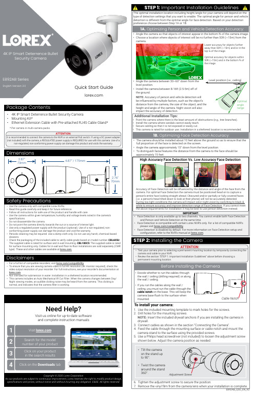
Quick Start Guide• Use the camera only with compatible Lorex NVRs.• Read this guide carefully and keep it for future reference.• Follow all instructions for safe use of the product and handle with care.• Use the camera within given temperature, humidity and voltage levels noted in the camera’sspecifications.• Do not disassemble the camera.• Do not point the camera directly towards the sun or a source of intense light.• Use only a regulated power supply with the product (optional). Use of a non-regulated, non-conforming power supply can damage the product and void the warranty.• Periodic cleaning may be required. Use a damp cloth only. Do not use any harsh, chemical-basedcleaners.• Check the packaging of the included cable to verify cable grade based on model number. CBL605U:The supplied cable is rated for surface and in-wall mounting. CBL100C5: The supplied cable is ratedfor surface mounting only. Cables for in-wall and floor-to-floor installations are sold separately (CMRtype). These and other cables are available at .Safety PrecautionsCopyright © 2020 Lorex CorporationAs our products are subject to continuous improvement, Lorex reserves the right to modify product design,specifications and prices, without notice and without incurring any obligation. E&OE. All rights reserved.• For a full list of compatible recorders, visit /compatibility.• To ensure that you are viewing camera video in full 4K resolution (4K monitor required), check thevideo output resolution of your recorder. For full instructions, see your recorder’s documentation at.• Not intended for submersion in water. Installation in a sheltered location recommended.• This camera includes an Auto Mechanical IR Cut Filter. When the camera changes between Day/Night viewing modes, an audible clicking noise may be heard from the camera. This clicking isnormal, and indicates that the camera filter is working.DisclaimersAdditional Installation Tips:Point the camera where there is the least amount of obstructions (e.g., tree branches).Install the camera where vandals cannot easily reach.Secure cabling so that it is not exposed or easily cut.This camera is rated for outdoor use. Installation in a sheltered location is recommended.1B. Optimizing Face Detection Accuracy:Angle the camera between 30~60° down from thelevel position.Install the camera between 8-16ft (2.5-5m) off ofthe ground.NOTE: Accuracy of person and vehicle detection willbe influenced by multiple factors, such as the object’sdistance from the camera, the size of the object, and theheight and angle of the camera. Night vision will alsoimpact the accuracy of detection.The optimal installation location including height/angle for your camera will depend on theThe camera should be installed about 10 feet above the ground so as to ensure that thefull proportion of the face is detected on the screen.Accuracy of Face Detection will be influenced by the distance and angle of the face from thecamera. For optimal Face Detection the camera must be positioned head on to capture aperson’s entire face looking straight ahead. Obscured and/or partially or fully covered faces(i.e. a person’s head tilted down to look at their phone) will not be accurately detected.During low light conditions the camera will impact color night vision by switching to black &white to ensure accuracy and improve detection range of Face Detection. If you cannot meetthe above requirements for installation it may be best to use person detection instead.IMPORTANT:Face Detection is only available up to two channels. You cannot enable both Face Detectionand Person and Vehicle Detection at the same time.Face Detection is compatible with certain Lorex NVR’s only. For a list of compatible NVR’s/compatibility.Face Detection is disabled by default. For more information on Face Detection setup andconfiguration, refer to the NVR’s manual at .Scenario 1: Connect Cameras to NVRScenario 2: Connect Cameras to Local Area Network (LAN)RouterCameraNVRRouterATTENTION:• This camera is only compatible with select NVRs. For a list of compatible recorders, visit /compatibility .You must connect the camera to a supporting H.265 NVR to take advantage of E892AB_QSG_EN_R2Use the Lorex app specified in your NVR documentation to activate two-way talk. Tap from the camera's live view, then speak into the microphone on your mobile device. Tap again when finished speaking.OR(Optional) 12V DC PowerEthernet CableUsing the RJ45 Cable Gland (Optional)A BUsing Deterrence FeaturesUse your Lorex app to manually activate the camera's white light and siren features when connected to a compatible Lorex recorder.PREREQUISITE: Connect to your Lorex system using the app specified in your recorder documentation.To activate deterrence features manually:1. Launch the app and tap your recorder to view connected channels.2. Tap a connected deterrence camera to open it in single-channel view.3. Tapto activate the white light, or tapto activate the siren.NOTE: You can also set schedules and active areas of the camera image where the white light will be triggered automatically when motion is detected. For full instructions, refer to the app manual on your product page at .These instructions are based on current NVR interface. For the most up-to-date instructions, .Select the format that will be used to record audio.。
医用动态数字化X射线透视摄影系统产品技术要求米视生物

1.性能指标1.1电功率1.1.1最大输出电功率摄影模式下(间歇方式):P=100kV×500mA = 50kW透视模式下(连续方式):P=125kV×6mA = 750W1.1.2标称电功率摄影模式下(间歇方式):P=100kV×500mA = 50kW 0.ls透视模式下(连续方式):P=125kV×6mA = 750W1.2加载因素及控制1.2.1X 射线管电压a)摄影管电压调节范围40kV~150kV,采用步进值为1kV 调节方式。
b)透视管电压调节范围40kV~125kV,采用步进值为1kV 调节方式。
c)X射线管电压的偏差应:≤±10%。
1.2.2X 射线管电流a)摄影管电流调节范围10mA~630mA,采用按R'10分档调节方式。
b)连续透视管电流调节范围0.5mA~6mA,采用步进值为0.1mA 调节方式。
c)脉冲透视管电流可设置范围10mA~30mA, 采用步进值为0.1mA 调节方式。
d)X射线管电流的偏差应≤±20%。
1.2.3加载时间a)摄影加载时间调节范围:1ms~10s,采用按R'10分档调节方式。
b)加载时间的偏差应≤±(5%+0.2ms);c)透视时间范围:5分钟后报警;10分钟后停止加载。
1.2.4电流时间积a)摄影电流时间积调节范围0.5mAs~800mAs,采用按R'10分档调节方式。
b)电流时间积的偏差应≤±(5%+0.2mAs)。
1.2.5点片摄影准备时间点片摄影准备时间应不大于1s。
1.2.6防过载应有防过载措施,保证加载因素的组合不会超过X射线的额定容量;应符合使用说明书中给出的最大加载因素组合。
1.3成像性能1.3.1摄影空间分辨率a)不加附加衰减体模状态下的空间分辨率应不小于3.7 Lp/mm;b)附加厚度2Omm纯铝衰减体模状态下的空间分辨率不小于3.4 Lp/mm 。
佳能MF4370dn-MF4350d-MF4330d-MF4322d-MF4320d service manual-CHN)维修手册

维修手册
MF4300 系列 iC MF4370dn/MF4350d/MF4330d/MF4322d/4320d
1-1
介绍
佳能 ( 中国 ) 有限公司技术部 BIS_TS 科发行
使用 本维修手册由佳能公司出版发行,供合格人员学习产品的技术理论、安装、维护和维修 . 本维修手册覆盖了产品的所有销售区域 . 正因为如此,本手册中可能含有并不适合您 所在地区的内容 .
将会以维修信息公告的方式进行交流 .
所有维修人员均应对本维修手册以及所有相关的维修信息公告板的内容进行深入的理
解和掌握,并且具有对设备故障进行识别、分析的能力 .
佳能 ( 中国 ) 有限公司技术部 BIS_TS 科发行
介绍
目录
目录
第 1 章介绍
1.1 产品规格................................................................................. 1- 1 1.1.1 部件名称 ........................................................................................1- 1
版权 本手册享有版权,保留所有权利 . 根据版权法,未经佳能公司的书面同意,本手册不得 全部地或者部分地复制、翻印、或者翻译为其他语言 . 版权所有 .2001 佳能公司
COPYRIGHT © 2001 CANON INC°£
警告
本手册的使用应该严密监督 ,以免泄漏机密信息
佳能 ( 中国 ) 有限公司技术部 BIS_TS 科发行
如在 “DRMD*”中星号表示当电平为” 0 ”时有 DRMD 信号通过 .
兄弟MFC-8460N_8860DN_DCP-8060维修手册

本手册的构成
本手册由9个章节和4个附录组成。
2.1.2.1 纸张操作................................................................................................. 2-2 2.1.2.2 介质规格................................................................................................. 2-2 2.1.3 可打印区域...............................................................................................................2-5 2.1.3.1 PCL5e/EPSON/IBM 㟩ਅ ...................................................................... 2-5 2.1.3.2 PCLXL, PS (BR-Script 3) ...................................................................... 2-8 2.1.4 各种设定下的打印速度...........................................................................................2-9 2.1.5 墨粉盒重量信息.....................................................................................................2-10 2.2 规格表 ............................................................................................................ 2-11
科视Christie GS 系列 长效 1DLP 激光投影机说明书

科视CHRISTIEGS 系列长效 1DLP 激光投影机董事室会议室教育场所政府现场活动舞台博物馆主题公园与旅游名胜宗教场所选择科视Christie® GS 系列作为您下一个项目的固态投影机,避免故障,减少更换灯泡和维护的成本。
从商业场所到现场活动等,专业级科视Christie GS 系列产品可为高使用环境带来卓越的性能和可靠性。
科视Christie GS 系列采用激光荧光体发光,可提供 20,000 小时低成本运行。
凭借无线连接、小巧外形、低重量、静音和全套镜头,GS 系列是董事室、会议室、教育、宗教场所、现场活动舞台和其他中小场所的不二之选。
我们的 850-GS 和 1075-GS 采用科视 BoldColor 技术并配备 1DLP® 激光荧光体,可带来更高的亮度和图像品质,呈现更加准确的色彩还原度。
长效激光投影机拥有成本较低630-GS 和 635-GS 仅限白色,中国地区仅限黑色。
850-GS 提供黑白双色。
1075-GS 仅限黑色。
技术参数科视Christie DWU630-GS科视Christie DHD630-GS图像亮度• 6750 ISO 流明(典型)• 6000 ANSI 流明(典型)• 6125 ISO 流明(典型)•5900 ANSI 流明(典型)• 5400 ANSI 流明(典型)色轮• 4 段(RGBY):2X 或 3X 速度对比度(全开/全关)•全开/关(启用科视Christie RealBlack™):4,000,000:1 • 动态对比度 6000:1• 全开/关(禁用科视Christie RealBlack):1200:1,ANSI 250:1显示技术类型• 单片 0.67" DMD S600HB标准分辨率• 1920 x 1200 (2,304,000 像素 ) (16:10)色彩控制• 拥有精确软件色彩调节,用于调节色调、饱和度和增益。
M500RTK华测产品介绍
产品介绍采用世界顶级主板——美国天宝主板,超强的解算引擎220个超级通用通道可全部接收GPS L1 C/A、 L2E、 L2C、L1/L2/L5 全周载波、支持GLONASS L1 C/A、L1 P、L2 C/A、L2 P、L1/L2全周载波、SBAS (MSAS/WAAS/EGNOS)信道、伽利略、北斗等卫星信号通道。
突出优势快速精确M500采用先进的多路径抑制技术可以大大提高GNSS实时动态初始化(OTF)速度,初始化可靠性可以达到99.99%以上,使M500的初始化更加快速精确,同时通过严密的卫星信号过滤技术选择信号最优的卫星组合方案来解算当前位置,为每一个测量点提供精确可靠的测量结果,快速达到测量精度,保证了测量的连续性和精度的均匀性。
国家认证高精度RTK水平精度:±(10 + 1×10⁻⁶×D) mmRTK垂直精度:±(20 + 1×10⁻⁶×D) mm完全一体化设计主机、天线、UHF、GPRS/CDMA、蓝牙、电池完全内置组成一个小型单元,100%无电缆。
CORS RTK内置专业的网络及电台通讯模块,成熟的网络数传技术和传统的UHF数据链技术兼备,可自由切换工作模式,网络方面完全兼容市场上所有的CORS系统,如天宝VRS、徕卡主辅站、拓普康CORS系统、FKP等。
DL5智能功放保护先进的功放管的保护功能及外接天线自动检测报警功能,解决了电台在使用过程中电台衰减导致距离近不能正常作业的现象。
真空显示屏在发射天线没有接好、没有连接,或者发射天线坏了等情况下可提示报警,可进一步识别问题所在,大大提高了电台的使用性能及寿命。
多馈点零相位中心天线部分采用多馈点设计,保证相位中心与几何中心的重合,将天线对测量误差的影响降至最低。
天线单元增益高,方向图波束宽,确保低仰角信号的接收效果,在一些遮挡比较严重的场合仍能正常收星。
带有抗多路径抑径板,有效降低多路径对测量精度的影响,避免带外强干扰引起放大器饱和,增加了系统的可靠性。
移动式G型臂X射线成像系统产品技术要求东方慧尔

移动式G型臂X射线成像系统产品技术要求东⽅慧尔移动式G型臂X射线成像系统适⽤范围:供医疗机构做⼀般X射线透视诊断使⽤。
1.1产品型号本技术要求覆盖的产品型号为B6、B6P和B6FD1.2 结构组成本设备由X射线发⽣装置(包括两套X射线管组件、逆变器组件)、X射线成像装置和附属设备(包括滤线栅、G臂机架、控制台、限束器、激光指⽰器、G臂转向刹车装置)三⼤部分构成。
本设备的选配件为打印机,选配功能为动态回放功能及引导线功能。
1.3部件规格参数1.4软件组件1.4.1 软件名称:G型臂⼯作站软件1.4.2 软件发布版本:V1.42.1⼯作条件2.1.1环境条件a) 环境温度:10℃~40℃;b) 相对湿度: 15%~70%;c) ⼤⽓压⼒:700hPa~1060hPa。
2.1.2 电源条件a) 电源:220VAC; 50Hzb) 电源容量:≥3kWc) 电源电阻:≤0.36Ω2.2电功率2.2.1最⼤输出电功率成像系统最⼤输出电功率:B6:1.65 kW(110kV、15mA,单路曝光); B6FD/B6P: 1.8 kW(120kV、15mA,单路曝光) 2.3 加载因素及控制2.3.1 X射线管电压2.3.2 X射线管电流2.4 防过载成像系统应有防过载措施,保证加载因素的选择不会超过X射线管的额定容量。
应符合使⽤说明书中给出的最⼤加载因素组合。
2.5 成像性能2.5.1间接透视成像性能a)在规定条件(70kV, 调节mA值直⾄图像清晰)下,系统的线对分辨率:不低于1.6Lp/mm ;b)在规定条件(70kV, 调节mA值直⾄图像清晰)下,系统的低对⽐度分辨率:不⼤于2%;c)在规定条件(70kV 3mA)下,影像增强器⼊射⾯空⽓⽐释动能率:应不⼤于10.0 µGy/s。
d)在规定条件(70kV 3mA)下,X射线机的⼊射空⽓⽐释动能率:应不超过50 mGy/min。
2.5.2医⽤X射线影像增强器电视系统成像性能a)有⽤⼊射野尺⼨:215±15mmb)影像失真:应不⼤于10%c)对⽐度范围:应不⼩于30。
7光谱成像技术
光谱图像分 像器
读出系统
计
算
机
读出系统
及
图
像
读出系统
处
理
系
读出系统
统
控制 电路
控制 电路
控制 电路
区 别�前者与后者相比有哪些特点�
2.光谱成像的类型�试写出凝视式光 谱成像的主要组成。
�光栅、滤光片、液晶可调滤光�LCTF�、滤 光阵列。
�按成像方式分类� a. 凝视式�一次仅记录一个窄的波长范围的影 像信息。
b. 扫描式�可以在空间上逐点扫描进行光谱分 析。
弹扫式光谱成像装置
推扫式光谱成像装置
推 扫 式 光 谱 成 像 装 置
摄像机参数表
型号 最高分辨率 像素尺寸 有效像素 传感器类型 传感器大小
分析光谱表明�为获取物质信息�在探测光谱的变化时 �对于探测仪器提出了光谱和能量两方面的探测能力的需求 。例如�探测叶绿素在0.8μm的"蓝移"�需要优於10nm的光 谱分辨能力�优於100�1的信噪比。在2.2μm附近的矿物质 �如高岭土类�探测�需要优於10nm光谱分辨率和50�1信 噪比。这些需求决定了遥感仪器性能参数的设计准则。
850线 >52dB 60dB 1.8V@550nm/lux/S ERS 60us-2s 外触发或连续采集
输出方式 可编程控制
USB 2.0
图像尺寸、亮度、增益、帧率、曝光 时间
镜头接口 功耗 供电 尺寸(W×H×D)
C口 <2.25W 5V 52X51X62(mm)或52X51X44(mm)
SGM200单光栅多色仪主要技术规格
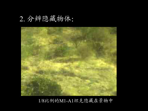
2. 分辨隐藏物体�
1/8比例的M1-A1坦克隐藏在景物中
- 1、下载文档前请自行甄别文档内容的完整性,平台不提供额外的编辑、内容补充、找答案等附加服务。
- 2、"仅部分预览"的文档,不可在线预览部分如存在完整性等问题,可反馈申请退款(可完整预览的文档不适用该条件!)。
- 3、如文档侵犯您的权益,请联系客服反馈,我们会尽快为您处理(人工客服工作时间:9:00-18:30)。
识读景深范围
尺寸与规格
USB接口 电源开关
机械结构图
机械结构
外形尺寸:59.9 mm×37.6 mm×13.9mm 重 量:50g
电气特性
电 源:DC5V±5% 解码功耗:150mA @ DC5V 启动时间:< 100ms
支持码制
ቤተ መጻሕፍቲ ባይዱ
电源管理
连续解码续航能力:
扫描器电池 容量:750mAh 手 柄电池容量:900mAh 待 机 时 间: 15天
手持手柄:可配备续航能力强大的手柄(手柄内置电池可换)
科技园1号楼B座1603室
移动 背夹:用于将扫描器固定在所有的移动设备上(手机,平板电脑) 电话: 022-58625723
传真:022-58625724
蓝牙适配器:为PC增加蓝牙功能
邮编: 300384
网址:
内置电池支持全天大数据量扫描;
不但支持各种条码介质,而且支持直接的 屏幕扫描;
云扫描服务是Genealscan 依据物联网 3i 概念--感知、互联、智能 率先设计出来的物联网服务,它将采集到 的数据,通过云同步和数据智能挖掘手段, 实现采集数据的跨平台共享和传输;
可灵活附着在各种移动设备上,随用户 移动到任何工作区域;
GS-M500BT 搭载Generalscan云扫描服务,使您的智能移动设备成为专业的条形码数据采 集终端。它可以固定在智能移动设备上,借助蓝牙传输方式与移动设备通信网络,实现随时随地
扫描,极大的提高了您工作的机动性。
采用Generalscan 自主研发的条码扫描 核心技术,将无线扫描器的尺寸极致压缩 至打火机大小,便于携带; 采用高分辨率CMOS传感器,无运动 部件,提高产品的寿命和可靠性; 良好的反应速度,TTR< 30ms,(详见TTR 说明文档) ; 采用蓝牙通信技术,可方便灵活地连接具 有蓝牙功能的设备,提高工作的机动性;
GS-M500BT
二维云条码扫描器
GS-M500BT 是一款拥有超小型成像系统的蓝牙二维条码云扫描器。它采用先进的解码技术, 提供最佳的识读能力,可轻松地读取一维、二维条码。GS-M500BT优越的性能、卓越的阅读能力 来源于Generalscan独有的DynaExpo的算法。它可广泛的应用于医疗设备、电子装配、零售业、 银行自动存款机等多个领域中。
支持具有iOS、Android、Windows 等主 流操作系统的手机、平板电脑和PC;
保证用户在离线情况下,快捷的配置扫 描引擎参数,使扫描引擎快速进入工作 模式。
医疗服务、条码支付、快递物流、仓储 货运、产品追溯、生产管理、图书管理、 资产管理、商场超市等行业均可使用;
更多产品信息请登录: 云服务详情请登录:
设备组合 扫描器
连续触发扫描间隔 解码次数或时间
1秒
20000次
5秒
7-8小时
质保期
具体测试条件请详询Generalscan
扫描器保修一年,电池保修半年,提供终身维修
通讯方式
蓝牙无线电通信技术(10米以内)
通用串行总线(USB2.0)
配件
USB线缆:用于充电和数据通信
天津物联传感科技有限公司
Tianjin Generalscan IOT Technology Co.,Ltd 地址:天津市南开区华苑产业园区榕苑路15号鑫茂