bhk-3000使用说明书
JBK3000变电站综合自动化系统保护测控装置技术使用说明书要点

1)20路遥信开入采集、装置遥信变位、事故遥信;2)正常断路器遥控分合、小电流接地探测遥控分合;3)IA、IB、IC、I0、UA、UB、UC、UAB、UBC、UCA、U0、P、Q、 、f等15个模拟量的遥测;4)开关事故分合次数统计及事件SOE等;6)1路GPS校时(具有秒/分脉冲、IRIG-B(DC)码校时功能);7)配有一个CAN、一个RS485和两个LAN接口,接口带有光电隔离。
ADD:NO.22,Dacisi Road,Che务联系电话/TEL:028-86763579
电话/TEL:028-86763574 86763575 86763576
售后服务及技术支持电话:028-86763572
028-86763574/701/702
传真/FAX:028-86763573
第一部分
JBK3000
变电站综合自动化系统
系统概述
JBK3000变电站综合自动化系统系统概述
一.1
JBK3000变电站综合自动化系统是成都智达电力自动控制有限公司在总结多年来服务电力系统自动化领域基础上,充分认识变电站现场应用情况,集合强大的保护功能和测控功能,保护和测控功能既相对独立又相互融合,为变电站综合自动化提供了一个完整的解决方案,能满足110kV及以下变电站的综合自动化需要。
JBK3000变电站综合自动化系统是在总结多年来服务电力系统自动化领域基础上,充分认识变电站现场应用情况,集合强大的保护功能和测控功能,保护和测控功能既相对独立又相互融合,为变电站综合自动化提供了一个完整的解决方案,能满足110kV及以下变电站的综合自动化需要。它集电力系统、电子技术、自动化、继电保护之大成,采用分散、分层、分布式结构实现面向对象的思想,优化系统功能,利用高性能单片机构成的数字智能电子设备和计算机主机代替了数据量大、功能结构单一的继电器、仪表、信号灯、自动装置、控制屏。在遵循数据信息共享、减少硬件重复配置的原则下,做到继电保护相对独立并有一定的冗余,提高了变电站运行的可靠性,减少了维护工作量并提高维护管理水平。
3000KW背压机汽轮机操作规程

第一章汽轮机主要技术规范第一节主要技术数据第二节调节保安润滑系统第三节整定值第四节主要辅助设备第二章汽轮机操作规程第一节启动前的准备工作第一条:班长或主操在接到汽轮机组启动的操作命令后应:1.通知副司机及其它岗位有关运行人员。
2.领导进行启动前的一切准备工作和启动汽轮机的各项操作,通知启动的时间及从暖管开始后的各项操作记录在运行日志中。
第二条:值班运行人员在启动前应对全部设备进行详细检查:1.首先应检查所有曾经进行过检修工作的地方,肯定检修工作已全部结束,工作票已注销,汽轮机本体、各附属设备及周围场地清扫完毕。
2.油管、油箱、冷油器、油泵等均处于完好状态,油系统的任何地方均无漏油现象。
3.肯定油箱油位正常,油质良好,油位计的浮标上下灵活,开启排污放水后严密关闭。
4.检查危急保安器、轴向位移继动器、磁力断路油门均处于断开状态,主汽门、电动隔离门及旁路门处于关闭状态。
5.调速汽门连杆、各螺丝销子等装配完好,各活动支点处油标均注满润滑油,手拉油动机拉杆活动自如。
6.检查同步器在低限位置,调压器伸缩筒内己注满蒸馏水。
7.检查汽轮机滑销系统,记录汽机膨胀始点值。
第三条:通知电气、热工人员送上热控系统电源,检查各测量指示仪表均处于完好状态,各仪表阀门均处于开启状态,会同电气运行人员试验联系信号及同步器增减方向。
第四条:检查各系统阀门处于开启或关闭状态。
1.会同热工人员对电动隔离门进行手动、电动开关检查,正常后关闭﹙检查前应确认隔离门前无压力,隔离门前疏水开启﹚。
2.主蒸汽、排汽管道上的电动隔离门、手动隔离门、主汽门关闭,对空电动排汽门开启。
3.排汽管道疏水门、本体疏水门开启,前后轴封漏汽疏水门开启。
4.冷油器进水总门开启、冷油器进水门关闭,出水门开启,冷油器进出口油门开启,备用冷油器进出口油门关闭。
5.轴封加压器疏水门开启。
6.交流油泵进出口门开启。
7.直流油泵进出口开门启。
第五条:下列情况下,禁止汽轮机启动或投入运行:1.交流油泵、直流油泵工作不正常时;2.危急保安器动作不正常、主汽门、调节器动作不正常,有卡涩现象时;3.调速系统不能维持空负荷运行和甩去全部负荷后不能控制在危急保安器动作转速以下时;4.危急保安器、危急遮断油门、轴向位移遮断器、磁力断路油门工作不正常;5.缺少转速表或转速不正常;6.机组振动超过0.07mm时;7.油压、油温不符合规定值;8.盘车发现有不正常声音时;第六条:汽轮机具备启动条件后,班长或或司机向主管报告并通知锅炉运行人员准备暖管。
HB-3000布氏说明书解析
HB-3000型布氏硬度计用户使用手册莱州华银试验仪器有限公司(原山东掖县材料试验机厂)硬度是金属材料及合金材料机械性能的重要指标,通常指的是一种材料抵抗另一较硬的具有一定形状、尺寸并且本身不发生残余变形的物体压入其表面的能力。
HB-3000型布氏硬度计可用于测定未经淬火钢、铸铁、有色金属及质地较软的轴承合金等的布氏硬度值;适用于厂矿、科研单位和大专院校试验室。
布氏硬度试验是把一定直径的淬火钢球以规定的负荷压入试样表面经规定的保荷时间后卸除负荷,测量试样表面的压痕直径(见图1),计算出布氏硬度值。
改值以试样压痕表面积上的平均压力(公斤力/毫米2)表示(见表1)。
用式(1)计算:布氏硬度=0.102*)(222d D D D F--π……………… (1) 表1 符号及名称符号名称 单位 D硬质合金球直径 毫米 F试验力 牛顿 d压痕平均直径 毫米 d 1,d 2在两相互垂直方向测量的压痕直径 毫米 h压痕深度 毫米 HBW 布氏硬度错误!未指定书签。
图1 布氏硬度试验原理图对一定直径的硬质合金球施加试验力压入试样表面,经规定保持时间后,卸除试验力,测量试样表面压痕的直径,见图1。
示例:350HBW5/750 表示用直径5mm 的硬质合金球在7.355KN 试验力下保持10s-15s 测定的布氏硬度值为350.*本节“试验原理”的内容参考中华人民共和国国家标准《金属布氏硬度试验》(GB/T231.1-2002)概述 试验原理 产品介绍布氏硬度试验最常用的标准条件是硬质合金球压头为10毫米(见图2)、负荷为3000公斤力,此时最能体现布氏硬度的特点。
但是,由于试样的软硬不同、大小不一,一种负荷、一种钢球是不能满足的。
对于同一试样,采用不同直径的钢球及不同的负荷,要得到相同的硬度值;或者说要获得可以比较的结果,只有在负荷与钢球直径的平方之比为一常数时才可能(见表2)。
表2 布氏硬度试验钢球直径和负荷选择表负荷F 与钢球D 2之比 钢球直径D 硬度范围 (硬度值)适用对象 10 5 2.5 1.251 30 3000 750 187.5 46.9 30.0 140-(945) 钢、灰口铸铁、铝 10 1000 250 62.5 15.6 10.0 48-3155 500 125 31.2 7.8 5.0 23.8-158 退火铝2.5 250 62.5 15.63.9 2.5 11.9-79 轴承合金1.25 125 31.2 7.82.0 1.2 6.0-39 导线0.5 50 12.5 3.1 0.8 0.5 2.4-15.8 柔软材料图2硬质合金球压头主要技术参数见表3、图3表3主要技术参数项目(代号)内容高度(H )842毫米 宽度(W )268毫米 长度(L )700毫米 试件最大高度(带保护套)(B )230毫米 压头中心至机壁距离(A )120毫米 硬度计净重210公斤 硬度单位试验力级数(kgf ) 硬质合金压头(mm ) 布氏 187.5 250 750 1000 3000 2.5 5 10 技术参数 适用范围图3 外形尺寸示意图机构部件简述本硬度计属杠杆硬度计结构,这种硬度计体积小,便于使用,广泛应用于生产一线,其结构见图4本硬度计主要包括升降部件,主轴部件,杠杆系统,减速器部件,换向开关部件组成。
bhk-3000使用说明书

退出休眠状态或停附属小泵相对压力
单位:Mpa
在休眠状态(包括小泵变频工作时休眠)下或小泵变频工作时,当前压力低于 设定压力(小泵变频工作时为Pr02的值)-Pr28时,退出休眠或退出小泵
密匙组
Pr29
密码1
0--99
55
Pr30
密码2
0--99
55
Pr31
密码3
0--99
55
Pr32
可工作天数
4、常用接线原理图
标准四台泵循环软启动方式原理图(以三垦变频器为例,见附页)。
五、参数及说明
参数
功 能
参数范 围
出厂设 置
说明/注释
压力设定组
Pr00
设定压力1
单位:MPa
Pr01
设定压力2
单位:MPa
Pr02
设定压力3
单位:MPa注:小泵变频工作时, 其压力设定为本参数
Pr03
超压设定值
单位:MPa
B1—B4
变频泵控制输出,容量5A, 接交流220V接触器。
D1—D4
工频泵控制输出,容量5A, 接交流220V接触器。
D5
附属小泵控制接点,容量5A, 接交流220V接触器。
PE / N / L
AC220V电源,PE为接地端。
3、与常用变频器的连接
富士
西门子
三星
台达
三肯
松下电器
明电舍
ABB
D/A
12
3
11
AVI
VRF
FIN
FSV
AI1
G
11
4
9
ACM
ACM
G
COM
AGND
HB-3000布氏硬度计

√ √ √
√
√
√
√
√
√ √
9.807KN (1000Kgf)
29.42KN (3000Kgf)
√
√
√
√
√
将全部砝码挂上
试验
1.试验一般在10~35°C室温下进行。对于温度要求严格 的试验,温度为23±5°C。 2.根据试样金属类型、硬度范围及厚度按表1选择压头 (球直径)及试验力。 3.放置试样:试样应稳固地放在试台上,试样背面与试台 面之间应清洁。 4.转动手轮上升试台1,使压头与试样接触至手轮与丝母 产生相对滑动。 5.试验力保持时间:根据表1所列类型,选择好试验力保 持时间后,将螺钉松开,把圆盘的弹簧定位器旋转至所需 的时间位置上(注意:此时螺钉处于松开状态,不可拧 紧)。
3.试样厚度至少应为压痕的8倍,试样最少 厚度与压痕平均直径的关系参见上表
试验力组合
产生的力值 大小 杠杆 613N (62.5Kgf) 1.839KN (187.5Kgf) 2.452KN (250Kgf) 7.355KN (750Kgf) 将吊架 挂在大 杠杆上 砝码组合(Kg) 62.5 500 250
hbhb30003000型布氏硬度计图片型布氏硬度计图片布氏硬度计概述布氏硬度计概述金属布氏硬度试验是采用一定直径的球金属布氏硬度试验是采用一定直径的球钢球或硬质合金球硬质合金球以规定的试验力压入试样表面以规定的试验力压入试样表面经经规定保持时间后卸除试验力测量试样表面规定保持时间后卸除试验力测量试样表面的压痕直径计算试样上球压痕面积所承受的平的压痕直径计算试样上球压痕面积所承受的平均压力
检验和保养
1.指示误差的检验:用随机携带的标准布氏硬度块,按硬度块上的 定度条件,在各定度点附近测三点,计量其算术平均值,该平均 值和标准布氏硬度块标称值之比应不大于3%。 即: H- H)/ H*100% 式中:H——-3点的硬度平均值 H——标准硬度块的值 2.球的检验:定期对球的表面粗糙度及圆度进行检验。其表面粗糙 度不应大于Rz0.2um。圆度误差D10mm球应小于5um;D5mm球应 小于4um,D2.5mm球应小于3um。 3.手轮定位器的检验:取下大吊架和压头,转动手轮使试台上升并 接触主轴端面,继续转动手轮,大杠杆被顶起,保荷指示灯(绿 色)亮。将吊架轻轻挂在大杠杆上,此时保荷指示灯熄灭,转动 手轮,当手轮与丝母产生相对滑动时,保荷指示灯(绿色)不亮。 此种状态试件与主轴所产生的压力是大于612.9N(62.5kgf)而小于 1839N(187.5kgf),定位器合格。 4.其它:硬度计试验完毕时,试台台面及球面表面应涂除锈油,以 防锈蚀。砝码应从吊架上取下。丝杠及螺母应定期注入润滑油。
KH-3000中文操作手册 latest edition VER.1.0 BETA

第五章测量样品J测量窗口 100J校准 102 设置新标度 102标度应用 105标度编辑 107标度删除 108标度保存 109标度读取 110标度表 111 J测量 112 距离 112面积 138角度 140计算 143快捷菜单 148测量数据的确认 160 J工具功能 167 文本设置 167网格线设置 168标尺设置 168日期设置 169选项设置 170打印 171保存数据 172KH-3000V/KH-3000VD用户手册99KH-3000V/KH-3000VD用户手册100在菜单(MENU )中点击测量(MEASUERMENT )。
在测量窗口中有2种图标:测量图标,可以计算目标的长度、面积、角度等等;工具图标,可以改变屏幕的显示内容等等。
测量图标工具图标测量图标KH-3000V/KH-3000VD用户手册101工具图标KH-3000V/KH-3000VD用户手册102校准为了获得精确的测量数据,必须预先校准标尺KH-3000可以存储30个标尺数据,这些已记录的标尺同样可以存储在记忆卡里。
什么是标尺?当测量样品的尺寸时,是根据相距的像素来计算的,而像素的尺寸会随放大倍率的改变而改变,因而要得到观测目标的精确尺寸,必须在测量前先设定标尺。
设定一个新标尺根据不同的镜头类型、放大倍率来设定标尺数据和单位,这些数据可以被存储在数据库中。
设置数据 说明NO 显示已设定标尺的编号PIX 在标尺设定屏幕上显示像素数目,当点击PIX 时,一个数字键盘会显示,改变所需要的像素数目,标尺的长度会根据像素数目的改变而改变,(从1到1600,出厂设置为50)LENGTH在标尺设定屏幕上显示像素数目,当点击LENGTH 时,一个数字键盘会显示,改变所需要的像素数目,标尺的长度会根据像素数目的改变而改变,(从0.001到9999.999,出厂设置为50)UNIT 选择和设置数值单位,(出厂设置为pix ,inc ,mm ,cm ,μm 和nm ) H VIEW 在屏幕上显示水平视图距离,数值会被自动计算,这个计算数值不能被改变 1 PIXEL 显示已标定的像素,数值会被自动计算,这个计算数值不能被改变 NOTE 设定标尺数据的备注,最多可输入24个字符1. 在菜单中点击测量MEASUREMENTKH-3000V/KH-3000VD用户手册103显示测量窗口显示标尺说明如果您知道像素的精确尺寸,可以点击Numerical 输入数值显示标尺设置屏幕在标尺调节中点击鼠标右键,显示快捷菜单。
BK3000可燃气体报警控制系统操作及使用说明书

键和 Enter/自检键组成。
序号 键名
功能描述
备注
1
ESC
非主界面下用于退出当前界面,返回到上一级菜单
2 消音键
火警报警发生时按此键即被消音 故障报警发生时按此键即被消音
3 复位键
主显示界面下按此键进入复位界面
4 左键
非主界面下用于删除 非主界面下用于更改、编辑选项
5 菜单键
主显示界面下按此键进入菜单界面
体探测器(以下简称“探测器”)和 NFB700-BK3001Ex 接收器为探测主体、以
NFB700-BK3002Ex 执行器为执行主体,共同组成了智能化的可燃气体报警及联动控制系统。
2、系统组成
可燃气体报警控制系统图 3、控制器部分 3.1、产品概述
控制器完全符合GB16808-2008 《可燃气体报警控制器》的要求,用于检测环境空气 中待测气体的浓度,可挂接多种类型的气体探测器、执行器、接收器(以下简称“编制单 元”),可以实现对多点进行集中控制。当环境中检测到待测气体的浓度达到或超过预置 报警值时,控制器立即发出声光报警,提醒用户及时采取安全措施,并启动执行器来控制 驱动排风或其它外设设备,防止中毒事故、爆炸、及火灾发生,从而保障生命、财产的安 全。本系统人机接口采用液晶显示和键盘交互操作,中英文界面显示,操作简单,可实时 显示现场气体浓度值。本机特有的软件抗干扰技术、机器故障软检测方式,使得设备高效 稳定的运行。 3.2、主要技术参数 * 环境温度: -10℃~+55℃ * 相对湿度:0~95﹪RH(无凝露)
主电正常工作时点亮。
4
备电指示灯 绿色
备电正常工作时点亮。
主电故障时被点亮,故障排除后熄灭。 5 主电故障指示灯 黄色
SBK TwinCo 3000 配水站 操作手册说明书

Version 9211/bOperating GuideSBK TwinCo 3000 distribution stationSiegfried Böhnisch Kunststofftechnik GmbH Maybachstraße 1 D-74632 Neuenstein Tel +49(0)7942-944 926 0 Fax +49(0)7942-944 926 99 **********************www.sbk-neuenstein.deF o r m 60e n g lTable of contentsTechnical data (3)SBK Tempus control overview (4)Thermal functionality SBK TwinCo 3000 (5)Electric connection SBK Tempus control (6)Service and modes of operation (8)Outside temperature controlled flow temperature setting diagram (9)Constant flow temperature setting diagram (10)Function of the rotary knobs SBK Tempus control (11)Introduction (12)Mistake removal (14)Introduction security sheet (15)Appendix individual parts cultivation sentence (17)Appendix electric connection (17)Accessories (18)Notice (19)Version 9211/bSeite 2Technical DataSuitable for floor surfaces to max. 1,200 l/h (approx. 28,800 kJ) with completely open throttle valve.The connecting pipe is laid out for:• Preliminary heat temperature heating system: min + 70°C• Preliminary heat temperature floor: + 20°C to + 50°C• Middle temperature difference: 6 ° to 8 ° K and approx. 75 W/m ² Pump data:• Wilo RS 25/6-3• If 6 m nominal conveyor correspond with Q = 0 m ³ / h• Speed area 1.100 - 2.200, 1 / min• 3 speed steps (achievement admission 46/67/93 W)• Protective kind IP 42• Sound pressure level recorder according to German Institute for Standardization 45635 to max. 34 dB (A)Regulator data:• Connection tension 230 V ~, 50 hertz• Achievement admission 1.5 VA• Protective kind IP 42• Surroundings terms: – 20°C to + 50°CControl valve:About the control valve the required quantity of water (warm amount) is supplied to the floor circulation to reach the desired preliminary heat temperature.Throttle valve:The quantity of water which should flow in by the control valve onto the floor circle can be limited by the fine regulating spindle in the throttle valve. The volume stream from the secondary circle of the floor system in the primary circle of the heater arrangement flows back and becomes braked. Thereby becomes the raised assembly line speed which arises from the addition of the primary pump pressure and the secondary pump pressure, reduces again. Security temperature limiter:The arrangement is equipped with a security temperature limiter which switches off the complete arrangement at a floor preliminary heat temperature> 60°C.Pump:The secondary pump becomes with the modes of operation• Steady preliminary heat temperature• Preliminary heat temperature as a leadership sizewhen long term runners pursued. A combination with the control distributor with integrated pump switch off modul (option kind no.:6.013.048.030) allows a regulated disconnection of the control and therefore also of the pump and is to be advised for the lengthening of the life span of the pump and the energy conservation.To the avoidance of hydraulic problems we recommend the additional installation of hydraulic points.Version 9211/b Seite 3SBK TEMPUS CONTROLOverviewTempus is a modern digital controller which combines the simple operation known from normal analogue devices with the precision and wide-ranging functions of a digital device.• Tempus controls the flow temperature based on the outside temperature with automatic limitation of the maximum flow temperature.• Tempus can also be used as a fixed value controller, i.e. the set flow temperature is adhered to precisely (standard model).• Tempus controls valves to set the afflux. The valves open and close slowly (approx. 5 minutes). The controller is optimal for use with underfloor heating.Integrated safety functionsIn addition, Tempus has numerous integrated safety functions to protect the system.• Safety temperature limitationEvery heating system should be secured by a double safety function, therefore a safety thermostat (safety temperature limiter) has also been integrated in addition to the safety functions of the controller to limit the maximum performance of the heating system.• Anti-block logic for the pumpWhen the system is controlled by the outside temperature or boiler temperature, the pump switches off as soon as the outside temperature is approximately 1 °C higher than the set room temperature (control knob B). The pump is switched back on again as soon as the outside temperature drops approximately 2 °C below the set room temperature.If the outside temperature is higher than the room temperature for a longer period of timee.g. in the summer, the pump is switched off and only switched on again for a short periodat fixed intervals to prevent the pump from getting stuck.If control knob C is turned to OFF, this function is activated automatically.• Anti-blocking logic for valveThe valve is also switched on for a short period of time in the same way as the pump is in order to prevent it from getting stuck.• Failure of a sensorIf the outside sensor is missing or has failed, the system automatically switches into the “constant flow temperature” mode.If the flow sensor is missing or has failed, the valve is controlled with the opening half open and therefore a basic heating is established for safety reasons.Version 9211/bSeite 4Version 9211/bSeite 5Thermal function of the SBK TwinCo 3000The well know principle of heating circuit distribution for underfloor heating made up of flow distributor and return distributor is supplemented by a control valve and a pump.Fig. 1: TwinCo 3000Warm heating water flows from the flow distributor through the underfloor heating pipes – during which it cools down – and then into the return flow distributor. Here it is mixed with the warm heating water from the heat generator (boiler, gas circulator) and then pressed back into the flow distributor by a pump. This pump also serves as the transport pump of the water in the underfloor heating circuit. The volume of heating water coming from the heat generator is controlled by a valve. However, in this particular case, the boiler flow is connected to the underfloor distributor return flow and the boiler return flow is connected to the underfloor distributor flow. The control valve is positioned in front of the supply line of the underfloor return distributor beam (see diagram).SBK Tempus controls the pump and the valve which influences the flow of heating water into the return flow distributor. If the required flow temperature has not been reached, the valve is opened. If the required flow temperature is exceeded, the valve is closed. The valve opens and closes slowly in small steps.The required flow temperature is set either by selecting the flow temperature using control knob “C” (see page 4) or by calculation using the current outside or boiler flow temperature. .Version 9211/bSeite 6Installation and connectionThe system is installed and connected according to Fig. 2. The electrical connection must be made by a qualified electrician and he will also be responsible for ensuring that the safety regulations are adhered to as required by the current stand of technology.The outside sensor (special accessories) should be fitted in a protected place facing north. The cross-section of the cable connecting the sensor to the controller is not important.Fig. 2: Connecting diagramTerminal allocationVoltage supply 230 V L1, N, PE Safety temperature limiter L1,0 Pump N,1,PE Actuator for control valve N,2 Flow sensor underfloor heating circuit 50,51Outside temperature controlled flow temperatureVoltage supply 230 V L1, N, PE Safety temperature limiter L1,0 Pump N,1,PE Actuator for control valve N,2 Flow sensor underfloor heating circuit 50,51 Outside temperature sensor (optional) 52,53 In case of this operating mode it requires the Outside temperature sensor(ArtNo.: 6.013.074.050)Fig. 3 TwinCo 3000 with outside temperature sensorBoiler controlled flow temperatureVoltage supply 230 V L1, N, PE Safety temperature limiter L1, 0 Pump N,1, PE Actuator for control valve N, 2 Flow sensor underfloor heating circuit 50, 51 Flow sensor for boiler temperature (optional) 54, 55 In case of this operating mode it requires theBypass(OrderNo. 6.013.074.070)sensorsupply(Order No.: 6.013.074.051)Fig. 4: TwinCo 3000 with supply sensorVersion 9211/b Seite 7Version 9211/bSeite 8Operation and operating modesThe controller SBK Tempus can work in three different modesLED1 control networkLED 2 operating modeFig. 5: Operating panel of the control unitConstant flow temperatureIf it controls an additional heating system, in the bathroom or conservatory, the floor should always have a constant temperature. An outside sensor may not be connected for this operating modeControl knob A has no function (do not turn all the way to the right) Control knob B has no function (do not turn all the way to the right) Control knob C is used to set the required flow temperatureClimate controlled or outside temperature controlled flow temperatureThe heating curve is set in accordance with the planning documents. In compliance with DIN 4701, the planning data is always based on a room temperature of 20°C at an outside temperature of –15°C.Control knob A is used to set the calculated flow temperature (diagram 1 page 7) Control knob B is used to set the required room temperatureControl knob C is used to set the maximum admissible flow temperature.ATTENTION: The set temperature must be higher than the temperature set at control knob A.Boiler controlled flow temperatureThe heating curve is set in accordance with the planning documentation. The data is always based on a room temperature of 20°C at a boiler flow temperature of 70°C.Control knob A is used to set the calculated flow temperature (diagram 2 page 8) Control knob B is used to set the required room temperatureControl knob C is used to set the maximum admissible flow temperature.ATTENTION: The set temperature must be higher than the temperature set at control knob A.Special operating modePump test mode: Control knob A must be turned all the way to the right, the pump is switched on, the valve is switched off.Valve test run: Control knob C must be turned all the way to the right. Both the pump and the valve are switched on.Switching off pump: Control knob C must be turned all the way to the left, the pump is switched off (summer mode: function anti-block logic for pump and valve is active).Version 9211/bSeite 9Settings of control knob A for outside temperature controlled operating modeFig. 6: Diagram 1 heating curve for operation controlled by outside temperatureThe heating curve is set in accordance with the planning documentation. According to DIN 4701 the planning data is always based on a room temperature of 20°C at an outside temperature of – 15°C.Control knob A in position 1Calculated flow temperature 20°C at an outside temperature of –15 °C and 20°C room temperatureControl knob A in position 3Calculated flow temperature 33°C at an outside temperature of –15°C and 20 °C room temperatureControl knob A in position 5Calculated flow temperature 48°C at an outside temperature of –15°C and 20 °C room temperatureControl knob A in position 7Calculated flow temperature 60°C at an outside temperature of –15°C and 20 °C room temperature.Version 9211/bSeite 10Settings of control knob A for boiler temperature controlled operating modeFig. 7: Diagram 2 heating curve for operation controlled by boiler flow temperatureThe heating curve is set in accordance with the planning documentation. The data is always based on a room temperature of 20°C at a boiler flow temperature of 70°C.Control knob A in position 1Calculated flow temperature 20°C at an boiler flow temperature of 70 °C and 20°C room temperatureControl knob A in position 3Calculated flow temperature 29°C at a boiler flow temperature of 70°C and 20 °C room temperatureControl knob A in position 5Calculated flow temperature 38°C at a boiler flow temperature of 70°C and 20 °C room temperatureControl knob A in position 7Calculated flow temperature 47°C at a boiler flow temperature of 70°C and 20 °C room temperature.Function of control knobsOperating mode based on climate or outside temperature controlledThis control knob is used to set the heating circuit flow temperature which is to be realized by the control system according to the design of the heating system (DIN 4701)Together with control knob B is it used to calculate the heating curveSpecial functionTurn the control knob all the way to the right, pump starts up, valve remains closedThis control knob is used tospecify which required set value temperature is to be realized.It is used to calculate the heating curve together with control knob A.Special function:Turn the control knob all the way to the right, Outside temperature sensor/ supply sensor has no functionThis control knob is used to set the maximum permissible flow temperature for the heating circuits.Attention: The set temperature must be higher than thetemperature set using control knob ASpecial function:Turn control knob all the way to the right. Pump is activated. Valve is opened. Turn the control knob all the way to the left.Pump is switched offOperating mode constant flow temperatureControl knob does not have a functionSpecial functionTurn the control knob all the way to the right, pump starts up, valve remains closedControl knob does not have a functionSpecial function:Turn the control knob all the way to the right, Outside temperature sensor/ supply sensor has no functionUse this control knob to set the permissible flow temperature for the heating circuits.Special function:Turn the control knob all the way to the right. Pump starts up, valve is opened.Turn the control knob all the way to the left.Pump is switched off.Attention: Never turn all three control knobs all the way to the right at the same time whilst the system is operational, as otherwise an internal test function is inadvertently activated which can lead to faults with the control unit.Calibration for sensor BEC-UNISENS1Outside temperature sensor, supply sensor for SBK TwinCo 3000 distribution station65Technical data IPTemperature range-40 °C up to 70 °C°C kΩΩTemp °C kΩΩ Temp40 10,14 10148,00-20 229,31 229310,00- 15 169,02 169020,00 45 8,20 8205,3012850,00 50 6,67 6672.60 -10 125,85,44 5448,6055 5-5 94,15 94153,0060 4,47 4473,900 71,12 71126,0065 3,69 3691,805 54,23 54237,0070 3,06 3060,9010 41,71 41719,0075 2,55 2551,0015 32,40 32409,0080 2,13 2135,5020 25,36 25367,00i 85 1,79 1798,6025 20,0020000,0090 1,52 1521,4030 15,88 15884,0095 1,29 1290,5035 12,65 12654,001098,801,09100Appendix SBK TwinCo 3000 individual parts9Flat packing2 10Union nut2 11Pump1 12SBK HKV 3000 return flow segment DFM 1771 13Locking cap 3/4”2 14SBK controle valve1 15SBK actuator 230V~1 16Bypasspipe 16x2 MSV-pipe 1 With connections17Filling and drain valve1Notice:。
迈克尔·朗登·3000型号电子旋转筛子商品说明书
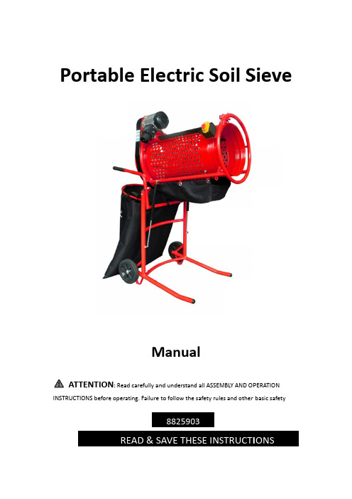
PINSTPortATTENTTRUCTIONS btableTION: Readbefore operaREe EleMd carefully aating. FailureEAD & SectrManuand understae to follow th88259SAVE THic Soalnd all ASSEMe safety rule03HESE INSoil SMBLY AND OPes and otherSievePERATIONbasic safetyIONSeTable of ContentsSafety Notes (2)Symbol Explanation (3)Before first Use (4)Intended Use (4)Assembly (5)Hints for Using (6)Maintenance (7)Replacing the Drive Belt (7)Cleaning and Storing (7)Technical Data (9)Overview (10)Safety NotesPlease note the included General Safety Notes and the following safety notes to avoid malfunctions, damage or physical injury:●Make sure the voltage corresponds to the type label on the unit.●Never leave the rotary sieve unsupervised when in use. Keep out of reach of children orpersons in need of supervision.●Persons with limited physical, sensorial or mental abilities or lack of know‐how and/orlack of knowledge are not allowed to use the unit, unless they are supervised andbriefed for their safety by a qualified person.●The rotary sieve is designed exclusively for sifting compost, soil and clumped sand. Donot use the rotary sieve for purposes for which it is not intended.●The rotary sieve is designed for operation under ambient temper‐atues between +5° Cand +40° C. The surrounding humidity should be less than 50 % at a temperature of +40°C. The rotary sieve can be transported and stored under ambient temperaturesbetween ‐ 25° C and +55° C.●Do not wear any loose clothing or jewelry. These can get caught up in moving parts.Non‐slip footwear is recommended if working out of doors. Wear a hair net if you have long hair.●Do not grasp into the moving drum or other moving machine parts.●Make sure all parts are securely mounted before switching on machine.●Never try to stop moving parts by hand.●Check all movable parts to ensure that they are still functioning perfectly and incompliance with specifications. The rotary sieve must be connected properly and fulfill all requirements in order to ensure perfect operation of the machine. Make sure that the machine stands stable on firm ground.●Only use original spare parts from Princess Auto.●Please switch off the unit and unplug from the power supply before cleaning,maintaining or when not in use.●When filling soil into the drum keep the shovel or garden fork clear of the drum andmake sure the shovel or garden fork cannot become jammed. There is risk of injury.●Switch off the rotary sieve during rest brakes.●Do not operate the machine if it does not work correctly or has been damaged.●Do not operate the rotary sieve on inclined surfaces. Always take care the machine isstanding as horizontally as possible.●In case of operating the machine on slippery surfaces, please support the wheels withwedges.●Do not disassemble the machine and do not try to repair it yourself. Contact yourcustomer support.●The unit is intended for use up to 1000m above sea level.Sy Alw ● ● ● ● ● ●ymbol ays keep all Read the in Wear safety Wear heari Always pull Do not expo cleaners, et Caution! Th anymoving Explan labels on th struction ma y goggles whng protectiothe power pose the unit tc. The unit ishere is risk of g parts of thenation he rotary siev anual before hen working n when wor plug before c to any jets o s splash ‐wat f being trapp e device.nve clean and e using the u to protect th king.cleaning, ma of water such ter ‐proof (IP4ped. While w d readable. nit for the fir he eyes from intaining or h as garden h 44).working with rst time.m flying stone when not in hoses, high ‐p the rotary si es, etc.usepressureieve never to ouchBe Unp mat childIn Only gard menefore f pack the rota erial and sto dren. tende y use the rot den soil or c ntionedhints first Us ry sieve and ore it out of r d Use tary sieve fo clumped san s in order tosecheck all pa reach of childr the intende nd, or to m sift the materts for dama dren. Plastic ed use. The mix different erial as thoro age in transit bags may be rotary sieve soil types. oughly as po . Dispose off ecome a dea can be used Please also ssible f packaging adly toy for sm d to sift com note the b mall post, elowAs 1. 2. 3. 4. 5. 6. ssemb Attach the h (10).Set the rotabottom bar Hook the drFold down t around the Connect thenow ready f When using Only use ex foroutdoor Make sure t With the bo At thebegin lyhandles to th ary sieve upr r.rogue (13) fr thebracket f bracket. The e extension c for use. g extension c xtension cabl r operation.therotary si olt (11) you c nning adjusthe rotary sie right by hold rom boothsi forthe collec e rotary sieve cord with po cables, make les with a mieve stands a can adjust th the drum as eve. Disengag ing on the ha ides on the p ction bag (5)e is now asse ower mains a e sure that pl inimum crosas horizontal he inclination s horizontally ge the drum andles and p provided hoo ). Wrap the h embled.and the powe lug and coup s section of ly as possible n angle for th y as possible by releasing pushing your oks (12). hook and loo er plug. The pling are spla 16 AWG that e. he drum. e.g the safety c r foot against op fasteners rotary sieve ash ‐proof. t are approv chaint the is ved7.For switching on the engine, release the lid of the ON/OFF switch and lift up.Press down the ON switch I. Fold down the lid. For switching off the engine, Press down the OFF switch.Hints for Using1.Before sifting the soil with the rotary sieve, make sure the soil is lightly wet. Dust‐dry orvery moist soil is not suitable to be sifted. Break down very clumpy soil prior to throw into the drum.2.Please note if the drum is tilted too much, too much soil will be thrown out. In this casemake sure the rotary sieve stands as evenly as possible and the drum is lying horizontally.If desired, collect the already sifted soil and throw it into the drum again in order to sift it thoroughly.3.When sifting large amounts of soil it is recommended to place a wheelbarrow under thedrogue instead of the collection bag. You can also use the garden dump cart, or theuniversal wheel barrow. Place it under the bracket for the collection bag in order tocollect the sorted out rocky soil, stones, wooden components etc. and to overturn at the desired place.4.When throwing the soil into the drum, make sure to throw into the outside part of thedrum. By doing this, the soil will stay as long as possible in the drum and can be siftedthoroughly. Make sure the shovel cannot get into the drum and become jammed. There is risk of injury.Maintenance1.Always check the condition of the rotary sieve first each time before using. Check thesafety devices, switches and mains cable. Check for loose bolts and screws, pooralignment, contacting moving parts, broken parts and any other factors that could affect safe operation.2.Do not continue to use the machine if there are any signs of damage. In this case, have itrepaired by a qualified technician or contact the Princess Auto Service Department.Replacing the Drive Belt1.Unscrew the three screws on the cover and remove housing.2.Loosen the nut at the rear side of the housing by using a suitable open wrench andreplace the drive belt with a new one of the same type. A spare part can be ordered from Princess Auto3.Lubricate the gearwheels with clean machine grease.4.Reattach the drive belt cover on the housing prior to use the rotary sieve again.Cleaning and Storing1.Pull the power plug before cleaning or maintaining the rotary sieve.2.Clean the rotary sieve with a hand broom. For cleaning the motor housing use a drycloth.3.Keep the rotary sieve dry and free from stubborn dirt. Store the rotary sieve in a dry andfrost‐free location.4.Transport the rotary sieve as shown in the picture.Technical DataTechnical DataRated Voltage 110 VFrequency 60 HzRated Power 360 WProtection Class IDegree of Protection IP44Weight approx. 68.2 blsDimensions expanded 42‐1/10 x 25‐1/2 x 52‐2/3 inchDimensions folded 34 x 25‐1/2 x 37 inchDrum Diameter 14‐3/5 inchDrum Length 30‐3/5 inchDrum Rotation 45 rpmMesh Width 7‐4/5 inchSound Pressure Level 89 dB(A)Sound Power Level 101 dB(A)10OverviewNo. Part Description No.Part Description1 Brush Bar 9 Wheel2 ON/OFF Switch10Safety Chain3 Motor 11Bolt4 Belt Cover12Hooks for Drogue5 Bracket for Collection Bag 13Drogue6 Soft grip Handle (detachable)14Collection Bag7 Drum 15Stand8Gas Spring。
HB-3000C型电子布氏硬度计操作规程

HB-3000C型电子布氏硬度计操作规程1 适用范围本规程适用于HB-3000C型电子布氏硬度计的操作。
2 试验前准备工作2.1确认样品的炉号、规格、以及样品的长度是否符合实验要求。
2.2检查工作台与压头之间的位置正确与否。
3 操作步骤3.1根据试样,选择对应的压头,并将其装入主轴中。
3.2根据不同的试样,选择对应的试验方法。
3.3打开电源,进入“准备试验状态”。
3.4在准备试验状态下按“MENU”键,进入参数设置主菜单,设置好“硬度符号”、“参数设置”、“显示试验力”和“标定”。
按“ENTER”键确认后,程序自动返回到准备试验状态。
3.5在试台上放好试件,转动手轮,使压头保护帽与试样接触并产生一定压力,按“START”键开始试验。
3.6试验结束后,转动手轮,取下试样,用随机所带的读数显微镜测量试样表面的压痕直径,将测得结果查《金属布氏硬度数值表》得到试样硬度值。
3.7关闭电源结束试验。
4 安全操作4.1 操作前,劳保用品穿戴齐全。
4.2 电子布氏硬度计仅用作布氏硬度检测专用,不得做其他用途。
4.3 检查电子布氏硬度计各部件及安全装置是否安全可靠,电器工作是否正常。
4.4电子布氏硬度计运转时工作人员不许测量,不许离开工作岗位。
4.5 工作完毕后,关闭电源,卫生清扫干净,工件摆放整齐。
5 维护规程5.1每半个月检查一次钢球直径在不同方向上的误差。
5.2每个星期应按标准块标注的试验条件进行一次示值误差检查。
5.3 硬度计摩擦表面,每月润滑2次。
5.4 硬度计使用完毕后,应套上防尘罩,以免灰尘进入机器内部。
使用前请仔细阅读说明书电子布氏硬度计使用说明书

THB-3000D电子布氏硬度计使用说明书通过ISO9001-2000国际质量管理体系认证执行标准:GB/T 231.2-2002注意事项1.本仪器的电源插座必须用单向三芯插座,接地端必须符合规定的保护接地要求。
2.在使用本仪器前应仔细阅读使用说明书,详细了解仪器操作步骤及使用注意事项,避免由于使用不当而造成仪器损坏或发生人身安全事故。
3.本仪器各电器元件、开关、插座安置位置,严禁自行拆装。
如果擅自拆装,将有可能引发事故。
4.仪器机构、电器严禁擅自拆装,造成仪器损坏或发生人身事故,责任由用户自负。
目录1 产品简介 32 主要技术参数 43 硬度计的安装和调试 54 各键的功能 65 硬度计的调整和注意事项146 硬度计的保养157 电气原理简介 158 读数显微镜的使用169 布氏硬度计算18 10读数显微镜保养注意事项19 11 装箱单191. 产品简介硬度是材料机械性能的重要指标之一,而硬度试验则是判断金属材料或产品零件质量的重要手段。
所谓硬度,就是指材料在一定条件下,抵抗另一本身不发生残余变形物体压力的能力。
抵抗的能力越大,硬度越高,反之则硬度低。
布氏硬度试验主要用于铸铁、钢材、有色金属等材料的硬度测定,此外还可以用于硬质的塑料、电木等某些非金属材料硬度的测定。
适用于工厂、车间、试验室、大专院校和科研机构。
布氏硬度试验是用一定直径的钢球,以规定试验力压入被试验物体的表面(图一),经规定的保持试验力时间后,卸除试验力,用读数显微镜测量试件表面的压痕直径,计算压痕的球形表面积所承受的平均压力(N/mm 2),即布氏硬度值。
从以下计算公式中可得到布氏硬度值:HB=0.102×式中:F ——通过钢球加在试样上的试验力,单位为N 。
D ——钢球直径,单位为mm 。
d ——压痕直径,单位为mm 。
0.102——规定的系数。
图12.主要技术参数2.1 试验力级数:612.9N(62.5kgf)4900N(500kgf)980N(100kgf)7355N(750kgf)1225N(125kgf)9800N(1000kgf)1839N(187.5kgf)14700N(1500kgf)2452N(250kgf)29400(3000kgf)2.2 硬度测试范围:8~650HBW2.3 示值精度:标准硬度块示值最大误差δ(%) 示值重复性误差Hcf(%) ≤125 HBW ±3 ≤3.5125 HBW<HBW≤225 HBW ±2.5 ≤3.0>225 HBW ±2 ≤2.52.4 读数显微镜放大倍率:15倍2.5 测微鼓轮最小分度值:0.005mm2.6 试样最大高度:240mm2.7 压头中心至机体最大距离:130mm2.8 电源电压:AC220V/50Hz2.9 外形尺寸:(760×530×185)mm2.10 重量:120kg3.仪器安装和调试3.1 硬度计的工作条件3.1.1 硬度试验应在室温(23±5)℃范围内进行,如果超出该温度范围,则应在检验报告中说明:3.1.2 环境清洁,无震动;3.1.3 周围无腐蚀性气体:3.1.4 安装在稳固的工作台上,(外形尺寸仅作参考)并调至水平,水平度不应超过0.2/1000,在工作台上适当的位子上开一个Φ80-90的孔,为丝杆升降之用(如图2)。
硬度计操作0
HBM—3000B型门式布氏硬度计操作规程文件编号:编制:审核:批准:制定日期:2013-6-25 实施日期:2013-6-261 目的为使公司相关人员正确使用、操作、维护HBM—3000B型门式布氏硬度计,特制定本规程。
2 范围本规程适用于公司HBM—3000B型门式布氏硬度计。
3 执行标准及引用文献GB/T 231.1-2002 金属布氏硬度试验第1部分:试验方法华银 HBM—3000B型门式布氏硬度计用户手册4 操作规程4.1 上岗要求4.1.1 试验员必须经过培训、实习经质量部确认可独立操作HB-3000B型布氏硬度计后方能使用。
4.1.2试验员必须熟悉HB-3000B型布氏硬度计的基本技术参数及性能指标。
4.1.3试验员必须忠于职守,认真负责、熟练掌握HB-3000B型布氏硬度计的操作、维护及保养。
4.1.4试验员必须不断学习,总结经验,求得本身素质的不断提高。
4.2 试验规范4.2.1试验前准备a.根据被测材料的硬度和试样厚度,选择压头直径、试验力和试验力保持时间。
具体要求见下表:(表1)金属种类布氏硬度值范围HBS(W)试样厚度mm0.102F/D球直径mm试验力N(kgf)试验力保持时间(S)黑色金属140-650>6-33010 26420(3000)10-15 4-2 5 7355(750)<140 >6 10 10 9807(1000)有色金属>200>6-33010 26420(3000)30-35 4-2 5 7355(750)36-200 >9-3 10 10 9807(1000)b.试验条件:试验一般在10-35℃室温进行,对于温度要求严格的试验,温度为23℃±5℃。
c.工件(试样):试样被测部位的面积应大于30毫米见方;其表面应光滑平正,表面粗糙度Ra<1.6微米,以使压痕边缘清晰,保证测量结果的准确性。
试样的被测面表面应无氧化皮、电镀层、脱炭层、渗碳层以及表面受热,加工硬化或其它污物。
BHK说明书
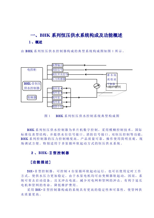
一、BHK系列恒压供水系统构成及功能概述1、概述由BHK系列恒压供水控制器构成的典型系统构成图如图1所示。
图1BHK系列恒压供水控制系统典型构成图BHK系列恒压供水控制器为单片机数字控制,采用模糊控制技术,国际标准仪表型结构。
并提供水位信号接口、消防信号接口、双恒压控制等功能,BHK系列控制器的压力控制精度高、产品质量可靠、操作使用简明直观,现场调试方便。
特别适用于多泵循环软起动方式的恒压供水系统。
2、BHK-Ⅱ型控制器[功能描述]BHK-Ⅱ型控制器,可控制4台泵循环软起动运行,也可以使用定时工作方式,使供水压力更加稳定。
由于水泵电机均可由变频器软起动,因而,系统可省去启动设备,且无冲击电流,减少对电网和管网的冲击,有利于延长电机和管网的寿命,降低维护费用。
采用BHK-Ⅱ型控制器构成的系统具有更高的稳定性和可靠性,使管网供水质量更高。
⑴. BHK控制器端子说明⑵BHK控制板端子图注1:消防输入端与地端接通时执行生活压力,断开时执行消防压力注2:水位输入端与地端接通时正常供水,断开时,水位指示灯亮,各泵相继停止(面板显示代码E 1)注3:变频器故障输入端与地端接通时为变频器故障状态。
(面板显示代码E 2)注4:各交流接触器接线端子的极限容量为3A/400V。
二、面板操作说明1、[运行及状态指示]运行指示:当控制器运行输入端子5与地3接通时,运行指示灯亮,控制器开始工作。
消防指示:当消防输入信号端子4与地端3断开时,消防指示灯亮,控制器执行消防压力。
水位指示:当水位输入信号端子7与地端3断开时,水位指示灯亮,各泵相继停止。
2、[系统设置/工作状态指示]首先根据系统的配置情况,设置各泵。
通过按面板上相应的系统设置按键,改变对应泵的预设定,对应按键的指示灯亮时,表示系统已配置该泵。
对应按键的指示灯闪烁时,表示该泵正在工作。
启动时按1#泵、2#泵、3#泵、4#泵的顺序启动,停止时按1#泵、2#泵、3#泵、4#泵的顺序停止。
SKD-3000B数控配置及作业能力20140922
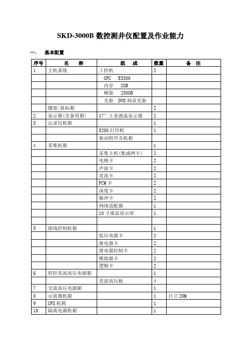
SKD-3000B数控测井仪配置及作业能力一.基本配置二.技术指标·信号通道:8道12位A/D通道(模拟通道);1道12位高速A/D通道;8道16位计数通道;PCM通道(3502、3506、3508、WTC)。
·深度系统:深度采样率:8、16、32、64、128、256、512点/米或10、20、40、80、160、320点/米;工作方式:马丁代克、井口马达,公英制切换;·软件处理:操作界面:基于WINDOWS2000的多任务测井操作系统;测井方式:上测、下测、上/下测、点测及时间驱动;出图及坐标显示:线性或对数坐标,对数坐标可由用户任意编辑;出图深度比例:1:20,1:50,1:100,1:200,1:500;出图格式:中文/英文两种方式;记录格式:仿716计算机用户带格式、LIS格式;测后处理:具有曲线的深度平移、拼接、深度校正、曲线合并、曲线抽取、重计算等测后处理功能;三.作业能力可配接83系列、3700系列、DDL-3,完成裸眼测井、生产测井、射孔取芯作业。
可配接以下下井仪完成裸眼井测井任务:1.聚能声波(22所SCB-5补偿声波仪、西仪厂SB91型聚能声波测井仪);2.双感应八侧向;3.自然GR4.双侧向(22所双侧向,3506编码、西仪厂JSC801,3502编码);5.微球(22所WQ-85、西仪厂WQJ114);6.补偿密度;7.补偿中子;8.常规电极系;9.四臂井径;10.微电极+井径组合仪;11.连续测斜仪(22所连斜,3506编码、华北连斜以及航天部33所连斜);12.兼容3700系列全部常规仪器,包括1229双侧向,3104微侧向,1309伽玛,2435中子,2227密度,1609声速。
13.井径+连斜井下仪的组合测井;14.连斜+井径+微电极组合测井;15.声波+感应+伽马组合测井;16.微球+双侧向组合测井;17.声波+感应+伽马+中子+密度+PCM3506组合测井;18.3506编码的井温流体张力三参数测井;可配接以下下井仪完成生产井测井任务:1.产液剖面测井:流量、含水、磁定位、压力、井温、自然GR、密度。
- 1、下载文档前请自行甄别文档内容的完整性,平台不提供额外的编辑、内容补充、找答案等附加服务。
- 2、"仅部分预览"的文档,不可在线预览部分如存在完整性等问题,可反馈申请退款(可完整预览的文档不适用该条件!)。
- 3、如文档侵犯您的权益,请联系客服反馈,我们会尽快为您处理(人工客服工作时间:9:00-18:30)。
微机变频恒压供水控制器使用手册(-3000-30, -40型)目录一、控制器的特点------------------------------------------------------1二、控制器的功能------------------------------------------------------1三、技术指标------------------------------------------------------------2四、安装和配线---------------------------------------------------------21、端子接线图---------------------------------------------------22、控制器端子说明---------------------------------------------33、与常用变频器的连接---------------------------------------34、常用接线原理图---------------------------------------------3五、参数及说明---------------------------------------------------------3六、面板及操作---------------------------------------------------------81、面板------------------------------------------------------------82、参数编辑操作------------------------------------------------9七、显示项目及故障说明---------------------------------------------9八、选型指南------------------------------------------------------------9附:四泵循环软启原理图一、特点本系列产品采用最新的微电脑控制技术,它和变频器、水泵组合即构成生活、消防或两者共用供水系统。
特点:功能强大:定时换泵,定时开关机,定量泵巡查,附属小泵等功能,使整套设备能满足不同用户要求。
配置灵活:循环方式2-4台泵+1台附属小泵;固定方式1台变频泵+1-8台定量泵。
使用方便:面板表卡式安装,安装使用方便。
防尘、防水工业面板,CE标准设计。
调试简单:简化键盘菜单式设定和调整工作状态,采用智能PID算法,PID参数自整定,高精度,高可靠性。
可靠性高:采用开关电源供电和SMD表面封状工艺使整机可靠性更高。
硬件WATCHDOG(看门狗)故障复位,另外每秒钟微机自动复位一次和输出状态硬件锁存电路,软件上引入容错概念和去干扰等算法。
内部带有屏蔽层隔离,在硬件上增强了抗干扰能力。
二、功能可在线编程和在线修改压力。
一至四泵工作可编程设定。
工作方式可设循环软起和直接启动。
泵全软起动,以先起先停为原则。
无加泵需要时可定时换泵工作。
可设定上限保护压力。
可设定(0-5V)或(4-20mA)输入。
可补偿传感器误差。
远传消防功能。
锅炉补水时,采用动静压方式。
设定压力和实时压力显示。
变频器频率显示和实时压力显示。
具有变频器故障、远传表故障或欠压超时和水位、报警指示。
具有实时时钟(带掉电保护)功能。
可编程每日8段高低压供水及开关机。
具有两种节能模式,休眠功能和带附属小泵功能。
可编程工作期限。
完善的密匙功能三、技术指标使用电源:AC 85V - 275V功耗:< 3W触点容量:5A / 250 AC 5A / 30V DC使用温度:0°C ~ 40°C储存温度:-100°C ~ 85°C相对湿度:20 ~ 90 RH开孔尺寸:宽152mm高mm76。
安装方法:插入式。
安装环境:无水滴、蒸汽、腐蚀和易燃气体、灰尘、金属微粒之场所。
四、安装和配线1、控制器端子接线图如下:端子说名5V / IN / COM模拟输入,连接电阻远传压力表。
接4-20mA信号时,在IN和COM间接250欧姆精密电阻。
I1低水位信号输入。
I1输入有效时,系统停止运行,显示Er01报警。
当I1输入无效时,系统恢复运行。
I2外部报警信号输入。
I2输入有效时,系统停止运行,显示Er02报警。
按编程键可取消报警。
I3I3有效时,4有效时,系统以参数Pr01为设定压力运行或者取消时钟控制(在时钟控制有效的情况下)。
G2I1 ,I2, I3的公共端D/A -- G模拟输出。
0—10V电压信号,接变频器频率控制端子。
FR / RM / CM变频器运行控制端, 集电极开路输出,CM为公共端,容量30mA。
FR与CM(常开点)接变频器运行控制端,RM与CM(常闭点)接变频器滑行停止端(当系统工作于循环启动方式时,否则不必)。
若变频器无滑行停止端子,应将变频器停止方式设为滑行停车方式。
B1—B4变频泵控制输出,容量5A, 接交流220V接触器。
D1—D4工频泵控制输出,容量5A, 接交流220V接触器。
D5 附属小泵控制接点,容量5A, 接交流220V接触器。
PE / N / L AC220V电源,PE为接地端。
3、与常用变频器的连接富士西门子三星台达三肯松下电器明电舍ABBD/A12311AVI VRF FIN FSV AI1G1149ACM ACM G COM AGND FR FWD5,61FWD FR I1FRUN DI1RM X8RST R/M I4CM CM97DCM DCM1G RYO DCOM1注:1、将变频器的频率控制和起停设为外部控制方式。
2、若变频器无滑行停止端子,应将变频器停止方式设为滑行停车方式(或叫自由停车方式)。
3、控制回路应用屏蔽线,且务必要与强电回路分开布线。
很多用户在配线时为追求美观都会把控制回路和变频器的380V输入输出线放到一个线槽或捆在一起,因为变频器是工作于SPWM方式,强电回路含有高次谐波具有有很强的干扰性,会通过控制回路对系统造成干扰,所4、请务必在接触器线圈两端并联R-C灭弧器。
接触器在吸合和断开的瞬间其线圈两端会产生很高的反电动势,造成控制器内继电器触点打火,严重干扰控制器的运行,短时间也许不会有问题,但系统还是常年不间断运行的,为保证系统常年运行的可靠性请务必在接触器线圈两端并联R-C灭弧器,又称阻容吸收器。
最好根据接触器的容量选折成品,自制可选68欧姆/2W电阻串耐压2000V CBB聚丙稀薄膜电容器(务必要选2000V以上优质电容,选择普通电容很容易激穿)。
4、常用接线原理图标准四台泵循环软启动方式原理图(以三垦变频器为例,见附页)。
五、参数及说明注:1.带阴影的参数只在上电倒计时状态下,按编程键进入编程状态才可修改。
2.密码的使用a. 在编程状态下,将Pr29-- Pr31设为非55的数值(55为出厂值,设为非55的数值可以避免误操作),切记记下此三个密码。
b. Pr32设置适当值,按确认键后既进入倒计时状态,Pr32不可再编辑。
3.密码的取消在上电倒计时状态下按编程键进入编程状态,将Pr29-- Pr31分别输入事先输入的密码,按确认键,然后从新上电既取消倒计时工作。
六、面板及操作1、 面板编程键在任何状态下按此键进入或退出编程状态。
增加键在编程状态下,增加参数号或数据。
在运行状态下,增大设定压力。
减小键在编程状态下,减小参数号或数据。
在运行状态下,减小设定压力。
确认键在编程状态下,用于存储改变的数据。
在运行状态下,改变显示内容,“Hz”灯熄灭时,显示“设定压力”,反之显示“频率”。
手动换泵在自动运行状态下,若只有一台泵运行,则进行换泵操作。
启动/停止启动或停止系统运行。
系统停止运行时,数码显示会闪烁。
#1 #2 #3 #4 分别指示相应泵的状态,闪烁表示变频运行,常亮表示工频运行。
FIRE SLEEP TIME PROG RUN 分别指示火灾、休眠状态、显示时间、编程状态、运行状态。
2、参数编辑操作操作按键显示1.任一状态下按编程键“ PROG ”灯亮Cd 00 2.按上升键或下降键到需修改的参数项,例如Cd12Cd 12 3.按确认键显示当前设定值01 4.例如将Cd12改为0,按下降键00 5.按确认键存储该值Cd 13 6.退出编程键编程状态,显示原状态如:设定压力和实际压力30 30七、显示项目及故障说明八、选型指南1.2泵一用一备型:BHK3000 – 1 0 / T2.2泵循环软起型:BHK3000 – 2 0 / T3.3泵循环软起型:BHK3000 – 3 0 / T显示项目说明D XX开机延时倒计数。
XX XX显示设定压力和实际压力。
频率指示灯亮时,显示频率(左侧两位)和实际压力Er 01低水位故障(I1输入有效)Er 02变频器故障/ 超压报警(I2输入有效)Er 03压力表故障。
Er 04到工作期限。
4.4泵循环软起型:BHK3000 – 4 0 / T/ T :表示带时钟控制功能此位为1,表示带附属小泵例如:BHK2002 – 31 / T为3泵循环软起带时钟、带附属小泵。