PM04-51.4_VL01_VL06_DS_ZOES_250_Rev_a_
rohm p02sct3040kr-evk-001 sic mosfet for to-247-4l
TO-247-4LHalf-Bridge Evaluation Board Operation ManualNotice <High Voltage Safety Precautions>◇ Read all safety precautions before usePlease note that this document covers only the SiC MOSFET for TO-247-4L evaluation board (P02SCT3040KR-EVK-001) and its functions. For additional information, please refer to the product specification.To ensure safe operation, please carefully read all precautions before handling the evaluation boardDepending on the configuration of the board and voltages used,Potentially lethal voltages may be generated.Therefore, please make sure to read and observe all safety precautions described inthe red box below.This evaluation board is intended for use only in research and development facilities and should by handled only by qualified personnel familiar with all safety and operating procedures.We recommend carrying out operation in a safe environment that includes the use of high voltage signage at all entrances, safety interlocks, and protective glasses.User’s GuideSiC MOSFET 评估板TO-247-4L 半桥评估板 使用说明书在SiC MOSFET 等功率元器件的评估中,一般会涉及到高电压和大电流,因此要求恰当地构建其评估环境。
奥美晨曦系列微波传感器说明书

OS100 SERIES Mini-Infrared Transmitter e-mail:**************For latest product manuals: Shop online at User’s G ui d e***********************Servicing North America:U.S.A. Omega Engineering, Inc.Headquarters: Toll-Free: 1-800-826-6342 (USA & Canada only)Customer Service: 1-800-622-2378 (USA & Canada only)Engineering Service: 1-800-872-9436 (USA & Canada only)Tel: (203) 359-1660 Fax: (203) 359-7700e-mail:**************For Other Locations Visit /worldwideThe information contained in this document is believed to be correct, but OMEGA accepts no liability for any errors it contains, and reserves the right to alter specifications without notice.Table of ContentsSection ...................................................................PageSafety Warnings and IEC Symbols (iii)Caution and Safety Information (iii)Section 1 Introduction ....................................................................1-1Section 2Installation ......................................................................1-12.1 Unpacking and Inspection ......................................1-12.2 Electrical Connection ..............................................2-1Section 3Operation ........................................................................3-13.1 Main Board ................................................................3-13.2 Ambient Temperature ..............................................3-23.3 Atmospheric Quality ................................................3-33.4 Measuring Temperature ..........................................3-33.5 Alarm Setting ............................................................3-43.6 Adding Extension Cable...........................................3-4Section 4 Laser Sight Accessory ...................................................4-14.1 Warning and Cautions .............................................4-14.2 Operating the Laser Sight Accessory .....................4-1Section 5 Specifications .................................................................5-15.1 General .......................................................................5-15.2 Laser Sight Accessory (OS100-LS) ..........................5-2Section 6Emissivity Table .............................................................6-1iTable of FiguresFigure Description Page2-1Power Supply & Analog Output Connections ..........2-12-2 Alarm Output Connection ............................................2-13-1 Main PC Board ...............................................................3-23-2 Sensor..............................................................3-2Housing3-3 Optical Field of View .....................................................3-43-4Setting the Temperature Engineering Unit..................3-43-5Mounting Bracket OS100-MB .......................................3-53-6Water Cooling Jacket, OS100-WC ................................3-53-7Typical Water Cool Jacket Assembly ...........................3-53-8Air Purge Collar, OS100-AP..........................................3-63-9DIN Rail Mounting Adapter, OS100-DR ....................3-63-10NEMA-4 Aluminum Enclosure ....................................3-64-1Laser Sighting Accessory, OS100-LS ............................4-24-2Laser Warning Label ......................................................4-2iiSafety Warnings and IEC SymbolsThis device is marked with international safety and hazard symbols in accordance with IEC 1010. It is important to read and follow all precautions and instructions in this manual before operating or commissioning this device as it contains important information relating to safety and EMC. Failure to follow all safety precautions may result in injury and or damage to your calibrator. IEC symbols DescriptionCaution and Safety Information• If the equipment is used in a manner not specified in this manual, the protection provided by the equipment may be impaired.• The installation category is one (1).• There are no user replaceable fuses in this product• The output terminals of this product are for use with equipment (digital meters, chart recorders, etc,) which have no accessible five parts. Such equipment should comply with all the applicable safety requirements.• Do not operate the equipment in flammable or explosive environments.• All connections to the thermometer should be made via a shielded cable, 24 AWG stranded wire with the following ratings: 300V , 105°C (221°F), PVC insulation.• Power must be disconnected before making any electrical connections.• The power supply used to power the thermometer should be VDE or UL approved with the following ratings: 12 to 24vdc @150mA with overload protection of 500mA.iiiCaution, refer to accompanying documentsDirect Current Laser SymbolFrame or ChassisNOTES: ivSection 1 - IntroductionThe low cost OS101 mini-infrared transmitter provides non-contacttemperature measurement for industrial applications. The unit measures atemperature range of -18 to 538°C (0-1000°F) and provides a linear analogoutput of either 4-20 mA, 0-5 VDC, K type TC, 1 mV/°C, or 1 mV/°F.The new OS102 mini-infrared transmitter has all the functions of OS101plus a built-in LED display that shows the measured temperature indegrees F or degrees C which is switchable in the field.The miniature sensor head design 2.5 cm dia. x 6.3 cm Length (1" x 2.5") isideal for measuring temperature in confined, and hard to reach places.The aluminum sensor head as well as the rugged electronic housing (Diecast Aluminum) are NEMA-4 rated.The sensor head is connected to the electronic housing via a 1.82 m (6 feet)shielded cable as standard. The unit provides field adjustable alarmoutput.Section 2 - Installation2.1UnpackingRemove the packing list and verify that you have received all yourequipment. If you have any questions about the shipment, please callCustomer Service at:1-800-622-2378 or 203-359-1660. We can also be reached on the internet:e-mail:**************When you receive the shipment, inspect the container and equipment forany signs of damage. Note any evidence of rough handling in transit.inspection. After examination and removing contents, save packing material and carton in theevent reshipment is necessary.The following items are supplied in the box:• The infrared transmitter including the sensor head and the 1.82 m(6 feet) shielded cable• User's Manual• Mounting Nut1-1The following describes the ordering information:OS102 or OS101 - MA- *,**, where The following optional accessories are available:Here are the Features of OS101 and OS102 infrared transmitters:2.2Electrical Connection Sensor Head Cable - The Sensor head is pre-wired to a 1.8 m (6 feet)shielded cable. Plug & lock-in the male connector to the mating female connector on the aluminum housing.Power & Output Connection - Open the cover of the main aluminum housing. Slide the cable through the strain relief and connect the wires to the terminal block on the board as shown in Fig. 2-1. For Alarm output connection, refer to Fig. 2-2.2-1MA - 4/20 mA output V1 - 0 to 5 VDC output K - Thermocouple output, K type MV - Millivolt output C - 1 mV/°C output F - 1 mV/°F output HT- High temperature sensor head3-1Figure 2-2. Alarm Output Connection Section 3 - Operation3-1Main BoardThe Main Board is shown in Fig. 3-1. Here are the important components on the board:(1) - Terminal Block for Power & Output connections(2) - Single Turn Potentiometer to adjust Emissivity in tenths (0.x_)(3) - Single Turn Potentiometer to adjust Emissivity in hundreds (0._x)(4) -Slide switch to select between real time (Normal Operation) and alarm set point(5) - Alarm set point adjust, P4(6) - Sensor Head connection(7) - Input Zero adjust, P3(8) - Input Span adjust, P2(9) - Output Zero adjust, P5(10) - Output Span adjust, P6Figure 3-1. Main PC Board3.2Ambient TemperatureThe Sensing head can operate in an ambient temperature of 0 to 70°C (32to 158°F). The Sensing head in the high temperature model (-HT) can operate in an ambient temperature of 0 to 85°C (32 to 185°F) without any cooling required. The Sensing head can operate up to 200°C (392°F) using the water cool jacket accessory OS100-WC (See Fig. 3-6).There is a warm up period of 3 minutes after power up. After the warm up period, temperature measurement can be made.When the ambient temperature around the sensor head changes abruptly,the sensor head goes through thermal shock. It takes a certain amount of time for the sensor head to stabilize to the new ambient temperature. For example, it takes about 30 minutes for the sensor head to stabilize going from 25°C to 50°C (77 to 122°F) ambient temperature.The sensor head dimensions are shown in Fig. 3-2.Figure 3-2. Sensor Housing3-23-33.3Atmospheric QualityEnvironments with smoke, dust, and fumes dirty up the optical lens, and cause erroneous temperature readings. To keep the surface of the optical lens clean, the air purge collar accessory is recommended, OS100-AP , See Fig. 3-7.3.4Measuring TemperatureBefore starting to measure temperature, make sure that the following check list is met:ߜ The power and analog output connections are made (Fig. 2-1).ߜThe sensor head is connected to the main unit.ߜThe slide switch (SW1) on the main board is set to real time (Fig. 3-1).ߜThe target is larger than the optical field of view of the sensor head (Fig. 3-3).ߜThe emissivity adjustment on the main board is set properly (Fig. 3-1).ߜThe output load is within the product specification.On OS102 transmitters, follow these additional steps:ߜ The temperature display is set to °F or °C (Fig. 3-4)ߜ For 4-20mA output models, make sure an output load is added, ie. 250ohms.Figure 3-3. Optical Field Of ViewFigure 3-4. Setting the Temperature Engineering Unit3.5Alarm SettingThe unit provides 0-100% alarm set point adjustment. Here is an exampleof an alarm setting.• An OS101-MA(4/20 mA output), the alarm is to be set at 400°Ftemperature.• Connect the alarm output as shown in Fig. 2-2.• Set the slide switch (SW1) on the main board to the Alarm position.• Measure the analog output, and set the Potentiometer P4 until theoutput reads 10.4 mA which is 40% (400°F) of the temperature range.40 x (20-4)[10.4mA=+ 4]100• Set the slide switch (SW1) back to the Real Time position.• If the temperature reading is below the alarm set point, the alarmoutput stays high, otherwise it goes low.On the OS102, you can set the alarm set point directly based on thetemperature display.3.6Adding Extension CableYou can add extension cable between the Sensor Head and the mainelectronic housing up to 15.2 m (50 feet). After adding the extension cable,the Zero input potentiometer, P3 may be re-adjusted. (See Fig. 3-1, forproper analog output reading)The following figures show the mounting bracket (OS100-MB), Watercooling jacket (OS100-WC), Air purge collar (OS100-AP), DIN RailMounting adapter (OS-100-DR), and the main aluminum enclosure. TheDIN Rail Mounting adapter (OS100-DR) is mounted to the bottom of themain aluminum enclosure using two 4-40 screws.A typical water cool jacket assembly is shown in Fig. 3-7, on the following page.1. Mounting Nut2. Mounting Bracket3. Water Cool Jacket4. Sensor Head3-4Figure 3-5. Mounting Bracket OS100-MBFigure 3-6. Water Cooling Jacket, OS100-WCFigure 3-7. Typical Water Cool Jacket Assembly3-5Figure 3-8. Air Purge Collar, OS100-APFigure 3-9. DIN Rail Mounting Adapter, OS-100-DRFigure 3-10. NEMA-4 Aluminum Enclosure3-6Section 4 - Laser Sight Accessory4.1Warning and Cautionsbelow:•Use of controls or adjustments or performance of procedures other than those specified here may result in hazardous radiation exposure.• Do not look at the laser beam coming out of the lens or view directly with optical instruments - eye damage can result.• Use extreme caution when operation the laser sight accessory • Never point the laser accessory at a person • Keep out of the reach of all children4.2Operating the Laser Sight AccessoryThe laser sight accessory screws onto the front of the sensor head. This accessory is only used for alignment of the sensor head to the target area.After the alignment process, the accessory has to be removed from the front of the sensor head before temperature measurement.The laser sight accessory is powered from a small compact battery pack (included with the accessory). Connect the battery pack to the accessory using the cable provided. Aim at the target, and turn on the battery power using the slide switch on the battery pack. Adjust the sensor head position so that the laser beam points to the center of the target area. Turn off the battery pack, and remove the laser sighting accessory from the sensor head. See Fig. 4-1 for reference.4-14-2Figure 4-2. Laser Warning LabelSection 5 - Specifications5.1 - GeneralTemperature Range-18 to 538°C (0 to 1000°F)Accuracy @ 22°C (72°F)±2% of Rdg. or 2.2°C (4°F) whichever is ambient temperature & greateremissivity of 0.95 or greaterOptical Field of View6:1 (Distance/Spot Size)Repeatability±1% of Rdg.Spectral Response 5 to 14 micronsResponse Time150 msec (0 to 63% of final value)Emissivity Range0.1 to 0.99, adjustableOperating Ambient TemperatureMain Transmitter0 to 50°C (32 to 122°F)Sensor Head0 to 70°C (32 to 158°F)Sensor Head (-HT Model)0 to 85°C (32 to 185°F)Sensor Head with OS100-WC(Water Cooling Jacket)0 to 200°C (32 to 392°F)Operating Relative Humidity Less than 95% RH, non-condensingWater Flow Rate for OS100-WC0.25 GPM, room temperatureThermal Shock About 30 minutes for 25°Cabrupt ambient temperature change Warm Up Period 3 minutesAir Flow Rate for OS100-AP 1 CFM (0.5 Liters/sec.)Power12 to 24 VDC @ 100 mAAnalog OutputsMV-F 1 mV/°FMV-C 1 mV/°CK K Type TC - OS101 onlyMA 4 to 20 mAV10 to 5 VDCOutput Load requirementsMin. Load (0 to 5VDC) 1 K-OhmsMax. Load (4 to 20 mA)(Supply Power - 4 )/20 mATransmitter Housing NEMA-4 & IP65, Die Cast AluminumSensor Head Housing NEMA-4 , AluminumAlarm Output Open Drain, 100 mAAlarm Set Point0 to 100% , Adjustable via P4Alarm Deadband14°C (25°F)5-15-25.1 - General Con’t.DimensionsSensor Head25.4 OD. x 63.5 mm L(1" OD. x 2.5" L)Main Housing, OS10165.5 W x 30.5 H x 115.3 mm L(2.58" W x 1.2" H x 4.54" L)Main Housing, OS10265.5 W x 55.9 H x 115.3 mm L(2.58" W x 2.2" H x 4.54" L)Weight 272 g (0.6 lb)5.2Laser Sight Accessory (OS100-LS)Wavelength (Color)630 - 670 nm (Red)Operating Distance (Laser Dot)Up to 9.1 m (30 ft.)Max. Output Optical Power Less than 1 mW at 22°F ambienttemperature.European Classification Class 2, EN60825-1/11.2001Maximum Operating current45 mA at 3 VDCFDA Classification Complies with 21 CFR 1040.10,Class II Laser ProductBeam Diameter 5 mmBeam Divergence< 2 mradOperating Temperature0 to 50°C (32 to 122°F)Operating Relative Humidity Less than 95% RH, non-condensingPower Switch ON / OFF , Slide switch on the BatteryPackPower Indicator Red LEDPower Battery Pack, 3 VDC (Consists of two 1.5VDC AA size Lithium Batteries) Laser Warning Label Located on the head sight circumferenceIdentification Label Located on the head sight circumferenceDimensions38 DIA x 50.8 mm L(1.5" DIA x 2" L)Section 6 - Emissivity Table6-1Material Emissivity (ε)Aluminum – pure highly polished plate . . . . . . . . . . . . . . . . . . . . . . . . 0.04 to 0.06Aluminum – heavily oxidized . . . . . . . . . . . . . . . . . . . . . . . . . . . . . . . 0.20 to 0.31Aluminum – commercial sheet . . . . . . . . . . . . . . . . . . . . . . . . . . . . . . . . . . . . 0.09Brass – dull plate. . . . . . . . . . . . . . . . . . . . . . . . . . . . . . . . . . . . . . . . . . . . . . 0.22Brass – highly polished, 73.2% Cu, 26.7% Zn. . . . . . . . . . . . . . . . . . . . . . . . . 0.03Chromium – polished. . . . . . . . . . . . . . . . . . . . . . . . . . . . . . . . . . . . . 0.08 to 0.36Copper – polished. . . . . . . . . . . . . . . . . . . . . . . . . . . . . . . . . . . . . . . . . . . . . 0.05Copper – heated at 600°C (1112°F). . . . . . . . . . . . . . . . . . . . . . . . . . . . . . . 0.57Gold – pure, highly polished or liquid. . . . . . . . . . . . . . . . . . . . . . . . . 0.02 to 0.04Iron and steel (excluding stainless)– polished iron . . . . . . . . . . . . . . . . 0.14 to 0.38Iron and steel (excluding stainless)– polished cast iron. . . . . . . . . . . . . . . . . . . 0.21Iron and steel (excluding stainless)– polished wrought iron . . . . . . . . . . . . . . . 0.28Iron and steel (excluding stainless)– oxidized dull wrought iron . . . . . . . . . . . . 0.94Iron and steel (excluding stainless)– rusted iron plate . . . . . . . . . . . . . . . . . . . 0.69Iron and steel (excluding stainless)– polished steel. . . . . . . . . . . . . . . . . . . . . . 0.07Iron and steel (excluding stainless)– polished steel oxidized at600°C (1112°F). . . . . . . . . . . . . . . . . . . . 0.79Iron and steel (excluding stainless)– rolled sheet steel . . . . . . . . . . . . . . . . . . . 0.66Iron and steel (excluding stainless)– rough steel plate . . . . . . . . . . . . . 0.94 to 0.97Lead – gray and oxidized . . . . . . . . . . . . . . . . . . . . . . . . . . . . . . . . . . . . . . . 0.28Mercury . . . . . . . . . . . . . . . . . . . . . . . . . . . . . . . . . . . . . . . . . . . . . 0.09 to 0.12Molybdenum filament . . . . . . . . . . . . . . . . . . . . . . . . . . . . . . . . . . . . 0.10 to 0.20Nickel – polished . . . . . . . . . . . . . . . . . . . . . . . . . . . . . . . . . . . . . . . . . . . . . 0.07Nickel – oxidized at 649 to 1254°C (1200°F to 2290°F). . . . . . . . . . . 0.59 to 0.86Platinum – pure polished plate . . . . . . . . . . . . . . . . . . . . . . . . . . . . . . 0.05 to 0.10Platinum – wire . . . . . . . . . . . . . . . . . . . . . . . . . . . . . . . . . . . . . . . . 0.07 to 0.18Silver – pure and polished . . . . . . . . . . . . . . . . . . . . . . . . . . . . . . . . . 0.02 to 0.03Stainless steel – polished . . . . . . . . . . . . . . . . . . . . . . . . . . . . . . . . . . . . . . . . 0.07Stainless steel – Type 301 at 232 to 942°C (450°F to 1725°F). . . . . . . 0.54 to 0.63Tin – bright . . . . . . . . . . . . . . . . . . . . . . . . . . . . . . . . . . . . . . . . . . . . . . . . . 0.06Tungsten – filament . . . . . . . . . . . . . . . . . . . . . . . . . . . . . . . . . . . . . . . . . . . . 0.39Zinc – polished commercial pure . . . . . . . . . . . . . . . . . . . . . . . . . . . . . . . . . . 0.05Zinc – galvanized sheet. . . . . . . . . . . . . . . . . . . . . . . . . . . . . . . . . . . . . . . . . 0.23M E T A L S6-2Material Emissivity (ε) Asbestos Board . . . . . . . . . . . . . . . . . . . . . . . . . . . . . . . . . . . . . . . . . . . . . . .0.96 Asphalt, tar, pitch . . . . . . . . . . . . . . . . . . . . . . . . . . . . . . . . . . . . . . .0.95 to 1.00 Brick– red and rough . . . . . . . . . . . . . . . . . . . . . . . . . . . . . . . . . . . . . . . . . .0.93 Brick– fireclay . . . . . . . . . . . . . . . . . . . . . . . . . . . . . . . . . . . . . . . . . . . . . . .0.75 Carbon– filament . . . . . . . . . . . . . . . . . . . . . . . . . . . . . . . . . . . . . . . . . . . . .0.53 Carbon– lampblack - rough deposit . . . . . . . . . . . . . . . . . . . . . . . . . .0.78 to 0.84 Glass- Pyrex, lead, soda . . . . . . . . . . . . . . . . . . . . . . . . . . . . . . . . . .0.85 to 0.95 Marble– polished light gray . . . . . . . . . . . . . . . . . . . . . . . . . . . . . . . . . . . . .0.93 Paints, lacquers, and varnishes– Black matte shellac . . . . . . . . . . . . . . . . . . . .0.91 Paints, lacquers, and varnishes– aluminum paints . . . . . . . . . . . . . . . .0.27 to 0.67 Paints, lacquers, and varnishes– flat black lacquer . . . . . . . . . . . . . . .0.96 to 0.98 Paints, lacquers, and varnishes– white enamel varnish . . . . . . . . . . . . . . . . . .0.91 Porcelain– glazed . . . . . . . . . . . . . . . . . . . . . . . . . . . . . . . . . . . . . . . . . . . . .0.92 Quartz– opaque . . . . . . . . . . . . . . . . . . . . . . . . . . . . . . . . . . . . . . . .0.68 to 0.92 Roofing Paper . . . . . . . . . . . . . . . . . . . . . . . . . . . . . . . . . . . . . . . . . . . . . . .0.91 Tape– Masking . . . . . . . . . . . . . . . . . . . . . . . . . . . . . . . . . . . . . . . . . . . . . .0.95 Water . . . . . . . . . . . . . . . . . . . . . . . . . . . . . . . . . . . . . . . . . . . . . . . .0.95 to 0.96 Wood– planed oak . . . . . . . . . . . . . . . . . . . . . . . . . . . . . . . . . . . . . . . . . . . .0.90 NONMETALSNOTES:6-3NOTES: 6-4OMEGA’s policy is to make running changes, not model changes, whenever an improvement is possible. T his affords our customers the latest in technology and engineering.OMEGA is a trademark of OMEGA ENGINEERING, INC.© Copyright 2017 OMEGA ENGINEERING, INC. All rights reserved. T his document may not be copied, photocopied, reproduced, translated, or reduced to any electronic medium or machine-readable form, in whole or in part, without the prior written consent of OMEGA ENGINEERING, INC.FOR WARRANTY RETURNS, please have the following information available BEFORE contacting OMEGA:1. P urchase Order number under which the product was PURCHASED,2. M odel and serial number of the product under warranty, and3. Repair instructions and/or specific problems relative to the product.FOR NON-WARRANTY REPAIRS, consult OMEGA for current repair charges. Have the following information available BEFORE contacting OMEGA:1. Purchase Order number to cover the COST of the repair,2. Model and serial number of the product, and 3. Repair instructions and/or specific problems relative to the product.RETURN REQUESTS/INQUIRIESDirect all warranty and repair requests/inquiries to the OMEGA Customer Service Department. BEFORE RET URNING ANY PRODUCT (S) T O OMEGA, PURCHASER MUST OBT AIN AN AUT HORIZED RET URN (AR) NUMBER FROM OMEGA’S CUST OMER SERVICE DEPART MENT (IN ORDER T O AVOID PROCESSING DELAYS). The assigned AR number should then be marked on the outside of the return package and on any correspondence.T he purchaser is responsible for shipping charges, freight, insurance and proper packaging to preventbreakage in transit.WARRANTY/DISCLAIMEROMEGA ENGINEERING, INC. warrants this unit to be free of defects in materials and workmanship for a period of 25 months from date of purchase. OMEGA’s WARRANTY adds an additional one (1) month grace period to the normal two (2) year product warranty to cover handling and shipping time. This ensures that OMEGA’s customers receive maximum coverage on each product.If the unit malfunctions, it must be returned to the factory for evaluation. OMEGA’s Customer Service Department will issue an Authorized Return (AR) number immediately upon phone or written request. Upon examination by OMEGA, if the unit is found to be defective, it will be repaired or replaced at no charge. OMEGA’s WARRANT Y does not apply to defects resulting from any action of the purchaser, including but not limited to mishandling, improper interfacing, operation outside of design limits, improper repair, or unauthorized modification. T his WARRANT Y is VOID if the unit shows evidence of having been tampered with or shows evidence of having been damaged as a result of excessive corrosion; or current, heat, moisture or vibration; improper specification; misapplication; misuse or other operating conditions outside of OMEGA’s control. Components in which wear is not warranted, include but are not limited to contact points, fuses, and triacs.OMEGA is pleased to offer suggestions on the use of its various products. However, OMEGA neither assumes responsibility for any omissions or errors nor assumes liability for any damages that result from the use of its products in accordance with information provided by OMEGA, either verbal or written. OMEGA warrants only that the parts manufactured by the company will be as specified and free of defects. OMEGA MAKES NO OTHER WARRANTIES OR REPRESENTATIONS OF ANY KIND WHATSOEVER, EXPRESSED OR IMPLIED, EXCEPT THAT OF TITLE, AND ALL IMPLIED W ARRANTIES INCLUDING ANY W ARRANTY OF MERCHANTABILITY AND FITNESS FOR A PARTICULAR PURPOSE ARE HEREBY DISCLAIMED. LIMITATION OF LIABILITY: The remedies of purchaser set forth herein are exclusive, and the total liability of OMEGA with respect to this order, whether based on contract, warranty, negligence, indemnification, strict liability or otherwise, shall not exceed the purchase price of the component upon which liability is based. In no event shall OMEGA be liable for consequential, incidental or special damages.CONDITIONS: Equipment sold by OMEGA is not intended to be used, nor shall it be used: (1) as a “Basic Component” under 10 CFR 21 (NRC), used in or with any nuclear installation or activity; or (2) in medical applications or used on humans. Should any Product(s) be used in or with any nuclear installation or activity, medical application, used on humans, or misused in any way, OMEGA assumes no responsibility as set forth in our basic WARRANT Y /DISCLAIMER language, and, additionally, purchaser will indemnify OMEGA and hold OMEGA harmless from any liability or damage whatsoever arising out of the use of theProduct(s) in such a manner.Where Do I Find Everything I Need forProcess Measurement and Control?OMEGA…Of Course!Shop online at TEMPERATUREM U Thermocouple, RTD & Thermistor Probes, Connectors,Panels & AssembliesM U Wire: Thermocouple, RTD & ThermistorM U Calibrators & Ice Point ReferencesM U Recorders, Controllers & Process MonitorsM U Infrared PyrometersPRESSURE, STRAIN AND FORCEM U Transducers & Strain GagesM U Load Cells & Pressure GagesM U Displacement TransducersM U Instrumentation & AccessoriesFLOW/LEVELM U Rotameters, Gas Mass Flowmeters & Flow ComputersM U Air Velocity IndicatorsM U Turbine/Paddlewheel SystemsM U Totalizers & Batch ControllerspH/CONDUCTIVITYM U pH Electrodes, Testers & AccessoriesM U Benchtop/Laboratory MetersM U Controllers, Calibrators, Simulators & PumpsM U Industrial pH & Conductivity EquipmentDATA ACQUISITIONM U Communications-Based Acquisition SystemsM U Data Logging SystemsM U Wireless Sensors, Transmitters, & ReceiversM U Signal ConditionersM U Data Acquisition SoftwareHEATERSM U Heating CableM U Cartridge & Strip HeatersM U Immersion & Band HeatersM U Flexible HeatersM U Laboratory HeatersENVIRONMENTALMONITORING AND CONTROLM U Metering & Control InstrumentationM U RefractometersM U Pumps & TubingM U Air, Soil & Water MonitorsM U Industrial Water & Wastewater TreatmentM U pH, Conductivity & Dissolved Oxygen InstrumentsM3572/1217。
ATE Corporation AS-05 Antenna Set 30 MHz to 18 GHz

Main Features•30 MHz to 18 GHz frequency range •Excellent Antenna Factor•Tripod adapter for easy vertical-horizontal polarization change •Individual calibration•Robust, rustproof aluminium construction •LightweightAS-05 is a compact size broadband Antenna System composed of a BC-01 Biconical Dipole, LP-04 Log Periodic Dipole Array and DR-01 Double Ridged horn Antenna designed for radiated emissions and immunity testing. It can be used in conjunction with any receiver or spectrum analyzer.Its ideal companion is the EMI Receiver Unit 9060 and 9180 that can be easily mounted on the antenna mast (*).(*)The direct connection between antenna and PMM Receiver Unit eliminates additional sources of uncertainties due to coaxial cable attenuation and scattering. For further information please consult our brochure “Fully CISPR-Compliant Digital EMC/EMI receivers 10 Hz to 18 GHz”.Antenna Set 30 MHz to 18 GHzProvided by: (800)404-ATECAdvanced Test Equipment Rentals®Ordering Information:AS-05 antenna set 30 MHz to 18 GHz with individual calibration reports.AS-05/TC antenna set 30 MHz to 18 GHz with typical calibration reports.Includes: BC-01 biconical antenna; LP-04 Log-periodic antenna; DR-01Double-rideged antenna; TR-01 wooden tripod; RF cable, 6 GHz, N(m)-N(m), 5 m; Soft carrying case; Rigid carrying case (for DR-01), Operating manual; Calibration reports*.* Individual calibration reports are provided with AS-05.AS-05/TC does not include individual calibration but typical antenna factor.Optional accessories:Additional TR-01 Wooden tripod extensible 60 - 180 cm with antenna mounting adapter for fast horizontal to vertical polaritazion changing. Additional RF cable, 3 GHz, N(m)-N(m), 5 m.Sales Office:Via Leonardo da Vinci, 21/2320090 Segrate (Milano) - ITALY Phone: +39 02 2699871Fax: +39 02 26998700Headquarter:Via Benessea, 29/B17035 Cisano sul Neva (SV) - ITALY Phone: +39 0182 58641Fax: +39 0182 586400E-Mail:**************************Internet: www.narda-sts.itRelated ProductsReceiversAntennasCalibrations service• 7010/00: EMI receiver 150 kHz to 1 GHz • 7010/01: EMI receiver 9 kHz to 1 GHz • 7010/03: EMI receiver 9 kHz to 3 GHz • 9010: EMI receiver 10 Hz to 30 MHz • 9010F: EMI receiver 10 Hz to 30 MHz• 9010/03P: EMI receiver 10 Hz to 300 MHz • 9010/30P: EMI receiver 10 Hz to 3 GHz • 9010/60P: EMI receiver 10 Hz to 6 GHz • 9030: EMI Receiver 30 MHz to 3 GHz • 9060: EMI Receiver 30 MHz to 6 GHz •FR-4003: Field Receiver 9 kHz to 30 MHz• LP-02: Log Periodic Antenna 200 MHz to 3 GHz • LP-03: Log Periodic Antenna 800 MHz to 6 GHz • TR-01: Antenna Tripod• VDH-01: Van der Hoofden test-head 20 kHz to 10 MHz • Antenna Set AS-02 (BC01+LP02+TR01)• Antenna Set AS-03 (BC01+LP02+LP03+TR01) • Antenna Set AS-04 (BC01+LP04+TR01)• RA01: Rod Antenna 9 kHz to 30 MHz• RA01-HV: Rod Antenna 150 kHz to 30 MHz •RA01-MIL: Rod Antenna 9 kHz to 30 MHz• Ansi 63,5 Antenna Factor • SAE ARP 958-D• Free-Space Antenna FactorSPECIFICATIONSFrequency range GainAntenna factor Max input power Connector Dimensions (L x H x W)Weight Colour Impedance ConstructionBC-0130 to 200 MHz -15 +2 dBi typical 8 to 14 dB/m typical 100 W N-female 65 x 65 x 137 cm1,8 kg RAL 703550 Ω nominal AluminiumA S 05-F E N -60801 - S p e c i fi c a t i o n s s u b j e c t t o c h a n g e s w i t h o u t p r i o r n o t i c eAS-05Antenna set 30 MHz to 18 GHzLP-04200 MHz to 6 GHz 6 dBi typical 12 to 40 dB/m typical100 W N-female 78 x 10 x 75 cm 1,1 kg RAL 703550 Ω nominal AluminiumDR-016 to 18 GHz 9 to 16 dBi typical 36 to 41 dB/m typical 150 W N-female 55 x 44 x 177 mm 0,25 kg RAL 703550 Ω nominal AluminiumBC-01 - Antenna Factor 106141822A F (d B /m )3090150210MHz MHz MHz MHz LP-04 - Antenna Factor 155253545A F (d B /m )1356GHzGHz GHz GHz DR-01 - Antenna Factor3634384042A F (d B /m )6101418GHzGHz GHz GHz。
红狮自动化系列PM-50图形面板表仪说明书

PM-50Red Lion Automation SeriesAnalog Input Graphical Panel MetersPM-50 IS A PLATFORM OF METERS DESIGNED TO INCREASE OPERATOR PRODUCTIVITY AND EXPOSE CRITICAL PLANT FLOOR DATA FOR USE IN PROJECT SCHEDULING AND PROCESS IMPROVEMENTS. LOCAL OPERATORS CAN EASILY RELATE TO THE MORE INTUITIVE GRAPHICAL DISPLAY. SECONDARY DISPLAYS PROVIDE EVEN MORE DATA. THE METERS FEATURE ON-BOARD Wi-Fi, RS-485/MODBUS, AND OPTIONAL ETHERNET OR RS-232.C USU LIND.CONT. EQ.E317425GRAPHICAL DISPLAY\Full color touchscreen\Intuitive screens\Multiple displays SIMPLE PROGRAMMING \Start-up Wizard\Programming App\Web server ALARM NOTIFICATION \Display color change\Push messaging\Focuses attention DATA ACCESS\Wi-Fi\Modbus/RS485\Ethernet & RS232MODULAR CONSTRUCTION \Plug-in play modules\Upgradeable firmware\Outputs, power & comms EASY FIELD REPLACEMENT \Use existing wiring\4.3" - 1/8 DIN products\3.5" - 1/16 DIN products SMART DEVICE CAPABILITIES \Functionality\Programming\Connectivity\Meter SpecificationsDISPLAYUPDATE RATESA/D conversion rate: programmable 5 to 200 readings/sec. INPUT CAPABILITIESCurrent Input: ± 200 μA DC, ± 2 mA DC, ± 20 mA DC, ± 200 mA DC, ± 2 A DCVoltage Input: ± 200 mV DC, ± 2.0 V DC, ± 20 V DC, ± 60 V DC Thermocouple Input: T, E, J, K, R, S, B, N, C (W5/W26)RTD Input: 100 Ω Pt alpha = .00385, 100 Ω Pt alpha = .00392, 120 Ω Nickel alpha = .00672, 10 Ω Copper alpha = .00427 Resistance Input: 100 Ω, 1000 Ω, 10 KΩEXCITATION POWERTransmitter Power: +24 VDC, ± 5% @ 50 mA max.Reference Voltage: + 2 VDC, ± 2%Reference Current: 1.05 mADC, ± 2%USER INPUTSTwo programmable user inputsTOTALIZERTime Base: second, minute, hour, or dayBatch: Can accumulate (gate) input display from a user input Time Accuracy: 0.01% typicalDecimal Point: 0 to 0.0000Scale Factor: 0.001 to 65.000Low Signal Cut-out: -199,999 to 999,999T otal: Up to 9 digitsCUSTOM LINEARIZATIONData Point Pairs: Selectable from 2 to 40Display Range: -199,999 to 999,999Decimal Point: 0 to 0.0000MEMORYNonvolatile memory retains all programmable parameters and display values.Memory Card: microSD slot accepts up to 32 GB capacity cards in FAT16/FAT32 format.RS485 SERIAL PORTUses Modbus protocol (RTU and ASCII)Baud Rate: Up to 115,200Data Format: 7/8 bit; odd, even, or no parity; 1 or 2 stop bits Isolation: 500 Vrms to sensor, user power and digital inputs. Not isolated to solid state outputs\Ordering GuideMAIN UNITPM500A0400800F00 4.3" Analog Input Graphical Panel Meter PM500A0301600F00 3.5" Analog Input Graphical Panel Meter ACCESSORIESPMM000CM23200000RS232 Serial Communications ModulePMM000CMENT00000Ethernet Communications ModulePMM000I0AN000000Analog Output ModulePMM000I0RL200000Dual Setpoint Relay Output ModulePMM000I0RL400000Quad Setpoint Relay Output ModulePMM000PWACP00000AC to DC Power ModulePMA000CP00800000Replacement Rear Cover/Bus Board with Spacer Module(4.3" model only)PMA000MK00800000Conversion Panel 92 mm x 75 mm to 1/8 DINPMA000MK01600000Conversion Panel 68 mm x 68 mm to 1/16 DINPMA000MKLP00000Replacement Module Lock PinsPMA000SP00800000 4.3" Protective Screen OverlayPMA000SP01600000 3.5" Protective Screen OverlayWi-Fi CAPABILITIES:Wi-Fi: Power output up to 20.5 dBmconfigured country/region code.Wi-Fi Compliance: TCP/IP; 802.11 b/g/nON-BOARD DUAL SSR OUTPUTSBoth outputs must be used either in SINKING or in SOURCING mode together.Sinking Mode:Type: Switched DC, N-channel open drain MOSFETMax Sink Current: 100 mAV DS ON: 0.3 V @ 100 mAV DS MAX: 30 VDCOffstate Leakage Current: 0.5 mA maxSourcing Mode:Type: Switched DC, P-channel open source MOSFETMax Source Current: 100 mAV DS ON: 0.3 V @ 100 mAV DS MAX: 30 VDCOffstate Leakage Current: 0.5 mA max ENVIRONMENTALOperating T emperature Range: -10 to 55 °CStorage T emperature Range: -20 to 60 °COperating and Storage Humidity: 0 to 85% max. RH non-condensingVibration to IEC 68-2-6: Operational 5-500 Hz, 2 g Shock to IEC 68-2-27: Operational 20 g (10 g relay) Altitude: Up to 2000 metersInstallation Category II, Pollution Degree 2 as defined in IEC/EN 60664-1.CERTIFICATIONS & COMPLIANCESCE ApprovedEN 61326-1 Immunity to Industrial LocationsEmission CISPR 11 Class AIEC/EN 61010-1RoHS CompliantFCC ID #: 2AC7Z-ESP32WROOM32UUL Hazardous: File # E317425Type 4X Indoor/IP65 Enclosure rating (Face only) for all modelsIP20 Enclosure rating (Rear of unit)CONNECTIONSHigh compression spring-clamp terminal blockCONSTRUCTIONThis unit is rated NEMA 4X/IP65 for indoor use only. IP20 T ouch safe. One piece bezel/case. Flame resistant. Panel gasket, module locks, and mounting panel latch included.WEIGHT4.3: 11.3 oz (321 g)3.5: 7.9 oz (224 g)WARRANTY2 years on design and manufacturing defects. Specifications are subject to change.Visit for more information.\Module Specifications Note: All modules are field installableRS232 MODULERemovable terminal blockHardware status LEDs ETHERNET MODULE10/100 Ethernet moduleAuto MDI/MDI-XRJ-45 jackANALOG OUTPUT MODULE Retransmitted analog output0 (4) to 20 mA or 0 to 10 VDC, ±10 VDC Removable terminal block DUAL RELAY MODULEDual Form C relaysUp to 250 VAC or 30 VDC Removable terminal blockQUAD RELAY MODULEUp to 250 VAC or 30 VDC Removable terminal blockRelay output status LEDsAC TO DC POWER MODULE Input: 85 VAC to 240 VAC Supports 4.3" and 3.5" PM-50 meters Removable terminal blockRed Inc. All other company and product names are trademarks of their respective owners.LD1001 06 2021\DimensionsIn inches (mm)0.563.5 Inch Display\DimensionsIn inches (mm)0.564.3 Inch DisplayLion has been delivering innovative solutions to global markets since 1972 through communication, monitoring and control for industrial automation and networking - enabling companies worldwide to gain real-time data visibility that drives productivity. Red Lion is partof Spectris plc, the productivity enhancing instrumentation and controls company.© 2021 Red Lion Controls, Inc. All rights reserved. Red Lion and the Red Lion logo, are registered trademarks of Red Lion Controls, Inc. All other company and product names are trademarks of their respective owners. contact us\DimensionsIn inches (mm)。
ProductTypeList-optiMOS(20-250V)

N-Channel MOSFETs: OptiMOS™ (20V…250V) Product TypeProduct TypeBSN045NE2LSBSN011NE2LSBSN011NE2LSIBSN012N03LSBSN012N03LSIBSN048N03LSBSB012NE2LXBSB014N04LX3 GBSB015N04NX3 GBSB017N03LX3 GBSB012N03LX3 GBSB028N06NN3 GBSB044N08NN3 GBSB056N10NN3 GBSB013NE2LXIBSB008NE2LXBSB280N15NZ3 G BSB165N15NZ3 G BSB012NE2LXI BSF024N03LT3 G BSF050N03LQ3 G BSF030NE2LQ BSF134N10NJ3 G BSF110N06NT3 G BSF450NE7NH3 G BSF035NE2LQ IPB015N04L G IPB027N10N3 G IPB035N08N3 G IPB015N04N G IPB019N06L3 G IPB083N10N3 G IPB042N10N3 G IPB054N06N3 GIPB037N06N3 G IPB097N08N3 G IPB055N03L G IPB054N08N3 G IPB042N03L G IPB022N04L G IPB065N03L G IPB072N15N3 G IPB025N08N3 G IPB080N03L G IPB081N06L3 G IPB147N03L G IPB096N03L G IPB136N08N3 GIPB090N06N3 G IPB029N06N3 G IPB049NE7N3 G IPB031NE7N3 G IPB020NE7N3 G IPB123N10N3 G IPB038N12N3 G IPB144N12N3 G IPB320N20N3 G IPB107N20N3 G IPB200N25N3 G IPB600N25N3 G BUZ32 H3045A BUZ31 H3045A IPB108N15N3 G BUZ30A H3045AIPB107N20NA IPB057N06N IPB026N06N IPB230N06L3 G IPB067N08N3 G IPB034N03L G IPB009N03L G IPB011N04L G IPB011N04N G IPB016N06L3 G IPB017N06N3 G IPB019N08N3 G IPB020N04N G IPB025N10N3 G IPB030N08N3 GIPB036N12N3 G IPB065N15N3 G IPB010N06NIPB014N06NSPD07N20 GIPD031N06L3 G IPD034N06N3 G IPD035N06L3 G IPD036N04L GIPD038N06N3 G IPD048N06L3 G IPD053N08N3 G SPD50N03S2L-06 G SPD30N03S2L-07 G IPD068N10N3 G SPD50N03S2-07 GIPD082N10N3 G IPD088N06N3 G IPD096N08N3 G SPD30N03S2L-10 G IPD127N06L GIPD135N08N3 G IPD160N04L GIPD170N04N GIPD200N15N3 G SPD30N03S2L-20 G IPD220N06L3 G IPD25CN10N GIPD250N06N3 G IPD33CN10N GIPD350N06L GIPD640N06L G IPD78CN10N G IPD800N06N G IPD122N10N3 G IPD180N10N3 G IPD110N12N3 G IPD031N03L G IPD040N03L G IPD050N03L G IPD060N03L G IPD075N03L G IPD090N03L G IPD320N20N3 G IPD600N25N3 G IPD530N15N3 G IPD105N03L G IPD135N03L GIPD025N06N IPD053N06N IPI023NE7N3 G IPI034NE7N3 G IPI052NE7N3 G IPI126N10N3 G IPI180N10N3 G IPI041N12N3 G IPI076N12N3 G IPI147N12N3 G IPI045N10N3 G IPI086N10N3 G IPI030N10N3 G IPI04CN10N G IPI072N10N3 G IPI26CN10N G IPI35CN10N GIPI075N15N3 G IPI200N15N3 G IPI024N06N3 G IPI032N06N3 G IPI040N06N3 G IPI037N08N3 G IPI320N20N3 G IPI110N20N3 G IPI200N25N3 G IPI600N25N3 G IPI111N15N3 G IPI530N15N3 G IPI020N06NIPI029N06N BUZ31 H3046 IPI084N06L3 GIPU135N08N3 G IPS110N12N3 G IPS060N03L G IPS075N03L G IPS031N03L G IPS040N03L G IPS090N03L G IPS105N03L G IPS135N03L G IPS050N03L G BSZ0908ND BSZ0907ND BSC0921NDI BSC0923NDI BSC0924NDI BSC0925ND BSC0910NDI BSC0911NDBSZ035N03LS G BSZ035N03MS G BSZ040N04LS G BSZ042N04NS G BSZ050N03LS G BSZ050N03MS G BSZ058N03LS G BSZ058N03MS G BSZ067N06LS3 G BSZ076N06NS3 G BSZ088N03MS G BSZ088N03LS G BSZ097N04LS G BSZ100N06LS3 G BSZ100N03MS GBSZ105N04NS G BSZ110N06NS3 G BSZ123N08NS3 G BSZ130N03MS G BSZ130N03LS G BSZ165N04NS G BSZ340N08NS3 G BSZ440N10NS3 G BSZ160N10NS3 G BSZ900N15NS3 G BSZ520N15NS3 G BSZ0909NSBSZ240N12NS3 G BSZ12DN20NS3 G BSZ16DN25NS3 GBSZ42DN25NS3 G BSZ900N20NS3 G BSZ060NE2LS BSZ065N03LS BSZ036NE2LS BSZ018NE2LS BSZ0901NSBSZ0901NSIBSZ0902NSBSZ0904NSIBSZ0902NSIBSZ018NE2LSI BSZ042N06NS BSZ023N04LS BSZ150N10LS3 G BSO615N GBSO033N03MS GBSO083N03MS G BSO110N03MS G BSO330N02K G BSO150N03MD G BSO220N03MD G BSC010NE2LS BSC050NE2LS BSC046N02KS G BSC019N02KS G BSC014N03LS G BSC016N03LS G BSC014N03MS G BSC016N04LS G BSC016N03MS G BSC017N04NS G BSC018N04LS GBSC020N03MS G BSC020N03LS G BSC025N03MS G BSC027N04LS G BSC025N03LS G BSC028N06LS3 G BSC030N03MS G BSC030N04NS G BSC030N03LS G BSC031N06NS3 G BSC034N03LS G BSC035N04LS G BSC042N03MS G BSC042N03LS GBSC050N03MS G BSC050N04LS G BSC050N03LS G BSC054N04NS G BSC057N03MS G BSC057N03LS G BSC057N08NS3 G BSC059N04LS G BSC060N10NS3 G BSC067N06LS3 G BSC076N06NS3 G BSC079N10NS GBSC080N03LS G BSC082N10LS G BSC090N03MS G BSC090N03LS G BSC093N04LS G BSC100N03MS G BSC100N10NSF G BSC100N06LS3 G BSC105N10LSF G BSC110N06NS3 G BSC118N10NS G BSC120N03MS G BSC120N03LS GBSC123N10LS G BSC152N10NSF G BSC190N15NS3 G BSC159N10LSF G BSC196N10NS G BSC205N10LS G BSC252N10NSF G BSC265N10LSF G BSC340N08NS3 G BSC042NE7NS3 G BSC160N10NS3 G BSC440N10NS3 G BSC077N12NS3 G BSC190N12NS3 G BSC520N15NS3 GBSC600N25NS3 G BSC026N02KS G BSC070N10NS3 G BSC109N10NS3 G BSC0909NSBSC360N15NS3 G BSC0908NSBSC240N12NS3 G BSC900N20NS3 G BSC12DN20NS3 G BSC16DN25NS3 G BSC22DN20NS3 G BSC018NE2LS BSC024NE2LS BSC011N03LS BSC052N03LSBSC0902NSBSC032NE2LS BSC0901NSIBSC0904NSIBSC010NE2LSI BSC0902NSIBSC014NE2LSI BSC018NE2LSI BSC011N03LSI BSC0906NSBSC009NE2LS BSC036NE7NS3 G BSC046N10NS3 G BSC028N06NS BSC010N04LSI BSC014N04LS BSC014N04LSIBSC039N06NS BSC014N06NS BSC010N04LS BSC500N20NS3 G BSC022N04LS BSC072N03LD G BSC150N03LD G BSC750N10ND G IPP023NE7N3 G IPP034NE7N3 G IPP052NE7N3 G BUZ31L HBUZ73 HBUZ73A HBUZ73AL HBUZ73L HIPP180N10N3 G IPP041N12N3 G IPP048N12N3 G IPP076N12N3 G IPP114N12N3 G IPP147N12N3 G IPP030N10N3 G IPP045N10N3 G IPP04CN10N G IPP05CN10N G IPP072N10N3 G IPP086N10N3 G IPP12CN10L G IPP16CN10N G IPP075N15N3 G IPP200N15N3 G IPP034N03L GIPP055N03L G IPP065N03L G IPP080N03L G IPP096N03L G IPP114N03L G IPP015N04N G IPP023N04N G IPP039N04L G IPP041N04N G IPP024N06N3 G IPP032N06N3 G IPP037N06L3 G IPP040N06N3 G IPP052N06L3 G IPP057N06N3 G IPP084N06L3 G IPP093N06N3 GIPP028N08N3 G IPP037N08N3 G IPP057N08N3 G IPP070N08N3 G IPP100N08N3 G IPP139N08N3 G IPP320N20N3 G IPP110N20N3 G IPP200N25N3 G IPP600N25N3 G BUZ31 HBUZ32 HIPP111N15N3 G BUZ30A HIPP065N04N G IPP530N15N3 GIPP048N04N G IPP110N20NA IPP147N03L G IPP029N06N IPP020N06N IPP040N06N IPP060N06N IPA028N08N3 G IPA037N08N3 G IPA057N08N3 G IPA100N08N3 G IPA045N10N3 G IPA086N10N3 G IPA126N10N3 G IPA180N10N3 G IPA030N10N3 GIPA105N15N3 G IPA032N06N3 G IPA057N06N3 G IPA093N06N3 G IPT004N03L IPT007N06N IPT020N10N3 IPT059N15N3Datasheet Group Product Status /dgdl/BSN045NE2LS_rev1.0.pdf?fBlade 3x3 (USON-6)in production olderId=db3a304313b8b5a60113cee8763b02d7&fileId=db3a30433d68e984013d7ca959855780/dgdl/BSN011NE2LS_rev1.3.pdf?fBlade 3x3 (USON-6)in production olderId=db3a304313b8b5a60113cee8763b02d7&fileId=db3a30433d68e984013d7cbfeef05815Blade 3x3 (USON-6)in production /dgdl/BSN011NE2LSI_rev1.3.pdf?folderId=db3a304313b8b5a60113cee8763b02d7&fileId=db3a30433d68e984013d7ccf22ee58e4Blade 3x3 (USON-6)in production /dgdl/BSN012N03LS_rev1.3.pdf?folderId=db3a304313b8b5a60113cee8763b02d7&fileId=db3a30433d68e984013d7cde510c594c/dgdl/BSN012N03LSI_rev1.3.pdf?Blade 3x3 (USON-6)in production folderId=db3a304313b8b5a60113cee8763b02d7&fileId=db3a30433d68e984013d7cea5f8559f4Blade 3x3 (USON-6)in production /dgdl/BSN048N03LS_rev1.0.pdf?folderId=db3a304313b8b5a60113cee8763b02d7&fileId=db3a30433d68e984013d7cf6d2e25a60/dgdl/BSB012NE2LX_Rev+2.3.pdfCanPAK™ M-size in production?folderId=db3a304326dfb1300126fb3bec803f1a&fileId=db3a304326dfb1300126fb6a32613f3dCanPAK™ M-size in production /dgdl/BSB014N04LX3+G_Rev+2.3.pdf?folderId=db3a304313b8b5a60113cee8763b02d7&fileId=db3a304320d39d590121a02c6c737a9bCanPAK™ M-size in production /dgdl/BSB015N04NX3+G_Rev+2.4.pdf?folderId=db3a304313b8b5a60113cee8763b02d7&fileId=db3a304320d39d590121a03bbfcd7aacCanPAK™ M-size in production /dgdl/BSB017N03LX3+G_Rev+2.2.pdf?folderId=db3a304313b8b5a60113cee8763b02d7&fileId=db3a304320d39d590121a04b132c7abb/dgdl/BSB012N03LX3+G_Rev_+2CanPAK™ M-size in production.1_pdf.pdf?folderId=db3a304313b8b5a60113cee8763b02d7&fileId=db3a304320d39d590121a0112ce07a8b/dgdl/BSB028N06NN3_G_rev2.0.CanPAK™ M-size in production pdf?folderId=db3a30431441fb5d01148ca9f1be0e77&fileId=db3a30432e25b009012e29fda4e23838/dgdl/BSB044N08NN3_G_rev2.0.CanPAK™ M-size in production pdf?folderId=db3a304313b8b5a60113cee8763b02d7&fileId=db3a30435819ae2e012e385cde7b70d4CanPAK™ M-size in production /dgdl/BSB056N10NN3+G_Rev+2.5.pdf?folderId=db3a304313b8b5a60113cee8763b02d7&fileId=db3a30442e152e91012e390b9a631459/dgdl/BSB013NE2LXI_Rev+2.3.pdCanPAK™ M-size in production f?folderId=db3a304313b8b5a60113cee8763b02d7&fileId=db3a30432e398416012e47a158802577/dgdl/BSB008NE2LX_Rev+1.3.pdfCanPAK™ M-size in production?folderId=db3a304313b8b5a60113cee8763b02d7&fileId=db3a30432e564707012e5745ca7d000eCanPAK™ M-size in production /dgdl/BSB280N15NZ3+G+Rev+2.5_.pdf?folderId=db3a304326623792012669f6bee2224b&fileId=db3a30432e779412012e7b0b544c3852CanPAK™ M-size in production /dgdl/BSB165N15NZ3+G+Rev+2.2.pdf?folderId=db3a304326623792012669f6bee2224b&fileId=db3a30432e779412012e7b04a1353843/dgdl/BSB012NE2LXI_rev1+1.pdfCanPAK™ M-size coming soon?folderId=db3a304313b8b5a60113cee8763b02d7&fileId=db3a30433f764301013f805e3eb247c1CanPAK™ S-size in production /dgdl/BSF024N03LT3+G_Rev+2.1_pdf.pdf?folderId=db3a30431ddc9372011ebafa04517f8b&fileId=db3a30432239cccd012282adaadf7bc8CanPAK™ S-size in production /dgdl/BSF050N03LQ3+G_Rev+2.2.pdf?folderId=db3a304313b8b5a60113cee8763b02d7&fileId=db3a304320d39d590121a0f584407b1cCanPAK™ S-size in production /dgdl/BSF030NE2LQ_Rev+2.3.pdf?folderId=db3a304313b8b5a60113cee8763b02d7&fileId=db3a30432e398416012e47a8f0792588/dgdl/BSF134N10NJ3+G_Rev+2.5CanPAK™ S-size in production.pdf?folderId=db3a304313b8b5a60113cee8763b02d7&fileId=db3a30432e779412012e7afa4a6c3834CanPAK™ S-size in production /dgdl/BSF110N06NT3_G_rev2.0.pdf?folderId=db3a304313b8b5a60113cee8763b02d7&fileId=db3a3043382e837301387b92fdc80c37CanPAK™ S-size in production /dgdl/BSF450NE7NH3G_rev2.0.pdf?folderId=db3a304313b8b5a60113cee8763b02d7&fileId=db3a30433a047ba0013a687e2ae403daCanPAK™ S-size coming soon /dgdl/BSF035NE2LQ_rev1+1.pdf?folderId=db3a304313b8b5a60113cee8763b02d7&fileId=db3a30433f764301013f7fe8a925463cD2PAK (TO-263)in production /dgdl/IPB015N04L_rev1.2.pdf?folderId=db3a304313b8b5a60113cee8763b02d7&fileId=db3a30431936bc4b0119382488c359d3D2PAK (TO-263)in production /dgdl/IPB027N10N3+G_Rev2.4.pdf?folderId=db3a304313b8b5a60113cee8763b02d7&fileId=db3a30431ce5fb52011d1ed9348e15efD2PAK (TO-263)in production /dgdl/IPP037N08N3_Rev2.3.pdf?folderId=db3a304313b8b5a60113cee8763b02d7&fileId=db3a30431add1d95011ae8426111565bD2PAK (TO-263)in production /dgdl/IPB015N04N_rev2.2.pdf?folderId=db3a3043156fd5730115c7d50620107c&fileId=db3a30431689f4420116c474de8f0845/dgdl/IPB019N06L3_Rev2.2.pdf?fD2PAK (TO-263)in production olderId=db3a30431441fb5d01148ca9f1be0e77&fileId=db3a30431ddc9372011e2600a49e467b/dgdl/IPP086N10N3+G_Rev2.5.pdD2PAK (TO-263)in productionf?folderId=db3a304313b8b5a60113cee8763b02d7&fileId=db3a30431ce5fb52011d1ac5c8fa1358/dgdl/IPP045N10N3+G_Rev2.5.pdD2PAK (TO-263)in productionf?folderId=db3a304313b8b5a60113cee8763b02d7&fileId=db3a30431ce5fb52011d1e8b0cc31586D2PAK (TO-263)not for new design /dgdl/IPP_B057N06N3_Rev2.2.pdf?folderId=db3a30431441fb5d01148ca9f1be0e77&fileId=db3a30431ddc9372011e2b439f1d4d93/dgdl/IPP037N06L3_Rev2.7.pdf?fD2PAK (TO-263)in production olderId=db3a304313b8b5a60113cee8763b02d7&fileId=db3a30431b3e89eb011b4561341f7d38D2PAK (TO-263)in production /dgdl/IPP040N06N3_Rev1.03.pdf?folderId=db3a3043163797a6011637c252b10018&fileId=db3a304317a7483601182c2d4f447647D2PAK (TO-263)in production /dgdl/IPP_I_B100N08N3_Rev2.2.pdf?folderId=db3a304313b8b5a60113cee8763b02d7&fileId=db3a30431ddc9372011e071f53b82619D2PAK (TO-263)in production /dgdl/IPP055N03L_rev2.0.pdf?folderId=db3a30431441fb5d01148c401f250e27&fileId=db3a30431441fb5d01148d01ee1c0e91/dgdl/IPP057N08N3_Rev1.2.pdf?fD2PAK (TO-263)in production olderId=db3a304313b8b5a60113cee8763b02d7&fileId=db3a304317a748360117cf0cf5951d06/dgdl/IPP042N03L_rev2.0.pdf?foldD2PAK (TO-263)in production erId=db3a30431441fb5d01148c401f250e27&fileId=db3a30431441fb5d01148d012d010e8eD2PAK (TO-263)discontinued /dgdl/IPB022N04L_rev2.0.pdf?folderId=db3a304313b8b5a60113cee8763b02d7&fileId=db3a30431936bc4b01193836c99c5a08D2PAK (TO-263)in production /dgdl/IPP065N03L_rev2.0.pdf?folderId=db3a30431441fb5d01148c401f250e27&fileId=db3a30431441fb5d011492371ebc0fe2/dgdl/IPP075N15N3+G_Rev2.06.pD2PAK (TO-263)in production df?folderId=db3a304313b8b5a60113cee7c66a02d6&fileId=db3a304319c6f18c0119cd76cc527ab6/dgdl/IPB025N08N3_Rev1.2.pdf?fD2PAK (TO-263)in production olderId=db3a304313b8b5a60113cee8763b02d7&fileId=db3a304317a748360117d35658bc066bD2PAK (TO-263)in production /dgdl/IPP080N03L_rev2.0.pdf?folderId=db3a30431441fb5d01148c401f250e27&fileId=db3a30431441fb5d01148d028c300e94D2PAK (TO-263)in production /dgdl/IPP_B084N06L3_Rev2.23.pdf?folderId=db3a304313b8b5a60113cee8763b02d7&fileId=db3a30431b3e89eb011b4592273f7db2/dgdl/IPP147N03L_rev2.0.pdf?foldD2PAK (TO-263)in production erId=db3a30431441fb5d01148c401f250e27&fileId=db3a30431441fb5d01148d08f1f30e9aD2PAK (TO-263)in production /dgdl/IPP096N03L_rev2.0.pdf?folderId=db3a30431441fb5d01148c401f250e27&fileId=db3a30431441fb5d01148d0849910e97/dgdl/IPP139N08N3_Rev2.5.pdf?fD2PAK (TO-263)in production olderId=db3a304313b8b5a60113cee8763b02d7&fileId=db3a30431add1d95011ae8a77e3656c2?folderId=db3a304313b8b5a60113cee7c66a02d6&fileId=db3a304319c6f18c0119cd1cc23279beD2PAK (TO-263)in production /dgdl/IPP_B093N06N3_Rev1.2.pdf?folderId=db3a3043163797a6011637c252b10018&fileId=db3a304317a7483601182c3043a67656D2PAK (TO-263)in production /dgdl/IPP032N06N3_Rev2.2.pdf?folderId=db3a30431441fb5d01148ca9f1be0e77&fileId=db3a30431ddc9372011e2a84ff084cc8/dgdl/IPB049NE7N3_Rev2.2.pdf?fD2PAK (TO-263)in production olderId=db3a304313b8b5a60113cee8763b02d7&fileId=db3a304320d39d590121a517a48e0bb9D2PAK (TO-263)in production /dgdl/IPB031NE7N3_Rev2.2.pdf?folderId=db3a304313b8b5a60113cee8763b02d7&fileId=db3a304320d39d590121a52a87680bc8/dgdl/IPB020NE7N3_Rev2.2.pdf?fD2PAK (TO-263)in production olderId=db3a304313b8b5a60113cee8763b02d7&fileId=db3a304320d39d590121e31c838554d3D2PAK (TO-263)in production /dgdl/IPP126N10N3+G_Rev2.3.pdf?folderId=db3a304313b8b5a60113cee8763b02d7&fileId=db3a30432239cccd012260508e027f74D2PAK (TO-263)in production /dgdl/IPP_I_B041N12N3_Rev2.2.pdf?folderId=db3a304313b8b5a60113cee8763b02d7&fileId=db3a30432239cccd0122a75b86467ca4D2PAK (TO-263)in production /dgdl/IPP_I_B147N12N3+G_Rev2.6.pdf?folderId=db3a304313b8b5a60113cee8763b02d7&fileId=db3a30432239cccd0122a79a30f57d01D2PAK (TO-263)in production /dgdl/IPP_B_I_320N20N3+G+Rev2.3.pdf?folderId=db3a3043163797a6011637d4bae7003b&fileId=db3a3043243b5f170124967064ba184aD2PAK (TO-263)in production /dgdl/IPP_I_110N20N3+G_IPB107N20N3+G+Rev2.3.pdf?folderId=db3a3043163797a6011637d4bae7003b&fileId=db3a3043243b5f170124968e7d1f18e7/dgdl/IPP_B_I_200N25N3+G+RevD2PAK (TO-263)in production2.4.pdf?folderId=db3a3043163797a6011637d4bae7003b&fileId=db3a3043243b5f17012496b87e9f1971/dgdl/IPP_B_600N25N3+G+Rev2.D2PAK (TO-263)in production3.pdf?folderId=db3a3043163797a6011637d4bae7003b&fileId=db3a3043243b5f17012496c9548d199cD2PAK (TO-263)not for new design /dgdl/BUZ32+H3045A+rev+2.2.pdf?folderId=db3a304325305e6d012596c6ca7b290a&fileId=db3a304325305e6d01259718c8d8291eD2PAK (TO-263)not for new design /dgdl/BUZ31+H3045+A+Rev+2.1.pdf?folderId=db3a304325305e6d012596c6ca7b290a&fileId=db3a304325305e6d0125971c90292922D2PAK (TO-263)in production /dgdl/IPP_I111N15N3+G_IPB108N15N3+G_Rev2.1.pdf?folderId=db3a304325305e6d01254a567c041b4e&fileId=db3a304325305e6d01254a5795541b4fD2PAK (TO-263)in production /dgdl/Buz30a+H3045A+Rev+2.2.pdf?folderId=db3a304325305e6d012596c6ca7b290a&fileId=db3a304325305e6d012596cd45e4290folderId=db3a304326623792012669f6bee2224b&fileId=db3a30432662379201266a1f6dd2227c/dgdl/IPP110N20NA_IPB107N20NA+Rev2.1.pdf?folderId=db3a304325305e6d012596c6ca7b290a&fileId=db3a3043300464130130307ce52a20a3D2PAK (TO-263)in production/dgdl/IPB057N06N_Rev2.2.pdf?folderId=db3a304313b8b5a60113cee8763b02d7&fileId=db3a30433727a44301372c2ed50b49b3D2PAK (TO-263)in production/dgdl/IPB026N06N_Rev2.2.pdf?folderId=db3a304313b8b5a60113cee8763b02d7&fileId=db3a3043372d5cc8013754c7b2a74f7cD2PAK (TO-263)in production/dgdl/IPP_B230N06L3_Rev2.2_.pdf?folderId=db3a30431441fb5d01148ca9f1be0e77&fileId=db3a30431ddc9372011e2aab4a564d14D2PAK (TO-263)discontinued/dgdl/IPP070N08N3_Rev2.3.pdf?folderId=db3a304313b8b5a60113cee8763b02d7&fileId=db3a30431add1d95011ae849e8f1566bD2PAK (TO-263)in production/dgdl/IPP034N03L_rev2.0.pdf?folderId=db3a304313b8b5a60113cee8ed2a02db&fileId=db3a304313b8b5a60113d3c9730503e7D2PAK (TO-263)in production/dgdl/IPB009N03L_rev1.3.pdf?fold erId=db3a3043156fd5730115c7d50620107c&fileId=db3a3 0431689f4420116d426b6770ca3D2PAK 7pin (TO-2637pin)in production/dgdl/IPB011N04L_rev1.3.pdf?fold erId=db3a3043156fd5730115c7d50620107c&fileId=db3a3 0431689f4420116c451f4e20825D2PAK 7pin (TO-2637pin)in production/dgdl/IPB011N04N_rev1+4.pdf?fol derId=db3a3043163797a6011643468e7505a4&fileId=db3 a3043163797a601164373e07005f8D2PAK 7pin (TO-2637pin)in production/dgdl/IPB016N06L3_Rev2.3.pdf?f olderId=db3a30431441fb5d01148ca9f1be0e77&fileId=db3 a30431ddc9372011e261543e54693D2PAK 7pin (TO-2637pin)in production/dgdl/IPB017N06N3_Rev2.2.pdf?f olderId=db3a30431441fb5d01148ca9f1be0e77&fileId=db3 a30431ddc9372011e264a7ab746ea D2PAK 7pin (TO-2637pin)in production/dgdl/IPB019N08N3_Rev2.3.pdf?f olderId=db3a304313b8b5a60113cee8763b02d7&fileId=db 3a30431add1d95011ae87fdf90569f D2PAK 7pin (TO-2637pin)in production/dgdl/IPB020N04N_rev1.3.pdf?fol derId=db3a304313b8b5a60113cee8763b02d7&fileId=db3 a30431936bc4b0119382c70a859ed D2PAK 7pin (TO-2637pin)in production/dgdl/IPB025N10N3+G_Rev2.03.p df?folderId=db3a304313b8b5a60113cee8763b02d7&fileId =db3a30431ce5fb52011d1ab1d9d51349D2PAK 7pin (TO-2637pin)in production/dgdl/IPB030N08N3_Rev2.3.pdf?f olderId=db3a304313b8b5a60113cee8763b02d7&fileId=db 3a30431add1d95011ae88a47a856b1D2PAK 7pin (TO-2637pin)in productiondf?folderId=db3a304313b8b5a60113cee8763b02d7&fileId=db3a30431ce5fb52011d1ed1fd3915e07pin)/dgdl/IPB036N12N3+G_Rev2.2.pd f?folderId=db3a304313b8b5a60113cee8763b02d7&fileId= db3a304323b87bc20123c7030ed51f56D2PAK 7pin (TO-2637pin)in production/dgdl/IPB065N15N3+G_Rev2.1.pd f?folderId=db3a304326623792012669f6bee2224b&fileId= db3a30432662379201266a0379d1225c D2PAK 7pin (TO-2637pin)in production/dgdl/IPB010N06N_Rev2.1.pdf?fol derId=db3a304313b8b5a60113cee8763b02d7&fileId=db3 a3043353fdc1601355341f17a485f D2PAK 7pin (TO-2637pin)in production/dgdl/IPB014N06N_Rev2.2.pdf?fol derId=db3a304313b8b5a60113cee8763b02d7&fileId=db3 a3043353fdc160135534e951e4873D2PAK 7pin (TO-2637pin)in production/dgdl/spd07n20_Rev+2.5.pdf?folderId=db3a30431a5c32f2011a809773886508&fileId=db3a30431f848401011fc73c3e60796aDPAK (TO-252)in production/dgdl/IPD031N06L3_Rev2.0.pdf?folderId=db3a30431441fb5d01148ca9f1be0e77&fileId=db3a30431ddc9372011e2a9f6a9d4d02DPAK (TO-252)in production/dgdl/IPD034N06N3_Rev2.0.pdf?folderId=db3a30431441fb5d01148ca9f1be0e77&fileId=db3a30431ddc9372011e2a97343b4cf3DPAK (TO-252)in production/dgdl/IPD035N06L3_Rev2.3.pdf?folderId=db3a304313b8b5a60113cee8763b02d7&fileId=db3a30431b3e89eb011b4558ed7f7d14DPAK (TO-252)in production/dgdl/IPD036N04L_rev1.0.pdf?folderId=db3a3043163797a6011643468e7505a4&fileId=db3a3043163797a6011643476a6505a5DPAK (TO-252)in production/dgdl/IPD038N06N3_Rev1.02.pdf?folderId=db3a3043132679fb0113346bdc4505a3&fileId=db3a304317a7483601181bf8dae11675DPAK (TO-252)in production/dgdl/IPD048N06L3_Rev2.0.pdf?folderId=db3a30431441fb5d01148ca9f1be0e77&fileId=db3a30431ddc9372011e2b4f496e4db0DPAK (TO-252)in production/dgdl/IPD053N08N3_Rev1.0.pdf?folderId=db3a304313b8b5a60113cee8763b02d7&fileId=db3a304317a748360117cf072cf31ce8DPAK (TO-252)in production/dgdl/SPD50N03S2L-06+rev+1.2.pdf?folderId=db3a304313b8b5a60113cee8763b02d7&fileId=db3a30431b3e89eb011b9718a1a20e3cDPAK (TO-252)in production/dgdl/SPD30N03S2L-07+rev+1.2.pdf?folderId=db3a304313b8b5a60113cee8763b02d7&fileId=db3a30431b3e89eb011b92c6dcba0f89DPAK (TO-252)in production/dgdl/IPD068N10N3+G_Rev2.1.pdf?folderId=db3a304313b8b5a60113cee8763b02d7&fileId=db3a30431ce5fb52011d1eb7aeb615d1DPAK (TO-252)in production/dgdl/SPD50N03S2-07+rev+1.2.pdf?folderId=db3a304313b8b5a60113cee8763b02d7&fileId=db3a30431b3e89eb011b97117df80e2aDPAK (TO-252)in productionolderId=db3a30431441fb5d01148ca9f1be0e77&fileId=db3a30431ddc9372011e2b5528634dc0DPAK (TO-252)in production /dgdl/IPP086N10N3+G_Rev2.5.pdf?folderId=db3a304313b8b5a60113cee8763b02d7&fileId=db3a30431ce5fb52011d1ac5c8fa1358DPAK (TO-252)in production /dgdl/IPD088N06N3_Rev2.0.pdf?folderId=db3a30431441fb5d01148ca9f1be0e77&fileId=db3a30431ddc9372011e2b2351db4d5c/dgdl/IPD096N08N3_Rev2+1.pdf?DPAK (TO-252)in production folderId=db3a304313b8b5a60113cee8763b02d7&fileId=db3a30431ce5fb52011d1f35150315feDPAK (TO-252)in production /dgdl/SPD30N03S2L-10+rev+1.2.pdf?folderId=db3a304313b8b5a60113cee8763b02d7&fileId=db3a30431b3e89eb011b96e752ea0e08/dgdl/IPD127N06LG%2BRev1.2.pDPAK (TO-252)not for new design df?folderId=db3a30431a5c32f2011a809773886508&fileId=db3a30431f848401011fc786d4077a24DPAK (TO-252)in production /dgdl/IPD135N08N3_Rev2.1.pdf?folderId=db3a304313b8b5a60113cee8763b02d7&fileId=db3a30431add1d95011ae8b1143256d4/dgdl/IPD160N04L_rev1.0.pdf?folDPAK (TO-252)not for new design derId=db3a3043163797a6011643468e7505a4&fileId=db3a3043163797a60116436401cf05cfDPAK (TO-252)not for new design /dgdl/IPD170N04N_rev1.0.pdf?folderId=db3a3043163797a6011643468e7505a4&fileId=db3a3043163797a601164367820f05dd/dgdl/IPD200N15N3_Rev2.05.pdfDPAK (TO-252)in production?folderId=db3a304313b8b5a60113cee7c66a02d6&fileId=db3a304319c6f18c0119cd1cc23279beDPAK (TO-252)in production /dgdl/SPD30N03S2L-20+rev+1.2.pdf?folderId=db3a304313b8b5a60113cee8763b02d7&fileId=db3a30431b3e89eb011b96f227b90e19/dgdl/IPD220N06L3_Rev2.0.pdf?fDPAK (TO-252)not for new design olderId=db3a30431441fb5d01148ca9f1be0e77&fileId=db3a30431ddc9372011e266fb35e471aDPAK (TO-252)in production /dgdl/IPP26CN10N_Rev1.08.pdf?folderId=db3a304412b407950112b408e8c90004&fileId=db3a304412b407950112b42b420244aa/dgdl/IPD250N06N3_Rev2.0.pdf?fDPAK (TO-252)not for new design olderId=db3a30431441fb5d01148ca9f1be0e77&fileId=db3a30431ddc9372011e268ceca1474fDPAK (TO-252)in production /dgdl/IPP35CN10N_Rev1.09.pdf?folderId=db3a304412b407950112b408e8c90004&fileId=db3a304412b407950112b42b457b44b1DPAK (TO-252)in production /dgdl/IPD350N06L+G++Rev1.3.pdf?folderId=db3a304313b8b5a60113cee8763b02d7&fileId=db3a30431be39b97011c320778777982?folderId=db3a304313b8b5a60113cee8763b02d7&fileId=db3a30431be39b97011c31db9a4f795cDPAK (TO-252)in production /dgdl/IPD640N06L%2BG%2BRev1.4.pdf?folderId=db3a30431ddc9372011ebafa04517f8b&fileId=db3a30431f848401011fcafb4ac00440DPAK (TO-252)in production /dgdl/IPP80CN10N_Rev1.09.pdf?folderId=db3a304412b407950112b408e8c90004&fileId=db3a304412b407950112b42c2aaf468dDPAK (TO-252)not for new design /dgdl/IPD800N06N%2BG%2BRev1.3.pdf?folderId=db3a30431ddc9372011ebafa04517f8b&fileId=db3a30431f848401011fcaff7887044fDPAK (TO-252)in production /dgdl/IPD122N10N3+G_Rev2.2.pdf?folderId=db3a304313b8b5a60113cee8763b02d7&fileId=db3a30432239cccd0122604a0b2e7f65DPAK (TO-252)in production /dgdl/IPD180N10N3+G_Rev2.2.pdf?folderId=db3a304313b8b5a60113cee8763b02d7&fileId=db3a30432239cccd01226070a4bb7fb9DPAK (TO-252)in production /dgdl/IPD_S110N12N3+G_Rev2.2.pdf?folderId=db3a304313b8b5a60113cee8763b02d7&fileId=db3a30432239cccd0122a7a49e2b7d1dDPAK (TO-252)in production /dgdl/IPD031N03L_rev2+1.pdf?folderId=db3a304313b8b5a60113cee8763b02d7&fileId=db3a30432313ff5e01239e2ed62a6fffDPAK (TO-252)in production /dgdl/IPD040N03LG_rev1%5B1%5D.02.pdf?folderId=db3a304313b8b5a60113cee8763b02d7&fileId=db3a30432313ff5e01239e343d7c700fDPAK (TO-252)in production /dgdl/IPD050N03LG_rev1%5B1%5D.02.pdf?folderId=db3a304313b8b5a60113cee8763b02d7&fileId=db3a30432313ff5e01239e47dbfe701f/dgdl/IPD060N03LG_rev2.0.pdf?fDPAK (TO-252)in production olderId=db3a304313b8b5a60113cee8763b02d7&fileId=db3a30432313ff5e01239e4d33a3702f/dgdl/IPD075N03LG_rev1%5B1%DPAK (TO-252)in production5D.1.pdf?folderId=db3a304313b8b5a60113cee8763b02d7&fileId=db3a30432313ff5e01239e56990c7047/dgdl/IPD090N03LG_rev2.0_.pdf?DPAK (TO-252)in production folderId=db3a304313b8b5a60113cee8763b02d7&fileId=db3a30432313ff5e01239eac54cb707bDPAK (TO-252)in production /dgdl/IPD320N20N3+G+Rev2.3.pdf?folderId=db3a3043163797a6011637d4bae7003b&fileId=db3a3043243b5f1701249669796017f3/dgdl/IPD600N25N3+G+Rev2.3.pDPAK (TO-252)in productiondf?folderId=db3a3043163797a6011637d4bae7003b&fileId=db3a3043243b5f17012496b03c67195bDPAK (TO-252)in production /dgdl/IPD530N15N3_Rev2.5.pdf?folderId=db3a304326623792012669f6bee2224b&fileId=db3a30432662379201266a1f6dd2227c/dgdl/IPD105N03LG_rev2.1.pdf?fDPAK (TO-252)in production olderId=db3a304313b8b5a60113cee8ed2a02db&fileId=db3a3043271faefd0127b84794a33348/dgdl/IPD135N03LG_rev2.1.pdf?fDPAK (TO-252)in production olderId=db3a304313b8b5a60113cee8ed2a02db&fileId=db3a304327b897500127b8b9540f0003DPAK (TO-252)not for new design /dgdl/IPP12CN10N_Rev1.07.pdf?folderId=db3a304412b407950112b408e8c90004&fileId=db3a304412b407950112b42c236e467cDPAK (TO-252)in production /dgdl/IPD025N06N_Rev2.3.pdf?folderId=db3a304313b8b5a60113cee8763b02d7&fileId=db3a304336415dec0136531648062c76/dgdl/IPD053N06N_Rev2.2.pdf?foDPAK (TO-252)in production lderId=db3a304313b8b5a60113cee8763b02d7&fileId=db3a30433727a44301372c22c4c3499fI2PAK (TO-262)in production /dgdl/IPP_I023NE7N3_Rev2+11.pdf?folderId=db3a304313b8b5a60113cee8763b02d7&fileId=db3a304320d39d5901210a9da8c22702I2PAK (TO-262)in production /dgdl/IPP_I034NE7N3_Rev2+01.pdf?folderId=db3a304313b8b5a60113cee8763b02d7&fileId=db3a304320d39d5901210ab6d74b2720I2PAK (TO-262)in production /dgdl/IPP_I052NE7N3_Rev2+01.pdf?folderId=db3a304313b8b5a60113cee8763b02d7&fileId=db3a304320d39d5901210ac80a8c273d/dgdl/IPP126N10N3+G_Rev2.3.pdI2PAK (TO-262)in productionf?folderId=db3a304313b8b5a60113cee8763b02d7&fileId=db3a30432239cccd012260508e027f74I2PAK (TO-262)in production /dgdl/IPP180N10N3+G+Rev2.2.pdf?folderId=db3a304313b8b5a60113cee8763b02d7&fileId=db3a30432239cccd01226066faa07f9dI2PAK (TO-262)in production /dgdl/IPP_I_B041N12N3_Rev2.2.pdf?folderId=db3a304313b8b5a60113cee8763b02d7&fileId=db3a30432239cccd0122a75b86467ca4I2PAK (TO-262)in production /dgdl/IPP_I076N12N3+G_Rev2.3.pdf?folderId=db3a304313b8b5a60113cee8763b02d7&fileId=db3a30432239cccd0122a77a83ab7cd4I2PAK (TO-262)in production /dgdl/IPP_I_B147N12N3+G_Rev2.6.pdf?folderId=db3a304313b8b5a60113cee8763b02d7&fileId=db3a30432239cccd0122a79a30f57d01I2PAK (TO-262)in production /dgdl/IPP045N10N3+G_Rev2.5.pdf?folderId=db3a304313b8b5a60113cee8763b02d7&fileId=db3a30431ce5fb52011d1e8b0cc31586I2PAK (TO-262)in production /dgdl/IPP086N10N3+G_Rev2.5.pdf?folderId=db3a304313b8b5a60113cee8763b02d7&fileId=db3a30431ce5fb52011d1ac5c8fa1358I2PAK (TO-262)in production /dgdl/IPP030N10N3+G_Rev2%5B1%5D.1.pdf?folderId=db3a304313b8b5a60113cee8763b02d7&fileId=db3a30432313ff5e0123939fdbcf03c9/dgdl/IPP04CN10N_Rev1.4.pdf?foI2PAK (TO-262)not for new design lderId=db3a304313b8b5a60113cee8763b02d7&fileId=db3a30432313ff5e012393a80d1d03d8/dgdl/IPP072N10N3+G_Rev2%5BI2PAK (TO-262)in production1%5D.1.pdf?folderId=db3a304313b8b5a60113cee8763b02d7&fileId=db3a30432313ff5e012393bed2d20405/dgdl/IPP26CN10N_Rev1.08.pdf?fI2PAK (TO-262)discontinued olderId=db3a304313b8b5a60113cee8763b02d7&fileId=db3a30432313ff5e012393d285660441I2PAK (TO-262)discontinued /dgdl/IPP35CN10N_Rev1.09.pdf?folderId=db3a304313b8b5a60113cee8763b02d7&fileId=db3a304317a748360117cf1876cc1d1a。
aurora_64b66b_protocol_spec_sp011

aurora_64b66b_protocol_spec_sp011Aurora 64B/66B Protocol SpecificationSP011 (v1.2) July 23, 2010Xilinx is disclosing to you this Specification (hereinafter "the Specification") for use in the development of designs in connection with semiconductor devices. Xilinx expressly disclaims any liability arising out of your use of the Specification. Xilinx does not convey any license under its patents, copyrights, or any rights of others in connection with the Specification. Y ou are responsible for obtaining any rights you may require for your use or implementation of the Specification. Xilinx reserves the right to make changes, at any time, to the Specification without notice and at the sole discretion of Xilinx. Xilinx assumes no obligation to correct any errors contained in the Specification or to advise you of any corrections or updates. Xilinx expressly disclaims any liability in connection with technical support or assistance that may be provided to you in connection with the Specification.THE SPECIFICA TION IS DISCLOSED TO YOU "AS-IS" WITH NO WARRANTY OF ANY KIND. YOU BEAR THE ENTIRE RISK AS TO ITS IMPLEMENTA TION AND USE. YOU ACKNOWLEDGE AND AGREE THA T YOU HAVE NOT RELIED ON ANY ORAL OR WRITTEN INFORMATION OR ADVICE, WHETHER GIVEN BY XILINX, ITS EMPLOYEES OR CONTRACTORS. XILINX MAKES NO OTHER WARRANTIES, WHETHER EXPRESS, IMPLIED, OR STA TUTORY, REGARDING THE SPECIFICATION, INCLUDING ANY WARRANTIES OF MERCHANTABILITY, FITNESS FOR A P ARTICULAR PURPOSE, OR NONINFRINGEMENT OF THIRD-PARTY RIGHTS.IN NO EVENT WILL XILINX BE LIABLE FOR ANY CONSEQUENTIAL, INDIRECT, EXEMPLARY, SPECIAL, OR INCIDENTAL DAMAGES, INCLUDING ANY LOSS OF DA TA OR LOST PROFITS, ARISING FROM OR RELATING TO YOUR USE OF THE SPECIFICA TION, EVEN IF YOU HAVE BEEN ADVISED OF THE POSSIBILITY OF SUCH DAMAGES.2008, 2010 Xilinx, Inc. All rights reserved.XILINX, the Xilinx logo, the Brand Window, and other designated brands included herein are trademarks of Xilinx, Inc. All other trademarks are the property of their respective owners.Revision HistoryThe following table shows the revision history for this document.Date Version Revision03/31/08 1.0Initial Xilinx release.09/19/08 1.1Minor typographical edits. Changed block codes to blocks. Removed Not Ready blocks from Simplex in Table4-1, page36. Clarified simplex Aurora channel bonding inSection4.2.2“Channel Bonding,” page36. Added Appendix1, “References.”07/23/10 1.2Updated Section1.2“Scope” and Section8.1“Overview.”Deleted Sections 8.4 Transmitter Specifications, 8.5 Receiver Specifications, and 8.6Receiver Eye Diagrams.Table of ContentsSchedule of Figures. . . . . . . . . . . . . . . . . . . . . . . . . . . . . . . . . . . . . . . . . . . . . . . . . . . . . . . . . . 7 Schedule of Tables. . . . . . . . . . . . . . . . . . . . . . . . . . . . . . . . . . . . . . . . . . . . . . . . . . . . . . . . . . . 9Preface: About This SpecificationSpecification Contents . . . . . . . . . . . . . . . . . . . . . . . . . . . . . . . . . . . . . . . . . . . . . . . . . . . . . . 11Conventions . . . . . . . . . . . . . . . . . . . . . . . . . . . . . . . . . . . . . . . . . . . . . . . . . . . . . . . . . . . . . . . .12 Typographical. . . . . . . . . . . . . . . . . . . . . . . . . . . . . . . . . . . . . . . . . . . . . . . . . . . . . . . . . . . . 12Online Document. . . . . . . . . . . . . . . . . . . . . . . . . . . . . . . . . . . . . . . . . . . . . . . . . . . . . . . . . 12State Diagram Conventions . . . . . . . . . . . . . . . . . . . . . . . . . . . . . . . . . . . . . . . . . . . . . . . . 14 Section1: Introduction and Overview1.1:Introduction . . . . . . . . . . . . . . . . . . . . . . . . . . . . . . . . . . . . . . . . . . . . . . . . . . . . . . . . . . . . 17 1.2:Scope . . . . . . . . . . . . . . . . . . . . . . . . . . . . . . . . . . . . . . . . . . . . . . . . . . . . . . . . . . . . . . . . . . . 17 1.3:Overview . . . . . . . . . . . . . . . . . . . . . . . . . . . . . . . . . . . . . . . . . . . . . . . . . . . . . . . . . . . . . . . 17 Section2: Data Transmission and Reception2.1:Overview . . . . . . . . . . . . . . . . . . . . . . . . . . . . . . . . . . . . . . . . . . . . . . . . . . . . . . . . . . . . . . . 21 2.2:Block Codes. . . . . . . . . . . . . . . . . . . . . . . . . . . . . . . . . . . . . . . . . . . . . . . . . . . . . . . . . . . . . 21 2.3:Frame Transmission Procedure. . . . . . . . . . . . . . . . . . . . . . . . . . . . . . . . . . . . . . . . . . 23 2.3.1:Link-Layer Frame Delineation . . . . . . . . . . . . . . . . . . . . . . . . . . . . . . . . . . . . . . . . 242.3.2:64B/66B Encoding . . . . . . . . . . . . . . . . . . . . . . . . . . . . . . . . . . . . . . . . . . . . . . . . . . 242.3.3:Serialization and Clock Encoding. . . . . . . . . . . . . . . . . . . . . . . . . . . . . . . . . . . . . . 24 2.3.4:Multi-Lane Transmission. . . . . . . . . . . . . . . . . . . . . . . . . . . . . . . . . . . . . . . . . . . . . 242.4:Frame Reception Procedure . . . . . . . . . . . . . . . . . . . . . . . . . . . . . . . . . . . . . . . . . . . . . 25 2.4.1:Deserialization. . . . . . . . . . . . . . . . . . . . . . . . . . . . . . . . . . . . . . . . . . . . . . . . . . . . . . 25 2.4.2:64B/66B Decoding . . . . . . . . . . . . . . . . . . . . . . . . . . . . . . . . . . . . . . . . . . . . . . . . . . 25 2.4.3:Control Block Stripping. . . . . . . . . . . . . . . . . . . . . . . . . . . . . . . . . . . . . . . . . . . . . . 262.4.4:Multi-Lane Reception. . . . . . . . . . . . . . . . . . . . . . . . . . . . . . . . . . . . . . . . . . . . . . . . 262.5:Data and Separator Block Format. . . . . . . . . . . . . . . . . . . . . . . . . . . . . . . . . . . . . . . . 26 Section3: Flow Control3.1:Overview . . . . . . . . . . . . . . . . . . . . . . . . . . . . . . . . . . . . . . . . . . . . . . . . . . . . . . . . . . . . . . . 29 3.2:Native Flow Control Operation. . . . . . . . . . . . . . . . . . . . . . . . . . . . . . . . . . . . . . . . . . 293.3:Native Flow Control Latency . . . . . . . . . . . . . . . . . . . . . . . . . . . . . . . . . . . . . . . . . . . . 30 3.4:Native Flow Control Block Format. . . . . . . . . . . . . . . . . . . . . . . . . . . . . . . . . . . . . . . 303.5:User Flow Control Operation. . . . . . . . . . . . . . . . . . . . . . . . . . . . . . . . . . . . . . . . . . . . 30 3.6:User Flow Control Message Format. . . . . . . . . . . . . . . . . . . . . . . . . . . . . . . . . . . . . . 31Section4: Initialization and Error Handling4.1:Overview . . . . . . . . . . . . . . . . . . . . . . . . . . . . . . . . . . . . . . . . . . . . . . . . . . . . . . . . . . . . . . . 33 4.2:Aurora Channel Initialization . . . . . . . . . . . . . . . . . . . . . . . . . . . . . . . . . . . . . . . . . . . 344.2.1:Lane Initialization. . . . . . . . . . . . . . . . . . . . . . . . . . . . . . . . . . . . . . . . . . . . . . . . . . . 344.2.2:Channel Bonding. . . . . . . . . . . . . . . . . . . . . . . . . . . . . . . . . . . . . . . . . . . . . . . . . . . . 36 4.2.3:Wait For Remote . . . . . . . . . . . . . . . . . . . . . . . . . . . . . . . . . . . . . . . . . . . . . . . . . . . . 374.3:Error Handling. . . . . . . . . . . . . . . . . . . . . . . . . . . . . . . . . . . . . . . . . . . . . . . . . . . . . . . . . . 384.4:CRC . . . . . . . . . . . . . . . . . . . . . . . . . . . . . . . . . . . . . . . . . . . . . . . . . . . . . . . . . . . . . . . . . . . . 38 Section5: PCS Layer5.1:Overview . . . . . . . . . . . . . . . . . . . . . . . . . . . . . . . . . . . . . . . . . . . . . . . . . . . . . . . . . . . . . . . 395.2:Aurora Encoding. . . . . . . . . . . . . . . . . . . . . . . . . . . . . . . . . . . . . . . . . . . . . . . . . . . . . . . . 395.2.1:Block Codes in 64B/66B. . . . . . . . . . . . . . . . . . . . . . . . . . . . . . . . . . . . . . . . . . . . . . 395.2.2:Idle/Not Ready/Clock Compensation/Channel Bonding Block Code. . . . . . 405.2.3:Native Flow Control Block Code . . . . . . . . . . . . . . . . . . . . . . . . . . . . . . . . . . . . . . 425.2.4:Data Block Code for Frame Data . . . . . . . . . . . . . . . . . . . . . . . . . . . . . . . . . . . . . . 425.2.5:Separator Block Code. . . . . . . . . . . . . . . . . . . . . . . . . . . . . . . . . . . . . . . . . . . . . . . . 425.2.6:Separator-7 Block Code . . . . . . . . . . . . . . . . . . . . . . . . . . . . . . . . . . . . . . . . . . . . . . 435.2.7:User Flow Control Block Code . . . . . . . . . . . . . . . . . . . . . . . . . . . . . . . . . . . . . . . . 435.2.8:Data Block Code for User Flow Control Message . . . . . . . . . . . . . . . . . . . . . . . . 445.2.9:User K-Block Codes . . . . . . . . . . . . . . . . . . . . . . . . . . . . . . . . . . . . . . . . . . . . . . . . . 445.3:64B/66B Scrambling. . . . . . . . . . . . . . . . . . . . . . . . . . . . . . . . . . . . . . . . . . . . . . . . . . . . . 455.4:64B/66B Gearbox . . . . . . . . . . . . . . . . . . . . . . . . . . . . . . . . . . . . . . . . . . . . . . . . . . . . . . . . 455.5:Channel Bonding . . . . . . . . . . . . . . . . . . . . . . . . . . . . . . . . . . . . . . . . . . . . . . . . . . . . . . . 455.6:Clock Compensation . . . . . . . . . . . . . . . . . . . . . . . . . . . . . . . . . . . . . . . . . . . . . . . . . . . . 45 Section6: Channel Control6.1:Overview . . . . . . . . . . . . . . . . . . . . . . . . . . . . . . . . . . . . . . . . . . . . . . . . . . . . . . . . . . . . . . . 476.2:Idle Block Striping. . . . . . . . . . . . . . . . . . . . . . . . . . . . . . . . . . . . . . . . . . . . . . . . . . . . . . 476.2.1:Not Ready Blocks . . . . . . . . . . . . . . . . . . . . . . . . . . . . . . . . . . . . . . . . . . . . . . . . . . . 476.2.2:Idle Blocks . . . . . . . . . . . . . . . . . . . . . . . . . . . . . . . . . . . . . . . . . . . . . . . . . . . . . . . . . 476.2.3:Clock Compensation Blocks . . . . . . . . . . . . . . . . . . . . . . . . . . . . . . . . . . . . . . . . . . 476.2.4:Channel Bonding Blocks . . . . . . . . . . . . . . . . . . . . . . . . . . . . . . . . . . . . . . . . . . . . . 476.3:Native Flow Control Striping. . . . . . . . . . . . . . . . . . . . . . . . . . . . . . . . . . . . . . . . . . . . 476.4:Frame Data Striping. . . . . . . . . . . . . . . . . . . . . . . . . . . . . . . . . . . . . . . . . . . . . . . . . . . . . 486.5:Strict-Alignment Frame Data Striping . . . . . . . . . . . . . . . . . . . . . . . . . . . . . . . . . . . 486.6:User Flow Control Striping. . . . . . . . . . . . . . . . . . . . . . . . . . . . . . . . . . . . . . . . . . . . . . 486.7:Strict-Alignment User Flow Control Striping . . . . . . . . . . . . . . . . . . . . . . . . . . . . 486.8:User K-Block Striping. . . . . . . . . . . . . . . . . . . . . . . . . . . . . . . . . . . . . . . . . . . . . . . . . . . 48 Section7: PMA Layer7.1:Overview . . . . . . . . . . . . . . . . . . . . . . . . . . . . . . . . . . . . . . . . . . . . . . . . . . . . . . . . . . . . . . . 497.2:Bit and Byte Ordering Convention. . . . . . . . . . . . . . . . . . . . . . . . . . . . . . . . . . . . . . . 497.3:Serialization . . . . . . . . . . . . . . . . . . . . . . . . . . . . . . . . . . . . . . . . . . . . . . . . . . . . . . . . . . . . 49Section8: Electrical Specifications8.1:Overview . . . . . . . . . . . . . . . . . . . . . . . . . . . . . . . . . . . . . . . . . . . . . . . . . . . . . . . . . . . . . . . 518.2:Signal Definition . . . . . . . . . . . . . . . . . . . . . . . . . . . . . . . . . . . . . . . . . . . . . . . . . . . . . . . 518.3:Equalization . . . . . . . . . . . . . . . . . . . . . . . . . . . . . . . . . . . . . . . . . . . . . . . . . . . . . . . . . . . . 52 Appendix1: ReferencesSchedule of FiguresPreface: About This SpecificationFigure P-1:Properties of Literals. . . . . . . . . . . . . . . . . . . . . . . . . . . . . . . . . . . . . . . . . . . . . . . . 13Figure P-2:State Machine Diagram Conventions . . . . . . . . . . . . . . . . . . . . . . . . . . . . . . . . . 15Section1: Introduction and OverviewFigure 1-1:Aurora Protocol Overview . . . . . . . . . . . . . . . . . . . . . . . . . . . . . . . . . . . . . . . . . . . 18Figure 1-2:A Simplex Connection Between a Pair of Aurora Lanes . . . . . . . . . . . . . . . . . 18Figure 1-3:A Single-Lane, Simplex Aurora Channel . . . . . . . . . . . . . . . . . . . . . . . . . . . . . . 19Figure 1-4:A Multi-Lane, Simplex Aurora Channel. . . . . . . . . . . . . . . . . . . . . . . . . . . . . . . 19Figure 1-5:A Single-Lane, Full-Duplex Aurora Channel. . . . . . . . . . . . . . . . . . . . . . . . . . . 20Figure 1-6:A Multi-Lane, Full-Duplex Aurora Channel . . . . . . . . . . . . . . . . . . . . . . . . . . . 20Section2: Data Transmission and ReceptionFigure 2-1:Mapping Frames to Encoded Block Codes for Transmission. . . . . . . . . . . . . 23Figure 2-2:Receiving Data from an Aurora Channel . . . . . . . . . . . . . . . . . . . . . . . . . . . . . . 25Figure 2-3:Data Block Used for Frame Data. . . . . . . . . . . . . . . . . . . . . . . . . . . . . . . . . . . . . . 26Figure 2-4:Separator Block. . . . . . . . . . . . . . . . . . . . . . . . . . . . . . . . . . . . . . . . . . . . . . . . . . . . . 26Figure 2-5:Separator-7 Block. . . . . . . . . . . . . . . . . . . . . . . . . . . . . . . . . . . . . . . . . . . . . . . . . . . 27Figure 2-6:Example of Frame Data Transfer through a Single-Lane Channel . . . . . . . . 27Figure 2-7:Example of Frame Data Transfer through a Multi-Lane Channel . . . . . . . . . 27Section3: Flow ControlFigure 3-1:NFC Block . . . . . . . . . . . . . . . . . . . . . . . . . . . . . . . . . . . . . . . . . . . . . . . . . . . . . . . . . 30Figure 3-2:UFC Block with UFC Header. . . . . . . . . . . . . . . . . . . . . . . . . . . . . . . . . . . . . . . . . 31Figure 3-3:Data Block Used to Carry UFC Message Data . . . . . . . . . . . . . . . . . . . . . . . . . . 31Figure 3-4:Example UFC Messages for Single-Lane Channel . . . . . . . . . . . . . . . . . . . . . . 31Figure 3-5:Example UFC Messages for a Multi-Lane Channel. . . . . . . . . . . . . . . . . . . . . . 32Section4: Initialization and Error HandlingFigure 4-1:Initialization Overview. . . . . . . . . . . . . . . . . . . . . . . . . . . . . . . . . . . . . . . . . . . . . . 34Figure 4-2:Block Sync State Machine . . . . . . . . . . . . . . . . . . . . . . . . . . . . . . . . . . . . . . . . . . . 35Section5: PCS LayerFigure 5-1:Idle/Not Ready/NFC Block Code . . . . . . . . . . . . . . . . . . . . . . . . . . . . . . . . . . . . . 41Figure 5-2:Native Flow Control Block Code . . . . . . . . . . . . . . . . . . . . . . . . . . . . . . . . . . . . . 42Figure 5-3:Data Block Code Carrying Frame Data . . . . . . . . . . . . . . . . . . . . . . . . . . . . . . . . 42Figure 5-4:Separator Block Code . . . . . . . . . . . . . . . . . . . . . . . . . . . . . . . . . . . . . . . . . . . . . . . 42Figure 5-5:Separator-7 Block Code. . . . . . . . . . . . . . . . . . . . . . . . . . . . . . . . . . . . . . . . . . . . . . 43Figure 5-6:User Flow Control Block Code . . . . . . . . . . . . . . . . . . . . . . . . . . . . . . . . . . . . . . . 43 Figure 5-7:Data Block Code Carrying User Flow Control Message Data. . . . . . . . . . . . . 44 Figure 5-8:User K-Block Code Format. . . . . . . . . . . . . . . . . . . . . . . . . . . . . . . . . . . . . . . . . . . 44Section6: Channel ControlSection7: PMA LayerFigure 7-1:Serialization Order for Aurora 64B/66B Block Codes. . . . . . . . . . . . . . . . . . . . 49Section8: Electrical SpecificationsFigure 8-1:Differential Peak-To-Peak Voltage of Transmitter or Receiver. . . . . . . . . . . 51Appendix1: ReferencesSchedule of TablesPreface: About This SpecificationTable P-1:Radix Specifics of Literals . . . . . . . . . . . . . . . . . . . . . . . . . . . . . . . . . . . . . . . . . . . . 13Table P-2:Examples of Extended Values. . . . . . . . . . . . . . . . . . . . . . . . . . . . . . . . . . . . . . . . . 13Section1: Introduction and OverviewSection2: Data Transmission and ReceptionTable 2-1:Aurora 64B/66B Blocks Summary. . . . . . . . . . . . . . . . . . . . . . . . . . . . . . . . . . . . . . 21Table 2-2:Normal Aurora 64B/66B Block Transmission Priority . . . . . . . . . . . . . . . . . . . . 22Table 2-3:Aurora 64B/66B Block Transmission Priority during Flow Control Countdown 23 Section3: Flow Control Section4: Initialization and Error HandlingTable 4-1:Required Block Transmission during Lane Initialization. . . . . . . . . . . . . . . . . 36Table 4-2:Required State Transition after Lane Initialization . . . . . . . . . . . . . . . . . . . . . . 36Table 4-3:Required State Transition after Successful Channel Bonding. . . . . . . . . . . . . 37Section5: PCS LayerTable 5-1:Valid Block Type Field Values in Aurora 64B/66B. . . . . . . . . . . . . . . . . . . . . . . 40Table 5-2:Valid Octet Count Field Values for Separator Block Code. . . . . . . . . . . . . . . . 43Table 5-3:Valid Block Type Field Values for User K-Blocks . . . . . . . . . . . . . . . . . . . . . . . 44 Section6: Channel Control Section7: PMA LayerSection8: Electrical SpecificationsAppendix1: ReferencesPreface About This SpecificationThis specification describes the Aurora 64B/66B protocol. Aurora is a lightweight link-layer protocol that can be used to move data point-to-point across one or more high-speed serial lanes. Aurora 64B/66B is a version of the protocol using 64B/66B encoding instead of 8B/10B.Specification ContentsThis manual contains the following:Section1, “Introduction and Overview”provides an overview of the Aurora 64B/66B protocol.Section2, “Data Transmission and Reception”describes the procedures for transmitting and receiving data using an Aurora 64B/66B Channel.Section3, “Flow Control”describes the optional flow control features in the Aurora64B/66B protocol.Section4, “Initialization and Error Handling”describes the procedure used to preparean Aurora channel for operation.Section5, “PCS Layer”specifies the functions performed in the physical coding sub-layer (PCS) of the Aurora 64B/66B protocol.Section6, “Channel Control”defines the striping rules for using multi-lane channels. Section7, “PMA Layer”specifies the functions performed in the PMA layer of the Aurora 64B/66B Protocol.Section8, “Electrical Specifications”describes the AC specifications, covering both single- and multi-lane implementations.ConventionsThis document uses the following conventions.T ypographicalThe following typographical conventions are used in this document:Online DocumentThe following conventions are used in this document:NumericalConventionMeaning or UseExampleItalic fontReferences to other manualsSee the Development System Reference Guide for more information.Emphasis in textIf a wire is drawn so that itoverlaps the pin of a symbol, the two nets are not connected.To emphasize a term the first time it is used The state machine uses one-hot encoding.REG[FIELD]Abbreviations or acronyms for registers are shown in uppercasetext. Specific bits, fields, or ranges appear in bracketsREG[11:14]ConventionMeaning or UseExampleBlue textCross-reference link to a location in the current document See the section “AdditionalResources” for details.Refer to “Title Formats” inSection 1 for details.Red textCross-reference link to a location in another document See Figure 2-5 in the Virtex-II Platform FPGA User Guide.Blue, underlined textHyperlink to a website (URL)Go to /doc/10fb3b7b1711cc7931b716ea.htmlfor the latest speed files.Convention Meaning or Usen A decimal value[n:m ]Used to express a numerical range from n to m x Unknown value zHigh impedanceValues of LiteralsLiterals are represented by specifying three of their properties as listed and shown in Figure P-1 and in Table P-1 and Table P-2:1.Width in bits 2.Radix (Base)3.ValueTable P-1 shows the Radix specifics:All values are extended with zero except those with x or z in the most significant place; they extend with x or z respectively. A list of examples is shown in Table P-2:Figure P-1:Properties of LiteralsTable P-1:Radix Specifics of LiteralsRadix SpecifierRadixb Binary d Decimal h Hexadecimal oOctalTable P-2:Examples of Extended ValuesNumber Value Comment8’b000000000An 8-bit binary number with value of zero. (Zero extended to get 8 bits.)8’bx xxxxxxxxAn 8-bit binary number with value unknown. (x extended to get 8 bits.)8’b1x 0000001x An 8-bit binary number with value of 2 or 3, depending on the value of x.8’b0x 0000000x An 8-bit binary number with value of 0 or 1, depending on the value of x.8’hx xxxxxxxx An 8-bit hexadecimal number with value unknown.(x extended to get 8 bits.)8’hzx zzzzxxxx An 8-bit hexadecimal number with the upper four bits not driven and the lower four bitsunknown.8’b100000001An 8-bit binary number with value of one.8’hz1zzzz0001An 8-bit hexadecimal number with the upper four bits not driven and the lower four bits having value of one.8’bx1xxxxxxx1An 8-bit binary number that is odd.8’bx0xxxxxxx0An 8-bit binary number that is even.State Diagram ConventionsThis section describes the conventions used in the state diagrams for this document. The numbered sections correspond to the call-outs shown in the state machine diagram in Figure P-2, page 15.States1. A state is represented by a rectangle.2.The name of the state is indicated in bold.State T ransitions3.State transition is indicated by an arrow annotated in italics.State Machine OutputsOutputs are shown in plain text. Outputs can be shown inside of state rectangles or can be part of the annotation associated with a transition arrow. If a signal is not listed in a state rectangle or on a transition arrow, its value at that time is 0 (not asserted). If a registered output does not appear in the state rectangle or transition arrow annotation, then its value is unchanged from the previous value.Output T ypesOutputs are divided into three classes as shown in the examples below.4.Asserting control signals:go = 1link reset = 15.Register initialization:XYZ Register = 78New Counter = 0xmit = /SP/ (an ordered set)6.Incrementing or decrementing a register:XYZ Register = XYZ Register + 1New Counter = New Counter – 68’hz zzzzzzzz An 8-bit hexadecimal number with value not driven. (z extended to get 8 bits.)8’h0z 0000zzzzAn 8-bit hexadecimal number with upper nibble specified and the lower not driven.11’d n n An 11-bit decimal number with value n .6’h n nA 6-bit hexadecimal number with value n .w’b101(101)A binary number with value 5 and an unknown width.Table P-2:Examples of Extended Values (Cont’d)Number Value CommentFigure P-2:State Machine Diagram ConventionsSection1 Introduction and Overview1.1IntroductionAurora is a lightweight link-layer protocol that can be used to move data point-to-pointacross one or more high-speed serial lanes. Aurora 64B/66B is a version of the protocolusing 64B/66B encoding instead of 8B/10B.1.2ScopeThe Aurora 64B/66B Protocol Specification defines the following:Electrical specifications: This includes signaling levels for an Aurora serial link.PMA layer: This includes specification for serialization bit ordering and byteordering.Physical coding sub-layer (PCS): This includes specification for data encoding anddecoding, data scrambling, the 64B/66B gearbox, clock compensation and channelbonding.Channel control: This includes specifications for multi-lane striping and forscheduling the transmission of data and control information.Cyclic redundancy check (CRC): The Aurora protocol recommends a CRCmechanism compatible with the standard 64B/66B scrambling algorithm.1.3OverviewThe Aurora protocol (Figure1-1, page18) describes the transfer of user data across anAurora channel, consisting of one or more Aurora lanes. Each Aurora lane is a serial dataconnection, either full-duplex or simplex. Devices communicating across the channel arecalled channel partners.Aurora interfaces allow user applications to transfer data through the Aurora channel. Theuser interface on each Aurora interface is not defined in this specification and can bedecided independently for each implementation of the protocol.Aurora channels have the following properties:Data is transferred through the Aurora channel in frames.Frames share the channel with control information such as flow control messages,clock compensation sequences and idles.Frames can be of any length, and can have any format. Only the delineation of framesis defined in this specification.Frames in Aurora do not have to be contiguous — they can be interrupted at any time by flow control messages or idles.There is no gap required between frames in Aurora.Figure 1-1:Aurora Protocol OverviewFigure1-2 shows a simplex connection between a pair of Aurora lanes, depicting the functional blocks comprising the PCS and PMA layers of an Aurora connection. These blocks are specified in detail in this document.Figure 1-2: A Simplex Connection Between a Pair of Aurora LanesAurora interfaces allow applications to communicate using Aurora channels. Aurora interfaces are made up of one or more Aurora lanes, either simplex or full-duplex. The four possible configurations of Aurora interfaces are shown in Figure1-3, Figure1-4,Figure1-5, page20, and Figure1-6, page20.Figure1-3 shows a single-lane, simplex Aurora interface transmitting to another single-lane, simplex Aurora interface. In this configuration, each interface uses a single lane to transmit or receive from the Aurora channel. Channel control in each interface initializes the channel passing control to the user application.Figure 1-3: A Single-Lane, Simplex Aurora ChannelFigure1-4 shows a multi-lane, simplex Aurora interface transmitting to another multi-lane, simplex Aurora interface. In multi-lane configurations, the channel control bonds the lanes to eliminate skew between channels as a part of the channel initialization procedure. During normal operation, the channel control logic distributes data and control information across all the lanes in the channel.Figure 1-4: A Multi-Lane, Simplex Aurora Channel。
SINAMICS DCM V1.4 SP1 HF5 故障 ID 说明说明书

SIEMENS SINAMICS DCM V1.4 SP1 HF5STARTER V4.4 HF3 General conditions and function restrictions as well as notes on configuration and operation.These notes have a higher priority than statements made in other documents.Please read the notes carefully as they contain important information for installation and use of the system.SINAMICS DCM V1.4 SP1 HF5Fault ID Brief description Technical content Workaround From version STARTERTFS 44715 TFS 195319 The power supply of theSINAMICS DCM for pulseencoders is 15 V and not 24 V asshown in the STARTER encoderscreen form.The internal encoder evaluationsupplies 15 V as supply voltage,and not 24 V, as specified in theSTARTER screen form.A workaround is not requiredThe voltage lies within the HTLlevel specification (high level =13.5 V to 30 V). As aconsequence, commerciallyavailable pulse encoders can besimply supplied. The option ofselecting 5V/24V has no effect.All STARTERversionsTFS 39453 Under certain circumstances, thehorizontal scrollbar is missing inthe Wizard screen form “Drive -additional data”. Without the horizontal scrollbars,not all of the information can beseen in the screen form.If this problem occurs, then it canbe resolved by restarting theWizard.All STARTERversionsFirmwareTFS 322515 Uneven current distribution for12-pulse series circuits withparallel devices For 12-pulse series circuits, whereadditional devices are connected inparallel to the 12-pulse master andthe 12-pulse slave, sporadically(every 5 min.) in individual currentcusps, the current is very unevenlydistributed between the 12-pulsemaster and the devices connectedin parallel if additional process data(PZDs) or BICOs are transferredvia the parallel interface.Do not use the parallel interfaceto transfer BICOs (set p51801 =0).NOTES:1. This workaround is onlyeffective from V1.4 HF4 andhigher.2. The OA application OALINK isavailable to transfer BICOs.From V1.1TFS 356252 Parameter p2000 is not visible atthe BOP20 in the "Quickcommissioning" state (p0010 =1). For DCM, this parameter defines100% speed, and it is absolutelyessential that it is set whencommissioning the system.However, during quickcommissioning with the BOP20,this parameter is not listed.To set p2000 during quickcommissioning, set p0010 to 0,to be able to access p2000. Aftersetting p2000, set p0010 back to1 and complete quickcommissioning.From V1.1TFS 376135 Know-how protection with copyprotection has not been activated Fault F13101 fault value 1 isgenerated when activating know-how protection with copyprotection. The function cannot beactivated with SINAMICS DCM SDmemory cards (black) with the label"SW version" less than"01.40.19.00". The green MMCmemory cards are not affected.1) Transfer the complete cardcontent to a SINAMICS DCMMMC memory card (green) or2) Transfer the complete cardcontent to a SINAMICS G120 SDmemory card (black)3) Replace the SINAMICS DCMSD memory card with a card withthe label “SW version01.40.19.00” or higher.From V1.4TFS 377614 When loading standard telegram390 in the drive, fault F1042 isoutput. When downloading the offlineconfiguration with standardtelegram 390 activated in the drive,fault message 1042 is output withfault information P2081, Index 8,fault cause 20.Remove the configuration of thestandard telegram 390 from theoffline configuration (setp0922=999). Carry out to thedownload Activate theparameterization of telegram 390after going online as described inthe function diagram 2420 bysetting p922=390.From V1.3Fault ID Brief descriptionTechnical contentWorkaround From version TFS 339925An overcurrent condition is signaled in the armature circuit for inverter commutation faults without CCPThis function is not described in the operating instructions. Proceed as follows for example, to use a fast circuit breaker to interrupt the overcurrent:1) Set p50774=51579.0 to connect the CCP command bit 00 (trigger quenching thyristors) with the digital output DO3.2) Copy from RAM to ROM and restart the device to activate the calculation of DO3 in the fast 250µs time slice.3) The duration of the output pulse can be set using p50778. (the minimum pulse duration is about 400µs)4) The polarity of the output pulse can be set using p50770[3].4) Connect the trigger input for the fast circuit breaker atDO3 (X177.22 and X177.24). Comment: With this functionality, not all criteria to identify a commutation fault of the commutation monitoring are evaluated, but only criteria 3 (magnitude of the current actual value). The setting value atparameter p51580 (commutation monitoring control word) is only effective if parameter p50790=6 communication with a SIMOREG CCP (if one is being used) is selected.From V1.4 SP1TFS 41373In offline projects in STARTER, the settings of the PROFIdrive telegram 220 are incorrect and incomplete.In the drive software, the settings of PROFIdrive telegram 220 have been corrected, however not in STARTER.The offline project must be loaded to the device and then back to the PG in order that the settings are also corrected in STARTER.From V1.3TFS 37899Deleting an OA application with inserted memory cardWhen deleting an OA application in the drive using STARTER, only the OA application saved in the flash memory is deleted. Otherapplications on the memory card remain unchanged. At the next power cycle, the OA application is copied from the memory card back to the flash.After deleting the OA, before the next power cycle, the directory of the OA application (OEM/OA name) must be deleted on the memory card (at a PC).From V1.1TFS 46619If two CUDs are connected via DRIVE_CLiQ, then the CUDs do not power upOnly connect the two CUDs via DRIVE_CLiQ, if the "TPOALINK" technology package was previously loaded to the drive.1) Disconnect the DRIVE_CLiQ connection2) Load the "TPOALINK" package to the CUDs to be connected.From V1.3TFS 382613Parameter r0032 (actual active power) indicates an invalid value. The display value of parameter r0032 (actual active power) is not valid.Instead, use parameter r0081[1].From V1.4 SP1TFS 44150 If, in HW Config, in theSINAMICS device, a module "DO without PZD" is inserted, then it is possible that the diagnostics view (HW Config online) does not correctly display the module.If, in HW Config, in the SINAMICS device, a module "DO without PZD" is inserted, then it is possible that the diagnostics view (HW Config online) does not correctly display the module.None. From V1.1Fault ID Brief description Technical content Workaround From version- Using a SIMATIC S7-1500 inconjunction with the standardGSD-file, data sent to individualDOs on SINAMICS DCM may bereceived by only the first DO. Using a SIMATIC S7-1500 inconjunction with the standard GSD-file and TIA-Portal, it is necessaryto separate the DOs on SINAMICSDCM using an "Axis separator" inorder for the data to be receivedand transmitted from and to thecorrect DO (see also SINAMICSDCM operating instructions forfurther details).Since this behavior applies toPROFIBUS only, as analternative PROFINET can beused for communication betweenSIMATIC S7-1500 andSINAMICS DCM (if a CBE20 isinstalled).From V1.1TFS 669428 The STARTER command "Loadto file system" doesn’t work withSINAMICS DCM. The data saved to a memory cardusing "Load to file system" will notbe loaded into the drive duringstartup.Load the project directly into thedrive using "Download to targetsystem" rather than "Load to filesystem".From V1.4 SP1DocumentationTFS 382014 Supplement to the description for"Quick stop" 1) In chapter 10.9.3 (Quick stop) ofthe operating instructions, there isno explanation regarding the effectof p50174, and there is noexplanation of the effect of OFF3 incurrent controlled operation.2) In function diagram 6840,column 4, the labels of switchpositions 0 and 1 must beinterchanged for the switch that iscontrolled by p50174.3) The description of OFF3 must becorrected in Chapter 4.1.1 of theList Manual.1) In Chapter 10.9.3 (Quick stop),the text of the last bullet pointshould be as follows:To ensure that "Quick stop"functions even after rewiring,current or torque lower limits arespecified, or when additionalsetpoints are supplied, certainfunctions are disabledautomatically when "Quick stop"is entered.- All torque limits are inactivewhile braking down to n < nmin.This function can be deactivatedusing p50174. See functiondiagram 6840, column 4.- Of the current limits, only thesystem current limit (p50171 andp50172), the speed-dependentcurrent limit and the current limitresulting from the I2t monitoringof the power units are active.- In current controlled operation(p50084 = 2 or thefollowing/slave drive selected),when entering “Quick stop,”closed-loop speed control isautomatically selected (withspeed setpoint = 0). See functiondiagram 6830, column 4.Note:When using the STARTERcontrol panel, when the inputfocus is lost, the "Quick stop"command is entered, andtherefore closed-loop speedcontrol is automatically selected.2) In function diagram 6840,column 4, the labels of switchpositions 0 and 1 must beinterchanged for the switch thatis controlled by p50174.3) In Chapter 4.1.1 of the ListManual, the description of OFF3must be corrected as follows:For torque control (p50084 = 2)- Closed-loop speed control isautomatically selected. As aconsequence, the response isthe same as for closed-loopspeed control (p50081 = 1).From V1.1Fault ID Brief descriptionTechnical contentWorkaround From version TFS 384026Important supplements to parameter p51780 in the List Manual1) In the List Manual, for thedescription of parameter p51780, "Fault message response" must be replaced by "Fault response". 2) In the List Manual, for thedescription of parameter p51780, the following texts are missing: i) Note: The fault responses are described in Chapter 4.1.1"General information on faults and alarms".ii) Alarm: When using theparameter, the fault responses of ALL fault messages are involved. Take into account this behavior when considering the safetysituation in your plant or system. If in any doubt, leave the parameter at the value 0.iii) Note: If the cause of the fault message disappears during the delay time, the fault response is still realized after this time expires. iv) Note: If the cause of the fault message disappears during the delay time, and is acknowledged before the delay time expires, the fault message disappears, and a fault response is not initiated. Not necessary.From V1.4 SP1TFS 384634"6-pulse/12-pulse mixed operation" applicationA chapter about the "6-pulse/12-pulse mixed operation" application is missing in the applicationdocument for 12-pulse applications. Please contact CustomerSupport if you wish to use such an application.From V1.4 SP1AOP30 B340Parameter p400 shows too many encoder types.Parameter p400 shows too many encoder types. Also encoders that are not supported by the encoder evaluation of the DCM.With the numerical input of 3000 you can quickly jump to the beginning of the supported encoders.From DCM V1.2B340 Optimization run does not offer a "next" option to exit the screen.All the previous screens of the wizard have a "next" option at the end of them for navigation. For the optimization runs the screen has to be exited with "0: no optimization run".Exit screen with "0: no optimization run".From DCM V1.2TFS 378029Without memory card, the texts of the technology parameters in Chinese are not displayedFor technology parameters(p21000 up to p21499), instead of Chinese characters, questionmarks are displayed on the AOP30. All other texts are not involved. Option 1: If a memory card is available, keep this permanently inserted.Option 2: Switchover the AOP30 language to English.From DCM V1.1TFS 386070 Alarm time stampsIn the drive, as factory setting(p3100=2), the number of days for the operating hours counter is increased by 10986 days. Thisnumber of days is also displayed in the AOP.If this is seen as being disturbing, then p3100 can be set to 0. This means that the state up to V1.4 has been restored.From DCM V1.4 SP1。
西门子变频器MM420说明书
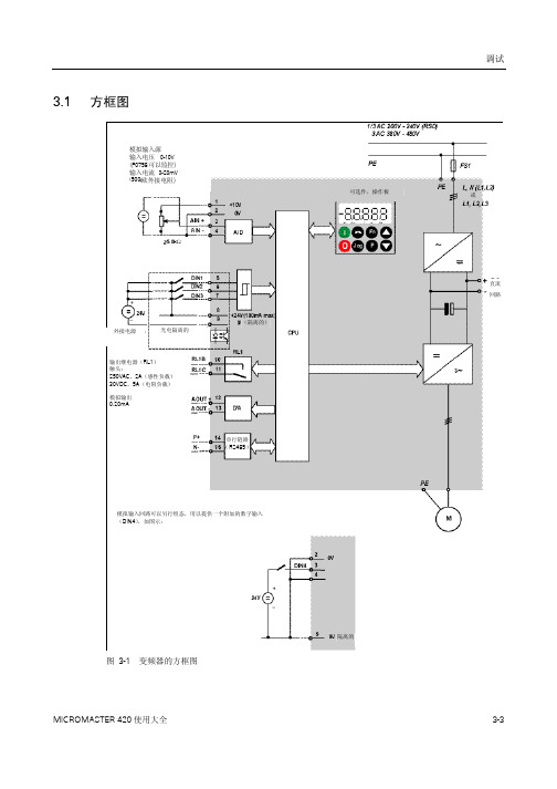
MICROMASTER 420 使用大全
调试
显示/按钮
功能 功能
功能的说明
此键用于浏览辅助信息。 变频器运行过程中,在显示任何一个参数时按下此键并保持不动 2 秒钟,将 显示以下参数值(在变频器运行中,从任何一个参数开始): 1. 直流回路电压(用 d 表示– 单位:V) 2. 输出电流(A) 3. 输出频率(Hz) 4. 输出电压(用 o 表示 – 单位:V)。 5. 由 P0005 选定的数值(如果 P0005 选择显示上述参数中的任何一个(3,
表 3-2 表示由 BOP 操作时的工厂缺省设置值。
提示
♦ 在缺省设置时,用 BOP 控制电动机的功能是被禁止的。如果要用 BOP 进行控制,参数 P0700 应设置为 1,参数 P1000 也应设置为 1。
♦ 变频器加上电源时,也可以把 BOP 装到变频器上,或从变频器上将 BOP 拆卸下来。 ♦ 如果 BOP 已经设置为 I/O 控制(P0700=1),在拆卸 BOP 时,变频器驱动装置将自动停车。
起动S/停tar车t/Stop 反向 Rev 故障复位 Ack
Di数gi字tal输In入puts
A模na拟lo输gu入e Inputs
5.0 k Ω
图3-4 用 SDP 进行的基本操作
3.2.2 用 BOP 或 AOP 进行调试的简要说明
前提条件: 机械和电气安装已经完成。
设置电动机的频率 DIP 开关 2:Off = 50 Hz / ON = 60 Hz
(60 Hz,功率单位:hp。)
¾ DIP 开关 1: 不供用户使用。
图 3-3 DIP 开关
3-4
MICROMASTER 420 使用大全
调试
SBC-支架控制模块数据' 传感器数据 5.2 测试H返本 自动模式 高速 于问题023-隔体单元S

Data sheetThe module contains 8 relays with normally-open contacts for direct or alternating current up to 2 A, 48 VAC. The module is especially suited wherever AC switching circuits with infrequent switching have to be controlled. For space reasons, there is no integrated contact protection.Bus connector Bus interfaceRelayLEDsScrew terminals Relay contactsSupply 24 VDCfor Relay coilsTechnical dataLEDs and connection terminalsIn the manual 27-600_ENG, in the Chapter appendix A.4 relay contacts, are calculation data and wiring suggestions or the relay contacts. These data should be absolutely considered for safe switching and a long life span of the relays.PCD2.A250Digital output module, 2 × 4 relays, 48 VAC/2 A or 50 VDC/2 A, 'make' contact, without contact protectionInstallation instructionsFor reasons of safety it is not permissible to connect low voltages (up to 50 V) and higher voltages (50 … 250 V) to the same module.If a Saia PCD® module is connected to a higher voltage (50 … 250 V), approved components for this voltage must be used for all elements that are electrically connected to the system.Using higher voltage (50 … 250 V), all connections to the relay contacts must be connected on the same circuit, i.e. in such a way that they are all protected against one AC phase by one common fuse. Each load circuit may also be protected individually. .Saia-Burgess Controls AGBahnhofstrasse 18 | 3280 Murten, Switzerland T +41 26 580 30 00 | F +41 26 580 34 ********************|2PP31-503 ENG03 10-2016Technical data and information subject to change.Ordering informationRelay energized (contact closed): LED on Relay reset (contact open): LED off 24 VDC must be connected to the +/- terminals.Output circuits and terminal designationRelay contactsTerminalsone common terminalWatchdog: This module can be used on all base addresses; there is no interaction with the watchdog on the CPUs. For details, please refer to the “Watchdog” section of the manual 26-856_ENG, which describes the correct use of the watchdog in conjunction with PCD2 components.I/O modules and I/O terminal blocks may only be plugged in and removed when the Saia PCD® and the external +24 V are disconnected from the power supply.Accessories。
德拉埃特荷尔达PQ引导SP IP65外壳 - 无显示说明书

SPECIFICATIONSvG UIDEPOWER QUALITY ANALYZERThe Best Combination of Value & Technologyin a PQ Analyzer – Safe, Powerful & Intelligent!Dranetz HDPQ® Guide SPIP65 Enclosure - No DisplayDranetz HDPQ® Guide7” Color, Touch DisplayMADE IN USAG UIDE®G UIDE SPMEASURED PARAMETERS(4) Differential Voltage: 16 bit resolution0-1000Vrms, AC/DC, ±0.1 % reading, <40V ±0.5%FSIEC 61000-4-30 Class A: 60-1000Vrms, ±0.1 % of Udin, range ofRange probe dep., AC/DC, +/- 0.1% reading +/- 0.05% FSFrequency:16-25Hz, 42.5-69Hz, +/- 0.01HzCALCULATED PARAMETERSPower/Energy - 1 Second samplingReal Power (W) - P: meets 0.2S requirements, range probe dep.Apparent Power (VA) - S: meets 0.2S requirements, range probe dep.Reactive Power (var) - Q: meets 0.2S requirements, range probe dep.Power Factor (W/VA) -”true” 1 to 0 to -1Displacement PF 1 to 0 to 1Demand (in W): meets 0.2S requirements, range probe dep.Energy (in Wh): meets 0.2S requirements, range probe dep.Distortion - 200ms, 3 sec, 10 min windowsVthd: 0-100%, +/- 5% for V>=1% Vnom,V Ind Harm: DC, 2-127, +/- 5% for V>=1% VnomIthd: 0-100%, +/- 5% for I>=1% Vnom,I Ind Harm: DC, 2-63, +/- 5% for I>=1% VnomMisc.Pst - 10 minutes: 0.2-10, +/- 0.05 @ Pst=1Plt - 2 hours: 0.2-10, +/- 0.05 @ Pst=1EASE OF USE FEATURESAutomatic SetupsPre-programmed monitoring modesAnswerModules®- Sag/Dip Directivity, PF Cap, MotorDashboards - PQ, Demand & EnergySimultaneous PQ, Demand & EnergyMini ReportSTANDARDS COMPLIANCEPower QualityIEC 61000-4-30 Class A: Edition 2 (2008)IEEE 1159: 2009STANDARDS COMPLIANCE (continued) PowerIEEE 1459: 2000HarmonicsIEC 61000-4-7 Class 1: Edition 2 (2008)IEEE 519: 2014Voltage FlickerIEC 61000-4-15: Edition 2 (2010)IEEE 1453: 2011Compliance/TestingEN 50160: 2010GENERAL SPECIFICATIONSDranetz HDPQ GuideSize: (10”w x 8”h x 2.75”d), (25.4cm x 20.3cm x 7.00cm)Weight: 4.2lbs, 2kgOperating temperature: 0 to 50 deg C (32 to 122 deg F)Storage temperature: -20 to 55 deg C (-4 to 122 deg F)Humidity: 10-90% non condensing3 hours run time on full charge, 3 hours charge timeDranetz HDPQ Guide SPSize: (11”w x 6.5”h x 2.5”d), (27.9cm x 16.5cm x 6.4cm)Weight: 3.2lbs, 1.45kgOperating temperature: -10 to 50 deg C (14 to 122 deg F)Storage temperature: -40 to 85 deg C (-40 to 185 deg F)Humidity: 0-95% non condensing15 minutes run time on full charge, 3 hours charge timeClock accuracy and resolutionInternal: +/- 1 sec/day at 25deg CNTP: +/-10 msecGPS: +/-1 msecAC Adapter: 90-264(max) 50/60HzMemory size: 4GBDisplay: 7” WVGA color graphic, Icon based touch LCD, LED Backlit(Guide only)Languages: English, German, Spanish, French, Italian, Swedish, Finn-ish, Polish, Chinese (traditional and simplified), Thai, KoreanCOMMUNICATIONSEthernet, 802.11 b/g/n WirelessUSB On the GoBluetooth via USB adapterVNC remote controlAndroid® & Apple® AppI12-RevAG UIDE SG UIDE SPEasle and Wire ManagementApplicationsWhether your applic ation requires power quality monitoring, demand/energy monitoring, or both, the powerful feature set of the Dranetz HDPQ® Guide family provides you the tools need-ed to get the job done. Dranetz HDPQ Guide instruments are perfec t for applic ations suc h as PQ surveys, fault rec ording, inrush, motor testing, harmonic analysis, advanced distortion analysis, demand/energy/load studies, and much more. The HDPQ Guide and Guide SP offer the exact same measure-ment features, but in different enc losures that c an meet the needs of a wide variety of applications and work environments. The HDPQ Guide is a portable instrument with a built in 7”, Tablet like LCD display. The same local user interface is also available remotely on a PC, Tablet or Smartphone by using the built in Ethernet or Wi-Fi c ommunic ations and Dran-View 7, or a free VNC remote control App. The HDPQ Guide SP offers the same measurement capabilities and communications, but is housed in an IP65 enclosure without an LCD display, greatly expanding applications into outdoor and harsh environments along with those where an LCD display is undesirable.Advan ced PQ & Energy Capabilities!Dranetz products have a long-standing tradition of having state of the art PQ monitoring capabilities, and the Dranetz HDPQ Guide is no exc eption. HDPQ Guide meets and exc eeds the most stringent industry monitoring standards, including:Power Quality - IEC 61000-4-30 Class A, IEEE 1159Harmonics - IEC 61000-4-7, IEEE 519Voltage Flicker - IEC 61000-4-15, IEEE 1453 – Including Pinst Advanced Energy – IEEE 1459Transient CaptureThe Dranetz HDPQ Guide goes well beyond the requirements of the PQ standards by including transient capture capabilities for voltage and current, such as: transients to 32 microseconds, peak sample transients, and advanced waveshape change tran-sients that can identify changes from cycle to cycle.AnswerModules ® – Smart & Good Looking!Only available from Dranetz, AnswerModules are algorithms that automatic ally identify power quality problems and their sourc e. These diagnostic and reporting tools are based on our decades of analytic al experienc e, benc hmarking, and troubleshooting work. The HDPQ Guide has three built in AnswerModules:Sag/Dip Directivity: Automatically identifies the source of a Sag/Dip as being up stream or downstream from the moni-toring source.Capacitor Switching: Automatically identifies transients as being Power Factor correction transients.Motor Analysis: Enables the PQ p arameters that are imp ortant to motor surveys, and provides a custom dashboard for results.G®The Best Combination of Value & Technology in a PQ Analyzer - Safe, Powerful & IntelligentPower Quality instruments are no different than anything else – you get what you pay for – you just get much more from the Dranetz HDPQ ® Guide than with any other instrument in its class!The Dranetz HDPQ ® Guide SP offers the same value, but in a hardened IP65 enclosure.Safe Remote Accessibility via Dran-View ® 7, Apps and VNCDON’T RISK YOUR SAFETY! The Dranetz HDPQ Guide comes with a standard Ethernet port, built-in Wireless, and USB Bluetooth commu-nications that allow you to easily comply with today’s arc flash and other safety standards. Simply install your HDPQ Guide, close the cabinet door, and use your Tablet, Smartphone, PC, or MAC computer to remotely control monitoring and review data. Fully control your instrument remotely, and see exactly what’s on the local 7” display by using Dranview 7 or a free VNC program or App for PC, MAC, Apple and Android devices. Or, you can also use the Dranetz HDPQ App for Apple and Android devices to remotely view a real-time dashboard, scope mode, or remotely configure the instrument using automatic setups. For local access, there’s also a built-in USB port to copy data to a USB drive or directly to your computer using a Plug-N-Play connection.Dashboard Display Demand & Energy TrendEasy to Use Intuitive User InterfaceWith their innovative packaging and 7” wide screen color touch display, the Dranetz HDPQ family of instruments are the most powerful and easiest to use power monitoring instruments available. Like your tablet computer, simply useyour finger or stylus to easily navigate the intuitive, icon-based user interface. Setting up the HDPQ Guide is made easy with automatic setups that detect the cir-cuit type, voltage, etc. and configure the instrument in seconds with typical indus-try settings. For customized setups, use the manual Wizard mode that guides you step-by-step through each setup. During monitoring, real time measurements can be viewed in many ways, including a color-coded reporting Dashboard, and meter/scope/phasor/harmonics displays. Recorded data can be viewed over time by using the timeline and event list displays, and also by using compliance reports, such as EN 50160.Demand & Energy SurveysManaging energy and reducing related expenses is always of par-amount importance, and in many cases is a corporate mandate. In addition to industry-best power quality monitoring capabilities, all of the Dranetz HDPQ family products also have extensive demand and energy monitoring capabilities for both long and short duration surveys. Unlike other lesser capable instru-ments, there’s more than enough horsepower to perform complete PQ and energy surveys simultaneously – it’s your choice to survey for PQ, Energy, or both. Seeing results is easy when using the energy and demand Dashboard reports that display real time and accumulated readings in a color-coded reporting format. There’s also a billing report that includes your energy rates, including time of use. You can also upload your data to our Dran-View 7 software for viewing, reporting, and printing via PC.Reporting & AnalysisThe Dranetz HDPQ Dashboard takes the guess work out of knowing what the instru-ment has recorded. The Dashboard is a color coded alarm panel with boxes that represent different event types (Sags, Swells, Transients, THD, etc.). Each box shows the real time me-tered values for the event type, and is color coded to indicate if events of that type have been recorded.Dran-View ® 7 is our industry leading Win-dows-based software program that enables power professionals to simply and quickly visualize and analyze power monitoring data. Dran-View enhances the Dranetz HDPQ Visa instruments with its VNC remote control, down-loading, and advanced analytical capabilities. It is successfully used by thousands of customers around the world, and has become the industry leading power management software tool. Dran-View is easy to use, yet adds tremendous value and power to our Dranetz HDPQ family of instruments. Of course Dran-View can trend and list data recorded by the instrument, but it also includes a built in report writer, allows you to embed pictures, provides mathematical analy-sis tools, and even includes a rescue kit to help correct connection mistakes.Dran-View ® 7Dranetz HDPQ Live VNC & DownloadDranetz HDPQ Guide SPIP65 Enclosure - No DisplayDranetz HDPQ GuidePortable with 7” DisplayV & I Connections• 1000V CAT III (600V CAT IV)• AC/DC Differential Voltage & Current Inputs • DRANFLEX CT’s powered by the instrumentInnovative Package & Wide Screen7” color, wide screen touch display. 40% largerthan before - the largest in the industry!G UIDE SG UIDE SP。
PME快速入门手册

PME现场调试操作手册一、综述兴化城南污水厂,采用了GE RX3i系列PLC,经查询资料,该系列PLC应该属于GE换代产品,从外观到性能都很像老款的GE90-30系列PLC,属于中档产品,可以用于实时性不是很高但是需要长期连续运行的工程现场。
RX3i系列PLC采用的编辑软件为GE Proficy Machine Edition(简称PME),需要8.0及以上编程软件。
二、常用菜单打开PME程序会显示下面的几个菜单,主要用到的都在这里,比如左侧的XHCN,项目根目录,PLC1~PLC5和SLC1~SLC6是我定义的11个PLC的工程名,下面的Message是主要的反馈信息,这些信息在调试的时候非常重要、一定要仔细阅读,会有利于系统调试。
最右边是梯形图常用命令。
三、基本操作1、打开工程第一次打开PME或者点File—Open,均会出现下列界面自上而下分部是创建一个空工程、创建一个ME模板工程和打开已存在最近打开过的工程。
这里的XHCN是我自己创建的工程。
点OK打开项目2、工程首页3、创建工程节点在XHCN上点击右键,会出现Add Target菜单,选择到PAC RX3i系统系统会自动在最下面生成一个PAC项目,并自动创建相关硬件配置、程序模块等基本模块4、配置硬件在导航页,点击Hardware Configuration,可以对硬件参数进行配置,这里如果有的CPU含网口,则必须在配置完CPU后填写IP地址信息,否则将会硬件报错。
四、系统调试1、调试参数配置在工程节点上点右键,选择最下面的Porperties弹出一个小对话框这里有选定工程的相关参数,拉动滑块到最下面,有一个Physical Port选项,这个选项是编程软件与PLC的通信端口,默认是COM1,需要调整到ETHERNET,并填入PLC的IP地址2、设置活动工程在进行PLC调试时,每次只能对一个PLC进行调试,所以,需要在调试时设置活动工程,在需要设置为活动工程的工程上点右键,选择Set as Active Target,选择后,对应的工程会变成加宽的黑色字体。
SN74LVC1G57DBVR,SN74LVC1G57DBVR,SN74LVC1G57DBVR,SN74LVC1G57DCKR, 规格书,Datasheet 资料

Reel of 3000 SN74LVC1G57DBVR
SOT (SC-70) – DCK
Reel of 3000 SN74LVC1G57DCKR
SOT (SOT-563) – DRL QFN – DRY(3) µf 4000 Reel of 5000 Reel of 5000
Submit Documentation Feedback
3
SN74LVC1G57
SCES414M – NOVEMBER 2002 – REVISED OCTOBER 2011
Absolute Maximum Ratings(1)
over operating free-air temperature range (unless otherwise noted)
SN74LVC1G57DRLR SN74LVC1G57DRYR SN74LVC1G57DSFR
TOP-SIDE MARKING(2)
_ _ _CL_
CA7_ CL_ CL_ CL CL
(1) Package drawings, standard packing quantities, thermal data, symbolization, and PCB design guidelines are available at /sc/package.
安森美 MBR0540T1-D 肖特基功率整流器 表面贴装 0.5 A 40 V SOD-123 数

MBR0540T1G,NRVB0540T1G,MBR0540T3G,NRVB0540T3GSchottky Power Rectifier, Surface Mount,0.5 A, 40 V, SOD-123 PackageThe Schottky Power Rectifier employs the Schottky Barrier principle with a barrier metal that produces optimal forward voltage drop−reverse current tradeoff. Ideally suited for low voltage, high frequency rectification, or as a free wheeling and polarity protection diodes in surface mount applications where compact size and weight are critical to the system. This package provides an alternative to the leadless 34 MELF style package.Features∙Guardring for Stress Protection∙Very Low Forward V oltage∙Epoxy Meets UL 94 V−*********∙Package Designed for Optimal Automated Board Assembly∙AEC−Q101 Qualified and PPAP Capable∙NRVB Prefix for Automotive and Other Applications RequiringUnique Site and Control Change Requirements∙All Packages are Pb−Free*Mechanical Characteristics∙Device Marking: B4∙Polarity Designator: Cathode Band∙Weight: 11.7 mg (approximately)∙Case: Epoxy Molded∙Finish: All External Surfaces Corrosion Resistant and Terminal Leads are Readily Solderable∙Lead and Mounting Surface Temperature for Soldering Purposes: 260︒C max. for 10 Seconds∙ESD Rating:♦Human Body Model = 3B♦Machine Model = C*For additional information on our Pb−Free strategy and soldering details, please download the ON Semiconductor Soldering and Mounting Techniques Reference Manual, SOLDERRM/D.B4= Device CodeM= Date CodeG= Pb−Free PackageSCHOTTKY BARRIERRECTIFIER0.5 AMPERES, 40 VOLTSSOD−123CASE 425STYLE 1MARKING DIAGRAMDevice Package Shipping†ORDERING INFORMATIONMBR0540T1G SOD−123(Pb−Free)3,000/T ape & Reel(8 mm Tape, 7” Real)MBR0540T3G SOD−123(Pb−Free)10,000/T ape & Reel(8 mm Tape, 13” Real)†For information on tape and reel specifications, including part orientation and tape sizes, please refer to our T ape and Reel Packaging Specifications Brochure, BRD8011/D.(Note: Microdot may be in either location)NRVB0540T1G SOD−123(Pb−Free)3,000/T ape & Reel(8 mm Tape, 7” Real)NRVB0540T3G SOD−123(Pb−Free)10,000/T ape & Reel(8 mm Tape, 13” Real)1MAXIMUM RATINGSRatingSymbol Value Unit Peak Repetitive Reverse Voltage Working Peak Reverse Voltage DC Blocking VoltageV RRM V RWM V R 40VAverage Rectified Forward Current (At Rated V R , T C = 115︒C)I O 0.5A Peak Repetitive Forward Current(At Rated V R , Square Wave, 20 kHz, T C = 115︒C)I FRM 1.0A Non −Repetitive Peak Surge Current(Surge Applied at Rated Load Conditions Halfwave, Single Phase, 60 Hz)I FSM 5.5A Storage/Operating Case Temperature Range T stg , T C −55 to +150︒C Operating Junction Temperature T J −55 to +150︒C Voltage Rate of Change (Rated V R , T J = 25︒C)dv/dt1000V/m sStresses exceeding Maximum Ratings may damage the device. Maximum Ratings are stress ratings only. Functional operation above the Recommended Operating Conditions is not implied. Extended exposure to stresses above the Recommended Operating Conditions may affect device reliability.THERMAL CHARACTERISTICSCharacteristicSymbol Value Unit Thermal Resistance − Junction −to −Lead (Note 1)Thermal Resistance − Junction −to −Ambient (Note 2)R tjl R tja118206︒C/W1.Mounted with minimum recommended pad size, PC Board FR4.2. 1 inch square pad size (1 X 0.5 inch for each lead) on FR4 board.ELECTRICAL CHARACTERISTICSCharacteristicSymbol ValueUnit Maximum Instantaneous Forward Voltage (Note 3)v FT J = 25︒C T J = 100︒CV(i F = 0.5 A)(i F = 1 A)0.510.620.460.61Maximum Instantaneous Reverse Current (Note 3)I R T J = 25︒CT J = 100︒C m A (V R = 40 V)(V R = 20 V)201013,0005,0003.Pulse Test: Pulse Width ≤ 250 m s, Duty Cycle ≤ 2.0%.101.00.1Figure 1. Typical Forward VoltageFigure 2. Maximum Forward Voltagev F , INSTANTANEOUS FORWARD VOLTAGE (VOLTS)101.0V F , MAXIMUM INSTANTANEOUS FORWARD VOLTAGE (VOLTS)i F , I N S T A N T A N E O U S F O R W A R D C U R R E N T (A M P S )0.1I F , I N S T A N T A N E O U S F O R W A R D C U R R E N T (A M P S )Figure 3. Typical Reverse CurrentFigure 4. Maximum Reverse Current40V R , REVERSE VOLTAGE (VOLTS)100E-31.0E-3100E-610E-61.0E-6100E-9V R , REVERSE VOLTAGE (VOLTS)I 102030, R E V E R S E C U R R E N T (A M P S )R 40I 102030, M A X I M U M R E V E R S E C U R R E N T (A M P S )R10E-3100E-31.0E-3100E-610E-61.0E-6100E-910E-3Figure 5. Current DeratingFigure 6. Forward Power DissipationT L , LEAD TEMPERATURE (︒C)0.80.40.30.20.10I O , AVERAGE FORWARD CURRENT (AMPS)0.100.450.400.350.150.0500.4, A V E R A G E F O R W A R D C U R R E N T (A M P S )I O 0.50.20.30.50.80.10P F O , A V E R A G E P O W E R D I S S I P A T I O N (W A T T S )0.60.70.300.200.250.60.7Figure 7. Capacitance Figure 8. Typical Operating Temperature Derating*V R , REVERSE VOLTAGE (VOLTS)10010V R , DC REVERSE VOLTAGE (VOLTS)118114112110C , C A P A C I T A N C E (p F )T 116120126, D E R A T E D O P E R A T I N G T E M P E R A T U R E ( C )J ︒* Reverse power dissipation and the possibility of thermal runaway must be considered when operating this device under anyreverse voltage conditions. Calculations of T J therefore must include forward and reverse power effects. The allowable operatingT J may be calculated from the equation:T J = T Jmax − r(t)(Pf + Pr) where r(t) = thermal impedance under given conditions,Pf = forward power dissipation, and Pr = reverse power dissipationThis graph displays the derated allowable T J due to reverse bias under DC conditions only and is calculated as T J = T Jmax − r(t)Pr, where r(t) = Rthja. For other power applications further calculations must be performed.122124Figure 9. Thermal Response Junction to LeadFigure 10. Thermal Response Junction to Ambient1000.10.00001T, TIME (s)1E+001E-011E-021,000R 0.00010.0010.01 1.0101E-03, T R A N S I E N T T H E R M A L R E S I S T A N C E (N O R M A L I Z E D )(T )T, TIME (s)1E+001E-011E-02R 1E-03, T R A N S I E N T T H E R M A L R E S I S T A N C E (N O R M A L I Z E D )(T )1000.10.000011,0000.00010.0010.01 1.010SOD−123CASE 425−04ISSUE GDATE 07 OCT 2009SCALE 5:1NOTES:1.DIMENSIONING AND TOLERANCING PER ANSIY14.5M, 1982.2.CONTROLLING DIMENSION: INCH.DIM MIN NOM MAXMILLIMETERSINCHESA0.94 1.17 1.350.037A10.000.050.100.000b0.510.610.710.020c1.600.150.055D 1.40 1.80E 2.54 2.69 2.840.100---3.680.140L0.253.860.0100.0460.0020.0240.0630.1060.1450.0530.0040.0280.0710.1120.152MIN NOM MAX3.56H E---------0.006------------GENERICMARKING DIAGRAM**For additional information on our Pb−Free strategy and solderingdetails, please download the ON Semiconductor Soldering andMounting Techniques Reference Manual, SOLDERRM/D.SOLDERING FOOTPRINT**This information is generic. Please refer to device datasheet for actual part marking. Pb−Free indicator, “G” ormicrodot “ G”, may or may not be present.XXX= Specific Device CodeM= Date CodeG= Pb−Free Package1STYLE 1:PIN 1. CATHODE2. ANODE0.910.036ǒmminchesǓSCALE 10:1------q001010°°°°(Note: Microdot may be in either location) MECHANICAL CASE OUTLINEPACKAGE DIMENSIONSON Semiconductor and are trademarks of Semiconductor Components Industries, LLC dba ON Semiconductor or its subsidiaries in the United States and/or other countries.ON Semiconductor reserves the right to make changes without further notice to any products herein. ON Semiconductor makes no warranty, representation or guarantee regarding the suitability of its products for any particular purpose, nor does ON Semiconductor assume any liability arising out of the application or use of any product or circuit, and specifically disclaims any and all liability, including without limitation special, consequential or incidental damages. ON Semiconductor does not convey any license under its patent rights nor thePUBLICATION ORDERING INFORMATIONTECHNICAL SUPPORTNorth American Technical Support:Voice Mail: 1 800−282−9855 Toll Free USA/Canada Phone: 011 421 33 790 2910LITERATURE FULFILLMENT :Email Requests to:*******************onsemi Website: Europe, Middle East and Africa Technical Support:Phone: 00421 33 790 2910For additional information, please contact your local Sales Representative。
Texas Instruments TMDSEMU200-U XDS200 USB Debug Pr

TMDSEMU200-UTexas Instruments TMDSEMU200-U XDS200 USB DebugProbe is the JTAG debug probes (emulators) for debuggingTI embedded devices. This probe is designed to deliver goodperformance as compared to the low-cost XDS100 and the highperformance XDS560v2. The XDS200 is the balanced solutionto debug TI microcontrollers, processors, and wireless devices.The XDS200 is designed to replace the aging XDS510 familyof JTAG debuggers with higher JTAG data throughput, addedsupport for ARM Serial Wire debug modes and reduced cost.All XDS200 variants feature a standard TI 20-pin connector as the primary JTAG connectivity to the target. In addition to that, all variants also feature modular target configuration adapters for TI and ARM standard JTAG headers. The XDS200 supports the traditional IEEE1149.1 (JTAG), IEEE1149.7 (cJTAG) as well as ARM’s Serial Wire Debug (SWD) and Serial Wire Output (SWO) and operates with interface levels from +1.5V to 4.1V.• The XDS200 is the latest family of JTAG debug probes (emulators) for TI processors • Designed to deliver good performance and the most common features that place it between the low cost XDS100 and the high performance XDS560v2, the XDS200 is the balanced solution to debug TI microcontrollers, processors and wireless devices • The XDS200 is designed to replace the aging XDS510 family of JTAG debuggers with higher JTAG data throughput, added support for ARM Serial Wire debug modes and reduced cost• Following the trend for space reduction on modern TI development boards, all XDS200 variants feature a standard TI 20-pinconnector as the primary JTAG connectivity to the target• In addition to that, all variants also feature modular target configuration adapters for TI and ARM standard JTAG headers (the offer of adapters varies per model)• The XDS200 supports the traditionalIEEE1149.1 (JTAG), IEEE1149.7 (cJTAG) as well as ARM’s SWD and SWO and operates with interface levels from +1.5V to 4.1V XDS200 USB Debug ProbeProduct Overview 07-12-2021For the most up-to-date information, visit or the supplier’s website.• IEEE1149.7 or Compact JTAG (cJTAG) is a major improvement over the traditional JTAG, as it supports all its features while usingonly two pins, and is available in selected TIwireless connectivity microcontrollers• The SWD is a debug mode that also uses two pins and transfers data at a higher clock rate when compared to JTAG• The SWO adds one more pin that allows performing simple Trace operations onselected Cortex M4 microcontrollers• All XDS200 models support a USB2.0 High Speed (480Mbps) connection to the host,with some models also supporting Ethernet10/100Mbps• Also, some models support powerconsumption monitoring on the target board • The XDS200 family is fully compatible with TI’s Code Composer Studio IDE• This combination gives a complete hardware development environment which includes an Integrated Debug Environment, Compiler, and full hardware debugging and Trace capability on selected TI microcontrollers, processorsand wireless connectivity microcontrollers • XDS200 comes in a package consisting of:• XDS200 debug pod• TI 20-pin to TI 14-pin converter adapter• TI 20-pin to ARM 20-pin converter adapter • TI 20-pin to ARM 10-pin converter adapter • USB2.0 cable• Quick start guide • Devices supported:• SimpleLink TM MCUs (CC13xx, CC26xx, CC3x, MSP432)• C2000TM microcontrollers• TM4C microcontrollers• Hercules TM microcontrollers• Sitara (AM335x, AM43xx, AM57xx,AM64xx, AM65xx, AMIC1xx) AutomotiveSoCs (TDAx ADAS, DRAx infotainment)• mmWave sensors (IWR/AWR14xx, IWR/ AWR16xx, IWR68xx)• OMAPL13x SoCs• C674x and C66x (Keystone I) Floating point DSPs• C642x and C645x• 66AK2 and TCI66x Multicore DSP + Arm®SoCs (Keystone II)• C55x Low-power DSPs• UCD3x digital power devices• PGA970 SoC• Other TI SoCs with PRU, C674x, C66xx, Cortex M, Cortex R, and Cortex A cores • Devices NOT supported:• MSP430TM microcontrollers• AWR12xx mmWave sensors• C54x• C62x, C670x, C671x, C672x, C640x, and C641x• F24x/C24xTMDSEMU200-UTo learn more, visit https:///new/texas-instruments/ti-tmdsemu200-u-debug-probe/。
松下伺服,台达,西门子变频器参数(应用版)

1.0横移伺服驱动器的设定A4注:其它参数都是缺省值。
1.1上下伺服驱动器的设定A4注:其它参数都是缺省值。
、松下A5(MCDHT3520E)伺服器相关参数设置(用PANATERM VER5.0软件调试)(配USB mini-B通讯线连接到驱动器X1)1,Pr-002:4 (PANATERM软件运行调试机械磨合好刚性,增益之后,设为0).4变为02,Pr-003:4-13 (根据机械手运行后的平稳情况而定,近几台机器都是横移为13、升降为11----4)3,Pr-004:(软件自动调,一般为100-600)4,Pr-007:35,Pr-008: 横移为2020、升降为2000(PLC程序中相对A4的距离和速度都*10),Pr-010则无效6,Pr-100, Pr-101, Pr-102等跟增益有关的参数都是在Pr-002不为0的情况下,运行之后会自动变化的7,伺服-ON即激磁,在PLC程序里,必须设计为只要无报警,则长通;刹车也是。
8,参考英利湿化学J588右进(11#)(S-10-200)或J588左进(12#)(S-10-199)松下伺服电机A5软件下载/描述:由于软件过大,摧荐上松下网站下载,复制以下网址就加入到讯雷等下载软件下载即可/setupsoft/setup.exe运行PANATERM ver 5.0 软件1.2 1、3、4、6、7槽/配碱搅拌泵变频器的设定(台达VFD-M与触摸屏MT4500T通信)EviewMT4500T屏(20画面)的1-6槽循环泵数值输入元件的输入地址中的:HMI都是0,PLC是5/6/7/8/9,地址类型都是4X,地址都是8194,8194=2001H+1,2001H是VFD变频器参数中P92中取03时,MODBUS RTU模式,资料格式8N2中对变频器的命令2001H频率命令,2001H十六进制换为十进制=8193,因触摸屏地址是从0开始的所以需加1。
VFD变频器的输出COM与M0由Y232-Y237直接控制输出。
MOONS' LED驱动器说明书

MU050S150BQI201 SPECIFICATIONS REVISION: A0oc No.: MSSD-6420 A0 LED DRIVER SPECIFICATIONSPart Description: Input:90AC~305V AC,Customer’s Part Number:MOONS’ Part Number: MU050S150BQI201Customer:Company:Department:Approved by:Date:EDITED: DATE:CHECKED: DATE:STANDARD: DATE:APPROVED: DATE:SHANGHAI MOONS’ AUTOMATION CONTROL Co., LTD.MU050S150BQI201 SPECIFICATIONS REVISION: A0 REVISIONS:Approved Rev. Date Descriptions ECONo. Edited CheckedA0 2017-04-20 New release Nisem◆Input voltage: 100-277Vac ,140-388Vdc◆Built-in active PFC function 0.95 Typ.◆High efficiency: up to 87% Typ.◆Constant current, 2 channels output ◆Output current can be set from 150~1500mA ◆AUX output 12V,150mA ◆Protection: OVP, SCP, OTP◆According with UL Class2、EN SELVEfficiency(230Vac)Efficiency(120Vac)Voltage RangeRated Input Voltage Frequency Range (Hz)Power Factor THDAC Current(Typ.)Inrush Current(Typ.)Input Power (W)Standby power (W)Leakage Current(max.)Output Voltage Range (V)Note.1Output Current Range(mA)Rated Power (W)Output channelsRipple Current (PK-PK)/AV Current Tolerance Line Regulation Load Regulation Setup, Rise Time AUX outputDimming Control Open circuit protection(V)Short CircuitOver Temperature Operating Temp.Operating HumidityStorage Temp., Humidity VibrationIngress Protection RatingIsolation Resistance EMC Emission EMC Immunity Life time MTBFDimension WeightVersion:A0MU050S150BQI201 Intelligent indoor LED driver■ SpecificationModel■ Features ◆2 channels 0-10V control◆4 in 1:Tunable white(1500-6500K).Dim to warm(1500-3200K),Solo dimming, Dual dimming0.55A MAX at 120VAC , 0.3A MAX at 230VAC50/60<20%, at 100~277Vac 50/60Hz input, with 50%~100% load conditions87%(Typical )at 100% load conditions>0.9 at 100~277Vac 50/60Hz input, with 50%~100% load conditions 90-305Vac , 126-427Vdc 0.75mA at 277Vac 60Hz input150-1500.Support hot plug, without overshoot current .(MU050S150BQI201 )<10A at 100~277Vac input 25℃ cold start at 100% conditions .for more details in the attached graph<0.5S @120V/60HZ, 230V/50HZ210% max, at output 700~1500mA conditions60(max)8-55<0.5W at input 120Vac, 230Vac Environment20~95%RH, non-condensing -25~+50℃ ( TBD)110℃±20%FCC Part 15 ClassB ,EN55015,EN61000-3-2 Class C ,EN61000-3-350(max)60Isolated 0-10V dimming / 0.1%Io~100%Io ref. Dimming module diagram and dimming curvePower supply stops output, recovers automatically when fault condition removed±5%87%(Typical )at 100% load conditions 408x 30 x 21 mm (LxWxH )±3%ProtectionInput100-277Vac , 140-388VdcNote.1: refer to V/I curve>50000@Tc =70℃(TBD) at 100% load conditions-40~+85℃, 10-95%RHPage 3 of 8I/P-O/P ,I/P-FG,O/P-FG:100M Ohms/500VDC/25℃/70%RH300,000 hours, measured at full load, 25℃ ambient temperature MIL-HDBK-217F(25℃)Safety & EMCEN61000-4-2,3,4,5,6,8,11,EN61547(Surge L,N-FG 2.5KV ,L-N 2.5KV )OthersUL8750, UL1012,UL1310 Class 2, CAN/CSA-C22.2No.107.1-01,EN61347-1, EN61347-2-131.5KV TBDAll Rights Reserved 2017-03-27 1.5KV 1.5KV1.875KV 1.5KV 1.5KVOutput12V± 3% ,150mA max10~500Hz, 5G 12min/cycle, period for 72min each along X 、Y 、Z axis±1%IP20Isolation Input Output Dimming interface Enclosure Enclosure No applicable Input No applicable 3.75KV 1.875KV Output 3.75KV No applicable 1.5KV Safety StandardDimming interface 1.5KV 1.5KV No applicableVersion:A0All Rights Reserved 2017-03-27Derating CurveSHANGHAI MOONS' AUTOMATION CONTROL CO., LTD.Tel: +86 (0)21 52634688 Website: Derating CurvePage 4 of 8■ CurveV/I CurveTBDTBDVersion:A0 ■ CurvePF VS. Load CurveTHD VS. Load CurveTBDTel: +86 (0)21 52634688 Website: Efficiency VS. Load CurveAll Rights Reserved 2017-03-27Page 5 of 8Input voltage120VAC 220VAC277VACTBD120220277163034213845264756325970407487Version:A0Tel: +86 (0)21 52634688 Website: Inrush current waveformAll Rights Reserved 2017-03-27Page 6 of 80-10V dim CurveIpeak■ Curve1.15Time@50% of Ipeak50us 2.4650us ItemInput voltage [VAC]Max number of drivers per MCB60usInrush current information Max. number of drivers MCB B type 10A MCB B type 13A MCB B type 16A MCB B type 20A MCB B type 25A2.851. MCS interface(MCS+/MCS-)●MCS+ interface voltage 15V●Max current setting(each step is 1 mA), default driving current defined as 350mA.●Log or linear dimming curve,default setting is linear.●NTC thermal management protects LED lamp,default setting is 70℃.●update Online,use smart key to connect PC and the driver to update the firmware.●When changed to any dimming level, flicker wouldn't occur,dimming would be achieved smoothly.●In the range of 300~1500mA,the current operating in continuous mode; In the range of 0~300mA,the current operating in PWM dimming mode, and the PWM frequency 4.8KHZ.3. Guide for setting driver’s parametersTouch settingProgram driver’s parameters quickly and easily through Near Field Communication. Software download link:/SouProduct/UCenter/M_Search/Software_view.aspx?MATNR=Touch%20Setting&rnd=2119Driver’s parameters can be set through SmartkeyII and Smartkey Network.What’s more,driver’s firmware can be updated through this tool.Softwar/SouProduct/UCenter/M_Search/Software_view.aspx?MATNR=Smartkey%20Network&rnd=21194. Tunable white, Dim to warm , Solo dimming , Dual dimming function introductionCH1CH2CH1CH2Solo dimming Dual dimming Version:A0●Touch Setting●Smartkey NetworkCold color channel Warm color channel All Rights Reserved 2017-03-27Page 7 of 8One 0-10V port control two output channels MURATA NTC ManufacturerVISHAY NTCLE100E3473NTCS0805e4473JXT NCP21WB473J03RA VISHAY 2. Dimming performanceNTC Model NO.MU050S150BQI201 Intelligent indoor LED driver■ Application of introductionNTCcompatibilitylist Two 0-10V ports control two output channelsTunable whiteCold color channel Control port DIM+CCTWarm color channel Dim to warm Control portDIMDimensions(Unit:mm)Port:Version:A0Normal connection usingSpecial connection usingRoHS Compliance:Our products comply with the European Directive 2002/95/EC, calling for the elimination of lead and other hazardous substances from electronic products.SHANGHAI MOONS' AUTOMATION CONTROL CO., LTD.Add: No.168, Mingjia Road, Minbei Industrial Park, Shanghai 201107, P.R.ChinaTel: +86 (0)21 52634688 Website: ■ Mechanical SpecificationAll Rights Reserved 2017-03-27Page 8 of 8MU050S150BQI201 Intelligent indoor LED driverGet larger output current through parallel connection.Support common anode connection.。
R.P.S. Corporation 34 产品系列说明书

3
4 18
16
17
SIDE BROOM MOTOR ASSY P/N 4-425
34 Parts Manual V3.1
Item
Part No.
1
4-111
2
4-113
3
4-220
4
4-223
5
4-376
6
4-378
7
4-381
8
4-385
9
4-386
10
4-402
11
4-404
12
4-436
13
Description MAIN BODY R. INNER SIDE PANEL SIDE BROOM MOTOR BROOM SAFETY DRIVE CPLG BROOM LIFT LEVER BROOM LIFT SHAFT LIFT LEVER BASE, RT LIFT LEVER COLLAR LIFT LEVER SPRING SIDE BROOM POLYPROPYLENE SIDE BROOM CLUTCH PLATE ADJ. BROOM LIFT BROOM MOUNTING BLOCK SIDE BROOM ARM BROOM RETAINING PLATE BROOM MOTOR MOUNT BROOM SHAFT DRIVE TUBE BEARING GROMMET-3/8 ID X 1-1/2 OD X .375 HANDLE GRIP SIDE BROOM LONG LINK ADJUSTMENT KNOB RIGHT FLOOR SEAL RH SEAL STRIP 3/8" X 1 1/4" SPRING PIN 1/4" X 1 1/2" CLEVIS PIN 1/4" X 1 1/4" SPRING PIN FB CASHD 1/4"-20 X 1/2" 1/2" X 1" CLEVIS PIN HCN 1/4"-20 SSS CP 1/4"-20 X 3/8" NYLOK #10-32 NYLOK 1/4"-20 HITCH PIN CLIP 9 HCS 1/4"-20 X 1/2 SS" HN 5/16"- 18 SS NYLOK 5/16" - 18 SS FW 5/8 ID X 1-1/2 OD SS LW 1/4" SS PPH #10-32 X 5/8" SS FHP 1/4"- 20 X 1-3/4" PPH SMS #8 X 3/4" SS #4 HAIR PIN HCS M6-1.0 X 14 SS 3/8" X 1 1/2" CLEVIS PIN
Parker SSD Drives PMAC电机Alignment for C005 Pos Fbk
Application NoteC005 Pos Fbk Alignment for PMAC motorsHA502487C005_002AC30P/D V2.13 onwardsCopyright 2018 Parker SSD Drives, a division of Parker Hannifin Ltd.All rights strictly reserved. No part of this document may be stored in a retrieval system, or transmitted in any form or by any means to persons not employed by a Parker SSD Drives company without written permission from Parker SSD Drives, a division of Parker Hannifin Ltd . Although every effort has been taken to ensure the accuracy of this document it may be necessary, without notice, to make amendments or correct omissions. Parker SSD Drives cannot accept responsibility for damage, injury, or expenses resulting therefrom.iRequirementsIntended UsersThis Application Note is to be made available to all persons who are required to install,configure or service equipment described herein, or any other associated operation.The information given is intended to enable the user to obtain maximum benefit from theequipment.Application AreaThe equipment described is intended for industrial motor speed control utilising AC induction orAC synchronous machines.PersonnelInstallation, operation and maintenance of the equipment should be carried out by qualifiedpersonnel. A qualified person is someone who is technically competent and familiar with allsafety information and established safety practices; with the installation process, operation andmaintenance of this equipment; and with all the hazards involved.HazardsRefer to the Safety Information given at the front of the Product Manual supplied with everyParker SSD Drives product.iiC005P OS F BK A LIGNMENT FOR PMACM OTORSAbstractThis Application Note gives information and how to use the Pos Fbk Alignment feature to align position frommotor feedback to the PMAC motor back EMF. This is required to run the PMAC motor in Vector Control mode. Pre-RequisiteThe pre-requisites are :- a AC30 drive- a feedback attached to the motor with the associated feedback option fitted into the drive.Parameters described below are part of PMAC Motor Data and Pos Fbk Aligmnent. IntroductionBy definition, the motor Vector Control is based on the assumption that the back EMF is crossing the 0V line in a positive direction when the electrical position is also crossing the 0° line in a positive way. Another requirement is to insure a positive ‘encoder/resolver’ rotation with a positive electrical motor rotation ( U, V, W ).1The Pos Fbk Alignment feature is used to automatically calculate any offset between the Zero encoder absolute position and the motor back EMF, as well as selecting the correct wiring of the motor ( U, V, W sequence ) with the encoder position.The feature needs to be run at least once with a PMAC motor associated to an absolute encoder type.The feature needs to be run after each power cycle with a PMAC motor associated to a relative encoder type (pulse encoder for example ). In that case, the absolute position information is lost by the power cycle and thealignment is required after power ON.The feature is run on a motor free to rotate, no load attached to the motor shaft.Regardless of the Alignment Method selected, the motor should move during the sequence.Pos Fbk Alignment operation2 Methods can be selected to align feedback and motor.Alignment Method = MANUALThe motor is moved to an electrical position corresponding to the motor phase selected by Alignment On Motor parameter.This electrical position depends on the PMAC Wiring type selected and on the real motor phase wiring.PMAC Encoder Offset is calculated by looking at real position from the active encoder compared to theoretical position where the motor is.So, it depends also on the encoder settings ( inverted or not ).For standard connections ( correct U, V, W motor wiring sequence and position from encoder varying in a positive way looking at the motor front shaft ), position offset is extracted and written back into PMAC Encoder Offset.Correct connection of the encoder means that a clockwise rotation of the motor front shaft equals a positiveposition variation.Correct motor wiring means phase U, V, W rotating in a correct sequence for a clock wise rotation of the motor front shaft.Considering a standard connection, the following table gives possible encoder and PMAC Wiring settings and results on speed control :** Looking the front shaft of the motor23*** The motor is uncontrolled. It could overspeed, be stalled, or running at constant speed without any control.Alignment Method = AUTOMATICIn case of a correct wiring of encoder and/or motor phases, the sequence is as follows :Current%Elec pos 1 2 3 4 5 6 7 8 9 10 11 12States 210°-30°90°During the final state ( 11 ) , the Alignment Offset is automatically calculated and is passed back to 1808 PMAC Encoder OffsetAlso 1809 PMAC Wiring is set to STANDARDIn the case of a wrong wiring of encoder and/or motor phases, the sequence is as follows :Current%Elec pos 1 2 3 4 5 6 7 8 9 10 11 12 13 14 15 16 17 18States 210°-30°90°From State 4 to 9, a wrong direction as been detected, and the direction should be reverted. Alignment Direction is set to REVERSE.During the final state ( 17 ), the Alignment Offset is automatically calculated and is passed back to 1808 PMAC Encoder OffsetAlso 1809 PMAC Wiring is set to REVERSE.In that case, the direction of motor rotation has been changed during the Pos Alignment sequence. Please verify if the new direction is compatible with your application.If you want to change it, please change the Invert parameter of the active encoder used to control the motor and run again the Pos alignment sequence.Setting up Alignment Method = DIRECTION TEST allows to verify the direction of positive electrical position by slowly rotating the motor. A correct wiring of the motor phases should turn the motor in a clockwise direction looking at the front shaft of the motorThe motor is slowly rotated with the following sequence U, V, W, U, V, W…..It allows to verify the rotation direction and detect any wiring inversion on the motor phases.Active encoder Invert parameter has no effect during this test.Looking at the position variation from the active encoder may help to know if the active encoder is correctlywired.Considering a correct connection of the motor phases :When running this Method, either set 1257 Seq Stop Method to DISABLE VOLTAGE or 0505 Zero SpeedThreshold to 1% otherwise you may end up with a motor rotating at slow speed for 60s without any possibility to stop it.Running the sequenceThe feature is run on a motor free to rotate, no load attached to the motor shaft.Regardless of the Alignment Method selected, the motor should move during the sequence.The sequence is validated by Alignment Enable input.The drive waits for a START/TORQUE ON condition to start the cycle.The sequence can be stopped by a STOP/TORQUE OFF command anywhere during the cycle.A successful sequence sets Alignment Ended = TRUE.A STOP/TORQUE OFF command is needed to stop the sequence.If Alignment Method is set to AUTOMATIC, it is possible that the direction of motor rotation for apositive setpoint could be reversed. The parameter PMAC Wiring can be changed by the sequence ifan incompatibility of direction between the encoder and the motor phases wiring is found.Alignment on Power OnAs the feature needs to be run after each power cycle with a PMAC motor associated to a relative encoder type ( pulse encoder for example ), a parameter 1796 Alignment On Power On xould bet set up to TRUE.4Set to TRUE, it automatically trips the drive after a power up on a Start command until an Alignment sequence is run and completed successfully.ApplicationBelow is a simple example on how to force the system to run a Pos Alignment sequence on the first start after power_up :Alignment On Power On has been set to TRUEAlignment Method is set to Manual ( It could have been set to AUTOMATIC ).Alignment Enable is TRUE from Start-up.The first start command will run the Pos Alignment sequence.A running and successfully sequence resets Alignment_Enable to FALSE.A 1s negative pulse is generated at the end of the sequence ( positive at Q output of TP_1). This information can be used to toggle any command to start the system.The feature is run on a motor free of rotation, no load attached to the motor shaft.Depending of the Alignment Method selected, the motor is moving during the sequence.56。
PM4i快速指南

4 | Intermec Technologies
安装色带
[PM4I 快速指南] January 5, 2012
5 | Intermec Technologies
安装色带续
[PM4I 快速指南] January 5, 2012
6 | Intermec Technologies
安装色带续
[PM4I 快速指南] January 5, 2012
8 | Intermenuary 5, 2012
安装驱动
一般情况下,我们需要安装打印机驱动,驱动程序位于随机光盘\software\InterDrv\ 下,文件 名为 InterDriver7.x.x.exe,x 根据不同版本会有所不同,双击执行,显示如下:
常见问题速查
I. 开机无反应。 检查电源插座是否有电。 检查电源线是否插紧。 检查电源开关是否打开。 如果都不是,请联系供应商。
[PM4I 快速指南] January 5, 2012
II. 打印机一切准备就绪,驱动也已经装好,在驱动中打印测试页无反应。 检查安装的驱动是否和第一次开机时选择的打印机语言一致。 检查驱动选择的端口是否和打印机实际连接的端口一致。
1 | Intermec Technologies
安装标签
[PM4I 快速指南] January 5, 2012
2 | Intermec Technologies
安装标签续
[PM4I 快速指南] January 5, 2012
3 | Intermec Technologies
安装标签续
[PM4I 快速指南] January 5, 2012
7 | Intermec Technologies
- 1、下载文档前请自行甄别文档内容的完整性,平台不提供额外的编辑、内容补充、找答案等附加服务。
- 2、"仅部分预览"的文档,不可在线预览部分如存在完整性等问题,可反馈申请退款(可完整预览的文档不适用该条件!)。
- 3、如文档侵犯您的权益,请联系客服反馈,我们会尽快为您处理(人工客服工作时间:9:00-18:30)。
h /0601T O U -P M E l e k t r i k \12 F U B \F u b _S e p t _2006\P a c k a g e 4_S e p t _2006\P M 04-51.4_V L 01_V L 06_D S _Z O E S _250_R e v _a _.d o cFunctional description and interlocking conditions for:VL01 - VL06Oil Lubrication system for dividing shear ZOES 2501. List of additional documentation2. Short description of functions and components3. Kinematic sketches4. Signalling and actuating device list5. Functional diagramsCopy to: I n d e xDatewithoutFebr-2006 aSept-2006bcd eBAOTOU 1 1 E-SupplierAWD 1 1AuthorVKF2 smar VKF2 smarh /0601T O U -P M E l e k t r i k \12 F U B \F u b _S e p t _2006\P a c k a g e 4_S e p t _2006\P M 04-51.4_V L 01_V L 06_D S _Z O E S _250_R e v _a _.d o cTable of contents1. List of additional documentation.......................................................................32.Short description of functions and components (4)General...........................................................................................................................4 Standby pump.................................................................................................................5 Tank and Heaters (VL02, VL03)......................................................................................5 Pressure regulation circuit (VL01)...................................................................................6 Supply circuit (VL01).......................................................................................................6 Oil cooler (VL04).............................................................................................................6 System- start- up.............................................................................................................7 Supervision of the consumers (VL06) (7)3. Kinematic sketches (8)Lube oil schematics (VL01-VL06) (8)4. Signalling and actuating device list (9)Pumps (VL01).................................................................................................................9 Tank with heater (VL02, VL03)......................................................................................11 Oil cooler (VL04)...........................................................................................................13 Consumer monitoring (VL06). (14)Devices and actuators............................................................................................15 Signals to control systems......................................................................................15 Signals from control systems. (15)5. Interlocking conditions (16)Pump drives pressure circuit (VL01)..............................................................................16 Cooler regulation valve (VL04 YVLP1)..........................................................................17 Heating system (VL03).. (17)Lube oil system ready (17)h /0601T O U -P M E l e k t r i k \12 F U B \F u b _S e p t _2006\P a c k a g e 4_S e p t _2006\P M 04-51.4_V L 01_V L 06_D S _Z O E S _250_R e v _a _.d o c0. RevisionIndex Date Pages ASept-20063, 4, 7, 8, 14, 15 andChapter 5 ‘Interlocking Conditions’ complete revisedB C D E1.List of additional documentation- Motor- and components list No.: 54070002 - General layout circuit diagram, file-No.: 20858203 - Circuit diagram oil tank Pump and control module, file-No.: 20858204 - Circuit diagram dividing shear, file-No.:20858205- Manual use of functional descriptionh /0601T O U -P M E l e k t r i k \12 F U B \F u b _S e p t _2006\P a c k a g e 4_S e p t _2006\P M 04-51.4_V L 01_V L 06_D S _Z O E S _250_R e v _a _.d o c2.Short description of functions and componentsGeneralThis centralised oil lube system (ZOES 250) is provided for the supply of lube oil to the dividing shear.The oil lubrication system consists of- two (2) pumps / 1 filter (VL01) - one (1) Tank and three (3) heaters (VL02, VL03) - consumer monitors (VL06)The a.m. equipment will be operated from the main pulpit (9CS) and media cellar operation station (DS_HY_LUB) via controls and HMI functions for manual mode.For maintenance mode each pump is equipped with one key-operated switch box …Test lockout-OFF-Remote“ in close vicinity to the pump. …Test lockout“ position can only be operated in jogging operation, the key can be taken out in …OFF“ and …Remote“ positions. If the switch is in …OFF“ posi-tion, it is always not possible to switch on the appertaining motor. Jogging operation is possible in …Test lockout“ position independent of interlocking conditions and selector switches. In …Remote“ position the motor can be switched on and off by means of the appertaining control devices taking into account the control and interlocking conditions.The operating hours of the pumps are monitored on the control desks. It is recommended that the operating pumps must be switched over in such a way that all pumps run for approximately the same number of operating hours.The ZOES is also provided with an emergency-stop-switch in the cellar.The pressure pumps are driven by a constant-speed motor each.Each fault of the ZOES is indicated and confirmed by the operator.To avoid contact chatter, each of the monitoring devices (FD, FDD) in the automatic system is equipped with a time delay of about 5 sec (adjustable).h /0601T O U -P M E l e k t r i k \12 F U B \F u b _S e p t _2006\P a c k a g e 4_S e p t _2006\P M 04-51.4_V L 01_V L 06_D S _Z O E S _250_R e v _a _.d o cStandby pumpOne (1) of the two (2) available pumps is used as standby pump. The standby pump starts auto-matically if an electrical disturbance of the operating pump occurs. For another reason (e. g. run-ning of the standby and operating pump for the same number of operating hours) the pumps must be switched on manually. The pumps can be changed during operation by the following procedure:- open the intake line of the “ standby pump (new operation pump) ”. - start of this pump by means of the push button PUMP ON.- switch-off of the “ (old) operation pump ” by the push-button PUMP OFF. - close the intake line of the “(old) operation pump ”Tank and Heaters (VL02, VL03)The tank is used as a collecting tank or storage tank for the lubricating oil required at the consum-ers. The tank is equipped with three heaters. Each heater is supervised by a safety thermostat.The tank has two connections for the supply circuit (feed-, and return lines), and two connections for the centrifuge circuit (feed- and return lines).For the oil level monitoring a level switch with four (4) contacts is provided for. The top contact in-dicates that the tank is filled to a maximum. The second contact is an indication of the operating level. The level should be slightly below this contact during operation. If the level goes above this mark during operation, that means that another medium has penetrated into the lubricating oil sys-tem (oil and water ingress). The third contact shows that the operating level range has been gone below due to leakage oil losses and that the tank has to be topped up. The lowest contact shows the empty tank. Below this filling level the pumps are switched off (protection against dry running).For temperature supervision and control a temperature switch with three (3) contacts is provided for. Two are used to indicate too cold and too warm oil. One is used to switched on and off the heaters (hysteresis switch).In the bottom range of the tank a water alarm is installed. Water that has for example penetrated into the supply circuit by a water ingress into the bearings falls downwards in the tank. If a certain water volume (water level) in the tank is exceeded, this is reported by a signal from the water alarm.h /0601T O U -P M E l e k t r i k \12 F U B \F u b _S e p t _2006\P a c k a g e 4_S e p t _2006\P M 04-51.4_V L 01_V L 06_D S _Z O E S _250_R e v _a _.d o cPressure regulation circuit (VL01)The Pressure regulating circuit serves to regulate the oil system pressure and heat up the oil after long rolling intervals.The pressure is regulated via an electrical actuated pneumatic valve. The actual value for the pressure is measured in the feed line up stream of the cooler.Supply circuit (VL01)The oil (with 45°C operation temperature) is fed by the operating pumps from the tank via the filter and oil cooler to the consumers.Up stream of the pumps a filter is installed whose degree of clogging is signalled by means of a differential pressure switch. This signal does not lead to a switch off of the operating pumps but serves simply as an alarm.After the feed line filter there is an oil cooler (heat exchanger) installed. The cooling water flow is controlled by means of a thermostat (no electrical control).A pressure transducer is installed in the feed line after the cooler to control the pressure. The system pressure is controlled using the pressure regulating circuit.The lubricating oil supply system is switched on using the corresponding start pushbuttons.Oil cooler (VL04)One plate-type heat exchanger is installed downstream of the twin filter in the feed line of the oil lube system. This plate-type heat exchanger cools the lube oil exactly to the necessary feed tem-perature.The cooling water volume is controlled as a function of the oil feed line temperature. As the tem-perature of the cooling water can fluctuate between +10°C and +32°C, one electro-pneumatic pro-portional valve is installed at the feed line of water. The valve in the main line as well as the second valve in the bypass line supply water to the cooler. The control valve can be bypassed by a manual operated valve.The oil temperature is measured by a temperature transducer (resistance thermometer Type Pt 100) which is arranged downstream the heat exchangers. A temperature controller (supplied by theh /0601T O U -P M E l e k t r i k \12 F U B \F u b _S e p t _2006\P a c k a g e 4_S e p t _2006\P M 04-51.4_V L 01_V L 06_D S _Z O E S _250_R e v _a _.d o cprovider of the control) with an output signal of 4-20mA is feeding the electro/pneumatic converter built at the water valves. The output signal of the temperature controller must be adjusted in a waythat at a temperature of 36o C the output signal is 4mA and at appr. 48o C 20mA (setting tempera-ture 42°C).The water valve is calibrated. The valve opens from 4-20mA.The controller output is indicated by an analogue meter built-in the mimic diagram. In manual mode the signal to the valve is regulated by a manually adjustable reference.System- start- upa) Start- up required by automationb) Pressure control valve is opened 100% (Pressure control inactive) c) One (1) operation pump is startedd) Heaters are switched on (depending on tank temperature) e) Timer 1 (0-15 min. adjustable, Start- value 2 min.) is startedf)Timer 1 is elapsed: Pressure control valve is closed via ramp (approx. 1 min.) to 20% opening until Operation pressure is reached (4 bars) or 20 % opening has been reached g) System is switched to pressure control h) System is readySupervision of the consumers (VL06)The monitoring of pressure is performed by a pressure switch, and the monitoring of oil flow is per-formed by a flow switch.The interlocking of the corresponding drive is mentioned at the description of the drive.h /0601T O U -P M E l e k t r i k \12 F U B \F u b _S e p t _2006\P a c k a g e 4_S e p t _2006\P M 04-51.4_V L 01_V L 06_D S _Z O E S _250_R e v _a _.d o c3. Kinematic sketchesF i l l iColumn abbreviations type location external function A = Indicationa = locally W1: Warning/Alarm without interlockCommand device for... 9CS: Main pulpit dividing shear W2: Warning/Alarm with interlock against new thin slab B1 = memory function DS_HY_LUB = Diving shear hydr. S1: Disturbance with delayed stop of the mill B2 = jogging function and Oil lubrication systems S2: Disturbance with fast stop of the mill B3 = selectionE1: Switch-on condition of the main drives H B _a 4h /0601T O U -P M E l e k t r i k \12 F U B \F u b _S e p t _2006\P a c k a g e 4_S e p t _2006\P M 04-51.4_V L 01_V L 06_D S _Z O E S _250_R e v _a _.d o c4. Signalling and actuating device listPumps (VL01)Function Devices ControlVL01 ** MKL 1-2* YVLP 1FEED PUMP 1-2 ONL S - OH CLOSE BYPASS (INCREASE PRESSURE)min. 0 %S - OHOPEN BYPASS (DECREASE PRESSURE)max. 100 % S - OHSTOP 0 0 1 = Energised 0 = De-Energised + / - n% = Reference value L/R = Sense of rotation Device Function control equip. external remarks type location function VL01 ** SBE 1 = 1 Suction line feed pump 1 open A 9CS,DS_HY_LUB* SBE 2 = 1 Suction line feed pump 2 open A 9CS,DS_HY_LUB* FDD 1 = 0Filter cloggedA 9CS,DS_HY_LUBW1 * BT 1 Actual Oil temperature feed line A 9CS,DS_HY_LUBW1 * BD 1 Actual feed line pressure A 9CS,DS_HY_LUB* BD 1a = 1 Actual pressure feed line too low A 9CS,DS_HY_LUBW2 approx. 3,6 bar * BD 1b = 1 Actual pressure feed line low A 9CS,DS_HY_LUBW1 approx. 3,8 bar * BD 1c = 1 Actual pressure feed line ok A 9CS,DS_HY_LUBW1 approx. 4,0 bar * BD 1d = 1Actual pressure feed line too high A 9CS,DS_HY_LUBW1 approx. 4,2 barColumn abbreviationstype location external function A = Indicationa = locally W1: Warning/Alarm without interlockCommand device for... 9CS: Main pulpit dividing shear W2: Warning/Alarm with interlock against new thin slab B1 = memory function DS_HY_LUB = Diving shear hydr. S1: Disturbance with delayed stop of the mill B2 = jogging function and Oil lubrication systems S2: Disturbance with fast stop of the mill B3 = selectionE1: Switch-on condition of the main drives H B _a 4h /0601T O U -P M E l e k t r i k \12 F U B \F u b _S e p t _2006\P a c k a g e 4_S e p t _2006\P M 04-51.4_V L 01_V L 06_D S _Z O E S _250_R e v _a _.d o cDevice Function control equip. external remarks type location functionModeTest lockout - OFF - Remote B2 / B3A A A, 9CS,DS_HY_LUBWS3,key switch each pump Pump start A / B1A / B19CS,DS_HY_LUBLDT, eachpumpPump stopA / B1A / B19CS, DS_HY_LUB DT, eachpump1# Operation/2# standby – 2# op-eration/1# standby A B3 9CS, DS_HY_LUBWS3Pump electrical disturbance A A 9CS, DS_HY_LUBW1 W1Operating hours counter A 9CS, DS_HY_LUBeach pumpColumn abbreviations type location external function A = Indicationa = locally W1: Warning/Alarm without interlockCommand device for... 9CS: Main pulpit dividing shear W2: Warning/Alarm with interlock against new thin slab B1 = memory function DS_HY_LUB = Diving shear hydr. S1: Disturbance with delayed stop of the mill B2 = jogging function and Oil lubrication systems S2: Disturbance with fast stop of the mill B3 = selectionE1: Switch-on condition of the main drives H B _a 4h /0601T O U -P M E l e k t r i k \12 F U B \F u b _S e p t _2006\P a c k a g e 4_S e p t _2006\P M 04-51.4_V L 01_V L 06_D S _Z O E S _250_R e v _a _.d o cTank with heater (VL02, VL03)Device Function control equip. external remarks type location function VL02 ** FH 1 = 0 Tank too full (filling pump off) A 9CS,DS_HY_LUBW1 * FH 2 = 0 Level too high (water ingress) A 9CS,DS_HY_LUBW1 * FH 2 = 1 * FH 3 = 1 Operating levelA 9CS,DS_HY_LUB* FH 3 = 0Level too low, leakage or replenish oilA 9CS,DS_HY_LUBW1 MON * FH 4 = 0Tank empty, stop of feed pumps and heating system or stop of draining pump A9CS,DS_HY_LUBW2, S1 MON* FWN 1 = 1 Water in oilA 6CS,CS_HY_LUB* FT 1a Oil temperature too high (t > 55°) A 9CS,DS_HY_LUBW1 * FT 1b Oil temperature too cold (t < 40°) A 9CS,DS_HY_LUBW1* FT 2aHeater on (t < 43°) A 9CS,DS_HY_LUBHysteresis * FT 2a Heater off (t > 45°) A 9CS,DS_HY_LUBHysteresisColumn abbreviations type location external function A = Indicationa = locally W1: Warning/Alarm without interlockCommand device for... 9CS: Main pulpit dividing shear W2: Warning/Alarm with interlock against new thin slab B1 = memory function DS_HY_LUB = Diving shear hydr. S1: Disturbance with delayed stop of the mill B2 = jogging function and Oil lubrication systems S2: Disturbance with fast stop of the mill B3 = selectionE1: Switch-on condition of the main drives H B _a 4h /0601T O U -P M E l e k t r i k \12 F U B \F u b _S e p t _2006\P a c k a g e 4_S e p t _2006\P M 04-51.4_V L 01_V L 06_D S _Z O E S _250_R e v _a _.d o cFunction Devices ControlVL03 * * EH 1-3HEATER ON 1S - OHHEATER OFF 0S - OH 1 = Energised0 = De-Energised+ / - n% = Reference value L / R = Sense of rotationDevice Function control equip. external remarks type location functionVL03** FT 1-3 = 0 Surface temperature of the heater too high >90°C A 9CS,DS_HY_LUBW1Heating ON – OFFB39CS, DS_HY_LUBWS2 Heating ONA 9CS, DS_HY_LUBColumn abbreviations type location external function A = Indicationa = locally W1: Warning/Alarm without interlockCommand device for... 9CS: Main pulpit dividing shear W2: Warning/Alarm with interlock against new thin slab B1 = memory function DS_HY_LUB = Diving shear hydr. S1: Disturbance with delayed stop of the mill B2 = jogging function and Oil lubrication systems S2: Disturbance with fast stop of the mill B3 = selectionE1: Switch-on condition of the main drives H B _a 4h /0601T O U -P M E l e k t r i k \12 F U B \F u b _S e p t _2006\P a c k a g e 4_S e p t _2006\P M 04-51.4_V L 01_V L 06_D S _Z O E S _250_R e v _a _.d o cOil cooler (VL04)Function Devices ControlVL04 * * YVLP 1aValve OPEN + S - OH Valve CLOSE -S - OH1 = Energized 0 = De-Energized + / - n% = Reference valuel / r = Sense of rotationDeviceFunctioncontrol equip-mentexternalremarkstype location functionValve OPEN A / B1A / B16CS,CS_HY_LULDTValve CLOSEDA / B1A / B16CS,CS_HY_LUDTModeAuto - OFF - ManualA B3 6CS,CS_HY_LUWS3Input of valve opening referencevalues (manual mode)B4 6CS,CS_HY_LUColumn abbreviationstype location external function A = Indicationa = locally W1: Warning/Alarm without interlockCommand device for... 9CS: Main pulpit dividing shear W2: Warning/Alarm with interlock against new thin slab B1 = memory function DS_HY_LUB = Diving shear hydr. S1: Disturbance with delayed stop of the mill B2 = jogging function and Oil lubrication systems S2: Disturbance with fast stop of the mill B3 = selectionE1: Switch-on condition of the main drives H B _a 4h /0601T O U -P M E l e k t r i k \12 F U B \F u b _S e p t _2006\P a c k a g e 4_S e p t _2006\P M 04-51.4_V L 01_V L 06_D S _Z O E S _250_R e v _a _.d o cConsumer monitoring (VL06)Device Function control equip. external remarks type location function VL06* * FD 1= 0 Pressure at DS too low A 9CS,DS_HY_LUBW2, S2 * FD 1= 1 Pressure at DS correct A 9CS,DS_HY_LUBE1* FQ 1= 0 Oil flow at DS too low A 9CS,DS_HY_LUBW2, S2 * FQ 1= 1 Oil flow at DS correctA9CS,DS_HY_LUBE1Column abbreviations type location external function A = Indicationa = locally W1: Warning/Alarm without interlockCommand device for... 9CS: Main pulpit dividing shear W2: Warning/Alarm with interlock against new thin slab B1 = memory function DS_HY_LUB = Diving shear hydr. S1: Disturbance with delayed stop of the mill B2 = jogging function and Oil lubrication systems S2: Disturbance with fast stop of the mill B3 = selectionE1: Switch-on condition of the main drives H B _a 4h /0601T O U -P M E l e k t r i k \12 F U B \F u b _S e p t _2006\P a c k a g e 4_S e p t _2006\P M 04-51.4_V L 01_V L 06_D S _Z O E S _250_R e v _a _.d o cDevice Function control equip. external remarks type location functionDevices and actuatorsMode: Filling, draining or circulation A, A / B39CS,DS_HY_LUBDividing shear lube system faultA9CS,DS_HY_LUBAlarm acknowledge B1 DS_HY_LUBDTLamp test B2 DS_HY_LUBDTLUBE SYSTEMEMERGENCY OFFB19CS,DS_HY_LUBPSSignals to control systemsTank full A 9CS, DS_HY_LUBMotor electrical disturbance A 9CS,DS_HY_LUBeach pumpZOES lube system readyA 9CS,DS_HY_LUBSignals from control systemsDrives running A 9CS, DS_HY_LUBStop drainingA 9CS, DS_HY_LUBDividing shear Emergency off A9CS,DS_HY_LUBO T O U -P M E l e k t r i k \12 F U B \F u b _S e p t _2006\P a c k a g e 4_S e p t _2006\P M 04-51.4_V L 01_V L 06_D S _Z O E S _250_R e v _a _.d o c5. Interlocking conditionsPump drives pressure circuit (VL01)No. Function Interlocking conditions Remark1 PRESSURE PUMP ONNo emergency off for media area actuated& No electrical failure& Oil tank temperature not too high (1)& Oil tank Level not too low& Suction line valve openIf any interlock condition is not fulfilled then switch pressure pump off.(1) If dividing shear not loaded onlyO T O U -P M E l e k t r i k \12 F U B \F u b _S e p t _2006\P a c k a g e 4_S e p t _2006\P M 04-51.4_V L 01_V L 06_D S _Z O E S _250_R e v _a _.d o cCooler regulation valve (VL04 YVLP1)No. Function Interlocking conditionsRemark1 Oil Cooling System ONNo emergency off for media area actuated& No electrical failure& Heaters not on& Oil temperature not lowIf any interlock condition is not fulfilled then oil cooling system off.Heating system (VL03)No. Function Interlocking conditionsRemark1 Oil Heaters ONNo emergency off for media area actuated& No electrical failure& Oil tank not empty& Oil tank temperature not high& Cooling system not on& Surface temperature of the heater not too highIf any interlock condition is not fulfilled then switch heaters off.Lube oil system readyNo. Function Interlocking conditions Remark1 Lube oil system readyNo emergency off for media area actuatedNo emergency off for dividing shear area actuated& No electrical failure& >1 pressure pump in operation& Oil tank level not too low& Oil tank not empty& Oil tank temperature not too high& Pressure not too lowIf all interlock conditions are fulfilled then Generate signal Lube oil system ready.If any interlock condition is not fulfilled then disable signal Lube oil system ready and generate warning.。