XL50-8405中文资料
LX750_LX760说明书
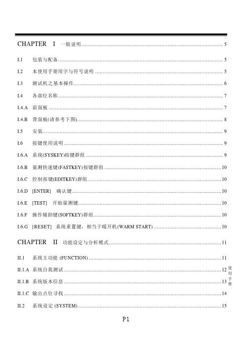
II.2.A.C LCD 亮度 ......................................................................................................... 16 II.2.A.D II.2.A.E II.2.A.F II.2.A.G LCD 反显 ...................................................................................................... 16 电源频率 ...................................................................................................... 16 开机自我测试................................................................................................ 17 系统语言 ...................................................................................................... 17
CHAPTER
II.1
II
功能设定与分析模式 ......................................................................... 11
系统主功能 (FUNCTION) ...................................................................................... 11
xl1509中文资料
xl1509中文资料Prediminarydatasheet 2A 150kHz 40V Buck DC DCconverter xl1509 Rev 2.0 Xinlong Semiconductor Limited Corporation宽输入电压范围4.5v-40v内置频率补偿,热关断功能,限流功能,短路保护功能可选包装形式:sop-8应用领域:通信/网络设备概述xl1509是一个150kHz固定频率脉冲宽度调制(降压)DC / DC转换器。
它具有2A负载驱动能力,高效率,低纹波和出色的线性度。
它具有良好的负载调节能力,并且只需要最少的外部组件。
可调输出,易于使用,内置频率补偿和固定频率振荡器。
PWM控制电路可将占空比从0调整到100%。
具有启用功能和内置的过电流和短路保护功能,在进行过电流和短路保护的情况下,xl1509的工作频率将从150kHz降低到50KHz。
内置频率补偿模块使xl1509的外部组件最大化。
图1xl1509封装类型的初步数据表2A 150kHz 40V Buck DC DC转换器xl1509 Rev 2.0新龙半导体有限公司xl1509的引脚结构(顶视图)表1引脚说明引脚编号引脚名称引脚名称VIN电压输入引脚xl1509在4.5V 40V 直流电压下工作,输入外部连接适用于大的接地旁路电容,以消除输入噪声。
SW电源开关输出引脚(SW)。
输出是提供功率输出的开关节点。
GND接地引脚必须精心设计。
该引脚必须放置在硝基基极二极管的外部,并且输出电容器接地,以防止由感应电压引起的开关电流毛刺输入到xl1509。
FB的反馈引脚(FB),通过外部电阻来分割环路,反馈是检测并调节输出电压,反馈端电压为1.23V。
开/关使能引脚。
如果驱动器的开/关引脚为低电平,则设备将被打开;否则,设备将被打开。
否则,设备将打开。
如果引脚为高电平,则设备将关闭。
初步数据表2A 150kHz 40V Buck DC转换器xl1509 Rev 2.0鑫隆半导体有限公司xl1509功能框图典型应用电路图4. Xl1509典型应用电路12v-5v / 2A初步数据表2A 150kHz 40V Buck DC DC转换器xl1509 Rev 2.0鑫隆半导体有限订购信息部件号标记标记标记温度范围封装类型xl1509-adje1 xl1509-adje1 3.3exl1509-3.3e1xl1509-3.3e1xl1509-3.3e1xl1509-3.3e1xl1509-3.3ee1xl1509-5.0e1xl1509-5.0e1xl 1509-5.01 e1xl1x1x1-3.3ttree1 xl1509-3.3tree1 xl1509-3.3tree1 xl1509-3.3tree1 xl1509-3.0 tree1 xl1509-5.0 tree1 xl1509-5.0 tree1 xl1509-5.0-5-5.0e1xl1509-5-5-5-5.0e1xl1509-5-5.0e1 xl1509-5-5-5.0e1 xl1509-5-5-5.0-exl1509-3.3e1e1xl1509-3.3e1 xl1509-3.3e1 xl1509-3.3e1 xl1509-5.3ee1xl1509-5.3e1-eee e5.3e40 xl13“E1”后缀符合ROHS标准初步数据表2A 150kHz 40V Buck DC DCconverter xl1509 Rev 2.0 Xinlong Semiconductor Limited Corporation maximum rati ng(注1)参数符号单位输入电压vin-0.3 fb-0.3开/关引脚电压开/关0.3输出-0.3内部极限MW(soic8)(结环境,未加热,自然通风)JA100 stg-的电阻焊接温度65引线(PIN)(热焊接,10引线260 ESD(人体模型)2000注1:超过所列的最大额定值将对设备造成永久性损坏。
XL4016原厂资料中文版演示-1

版 本:1.1 页 数:第 4 页, 共 6 页
DEMO 实物图
PCB 布局
50mm
65mm
顶层
底层
应用信息
输入电容选择 在连续模式中,转换器的输入电流是一组占空比约为 VOUT/VIN 的方波。为了防止大的瞬态电压,必须采用针对 最大 RMS 电流要求而选择低 ESR(等效串联电阻)输入电容器。对于大多数的应用,1 个 30uF 的输入电容器就足够了, 它的放置位置尽可能靠近 XL4016 的位置上。最大 RMS 电容器电流由下式给出:
第 1 页 ,共 6 页
XL4016原厂资料
XL4016 DEMO board manual
版 本:1.1 页 数:第 2 页, 共 6 页
物料清单
序号 1 2 3 4 5 6 7 8
数量 3 1 1 1 1 1 1 1
参考位号 C1, C2, CC
CI N COUT D1 L1 R1 R2 U1
I OUT( A) 0. 1 0. 5 1. 0 1. 5 2. 0 2. 5 3. 0 3. 5 4. 0 4. 5 5. 0 5. 5 6. 0 6. 5 7. 0 7. 5 8. 0
EFF( %) 84. 2 93. 0 93. 4 93. 2 92. 7 92. 3 91. 0 90. 6 89. 9 89. 4 89. 0 88. 4 87. 8 87. 2 86. 3 85. 6 85. 1
4.8
VIN=36V,VOUT=5V,IOUT=0.1A~8A
4.7 0.0 0.5 1.0 1.5 2.0 2.5 3.0 3.5 4.0 4.5 5.0 5.5 6.0 6.5 7.0 7.5 8.0
Output current(A)
ABB IRB 14050 夹具产品手册说明书

5 RAPID 参考
109
5.1 概述 ................................................................................................................ 109 5.2 指令: ............................................................................................................. 111
1 安全
11
1.1 安全信息简介 .................................................................................................... 11 1.2 一般安全风险 .................................................................................................... 12
8405中文资料

U E D P R O D U C T R E F E R E N C E O N L Y Designed specifically to meet the requirement for extended opera-tion of battery-powered equipment such as cordless and cellular tele-phones, the A8405SLH voltage regulators offer the reduced dropout voltage and quiescent current essential for maximum battery life.Applicable also to palmtop computers and personal data assistants,these devices deliver a regulated output at up to 200 mA (transient),which is internally limited, providing short-circuit protection. Regu-lated output voltages of 2.7, 2.8, 3.0, 3.2, 3.3, 3.6, 3.8, 4.0, and 5.0 V are currently provided. Other voltages, down to 2.0 volts, are available on special order.A PMOS pass element provides a typical dropout voltage of only 100 mV at 100 mA of load current. The low dropout voltage permits deeper battery discharge before output regulation is lost. Quiescent current does not increase significantly as the dropout voltage is ap-proached, an ideal feature in standby/resume power systems where data integrity is crucial. Regulator accuracy and excellent temperature characteristics are provided by a bandgap reference. The A8405SLH includes an ENABLE input to give the designer complete control over power up, standby, or power down.These devices are supplied in a thermally enhanced 5-lead small-outline plastic package similar to the SOT-23, and fitting the SC-74A footprint. All devices are rated for operation over a temperature range of -20°C to +85°C.FEATURES AND BENEFITSI High Efficiency Provides Extended Battery Life I 100 mV Typical Dropout Voltage at I O = 100 mA I 80 µA Typical Quiescent Current I Low Output NoiseI 200 mA Current-Limited OutputI Improved PSRR and Transient Performance APPLICATIONSI Cordless/Cellular/GSM/PHS Telephones I Personal Data Assistants I Personal Communicators I Palmtop Computers I GPS IPagersLOW-DROPOUT REGULATORS— HIGH EFFICIENCYData Sheet 27468.22PRELIMINARY INFORMATION(subject to change without notice)June 25, 1999Always order by complete part number, e.g., A8405SLH-xx , where “xx”is the required output voltage in tenths or “ADJ” for adjustable.84058405LOW-DROPOUTREGULATORS115 Northeast Cutoff, Box 15036Worcester, Massachusetts 01615-0036 (508) 853-5000Copyright © 1999, 2000 Allegro MicroSystems, Inc.A8405SLH Maximum Allowable Average Output Current* with device mounted on 2.24" x 2.24"(56.9 mm x 56.9 mm) solder-coated copper-clad board in still air.Allowable Total Average (10 ms) Output Current in Milliamperes with T J = 150°C, Duty Cycle = 100%†V I - V OT A 0.5 1.0 1.5 2.0 2.5 3.0 3.5 4.0* 4.5*25°C 20020020020020018916214212650°C 20020020020018215213011410170°C 200200200182145121104918185°C20020019714811898847466* Absolute maximum peak output current rating is 200 mA; absolute maximum input voltage is 7 V.† I O = (T J – T A )/([V I – V O ] R θJA x dc) = (150 – T A )/([V I – V O ] x 220 x 1.00)Output current rating can be increased (to 200 mA maximum) by additional heat sinking or reducing the duty cycle.8405LOW-DROPOUT REGULATORSELECTRICAL CHARACTERISTICS at T A = +25°C, V E ≥ 2.0 V, C BYPASS = TBD (unless otherwise noted).LimitsCharacteristicSymbol Test ConditionsMin.Typ.Max.Units Output VoltageV OV I ≥ V O(nom) + 1 V, 1 mA ≤ I O ≤ 150 mA*—±0.5—%(reference specified V O(nom))V I ≥ V O(nom) + 1 V, 1 mA ≤ I O ≤ 150 mA*,over operating temperature range ——±2.0%V I = V O(nom), I O = 50 mA——-0.25V Output Volt. Temp. Coeff.a VO V I = 6 V, I O = 10 mA, T J ≤ 125°C—TBD —mV/°C Output Short-Circuit Current I OM 200——mA Line Regulation ∆V O(∆VI)at V I = V O(nom) + 1 V, I O = 3 mA and V I = 7 V, I O = 3 mA— 1.0 2.0mV Load Regulation∆V O(∆IO)at V I = V O(nom) + 1 V, I O = 1 mAand V I = V O(nom) + 1 V , I O = 150 mA*— 2.0—mV at V I = 7 V, I O = 1 mAand V I = 7 V, I O = 150 mA*— 2.0—mV Dropout Voltage V I min - V OI O = 100 mA—100—mV Ground Terminal CurrentI GNDV I = V O(nom) + 1 V, I O = 1 mA —80100µA V I = V O(nom) + 1 V, I O = 150 mA*—80100µA V I = 7 V, I O = 1 mA —80100µA V I = 7 V, I O = 150 mA*—80100µA I QV I ≤ 7 V, V E ≤ 0.8 V, I O = 0 mA —— 1.0µA ENABLE Input VoltageV EH V I ≥ V O(nom) + 1 V, Output ON 2.0——V V ELV I ≥ V O(nom) + 1 V, Output OFF ——0.4V ENABLE Input Current I E V E = V I = 7 V——±1.0µA Internal Reference Voltage V REF — 1.26—V ADJUST Input Current I ADJ A8405SLH-ADJ only—0.10—µA Rejection Ratio PSRR V I = V O(nom) + 1.5 V, V i = 100 mV,I O = 30 mA, f = 60 Hz—70—dB Output Noise e n 10 Hz ≤ f ≤ 100 kHz, I O = 10 mA, C O = 10 µF —0.2—µV/√Hz Thermal ShutdownT J—170—°CTypical values are at T A = +25°C and are given for circuit design information only.* Pulse test (≤20 ms). See previous page for duty cycle limitations.8405LOW-DROPOUTREGULATORS115 Northeast Cutoff, Box 15036Worcester, Massachusetts 01615-0036 (508) 853-5000ENABLE(ACTIVE HIGH)INPUT (7.0 V MAX)APPLICATIONS INFORMATIONLinear regulators require input and output capacitors in order to maintain over-all loop stability. The recommended minimum value for the input capacitor is 0.1 µF. The output capacitor is the dominant pole that provides the high-frequency compensa-tion required for over-all regulator loop stability. These devices are stable with as little as 1 µF. However, to ensure stable operation under all conditions and capacitor types, the recom-mended minimum value is 4.7 µF. The output capacitor may be partially distributed through the load circuits. However, at least 1 µF should be connected at the regulator using the shortest and widest foil pattern possible.The A8405SLH-ADJ requires an external voltage divider to set up the desired regulated output voltage between 2.0 V and 6.8 V (V I ≤ 7 V). The two resistors are chosen such thatV O = 1.26 (R 1 + R 2)/R 2.The resistor values are usually as high as possible to maintain high circuit efficiency, but R 2 should be less than 300 k Ω.Thermal ConsiderationsThese devices are intended to provide more than 150 mA of continuous current in a very small package. The table on page 2of this data sheet gives the maximum allowable average output current for a worst-case printed circuit design (R θJA = 220°C/W with a minimum footprint). Performance improvement is easily accomplished with the addition of 1 square inch of copper at terminal 2 (R θJA = 170°C/W).8405LOW-DROPOUT REGULATORSDimensions in Inches(for reference only)Dimensions in Millimeters(controlling dimensions)MINDwg. MA-011-5 mmNOTES: 1. Tolerances on package height and width represent allowable mold offsets.Dimensions given are measured at the widest point (parting line).2. Exact body and lead configuration at vendor’s option within limits shown.3. Height does not include mold gate flash.4. Where no tolerance is specified, dimension is nominal.MIN8405LOW-DROPOUTREGULATORS115 Northeast Cutoff, Box 15036Worcester, Massachusetts 01615-0036 (508) 853-5000This page intentionally left blank8405LOW-DROPOUTREGULATORSThis page intentionally left blank8405LOW-DROPOUTREGULATORS115 Northeast Cutoff, Box 15036Worcester, Massachusetts 01615-0036 (508) 853-5000Allegro MicroSystems, Inc. reserves the right to make, from time to time, such departures from the detail specifications as may be required to permit improvements in the design of its products.The information included herein is believed to be accurate and reliable. However, Allegro MicroSystems, Inc. assumes no responsibility for its use; nor for any infringements of patents or other rights of third parties which may result from its use.。
1956551资料
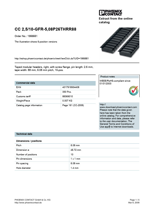
Extract from the onlinecatalogCC 2,5/10-GFR-5,08P26THRR88Order No.: 1956551The illustration shows 6-position versionshttp://eshop.phoenixcontact.de/phoenix/treeViewClick.do?UID=1956551Taped modular headers, right, with screw flange, pin length: 2.6 mm, tape width: 88 mm, 5.08 mm pitch, 10-pos.http://Please note that the data givenhere has been taken from theonline catalog. For comprehensiveinformation and data, please referto the user documentation. TheGeneral Terms and Conditions ofUse apply to Internet downloads. Technical dataDimensions / positionsPitch 5.08 mmDimension a45.72 mmNumber of positions10Pin dimensions 1 x 1 mmPin spacing 5.08 mmHole diameter 1.4 mmTechnical dataInsulating material group IIIaRated surge voltage (III/3) 4 kVRated surge voltage (III/2) 4 kVRated surge voltage (II/2) 4 kVRated voltage (III/2)320 VRated voltage (II/2)400 VConnection in acc. with standard EN-VDENominal current I N12 ANominal voltage U N250 VMaximum load current12 A (per position)Insulating material LCPInflammability class acc. to UL 94V0Certificates / ApprovalsApproval logoCULNominal voltage U N300 VNominal current I N10 AULNominal voltage U N300 VNominal current I N10 ACertification CUL, ULAccessoriesItem Designation DescriptionGeneral1954362CR-MSTB NAT HT HT coding section, is pushed into the recess on the header beforethe reflow process, made of highly temperature-resistant, beigeinsulating materialMarking1051993B-STIFT Marker pen, for manual labeling of unprinted Zack strips, smear-proof and waterproof, line thickness 0.5 mm0804293SK 5,08/3,8:FORTL.ZAHLEN Marker card, printed horizontally, self-adhesive, 12 identicaldecades marked 1-10, 11-20 etc. up to 91-(99)100, sufficient for120 terminal blocks0805085SK 5,08/3,8:SO Marker card, special printing, self-adhesive, labeled acc. tocustomer requirements, 12 identical marker strips per card, max.25-position labeling per strip, color: white0805412SK 5,08/3,8:UNBEDRUCKT Marker cards, unprinted, with pitch divisions, self-adhesive, 10-section marker strips, 12 strips per card, can be labeled with theM-PENPlug/Adapter1734401CR-MSTB Coding section, inserted into the recess in the header or theinverted plug, red insulating materialDrawingsApplication drawingDrilling diagramDimensioned drawingBottom view, free space for solder paste, 0.5mm deepDirection of the arrow = feeding directionAddressPHOENIX CONTACT GmbH & Co. KGFlachsmarktstr. 832825 Blomberg,GermanyPhone +49 5235 3 00Fax +49 5235 3 41200http://www.phoenixcontact.de© 2008 Phoenix ContactTechnical modifications reserved;。
XL7035 datasheet-Chinese
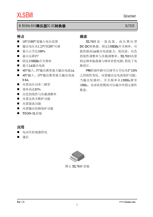
1A 150KHz 80V 降压型DC-DC 转换器 XL7035特点10V到80V 宽输入电压范围 输出电压从1.25V 到20V 可调 最大占空比100% 最小压降1V固定150KHz 开关频率 最大1A 输出电流48V 输入、5V 输出推荐最大输出电流1A 48V 输入、15V 输出推荐最大输出电流0.6A内置高压功率三极管 效率高达85%出色的线性与负载调整率 内置过热关断护功能 内置限流功能 内置输出短路保护功能 TO263-5L 封装应用电动车控制器供电 通信描述XL7035是一款高效、高压降压型DC-DC 转换器,固定150KHz 开关频率,可提供最高1A 输出电流能力,低纹波,出色的线性调整率与负载调整率。
XL7035内置固定频率振荡器与频率补偿电路,简化了电路设计。
PWM控制环路可以调节占空比从0~100%之间线性变化。
内置输出过电流保护功能,当输出短路时,开关频率从150KHz降至45KHz。
内部补偿模块可以减少外围元器件数量。
图1. XL7035封装1A 150KHz 80V降压型DC-DC转换器XL7035引脚配置1A 150KHz 80V降压型DC-DC转换器XL7035用于限制最大输出电流,当豪欧姆;当时,R3选择1A 150KHz 80V降压型DC-DC转换器XL70351A 150KHz 80V降压型DC-DC转换器XL70351A 150KHz 80V降压型DC-DC转换器XL70351A 150KHz 80V降压型DC-DC转换器XL70357. XL703520V~80V, 15V/0.6A)951A 150KHz 80V降压型DC-DC转换器XL7035图9. XL7035(VIN=10V~80V, VOUT=5V/1A)901A 150KHz 80V降压型DC-DC转换器XL70351A 150KHz 80V降压型DC-DC转换器XL7035重要申明XLSEMI保留在任何时间、在没有任何通报的前提下,对所提供的产品和服务进行更正、修改、增强的权利。
N50P111;中文规格书,Datasheet资料

DatasheetEasyPoint TMN50P111Navigation Module1 General DescriptionEasyPoint™ N50P111 is a miniature joystick module concept based on contact-less, magnetic movement detection. The integrated two-dimensional linear encoder monitors the movement of the magnet incorporated in the knob and provides directly the x and ycoordinates via I²C output. An integrated mechanical push button built in the module provides a “select” function.Figure 1. N50P111-xxxxx-H2 Key FeaturesXY coordinates direct read with 8-bit resolution 2.7V to 3.6V operating voltage Down to 1.7V I/O voltageLateral magnet movement radius up to 2.0mm High-speed I²C interfaceConfigurable interrupt output for motion detection Push button feature3 ApplicationsThe EasyPoint™ N50P111 is ideal for small form-factor manual input devices in battery operated equipment, such as Mobile phones, MP3 players, PDAs, GPS receivers, Gaming consoles and Analog joystick replacement.4 BenefitsHigh reliability due to magnetic non-contact sensing Low power consumption Two operating modes-Idle mode-Low Power modeN50P111Push button GNDI²C AddressGND: 0x40VDDp: 0x41AS5013Two-dimensional magnetic encoderContents1 General Description (1)2 Key Features (1)3 Applications (1)4 Benefits (1)5 Pin Assignments (4)5.1 Pin Descriptions (4)6 Absolute Maximum Ratings (5)7 Electrical Characteristics (6)7.1 Operating Conditions (6)7.2 Digital IO Pads DC/AC Characteristics (6)7.3 Switch Characteristics (7)7.4 Mechanical Specifications (8)7.5 Recommended Reflow Temperature Profile (8)8 Using the N50P111 Module (9)8.1 Powering up the Module (9)8.2 Registers Initialization (9)8.3 C Source Code Example (10)8.3.1 Initialization (10)8.3.2 Offset Calibration (10)8.3.3 Dead Zone area (11)8.3.4 Interrupt Routine (11)9 XY Coordinates Interpretation (12)9.1 EasyPoint Operating Principle (12)9.1.1 Knob Displacement and Register Value Relation (13)9.2 Operation Principle (14)10 I²C interface (15)10.1 Interface Operation (15)10.2 I²C Electrical Specification (16)10.3 I²C Timing (17)10.4 I²C Modes (18)10.4.1 Automatic Increment of Address Pointer (18)10.4.2 Invalid Addresses (18)10.4.3 Reading (18)10.4.4 Writing (18)10.4.5 High Speed Mode (21)10.4.6 Automatic Increment of Address Pointer (22)10.4.7 Invalid Addresses (22)10.5 SDA, SCL Input Filters (22)11 I²C Registers (23)11.1 Control Register 1 (0Fh) (23)11.2 X Register (10h) (25)11.3 Y_res_int Register (11h) (25)11.4 Xp Register (12h) (25)11.5 Xn Register (13h) (25)11.6 Yp Register (14h) (26)11.7 Yn Register (15h) (26)11.8 M_ctrl Register (2Bh) (26)11.9 J_ctrl Register (2Ch) (27)11.10 T_ctrl Register (2Dh) (27)11.11 Control Register 2 (2Eh) (27)11.12 Registers Table (28)12 Package Drawings and Markings (30)Datasheet - P i n A s s i g n m e n t s5 Pin Assignments5.1 Pin DescriptionsTable 1. Pin DescriptionsConnector Pin #Pin Type Description 1Power VDDp: IO power supply for SCL, SDA, INTn, 1.7V ~ 3.6V2Power VDD: Core power supply, 2.7V ~ 3.6V3Power GND4Bi-directional SDA: I²C bus data, open drain5Input SCL: I²C bus clock6Input RESETn: Reset input, active LOW0: GND → Reset, all registers return to their reset value 1: VDDp → Normal operation mode7Open drain INTn: Interrupt output, open drain: Active: LOWInactive: Hi-Z8Output SWITCHn: Push button signal output: Not pushed: OpenPushed: GND9Input ADDR: I²C Address selection input:0: GND → 0x401: VDDp → 0x411234J1VDDVDDpSCLSDAGNDDatasheet - A b s o lu t e M a x im u m R a ti n g s6 Absolute Maximum RatingsStresses beyond those listed in Table 2 may cause permanent damage to the device. These are stress ratings only, and functional operation of the device at these or any other conditions beyond those indicated in Electrical Characteristics on page 6 is not implied. Exposure to absolute maximum rating conditions for extended periods may affect device reliability.Table 2. Absolute Maximum RatingsSymbol Parameter Min Max Units NotesV DD DC supply voltage-0.35VVDDp Peripheral supply voltage-0.35VDD + 0.3V SCL, SDA, RESETn, ADDRV IN Input pin voltage -0.3VDDp + 0.3VSCL, SDA, RESETn, ADDR - 3.6VI SCR Input current (latchup immunity)-100100mA Norm: JEDEC 78ESD Electrostatic discharge-±2kV All pins, Norm: MIL 883 E method 3015 T Strg Storage temperature-4085ºCHumidity non-condensing585%Degrees of protection IP5X Norm: IEC 605297 Electrical Characteristics7.1 Operating ConditionsT AMB = -20 to +70ºC, VDD = 3.3V 7.2 Digital IO Pads DC/AC CharacteristicsTable 3. Operating Conditions Symbol ParameterMin TypMax Units NotesVDDCore Supply voltage2.73.6VVDDp Peripheral Supply voltage 1.7VDD VInput: RESETnOpen drain outputs: SCL, SDA, INTn.External I²C pull up resistor to be connected to VDDp.IDD SMaximal average current consumption on VDD,Pulsed peaks = IDD fdepends on the sampling time ts[ms]3+3760/ts [ms]µAT AMB = -20 to +50 ºC10+3760/ts [ms]T AMB = 50 to +70 ºC IDD I Current consumption on core supply, Idle mode,no readout (ts = infinite)3µAT AMB = -20 to +50 ºC10T AMB = 50 to +70 ºC IDD f Current consumption on core supply,Full Power mode 10mA Continuous current pin VDD Maximum sampling ts = 450µs Tpua Power up time analog 1000µs Step on VDD to Data_Ready Tconv Conversion time 450µs Read X/Y coordinate I²C STOP condition to Data_Readyt P,W Nominal wakeup time 20320ms T AMBAmbient temperature range -20+70ºCResolution of XY displacement8Over 2*dx and 2*dy axisTable 4. Digital IO Pads DC/AC Characteristics Symbol ParameterMinMaxUnitsNotesInputs: SCL, SDAV IH High level input voltage 0.7 * VDDpV I²C V IL Low level input voltage 0.3 * VDDpV I²C I LEAK Input leakage current 1µA VDDp = 3.6V Inputs: ADDR, RESETn (JEDEC76)V IH High level input voltage 0.65 * VDDpV JEDEC V IL Low level input voltage 0.35 * VDDpV JEDEC I LEAK Input leakage current1µAVDDp = 3.6VOutputs: SDAV OHHigh level output voltageOpen drainLeakage current 1µA High level outputvoltage7.3 Switch CharacteristicsV OL1Low level output voltageVSS + 0.4V-6mA; VDDP > 2V;fast mode V OL3VDDP * 0.2V-6mA; VDDP ≤ 2V;fast mode V OL1VSS + 0.4V-3mA; VDDP > 2V;high speed V OL3VDDP * 0.2V -3mA; VDDP ≤ 2V;high speed C L Capacitive load 400pF standard mode ( 100 kHz )400pF fast mode ( 400 kHz )100pFhigh speed mode ( 3.4 MHz )Outputs: INTn (JEDEC76)V OH High level output voltage Open drain1µA Leakage current High level output voltageV OL Low level output voltageVSS + 0.2V -100µA VSS + 0.45-2mA C LCapacitive load30pFstandard mode ( 100 kHz )Table 5. Switch CharacteristicsParameterMinMax Units Notes Contact resistance of dome switch 750m ΩNorm: EIA-364-23Dielectric withstanding voltage100Vac Norm: EIA-364-20Insulation resistance 100m ΩNorm: EIA-364-21, 100VdcBouncing (On/Off)5msRate: 2 times/sec.Table 4. Digital IO Pads DC/AC Characteristics Symbol ParameterMinMax Units Notes7.4 Mechanical Specifications7.5 Recommended Reflow Temperature ProfileTable 6. Mechanical SpecificationsParameter Note Number of operating shaftsSingle shaft Shaft material LCP Housing material LCP & PA46Shell material Stainless Steel or Copper alloyTravel (XY operation)±2.00mm (±10%)Travel (Z push operation)0.22mm (±0.05mm)Directional operating force (XY direction)0.70N (±0.15N)Push operating force (Z direction)1.80N (±15%)Vibration10-500-10Hz 15 minutes, 12 cycles, 3 axes (total 36 cycles)Operating life – XY direction Each direction > 1 million cyclesOperating life – Push Z direction > 1 million cyclesShaft strength (XYZ direction)> 3.5 kgfFree fall Dispensing Glue40 drops(2X6 sides + 1X12 edges + 2X8 corners) @ 1.5m drop height to concrete surface, module is assembled to phone mechanics.Over forceDispensing Glue 1.5kgf > 100k cycles8 Using the N50P111 Module8.1 Powering up the ModuleThe N50P111 module has a Power ON Reset (POR) cell to monitor the VDD voltage at startup and reset all the internal registers. After the internal reset is completed, the POR cell is disabled in order to save current during normal operation.If VDD drops below 2.7V down to 0.2V, the POR cell will not be enabled back, and the registers will not be correctly reseted or can get random values.Note:It is highly recommended to control the external RESETn signal by applying a LOW pulse of >100ns once VDD has reached 2.7V and VDDp reached 1.7V.8.2 Registers InitializationAfter Power Up, the following sequence must be performed:1. VDD and VDDp Power up, and reached their nominal values (VDD>2.7V, VDDp>1.7V).2. Initialization:a. RESETn pulse LOW during >100ns, then RESETn HIGHb. Loop check register [0Fh] until the value F0h or F1h is present (reset finished, registers to default values)c. Write value 16h into register [2Dh]3. Perform an Offset Calibration (X and Y coordinate compensation for zero position)4. Configure the Dead Zone Area for Wake-up function (if needed)5. Configure the wanted Power Mode and INT function into register [0Fh] (Idle mode / Low Power Mode with Timebase configuration, INTfor Wake-up or Coordinates ready)6. X Y coordinates are ready to be read.8.3 C Source Code Example8.3.1 Initializationvoid EasyPoint_init (void){unsigned char Reset_status = 0;RESETn = 0;Delay_ms(1);// RESETn pulse after power upRESETn = 1; Delay_ms(1);while (Reset_status != 0xF0)// Check the reset has been done{Reset_status = I2C_Read8(0x40, 0x0F) & 0xFE;}I2C_Write8(0x40, 0x2E, 0x16); // Scaling factor for N50 (2.0mm knob travel) }8.3.2 Offset Calibrationvoid Offset_Calibrate (void){char i;int x_cal=0, y_cal=0;EA = 0;// Disable the MCU interruptsI2C_Write8(0x40, 0x0F, 0x00);// Low Power Mode 20msDelay_ms(1);I2C_Read8(0x40, 0x11); // Flush an unused Y_reg to reset the interruptfor (i=0; i<16; i++)// Read 16 times the coordinates and then average{while (INTn);// Wait until next interrupt (new coordinates)x_cal += (signed char) I2C_Read8(0x40, 0x10); // Read X positiony_cal += (signed char) I2C_Read8(0x40, 0x11); // Read Y position }// offset_X and offset_Y are global variables, used for each coordinate readout in the interrupt routineoffset_X = -(x_cal>>4); // Average X: divide by 16offset_Y = -(y_cal>>4); // Average Y: divide by 16EA = 1; // Enable the MCU interrupts}分销商库存信息: AMSN50P111。
xl4015中文资料_数据手册_参数

Pin Number 1
2 3 4 5
Pin Name GND
FB SW VC VIN
Description
Ground Pin. Care must be taken in layout. This pin should be placed outside of the Schottky Diode to output capacitor ground path to prevent switching current spikes from inducing voltage noise into XL4015. Feedback Pin (FB). Through an external resistor divider network, FB senses the output voltage and regulates it. The feedback threshold voltage is 1.25V. Power Switch Output Pin (SW). SW is the switch node that supplies power to the output. Internal Voltage Regulator Bypass Capacity. In typical system application, The VC pin connect a 1uf capacity to VIN. Supply Voltage Input Pin. XL4015 operates from a 8V to 36V DC voltage. Bypass Vin to GND with a suitably large capacitor to eliminate noise on the input.
A50-645-4520中文资料

Assembly Instruction BBAI-1231 (Apply ITT Cannon Sales Dept.) Right Angle Crimp Plug Screw Coupling
Straight Bulkhead Crimp Jack All Couplings
Part Number F50-A27-3002A90 F50-A27-3003A90 F50-A27-3033A90 F50-A27-3035A90 Assembly Instructions F50-A27-3002A90 F50-A27-3003A90 F50-A27-3033A90 F50-A27-3035A90 Cable Numbers 2YCCY 0.4/2.5 2YCY 0.7/4.4 BT2003 BT3002, TZC75024
* Guideline value only– will depend on cable and connector type
1.6/5
Dimensions are shown in mm (inch) Dimensions subject to change
59
元器件交易网
1.6 / 5.6
MECHANICAL Withdrawal force inner female contact Withdrawal force inner male contact Insertion force between jacks and plugs Withdrawal force between jacks and plugs Materials
FR-A540中文使用手册

A-3
注意
●电子过电流保护不能完全确保对电机的过热保护。 ●不要频繁使用变频器输入侧的电磁接触器启/停变频器。 ●用噪声滤波器减少电磁干扰的影响。否则有可能影响变频器附近使用的电子设备。 ●采取相应的措施抑制谐波。否则由于变频器产生的电源谐波,使电力电容和发电设备过热及损坏。 ●当变频器驱动 400V系列电机时,必须增强电机绝缘或抑制浪涌电压。由于布线常数引起的浪涌电压发 生于电机的端子,使电机的绝缘恶化。 ●当进行参数清除或参数全部清除时,各参数返回到出厂设定值,在运行前请再次设定必要的参数。 ●变频器可以容易地进行高速运行的设定,更改设定前,检查电机和机械性能有充分的能力。 ●请增加变频器的保持功能,安装保持设备以确保安全。 ●变频器长时间保存后再使用,使用前必须进行检查和试运行。
目 录
2 安装和接线
7
2.1 安装............................................................................................. 7 2.1.1 安装说明 ..................................................................................... 7 2.2 接线............................................................................................. 9 2.2.1 端子接线图 ................................................................................... 9 2.2.2 主回路接线 .................................................................................. 12 2.2.3 控制回路接线 ................................................................................ 17 2.2.4 与PU接口的连接 .............................................................................. 20 2.2.5 连接独立选件单元 ............................................................................ 23 2.2.6 设计说明 .................................................................................... 27 2.3 其他接线 ........................................................................................ 28 2.3.1 电源谐波 .................................................................................... 28 2.3.2 变频器噪音的产生和减少方法 .................................................................. 29 2.3.3 漏电流及其对策 .............................................................................. 31 2.3.4 变频器驱动 400V 级电机 ...................................................................... 32 2.3.5 周围设备 .................................................................................... 33 2.3.6 有关UL, cUL的注意事项 ................................................................ 35 2.3.7 符合欧洲标准的说明 .................................................................. 36
XL50说明书

空调自控系统说明书苏州达实控制设备有限公司2011.12 一:控制器说明:XCEL50控制器是Honeywell(霍尼韦尔)XBS 楼宇自动化系统中的现场DDC控制单元,是替代EXCEL20控制器的最新产品,可应用与于单独的AHU就地控制,它内含通讯模块可与EXCEL 5000系统集成在一个网路中,同时提供ISDN和LON总线的通信方式,EXCEL50控制器采用Flash EPROM模块可自由编程适用于Honeywell的CARE编程软件包,控制器可根据需要提供不同的现场预制程序。
1)硬件部分硬件结构8路通用传感器输入----- Analog input4 路无源数字量输入-----Digital input6 路数字点输出 -----Digital outputt4 路模拟点输出 ----- Analog outputI/O点特性:通用输入: NTC热敏电阻、PT1000温度传感器、0~10VDC信号、4~20mA 信号、干接点;数字输入:无源干接点、逻辑电平、记数脉冲;通用输出:模拟输出0~10VDC;数字输出:TRAIC输出;2):技术规范工作电压 24VAC工作频率 50/60HZ输入分辨率 0.1K/1MA电压调节信号 0~10V查询速度和刷新时间 1s继电器触点电压 24~220VAC触点最大负载 4A二:控制原理:1):温度控制在使用时根据实际,选择冷热模式.夏季,由回风温度控制冷水阀,即当回风温度高于除湿设定值时开大冷水阀,冷水流量增加,制冷能力增加,当回风温度低于设定值时关小冷水阀,冷水流量减少, 制冷能力减少。
在冬季,由回风温度控制热水阀,即当回风温度低于加热设定值时打开热水阀.2):室内静压控制根据室内的静压控制新风阀和回风阀的开度.3):联锁控制1.空调系统与风机联锁, 当风机启动时, 控制系统正式启动,各个控制元件开始控制过程;2.风机与冷热水阀、电加热器、加湿器的联锁控制,当送风机停机时,相应设备全部关闭三:操作说明:1、基础操作键:“取消键”,退出上级菜单或取消已修改的参数或退出报警确认;“上行键”,移动光标至上一行;“下行键”,移动光标至下一行;“右行键”,移动光标至下一个参数栏;“左行键”,移动光标至上一个参数栏;“增加键”,增加一个修改的单位或切换数字量的一个状态;“减少键”,减少一个修改的单位或切换数字量的一个状态;“确认键”,确认已修改的参数或移动光标至下一个界面2、功能操作键:“PLANT键”,显示该现场DDC控制器的相关状态;“TIME 键”,显示该现场DDC控制器的时间控制程序;如:控制器当前时间、TIMESCHEDUL时间表等,该功能在本系统未使用“参数键”,显示该现场DDC控制器的所有数据、控制点的状态、设定点、DDC参数表等;“报警键”,显示该现场DDC控制器的所有报警状态、报警历史、已处于ALARM的数据点;3、高级操作:3.1通电后,按,出现如下菜单3.2按菜单键,首先进入密码菜单后,先按键,进入以下菜单:进入密码3333,按键进入以下菜单按键可选择进入相应选项,按键确认。
40PC015V2A中文资料

40PC015V2A中文资料Order Product and Get SupportU.S. Authorized DistributorsGlobal Sales & Service N. American Sales Reps Distributor Inventory Technical Assistance White P apers Literature Request Test and Measurement CatalogRoHS P roduct List Customer FeedbackHome> Products > Piezoresistive Silicon > 40PC > P roduct P age40PC015V2APressure Sensors: MeasurementType: Vacuum; Amplified; Range: 0 psito -15.0 psiActual product appearance may vary.Featuresl Smallest amplified sensor packagel Minimal P CB spacel Fully signal conditionedl Operating temperature range from -45 °C to 125 °C [-49 °F to 257 °F]l Silicon piezoresistive technologyl Monolithic designl 6 P in DIP packagel Port designed for O-ring interfacePotential ApplicationsMedicall Oxygen and nitrogen gas distribution inhospitalsl Dental chairsl CPAP (Continuous P ositive Airw ay Pressure) equipmentl Respirators and ventilatorsl Blood glucose monitorsl Oxygen conserversl Oxygen concentratorsl Nebulizersl Kidney dialysis machinesl Blood cell separatorsl Hospital bedsEnvironmentall Water control valvesl Instrumentationl Irrigation equipmentl Filter monitoring equipment Industrial Instrumentationl Roboticsl Pressure valvesl Leak detectionl Air compressorsAnalytical Instrumentationl Gas chromatographyl Chemical Analyzers Transportationl Electronic brake systemsl Engine oil levell Transmission fluid levell Air conditioning systeml Fuel injection systems DescriptionThe cost-effective 40PC Series miniature pressure sensor is the smallest amplifiedpressure sensor manufactured by Honeyw ell. The fully calibrated and temperature-compensated sensor is very robust, covering a w ide range of temperatureextremes. Additionally, the 40PC Series is compatible w ith a broad array of media,from dry air and w ater to refrigerant coolants and engine fuel. The 0.5 Vdc to 4.5Vdc analog output voltage signal is linearly proportional to input pressure. Thesedevices operate on a single end supply voltage of 5.0 Vdc.Supporting DocumentationNone AvailableProduct SpecificationsMeasurem ent Type Vacuum GageSignal Conditioning Am plifiedPressure Range0 psi to -15.0 psiMaxim um Overpressure30.0 psiSup ply Voltage 5.0 Vdc ±0.25 VdcCom pensated YesOutput Calibration YesResponse Tim e 1 m s m ax.Term ination PCB; Leads form ed away from portPort Style Straight for O-ring interfacePackage Style Honeywell - MonolithicLinearity0.30% span m ax.Typical Sensitivity266.6 m V/psiFull Scale Span 4.0 Vdc typ.Null Offset0.50 Vdc typ.Null Shift over Tem perature±2.00 m ax.Span Shift Over Tem perature±3.50 m ax.Repeatability & Hysteresis Error±0.15 % span typ.Shock Qualification tested to 150 gVibration MIL-STD-202 Method 213 (150 ghalf sine 11 m s)Operating Tem perature Range-45 °C to 125 °C [-49 °F to 257 °F]Com pensated Tem perature Range-45 °C to 85 °C [-49 °F to 185 °F]Storage Tem perature Range-55 °C to 125 °C [-67 °F to 257 °F]Media Com patibility Port 1: Dry gases only. Mediam ust be com patible with epoxy-based adhesive. Port 2: Wettedm aterials. Media m ust becom patible with glass, silicon,stainless steel, invar, Sn/Ni platingand Sn/Ag solder.UNSPSC Code411121UNSPSC Com m odity411121 TransducersAvailability GlobalSeries Nam e40PCMy LinksLogin to iCOMLogin as Rep/ADLogin as GuestLogin to DigitalUniversityKeyw ord SearchSearch for product andsupport information.All Sensing and ControlProduct SearchPart number search:Use (*) to expand searchSpecification SearchTerms & Conditions | Privacy Statement | Site Map 元器件交易网/doc/2316046389.html,。
SMH-50 50 50-150-XL 硬體操作說明書说明书

SMH-50/50/50-150-XL 硬体操作说明书匯出日期:2023-10-19修改日期:2021-04-19•••••••••••••••••••••••目录序言适用机型硬体规格说明外观介绍外形尺寸驱动器规格搬运与安装搬运安装环境条件与注意事项配线与信号周边装置接线图驱动器的连接器与端子说明各式配线图串列向量配线图新代编码器外接类比温感配线图多台四合一串联说明回生电阻选用简易回生电阻选择详细回生电阻选择KTY84温感器与过温度保护功能安装驱动器参数设定版本号编修日期编修内容作者审查核准V1.22022-6-30修正为SMD-34B-50150-xx 硬体操作说明书带电池盒乃维V1.12020-7-23刪去電容吸收能量Ec黃揚程V1.02018/10/04新增SMD-34B-50150-xx 硬体操作说明书杨娟HomePageSYNTEC伺服操作说明书文件资讯文件履历文件资讯文件履历1 序言感谢您长期对本公司产品的使用与支持。
本公司伺服团队不断致力於各项产品的研发,期许本公司产品与服务能给使用者带来最大的效益。
新代高性能驱动器系列产品为本公司最新推出之伺服驱动器,本产品使用高品质之元件与材料,并经过严格测试,采用精密向量控制,具有高精确度、高稳定性、高效率之特性。
本使用说明内容包括驱动器的硬体规格、安装、配线与讯号,能提供给使用者最正确的指引与操作,为充分发挥产品应有的优异性能与维护人员及设备的安全,在使用前请详细阅读本使用手册,并且妥善保存,以备日後调校与保养时使用,若有任何疑虑,请与本公司联络,本公司专业人员将竭诚为您服务。
2 适用机型本操作手册适用於新代 3KWX3+18.5KW四合一驱动器3 硬体规格3.1 说明每部驱动器在出厂前均经过详细品管检查与防撞包装处理,请使用者收到产品後应先检查外观有无撞击损伤,并将外盒与产品上之序号做比对是否一致,若有不符,请第一时间与本公司联络。
型号说明3.2 外观介绍SMH-50/50/50-150-XL驱动器功能模块说明A外供电源输入接点连接380V~440V三相交流电(RST) B马达驱动电源输出接点连接马达侧提供马达电源(UVW)由右至左分别为第一至第四轴C煞车电阻接点煞车电阻接点(P-B)D MIII串行通讯接孔连接上位控制器(MIII讯号)连接串行驱动器 (MIII讯号) E Mini USB接孔连接个人计算机调机使用F I/O讯号端口外接电池端口连接I/O设备(急停、警示灯…等)连接绝对型编码器供电电池G STO讯号端口STO接口,2组安全输入,1组安全功能回授H编码器回授接孔由上至下分别为第一至第四埠。
Honeywell-XL50控制器操作说明
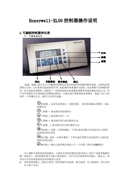
Honeywell-XL50控制器操作说明1.可编程控制器和仪表可编程控制器XL20、XL50 (的核心元件,它在系统中起到重要作用:如检测各传感器的当前值,动态调整个比例阀的状态,显示系统各参数等;还提供了一些控制系统内部参数的调整和系统参数的设定方式,用户应对其操作方法和性能达到熟练的程度,才能实现空调系统的各种操作。
XL20为中文控制屏,不带通讯方式,操作方法雷同XL50。
取消键–返回先前的或上一级的屏幕;取消未被确认的操作;确认报警信息。
上移键–移动指针到前面的行下移键–移动指针到下一行右移键–移动指针到当前位置的右边左移键–移动指针到当前位置的左边增加键–每按一次增加数值一个单位或改变数字状态值到与当前状态值相反的状态值减少键–每按一次减少数值一个单位或改变数字状态值到与当前状态值相反的状态值确认键–确认已做的修改和进入下一个屏幕(指针在NEXT前)对于KTF空调系统的控制操作,主要是对系统参数的查看和更改(即对“系统参数操作键”的使用),该控制器的强大功能主要体现在:不但可以在线修改所有输入、输出点,而且也可以对控制系统的内部参数进行改变。
a)查看系统的输入、输出点状态(即查询新回风温度、露点温度、出口温湿度、风压及其各个阀门开度)♦ 重要说明:对DDC 控制器的操作只能单键进行,严禁同时按压键位,以避免不必要的误操作,以免程序被初始化或删除。
♦ 按下系统“参数”操作键,屏幕出现“请输入你的密码”;密码输入才可以修改数据,比如压力等参数的设定等。
用户只是查看的话就可以直接进入。
♦ 移动“光标移动”向上键,使光标停留在“****”上,再按下“输入键”,通过使用“数据增/减键”和“输入键”逐个将4位密码输入,完毕后屏幕左下角出现‘更改change ’字符;光标移动到change 字符上可以修改进入DDC 修改数据的密码,默认为‘3333’,如更改了密码,用户须牢记更改后的密码,每次参数修改操作都需密码。
- 1、下载文档前请自行甄别文档内容的完整性,平台不提供额外的编辑、内容补充、找答案等附加服务。
- 2、"仅部分预览"的文档,不可在线预览部分如存在完整性等问题,可反馈申请退款(可完整预览的文档不适用该条件!)。
- 3、如文档侵犯您的权益,请联系客服反馈,我们会尽快为您处理(人工客服工作时间:9:00-18:30)。
International Safety Standard Approvals
VDE0805/EN60950/IEC950 File No. 10401-3336-1003 Licence No. 1230 UL1950 File No. E136005
CSA C22.2 No. 950 File No. LR41062C/LR50913C/LR101320
XL50-4601 Certificate No. 601004, XL50-4602 Certificate No. 601003, XL50-4603 Certificate No. 601002
[ 2 YEAR WARRANTY ]
• UL, CSA, VDE and BABT approved • 115/230VAC input selectable • Input surge current protection
• Overvoltage protection on +5V output • Fast transient response
These low power multi-output switchers offer 60 Watts of output power in a compact open frame package. The XL50 are quad output units, which can deliver 60 Watts. The four models in this series provide output voltage
combinations of +5V , –5V , +12V , –12V , +15V , –15V and +24V . VDE/FCC level B conducted EMI compliance are standard as is VDE, UL, CSA and BABT approvals. These low power units are ideal for small computer applications.Designed for microprocessor and VDU applications, with memory, disk drives,printers and other I/O devices.
SPECIFICATION
All specifications are typical at nominal input, full load at 25°C unless otherwise stated
PAGE 1
60W
30W
MINIMUM LOAD REQUIRED FOR NORMAL OPERATION
SEE NOTE 3
0°C 10°
C 20°C 30°C 40°C 50°C 60
°C 70°C
DERATING CURVE
Output Power (Watts)
0W
Notes
1Peak current in excess of the maximum indicated rating may be available on some outputs. However, this will affect output regulation. Consult factory for details.2
For stated regulation:* 0.4≤I 1/I 2≤6 and I 1+I 2≤8A
where I 1is V1 output current and I 2is V2 output current.
Regulation in the output voltage and current table is defined as the static output regulation at 25°C, including initial tolerance, line voltage within stated limits, and output voltages adjusted to their factory settings.3
The following minimum loads are required to ensure operation within specified regulation limits:
XL50-4601: 5V/1A, +12V/500mA XL50-4602: 5V/1A, +24V/400mA
XL50-4603: 5V/1A, +12V/500mA +12V/1A XL50-4604: 5V/1A, +15V/500mA
4Three orthogonal axes, sweep at 1 octave per minute. 30 minute dwell at each major resonance.5Fuse is rated at 2A/250V .
6
This product is only for inclusion by professional installers within other equipment and must not be operated as a stand alone product.
AC mating connector
Molex 09-92-0500 or equivalent with 2478 series crimp terminal or equivalent.
DC mating connector
Molex 09-92-1300 or equivalent with 2478 series crimp terminal or equivalent.
PAGE 2。
