LDEID2820中文资料
IC-2820H中文说明书
2 / 42
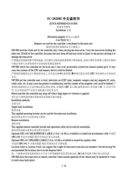
如果安装了 UT-123,那么就可以联接提供的与 UT-123 配套的 GPS 天线。 Connect the GPS antenna as bellow 联接方法如下所示。 Mount the GPS antenna onto a convenient flat surface. The GPS antenna includes magnet mount base, therefore, the antenna can be mounted onto a metal roof/wall, etc. 将 GPS 天线固安装在一块比较方便的平面上。GPS 天线包含磁性的固定基座,因此可以将天线固定在金属顶 棚、侧壁等的上面。 NOTE 注意 When the GPS antenna is connected, only remote installation is allowed. GPS 天线只允许在遥控安装模式下进行安装。 The GPS antenna is not weather-proof construction, therefore, NEVER install the antenna in outdoor. GPS 天线不是防风雨的,因此严禁将其安装在户外。 Important notes when using GPS receiver 使用 GPS 接收器时的注意事项 The GPS antenna is not weather-proof construction, therefore, NEVER install the antenna in outdoor. GPS 天线不是防风雨的,因此严禁将其安装在户外。 Please d o n ot i nstall t he GPS a ntenna cl ose t he T X an tenna. T he t ransmit s ignal m ay cau se G PS r eceiver malfunction. 请不要将 GPS 天线安装在 TX 天线附近,TX 天线的传输信号可能导致 GPS 接收器发生故障。 The GPS signal cannot pass through the metal object.When installing GPS antenna inside a vehicle, we recommend to mount under the front or near glass such as on the dashboard, etc.Please avoid the areas shown in the following: 1)Do not mount where it will block the driver’s view. 2) Do not mount where the air bags could deploy. GPS 信号不能穿透金属物体。当在车辆内部安装 GPS 天线时,我们推荐将其安装在前窗或侧窗玻璃的底部(例 如仪表盘等)。但请避免以下列出的位置: 1)妨碍驾驶员视线的位置; 2)妨碍气囊展开的位置。 The G lobal P ositioning S ystem ( GPS) i s bui lt a nd ope rated by t he U S D efense D epartment.The D epartment i s responsible f or a ccuracy an d maintenance o f t he s ystem.Any ch anges t hat t he Department makes may affect t he accuracy and function of the GPS system. 全球定位系统(GPS)是由美国国防部建立并运行的,美国防部控制其精度并负责系统维护。美国防部做出的任 何改变都可能影响 G可能会影响到车辆正常操作或可能对人身造成伤害的位置 。 NEVER place the transceiver or remote controller where air bag deployment may be obstructed.严禁将主模块或 控制器放置在可能阻碍救生气囊展开的位置 。 DO NOT place the transceiver or remote controller where hot or cold air blows directly onto it. 请不要将主模块或控制器放置在热气或冷气能够直接吹到的位置 。 AVOID placing the transceiver or remote controller in direct sunlight. 请避免将主模块或控制器放置在阳光直射的地方 。 Using the mounting bracket 使用固定架 Drill 4 holes where the mounting bracket is to be installed. 钻 4 个孔用来安装固定架。 Approx 5.5-6 mm(1/4”) when using nuts, approx 2-3 mm(1/8”) when using self-tapping screws. 如果用螺母,孔的直径约 5.5-6 毫米;如果使用木螺丝,孔的直径约 2-3 毫米。 Insert the supplied screws, nuts and washers through the mounting bracket and tighten. 将提供的螺丝、螺母和垫圈插进固定架的正确位置并拧紧。 Adjust the angle for your suitable position. 将角度调整到你自己感觉舒服的位置。
ic-2820-维修手册

CAUTION
NEVER connect the transceiver to an AC outlet or to a DC power supply that uses more than 15 V. This will ruin the transceiver.
DO NOT expose the transceiver to rain, snow or any liquids.
E2820_MANUAL.pdf
The instruction manuals for IC-E2820. The contents of this document is exactly same as supplied instruction manual with the product. You can print it out to make brand new instruction manual any time you want. This document will be very helpful when you want to change or set product setting or condition for adjustment or else.
8. READ the instructions of test equipment thoroughly before connecting equipment to the transceiver.
Icom, Icom Inc. and
logo are registered trademarks of Icom Incorporated (Japan) in the United States, the United
2812中文手册(清华版)
‡‡ 产品预览(PP):在开发阶段的形成和设计中与产品有关的信息,特征数据和其他规格是设计的
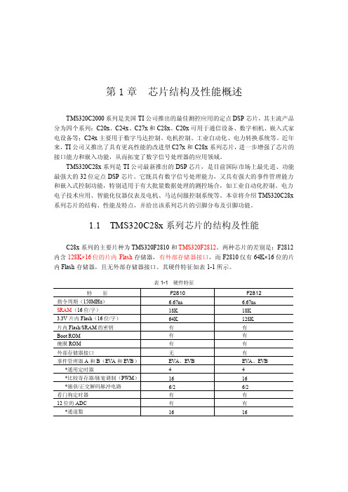
C28x 系列芯片的主要性能如下。 1. 高性能静态 CMOS (Static CMOS )技术 � � � 150MHz (时钟周期 6.67ns) 低功耗(核心电压 1.8V,I/O 口电压 3.3V) Flash 编程电压 3.3V
第1章
芯片结构及性能概述
TMS320C2000 系列是美国 TI 公司推出的最佳测控应用的定点 DSP 芯片,其主流产品 分为四个系列:C20x、C24x 、C27x 和 C28x。C20x 可用于通信设备、数字相机、嵌入式家 电设备等;C24x 主要用于数字马达控制、电机控制、工业自动化、电力转换系统等。近年 来, TI 公司又推出了具有更高性能的改进型 C27x 和 C28x 系列芯片, 进一步增强了芯片的 接口能力和嵌入功能,从而拓宽了数字信号处理器的应用领域。 TMS320C28x 系列是 TI 公司最新推出的 DSP 芯片,是目前国际市场上最先进、功能 最强大的 32 位定点 DSP 芯片。它既具有数字信号处理能力,又具有强大的事件管理能力 和嵌入式控制功能,特别适用于有大批量数据处理的测控场合,如工业自动化控制、电力 电子技术应用、智能化仪器仪表及电机、马达伺服控制系统等。本章将介绍 TMS320C28x 系列芯片的结构、性能及特点,并给出该系列芯片的引脚分布及引脚功能。
·3·
� � � � � � � � � � � � � � � �
�
强大的操作能力 迅速的中断响应和处理 统一的寄存器编程模式 可达 4 兆字的线性程序地址 可达 4 兆字的数据地址 代码高效(用 C/C++ 或汇编语言) 与 TMS320F24x/LF240x 处理器的源代码兼容 128K×16 位的 Flash 存储器 1K×16 位的 OTP 型只读存储器 L0 和 L1 :两块 4K×16 位的单口随机存储器(SARAM ) H0 :一块 8K×16 位的单口随机存储器 M0 和 M1 :两块 1K×16 位的单口随机存储器 带有软件的 Boot 模式 标准的数学表 有多达 1MB 的存储器 可编程等待状态数 可编程读/写选通计数器(Strobe Timing) 三个独立的片选端 支持动态的改变锁相环的频率 片内振荡器 看门狗定时器模块
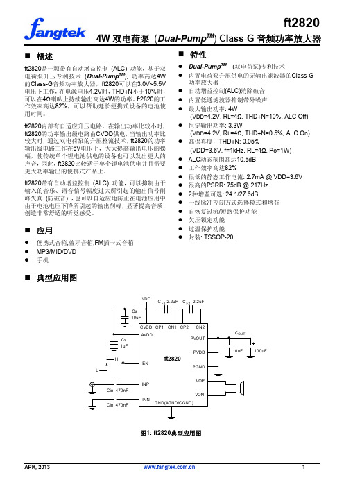
ft2820
1.9 W
3.3
2.9
27.6
24.1
dB
24.1
Sep, 2013
5
ft2820
电气特性(续)
VDD=3.6V, Mode 1, AVDD=1µF, CVDD=10µF, CF1=CF2 =2.2µF, COUT=10µF//100uF, f=1kHz, CIN=470nF, RL=4Ω+33µH, TA=25°C.
4. 在Class-D的输出端可以接简单的磁珠和电容来更好地抑制高频率的EMI,当负载电阻小于6Ω时,可选 择额定电流不小于2A的磁珠,磁珠和电容要尽量地靠近VOP和VON脚。
Sep, 2013
3
功能框图
ft2820
AVD D
C VD D
振荡器
2. 为使ft2820有更大的输出功能,更高的效率,更好的保真度,更低的EMI特性,需要尽量地在AVDD, CVDD和PVDD管脚边上放置合适的退耦电容,电容要尽量地靠近相应的电源脚。
3. 建议AVDD和CVDD之间放置一个小电阻(例如10Ω),减少CVDD端的浪涌电流对AVDD的影响,在PCB 上,CVDD要有低阻抗的接入点,地线走线时要注意输入与输出之间的隔离。
封装热阻 (注 2,3)
封装
TA < +25°C
TA = +70°C
TA = +85°C
TSSOP-20L
4.8W
3.1W
2.6W
Note 2: 芯片的散热脚必须直接焊接到 PCB 的焊盘上,并通过 PCB 的大面积铺铜来帮助散热。
Note 3: 热阻值是在双面 PCB 板上,通过大面积铺铜散热的典型值.
SVR2810 用户手册2011.8.3
ii
补刻 ........................................................................................................12 3.2 光盘校验 ...............................................................................................12 3.3 网络配置 ...............................................................................................12 3.4 清除录像 ...............................................................................................13 3.5 版本信息查看........................................................................................13 3.6 系统维护 ...............................................................................................14
MAX2820EVKIT中文资料
General DescriptionThe MAX2820/MAX2820A and MAX2821/MAX2821A single-chip zero-IF transceivers are designed for the 802.11b (11Mbps) applications operating in the 2.4G Hz to 2.5G Hz ISM band. The transceivers are nearly identical, except the MAX2821 and MAX2821A also provide a low-power shutdown mode and an ana-log voltage reference output. The MAX2820A/MAX2821A are cost-reduced versions, virtually identi-cal in pinout and performance to the MAX2820/MAX2821. The transceivers include all the circuitry required to implement an 802.11b RF-to-baseband transceiver solution, providing a fully integrated receive path, transmit path, VCO, frequency synthesis,and baseband/control interface. Only a PA, RF switch,RF BPF, and a small number of passive components are needed to form the complete radio front-end solution.The ICs eliminate the need for external IF and base-band filters by utilizing a direct-conversion radio archi-tecture and monolithic baseband filters for both receiver and transmitter. They are specifically opti-mized for 802.11b (11Mbps CCK) applications. The baseband filtering and Rx and Tx signal paths support the CCK modulation scheme for BER = 10-5 at the required sensitivity levels.The devices are suitable for the full range of 802.11b data rates (1Mbps, 2Mbps, 5.5Mbps, and 11Mbps) and also the higher-rate 22Mbps PBCC TM standard. The MAX2820 and MAX2821 are available in a 7mm ×7mm 48-lead QFN package. The MAX2820, MAX2821,MAX2820A, and MAX2821A are available in a 48-lead thin QFN package.Applications802.11b 11Mbps WLAN802.11b +22Mbps PBCC High-Data-Rate WLAN 802.11a + b Dual-Band WLAN 2.4GHz ISM Band RadiosFeatureso 2.4GHz to 2.5GHz ISM Band Operationo 802.11b (11Mbps CCK and 22Mbps PBCC) PHY Compatible o Complete RF-to-Baseband TransceiverDirect-Conversion Upconverters and DownconvertersMonolithic Low-Phase-Noise VCO Integrated Baseband Lowpass FiltersIntegrated PLL with 3-Wire Serial Interface Digital Bias Control for External PATransmit Power Control (Range > 25dB)Receive Baseband AGC (Range > 65dB)Complete Baseband Interface Digital Tx/Rx Mode ControlAnalog Receive Level Detection o -97dBm Rx Sensitivity at 1Mbps o -87dBm Rx Sensitivity at 11Mbps o +2dBm Transmit Power (11Mbps CCK)o Single +2.7V to +3.6V Supplyo Low-Current Shutdown Mode (MAX2821 only)o Very Small 48-Pin QFN Package(s)MAX2820/MAX2820A/MAX2821/MAX2821A2.4GHz 802.11b Zero-IF Transceivers________________________________________________________________Maxim Integrated Products 1Ordering Information19-2493; Rev 5; 5/05For pricing, delivery, and ordering information,please contact Maxim/Dallas Direct!at 1-888-629-4642, or visit Maxim’s website at .Pin Configuration/Functional Diagram and Typical Application Circuit appear at end of data sheet.PBCC is a trademark of Texas Instruments, Inc.M A X 2820/M A X 2820A /M A X 2821/M A X 2821A2.4GHz 802.11b Zero-IF TransceiversABSOLUTE MAXIMUM RATINGSDC ELECTRICAL CHARACTERISTICS(MAX2820/MAX2821 EV kit: V CC = +2.7V to +3.6V, RF_GAIN = V IH , 0V ≤V TX_GC ≤+2.0V, 0V ≤V RX_AGC ≤+2.0V, RBIAS = 12k Ω, no input signals at RF and baseband inputs, all RF inputs and outputs terminated into 50Ω, receiver baseband outputs are open, trans-mitter baseband inputs biased at +1.2V, registers set to default power-up settings, T A = -40°C to +85°C, unless otherwise noted.Typical values are at V CC = +2.7V, T A = +25°C, unless otherwise noted.) (Note 1)Stresses beyond those listed under “Absolute Maximum Ratings” may cause permanent damage to the device. These are stress ratings only, and functional operation of the device at these or any other conditions beyond those indicated in the operational sections of the specifications is not implied. Exposure to V CC Pins to GND...................................................-0.3V to +4.2V RF Inputs: RX_RFP, RX_RFN to GND.........-0.3V to (V CC + 0.3V)RF Outputs: TX_RFP, TX_RFN to GND..................-0.3V to +4.2V Baseband Inputs: TX_BBIP, TX_BBIN, TX_BBQP,TX_BBQN to GND ...................................-0.3V to (V CC + 0.3V)Baseband Outputs: RX_BBIP, RX_BBIN, RX_BBQP,RX_BBQN to GND...................................-0.3V to (V CC + 0.3V)Analog Inputs: RX_AGC, TX_GC, TUNE, ROSCN,ROSCP to GND.......................................-0.3V to (V CC + 0.3V)Analog Outputs: PA_BIAS, CP_OUT, VREFto GND.....................................................-0.3V to (V CC + 0.3V)Digital Inputs: RX_ON, TX_ON, SHDNB, CSB, SCLK,DIN, RF_GAIN, RX_1K to GND................-0.3V to (V CC + 0.3V)Bias Voltages: RBIAS, BYP..................................+0.9V to +1.5V Short-Circuit Duration Digital Outputs: DOUT, RX_DET.........10s RF Input Power: RX_RFN, RX_RFP.................................+10dBm Continuous Power Dissipation (T A = +70°C)48-Lead QFN (derate 27.0mW/°C above +70°C)...........2162mW 48-Lead Thin QFN (derate 38.5mW/°Cabove +70°C)...................................................................3077mW Operating Temperature Range ...........................-40°C to +85°C Junction Temperature......................................................+150°C Storage Temperature Range.............................-65°C to +160°C Lead Temperature (soldering, 10s).................................+300°CMAX2820/MAX2820A/MAX2821/MAX2821A2.4GHz 802.11b Zero-IF TransceiversDC ELECTRICAL CHARACTERISTICS (continued)(MAX2820/MAX2821 EV kit: V CC = +2.7V to +3.6V, RF_GAIN = V IH , 0V ≤V TX_GC ≤+2.0V, 0V ≤V RX_AGC ≤+2.0V, RBIAS = 12k Ω, no input signals at RF and baseband inputs, all RF inputs and outputs terminated into 50Ω, receiver baseband outputs are open, trans-mitter baseband inputs biased at +1.2V, registers set to default power-up settings, T A = -40°C to +85°C, unless otherwise noted.AC ELECTRICAL CHARACTERISTICS—RECEIVE MODE(MAX2820/MAX2821 EV kit: V CC = +2.7V to +3.6V, f RF and f LO = 2400MHz to 2499MHz, f OSC = 22MHz or 44MHz, receive baseband outputs = 500mV P-P , SHDNB = RX_ON = V IH , TX_ON = V IL , CSB = V IH , SCLK = DIN = V IL , RF_GAIN = V IH , 0V ≤V RX_AGC ≤+2.0V,RBIAS = 12k Ω, I CP = +2mA, BW PLL = 45kHz, differential RF input matched to 50Ω, registers set to default power-up settings, T A =+25°C, unless otherwise noted. Typical values are at V CC = +2.7V, f LO = 2437MHz, f OSC = 22MHz, unless otherwise noted.) (Note 1)M A X 2820/M A X 2820A /M A X 2821/M A X 2821A2.4GHz 802.11b Zero-IF Transceivers 4_______________________________________________________________________________________AC ELECTRICAL CHARACTERISTICS —RECEIVE MODE (continued)(MAX2820/MAX2821 EV kit: V CC = +2.7V to +3.6V, f RF and f LO = 2400MHz to 2499MHz, f OSC = 22MHz or 44MHz, receive baseband outputs = 500mV P-P , SHDNB = RX_ON = V IH , TX_ON = V IL , CSB = V IH , SCLK = DIN = V IL , RF_GAIN = V IH , 0V ≤V RX_AGC ≤+2.0V,RBIAS = 12k Ω, I CP = +2mA, BW PLL = 45kHz, differential RF input matched to 50Ω, registers set to default power-up settings, T A =AC ELECTRICAL CHARACTERISTICS—TRANSMIT MODEMAX2820/MAX2820A/MAX2821/MAX2821A2.4GHz 802.11b Zero-IF Transceivers (MAX2820/MAX2821EV kit: V CC= +2.7V to +3.6V, f RF and f LO= 2400MHz to 2499MHz, f OSC= 22MHz or 44MHz, transmit baseband inputs = 400mV P-P, SHDNB = TX_ON = V IH, RX_ON = V IL, CSB = V IH, 0V ≤V TX_GC≤+2.0V, RBIAS = 12kΩ, I CP= +2mA, BW PLL= 45kHz, differential RF output matched to 50Ωthrough a balun, baseband input biased at +1.2V, registers set to default power-up set-tings, T A= +25°C, unless otherwise noted. Typical values are at V CC= +2.7V, f LO= 2437MHz, f OSC= 22MHz, unless otherwise noted.)M A X 2820/M A X 2820A /M A X 2821/M A X 2821A2.4GHz 802.11b Zero-IF Transceivers 6_______________________________________________________________________________________AC ELECTRICAL CHARACTERISTICS —SYNTHESIZER(MAX2820/MAX2821 EV kit: V CC = +2.7V to +3.6V, f RF and f LO = 2400MHz to 2499MHz, f OSC = 22MHz or 44MHz, SHDNB = V IH ,CSB = V IH , RBIAS = 12k Ω, I CP = +2mA, BW PLL = 45kHz, registers set to default power-up settings, T A = +25°C, unless otherwise noted. Typical values are at V CC = +2.7V, f LO = 2437MHz, f OSC = 22MHz, unless otherwise noted.) (Note 11)AC ELECTRICAL CHARACTERISTICS —PA BIAS(MAX2820/MAX2821 EV kit: V CC = +2.7V to +3.6V, SHDNB = V IH , TX_ON = V IH , CSB = V IH , PA_BIAS enabled, RBIAS = 12k Ω, regis-ters set to default power-up settings, T = +25°C, unless otherwise noted. Typical values are at V = +2.7V, unless otherwise noted.)AC ELECTRICAL CHARACTERISTICS—SYSTEM TIMINGMAX2820/MAX2820A/MAX2821/MAX2821A2.4GHz 802.11b Zero-IF Transceivers (MAX2820/MAX2821 EV kit: V CC= +2.7V to +3.6V, f RF and f LO= 2400MHz to 2499MHz, f OSC= 22MHz or 44MHz, SHDNB = V IH, CSB = V IH, RBIAS = 12kΩ, I CP= +2mA, BW LOOP= 45kHz, registers set to default power-up settings, T A= +25°C, unless otherwisenoted. Typical values are at V CC= +2.7V, f LO= 2437MHz, f OSC= 22MHz, unless otherwise noted.) (Note 11)(MAX2820/MAX2821 EV kit: V CC= +2.7V to +3.6V, registers set to default power-up settings, T A= +25°C, unless otherwise noted.) (Note 11)Note 3:Noise-figure specification excludes the loss of the external balun. The external balun loss is typically ~0.5dB.Note 4:CCK interferer at 25MHz offset. Desired signal equals -73dBm. Interferer amplitude increases until baseband output from interferer is 10dB below desired signal. Adjacent channel rejection = P interferer- P desired.Note 5:Measured at balun input. Two CW tones at -43dBm with 15MHz and 25MHz spacing from the MAX2820/MAX2821 channel frequency. IP3 is computed from 5MHz IMD3 product measured at the RX I/Q output.Note 6:Two CW interferers at -38dBm with 24.5MHz and 25.5MHz spacing from the MAX2820/MAX2821 channel frequency. IP2 is computed from the 1MHz IMD2 product measured at the RX I/Q output.Note 7:Output power measured after the matching and balun. TX gain is set to maximum.Note 8:Adjacent and alternate channel power relative to the desired signal. TX gain is adjusted until the output power is -1dBm.Power measured with 100kHz video BW and 100kHz resolution BW.Note 9:Time required to reprogram the PLL, change the operating channel, and wait for the operating channel center frequency to settle within ±10kHz of the nominal (final) channel frequency.Note 10:Relative amplitude of reference spurious products appearing in the TX RF output spectrum relative to a CW tone at0.5MHz offset from the LO.Note 11:Min/max limits are guaranteed by design and characterization._______________________________________________________________________________________7M A X 2820/M A X 2820A /M A X 2821/M A X 2821A2.4GHz 802.11b Zero-IF Transceivers 8_______________________________________________________________________________________Typical Operating Characteristics(MAX2820/MAX2821 EV kit, V CC = +2.7V, f BB = 1MHz, f LO = 2450MHz, receive baseband outputs = 500mV P-P , transmit base-band inputs = 400mV P-P , I CP = +2mA, BW PLL = 45kHz, differential RF input/output matched to 50Ωthrough a balun, baseband input biased at +1.2V, registers set to default power-up settings, T A = +25°C, unless otherwise noted.)SUPPLY CURRENT vs. TEMPERATURETEMPERATURE (°C)I C C (m A )603510-151020304050607080901000-4085SUPPLY CURRENT vs. SUPPLY VOLTAGEV CC (V)I C C (m A )3.33.010203040506070809010002.73.6V RX_AGC (V)R X V O L T A G E G A I N (d B )1.51.00.5204060801001202.0RECEIVER VOLTAGE GAIN vs. GAIN-CONTROL VOLTAGERF FREQUENCY (MHz)R X V O L T A G E G A I N (d B )2480246024202440510152025303540024002500RECEIVER VOLTAGE GAIN vs. RF FREQUENCYRX GAIN (dB)N O I S E F I G U R E (d B )8060402051015202530354045500100RECEIVER NOISE FIGURE vs. GAINP IN (dBm)L O G I C L E V E L-40-45-50-55-60-65-35RECEIVER DETECTOR HYSTERESISvs. INPUT POWERFREQUENCY (kHz)N O R M A L I Z E D R E S P O N S E (d B )10010-80-70-60-50-40-30-20-10010-9011000RECEIVER FILTER RESPONSE(1kHz TO 1MHz)FREQUENCY (MHz)N O R M A L I Z E D R E S P O N S E (d B )10-80-70-60-50-40-30-20-10010-901100RECEIVER FILTER RESPONSE(1MHz TO 100MHz)RECEIVER LEAKAGE SPECTRUMFREQUENCY (GHz)R E C E I V E R L E A K A G E P O W E R (d B m )7.26.44.8 5.61.6 2.4 3.2 4.00.8-100-90-80-70-60-50-40-30-20-10-12008.0V RF_GAIN = V IH f LO = 2400MHzMAX2820/MAX2820A/MAX2821/MAX2821A2.4GHz 802.11b Zero-IF Transceivers_______________________________________________________________________________________9RECEIVER BASEBAND OUTPUT SPECTRUMFREQUENCY (MHz)B A S E B A N D O U T P U T P O W E R (d B m )45405101525302035-70-60-50-40-30-20-100-8050V RF_GAIN = V IH RX GAIN = 50dB f BB = 5MHz f LO = 2450MHzFREQUENCY (MHz)T X O U T P U T P O W E R (d B m )24802460242024400.51.01.52.02.53.03.54.0024002500TRANSMITTER OUTPUT POWERvs. FREQUENCYV CC (V)T X O U T P U T P O W E R (d B m )3.33.00.51.01.52.02.53.03.54.002.73.6TRANSMITTER OUTPUT POWERvs. SUPPLY VOLTAGE-90-80-70-60-50-40-30-20-10-33-11-22112233TRANSMITTER OUTPUT SPECTRUMFREQUENCY OFFSET FROM CARRIER (MHz)T X O U T P U T P O W E R (d B m )-80-60-70-40-50-30-200-101000.8 1.6 2.4 3.2 4.0 4.8 5.6 6.47.28.0TRANSMITTER OUTPUT SPECTRUMFREQUENCY (GHz)T X O U T P U T P O W E R (d B m )CW SIGNAL f BB = 3.3MHz f LO = 2450MHzV TX_GC (V)N O R M A L I Z E D G A I N (d B )1.51.00.5-30-25-20-15-10-505-352.0TRANSMITTER GAIN vs. GAIN-CONTROL VOLTAGETypical Operating Characteristics (continued)(MAX2820/MAX2821 EV kit, V CC = +2.7V, f BB = 1MHz, f LO = 2450MHz, receive baseband outputs = 500mV P-P , transmit base-band inputs = 400mV P-P , I CP = +2mA, BW PLL = 45kHz, differential RF input/output matched to 50Ωthrough a balun, baseband input biased at +1.2V, registers set to default power-up settings, T A = +25°C, unless otherwise noted.)M A X 2820/M A X 2820A /M A X 2821/M A X 2821A2.4GHz 802.11b Zero-IF Transceivers 10______________________________________________________________________________________-50-60-70-80-90-100-110-120-13010010k100k1k1MCLOSED-LOOP PHASE NOISE vs. OFFSET FREQUENCYOFFSET FREQUENCY (Hz)P H A S E N O I S E (d B c /H z )f LO = 2450MHz BW LOOP = 45kHz I CP = 2mA φINT = 2.1°RMSMAX2820/MAX2821("A" VERSION)MAX2820/MAX2821VCO/PLL SETTING TIMETIME (µs)F R E Q U E N C Y E R R O R (k H z )-40-30-20-1001020304050-5036032024028080120160200400400BW LOOP = 45kHzf LO = 2499MHz TO 2400MHzTypical Operating Characteristics (continued)(MAX2820/MAX2821 EV kit, V CC = +2.7V, f BB = 1MHz, f LO = 2450MHz, receive baseband outputs = 500mV P-P , transmit baseband inputs = 400mV P-P , I CP = +2mA, BW PLL = 45kHz, differential RF input/output matched to 50Ωthrough a balun, baseband input biased at +1.2V, registers set to default power-up settings, T A = +25°C, unless otherwise noted.)TRANSMITTER BASEBAND FILTER RESPONSEFREQUENCY (MHz)N O R M A L I Z E D R E S P O N S E (d B )908070605040302010-50-40-30-20-10010-60100f LO = 2450MHzLO FREQUENCY vs. TUNING VOLTAGEV TUNE (V)L O F R E Q U E N C Y (G H z )2.01.51.00.52.252.302.352.402.452.502.552.602.652.202.5-50-1401100010010OPEN-LOOP PHASE NOISE vs. OFFSET FREQUENCY-110-130-70-90-40-100-120-60-80OFFSET FREQUENCY (kHz)P H A S E N O I S E (d B c /H z )MAX2820/MAX2820A/MAX2821/MAX2821A Pin Configuration/Functional DiagramM A X 2820/M A X 2820A /M A X 2821/M A X 2821ASPI and QSPI are trademarks of Motorola, Inc. MICROWIRE is a trademark of National Semiconductor Corp.MAX2820/MAX2820A/MAX2821/MAX2821AM A X 2820/M A X 2820A /M A X 2821/M A X 2821APin Description (continued)Changes in “A” VersionThe MAX2820A/MAX2821A are cost-reduced versions of the original MAX2820/MAX2821, intended as a drop-in replacement —no changes to PC board layout, BOM,or control software are required. Functionally, the “A ”version removes unused functions and programmability while maintaining virtually identical performance char-acteristics. The changes are detailed below.SynthesizerThe original device has the ability to program the charge-pump source/sink current (±1mA or ±2mA); the “A ” version sets the charge-pump current at ±2mA, and bit SYNTH:D6 (ICP) should now always be pro-grammed to be 1.Receive FilterThe original device has the ability to control the base-band LPF corner; the “A ” version sets the LPF corner at 8.0MHz. Register bits RECEIVE:D2–D0 are now “don ’t cares.”Receive-Level Detector (RSSI)The original device has a receive-level detect output (pin 43, “RX_DET ”); the “A ” version removes this functionality.Pin 43 is a no-connect (N.C.) on the “A ” version.MAX2820/MAX2820A/MAX2821/MAX2821AOperating ModesThe MAX2820/MAX2821 have four primary modes of operation: shutdown, standby, receive active, and transmit active. The modes are controlled by the digital inputs SHDNB, TX_ON, and RX_ON. Table 1 shows the operating mode vs. the digital mode control input.Shutdown ModeShutdown mode is achieved by driving SHDNB low. In shutdown mode, all circuit blocks are powered down,except for the serial interface circuitry. While the device is in shutdown, the serial interface registers can still be loaded by applying V CC to the digital supply voltage (VCC_DIG). All previously programmed register values are preserved during the shutdown mode, as long as VCC_DIG is applied.Standby ModeStandby mode is achieved by driving SHDNB high and RX_ON and TX_ON low. In standby mode, the PLL,VCO, LO generator, LO buffer, LO quadrature, and fil-ter autotuner are powered on by default. The standby mode is intended to provide time for the slower-settling circuitry (PLL and autotuner) to turn on and settle to the correct frequency before making RX or TX active. The 3-wire serial interface is active and can load registervalues at any time. Refer to the serial-interface specifi-cation for details.Receive ModeReceive mode is enabled by driving the digital inputs SHDNB high, RX_ON high, and TX_ON low. In receive mode, all receive circuit blocks are powered on and all VCO, PLL, and autotuner circuits are powered on. None of the transmit path blocks are active in this mode. Although the receiver blocks turn on quickly, the DC offset nulling requires ~10µs to settle. The receiver signal path is ready ~10µs after a low-to-high transition on RX_ON.Transmit ModeTransmit mode is achieved by driving the digital inputs SHDNB high, RX_ON low, and TX_ON high. In transmit mode, all transmit circuit blocks are powered on and all VCO, PLL, and autotuner circuits are powered on.None of the receive path blocks is active in this mode.Although the transmitter blocks turn on quickly, the baseband DC offset calibration requires ~2.2µs to complete. In addition, the TX driver amplifier is ramped from the low-gain state (minimum RF output) to high-gain state (peak RF output) over the next 1µs to 2µs.The transmit signal path is ready ~4µs after a low-to-high transition on TX_ON.Figure 1. MAX2820/MAX2821 Serial-Interface Timing DiagramM A X 2820/M A X 2820A /M A X 2821/M A X 2821AProgrammable RegistersThe MAX2820/MAX2820A and MAX2821/MAX2821A (the MAX2820 family) contain programmable registers to control various modes of operation for the major cir-cuit blocks. The registers can be programmed through the 3-wire SPI/QSPI/MICROWIRE-compatible serial port. The MAX2820 family includes five programmable registers:1)Test register (always program as in Table 2).2)Block-enable register 3)Synthesizer register 4)Channel frequency register 5)Receiver settings register 6)Transmitter settings registerEach register consists of 16 bits. The four most signifi-cant bits (MSBs) are the register ’s address. The twelve least significant bits (LSBs) are used for register data.Table 2 summarizes the register configuration. A detailed description of each register is provided in Tables 3–6.Data is shifted in the MSB first. The data sent to the transceiver, in 16-bit words, is framed by CSB. When CSB is low, the clock is active and data is shifted with the rising edge of the clock. When CSB transitions to high, the shift register is latched into the register select-ed by the contents of the address bits. Only the last 16bits shifted into the device are retained in the shift reg-ister. No check is made on the number of clock pulses.Figure 1 documents the serial interface timing for the MAX2820 family.Power-Up Default StatesThe devices provide power-up loading of default states for each of the registers. The states are loaded on a VCC_DIG supply voltage transition from 0V to V CC . The default values are retained until reprogrammed through the serial interface or the power supply voltage is taken to 0V. The default state of each register is described in Table 3. Note:Putting the IC in shutdown mode does not change the contents of the programming registers.Block-Enable RegisterThe block-enable register permits individual control of the enable state for each major circuit block in the transceiver.The actual enable condition of the circuit block is a logical function of the block-enable bit setting and other control input states. Table 4 documents the logical definition of state for each major circuit block.Synthesizer RegisterThe synthesizer register (SYNTH) controls the reference frequency divider and charge-pump current of the PLL.See Table 5 for a description of the bit settings.Channel Frequency RegisterThe channel frequency register (CHANNEL) sets the RF carrier frequency for the radio. The channel is pro-grammed as a number from 0 to 99. The actual frequency is 2400 + channel in MHz. The default setting is 37 for 2437MHz. See Table 6 for a description of the bit settings.Receiver Settings Register (MAX2820/MAX2821 Only)The receive settings register (RECEIVE) controls the receive filter -3dB corner frequency, RX level detector midpoint, and VG A DC offset nulling parameters. The defaults are intended to provide proper operation.Table 2. Programming Register Definition Summary (Address and Data)MAX2820/MAX2820A/MAX2821/MAX2821ATable 4. Block-Enable Register (ENABLE)M A X 2820/M A X 2820A /M A X 2821/M A X 2821ATable 7a. Receive Settings Register (RECEIVE), (MAX2820/MAX2821 Only)Table 5. Synthesizer Register (SYNTH)Table 6. Channel Frequency Block Register (CHANNEL)fied if desired. Do not reprogram VGA DC offset nulling parameters. These settings were optimized during devel-opment. See Table 7 for a description of the bit settings.Transmitter Settings Register The transmitter settings register (TRANSMIT) controls the 4-bit PA bias DAC. The 4 bits correspond to a PA bias current between 0 and full scale (~300µA). See Table 8 for the bit settings.Applications InformationReceive PathLNA The RX_RF inputs are high-impedance RF differential inputs AC-coupled on-chip to the LNA. The LNA inputs require external impedance matching and differential to single-ended conversion. The balanced to single-ended conversion and interface to 50Ωis achieved through the use of an off-chip 2:1 balun transformer, such as the small surface-mount baluns offered by Murata and TOKO. In the case of the 2:1 balun, the RX RF input must be impedance-matched to a differen-tial/balanced impedance of 100Ω. A simple LC network is sufficient to impedance-match the LNA to the balun. The Typical Application Circuit shows the balun, induc-tors, and capacitors that constitute the matching net-work. Refer to the MAX2820/MAX2821 EV kit schematic for component values of the matching network.The line lengths and parasitics have a noticeable impact on the matching element values in the board-level circuit. Some empirical adjustment of LC component values is likely. Balanced line layout on the differential input traces is essential to maintaining good IP2 performance and RF common-mode noise rejection.controlled by the logic signal applied to RF_G AIN. RF_G AIN high enables the high-gain mode, and RF_GAIN low enables the low-gain mode. The LNA gain step is nominally 30dB. In most applications, RF_GAIN is connected directly to a CMOS output of the baseband IC, and the baseband IC controls the state of the LNA gain based on the detected signal amplitude.Receiver Baseband Lowpass Filtering The on-chip receive lowpass filters provide the steep filtering necessary to attenuate the out-of-band (>11MHz) interfering signals to sufficiently low levels to preserve receiver sensitivity. The filter frequency response is precisely controlled on-chip and does not require user adjustment. In the MAX2820/MAX2821, a provision is made to permit the -3dB corner frequency and entire response to be slightly shifted up or down in frequency. This is intended to offer some flexibility in trading off adjacent channel rejection vs. passband distortion. The filter -3dB frequency is programmed through the serial interface. The specific bit setting vs. -3dB frequency is shown in Table 7. The typical receive baseband filter gain vs. frequency profile is shown in the Typical Operating Characteristics.Receive Gain Control and DC Offset Nulling The receive path gain is varied through an external volt-age applied to the pin RX_AG C. Maximum gain is at V RX_AGC= 0V and minimum gain is at V RX_AGC= 2V. The RX_AG C input is a high-impedance analog input designed for direct connection to the RX_AG C DAC output of the baseband IC. The gain-control range, which is continuously variable, is typically 70dB. The gain-control characteristic is shown in the TypicalTable 8. Transmit Settings Register (TRANSMIT)MAX2820/MAX2820A/MAX2821/MAX2821AM A X 2820/M A X 2820A /M A X 2821/M A X 2821AOperating Characteristics section graph Receiver Voltage Gain vs. Gain-Control Voltage.Some local noise filtering through a simple RC network at the input is permissible. However, the time constant of this network should be kept sufficiently low in order not to limit the desired response time of the RX gain-control function.Receiver Baseband Amplifier OutputsThe receiver baseband outputs (RX_BBIP, RX_BBIN,RX_BBQP, and RX_BBQN) are differential low-imped-ance buffer outputs. The outputs are designed to be directly connected (DC-coupled) to the in-phase (I) and quadrature-phase (Q) ADC inputs of the baseband IC.The RX I/Q outputs are internally biased to +1.2V com-mon-mode voltage. The outputs are capable of driving loads up to 5k Ω|| 5pF with the full bandwidth baseband signals at a differential amplitude of 500mV P-P .Proper board layout is essential to maintain good bal-ance between I/Q traces. This provides good quadra-ture phase accuracy.Receiver Power Detector (MAX2820/MAX2821 Only)The receiver level detector is a digital output from an internal threshold detector that is used to determine when to change the LNA gain state. In most applications,it is connected directly to a comparator input of the base-band IC. The threshold level can be programmed through the MAX2820/MAX2821 control software.Transmit PathTransmitter Baseband InputsThe transmitter baseband inputs (TX_BBIP, TX_BBIN,TX_BBQP, and TX_BBQN) are high-impedance differ-ential analog inputs. The inputs are designed to be directly connected (DC-coupled) to the in-phase (I) and quadrature-phase (Q) DAC outputs of the baseband IC.The inputs must be externally biased to +1.2V common-mode voltage. Typically, the DAC outputs are current outputs with external resistor loads to ground. I and Q are nominally driven by a 400mV P-P differential base-band signal.Proper board layout is essential to maintain good bal-ance between I/Q traces. This provides good quadra-ture phase accuracy by maintaining equal parasitic capacitance on the lines. In addition, it is important not to expose the TX I/Q circuit board traces going from the digital baseband IC to the TX_BB inputs. The lines should be shielded on an inner layer to prevent cou-pling of RF to these TX I/Q inputs and possible enve-lope demodulation of the RF signal.Transmit Path Baseband Lowpass FilteringThe on-chip transmit lowpass filters provide the filtering necessary to attenuate the unwanted higher-frequency spurious signal content that arises from the DAC clock feedthrough and sampling images. In addition, the filter provides additional attenuation of the second sidelobe of signal spectrum. The filter frequency response is set on-chip. No user adjustment or programming is required. The Typical G ain vs. Frequency profile is shown in the Typical Operating Characteristics .Transmitter DC Offset CalibrationIn a zero-IF system, in order to achieve low LO leakage at the RF output, the DC offset of the TX baseband sig-nal path must be reduced to as near zero as possible.G iven that the amplifier stages, baseband filters, and TX DAC possesses some finite DC offset that is too large for the required LO leakage specification, it is necessary to “null ” the DC offset. The MAX2820 family accomplishes this through an on-chip calibration sequence. During this sequence, the net TX baseband signal path offsets are sampled and cancelled in the baseband amplifiers. This calibration occurs in the first ~2.2µs after TX_ON is taken high. During this time, it is essential that the TX DAC output is in the 0V differential state. The calibration corrects for any DAC offset.However, if the DAC is set to a value other than the 0V state, then an offset is erroneously sampled by the TX offset calibration. The TX DAC output must be put into the 0V differential state at or before the time TX_ON is taken high.Power-Amplifier Driver OutputThe TX_RF outputs are high-impedance RF differential outputs directly connected to the driver amplifier. The outputs are essentially open-collector outputs with an on-chip inductor choke connected to VCC_DRVR. The power-amplifier driver outputs require external imped-ance matching and differential to single-ended conver-sion. The balanced to single-ended conversion and interface to 50Ωis achieved through the use of an off-chip 4:1 balun transformer, such as one from Murata or TOKO. In this case, the TX RF output must be imped-ance-matched to a differential/balanced impedance of 200Ω. The Typical Application Circuit shows the balun,inductors, and capacitors that constitute the matching network of the power amplifier driver outputs. The out-put match should be adjusted until the return loss at the balun output is >10dB.。
LDE(Q)安装使用说明书
LD128E(Q)安装使用说明书2003/01一.系统介绍JB-QB/LD128E(Q)联动型中文火灾报警控制器(以下简称LD128E(Q))是智能化的二总线火灾自动报警设备,采用中文液晶显示,满足《消防联动控制设备通用技术条件GB16806-1997》规范。
LD128E(Q)集报警及联动控制于一体,主要针对中、小型消防工程项目设计,广泛应用于宾馆、公寓、商场、餐饮娱乐场所、工厂等,同时它可作为大型工程的区域火灾报警控制器使用。
LD128E(Q)联动控制器可配接4个回路,每回路可混接256个探测器、联动模块或区显。
即LD128E(Q)联动控制器总容量为1024点,其中探测器、联动模块和区显的比例可自由调配。
同时它除有一组公共火警继电器输出节点外,还有6路继电器有源输出。
LD128E(Q)联动控制器具有一个CAN总线接口,可与我公司生产的其它控制器形成对等网络,同时具备RS232接口,可与CRT、楼宇自动化设备及远程消防管理系统相连。
1.1功能简介1.1.1液晶显示LD128E(Q)采用全液晶中文显示,并配发光二极管指示系统关键状态信息。
液晶的使用使用户方便快捷地查询系统火灾信息及系统工作状态,它的全中文及菜单功能使用户不必花费大量的时间来学习系统的操作方法,只要查询菜单就能进行操作。
方便快捷的按键方式,使您能够快速的查询到您所要的信息。
1.1.2布线方式LD128E(Q)采用二总线回路,总线设计可减少工程布线及方便工程安装调试。
同时支持分支、单支、树型分支、环形等多种布线方式。
1.1.3节点输出系统具备6组可编程继电器有源输出,可根据用户的需要设置启动逻辑。
继电器的逻辑表达式可直接从键盘输入,无需任何专业人员即可在现场进行编程,特别适合使用单位和安装工程公司人员在现场调试操作。
1.1.4火警记录系统具有黑匣子功能,可存储1000条纪录,用户可方便地在系统菜单中调出所存储的火警纪录。
这种方式先进、可靠、存储记录时间长。
SHARP复印机_2820N使用说明书

这里 “打印服务器”指直接和机器相连的一台计算机,“客户端”指连接在同一网络中的任何其它计算机。
检选框
“取消”按钮
单击检选框可激活或取消此 功能。 打印设置图象
显示所选打印设置的效果。 下拉列表
可以让您从选项列表中选择 一个项目。 进纸盒图象
在 “纸张”标签的 “纸张
单击此按钮可以退出此对话 框,并且不会更改设置。 “应用”按钮
单击此按钮可以保存您的设 置,同时对话框不会关闭。
Windows NT 4.0 中 没有 “应用”按钮。 当您从应用程序打 开此窗口时,“应
让您逐页向前浏览。
让您逐页返回浏览。
3
目录
导言 如何使用联机手册
1 打印
2 2 打印机共享
3
利用 Windows 网络共享打印机
14
共享打印机设置
15
客户端设置
16
基本打印 利用 “开始”按钮打开打印驱动程序 打印驱动程序设置 多页合一打印 使打印图象适应纸张 180 度旋转打印图象 打印水印 打印状态窗口简介
☞有关打开打印驱动程序的详细信息请参阅基本打印。
如何打印水印
从 “水印”下拉列表中,选择准备打印在文件上的水印 (例如 “秘密”),然后开始打印。
打印举例
您可以输入文本以创建自定义水印。有关水印设置的详情,请查看打印驱动程序帮助。
☞打印驱动程序设置
12
1 打印 打印状态窗口简介
开始打印时,打印状态窗口自动打开。 打印状态窗口是用于监视机器和显示正在打印的原稿名称和错误信息的工具。
AR-2820N/2820NZ 联机手册
单击 “开始”按钮。
导言
本手册描述了 AR-2820N/2820NZ 数码复合机中的打印功能。 ● 有关以下主题的信息,请参阅数码复合机的操作手册。 机器的基本操作 (添加纸张,更换墨粉盒,使用外围设备) 复印功能 解决打印问题 规格 ● 本手册中出现 “AR-XXXX”的地方,请用机器型号的名称替代 “XXXX”。 ● 本手册中出现的屏幕图象和操作步骤主要针对 Windows® XP 环境,其它版本 Windows® 操作系统中出现的屏幕图象可能和手册中 的有所不同。 ● 有关使用操作系统的信息,请参阅您的操作系统手册或在线帮助。
HSMS-2820中文资料

∆VF - FORWARD VOLTAGE DIFFERENCE (mV) IF - FORWARD CURRENT (mA)
30
30
30
30
10
85°C
1
55°C
25°C
–5°C 0.1
–35°C
0.01 0.1 0.2 0.3 0.4 0.5 0.6 0.7 0.8 0.9
VF - FORWARD VOLTAGE (V)
HSMS-286X
7.0 0.18 0.69 10E-5 5.0 x 10E -8 1.08 5.0 0.65
2 0.5
4
IF - FORWARD CURRENT (mA)
∆VF - FORWARD VOLTAGE DIFFERENCE (mV)
IF - FORWARD CURRENT (mA)
Typical Parameters at TA = 25°C (unless otherwise noted), Single Diode
Note that HP’s manufacturing techniques assure that dice found in pairs and quads are taken from adjacent sites on the wafer, assuring the highest degree of match.
temperature.
Quad Capacitance
Capacitance of Schottky diode quads is measured using an HP4271 LCR meter. This instrument effectively isolates individual diode branches from the others, allowing accurate capacitance measurement of each branch or each diode. The conditions are: 20 mV R.M.S. voltage at 1 MHz. HP defines this measurement as “CM”, and it is equivalent to the capacitance of the diode by itself. The equivalent diagonal and adjacent capacitances can then be calculated by the formulas given below.
苏州科达 NVR2820网络硬盘录像机 说明书
KEDACOM声明苏州科达科技有限公司版权所有,保留一切权利未经本公司明确书面许可,不得以任何形式或通过任何电子或机械方式,复制或传播本文档的任何部分用于任何用途。
在法律上,复制包括翻译为其它语言或转换为其它格式。
Kedacom® 为科达科技有限公司的注册商标。
KDV™、KDM™ 和KVP是科达科技有限公司在中国和其他各个国家/地区的商标,不得仿冒。
我们尽最大努力来保证本手册信息的正确性。
由于设备升级或其他某些原因造成信息更改,恕不另行通知。
获取最新信息请登录。
前 言读者对象z操作人员z维护人员内容介绍本手册由正文和附录两大部分组成,正文主要对产品功能、性能、安装、使用方法和注意事项等进行介绍,附录则是正文的补充,介绍内置硬盘的安装方法和设备快速配置向导。
第一章 产品概述,概要介绍产品的功能和主要技术指标;第二章 设备安装,介绍安装要求和最小设备安装方法;第三章 系统操作,介绍遥控器和常用的系统操作方法;第四章 菜单导航,介绍全部菜单功能;第五章 常见故障与解决方法,给出常见的故障和排除方法。
本书约定表示需要用户特别注意的地方,如不按照方法操作,可能带来不良后果。
宋体加粗:主要功能、界面参数或归纳总结。
目 录1产品概述 (1)1.1 简介 (1)1.2 功能特性 (1)1.2.1 产品功能 (2)1.2.2 技术指标 (4)2设备安装 (7)2.1 安装要求 (7)2.1.1 电源 (7)2.1.2 报警电压 (7)2.1.3 温湿度、大气压 (8)2.1.4 环境要求 (8)2.2 面板介绍 (8)2.2.1 前面板 (8)2.2.2 后面板 (9)2.3 最小设备安装 (10)2.3.1 最小设备安装图 (10)2.3.2 安装步骤 (11)2.4 快速配置 (12)2.4.1 配置NVR参数 (12)2.4.2 配置前端参数 (14)2.4.3 自动组网 (18)2.4.4 添加终端 (19)2.4.5 配置验证 (20)3系统操作 (23)3.1 遥控器 (24)3.2 开始使用 (26)3.3 设备控制 (28)3.3.1 设置NVR编号 (28)3.3.2 遥控器控制 (29)3.4 登录 (29)3.5 视频监控 (29)3.5.1 视频选看 (31)3.5.2 云台控制 (32)3.5.3 画面回放 (33)3.5.4 图像抓拍 (34)3.5.5 录像模式 (35)3.5.6 通道轮巡 (36)3.5.7 图像调节 (38)3.5.8 画面风格 (38)3.5.9 画面预案 (39)3.5.10 预案轮巡 (40)3.5.11 TV输出调节 (41)3.5.12 录像查询 (42)3.5.13 下一监控点 (42)3.6 录像放像 (43)3.6.1 录像管理 (43)3.6.2 录像控制 (50)3.6.3 定时录像 (51)3.6.4 录像策略 (53)3.7 抓拍管理 (55)3.7.1 图像查询 (55)3.7.2 抓拍设置 (57)3.8 设备管理 (58)3.8.1 添加设备 (58)3.8.2 删除设备 (60)3.8.3 修改名称 (60)3.8.4 设备状态 (61)3.8.5 重启前端 (61)3.8.6 参数设置 (62)3.9 告警管理 (63)3.9.1 告警输入 (63)3.9.2 业务告警 (64)3.9.3 系统告警 (66)3.9.4 告警状态 (67)3.9.5 历史告警查询 (67)3.10 电视墙管理 (68)3.10.1 电视墙通道编辑 (69)3.10.2 电视墙通道轮巡 (70)3.11 用户管理 (71)3.11.1 添加用户 (72)3.11.2 修改用户 (73)3.11.3 删除用户 (73)3.11.4 停用用户 (73)3.11.5 修改密码 (74)3.12 日志管理 (75)3.13 系统管理 (76)3.13.1 常规设置 (76)3.13.2 平台参数 (77)3.13.3 网络设置 (79)3.13.4 串口设置 (82)3.13.5 系统信息 (83)3.13.6 恢复出厂 (84)3.13.7 磁盘管理 (85)3.13.8 升级系统 (86)3.13.9 网络测试 (90)3.13.10 TV输出调节 (91)3.13.11 关闭系统 (91)3.13.12 NAT参数 (92)4菜单导航 (95)4.1 菜单结构 (95)4.2 部分菜单解释 (95)5常见故障与分析 (97)附录 (99)1硬盘安装方法 (99)2拨号网络配置 (101)2.1 设置PPPoE (101)2.2 配置DDNS (102)3NAT设置 (103)3.1 NC位于NAT中 (103)3.2 NVR位于NAT中 (103)3.2.1 设置NAT (103)3.2.2 NVR上的设置 (104)3.2.3 NC上的设置 (105)3.3 NVR和NC在不同的NAT中 (106)3.4 前端(PU)和NVR在不同NAT中 (106)3.4.1 NAT上的设置 (106)3.4.2 NVR上的设置 (107)3.4.3 PU上的设置 (108)术语表 (111)1产品概述NVR2820网络硬盘录像机是苏州科达科技有限公司开发的拥有自主知识产权的产品。
IDT72T20128L7BB资料

COMMERCIAL AND INDUSTRIAL TEMPERATURE RANGES
PIN CONFIGURATIONS
A1 BALL PAD CORNER
A
VCC VCC DNC D1 D4 D7 D9 GND GND Q1 Q3 Q5 Q7 Q9 VDDQ VDDQ
B
DNC DNC DNC D2 D5 D8 HSTL GND GND Q0 Q2 Q4 Q6 Q8 DNC DNC
F
TCK TMS TDO VDDQ VDDQ RCS RT REN
G
WCLK FWFT PAF VDDQ GND GND GND GND GND VDDQ OE RCLK
H
WEN WCS FF/IR VDDQ GND GND GND GND GND VDDQ SCLK SI
J
MRS FSEL1 FSEL0 GND GND GND GND GND GND VDDQ SEN SREN
HSTL I/0 CONTROL
OE
EREN
5996 drw01
Q0 -Qn (x20, x10)
ERCLK
IDT and the IDT logo are registered trademarks of Integrated Device Technology, Inc. The TeraSync is a trademark of Integrated Device Technology, Inc.
DECEMBER 2003
DSC-5996/8
元器件交易网
IDT72T2098/108/118/128 2.5V HIGH-SPEED TeraSync™ DDR/SDR FIFO 20-BIT/10-BIT CONFIGURATIONS 32K x 20/64K x 10, 64K x 20/128K x 10, 128K x 20/256K x 10, 256K x 20/512K x 10
LDE2、LDE1、LDE系列多功能表数码版
10
八、菜单流程图
1、菜单的组织结构如下,用户可根据实际情况选择适当的编程设置参数。
11
2、可选功能菜单流程
12
3、流程图部分解释说明
第1层
第2层
第3层
第4层
描述
SYS
输入设置 -In.-
通讯参数设 置 bUS
2
显示三相电流 Ia、Ib、Ic 单位为 A, 在 K 亮的情况下为 kA;在 M 灯亮的情况 下为 MA。左图中 Ia=5.000A、Ib=5.000A、 Ic=5.000A。
8
显示总有功功率 P、总无功功率 Q、总
3
功率因数 PF。左图中 P=5.700kW、Q=
北京中电力达节能科技有限公司 LDE 系列多功能电力仪表
(LED 显示方式)
使用说明书
多功能网络电力仪表用户手册
一、概述
我公司推出的多功能电力仪表系列(LED 显示方式), 包括 12 型、96 型两种开孔尺寸 的产品,具有可编程测量、显示、变送输出、数字通讯和电能脉冲输出等功能,能够完成电 量测量、电能计量、数据显示、采集及传输,可广泛应用变电站自动化、配电自动化、智能 建筑、企业内部电能测量、管理、考核。测量精度为 0.5 级,实现 LED 现场显示和远程 RS-485 数字接口通讯(采用 MODBUS-RTU 通讯协议)。
二、性能参数
输 入 测 量 显 示
电源
输出
环境 安全
性能
配电网络 额定值
电 过负荷
功耗
压 阻抗
精度 额定值 电 过负荷 功耗 流 阻抗 精度 频率 功率 电能 显示 工作范围 功耗 数字接口 脉冲输出
开关量输入
北京利达LDE联动编程手册

JB-QB/LD128E(Q) 火灾报警控制器(联动型)利达安信-自动报警系统-火灾报警控制系列北京利达安信数码科技有限公司利达安信-自动报警系统-火灾报警控制系列【详细说明】JB-QB/LD128E(Q) 火灾报警控返回>>制器(联动型)JB-QB/LD128E(Q)智能型中文火灾报警控制器是智能化的二总线火灾报警控制器,分四个探测回路,最大设备点数为4096点。
该控制器采用单片机控制技术及多处理器工作方式,除了可以单独使用外,也可以实现多机无主从方式组成对等网络,相互实现冗余备份。
该系统配合我公司LD3000E系列探测器,LD6800E系列控制模块及其它相关设备,广泛应用于大、中型消防工程项目。
经过中国消防产品质量认证委员会及质控中心依照GB4717-93和GB16806-1997标准的检验,取得消防产品安全认证标志。
功能:<>采用无主从方式的对等网络架构设计,每台控制器可显示网络内所有设备工作情况。
可实现多机冗余备份,一台控制器发生故障,可由其他控制器接管<>网络容量:64台控制器、256回路、65536个报警/制点、手动控制盘64块(目前最大2048路)<>本机容量:4~16回路、最大4096个报警/控制点、手动控制盘1块(616块<>自有或通过模块,具有RS232/485通讯端口;具备标准的EtherNet网络接口,支持TCP/IP协议,可方便联入楼控或其他设备<>可实现WEB远程服务;通过Internet实现远程监控<>可任意采用主机和笔记本方式进行设置<>采用CANBus通讯方式,通讯稳定可靠<>具有黑匣子功能,存贮1000条数据<>配合总线设备自动编号;记录烟雾/温度输出曲线和数据;简易方式中文编址;报警灵活阈值设定<>全中文液晶屏显示主要信息与内容,指示灯指示关键状态;中文打印信息输出<>外部设备可通过总线直接控制,也可通过多线手动盘控制<>采用回路短路保护和电源短路保护;总线设备混合编址主要技术指标:内容技术参数主电源电压AC 220V±15% 50Hz回路输出电压DC 15~22V回路总数4~16路直接输出接点数6组最大总线设备256×16最大回路输出电流200mA短路保护电流400mA静态功耗60W保护措施有回路短路保护、电源短路保护联动输出壁挂24V/4A 柜机24V/10~30A 工作环境温度0~45℃工作环境相对湿度≤95%RH(40±2℃)储存温度≥-40℃布线要求回路最大长度1500m,如传输距离增大可适当增加导线线径或加总线中继器二总线与联动总线采用RVS-2×以上(双绞线)DC 24V采用RVS-2×以上(双绞线)安装方式壁挂/入柜9U备用电池DC 12V/(两节)外形尺寸445mm×610mm×140mm重量(壁挂)17±0.1kg北京利达JB-QG-LD128E 火灾报警控制器(联动型)编程手册版本说明:本版是配合LD128E火灾报警控制器(联动型)的调试而使用,控制器软硬件都根据调试和使用的实际情况作了相应的升级。
LDEDxxxx中文资料

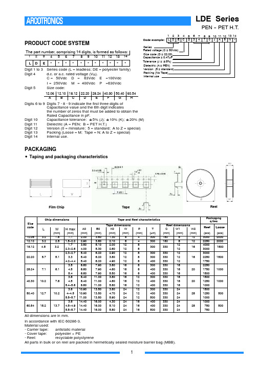
PACKAGING
S Taping and packaging characteristics
Film Chip
Tape
Reel
Packaging q.ties Reel dimensions W1 W2 ∅ (mm) (mm) (mm) 180 8 12 180 8 12 12 330 16 12 330 12 330 12 16 330 12 330 16 330 16 20 330 16 330 16 330 16 20 330 16 330 24 330 24 28 330 24 330 24 330 24 28 330 24 Reel (pcs) 3000 2250 4000 3000 3000 2250 1750 2250 1750 1500 1500 1250 1000 1500 1250 1000 1000 750 750 Loose (pcs) 2000 2000 1500 1500
Code example: 1 2 L D 3 4 E C 5 6 D 3 7 4 8 9 10 11 12 13 14 7 0 J A 5 N --
Digit 1 to 3 Series code (L = leadless; DE = polyester family) Digit 4 d.c. or a.c. rated voltage (VR). C = 50Vdc D = 63Vdc E =100Vdc I = 250Vdc M = 400Vdc P =630Vdc Digit 5 Size code:
L
3.2 3.2 4.5 5.7
W
(mm) 1.6 2.5 3.2 5.1
H max
(mm) 1.1 1.5--2.0 1.7 2.3--2.6 2.3--2.7 3.3 4.2--4.4 3.5 4.5 5.4 3.6 4.5 5.4--5.6 3.6 4--4.5 5.5--5.7 3.6 4.5--4.9 5.5--5.7
[vip专享]IC-2820H新ICOM双段双显
![[vip专享]IC-2820H新ICOM双段双显](https://img.taocdn.com/s3/m/403352460b4e767f5acfceca.png)
IC-2820H
43m1m“-”5J2Gm001m244“92Zk-(1g2L)33-0”@6%0k3g-“1/”m7D%2BJ/Tg0d1Z-P318¬A-_2o"70X)c0?y2586zn”217 NE)
43m1m“-”5J2Gm001m244“92Zk-(1g2L)33-0”@6%0k3g-“1/”m7D%2BJ/Tg0d1Z-P318¬A-_2o"70X)c0?y2586zn”217 NE)
43m1m“-”J520Gm01m24“492k-Z(1)g2L3-”3060@k%3-g“/1”7mD2%BJ/Tg0d1-ZP318¬-A_2"o70)Xc0?y258z6n”217 NE)
ICOM 公司 IC2820 双段电台设备介绍
一、基本情况介绍 ICOM 公司于 2007 年初,推出了新款型的双段(U/V)车载式电台,设备型号为 IC-2820,与以往不同的是,该设备提供了基本形 态的 GPS(全球卫星定位系统)功能。 针对不同的销售地区,该电台目前分为三个版本,并以不同的后缀加以区别,即:IC-2820DG、IC2820G、IC2820H。 其中,IC-2820DG、IC2820G 两个版本为日本本国所使用,而 IC-2820H 则是针对其它国家或地区。IC-2820DG 与 IC-2820G 相比较 ,其功能、性能以及配置均相同,区别仅在于发射功率的大小,前者的最大发射功率为:50W,后者为:20W。 IC-2820H 的最大发射功率也为:50W,与 IC-2820DG 不同的地方是,在“V”段上的发射频率范围有所限制,前者是:144MHz~1 48 MHz,后者是:144MHz~146 MHz。
xh
43m1m“-”5J2Gm001m244“92Zk-(1g2L)33-0”@6%0k3g-“1/”m7D%2BJ/Tg0d1Z-P318¬A-_2o"70X)c0?y2586zn”217 NE)
ECI2820控制器硬件手册

ECI2820网络控制卡硬件手册Version 1.0版权说明本手册版权归深圳市正运动技术有限公司所有,未经正运动公司书面许可,任何人不得翻印、翻译和抄袭本手册中的任何内容。
涉及ECI控制器软件的详细资料以及每个指令的介绍和例程,请参阅ZBASIC软件手册。
本手册中的信息资料仅供参考。
由于改进设计和功能等原因,正运动公司保留对本资料的最终解释权!内容如有更改,恕不另行通知!调试机器要注意安全!请务必在机器中设计有效的安全保护装置,并在软件中加入出错处理程序,否则所造成的损失,正运动公司没有义务或责任对此负责。
目录ECI2820网络控制卡硬件手册 (1)第一章控制卡简介 (1)1.1连接配置 (1)1.2安装和编程 (2)1.3产品特点 (2)第二章硬件描述 (3)2.1ECI2820型号规格 (3)2.1.1订货信息: (3)2.2ECI2820接线 (4)2.2.1电源/CAN接口信号: (5)2.2.2RS232接口信号: (5)2.2.3以太网接口信号: (6)2.2.4模拟量输入输出信号: (6)2.2.5通用输入信号: (6)2.2.6输入0-7: (7)2.2.7输入8-15: (7)2.2.8输入16-23: (7)2.2.9输出0-7: (8)2.2.10输出8-15: (9)2.2.11手轮接口信号: (9)2.2.12轴接口信号: (11)2.2.13轴接线参考: (12)2.2.13.1低速差分脉冲口接线参考 (12)2.2.13.2高速差分脉冲口接线参考 (14)2.2.13.3编码器接线参考 (16)第三章扩展模块 (16)3.1扩展模块CAN总线、输入输出、电源接线参考: (16)第四章常见问题 (16)第五章硬件安装 (17)5.1ECI2820安装 (18)第一章控制卡简介ECI是正运动技术推出的网络运动控制卡型号简称。
ECI2820系列控制卡支持最多达12轴直线插补、任意圆弧插补、空间圆弧、螺旋插补、电子凸轮、电子齿轮、同步跟随、虚拟轴、机械手指令等;采用优化的网络通讯协议可以实现实时的运动控制。
上海海栎创微电子有限公司 HAA2820 数据手册说明书

上海海栎创微电子有限公司HAA2820数据手册5W单声道、带有AGC防破音功能、AB/D切换、自适应电荷泵升压、自适应MUTE功能的音频功率放大器Rev:V1.02018/03/01HAA2820数据手册1.概述HAA2820是一款内置电荷泵升压的D类音频功率放大器,在4.2V电源电压的情况下,可以为4Ω负载送出5W(THD+N=10%)的输出功率。
HAA2820内置AGC模式,当输入信号较高的时候,可以自动降低内部增益,防止输出发生截顶失真,提升大音量播放音乐时的音质。
HAA2820带有OT,OC,OVP,UVLO等保护功能,有效保护芯片。
2.芯片特点◆最大输出功率: 5.06W (4.2V,4Ω,10%THD+N);4.2W (4.2V,4Ω,1%THD+N)◆AGC Function◆AB、D function◆底噪:47uVrms(Gain=16V/V, Class D);30uVrms(Gain=12V/V, Class AB)◆THD+N:0.005%◆效率: 71%(3.6V, 4Ω,2W)◆自适应MUTE功能◆自适应电荷泵升压功能◆UVLO,OTP,OCP◆eTSSOP-163.引脚分布/说明4.功能描述4.1 Ctrl<2:1> ControlHAA2820有四种工作状态,通过Ctrl<2:1>两个控制管脚进行控制,如下图所示。
00时芯片关断,关断电流小于1uA。
01的时候为D类工作模式,同时AGC功能开启,当输出将要出现截顶失真的时候,主动降低内部增益,使输出保持非截顶失真的状态,提高音质,有效保护喇叭。
10的时候为D类工作模式,AGC功能关闭。
11的时候为AB类工作模式,同时电荷泵不升压,处于直通模式,消除芯片对FM信号的EMI影响。
模式切换的时候需要先将Ctrl<1:0>置为00,将芯片关闭复位,再进入需要的工作模式,以防止出现异常的切换杂音。
LDEIxxxx中文资料
PACKAGING
S Taping and packaging characteristics
Film Chip
Tape
Reel
Packaging q.ties Reel dimensions W1 W2 ∅ (mm) (mm) (mm) 180 8 12 180 8 12 12 330 16 12 330 12 330 12 16 330 12 330 16 330 16 20 330 16 330 16 330 16 20 330 16 330 24 330 24 28 330 24 330 24 330 24 28 330 24 Reel (pcs) 3000 2250 4000 3000 3000 2250 1750 2250 1750 1500 1500 1250 1000 1500 1250 1000 1000 750 750 Loose (pcs) 2000 2000 1500 1500
28.24
7.1
6.1
1000
40.30
10.2
7.6
1000
50.40
12.7
10.2
500
60.54
15.2
13.7
500
All dimensions are in mm. In accordance with IEC 60286-3. Material used: - Carrier tape: antistatic material - Cover tape: polyester + PE - Reel: recyclable polystyrene All parts in bulk or on reel are packed in hermetically sealed moisture barrier bag (MBB).
ATR2820中文资料
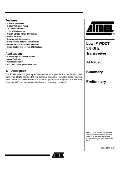
Features Array• 5.8 GHz Transceiver•5dBm TX Output Power•–97 dBm Sensitivity•1152 kBit/s Data-rate•Supply-voltage Range 2.9V to 3.6V•Low IF Receiver•Low Current Consumption•Few Low Cost External Components•No Mechanical Adjustment Required•Small 32 pin 5mm×5mm QFN PackageApplications• 5.8GHz Digital Cordless Phones•Game Controllers•Wireless Head Set•FCC Part 15 Compliant Radio Link1.DescriptionThe ATR2820 is a single-chip RF-transceiver for applications in the 5.8GHz ISM band. The QFN32 packaged IC is a complete transceiver including image rejection mixer, low-IF filter, FM demodulator, RSSI, TX preamplifier, integrated PLL with fullyintegrated VCO. No mechanical adjustment is necessary in production.24704AS–DECT–04/07ATR2820[Preliminary]Figure 1-1.Block Diagram34704AS–DECT–04/07ATR2820[Preliminary]3.Package Information2.Ordering InformationExtended Type Number PackageRemarks A TR2820-PNQGQFN32,5mm ×5mmTaped and reeledDisclaimer: The information in this document is provided in connection with Atmel products. No license, express or implied, by estoppel or otherwise,to any intellectual property right is granted by this document or in connection with the sale of Atmel products. EXCEPT AS SET FORTH IN ATMEL ’S TERMS AND CONDI-TIONS OF SALE LOCATED ON ATMEL ’S WEB SITE, ATMEL ASSUMES NO LIABILITY WHATSOEVER AND DISCLAIMS ANY EXPRESS, IMPLIED OR STATUTORY WARRANTY RELATING TO ITS PRODUCTS INCLUDING, BUT NOT LIMITED TO, THE IMPLIED WARRANTY OF MERCHANTABILITY, FITNESS FOR A PARTICULAR PURPOSE, OR NON-INFRINGEMENT. IN NO EVENT SHALL ATMEL BE LIABLE FOR ANY DIRECT, INDIRECT, CONSEQUENTIAL, PUNITIVE, SPECIAL OR INCIDEN-TAL DAMAGES (INCLUDING, WITHOUT LIMITATION, DAMAGES FOR LOSS OF PROFITS, BUSINESS INTERRUPTION, OR LOSS OF INFORMATION) ARISING OUT OF THE USE OR INABILITY TO USE THIS DOCUMENT, EVEN IF ATMEL HAS BEEN ADVISED OF THE POSSIBILITY OF SUCH DAMAGES. Atmel makes no representations or warranties with respect to the accuracy or completeness of the contents of this document and reserves the right to make changes to specifications and product descriptions at any time without notice. Atmel does not make any commitment to update the information contained herein. Unless specifically provided otherwise, Atmel products are not suitable for, and shall not be used in, automotive applications. Atmel’s products are not intended, authorized, or warranted for use as components in applications intended to support or sustain life.Atmel CorporationAtmel Operations2325 Orchard Parkway San Jose, CA 95131, USA Tel: 1(408) 441-0311Fax: 1(408) 487-2600Regional HeadquartersEuropeAtmel SarlRoute des Arsenaux 41Case Postale 80CH-1705 Fribourg SwitzerlandTel: (41) 26-426-5555Fax: (41) 26-426-5500AsiaRoom 1219Chinachem Golden Plaza 77 Mody Road Tsimshatsui East Kowloon Hong KongTel: (852) 2721-9778Fax: (852) 2722-1369Japan9F, Tonetsu Shinkawa Bldg.1-24-8 ShinkawaChuo-ku, Tokyo 104-0033JapanTel: (81) 3-3523-3551Fax: (81) 3-3523-7581Memory2325 Orchard Parkway San Jose, CA 95131, USA Tel: 1(408) 441-0311Fax: 1(408) 436-4314Microcontrollers2325 Orchard Parkway San Jose, CA 95131, USA Tel: 1(408) 441-0311Fax: 1(408) 436-4314La Chantrerie BP 7060244306 Nantes Cedex 3, France Tel: (33) 2-40-18-18-18Fax: (33) 2-40-18-19-60ASIC/ASSP/Smart CardsZone Industrielle13106 Rousset Cedex, France Tel: (33) 4-42-53-60-00Fax: (33) 4-42-53-60-011150 East Cheyenne Mtn. Blvd.Colorado Springs, CO 80906, USA Tel: 1(719) 576-3300Fax: 1(719) 540-1759Scottish Enterprise Technology Park Maxwell BuildingEast Kilbride G75 0QR, Scotland Tel: (44) 1355-803-000Fax: (44) 1355-242-743RF/AutomotiveTheresienstrasse 2Postfach 353574025 Heilbronn, Germany Tel: (49) 71-31-67-0Fax: (49) 71-31-67-23401150 East Cheyenne Mtn. Blvd.Colorado Springs, CO 80906, USA Tel: 1(719) 576-3300Fax: 1(719) 540-1759BiometricsAvenue de Rochepleine BP 12338521 Saint-Egreve Cedex, France Tel: (33) 4-76-58-47-50Fax: (33) 4-76-58-47-60Literature Requests/literature4704AS–DECT–04/07© 2007 Atmel Corporation . All rights reserved. Atmel ®, logo and combinations thereof, and others, are registered trademarks or trademarks of Atmel Corporation or its subsidiaries. Other terms and product names may be trademarks of others.。
- 1、下载文档前请自行甄别文档内容的完整性,平台不提供额外的编辑、内容补充、找答案等附加服务。
- 2、"仅部分预览"的文档,不可在线预览部分如存在完整性等问题,可反馈申请退款(可完整预览的文档不适用该条件!)。
- 3、如文档侵犯您的权益,请联系客服反馈,我们会尽快为您处理(人工客服工作时间:9:00-18:30)。
PACKAGING
S Taping and packaging characteristicPackaging q.ties Reel dimensions W1 W2 ∅ (mm) (mm) (mm) 180 8 12 180 8 12 12 330 16 12 330 12 330 12 16 330 12 330 16 330 16 20 330 16 330 16 330 16 20 330 16 330 24 330 24 28 330 24 330 24 330 24 28 330 24 Reel (pcs) 3000 2250 4000 3000 3000 2250 1750 2250 1750 1500 1500 1250 1000 1500 1250 1000 1000 750 750 Loose (pcs) 2000 2000 1500 1500
Code example: 1 2 L D 3 4 E C 5 6 D 3 7 4 8 9 10 11 12 13 14 7 0 J A 5 N --
Digit 1 to 3 Series code (L = leadless; DE = polyester family) Digit 4 d.c. or a.c. rated voltage (VR). C = 50Vdc D = 63Vdc E =100Vdc I = 250Vdc M = 400Vdc P =630Vdc Digit 5 Size code:
L
3.2 3.2 4.5 5.7
W
(mm) 1.6 2.5 3.2 5.1
H max
(mm) 1.1 1.5--2.0 1.7 2.3--2.6 2.3--2.7 3.3 4.2--4.4 3.5 4.5 5.4 3.6 4.5 5.4--5.6 3.6 4--4.5 5.5--5.7 3.6 4.5--4.9 5.5--5.7
1
元器件交易网
LDE Series
PEN -- PET H.T. CAPACITANCE AND VOLTAGE RANGE
STANDARD VERSION
Size table
Rated Cap. 1000 pF 1200 pF 1500 pF 1800 pF 2200 pF 2700 pF 3300 pF 3900 pF 4700 pF 5600 pF 6800 pF 8200 pF 0.010 μF 0.012 μF 0.015 μF 0.018 μF 0.022 μF 0.027 μF 0.033 μF 0.039 μF 0.047 μF 0.056 μF 0.068 μF 0.082 μF 0.10 μF 0.12 μF 0.15 μF 0.18 μF 0.22 μF 0.27 μF 0.33 μF 0.39 μF 0.47 μF 0.56 μF 0.68 μF 0.82 μF 1.0 μF 1.2 μF 1.5 μF 1.8 μF 2.2 μF 2.7 μF 3.3 μF 3.9 μF 4.7 μF
Chip dimensions Size code 12.06 12.10 18.12 22.20
Tape and Reel characteristics A0 (mm) 2.00 2.90 3.50 4.00 5.40 5.40 5.40 6.60 6.60 6.60 8.40 8.40 8.60 10.90 10.90 11.00 14.40 14.40 14.40 B0 (mm) 3.60 3.60 5.10 5.30 6.20 6.20 6.20 7.90 7.90 7.90 11.00 11.00 11.00 13.50 13.50 13.50 16.00 16.00 16.00 Tape dimensions K0 W (mm) (mm) 1.30 8 2.10 8 2.00 12 2.60 12 2.90 12 3.80 12 4.90 12 3.80 16 4.60 16 5.50 16 3.80 16 4.60 16 5.80 16 3.80 24 4.70 24 5.90 24 4.30 24 5.10 24 5.80 24 P (mm) 4 4 8 8 8 8 8 8 8 8 12 12 12 12 12 12 16 16 16 T (μm) 300 300 300 300 300 400 300 400 400 300 400 400 300 400 500 400 400 500
63Vdc/40Vac
Part Number LDEDC1100 - -5- LDEDC1120 - -5- LDEDC1150 - -5- LDEDC1180 - -5- LDEDC1220 - -5- LDEDC1270 - -5- LDEDC1330 - -5- LDEDC1390 - -5- LDEDC1470 - -5- LDEDC1560 - -5- LDEDC1680 - -5- LDEDC1820 - -5- LDEDC2100 - -5- LDEDC2120 - -5- LDEDC2150 - -5- LDEDC2180 - -5- LDEDC2220 - -5- LDEDC2270 - -5- LDEDC2330 - -5- LDEDC2390 - -5- LDEDC2470 - -5- LDEDC2560 - -5- LDEDC2680 - -5- LDEDC2820 - -5- LDEDC3100 - -5- LDEDC3120 - -5- LDEDC3150 - -5- LDEDC3180 - -5- LDEDC3220 - -5- LDEDD3270 - -5- LDEDD3300 - -5- LDEDD3390 - -5- LDEDD3470 - -5- LDEDD3560 - -5- LDEDD3680 - -5- LDEDE3820 - -5- LDEDE4100 - -5- LDEDE4120 - -5- LDEDG4150- -5- LDEDG4180- -5- LDEDG4220- -5- LDEDG4270- -5- LDEDH4330 - -5- LDEDH4390 - -5- LDEDH4470 - -5- -
28.24
7.1
6.1
1000
40.30
10.2
7.6
1000
50.40
12.7
10.2
500
60.54
15.2
13.7
500
All dimensions are in mm. In accordance with IEC 60286-3. Material used: - Carrier tape: antistatic material - Cover tape: polyester + PE - Reel: recyclable polystyrene All parts in bulk or on reel are packed in hermetically sealed moisture barrier bag (MBB).
12.06 12.10 18.12 22.20 28.24 40.30 50.40 60.54 A B C D E F G H
Series Rated voltage (C = 50Vdc) Size code (D = 22.20) Capacitance = 0.47μF Tolerance (J = 5%) Dielectric (A = PEN) Version (5 = standard) Packing (N= Tape) Internal use
50Vdc/40Vac
size code 18.12 18.12 18.12 18.12 18.12 18.12 18.12 18.12 18.12 18.12 18.12 18.12 18.12 18.12 18.12 18.12 18.12 18.12 18.12 18.12 18.12 18.12 18.12 18.12 18.12 18.12 18.12 18.12 18.12 22.20 22.20 22.20 22.20 22.20 22.20 28.24 28.24 28.24 50.40 50.40 50.40 50.40 60.54 60.54 60.54 H max 1.7 1.7 1.7 1.7 1.7 1.7 1.7 1.7 1.7 1.7 1.7 1.7 1.7 1.7 1.7 1.7 1.7 1.7 1.7 1.7 2.3 2.3 2.3 2.3 2.3 1.7 1.7 2.3 2.3 2.3 2.3 2.3 2.3 3.3 3.3 3.5 3.5 3.5 3.6 3.6 3.6 4.5 4.5 4.5 4.9 Part Number LDECC1100 - -5- LDECC1120 - -5- LDECC1150 - -5- LDECC1180 - -5- LDECC1220 - -5- LDECC1270 - -5- LDECC1330 - -5- LDECC1390 - -5- LDECC1470 - -5- LDECC1560 - -5- LDECC1680 - -5- LDECC1820 - -5- LDECC2100 - -5- LDECC2120 - -5- LDECC2150 - -5- LDECC2180 - -5- LDECC2220 - -5- LDECC2270 - -5- LDECC2330 - -5- LDECC2390 - -5- LDECC2470 - -5- LDECC2560 - -5- LDECC2680 - -5- LDECC2820 - -5- LDECC3100 - -5- LDECC3120 - -5- LDECC3150 - -5- LDECC3180 - -5- LDECC3220 - -5- LDECD3270 - -5- LDECD3300 - -5- LDECD3390 - -5- LDECD3470 - -5- LDECD3560 - -5- LDECD3680 - -5- LDECE3820 - -5- LDECE4100 - -5- LDECE4120 - -5- LDECG4150- -5- LDECG4180- -5- LDECG4220- -5- LDECG4270- -5- LDECH4330 - -5- LDECH4390 - -5- LDECH4470 - -5- -
