PC7951CC3-12CD中文资料
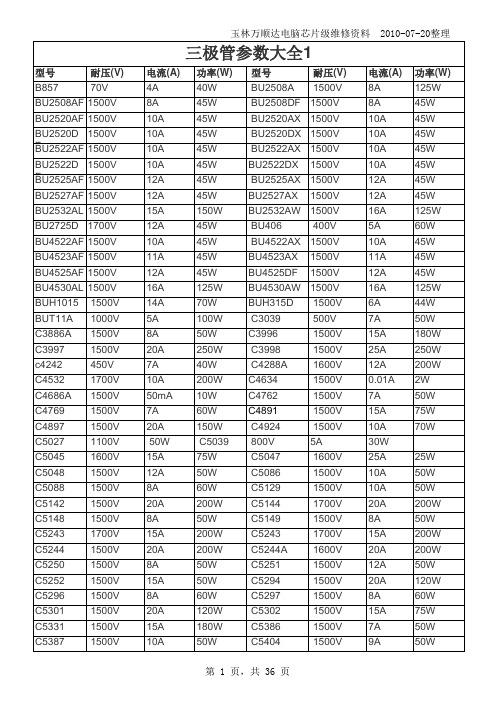
常用三极管参数大全
玉林万顺达电脑芯片级维修资料 2010-07-20整理玉林万顺达电脑芯片级维修资料 2010-07-20整理玉林万顺达电脑芯片级维修资料 2010-07-20整理玉林万顺达电脑芯片级维修资料 2010-07-20整理玉林万顺达电脑芯片级维修资料 2010-07-20整理玉林万顺达电脑芯片级维修资料 2010-07-20整理玉林万顺达电脑芯片级维修资料 2010-07-20整理玉林万顺达电脑芯片级维修资料 2010-07-20整理玉林万顺达电脑芯片级维修资料 2010-07-20整理玉林万顺达电脑芯片级维修资料 2010-07-20整理玉林万顺达电脑芯片级维修资料 2010-07-20整理玉林万顺达电脑芯片级维修资料 2010-07-20整理玉林万顺达电脑芯片级维修资料 2010-07-20整理玉林万顺达电脑芯片级维修资料 2010-07-20整理玉林万顺达电脑芯片级维修资料 2010-07-20整理玉林万顺达电脑芯片级维修资料 2010-07-20整理玉林万顺达电脑芯片级维修资料 2010-07-20整理玉林万顺达电脑芯片级维修资料 2010-07-20整理玉林万顺达电脑芯片级维修资料 2010-07-20整理玉林万顺达电脑芯片级维修资料 2010-07-20整理玉林万顺达电脑芯片级维修资料 2010-07-20整理玉林万顺达电脑芯片级维修资料 2010-07-20整理玉林万顺达电脑芯片级维修资料 2010-07-20整理玉林万顺达电脑芯片级维修资料 2010-07-20整理玉林万顺达电脑芯片级维修资料 2010-07-20整理玉林万顺达电脑芯片级维修资料 2010-07-20整理玉林万顺达电脑芯片级维修资料 2010-07-20整理玉林万顺达电脑芯片级维修资料 2010-07-20整理玉林万顺达电脑芯片级维修资料 2010-07-20整理玉林万顺达电脑芯片级维修资料 2010-07-20整理。
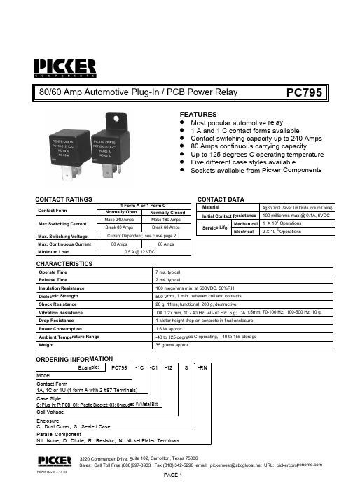
PC7951CC3-12C中文资料
.300 (7.6)
30
.150 (3.8)
Holes for Pins 30, 87 & 87a are 3 X .087 (2.2) by .063 (1.6) Pins 85 & 86 are .079 (2.0) by .047 (1.2)
Notes:
Tolerances + .010 unless otherwise noted Maximum make current refers to inrush of a lamp load In 85 degree C ambient reduce maximum coil voltage to 72%
Plug-In Case (C) and PCB Case (P)
.453 (11.5)
.665 (16.9)
PC795
Continuous Voltage Max.
(VDC) 10.1 20.5 39.1
Bottom View
.665 (16.9)
.250 (6.3)
.374 (9.5)
.709 (18.0)
Initial Contact Resistance Mechanical
Service Life Electrical
100 milliohms max @ 0.1A, 6VDC 1 X 10⁷ Operations 2 X 10 5 Operations
CHARACTERISTICS
Operate Time Release Time Insulation Resistance Dielectric Strength Shock Resistance Vibration Resistance Drop Resistance Power Consumption Ambient Temperature Range Weight
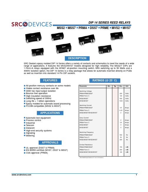
PRMA1C05中文资料
-
108
1010
-
Ω
-
1.5
2
-
1.2
2
pF
3
4
-
3
4
pF
1400
-
-
2000
-
- VDC/Peak AC
I/O
1400
-
-
5600
-
- VDC/Peak AC
TOP
-
1.2
1.75
-
1.2
1.75
ms
TREL
-
1
1.50
-
1
1.50
ms
TA
-40
-
+105 -40
-
+105
°C
TO
-38
-
+75
-38
Carry Current PRMA/PRME/DSS7 PRMA Form C MSS2/MSS7 MVS2/MVS7
Switching Frequency PRMA/PRME/DSS7 PRMA Form C MSS2/MSS7/MVS2/MVS7
Contact Resistance PRMA/PRME/DSS7 PRMA Form C MSS2/MSS7/MVS2/MVS7
11±1ms, 1/2 Sine Wave
(1) Refer to life graphs
SYMBOL
MSS2 Molded 8 Pin All position Wetted contacts
MIN TYP MAX
MSS7 Molded 4 Pin All position Wetted contacts
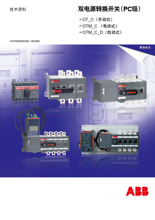
双电源转换开关-PC级
PC400-8, PC400LC-8, PC450-8, PC450LC-8 Shop 说明书

SEN02223-15-8-8-8-870001700017000170001e p c a t al o g s .c ome p c a t a l o g s .c o mPC400, 450-81SEN02225-15HYDRAULIC EXCAVATORPC400-8PC400LC-8PC450-8PC450LC-8Machine model Serial numberPC400-870001 and up PC400LC-870001 and up PC450-870001 and up PC450LC-870001 and up00 Index and forewordIndexComposition of shop manual ..........................................................................................................................2Table of contents (4)e pc at al o g s .c omSEN02225-1500 Index and foreword2PC400, 450-8Composition of shop manualThe contents of this shop manual are shown together with Form No. in a list.Note 1:Always keep the latest version of this manual in accordance with this list and utilize accordingly.The marks shown to the right of Form No. denote the following:Q : New issue (to be filed additionally)q : Revision (to be replaced for each Form No.)Note 2:This shop manual can be supplied for each Form No.Note 3:To file this shop manual in the special binder for management, handle it as follows:•Place a divider on the top of each section in the file after matching the Tub No. with No. indicated next to each Section Name shown in the table below:•File overview and other materials in sections in the order shown below and utilize them accord-ingly.Section TitleForm NumberShop Manual, contents binder, binder label and tabs SEN02223-1500 Index and foreword SEN02224-15IndexSEN02225-15q Foreword and general information SEN02226-0201 SpecificationSEN02227-02Specification and technical dataSEN02228-0210 Structure, function and maintenance standard SEN02229-08Engine and cooling system SEN02230-00Power trainSEN02231-00Undercarriage and frame SEN02232-00Hydraulic system, Part 1SEN02233-00Hydraulic system, Part 2SEN02234-04 Hydraulic system, Part 3SEN02235-02q Work equipmentSEN02236-00Cab and its attachments SEN02237-00Electrical system SEN02238-0320 Standard value tableSEN02239-03Standard service value table SEN02643-0330 Testing and adjustingSEN02240-07Testing and adjusting, Part 1SEN02644-04Testing and adjusting, Part 2SEN02645-06Testing and adjusting, Part 3SEN02662-0240 TroubleshootingSEN02241-04Failure code table and fuse locations SEN02646-03General information on troubleshootingSEN02647-03Troubleshooting by failure code (Display of code), Part 1SEN02648-04Troubleshooting by failure code (Display of code), Part 2SEN02649-03Troubleshooting by failure code (Display of code), Part 3SEN02650-04Troubleshooting of electrical system (E-mode)SEN02651-03Troubleshooting of hydraulic and mechanical system (H-mode)SEN02652-03e pc at al o g s .c om00 Index and foreword SEN02225-15PC400, 450-83Troubleshooting of engine (S-mode)SEN02653-0250 Disassembly and assemblySEN02242-07General information on disassembly and assembly SEN02654-03Engine and cooling system SEN02655-01Power trainSEN02656-02Undercarriage and frame SEN02657-04Hydraulic system SEN02658-01Work equipmentSEN02659-01q Cab and its attachments SEN02660-01Electrical system SEN02661-0290 Diagrams and drawingsSEN02243-04Hydraulic diagrams and drawings SEN02244-01q Electrical diagrams and drawingsSEN02245-03e pc at al o g s .c omBuy nowKomatsu Hydraulic Excavator PC400 -8, PC400LC-8, PC450 -8, PC450LC-8 Shop Manual PDFWith Instant Download。
CC0201CRNPO9BN2R7中文资料

物料编号:CC0201CRNPO9BN2R7细参数_易容网
MLCC即是多层陶瓷电容片式,是电子信息产品不可或缺的基本组件之一。
我国MLCC的生产起步在80年代初,行业早期主要是在外资企业的带动下发展起来的,近年来国内企业在技术上实现突破,行业国产化成效显著,并推动了MLCC产量迅速增长。
目前,MLCC的应用领域已从手机、电脑、电视机等消费电子领域,逐步拓展到新能源发电、新能源汽车、节能灯具、轨道交通、直流输变电、三网融合、高清电视、机顶盒、手机电视等多个行业。
对于这个悄悄活跃在人们生活中的元件你又知道多少呢.
本次易容网为大家推荐比较常用的MLCC村田 | Murata品牌的料号CC0201CRNPO9BN2R7的相关参数
易容网是深圳市易容信息技术有限公司独自研发的全球最大的MLCC搜索采购服务网站,2014年创立于深圳市南山区,全国首家电子元器件行业电容元件的搜索引擎及o2o商务服务平台。
易容网()现已建成全球最大的MLCC电容搜索引擎数据库,包含全球25家电容生产厂商超过28万组MLCC产品数据,用户可根据行业应用、物料编号、规格参数等信息快速的找到所有相关的MLCC电容数据。
易容网在搜索服务的前提下还提供村田、TDK、国巨、太阳诱电、风华高科等常见品牌产品的o2o商务服务,让企业客户实现询价、报价、在线订单、出库、实时物流、签收、账期服务等在线一站式商务服务体验。
ADS7952中文资料
MODEL ADS7953 SB ADS7952 SB ADS7951 SB ADS7950 SB ADS7953 S ADS7952 S ADS7951S ADS7950 S
ORDERING INFORMATION - 12-BIT
MAXIMUM INTEGRAL LINEARITY
(LSB)
MAXIMUM DIFFERENTIAL
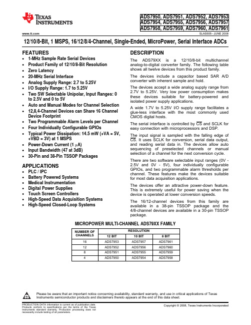
The input signal is sampled with the falling edge of CS. It uses SCLK for conversion, serial data output, and reading serial data in. The devices allow auto sequencing of preselected channels or manual selection of a channel for the next conversion cycle.
+VBD = 3V) at 1 MSPS • Power-Down Current (1 µA) • Input Bandwidth (47 at 3dB) • 30-Pin and 38-Pin TSSOP Packages
APPLICATIONS
• PLC / IPC • Battery Powered Systems • Medical Instrumentation • Digital Power Supplies • Touch Screen Controllers • High-Speed Data Acquisition Systems • High-Speed Closed-Loop Systems
8 BIT ADS7961 ADS7960 ADS7959 ADS7958
CDE-121C 说明书

ALPINE ELECTRONICS MARKETING, INC.1-1-8 Nishi Gotanda,Shinagawa-ku,Tokyo 141-0031, JapanPhone 03-5496-8231ALPINE ELECTRONICS OF AMERICA, INC.19145 Gramercy Place, Torrance,California 90501, U.S.A.Phone 1-800-ALPINE-1 (1-800-257-4631)ALPINE ELECTRONICS OF CANADA, INC.777 Supertest Road, Toronto,Ontario M3J 2M9, CanadaPhone 1-800-ALPINE-1 (1-800-257-4631)ALPINE ELECTRONICS OF AUSTRALIA PTY. LTD.161-165 Princes Highway, Hallam Victoria 3803, Australia Phone 03-8787-1200ALPINE ELECTRONICS GmbH Wilhelm-Wagenfeld-Str. 1-3, 80807 München, Germany Phone 089-32 42 640ALPINE ELECTRONICS OF U.K. LTD.Alpine House Fletchamstead Highway, Coventry CV4 9TW, U.K.Phone 0870-33 33 763ALPINE ELECTRONICS FRANCE S.A.R.L.(RCS PONTOISE B 338 101 280)98, Rue de la Belle Etoile, Z.I. Paris Nord Il,B.P . 50016, 95945 Roissy Charles de GaulleCedex, France Phone 01-48638989ALPINE ITALIA S.p.A.Viale C. Colombo 8, 20090 Trezzano Sul Naviglio (MI), Italy Phone 02-484781ALPINE ELECTRONICS DE ESPAA, S.A.Portal de Gamarra 36, Pabelln, 3201013 Vitoria (Alava)-APDO 133, Spain Phone 945-283588ALPINE ELECTRONICS (BENELUX) GmbH Leuvensesteenweg 510-B6,1930 Zaventem, Belgium Phone 02-725-13 15••用戶手冊請在使用本設備之前先閱讀用戶手冊。
PC3SD12NTZ系列光学接触器说明书

PC3SD12NTZ Series■ FeaturesV DRM : 600V, Cost effective Non-zero cross type DIP 6pinPhototriac Coupler for triggering1. High repetitive peak off-state voltage (V DRM : 600V)2. Non-zero crossing functionality3. 6 pin DIP package4. Superior noise immunity (dV/dt : MIN. 1 000V/µs)5. Double transfer mold construction (Ideal for Flow Soldering)6. High isolation voltage between input and output (V iso (rms) : 5.0kV)■ DescriptionPC3SD12NTZ Series Phototriac Coupler include an infrared emitting diode (IRED) optically coupled to an output Phototriac.These devices feature full wave control and are ideal isolated drivers for medium to high current Triacs.DIP package provides 5.0kV isolation from input to output with superior commutative noise immunity.Notice The content of data sheet is subject to change without prior notice.In the absence of confirmation by device specification sheets, SHARP takes no responsibility for any defects that may occur in equipment using any SHARP ■ Agency approvals/Compliance1. Triggering for Triacs used to switch on and off devices which require AC Loads.For example heaters, fans, motors, solenoids, and valves.2. Triggering for Triacs used for implementing phase control in applications such as lighting control and temperature control (HVAC).3. AC line control in power supply applications.■Applications1.Recognized by UL1577 (Double protection isolation), file No. E64380 (as model No. 3SD12)2. Approved by CSA, file No. CA95323 (as model No. 3SD12)3. Optionary available VDE Approved (∗)(DIN EN 60747-5-2), file No. 40008189 (as model No. 3SD12)4. Package resin : UL flammability grade (94V-0)(∗)DIN EN60747-5-2 : successor standard of DIN VDE0884. Up to Date code "RD" (December 2003), approval of DIN VDE0884.From Date code "S1" (January 2004), approval of DIN EN60747-5-2.(∗∗)Reinforced insulation type is also available. (PC3SF11YVZ Series )■Internal Connection DiagramAnode Cathode NCAnode/CathodeNo external connection Cathode/Anode■ Outline Dimensions(Unit : mm)■ Outline Dimensions∗(Unit : mm)Date code (2 digit)Rank markRefer to the Model Line-up tableA.D.199019911992199319941995199619971998199920002001MarkABCDEFHJKLMN Mark P R S T U V W X A B C Mark 123456789O N DMonth January February March April May June July August September October November December A.D 20022003200420052006200720082009201020112012······2nd digitMonth of production 1st digitYear of productionFactory identification markPlease contact the local SHARP sales representative to see the actural status of the production.repeats in a 20 year cycle■ Electro-optical CharacteristicsParameterSymbol Unit InputOutput(T a =25˚C)Forward voltageReverse currentRepentitive peak OFF-state current ON-state voltageHolding currentCritical rate of rise of OFF-state voltageMinimum trigger currentIsolation resistance Turn-on timeV F I R I DRM V T I H dV/dt I FT R ISO t onV µA µA V mA V/µs mA ΩµsI F =20mA V R =3V V D =V DRM I T =0.1A V D =6V V D =1/√−2 ·V DRM V D =6V, R L =100ΩDC500V,40 to 60%RH V D =6V, R L =100Ω, I F =20mAConditions −−−−0.11 000−5×10¹⁰− 1.2−−−−2 000−1011−1.41012.53.5−10−50MIN.TYP.MAX.Transfer charac-teristics Rank A ■ Absolute Maximum RatingsSymbol Rating Unit(T a =25˚C)*2*1I F V R I T (rms)I surge V DRMV iso (rms)T opr T stg T sol mA V A AV kV ˚C ˚C ˚C *3*45060.11.26005.0−30 to +100−55 to +125270*1 40 to 60%RH, AC for 1minute, f =60Hz*2 For 10s*3 f =50Hz sine wave*4 Lead solder plating models: 260˚CForward currentReverse voltageRMS ON-state currentPeak one cycle surge current Repetitive peak OFF-state voltage Isolation voltageOperating temperatureStorage temperatureSoldering temperatureInputOutput Parameter Soldering areaLead Form Shipping PackageDINEN60747-5-2 Model No.Through-Hole-MAX.10Sleeve50pcs/sleeveApprovedSMT Gullwing-ApprovedWide Through-Hole-PC3SD12NTZAFApprovedAI FT[mA](V D=6V,R L=100Ω)Rank markModel Line-upLead Form Shipping PackageDINEN60747-5-2 Model No.Wide SMT Gullwing-MAX.10Taping1 000pcs/reelSleeve50pcs/sleeveApprovedSMT Gullwing-ApprovedWide SMT Gullwing-ApprovedAI FT[mA](V D=6V,R L=100Ω)Rank markPC3SD12NWZAFPC3SD12YVZAFPC3SD12NVZAFPC3SD12YXZAFPC3SD12NXZAFPC3SD12YTZAFPC3SD12YWPAFPC3SD12NWPAFPC3SD12YXPAFPC3SD12NXPAFPC3SD12YWZAFPlease contact a local SHARP sales representative to inquire about production status.F o r w a r d c u r r e n t I F (m A )Ambient temperature T a (°C)010203040506070−3010050Fig.1 Forward Current vs. AmbientTemperatureFig.2 RMS ON-state Current vs.Ambient TemperatureR M S O N -s t a t e c u r r e n t I T (r m s ) (m A )0255075100125150175−3010050Ambient temperature T a (°C)F o r w a r d c u r r e n t I F (m A )Forward voltage V F (V)151050100Fig.3 Forward Current vs. Forward VoltageFig.4 Minimum Trigger Current vs.Ambient Temperature012345678910M i n i m u m t r i g g e r c u r r e n t I F T (m A )Ambient temperature T a (°C)Fig.6 ON-state Voltage vs.Ambient TemperatureO N -s t a t e v o l t a g e V T (V )121.81.61.41.2Ambient temperature T a (°C)1.91.71.51.31.1Fig.5 Relative Repetitive Peak OFF-stateVoltage vs. Ambient TemperatureR e l a t i v e r e p e t i t i v e p e a k O F F -s t a t e v o l t a g e V D R M (T j =T a ) / V D R M (T j =25°C )0.71.31.21.110.90.8−40−20020406080100Ambient temperature T a (°C)Fig.9 Turn-on Time vs. Forward CurrentR e p e t i t i v e p e a k O F F -s t a t e c u r r e n t I D R M (A )10−1010−810−610−910−7Ambient temperature T a (°C)Remarks : Please be aware that all data in the graph are just for reference.Fig.8 Repetitive Peak OFF-state Current vs.Ambient TemperatureT u r n -o n t i m e t o n (µs )101001 000Forward current I F (mA)Fig.7 Holding Current vs.Ambient TemperatureH o l d i n g c u r r e n t I H (m A)0.1110Ambient temperature T a (°C)● Recommended Foot Print (reference)SMT Gullwing Lead-formWide SMT Gullwing Lead-form(Unit : mm)■ Design Considerations In order for the Phototriac to turn off, the triggering current (I F ) must be 0.1mA or less.Please refrain from using these devices in a direct drive configuration.These Phototriac Coupler are intended to be used as triggering device for main Triacs.Please ensure that the output rating of these devices will be sufficient for triggering the main output Triac of your choice. Failure to do may result in malfunctions.In phase control applications or where the Phototriac Coupler is being by a pulse signal, please ensure that the pulse width is a minimum of 1ms.For designs that will experience excessive noise or sudden changes in load voltage, please include an appropriate snubber circuit as shown in the below circuit.Please keep in mind that Sharp Phototriac Couplers incorporate superor dV/dt ratings which can often eliminate the need for a snubber circuit.● DegradationIn general, the emission of the IRED used in Phototriac Couplers will degrade over time.In the case where long term operation and / or constant extreme temperature fluctuations will be applied to the devices, please allow for a worst case scenario of 50% degradation over 5years.Therefore in order to maintain proper operation, a design implementing these Phototriac Couplers should provide at least twice the minimum required triggering current from initial operation.● Design guide● Standard Circuit (Medium/High Power Triac Drive Circuit)Note) Please add the snubber circuit according to a condition.Any snubber or varistor used for the above mentioned scenarios should be locatedas close to the main output triac as possible.✩For additional design assistance, please review our corresponding Optoelectronic Application Notes.■ Manufacturing Guidelines Reflow Soldering:Reflow soldering should follow the temperature profile shown below.Soldering should not exceed the curve of temperature profile and time.Please don't solder more than twice.● Soldering Method Flow Soldering :Due to SHARP's double transfer mold construction submersion in flow solder bath is allowed under the below listed guidelines.Flow soldering should be completed below 270˚C and within 10s.Preheating is within the bounds of 100 to 150˚C and 30 to 80s.Please don't solder more than twice.Hand solderingHand soldering should be completed within 3s when the point of solder iron is below 400˚C.Please don't solder more than twice.Other noticesPlease test the soldering method in actual condition and make sure the soldering works fine, since the impact on the junction between the device and PCB varies depending on the tooling and soldering conditions.12343002001000(˚C)(min)● Cleaning instructionsSolvent cleaning :Solvent temperature should be 45˚C or below. Immersion time should be 3minutes or less.Ultrasonic cleaning :The impact on the device varies depending on the size of the cleaning bath, ultrasonic output, cleaning time, size of PCB and mounting method of the device.Therefore, please make sure the device withstands the ultrasonic cleaning in actual conditions in advance of mass production.Recommended solvent materials :Ethyl alcohol, Methyl alcohol and Isopropyl alcohol.In case the other type of solvent materials are intended to be used, please make sure they work fine in actual using conditions since some materials may erode the packaging resin.● Presence of ODCThis product shall not contain the following materials.And they are not used in the production process for this device.Regulation substances : CFCs, Halon, Carbon tetrachloride, 1.1.1-Trichloroethane (Methylchloroform)Specific brominated flame retardants such as the PBBOs and PBBs are not used in this product at all.■ Package specification● Sleeve package1. Through-Hole or SMT GullwingPackage materialsSleeve : HIPS (with anti-static material)Stopper : Styrene-ElastomerPackage methodMAX. 50pcs of products shall be packaged in a sleeve.Both ends shall be closed by tabbed and tabless stoppers.The product shall be arranged in the sleeve with its anode mark on the tabless stopper side.MAX. 20 sleeves in one case.Sleeve outline dimensions2. Wide Through-Hole or Wide SMT GullwingPackage materialsSleeve : HIPS (with anti-static material)Stopper : Styrene-ElastomerPackage methodMAX. 50pcs of products shall be packaged in a sleeve.Both ends shall be closed by tabbed and tabless stoppers.The product shall be arranged in the sleeve with its anode mark on the tabless stopper side.MAX. 20 sleeves in one case.Sleeve outline dimensionsSheet No.: D2-A07701F EN● Tape and Reel package 1. SMT Gullwing Package materialsCarrier tape : A-PET (with anti-static material) Cover tape : PET (three layer system)Reel : PSCarrier tape structure and DimensionsDimensions L ist(Unit:mm)A 16.0±0.3B 7.5±0.1C 1.75±0.1D 12.0±0.1E 2.0±0.1H 10.4±0.1I 0.4±0.05J 4.2±0.1K 7.8±0.1F 4.0±0.1G φ1.5+0.1−Dimensions L ist(Unit : mm)a 330b 17.5±1.5c 100±1.0d 13±0.5e 23±1.0f 2.0±0.5g 2.0±0.5Pull-out direction[Packing : 1 000pcs/reel]Reel structure and DimensionsDirection of product insertion2. Wide SMT GullwingPackage materialsCarrier tape : A-PET (with anti-static material) Cover tape : PET (three layer system)Reel : PSCarrier tape structure and DimensionsDimensions L istA 24.0±0.3B11.5±0.1C1.75±0.1D12.0±0.1E2.0±0.1H 12.2±0.1I0.4±0.05J4.15±0.1K7.6±0.1F4.0±0.1Gφ1.5+0.1−0(Unit : mm)Dimensions L ist(Unit : mm)a330b25.5±1.5c100±1.0d13±0.5e23±1.0f2.0±0.5g2.0±0.5Pull-out direction[Packing : 1 000pcs/reel] Reel structure and DimensionsDirection of product insertion· The circuit application examples in this publication are provided to explain representative applications of SHARP devices and are not intended to guarantee any circuit design or license any intellectual property rights. SHARP takes no responsibility for any problems rela-ted to any intellectual property right of a third party re-sulting from the use of SHARP's devices.· Contact SHARP in order to obtain the latest device specification sheets before using any SHARP device. SHARP reserves the right to make changes in the spec-ifications, characteristics, data, materials, structure, and other contents described herein at any time without notice in order to improve design or reliability. Manufac-turing locations are also subject to change without no-tice.· Observe the following points when using any devices in this publication. SHARP takes no responsibility for damage caused by improper use of the devices which does not meet the conditions and absolute maximum ratings to be used specified in the relevant specification sheet nor meet the following conditions:(i) The devices in this publication are designed for use in general electronic equipment designs such as:--- Personal computers--- Office automation equipment--- Telecommunication equipment [terminal]--- Test and measurement equipment --- Industrial control--- Audio visual equipment --- Consumer electronics(ii) Measures such as fail-safe function and redundant design should be taken to ensure reliability and safety when SHARP devices are used for or in connectionwith equipment that requires higher reliability such as:--- Transportation control and safety equipment (i.e.,aircraft, trains, automobiles, etc.)--- Traffic signals--- Gas leakage sensor breakers --- Alarm equipment--- Various safety devices, etc.(iii) SHARP devices shall not be used for or in connec-tion with equipment that requires an extremely high lev-el of reliability and safety such as:--- Space applications--- Telecommunication equipment [trunk lines]--- Nuclear power control equipment--- Medical and other life support equipment (e.g.,scuba).· If the SHARP devices listed in this publication fall with-in the scope of strategic products described in the For-eign Exchange and Foreign Trade Law of Japan, it is necessary to obtain approval to export such SHARP de-vices.· This publication is the proprietary product of SHARP and is copyrighted, with all rights reserved. Under the copyright laws, no part of this publication may be repro-duced or transmitted in any form or by any means, elec-tronic or mechanical, for any purpose, in whole or in part, without the express written permission of SHARP. Express written permission is also required before any use of this publication may be made by a third party.· Contact and consult with a SHARP representative if there are any questions about the contents of this pub-lication.■Important Notices。
AD7951 引脚功能中文说明(14Bit,1MSPS)
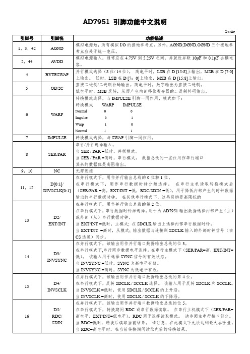
TEN
输入范围选择。根据以下情况与BIPOLAR配合使用:
输入范围
BIPOLAR
TEN
0V至5V
0
0
0V至10V
0
1
±5V
1
0
±10V
1
1
31
RD
读取数据。当CS和RD均为低电平时,使能接口并行或串行输出总线。
32
CS
芯片选择。当CS和RD均为低电平时,使能接口并行或串行输出总线。CS也用于从机串行模式下的外部时钟选通(不用于串行可编程端口)。
AD7951引脚功能中文说明
Stone
引脚号
引脚名
功能描述
1,3,42
AGND
模拟电源地,所有模拟I/O的接地参考点。另外,AGND,DGND,OGND三个接地参考点应处于统一电压。
2,44
AVDD
模拟电源输入,通常应在4.75V到5.25V之间,并就近并联10μF和0.1μF去耦电容。
4
BYTESWAP
25
D10/
HW/SW
在并行模式下,该输出用作并行端口数据输出总线的第10位。
串行配置硬件/软件选择。在串行模式下,该输入用于通过硬件或软件配置AD7951。请参阅硬件配置部分和软件配置部分。
当HW / SW =低电平时,AD7951通过软件使用串行配置寄存器进行配置。
当HW / SW =高电平时,AD7951通过专用硬件输入引脚进行配置。
6
WARP
转换模式选择,与IMPULSE引脚一同作用,模式如下:
转换模式WARP IMPULSE
Normal0 0
Impulse0 1
Warp1 0
Normal1 1
滚筒洗衣机电脑板
系列滚筒洗衣机 电脑板要求功能书
编制: 审核: 会签: 批准:
规格书修改记录
1.软件的每一次修改需要从规格书上体现出来。 2.版本号用 V x1.x2 表示。产品的显示方式、洗涤程序、硬件更改需要修改 x1,产品软件更改 修改 x2。 注:版本号定义方式为该软件修改好后封装日期,四位数码管依次显示年月日,其中年月为 16
程序;程序运行之后,不能再选中预洗功能。
3.7.3.预洗功能针对以下程序有效。
程序
预洗功能
全棉
+18 28 分钟
化纤
+18 28 分钟
内衣
+18 分钟
第 6 页共 10 页
大件
+18 分钟
运动
+18 分钟
夜间
+18 分钟
95℃抗菌
抗菌)
/ /
11 Big Items(大件洗) 10
设定-5 度 -1 次漂洗
12 Night Wash(夜间洗) 10
设定-5 度 -1 次漂洗
13 Sports Wear(运动洗) 10
PC815中文资料
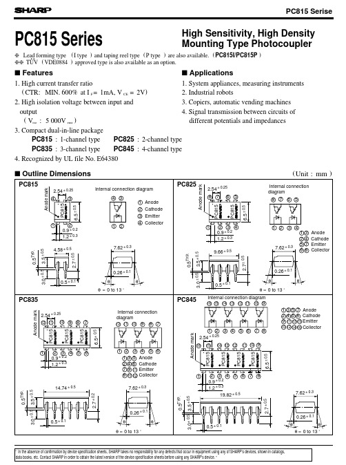
Fig. 9 Collector Dark Current vs.
Ambient Temperature
10 - 4
gg TUV ( VDE0884 ) approved type is also available as an option.
s Features
s Applications
1. High current transfer ratio
1. System appliances, measuring instruments
PC815 Series
s Absolute Maximum Ratings
Input Output
Parameter Forward current *1Peak forward current Reverse voltage Power dissipation Collector-emitter voltage Emitter-collector voltage Collector current Collector power dissipation Total power dissipation *2 Isolation voltage Operating temperature Storage temperature *3Soldering temperature
4. Recognized by UL file No. E64380
s Outline Dimensions
Anode mark PC815 6.5 ± 0.5
PC815
2.54 ± 0.25
4
3
1
2
0.9 ± 0.2
1.2 ± 0.3
Internal connection diagram
ads7951中文数据手册

ADS795112-Bit,1 MSPS8-Channel,单端,微功耗,串行接口的ADC特征:1: 1兆赫采样速率串行设备;2:12-Bit分辨率的产品系列;3:零延迟;4: 20 MHz的串行接口;5: 模拟电源电压范围:2.7至5.25V;6: 输入/输出范围:1.7到5.25v;7: 两个软件可选择单极性输入范围:0〜2.5V和0至5V;8: 自动和手动模式的信道选择;9: 8-channel设备可以共享16通道器件的足迹;10: 每个通道两个可编程的报警级别;11: 四个单独可配置的GPIO;12: 典型的功耗:14.5mW(Va=5V,+V BD=3V)1MSPS;13:断电电流:1 A;14:输入带宽(在3dB47);15:30引脚和38引脚TSSOP封装;描述:1:该元件包括基于电容与固有的采样SAR A / D转换和保持;2:该设备接受各种模拟供应范围从2.7V至5.25v。
非常低功耗使得这些设备适合电池供电的隔离电源应用;3:5.25VI/ O电源电压范围宽1.7V至促进与最常用的CMOS数码主机无胶接口;4:CS和SCLK串行接口控制,容易与微处理器和DSP连接;5:CS的下降沿采样输入信号。
它采用转换,串行数据输出SCLK 和阅读英寸串行数据设备允许自动测序预选频道或手动选择通道的下一个转换周期;6:有两种软件可选输入范围(0V - 2.5V和0V - 5V),4个可单独配置的GPIO,以及每个通道两个可编程告警阈值。
这些特点使设备适合大多数数据采集应用;7:该设备提供一个有吸引力的断电功能。
这是非常有用的节电设备运行时在较低的转换速度。
应用:1:可编程控制器/工控;2:电池供电系统;3:医疗器械;4:数字电源;5:触摸屏控制器;6:高速数据采集系统;7:高速闭环系统。
ADS系列框图:绝对最大额定值电气特性:+VA = 2.7 V to 5.25 V, +VBD = 1.7 V to 5.25 V, T A = -40°C to 125°C, f样本= 1 MHz(除非另有说明)系统性能:动态采样:设备信息引脚配置图(前视图):终端功能模拟输入多路复用器数字控制信号通用输入输出:这些引脚有可编程的双重功能.电源接地NC 引脚典型特征电源电流与电压静态电源电流与电源电压供应电流与空气温度静态电源电流与空气温度供应电流与采样率供应电流与采样率。
7951KWC中文资料

PRODUCT SPECIFICATION FMS7951FMS7951PRODUCT SPECIFICATIONTable 1. FunctionalityREF_SEL PLL_EN OE PLL All Outputs Input 001By Pass Hi-Z PECL_CLK000By Pass Running PECL_CLK010Enabled Running PECL_CLK101By Pass Hi-Z TCLK100By Pass Running TCLK110Enabled Running TCLKTable 2. Input Versus Output FrequencyDIV_SELA DIV_SELB DIV_SELC DIV_SELD QA QB QC QD 00002XREF REF REF REF00014XREF2XREF2XREF REF00102XREF REF1/2REF REF00114XREF2XREF REF REF01002XREF1/2REF REF REF01014XREF REF2XREF REF01102XREF1/2REF1/2REF REF01114XREF REF REF REF1000REF REF REF REF10012XREF2XREF2XREF REF1010REF REF1/2REF REF10112XREF2XREF REF REF1100REF1/2REF REF REF11012XREF REF2XREF REF1110REF1/2REF1/2REF REF11112XREF REF REF REFNote:1. Reference input could be either PECL_CLK or TCLK input.2. FBIN is tied to QD output for tableTable 3. Divide Select FunctionalityDIV_SEL A DIV_SEL B DIV_SEL D DIV_SEL D QA QB QC QD 0000÷2÷4÷4÷41111÷4÷8÷8÷8PRODUCT SPECIFICATIONFMS7951Absolute Maximum RatingsStresses greater than those listed in the table may cause permanent damage to the device. These represent a stress rating only. Operation of the device at these or any other conditions above those specified in the operating sections of this specification is not implied. Maximum conditions for extended periods may effect reliability.DC Electrical CharacteristicsT A = 0 to 70°C; Supply Voltage 3.3 V ±0.2V (unless otherwise stated) Note:1. Guaranteed by design, not subject to 100% production testing.AC Electrical CharacteristicsT A = 0 to 70°C; Supply Voltage V DD = 3.3V ±0.2V , CL = 10 pF (unless otherwise stated) Symbol ParameterRatings Units V DD , V IN Voltage on any pin with respect to ground -0.5 to 7.0V T STG Storage Temperature -65 to 150°C T B Ambient Temperature -55 to 125°C T AOperating Temperature0 to 70°CParameter Symbol Conditions Min.Typ.Max.Units Input Low Voltage V IL TCLK; control pins 0.8V Input High Voltage V IH TCLK; control pins 2.0 3.6V Input Low Current I IL V IN = 0-1010µA Input High Current I IH V IN = V DD-3030µA Peak to Peak Input VoltageV PP PECL_CLK/PCL_CLK0.3 1.0V Common Mode RangeV CMR V DD -2.0V DD -0.6mV Output Low Voltage V OL I OL = 40 mA 0.5V Output High Voltage V OH I OH = –40mA2.2V Input Capacitance (1) C IN 7.0pF Supply Current I DD Outputs loadedTBD150mA Clock Stabilization (1)T ST ABFrom VDD = 3.3V to 1% Target10mSParameter Symbol Conditions Min.Typ.Max.Units Input FrequencyF INFeedback Divide = 210175MHzFeedback Divide = 41085Feedback Divide = 81042TCLK Input Rise/Fall Time (1) T R_IN /T F_IN– 3.0ns TCLK Input Duty Cycle (1) D T_IN 2575%Output Frequency RangeF OUTQ A ; DIV_SEL A = 0V 175MHz Q B , Q C & Q D ;DIV_SEL B, C, D = 0V88MHz Output to Output Skew T SK1 V TH = V DD /2; DIV_SEL A = 0750pS V TH = V DD /2; DIV_SEL A = 1-300300Input to FBIN DelayTSK2TCLK 50400pS PECL_CLK-950-600FMS7951PRODUCT SPECIFICATION AC Electrical Characteristics (Cont.)T A = 0 to 70°C; Supply Voltage V DD = 3.3V ±0.2V, C L = 10 pF (unless otherwise stated)Parameter Symbol Conditions Min.Typ.Max.Units Rise Time(1)T R0.8 to 2.0V0.10 1.0nS Fall Time(1)T F 2.0 to 0.8V0.10 1.0nS Duty Cycle(1)D T V TH = V DD/24555% Jitter (Cycle-Cycle)T JIT QA: DIV_SEL A = 0450pSQA: DIV_SEL A = 1200QB Output200QC(0:1) Outputs300QD(0:4) Outputs375Note:1. Guaranteed by design, not subject to 100% production testing.PRODUCT SPECIFICATION FMS7951FMS7951PRODUCT SPECIFICATIONPRODUCT SPECIFICATION FMS7951DISCLAIMERFAIRCHILD SEMICONDUCTOR RESERVES THE RIGHT TO MAKE CHANGES WITHOUT FURTHER NOTICE TO ANY PRODUCTS HEREIN TO IMPROVE RELIABILITY, FUNCTION OR DESIGN. FAIRCHILD DOES NOT ASSUME ANYLIABILITY ARISING OUT OF THE APPLICATION OR USE OF ANY PRODUCT OR CIRCUIT DESCRIBED HEREIN; NEITHER DOES IT CONVEY ANY LICENSE UNDER ITS PATENT RIGHTS, NOR THE RIGHTS OF OTHERS.LIFE SUPPORT POLICYFAIRCHILD ’S PRODUCTS ARE NOT AUTHORIZED FOR USE AS CRITICAL COMPONENTS IN LIFE SUPPORT DEVICES OR SYSTEMS WITHOUT THE EXPRESS WRITTEN APPROVAL OF THE PRESIDENT OF FAIRCHILD SEMICONDUCTOR CORPORATION. As used herein:1.Life support devices or systems are devices or systemswhich, (a) are intended for surgical implant into the body, or (b) support or sustain life, or (c) whose failure to perform when properly used in accordance with instructions for use provided in the labeling, can be reasonably expected to result in significant injury to the user.2. A critical component is any component of a life supportdevice or system whose failure to perform can bereasonably expected to cause the failure of the life support device or system, or to affect its safety or effectiveness.。
PC929中文资料

g TÜV ( VDE 0884 ) approved type is also available as an option.
s Features 1. Built-in IGBT shortcircuit protector circuit 2. Built-in direct drive circuit for IGBT drive
V
VCC = V01 = 24V, RG = 47Ω
6.5 6.0 5.5
CG = 3 000pF, FS = OPEN
1
2
3
V
(9)
*9
O2 "High→Low" delay time at protection from overcurrent
tPCOHL
Ta = 25˚C
-
4
10
µs
O2 fall time at protection from overcurrent
Amp.
1 2 3 4 5 67
1 Cathode 2 Cathode 3 Anode 4 NC 5 NC 6 NC 7 NC
8 FS
9C
10 GND
11 O2 12 O1 13 VCC 14 GND
Terminals 4 to 7 : Shortcircuit in element
* "OPIC" (Optical IC) is a trademark of the SHARP Corporation. An OPIC consists of a light-detecting element and signal processing circuit integrated onto a single chip.
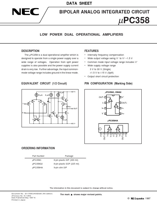
C358C的应用
RL = 2 kΩ 80
40
0
10
20
30
40
V+ - Supply Voltage - V (V– = GND)
COMMON MODE REJECTION RATIO 120
100
80
60
40
f - Frequency - Hz
PT - Total Power Dissipation - mW
POWER DISSIPATION 600
500 µPC358G2 400 300 µPC358C, 358HA
200
100
0
20 40 60 80 100
TA - Operating Ambient Temperature - °C
120
dB
Note 7. Input bias currents flow out from IC. Because each currents are base current of PNP-transistor on input stage.
2
µPC358
TYPICAL PERFORMANCE CHARACTERISTICS (TA = 25 °C, TYP.)
–4–50
0
50
100
TA - Operating Ambient Temperature - ˚C
IB - Input Bias Current - nA
INPUT BIAS CURRENT 100
75
50
TA = 25 °C
25
0
10
20
30
40
V+ - Supply Voltage - V (V– = GND)
C8991资料

GENERALFEATURESSPECIFICATIONS ParameterDescription/ValueUnit Output High Voltage Range Input Voltage RangeControl Voltage / Output Voltage Ratio Control Voltage Range Settling Time AOutput Signal ModeOperating Ambient Temperature B Storage Temperature B WeightI Compact and LightweightI Low Power Consumption (8 mA Max., without signal output)I Wide Output LinearityI No Handling of High Voltage I Easy Handling-200 to -1200+11.5 to +15.51 : 103+0.2 to +1.210Current output 0 to +50-15 to +60Approx. 71V V —V s —°C °C gCHARACTERISTlCS (at +25 °C, -1000 V)DP TYPE SOCKET ASSEMBLYFOR 28 mm(1-1/8 INCH) SIDE-ON PHOTOMULTIPLIER TUBEC8991MAXIMUM RATINGS (Absolute Maximum Values)ParameterValue Output High Voltage Supply Voltage Control Voltage-1200+18+1.2V V VUnit ParameterValue Input Current (Without signal input)Temperature Coefficient (+20 °C to +40 °C)Anode Ripple Interference CLinear DC Output Current of PMT DTyp.Max.Max.Typ.80.0050.011100mA %/°C %/°C mV µAUnit C R L = 1 M Ω, C L = 25 pFD Within ±0.5 % linearityNOTE:A The time required for the output to reach a stable level following a change in the control voltage from +1.0 V to +0.5 V.B No condensation.NOTE:High Voltage Power Supply and Divider Assemblyfor Standard 28 mm (1-1/8 inch) Side-on Photomultiplier TubeThe C8991 is a compact and lightweight socket assembly incorpor-ating a socket, voltage divider circuit and high voltage power supply designed for use with 28 mm(1-1/8") side-on type photomultiplier tube. It features low power consumption and superior output linearity comparing with conventional socket assemblies. In addition, it allows easy handling to operate with +15 V input voltage and connecting to a potentiometer or a +0.2 V to +1.2 V for output voltage adjustments.FEB. 2004Information furnished by HAMAMATSU is believed to be reliable. However, no responsibility is assumed for possible inaccuracies or omissions. Specifications are subject to change without notice. No patent rights are granted to any of the circuits described herein. ©2004 Hamamatsu Photonics K.K.Subject to local technical requirements and regulations, availability of products included in this promotional material may vary. Please consult with our sales office.* HV cont. Input: Impedance of 1 M ΩDP TYPE SOCKET ASSEMBLY C8991TACC1027E02FEB. 2004 IPTACCB0008EATACCC0117EATACCA0053EDFigure 1: Control Voltage/Output Voltage CharacteristicsFigure 2: Sensitivity Adjustment MethodeFigure 3: Dimensional Outline (Unit: mm)CONTROL VOLTAGE (V)+0.2+0.6+1.2O U T P U T V O L T A G E (V )-200-400+0.4+0.8+1.0-600-800-1000-12001)1)VOLTAGE PROGRAMMINGRESISTANCE PROGRAMMINGhigh voltage output.*The case is internally connected to black (GND) wire.Top ViewSide ViewHOUSING DIRECTION OF LIGHTSIGNAL OUTPUT +15 V INPUTHV CONTROL INPUT Vref OUTPUT GROUNDCOAX RG-174/U AWG 22, RED AWG 22, WHITE AWG 22, BLUE AWG 22, BLACKHAMAMATSU PHOTONICS K.K., Electron Tube Division314-5, Shimokanzo, Toyooka-village, Iwata-gun, Shizuoka-ken, 438-0193, Japan, Telephone: (81)539/62-5248, Fax: (81)539/62-2205U.S.A.: Hamamatsu Corporation: 360 Foothill Road, P. O. Box 6910, Bridgewater. N.J. 08807-0910, U.S.A., Telephone: (1)908-231-0960, Fax: (1)908-231-1218 E-mail: usa@Germany: Hamamatsu Photonics Deutschland GmbH: Arzbergerstr. 10, D-82211 Herrsching am Ammersee, Germany, Telephone: (49)8152-375-0, Fax: (49)8152-2658 E-mail: info@hamamatsu.deFrance: Hamamatsu Photonics France S.A.R.L.: 8, Rue du Saule Trapu, Parc du Moulin de Massy, 91882 Massy Cedex, France, Telephone: (33)1 69 53 71 00, Fax: (33)1 69 53 71 10 E-mail: infos@hamamatsu.frUnited Kingdom: Hamamatsu Photonics UK Limited: 2 Howard Court, 10 Tewin Road Welwyn Garden City Hertfordshire AL7 1BW, United Kingdom, Telephone: 44-(0)1707-294888, Fax: 44(0)1707-325777 E-mail: info@ North Europe: Hamamatsu Photonics Norden AB: Smidesv ägen 12, SE-171-41 SOLNA, Sweden, Telephone: (46)8-509-031-00, Fax: (46)8-509-031-01 E-mail: info@hamamatsu.se Italy: Hamamatsu Photonics Italia: S.R.L.: Strada della Moia, 1/E, 20020 Arese, (Milano), Italy, Telephone: (39)02-935 81 733, Fax: (39)02-935 81 741 E-mail: info@hamamatsu.itWEB SITE 。
- 1、下载文档前请自行甄别文档内容的完整性,平台不提供额外的编辑、内容补充、找答案等附加服务。
- 2、"仅部分预览"的文档,不可在线预览部分如存在完整性等问题,可反馈申请退款(可完整预览的文档不适用该条件!)。
- 3、如文档侵犯您的权益,请联系客服反馈,我们会尽快为您处理(人工客服工作时间:9:00-18:30)。
.300 (7.6)
30
.150 (3.8)
Holes for Pins 30, 87 & 87a are 3 X .087 (2.2) by .063 (1.6) Pins 85 & 86 are .079 (2.0) by .047 (1.2)
Notes:
Tolerances + .010 unless otherwise noted Maximum make current refers to inrush of a lamp load In 85 degree C ambient reduce maximum coil voltage to 72%
ORDERING INFORMATION
Example: PC795 -1C -C1 -12 S -RN Model
Contact Form 1A, 1C or 1U (1 form A with 2 #87 Terminals)
Case Style C: Plug-In; P: PCB; C1: Plastic Bracket; C3: Shrouded W/Metal Bkt Coil Voltage
.709
(18.0)
.275
(7.0)
.181 (4.6)
.591 (15.0)
.236 (6.0)
.252 Dia. (6.4)
.811 (20.6)
.630 (16.0)
.210 Dia. (5.3)
1.78 (45.3)
.984 (25.0)
1.10 (28.0)
1.10 (28.0)
Metal Bracket (C2)
3220 Commander Drive, Suite 102, Carrollton, Texas 75006 Sales: Call Toll Free (888) 997-3933 Fax (818) 342-5296 email: pickerwest@ URL:
PAGE 2
元器件交易网
PC795
PC795
.165 (4.2)
.630 (16.0)
.866 (22.0)
.236 (6.0)
.252 Dia. (6.4)
.984 (25.0)
1.10 (28.0)
1.10 (28.0)
Molded Plastic Bracket (C1)
PAGE 1
元器件交易网
PC795
REFERENCE CURVE
Contact Derating 80
Current in Amps
60
40
20
0 10 20 30 40 50 100 DC Contact Voltage.
COIL DATA
Coil Voltage
6 12 24
Make 240 Amps
Make 180 Amps
Break 80 Amps
Break 60 Amps
Current Dependent; see curve page 2
80 Amps
60 Amps
0.5 A @ 12 VDC
CONTACT DATA
Material
AgSnOInO (Silver Tin Oxide Indium Oxide)
Initial Contact Resistance Mechanical
Service Life Electrical
100 milliohms max @ 0.1A, 6VDC 1 X 10⁷ Operations 2 X 10 5 Operations
CHARACTERISTICS
Operate Time Release Time Insulation Resistance Dielectric Strength Shock Resistance Vibration Resistance Drop Resistance Power Consumption Ambient Temperature Range Weight
.524 (13.3)
1.42 (36.0)
1.42 (36.0)
Skirted Case with Metal Bracket (C4)
.409 (10.4)
Bent Metal Bracket (C3)
Skirted Case with Bent Metal Bracket (C5)
3220 Commander Drive, Suite 102, Carrollton, Texas 75006 Sales: Call Toll Free (888) 997-3933 Fax (818) 342-5296 email: pickerwest@ URL:
.984 (25.0)
1.10 (28.0)
.331 (8.4)
87
87A
86
85
30
.315 (8.0)
.705 (17.9)
Form 1A
30 87
Form 1C
87a 30
87
85
86
85
86
(+)
(-)
(+)
(-)
Wiring Diagrams
.331 (8.4)
87
87ALeabharlann 8685.315 (8.0)
Resistance ohms +_ 10%
22 90 330
Must Operate Voltage Max.
(VDC)
3.6 7.2 14.3
Must Release Voltage Min.
(VDC)
0.6 1.2 2.4
Plug-In Type
Dimensions in Inches (millimeters)
PAGE 3
Plug-In Case (C) and PCB Case (P)
.453 (11.5)
.665 (16.9)
PC795
Continuous Voltage Max.
(VDC) 10.1 20.5 39.1
Bottom View
.665 (16.9)
.250 (6.3)
.374 (9.5)
.709 (18.0)
Enclosure C: Dust Cover, S: Sealed Case Parallel Component Nil: None; D: Diode; R: Resistor; N: Nickel Plated Terminals
PC795 Rev C 4-13-04
3220 Commander Drive, Suite 102, Carrollton, Texas 75006 Sales: Call Toll Free (888)997-3933 Fax (818) 342-5296 email: pickerwest@ URL:
7 ms. typical 2 ms. typical 100 megohms min, at 500VDC, 50%RH 500 Vrms, 1 min. between coil and contacts 20 g, 11ms, functional; 200 g, destructive DA 1.27 mm, 10 - 40 Hz; 40-70 Hz: 5 g; DA 0.5mm, 70-100 Hz; 100-500 Hz: 10 g. 1 Meter height drop on concrete in final enclosure 1.6 W approx. -40 to 125 degrees C operating, -40 to 155 storage 35 grams approx.
CONTACT RATINGS
Contact Form
Max Switching Current
Max. Switching Voltage Max. Continuous Current Minimum Load
1 Form A or 1 Form C
Normally Open
Normally Closed
元器件交易网
80/60 Amp Automotive Plug-In / PCB Power Relay
PC795
FEATURES Most popular automotive relay 1 A and 1 C contact forms available Contact switching capacity up to 240 Amps 80 Amps continuous carrying capacity Up to 125 degrees C operating temperature Five different case styles available Sockets available from Picker Components
