BHX1-LR44-SM, 规格书,Datasheet 资料
XNX系列氢氧化物传感器的产品介绍说明书
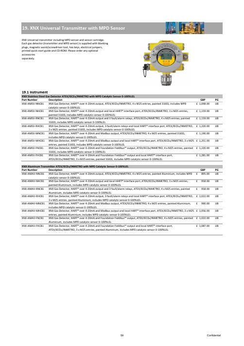
XNX Gas Detector, HART® over 4-20mA output, ATEX/IECEx/INMETRO, 4 x M25 entries, painted 316SS, includes MPD XNX Gas Detector, HART® over 4-20mA output and local HART® interface port, ATEX/IECEx/INMETRO, 3 x M25 entries, XNX Gas Detector, HART® over 4-20mA output and 3 fault/alarm relays, ATEX/IECEx/INMETRO, 4 x M25 entries, painted6970Confidential71Confidential72Confidential73ConfidentialPart NumberDescriptionPGXNX-AMAE-FNNNN XNX Transmitter, HART® over 4-20mA and Foundation Fieldbus™ output, ATEX/IECEx/INMETRO, 4 x M25 entries, painted Aluminium, configured for XNX toxic and oxygen sensors895.00£ UB XNX-AMAE-FHNNNXNX Transmitter, HART® over 4-20mA and Foundation Fieldbus™ output and local HART® interface port, ATEX/IECEx/INMETRO, 3 x M25 entries, painted Aluminium, configured for XNX toxic and oxygen sensors958.00£ UBXNX Stainless Steel Transmitter UL/CSA for use with XNX Toxic and Oxygen Sensors Part Number Description GBP PGXNX-UTSE-NNNNN XNX Transmitter, HART® over 4-20mA output, UL/CSA, 4 x 3/4"NPT entries, painted 316SS, configured forXNX toxic and oxygen sensors975.00£ UB XNX-UTSE-NHNNN XNX Transmitter, HART® over 4-20mA output and local HART® interface port, UL/CSA, 3 x 3/4"NPTentries, painted 316SS, configured for XNX toxic and oxygen sensors1,037.00£ UB XNX-UTSE-RNNNN XNX Transmitter, HART® over 4-20mA output and 3 fault/alarm relays, UL/CSA, 4 x 3/4"NPT entries,painted 316SS, configured for XNX toxic and oxygen sensors1,037.00£ UB XNX-UTSE-RHNNN XNX Transmitter, HART® over 4-20mA output and 3 fault/alarm relays and local HART® interface port,UL/CSA, 3 x 3/4"NPT entries, painted 316SS, configured for XNX toxic and oxygen sensors 1,098.00£ UB XNX-UTSE-MNNNN XNX Transmitter, HART® over 4-20mA and Modbus output, UL/CSA, 4 x 3/4"NPT entries, painted 316SS, configured for XNX toxic and oxygen sensors1,068.00£ UB XNX-UTSE-MHNNN XNX Transmitter, HART® over 4-20mA and Modbus output and local HART® interface port, UL/CSA, 3 x 3/4"NPT entries, painted 316SS, configured for XNX toxic and oxygen sensors1,128.00£ UB XNX-UTSE-FNNNN XNX Transmitter, HART® over 4-20mA and Foundation Fieldbus™ output, UL/CSA, 4 x 3/4"NPT entries, painted 316SS, configured for XNX toxic and oxygen sensors1,098.00£ UB XNX-UTSE-FHNNNXNX Transmitter, HART® over 4-20mA and Foundation Fieldbus™ output and local HART® interface port, UL/CSA, 3 x 3/4"NPT entries, painted 316SS, configured for XNX toxic and oxygen sensors1,159.00£ UBXNX Aluminium Transmitter UL/CSA for use with XNX Toxic and Oxygen Sensors Part Number Description GBP PGXNX-UTAE-NNNNN XNX Transmitter, HART® over 4-20mA output, UL/CSA, 4 x 3/4"NPT entries, painted Aluminium,configured for XNX toxic and oxygen sensors767.00£ UB XNX-UTAE-NHNNN XNX Transmitter, HART® over 4-20mA output and local HART® interface port, UL/CSA, 3 x 3/4"NPTentries, painted Aluminium, configured for XNX toxic and oxygen sensors831.00£ UB XNX-UTAE-RNNNN XNX Transmitter, HART® over 4-20mA output and 3 fault/alarm relays, UL/CSA, 4 x 3/4"NPT entries,painted Aluminium, configured for XNX toxic and oxygen sensors831.00£ UB XNX-UTAE-RHNNN XNX Transmitter, HART® over 4-20mA output and 3 fault/alarm relays and local HART® interface port,UL/CSA, 3 x 3/4"NPT entries, painted Aluminium, configured for XNX toxic and oxygen sensors 895.00£ UB XNX-UTAE-MNNNN XNX Transmitter, HART® over 4-20mA and Modbus output, UL/CSA, 4 x 3/4"NPT entries, painted Aluminium, configured for XNX toxic and oxygen sensors863.00£ UB XNX-UTAE-MHNNN XNX Transmitter, HART® over 4-20mA and Modbus output and local HART® interface port, UL/CSA, 3 x 3/4"NPT entries, painted Aluminium, configured for XNX toxic and oxygen sensors927.00£ UB XNX-UTAE-FNNNN XNX Transmitter, HART® over 4-20mA and Foundation Fieldbus™ output, UL/CSA, 4 x 3/4"NPT entries, painted Aluminium, configured for XNX toxic and oxygen sensors895.00£ UB XNX-UTAE-FHNNNXNX Transmitter, HART® over 4-20mA and Foundation Fieldbus™ output and local HART® interface port, UL/CSA, 3 x 3/4"NPT entries, painted Aluminium, configured for XNX toxic and oxygen sensors958.00£ UB74Confidential75Confidential76Confidential77ConfidentialXNX Aluminuim Transmitter ATEX/IEC for use with Optima Plus and Searchline Excel Detectors78ConfidentialXNX Aluminuim Transmitter UL/CSA for use with Optima Plus and Searchline Excel DetectorsExcel kits including standard XNX transmitter configured with HART® over 4-20mA output and local IS HART® port. For Excel kits includingother XNX transmitter configurations contact Honeywell Analytics. A calibration has to be ordered with every XNX Excel kit.Excel gas calibration curve to be selected from section 29.2 and to be ordered additionally.23.1 InstrumentExcel kits including standard XNX transmitter with HART® over 4-20mA outputs and local IS HART® port.Excel Short Range 5m – 40m (15ft - 130ft)Part Number Description GBP PG 02104-N-XSAA XNX Excel line-of-sight gas detection system, short range (5 to 40m), 4 to 20mA and HART® outputs, ATEX/IECEx, fully wired with flexible conduit, electro polished 316SS. Includes Tx, Rx, aluminimum XNX, Ex e junction box with M20/M25 cable entries, 316SS mounting plates, brackets and hardware 6,518.00£ UA02104-N-XSSAXNX Excel line-of-sight gas detection system, short range (5 to 40m), 4 to 20mA and HART® outputs, ATEX/IECEx, fully wired with flexible conduit, electro polished 316SS. Includes Tx, Rx, stainless steel XNX, Ex e junction box with M20/M25 cable entries, 316SS mounting plates, brackets and hardware6,649.00£ UA 02104-N-XSAUXNX Excel line-of-sight gas detection system, short range (5 to 40m), 4 to 20mA and HART® outputs, UL, fully wired with flexible conduit, electro polished 316SS. Includes Tx, Rx, aluminimum XNX, junction box with 3/4"NPT cable entries, 316SS mounting plates, brackets and hardware6,827.00£ UA 02104-N-XSSUXNX Excel line-of-sight gas detection system, short range (5 to 40m), 4 to 20mA and HART® outputs, UL, fully wired with flexible conduit, electro polished 316SS. Includes Tx, Rx, stainless steel XNX, junction box with 3/4"NPT cable entries, 316SS mounting plates, brackets and hardware6,960.00£ UA 02104-N-XSACXNX Excel line-of-sight gas detection system, short range (5 to 40m), 4 to 20mA and HART® outputs, FM/CSA, fully wired with flexible conduit, electro polished 316SS. Includes Tx, Rx, aluminimum XNX, junction box with 3/4"NPT cable entries, 316SS mounting plates, brackets and hardware6,539.00£ UA 02104-N-XSSCXNX Excel line-of-sight gas detection system, short range (5 to 40m), 4 to 20mA and HART® outputs, FM/CSA, fully wired with flexible conduit, electro polished 316SS. Includes Tx, Rx, stainless steel XNX, junction box with 3/4"NPT cable entries, 316SS mounting plates, brackets and hardware6,671.00£ UA 02104-N-NSNAExcel line-of-sight gas detection system (without XNX, please order required XNX separately), short range (5 to 40m), 4 to 20mA output, ATEX/IECEx, fully wired with flexible conduit, electro polished 316SS. Includes Tx, Rx, 316SS mounting plates, brackets and hardware. XNX and junciton boxes to be ordered seperately.5,591.00£ UA83Confidential。
LR1154(LR44)新规格书

丰力电池有限公司ALKALINE ZINC-MANGANESE DIOXIDE MERCURY-FREE BUTTON CELL型号(MODEL):LR44 0.0Hg碱性锌锰扣式电池TECHNICAL SPECIFICATION技术规格书制定:Huang Ting Piao申批:Hong ze hong规格编号:CKJ.FL-LR44版本号:2015-A44-1日期:2015-03(本公司有更改产品规格书及任何资料的权力,且无须预先通知。
)第1页,共6页负载电阻:7.5k扣式碱性电池LR441、Scope 适用范围This specification is applicable to our Accell alkaline zinc –manganese dioxide mercury-free button cell :LR44该规格书适用于由丰力电池有限公司碱性锌-二氧化锰无汞扣式电池:LR44。
2、产品类型TYPE名称Model:LR44(LR1154)IEC命名:LR443、化学构成分子式CHEMICAL STRUCTURE(+)锌--二氧化锰(碱性电解液) (-) Zn|KOH|MnO2汞含量测试结果(TESTING RESULT OF MERCURY) :Hg<5ppm(0.0005%)镉含量测试结果(TESTING RESULT OF NICKLE) :Cd<5ppm(0.0005%)铝含量测试结果(TESTING RESULT OF ALUMINIUM) :Pb<5ppm(0.0005%)4、技术规格PRODUCT SPECIFICATION4.1规格尺寸高度(H)5.40mm直径(Φ)11.60mm4.2平均重量 Average weight: 1.86g4.3额定电压 Nommal voltage 1.50V4.4典型容量Typical capacity: 120mAh(在20±2℃条件下,用1KΩ负载电阻连续放电,终止电压0.90V)。
海斯特产品目录(彩色)

佛山市海斯特密封技术有限公司佛山市海斯特密封技术有限公司地址:广东省佛山市禅城区平远北街平西新村15号3楼东邮编:528041电话:+86-0757-******** / 83134290 / 83819359 / 83875181 / 83875182传真:+86-0757-******** / 83819359网址: 邮箱:sales@Add:15Pingxi Xincun ,Pingyuan Street North,Suite3A, Foshan,Guangdong PC.:528041T e l :+86-0757-******** / 83134290 / 83819359 / 83875181 / 83875182Fax:+86-0757-******** / 83819359Web: E-mail:sales@Foshan Hiseal Industry and Trade Co.,Ltd密封设计选型指南密封设计选型指南佛山市海斯特密封技术有限公司目 录目 录密封件一览表活塞密封活塞杆密封防尘圈耐磨环旋转密封弹簧施力密封O形圈其它密封安装指南质量及贮存准则27 51 75 119 133 139 151 157 161163活塞密封:活塞杆密封:防尘圈:耐磨环:旋转密封:弹簧施力密封:O 形圈:H30活塞密封H30活塞密封双向活塞密封密封件一览表注:以上表中以及本书中所列工作参数数据是最大值,各参数之间相互制约,相互关联,因度范围也与具体工作介质密切相关。
此不能同时使用。
比如最高压力取决于具体材料类型、工作温度、速度和间隙尺寸等,而温表面粗糙度 Ra 0.05-0.3<1.6Rz <1.6<10.0Rmax.<2.5<16.0配合表面µm 沟槽表面µm 1.说明H30活塞密封是双向作用的活塞密封,由一个填充聚四氟乙烯密封环和一个O形圈组成。
Schneider Electric XUSL4E14F031N 产品数据手册说明书

T h e i n f o r m a t i o n p r o v i d e d i n t h i s d o c u m e n t a t i o n c o n t a i n s g e n e r a l d e s c r i p t i o n s a n d /o r t e c h n i c a l c h a r a c t e r i s t i c s o f t h e p e r f o r m a n c e o f t h e p r o d u c t s c o n t a i n e d h e r e i n .T h i s d o c u m e n t a t i o n i s n o t i n t e n d e d a s a s u b s t i t u t e f o r a n d i s n o t t o b e u s e d f o r d e t e r m i n i n g s u i t a b i l i t y o r r e l i a b i l i t y o f t h e s e p r o d u c t s f o r s p e c i f i c u s e r a p p l i c a t i o n s .I t i s t h e d u t y o f a n y s u c h u s e r o r i n t e g r a t o r t o p e r f o r m t h e a p p r o p r i a t e a n d c o m p l e t e r i s k a n a l y s i s , e v a l u a t i o n a n d t e s t i n g o f t h e p r o d u c t s w i t h r e s p e c t t o t h e r e l e v a n t s p e c i f i c a p p l i c a t i o n o r u s e t h e r e o f .N e i t h e r S c h n e i d e r E l e c t r i c I n d u s t r i e s S A S n o r a n y o f i t s a f f i l i a t e s o r s u b s i d i a r i e s s h a l l b e r e s p o n s i b l e o r l i a b l e f o r m i s u s e o f t h e i n f o r m a t i o n c o n t a i n e d h e r e i n .Product data sheetCharacteristicsXUSL4E14F031NXUSL type 4 - Finger protection - Std sensingrange - Hp = 310 mm, R=14mmProduct availability: Non-Stock - Not normally stocked in distribution facilityMainRange of product Preventa Safety detection Product or component typeSafety light curtain type 4Device short name XUSL4EOutput type2 safety outputs OSSD solid-state PNP arc suppres-sion)Product specific applica-tionFor finger protection [R] Resolution 0.55 in (14 mm)[Sn] nominal sensing distance3.28…19.69 Ft (1…6 m) by cabling 0.00…9.84 ft (0…3 m) by cabling [Hp] Height protected 12.20 in (310 mm)Number of beams 30Type of start / restart Manual Automatic External Device Moni-toring (EDM)Selected by wiringComplementaryDetection system Transmitter-receiver system Response time 5.5 msKit compositionAdjustable mounting bracket(s)1 receiver(s)1 transmitter(s)1 user guide with certificate of conformity on CD-ROM [EAA] effective aperture angle 2.5 ° at 3 mEmissionIR LED 0.000037402 in (950 nm)[Us] rated supply voltage 24 V DC +/- 20 %SupplyPower supply IEC 61496-1Power supply IEC 60204-1[Ie] rated operational current 2 ACurrent consumption42 mA no-load transmitter 83 mA no-load receiver 42 mA transmitter900 mA with maximum load receiver Output current limits 0.4 A safety outputs OSSD Output voltage 24 V Output circuit type DC Maximum voltage drop <0.5 VLocal signalling 1 multi-colour LED transmitter 2 dual colour LEDs receiverElectrical connection 1 male connector M12 5 pins transmitter 1 male connector M12 8 pins receiverFunction availableTestMuting through external safety module XPSLCMUT1160LED display of operating modes and faults Marking CEMaterialAluminium casingPolycarbonate front panel Polypropylene end caps Housing colourRed RAL 3000Fixing mode By fixing bracketsNet weight 1.54 lb(US) (0.7 kg)Offer type Standard distanceEnvironmentDirectives89/336/EEC - electromagnetic compatibility2002/95/EC - RoHS directive98/37/EEC - machinery89/655/EEC - work equipment2002/96/EC - WEEE directiveProduct certifications CULusCETÜVSafety level (correctly wired)Type 4 IEC 61496-1SIL 3 IEC 61508SILCL 3 IEC 62061Category 4 EN/ISO 13849-1PL = e EN/ISO 13849-1Optical characteristic Resistance to light disturbance EN/IEC 61496-2Mission time20 year(s)Safety reliability data PFHd = 1.27E-8 1/h IEC 61508Ambient air temperature for operation-10…55 °C (14…131 °F)-4…131 °F (-20…55 °C)Ambient air temperature for storage-31…158 °F (-35…70 °C)-25…70 °C (-13…158 °F)Relative humidity0…95 % without condensationIP degree of protection IP65IP67Shock resistance10 gn 16 ms IEC 61496-1Vibration resistance0.35 +/- 0.05 mm 10…55 Hz)IEC 61496-1Ordering and shipping detailsCategory22455 - LIGHT CURTAINS - XUSLDiscount Schedule DS2GTIN00785901735632Package weight(Lbs) 1.58 kg (3.49 lb(US))Returnability YesCountry of origin ITOffer SustainabilitySustainable offer status Green Premium productREACh Regulation REACh DeclarationEU RoHS Directive Pro-active compliance (Product out of EU RoHS legal scope)EU RoHS Decla-rationToxic heavy metal free YesMercury free YesRoHS exemption information YesEnvironmental Disclosure Product Environmental ProfileCircularity Profile End Of Life InformationContractual warrantyWarranty18 monthsDimensions Drawings DimensionsBrackets DimensionsMounting and Clearance Mounting and Clearance(1)Insert(2)Bracket(3)Washer(4)Spring washer(5)NutConnections and SchemaWiring DiagramsTransmitter Connections(1)+24 Vdc(2)Configuration_0(3)0 Vdc(4)Configuration_1(5)FEReceiver Connections(1)OSSD1(2)+ 24 V(3)OSSD2(4)Configuration_A(5)K1_K2 Feeback/Restart(6)Configuration_B(7)0 Vdc(8)FEReceiver Configurations and Operating ModesAutomatic Start/RestartWithout External Device Monitoring (EDM) feedback loopWith External Device Monitoring (EDM) feedback loopManual Start/RestartWithout External Device Monitoring (EDM) feedback loop(1)RestartWith External Device Monitoring (EDM) feedback loop(1)RestartConnecting to a Safety Interface1 :Click on Download & Documents2 :Click on Application solutionsTo have all connection schematics concerning our safety module, select "download and document" and download the file "Safety lightcurtains association with safety interfaces"。
伊玛产品类别

18~36 VDC
PNP NO/NC,NPN NO/NC
4~20 mA,0~10 V
可
PA1108
智慧型
7 LED
内螺纹
G 1/4
400 bar
四线
18~36 VDC
PNP NO/NC,NPN NO/NC
4~20 mA,0~10 V
可
PA1109
智慧型
7 LED
内螺纹
G 1/4
2 bar
四线
18~36 VDC
200
60
M12
接插件
N
Y
N
IP67
否
IA0031
齐平
brass
10~36VDC
1
两线
NO
DC PNP/NPN
200
60
M12
接插件
N
Y
N
IP67
否
IA0032
齐平
brass
10~36VDC
1
两线
NC
DC PNP/NPN
200
60
M12
接插件
N
Y
N
IP67
否
IA0033
非齐平
brass
10~36VDC
可
TA1099
智慧型
7 LED
内螺纹
M18 X 1.5
-40~150°C
四线
20~30 VDC
PNP NO/NC,NPN NO/NC
4~20 mA,0~10 V
可
产品类别
压力变送器(模拟量输出)
压力变送器(开关量输出)
订货号
功能
显示
牙口形式
Schmersal PROTECT系列产品说明书
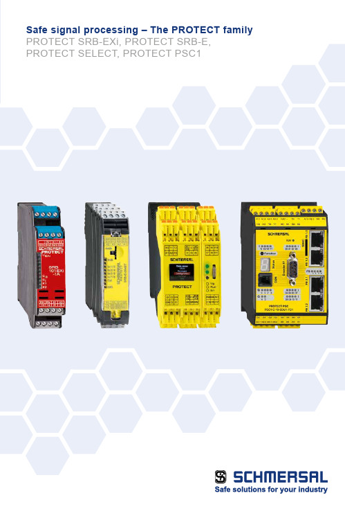
Depending on the complexity and number of safety circuits, the Schmersal Group provides solutions for reliable signal analysis based on safety control modules and safety controllers with an array of visualisation and diagnostic possibilities.PROTECT SRB modules ■ M ulti-purpose use, easy installation, low cost solution ■ S RB-E-series covers a broad range of applications with eight versions ■ S RB EXi modules with ATEX, IECEx and INMETRO approvals ■ S RB301ST for lift applications,certified in accordance with EN 81-20/50Safe signal processingThe complete Schmersal portfolioPROTECT- SELECT ■ U p to 6 safety functions can be realised ■ A daptation to individual requirements thanks to simple parameterisation ■ V arious parameters such as short circuit monitoring can be configured ■ S ave space in the control cabinet ■ D isplay of clear text messages duringtroubleshootingComplexSafety relay module PROTECT SRB-ESafety controller PROTECT PSCPROTECT SELECT safety moduleHigh costLow costSimpleNumber of safety functions1 - 34 - 9> 10Modular safety compact controller PROTECT PSC1■Freely programmable compact controller PSC1-C-10 and PSC1-C-100■ P rogramming software SafePLC2: Modern, object oriented application development environment ■ »Save Drive Monitoring« module (SDM) monitors up to 12 axes ■ U niversal communication interface for all common field-bus systems ■ M odular expansion with up to 272 inputs/ outputsCentral structure:I/O expansion modulesModular compact controller PROTECT PSC1PROTECT PSC1-C-10: up to 2 expansion modules / 64 I/OsPROTECT PSC1-C-100: up to 8 expansion modules / 272 I/OsThe compact controller PROTECT PSC1-C-10 can be expanded with up to 2 I/O expansion modules.A mixture of centralised and decentralised structures can be used.The compact controller PROTECT PSC1-C-100 can be expanded with up to 8 I/O expansion modules.A mixture of centralised and decentralised structures can be used.Central structure:I/O expansion modulesDecentral structure:Expandable with the remote I/O moduleDecentral structure:Expandable with theremote I/O module• • •Safe Drive Monitoring (SDM) for PROTECT PSC 1Safe drive monitoring for up to 12 axesFor safe drive monitoring many safety features are supported:■ S afe shut-down: Safe Torque OFF (STO), Safe Brake Control (SBC)■ S afe stopping: Safe Stop 1 (SS1), Safe Stop 2 (SS2), Safe Operating Stop (SOS)■ S afe movement: Safely-Limited Speed (SLS), Safe Speed Range (SSR), Safe Direction (SDI),Safely-Limited Acceleration (SLA), Safe Acceleration Range (SAR)■ S afe monitoring: Safe Speed Monitor (SSM), Safe Cam (SCA)■ S afe Positioning: Safely-Limited Position (SLP), Safely-Limited Increment (SLI),Safely Emergency Limit (SEL)The drive monitoring is carried out depending on the application requirements, with one or two encoder systems.The following encoder signals are supported:■ 1 encoder system: TTL, SIN/COS, SSI (Gray code / binary code)■ 2 Encoder systems: TTL, SIN/COS, SSI (Gray code / binary code), Resolver, HTLPROTECT - SELECTMulti-functional Safety Module with Program Selection Function With the multi-functional PROTECT SELECT compact safety module, the engineer has greater flexibilityduring configuration of the safety device and its subsequent integration into the machine functions.Four different programs are available. Each program can beprecisely adapted – without any programming knowledge,simply with the menu and clear text messages – to the specificapplication case. This allows for example the release delayand the de-bounce time to be set individually, and numerousparameters such as the cross-wire monitoring to be set asrequired – a definite advantage in comparison to safety relaymodules.With every application program the user profits from numerousfunctions – such as:■C onnection of up to six dual-channel safety switching devices(with or without potential) up to PL e / SIL 3■S afety semi-conductor and relay outputs with STOP 0 orSTOP 1 function■S afe analogue monitoring of temperature and other processvariables■F ree assignment of start-up tests, periodic tests, auto-start,manual start■C ross-wire detection■ Display of clear text messages during troubleshooting■ Input filter for safety devices with contact bouncePROTECT SRB-E modulesSafe signal processing for a range of applicationsAll eight versions of the new family of safety relay modules PROTECT SRB-E can be used in applications up toCat. 4 / PL e in accordance with EN ISO 13849-1 and up to SIL 3 in accordance with EN 62061 / IEC 61508.A major advantage of the new PROTECT SRB-E series is its multi-functionality which allows all the variants to be usedwith several dozen existing SRB modules. Each module can be configured for up to eleven different applications via asimple control element. All conventional safety sensors and electromechanical safety equipment can be monitored.The drastic reduction in the number of variants and the clear display of the relevant functions makes it considerablyeasier for the machine manufacturer to select the right module for their particular application. Adjustable configuration and applicationsFlexible■1 or 2 channel signal evaluation■C ontact configuration can be selected for the sensors■S tart / Reset functionswith monitoring■I nput expanders for4 sensors up to PL e■C ascading via safe inputs■C ombined evaluationfor 2 safety guards■T wo-hand control monitoring ■S TOP Category 0 and 1■U p to 5 safety outputs■S afety category 4, PL e semi-conductor outputsup to 5.5 ACompact■I nstallation width for all devicevariants 22.5 mm■U p to 10 safe inputs and5 safe outputs■U p to 4 signalling outputs■H older for equipment label■U p to 24 connecting terminals User-friendly■U p to 11 different applicationscan be selected■M onitoring of all conventionalsafety switchgear■S afety level of up to PL e / SIL 3can be achieved■S imple adjustmentusing rotary switch■S elected application canbe locked using seal■Q uick response time (< 10 ms)to request■E xcellent switching performanceand short cycle times■S lot-in terminationwith codingFunction setting via rotary knob modeAdjustment of drop-out delay (stop category 1)via rotary switch for timeConnection option for all standard safety switchgearPROTECT SRB-EXi modules Safe signal processing withthe intrinsic safety of ignition protectionThese devices combines functional safety, reliable signal analysis and safety approval with explosion protection. They monitor the connected sensors, reset buttons,emergency stop devices, locking mechanisms and safety sensors with the intrinsic safety of the "i" ignition protection.The sensors can be installed or implemented in zones 1 / 2 and 21 / 22.The PROTECT SRB-EXi modules can be installed in a suitable switching cabinet in gas explosion safety zone 2.Approvals category (2) GD / 3 G:■A TEX ■I ECEx ■I NMETROUser SoftwareProgramming software SafePLC2Programming software SafePLC2 for PROTECT PSC1■M odern, object oriented application development environment■P reconfigured elements for safe electronic and electromechanicalswitching devices■E asy reuse of application code by macros■P rogramming assistance by various search functions■S imple signal tracking by different colour representation andstatus messages■E asy to detect safety functions through practice oriented librariesfor logic,Safe Drive Monitoring, SD-bus and encoder elements■C onfigurable user permissionsThe Schmersal GroupThe details and data referred to have been carefully checked. Technical amendments and errors possible.In the demanding field of machine safety, the owner-managed Schmersal Group is one of the international market leaders. The company, which was founded in 1945,has a workforce of about 2000 people and seven manufacturing sites on three continents along with its own companies and sales partners in more than 60 nations.Customers of the Schmersal Group include global players from the area of mechanical engineering and plant manufacturing as well as operators of machinery. They profit from the company‘s extensive expertise as a provider of systems and solutions for machine safety. Furthermore, Schmersal specialises in various areas including foodstuff production, the packaging industry, machine tool industry, lift switchgear, heavy industry and the automotive industry.A major contribution to the systems and solutions offered by the Schmersal Group is made by tec.nicum with its comprehensive range of services: certified Functional Safety Engineers advise machinery manufacturers and machinery operators in all aspects relating to machinery andoccupational safety – and do so with product and manufacturer neutrality. Furthermore, they plan and realise complex solutions for safety around the world in close collaboration with the clients.Safety Products Safety Systems Safety Services■ Safety switches and sensors, solenoid interlocks■ Safety controllers and safetyrelay modules, safety bus systems ■ Optoelectronic and tactile safety devices■ Automation technology:position switches, proximity switches ■ tec.nicum academy – Seminars and training ■ tec.nicum consulting – Consultancy services ■ tec.nicum engineering –Design and technical planning ■ tec.nicum integration – Execution and installation■ Complete solutions for safeguarding hazard areas ■ Individual parametrisation and programming of safety controllers ■ Tailor-made safety technology –be it for individual machines or a complex production line■ Industry-specific safety solutions 2.000 / L+W / 11.2017 / Teile-Nr. 103014039 / EN / Ausgabe 02*103014039#。
FOXBORO I A Series HARDWARE产品规格说明书

FOXBORO ®The FBM214 HART ® Communication Input Interface Module provides eight input channels, each accepting a 4 to 20mA analog signal or a digital HART signal superimposed on a 4 to 20 mA analog input signal.FEATURESKey features of the FBM214 module are:Eight analog input channels, each accepting oneof the following inputs:•Standard 4 to 20 mA analog sensor signal •Digital HART Frequency Shift Keying (FSK) signal superimposed on a 4 to 20 mA analog input signal.FSK modem dedicated to each input channel forbi-directional digital communications with a HART field deviceAnalog to digital conversion of each of the 4to20mA input signals from the HART devicesSupport for the HART universal commandsnecessary to interface the field device with the I/A Series ® system databaseGalvanic isolation of the group of 8 inputchannels from ground and module logicCompact, rugged design suitable for enclosure inClass G3 (harsh) environmentsHigh accuracy achieved by sigma-delta dataconversions for each channelTermination Assemblies (TAs) for locally orremotely connecting field wiring to the FBM214Termination Assemblies for per channel internallyand/or externally loop powered transmitters.PSS 21H-2Z14 B4 Page 2OVERVIEWThe FBM214 HART Communication Input Interface Module contains eight 4to20mA group isolated analog input channels. The FBM214 supports any mix of standard 4to20mA devices and HART devices.The FBM214 serves as a HART communications field device host, enabling the I/A Series system to request and receive two digital messages per second from the field device. The message pass-through capability can be used to support HART universal, common practice, and device-specific commands, but not the burst communication mode. These commands are implemented using the Intelligent Field Device Configurator (IFDC — refer toPSS 21S-8A3 B3 for details).The FBM214 provides a common isolated power supply to power all eight channels. Optionally, the channels can be powered by an external power supply. However, when a common external power supply is used with two or more channels, a Cable Balun module is required to prevent channel cross talk.COMPACT DESIGNThe FBM214 has a compact design, with a rugged extruded aluminum exterior for physical protection of the circuits. Enclosures specially designed for mounting the FBMs provide various levels of environmental protection, up to harsh environments per ISA Standard S71.04.HIGH ACCURACYFor high accuracy, the module incorporates a Sigma-Delta converter which can provide new analog input values for each channel every 100 milliseconds.VISUAL INDICATORSLight-emitting diodes (LEDs) incorporated into the front of the module provide visual indication of the module’s operational status, and communication activity on the channels.EASY REMOVAL/REPLACEMENTThe module can be removed/replaced without removing field device termination cabling, power, or communications cabling.FIELDBUS COMMUNICATIONA Fieldbus Communication Module or a Control Processor interfaces the redundant 2 Mbps module Fieldbus used by the FBMs. The FBM214 module accepts communication from either path (A or B) of the redundant 2 Mbps fieldbus – should one path fail or be switched at the system level, the module continues communication over the active path.The use of an external power supply common to two or more loops requires a Cable Balun Module to maintain communication signal line balance.MODULAR BASEPLATE MOUNTINGThe module mounts on a modular baseplate which accommodates up to four or eight FBMs. The modular baseplate is either DIN rail mounted or rack mounted, and includes signal connectors for redundant fieldbus, redundant independent dc power, and termination cables.TERMINATION ASSEMBLIESField input signals connect to the FBM subsystem via DIN rail mounted TAs. The TAs used with theFBM214 are described in “TERMINATION ASSEMBLIES AND CABLES” on page8.PSS 21H-2Z14 B4Page 3CABLE BALUN MODULEThe Cable Balun module is used to maintain digital communication line balance for HART Transmitter to FBM loops that are powered from a common external power supply. This powering effectively connects one line of each loop together. Without the Baluns, in each loop so powered, the common connection at the external power supply, would cause near end crosstalk at the system end of the loop wiring cable. Loops using FBM internal power source do not require Baluns.The Cable Balun module contains multiple Baluns. One Balun segment is interconnected in each loop powered from an external power supply per the diagram above. There is one Cable Balun module.Figure 1. Cable Balun Module Cable Balun ModuleModule Model ModulePart No.No. of Balunsin the ModuleCBM-4P0903SV4PSS 21H-2Z14 B4Page 4FUNCTIONAL SPECIFICATIONSField Device ChannelsVERSION SUPPORTEDHART Protocol v6INTERFACE8 group-isolated channelsCOMMUNICATION TO THE DEVICEPoint-to-point, master/slave, asynchronous, half-duplex, at 1200 baud.ERROR CHECKINGParity on each byte, and one CRC check byte.SPEED2 messages per secondFASTEST ALLOWED ECB BLOCK PERIOD500 msecMAXIMUM DISTANCE (FBM214 TO FIELDDEVICE)Meets HART FSK physical layer specificationHCF_SPEC-54, Revision 8.1 [up to 3030 m(10000ft)](1).COMPLIANCE VOLTAGE18 V dc minimum at 20.5 mACURRENT INPUTSSense Resistor61.9 Ω nominalTotal Input Resistance280 Ω minimumAccuracy (Includes Nonlinearity)±0.03% of full scaleTemperature Coefficient50 ppm/ºCResolution15 bitsUpdate Rate100 msIntegration Time500 msCommon Mode Rejection>100 db at 50 or 60 HzNormal Mode Rejection>35 db at 50 or 60 HzMAXIMUM LOOP RESISTANCE280 Ω (not including the field device)(2)LOOP POWER SUPPLY PROTECTIONEach channel is galvanically group isolated,current limited and voltage regulated. All inputsare limited by their design to less than 30 mA. Ifthe current limit circuit shorts out, the current islimited to about 85 mA.FBM INPUT IMPEDANCE280 Ω minimumFBM INTERNAL POWER FOR FIELD DEVICE24 V dc ±10% common power supply for allchannels. Loop load limited to one device perchannel.ISOLATIONThe channels are not galvanically isolated fromeach other, but are galvanically isolated (bothoptical and transformer isolation) as a group from ground and module logic. Inputs use an internal FBM isolated power supply for field power. Themodule withstands, without damage, a potential of 600 V ac applied for one minute between the group-isolated channels and earth (ground).CAUTIONThis does not imply that these channels areintended for permanent connection tovoltages of these levels. Exceeding the limitsfor input voltages, as stated elsewhere in thisspecification, violates electrical safety codesand may expose users to electric shock. Fieldbus CommunicationCommunicates with its associated FCM or FCP via the redundant 2 Mbps module FieldbusHEAT DISSIPATION4 W (maximum)(1)The maximum allowable distance decreases when the loop is operated through an intrinsic safety barrier. The maximum distance ofthe field device from the FBM is a function of compliance voltage, wire gauge and voltage drop at the device.(2)In an intrinsic safety application, if a zener barrier is used between the FBM and the field device, the power supply must be set at24V dc +5%, -1%. There are no specific constraints with the use of galvanic barriers.PSS 21H-2Z14 B4Page 5 FUNCTIONAL SPECIFICATIONS (CONTINUED)Power RequirementsINPUT VOLTAGE RANGE (REDUNDANT)24V dc ±5%CONSUMPTION7 W (maximum)Regulatory ComplianceELECTROMAGNETIC COMPATIBILITY (EMC) European EMC Directive 89/336/EECMeets:EN 50081-2 Emission standardEN 50082-2 Immunity standardEN 61326 Annex A (Industrial Levels) CISPR 11, Industrial Scientific and Medical(ISM) Radio-frequency Equipment -Electromagnetic Disturbance Characteristics- Limits and Methods of MeasurementMeets Class A LimitsIEC 61000-4-2 ESD ImmunityContact 4 kV, air 8 kVIEC 61000-4-3 Radiated Field Immunity10 V/m at 80 to 1000 MHzIEC 61000-4-4 Electrical FastTransient/Burst Immunity2 kV on I/O, dc power and communicationlinesIEC 61000-4-5 Surge Immunity2kV on ac and dc power lines; 1kV on I/Oand communications linesIEC 61000-4-6 Immunity to ConductedDisturbances Induced by Radio frequencyFields10 V (rms) at 150 kHz to 80 MHz on I/O,dc power and communication linesIEC 61000-4-8 Power Frequency MagneticField Immunity30 A/m at 50 and 60 HzPRODUCT SAFETY (FBM AND CABLE BALUN) Underwriters Laboratories (UL) for U.S. andCanadaUL/UL-C listed as suitable for use inUL/UL-C listed Class I, Groups A-D;Division 2; temperature code T4 enclosurebased systems. These modules are also ULand UL-C listed as associated apparatus forsupplying non-incendive communicationcircuits for Class I, Groups A-D hazardouslocations when connected to specifiedI/A Series® processor modules as describedin the I/A Series DIN Rail MountedSubsystem User’s Guide (B0400FA). Wherepower is supplied by the FBM,communications circuits also meet therequirements for Class2 as defined inArticle725 of the National Electrical Code(NFPA No.70) and Section 16 of theCanadian Electrical Code (CSA C22.1).Conditions for use are as specified in theI/A Series DIN Rail Mounted SubsystemUser’s Guide (B0400FA).European Low Voltage Directive 73/23/EECand Explosive Atmospheres (ATEX) directive94/9/ECCENELEC (DEMKO) certified as EEx nA IICT4 for use in CENELEC certified Zone 2enclosure certified as associated apparatusfor supplying non-incendive field circuits forZone 2, Group IIC, potentially explosiveatmospheres when connected to specifiedI/A Series processor modules as describedin the I/A Series DIN Rail MountedSubsystem User’s Guide (B0400FA). Also,see Table1 on page9.Calibration RequirementsCalibration of the module or termination assembly is not required.PSS 21H-2Z14 B4Page 6ENVIRONMENTAL SPECIFICATIONS(3)OperatingTEMPERATUREModule-20 to +70°C (-4 to +158°F)Termination AssemblyPVC-20 to +50°C (-4 to +122°F)PA-20 to +70°C (-4 to +158°F) RELATIVE HUMIDITY5 to 95% (noncondensing)ALTITUDE-300 to +3,000m (-1,000 to +10,000ft)StorageTEMPERATURE-40 to +70°C (-40 to +158°F)RELATIVE HUMIDITY5 to 95% (noncondensing)ALTITUDE-300 to +12,000m (-1,000 to +40,000ft) ContaminationSuitable for use in Class G3 (Harsh) environments as defined in ISA Standard S71.04, based on exposure testing according to EIA Standard 364-65, Class III. Vibration7.5 m/S2 (0.75 g) from 5 to 500 Hz(3)The environmental limits of this module may be enhanced by the type of enclosure containing the module. Refer to the applicableProduct Specification Sheet (PSS) which describes the specific type of enclosure that is to be used.PSS 21H-2Z14 B4Page 7 PHYSICAL SPECIFICATIONSMountingMODULEFBM214 mounts on a modular baseplate. Thebaseplate can be mounted on a DIN rail(horizontally or vertically), or horizontally on a19-inch rack using a mounting kit. Refer toPSS21H-2W6B4 for details.TERMINATION ASSEMBLYThe TA mounts on a DIN rail and accommodates multiple DIN rail styles including 32mm (1.26in) and 35mm 1.38in).MassMODULE284 g (10 oz) approximateTERMINATION ASSEMBLYCompression181 g (0.40 lb) approximateRing Lug249 g (0.55 lb) approximateDimensions – ModuleHEIGHT102 mm (4 in)114 mm (4.5 in) including mounting lugsWIDTH45 mm (1.75 in)DEPTH104 mm (4.11 in)Dimensions – Termination AssemblySee page10.Part NumbersFBM214 MODULEP0922VTTERMINATION ASSEMBLIESSee “FUNCTIONAL SPECIFICATIONS –TERMINATION ASSEMBLIES” on page8. Termination CablesCABLE LENGTHSUp to 30 m (98 ft)CABLE MATERIALSPolyurethane or Hypalon®/XLPTERMINATION CABLE TYPEType 1 – See Table2 on page9.CABLE CONNECTION – TA25-pin male D-subminiatureConstruction – Termination AssemblyMATERIALPolyvinyl Chloride (PVC), compressionPolyamide (PA), compressionPVC, ring lugFAMILY GROUP COLORGreen – communicationTERMINAL BLOCKS3 tiers, 8 positionsField Termination ConnectionsCOMPRESSION-TYPE ACCEPTED WIRINGSIZESSolid/Stranded/AWG0.2 to 4 mm2/0.2 to 2.5 mm2/24 to 12 AWGStranded with Ferrules0.2 to 2.5 mm2 with or without plastic collarRING-LUG TYPE ACCEPTED WIRING SIZES#6 size connectors (0.375 in (9.5 mm))0.5 to 4 mm2/22 AWG to 12 AWGPSS 21H-2Z14 B4Page 8TERMINATION ASSEMBLIES AND CABLESField input signals connect to the FBM subsystem via DIN rail mounted Termination Assemblies, which are electrically passive.TAs for the FBM214 are available in the following forms: Compression screw type using Polyvinyl Chloride(PVC) materialCompression screw type using Polyamide (PA) material Ring lug type using PVC material.See the following “FUNCTIONAL SPECIFICATIONS –TERMINATION ASSEMBLIES” for a list of TAs used with the FBM214.The FBM214 provides sufficient loop resistance to allow use of the HART Hand-Held Terminal, or PC20 Intelligent Field Device Configurator (PSS 2A-1Z3 E).A removable termination cable connects the DIN railmounted TA to the FBM via a field connector on the baseplate in which the FBM is installed. Termination cables are available in the following materials: PolyurethaneHypalon XLP .Termination cables are available in a variety of lengths, up to 30 meters (98feet), allowing the Termination Assembly to be mounted in either theenclosure or in an adjacent enclosure. See Table 2 for a list of termination cables used with the TAs forthe FBM214.FUNCTIONAL SPECIFICATIONS – TERMINATION ASSEMBLIESFBM Type Input SignalTA Part NumberTermination TA Cable TACertification PVC (a)(a)PVC is polyvinyl chloride rated from -20 to +50°C (-4 to +122°F).PA is Polyamide rated from -20 to +70°C (-4 to +158°F).PA (a)Type (b)(b) C = TA with compression terminals; RL = TA with ring lug terminals.Type (c)(c)See Table 2 for cable part numbers and specifications.Type (d)(d)See Table 1 for Termination Assembly certification definitions.FBM2148 input channels, 4 to 20mA analog signal, alone or with HART signal superimposedP0916BX P0926EA P0926TD CRL11, 2PSS 21H-2Z14 B4Page 9Table 1. Certification for Termination AssembliesType Certification (a)(a)All TAs are UL/UL-C listed to comply with applicable ordinary location safety standards for fire and shock hazards. Hazardous locationtypes comply with ATEX directive for II 3 G use. They also comply with the requirements of the European Low Voltage Directive. All listings/certifications require installation and use within the constraints specified in DIN Rail Mounted Subsystem User’s Guide (B0400FA) and the conditions stated in UL and DEMKO reports.Type 1TAs are UL/UL-C listed as suitable for use in Class I; Groups A-D; Division 2 temperature code T4 hazardous locations. They are CENELEC (DEMKO) certified EEx nA IIC T4 for use in Zone 2 potentially explosive atmospheres.Type 2TAs are UL/UL-C listed as associated apparatus for supplying non-incendive field circuits Class I; Groups A-D; Division 2 hazardous locations when connected to specified DIN rail mounted FBMs and field circuits meeting entity parameter constraints specified in DIN Rail Mounted Subsystem User’s Guide (B0400FA). They are also CENELEC (DEMKO) certified as associated apparatus for supplying field circuits for Group IIC, Zone 2 potentially explosive atmospheres. Field circuits are also Class 2 limited energy (60 V dc, 30 V ac, 100 VA or less) if customer-supplied equipment meets Class 2 limits.Table 2. Cables Types and Part NumbersCable Lengthm (ft) Type 1P/PVC (a)Type 1H/XLPE (b)Cable Lengthm (ft) Type 1P/PVC (a)Type 1H/XLPE (b)0.5 (1.6)P0916DA P0916VA 10.0 (32.8) P0916DE P0916VE 1.0 (3.2) P0916DB P0916VB 15.0 (49.2) P0916DF P0916VF 2.0 (6.6)P0931RM P0931RR 20.0 (65.6) P0916DG P0916VG 3.0 (9.8) P0916DC P0916VC 25.0 (82.0) P0916DH P0916VH 5.0 (16.4)P0916DDP0916VD30.0 (98.4)P0916DJP0916VJ(a)P/PVC is polyurethane outer jacket and semi-rigid PVC primary conductor insulation.(b)H/XLPE is Hypalon outer jacket and XLPE (cross-linked polyethylene) primary conductor insulation.PSS 21H-2Z14 B4Page 10DIMENSIONS – NOMINALRELATED PRODUCT SPECIFICATION SHEETSCompression Termination AssemblyRing Lug Termination Assembly(a) Overall width – for determining DIN rail loading.(b) Height above DIN rail (add to DIN rail height for total).PSS NumberDescriptionPSS 21H-2W1 B3DIN Rail Mounted FBM Subsystem OverviewPSS 21H-2W2 B3DIN Rail Mounted FBM Equipment, Agency CertificationsPSS 21H-2Z14 B4Page 11PSS 21H-2Z14 B4 Page 12IPS Corporate Headquarters 5601 Granite Parkway Suite 1000 Plano, TX 75024United States of AmericaFoxboro Global Client Support Inside U.S.: 1-866-746-6477 Outside U.S.: 1-508-549-2424 or contact your local Foxboro representative.Facsimile: 1-508-549-4999Invensys, Foxboro, I/A Series and the IPS Logo are trademarks of Invensys plc, its subsidiaries, and affiliates. All other brand names may be trademarks of their respective owners.Copyright 2002-2010 Invensys Systems, Inc.All rights reservedMB 21A Printed in U.S.A. 0210。
NX1P+datasheet

出同步刷新切换
0.8ms以下
(富士通连接器、 宽30mm)
*使用时戳时刻指定输出方式时,需要EtherCAT耦合器单元Ver.1.1以上版本、Sysmac Studio Ver.1.07以上版本。
型号
NX-OD2154 NX-OD2258 NX-OD3121 NX-OD3153 NX-OD3256 NX-OD3257
8点 N.O.
规格 最大开关能力
最大开关容量: AC250V/2A(cosφ=1) AC250V/2A(cosφ=0.4) DC24V/2A、4A/单元
最大开关容量: AC250V/2A(cosφ=1) AC250V/2A(cosφ=0.4) DC24V/2A、8A/单元
I/O 刷新方式
自由运行 刷新方式
模拟输入2点 输入0~10V(分辨率:1/4,000)、0~20mA(分辨率:1/2,000) 连接方式:PUSH-IN紧固端子台(5个端子)
对应协议
上位链接、 Modbus-RTU主机、无协议
型号 NX1W-CIF01
海外 标准
NX1W-CIF11 NX1W-CIF12
NX1W-ADB21
UC1、
DC24V
自动运行刷新或输入输出同步刷新 切换
20µs以下/400µs以下
型号
NX-ID3317 NX-ID3343 NX-ID3344 NX-ID3417 NX-ID3443 NX-ID3444 NX-ID4342 NX-ID4442 NX-ID5342 NX-ID5442
海外标准
UC1、 N、L、 CE、 RCM、 KC
DC12~24V DC24V
0.1ms以下/ 0.8ms以下
自动运行刷新或输入输 出同步刷新切换
金属材料牌号
信泓日佳销售产品目录表信泓日佳模具钢材公司销售模具钢,进口模具钢,高速钢,粉末高速钢,钨钢,铝材,铜材,铝板,铝棒如:日本:PX4 PX5 PDS-3 PDS-5 PAK90 PD555 PD613 SGT S50C SC5C SUS303 SUS304 SUS410 SUS420 SUS630 SCM440 SMC420 SUP9 SK3 SK4 SKD4 SKD5 SKD7 SKD8 SKD11 SKD12 SKD61 SKD62 SKH-9 SKH-51SKH-55 SKH57 SKH59 SKT4 SKS3 SKS41 SLD SLD8 SLD10 SM400A SNC815 SPHD SS41 SS330 SS400 SS490 S-Star GFA GOA GENA1 G-Star DAC DAC10 DAC45 DAC55 DEX20 DEX40 DEX60 DH21 DH31-S DH42 DH62 DHA DH2F DC11 DC53 DM FDAC YEM YEM-K YHD3 YHD27 YHD28 YHD45 YK30 YSS YXR3 YXR33 YXM1 YXM4 YXM42 MH51 MH85 NAK55 NAK80 NP8 NP9 ARK1 H3100 HAP10 HAP40 HAP72 HPM1 HPM2 HPM38 HPM50 HPM57 HPM77 化学成分瑞典:618S 618H 718 718S 718H S136 S136H 8407 8416 STAVAX ASP-23 ASP-30 UHB2311 RAMAX S ALVAR14 ASSAB88 DF3 DF2 ELMAX KM2 HMP41 HOTVAR V4 V10 ORO90 UHB20 UHB4006 UHB4462 UHB5752 UHB5860 UHB5919 UHB8159 UHB709 UHB8550 XW5 XW10 XW41 XW42 Q0R090化学成分奥国:A903 S500 S600 S709 S790 S705 S390PM S590PM S690PM M201 M202 M238 M261 M310 M238ESR W300 M330 M340 M461 W302 W303 W304 W321 W500 K100 K105 K110 K305 K340 K460 K600 K720 K990 VMRM300ESRM310ESR N100 N320 N540 N350 E116 E200 E220 E230 E400 F300 F530 V320 V155 V800 V820 化学成分德国:21NICRMO2 14NICR14 15CRNI6 20CRMO5 18CRNI8 55CR3 50CRV4 42CRMO4 34CRNIMO6 34CRALNI7 40CRNIMOA 638 2711 2316 2316H 2344 2379 2436 2510 2688 2738 1285 1292 2363 2767 2842 3207 1.3343 4125 1.7225 1.0037 1.1210 1.2101 1.1545 1.2080 1.2311 1.2312 1.2343 1.2365 1.2367 1.2550 1.2601 1.2606 1.2714 1.2840 1.2842 1.2885 1.3243 1.3247 1.3343 1.4006 1.4021 1.4034 1.4057 1.4313 1.4462 1.4542 1.4548 1.5752 1.5860 1.5919 1.6582 1.6523 1.7147 1.5920 1.7176 1.7225 1.7220 1.8509 1.8159中国:Cr12 Cr12MoV 6542 W18 W9 3Cr2W8V 15-40CrNiMo 15-42CrMo H13 20CrMnTi 30CrMnTi T8 T8A T10A T12 Y35CA Y12 Y15 Y20 Y30 Y40化学成分美国:P2 P3 P20 H11 H13 H10A F1 F2 F8 L2 L3 L6 M1 M2 M3 M4 M35 M42 M1008 M1020 W110 O1 O2 O6 L2 L3 T1 T15 S1 S7 D2 D3 D6 D7 A2 A3 A6 A8 A10 420 S7 1005 1018 1020 1035 1042 1050 1053 1069 1071 1086 1095 1018 13115 1513 1524 1548 1566 2024 2317 3135 3245 3450 4012 4024 4121 4130 4140 4150 4608 4715 4820 5015 5120 5052 5083 6061 6062 6115 6195 7055 7058 7072 7075 7260 8120 8620 8622 8742 9254 9260 A570.Gr.A K52440钨钢:G1 G2 G3 G4 G5 G6 G7 G8 G9 G10 G11 V30 V40 D30 D40 D50 D60 KE11 SF-05 SF-15 SF-20 SF-30 SF-X K05 K10 K20 YG8 YG9 YG12 YG15 YG20 YG25 YG28 CD650 CD636 CD750 化学成分高速钢:SKH-9 SKH-51 SKH-55 M2 M35 M42 ASP-23 ASP-30 V10 S600 S790铜料:日本三宝红铜银铜铜材紫铜杯士铜铬铜铍铜钨铜合金铜磷青铜锡青铜 C5191 C3604 C3600 C2801 C1100化学成分轧辊钢:9Cr2Mo 9Cr2MoV 718 P20不锈钢:301 302 303 304 310 316 401 410 420 430 440 630 1CR13 2CR13 3CR13 3CR13 4CR13 S31500 S31803 S31220 S36550 321铝板:6061-T651 50527075 8011 8005 8079 6056 6012 5086 2024 1200 1100 5050 1050化学成分易切削结构钢:15S10 1.0710 10S20 1.0721 15S20 15S22 1.0723 35S20 1.0726 45S20 46S20 1.0727 60S20 60S22 1.0728 10SPb20 1.0722 35SPb 1.0756 45SPb20 46SPb20 1.0757 60SPb20 60SPb22 1.0758 9SMn28 11SMn30 1.0736 9SMn36 11SMn37 1.0736 9SMnPb28 11SMnPb30 1.0718 9SMnPb36 11SMnPb37 1.0737 9S20 11SMn28 11SMnPb28 12SMnPb35 12SMn35 10Pb20 10SPb20 17SMn2035S20 35SMn20 44SmN28 46S20 …….冷镦钢和冷挤压钢:Cq15 C15C 1.1132 Cq22 C22C 1.1152 Cq35 C35C 1.1172 Cq45 C45C 1.1192 38Cr1 1.7001 46Cr1 1.7002 38Cr1 1.700 46Cr2 1.7006 15Cr3 1.7015 34Cr4 1.7033 37Cr4 1.7034 41Cr4 1.7035 25CrMo4 1.7218 34CrMo4 1.7220 42CrMo4 1.7225 20MoCr4 1.7321 16MnCr5 1.7131 15CrNi6 1.5919 30CrNiMo8 1.6580 34CrNiMo6 1.6582 20NiCrMo2-21 21NiCrMo2 1.6523 CC4X CC4A CC8S CC8A CC11X CC11A CE10 CE15E4 CE16E4 CE20E4 20CRE4 16MnCr5E 18MnCr4E 18CrMo4E 20NiMo2E CE20E4 CE28E4 CE35E4 CE40E4 CE45E4 42Mn6E 37Cr2E 46Cr2E 34Cr4E 37Cr4e 41Cr4E 41Cr4E 36Mo3E 25CrMo4e 34CrMo4e 42CrMo4e 41CrNiMo2E 41NiCrMo7E31CrNiMo8e CE20BG1 CE20BG2 CE28B CE35B 35MnB5E 37CrBLE …弹簧钢和轴承钢:C67ECK67 1.1231 C75E CK75 1.1248 C85E CK85 1.1269 C10E CK101 1.1274 38Si6 1.5022 38Si7 1.5023 46Si7 1.5024 51Si7 1.5025 55Si7 56Si7 1.5026 65Si7 1.5028 71Si7 1.5029 60SiMn5 1.5142 51MnV7 1.5225 54SiCr6 1.7102 60SiCr7 1.7108 67SiCr5 1.7103 55Cr3 1.7176 51CrC4 50CrV4 1.8159 58CrV4 1.8161 ......刀具用钢:SKS11 SKS2 SKS21 SKS5 SKS7 SKS81 SKS8 ……….耐冲击工具钢:SKS4 SKS41 SKS43 SKS44……….冷作模具钢:SKS3 SKS31 SKS93 SKS94 SKS95 SKD1 SKD2 SKD10 SKD12 SKD11 ……….热作模具钢:SKD4 SKD5 SKD6 SKD61 SKD62 SKD7 SKD8 SKT3 SKT4 SKT6…………)日本JIS标准结构钢牌号:SS330 SS400 SS490 SS540 SCM4400A SM400B SM400C SM490A SM490 SM490C SM490YA SM490YB SM570 CUP-Ten CUP-Ten60 FTW-52 FTW-60 FTW-70 HI-Z HI-Z Super HI-YAW-TEN HTP-52W NK-HITEN50 NK-HITE60 NK-HITEN70 NK-HITEN80 NK-HTEN100 RiverAce60 RiverAce70 RiverAce80 Welten50 Welten60 Welten70 Welten80 Welten80C Welten100N YAW-TEN50 Zirten SMA400AW SMA400BW SMA400CW SMA400AP SMA400BP SMA400CP SMA490AW SMA490BW SMA490CW SMA490AP SMA490BP SMA490CP SWA570W SWA570P SPA-H APA-C SPV315 SPV355 SPV410 SPV410 SPV450 SPV490 SPV235 SG255 SG295 SG325 SG365 SGV410 SGV450 SGV480 SGV42 SGV46 SGV49 SLA235A ALA235B ALA325B ALA325B ALA365 ALA410 SL2N255 SL3N255日本JIS标准机械结构用钢牌号:S10C S12C S15C S17C S20C S22C S25C S28C S30C S33C S35C S38C S40C S43C S45C S48C S50C S53C S58C S09CK S15CK S20CK日本JIS标准淬透性结构用钢牌号:SMn420H SMn433H SMn438H SMn4443H SCr415H SCr420H SCr435H SCr440HSCM415H SCM418H SCM420H SCM435H SCM440H SCM822H SNC415H SNC631H SNC220H SNC420H日本JIS标准易切削钢牌号:SUM11 SUN12 SUM21 SUM22 SUM22L SUM23 SUM23L SUM24L SUM25 SUM31 SUM31L SUM41 SUM42 SUM43 …………日本JIS标准合金钢牌号:SNB5 SNB7 SNB16 SNB21-1-5日本JIS标准轴承钢牌号:SUP3 SUP6 SUP7 SUP9 SUP9A AUP10 AUP11A AUP12 AUP13 SUJ1 SUJ2 SUJ3 SUJ4 SUJ5日本JIS标准不绣钢耐热钢牌号:SUS201 SUS202 SUS301 SUS302 SUS303 SUS303Se SUS303Cu SUS304 SUS304L SUS304N1 SUS304N2 SUS304LN SUS304J3 SUS305 SUS309S SUS309S SUS310S SUS316 SUS316L SUS316NSUS316LN SUS316F SUS317 SUS317L SUS317LN SUS317J1 SUS836L SUS890L SUS321 SUS347 SUSXM7 SUSXM15J1 SUS329J1 SUS329J1 SUS329J1 SUS329J4L SUS405 SUS410L SUS430 SUS430F SUS44J1 SUUSXM27 SUS403 SUS410 SUS410J1 SUS410F2 SUS416 SUS420J1 SUS420J2 SUS420F SUS420F2 SUS431 SUS440A SUS440F SUS630SUS631 SUS304TP SUS304HTP SUS309TP SUS310TP SUS890LTP SUS347HTP SUS304TKA SUS304TKC SUS316TKA SUS316TK SUS321TKA SUSTKC SUS420J1TKA SUS430TKA SUSTKC SUH31 SUH35 SUH36 SUH37 SUH38 SUH309 SUH310 SUH330 SUH660 SUH661 SUH446 SUH1 SUH3 SUH4 SUH11日本JIS标准高温合金钢耐蚀钢牌号:NCF600 NCF601 NCT625 NCF690 NCF718 NCF718 NCF750 NCF751 NCE800 NCF800H NCF825 NCF80A NCF600TP NCF600TB NCF625TP NCF800TP NCF825TP NCF825TB日本JIS标准工具钢牌号:SK140 SK120 SK105 SK95 SK90 SK85 SK80 SK75 SK70 SK65 SK60日本JIS标准高速钢牌号:SKH2 SKH3 SKH4 SKH10 SKH40 SKH50 SKH51 SKH52 SKH53 SKH54 SKH55 SKH56 SKH57 SKH58 SKH59………日本JIS标准特殊钢中空钢牌号:SK3M SK3M SK4M SK5M SK6M SK7M SK2M SK5M SKS51M SKS81MSKS95M SKC3 SKC11 SKC24 SKC25 SKC31日本JIS标准钨钢(硬质合金钢)牌号:切削工具用:P01 P15 P10 P20 P30 P40 M10 M20 M30 M40 K01 K10 K20 K30………拉丝模和顶尖工具用:V10 V20 V30……….矿山的质地工具用:,E1 E2 E4 E5………超微粒硬质合金:Z01 Z10 Z20 Z30 …………A1 A40 CC F0 F1 G2 G3 G5 G8 G10E H1 H2 H3 ST10E ST15E ST20E ST25E ST30E ST40E T12A T3S U1 U10E AC720 AC805 AC835………日本JIS标准结构用铸钢牌号:SC360 SC37 SC410 SC42 SC450 SC46 SC480 SC49 SC360 SC410 SC450 SC480 200-400 200-400W 230-450 230-450W 270-480W 340-550 340-550W SCW410 SCW42 SCW450 SCW46 SCW480 SCW49 SCW63SCC3 SCC5 SCMn1 SCMn2 SCMn3 SCMn5 SCMnCr2…….SCC3A SCC3B……….瑞典SS标准,碳素结构钢:1211 1225 1226 1232 1233 1234 1250 1265 1300 1310 1311 1312 1313 1330 1331 1332 1350 1357 1370 1410 1411 1412 1413 1414 1421 1422 1423 1424 1430 1431 1432 1434 1435 1450 1500 1510 1550 1550 1572 1600 1650 1655 1660 1665 1672 1674 1678合金结构钢:2085 2090 2101 2102 2103 2106 2107 2108 2110 2112 2114 2116 2117 2120 2121 2122 2127 2128 2130 2131 2132 2134 2135 2142 2143 2144 2145 2165 2168 2172 2173 2174 2203 2216 2218 2225 2228 2230 2231 2233 2243 2240 2244 2245 2253 2254 2258 2506 2511 2512 2520 2523 2530 2532 2534 2536 2541 2316 2615 2624 2625 2632 2634 2642 2644 2652 2654 2662 2664 2942 2940……弹簧钢: 1770 1774 1778…….易切削钢: 1912 1214 1922 1926 1940 1957 1973……..不绣钢和耐热钢:2301 2302 2303 2304 2317 2320 2321 2322 2323 2324 2325 2326 2327 2328 2331 2332 2333 2337 2338 2340 2343 2346 2347 2348 2350 2352 2353 2357 2360 2361 2366 2367 2368 2370 2371 2372 2374 7376 2377 2378 2380 2382 2383 2384 2387 2388 2562 2564 2570 2584 2662 2301-02 2301-22 2301-23 2302-02 2302-03 2303-02 2303-03 0303-04 2303-08 2304-02 2304-08 2317-03 2321-02 2321-03 2324-02 2325-02 2326-02 2326-22 2326-23 2326-26 2326-28 2340-04 2343-04 2343-22 2343-23 2343-24 2343-26 2343-27 2343-28 2343-29 2346-02 2346-02 2347-02 2347-22 2347-23 2347-26 2347-27 2347-28 2347-29 2348-02 2348-22 2348-23 2348-24 2348-25 2348-27 2348-28 2348-29 2350-02 2350-27 2350-28 2350-29 2352-02 2352-27 2352-29 2353-02 2353-28 2353-29 2366-27 2366-28 2366-29 2367-02 2367-28 2367-29 2370-02 2370-27 2370-28 2370-29 2371-02 2371-27 2371-29 2374-02 2374-27 2374-28 2374-29 2375-02 2380-02 2380-03 2570-03 2570-04 2570-04 2750-08 2375-27 2375-28 2375-29瑞典SS标准,碳素工具钢:1770 1778 1880 1885………..合金工具钢: 2092 2140 2242 2260 2310 2312 2314 2511 2514 2540 2550 2700 2705 2710 2730 2900 2940………高速工具钢:2715 2716 2722 2723 2724 2725 2736 2750 2752 2754 2756 2782 HSP-6 HSP-11 HSP-15 HSP-16 SHP-17 HSP41 HSP-42 ASP-23PM ASP-30PM ASP-60PM ASP-23 ASP-30 ASP-60….….工具钢及硬质合金钢:2726 2727 2736 2750 2752 2754 2756 2782 CG20 CG35 CG40 CG60 CN02 CN10 CN30 CN40 CS05 CS10 CS20 CS35 CT30 CT45 CT50 CT60 CT75 CT60 CT75 CT85 F02 H05 H10 H20 HIP HM HML RIP R4 S2 S4 S6 SIP SH SM …….涂层硬质合金:GC015 GC135 GC315 GC1025 PO5 P35 K05 K20 P25 P45 M15 M20 K05 K25 P10 P35 K20 ………..末涂层硬质合金:B1 B2 B23 B45 G4 G5 G27 K40 M40 H5 H13 K01 K10 H20 K20 H30 K30 H45 HX K10 K30 M10 M20 S1F P01 P15 S1G P01 P10 S2 P10 P20 S4 M20 P20 P30 S6 M30 P10 P40 S25M SU41 K10 K20 M10 M20 SecoticKSecticTP15 SecticTP25 Secotic TP35….非合金钢和合金钢牌号:1305 1306 1505 1606 2120 2133 2172 2183 2223 2224 2225………不绣耐蚀铸钢:2302 2324 2333 2343 2343-12 2366 2377 2385 2387 2564 2564……..瑞典灰铸铁:0110-00 0115-00 0125-00 0130-00 0140-00 215 217 219 221 223 ….球墨铸铁: 0717-00 0717-02 0717-15 0722-00 0727-02 0732-01 0772-00 0776-03 ….可锻铸铁: 0814-00 0815-00 0852-00 0854-00 0856-00 0862-03 0864-03……..经营美国“ALCOA”优质铝板、铝棒范围:6061-T6,7075-T651,A5052-H32,7075-T6,6061-T651,5052-H112,5086-H32,5083-H111,5083-H112,1100,1050,1 060 6063,5083,5086,2011,2017,2024,3003,7022,7050,7072,6060,6061,7075,5052等合金铝板/棒/管材等★经营国产优质铝板、铝棒范围:6061-T6,7075-T651,A5052-H32,7075-T6,6061-T651, 5083-H111, 1050,1060,6061,7075,5052,6063,5083, 5086,6062,6082-T6,6262,5154,5754,5356,3000,491,LY12,LC4,1XXX,7009等合金铝板/棒/管材等常备现货铝板/厚度如下:6061: 2mm-280mm; 7075: 2mm-180mm 5052: 1mm-80mm 5083: 8mm-80mm7075-T651: 10mm-180mm 6063: 2mm-280mm 2017: 4mm-80mm6061-T6: 3mm-280mm A5052-H32: 0.5mm-10mm 5083-H111: 1mm-10mm合金铸铁: 0457-00 0466-00 0512-00 0513-00 0747-03 0747-04 ……瑞典常用钢:618 618S 718 718S 718H S136 S136H 8407 8416 STAVAX UHB33 RAMAXS ALVAR14 ASSAB88 DF3 DF2 ELMAX KM2 HMP41 HOTVAR V4 V10 ORO90 UHB20 UHB4006 UHB4462 UHB5752 UHB5860 UHB5919 UHB8159 UHB709 UHB8550 ASP-23 ASP-30 ASP-60 ………….上海扩进模具材料有限公司大量销售模具钢,进口模具钢,高速钢,粉末高速钢,钨钢,铝材,铜材,铝板,铝棒如:日本 :PX4 PX5 PDS-3 PDS-5 PAK90 PD555 PD613 SGT S50C SC5C SUS303 SUS304 SUS410 SUS420 SUS630 SCM440 SMC420 SUP9 SK3 SK4 SKD4 SKD5 SKD7 SKD8 SKD11 SKD12 SKD61 SKD62 SKH-9 SKH-51 SKH-55SKH57 SKH59 SKT4 SKS3 SKS41 SLD SLD8 SLD10 SM400A SNC815 SPHD SS41 SS330 SS400 SS490 S-Star GFA GOA GENA1 G-Star DAC DAC10 DAC45 DAC55 DEX20 DEX40 DEX60 DH21 DH31-S DH42 DH62 DHA DH2F DC11 DC53 DM FDAC YEM YEM-K YHD3 YHD27 YHD28 YHD45 YK30 YSS YXR3 YXR33 YXM1 YXM4 YXM42 MH51 MH85 NAK55 NAK80 NP8 NP9 ARK1 H3100 HAP10 HAP40 HAP72 HPM1 HPM2 HPM38 HPM50 HPM57 HPM77 化学成分瑞典:618S 618H 718 718S 718H S136 S136H 8407 8416 STAVAX ASP-23 ASP-30 UHB2311 RAMAX S ALVAR14 ASSAB88 DF3 DF2 ELMAX KM2 HMP41 HOTVAR V4 V10 ORO90 UHB20 UHB4006 UHB4462 UHB5752 UHB5860 UHB5919 UHB8159 UHB709 UHB8550 XW5 XW10 XW41 XW42 Q0R090化学成分奥国:A903 S500 S600 S709 S790 S705 S390PM S590PM S690PM M201 M202 M238 M261 M310 M238ESR W300 M330 M340 M461 W302 W303 W304 W321 W500 K100 K105 K110 K305 K340 K460 K600 K720 K990 VMRM300ESRM310ESR N100 N320 N540 N350 E116 E200 E220 E230 E400 F300 F530 V320 V155 V800 V820 化学成分德国:21NICRMO2 14NICR14 15CRNI6 20CRMO5 18CRNI8 55CR3 50CRV4 42CRMO4 34CRNIMO6 34CRALNI7 40CRNIMOA 638 2711 2316 2316H 2344 2379 2436 2510 2688 2738 1285 1292 2363 2767 2842 3207 1.3343 4125 1.7225 1.0037 1.1210 1.2101 1.1545 1.2080 1.2311 1.2312 1.2343 1.2365 1.2367 1.2550 1.2601 1.2606 1.2714 1.2840 1.2842 1.2885 1.3243 1.3247 1.3343 1.4006 1.4021 1.4034 1.4057 1.4313 1.4462 1.4542 1.4548 1.5752 1.5860 1.5919 1.6582 1.6523 1.7147 1.5920 1.7176 1.7225 1.7220 1.8509 1.8159中国:Cr12 Cr12MoV 6542 W18 W9 3Cr2W8V 15-40CrNiMo 15-42CrMo H13 20CrMnTi 30CrMnTi T8 T8A T10A T12 Y35CA Y12 Y15 Y20 Y30 Y40化学成分美国:P2 P3 P20 H11 H13 H10A F1 F2 F8 L2 L3 L6 M1 M2 M3 M4 M35 M42 M1008 M1020 W110 O1 O2 O6 L2 L3 T1 T15 S1 S7 D2 D3 D6 D7 A2 A3 A6 A8 A10 420 S7 1005 1018 1020 1035 1042 1050 1053 1069 1071 1086 1095 1018 13115 1513 1524 1548 1566 2024 2317 3135 3245 3450 4012 4024 4121 4130 4140 4150 4608 4715 4820 5015 5120 5052 5083 6061 6062 6115 6195 7055 7058 7072 7075 7260 8120 8620 8622 8742 9254 9260 A570.Gr.A K52440钨钢如:G1 G2 G3 G4 G5 G6 G7 G8 G9 G10 G11 V30 V40 D30 D40 D50 D60 KE11 SF-05 SF-15 SF-20 SF-30 SF-X K05 K10 K20 YG8 YG9 YG12 YG15 YG20 YG25 YG28 CD650 CD636 CD750 化学成分高速钢:SKH-9 SKH-51 SKH-55 M2 M35 M42 ASP-23 ASP-30 V10 S600 S790铜料如:日本三宝红铜银铜铜材紫铜杯士铜铬铜铍铜钨铜合金铜磷青铜锡青铜 C5191 C3604C3600 C2801 C1100化学成分轧辊钢:9Cr2Mo 9Cr2MoV 718 P20不锈钢:301 302 303 304 310 316 401 410 420 430 440 630 1CR13 2CR13 3CR13 3CR13 4CR13 S31500 S31803 S31220 S36550 321铝板:6061-T651 50527075 8011 8005 8079 6056 6012 5086 2024 1200 1100 5050 1050化学成分易切削结构钢:15S10 1.0710 10S20 1.0721 15S20 15S22 1.0723 35S20 1.0726 45S20 46S20 1.0727 60S20 60S22 1.0728 10SPb20 1.0722 35SPb 1.0756 45SPb20 46SPb20 1.0757 60SPb20 60SPb22 1.0758 9SMn28 11SMn30 1.0736 9SMn36 11SMn37 1.0736 9SMnPb28 11SMnPb30 1.0718 9SMnPb36 11SMnPb37 1.0737 9S20 11SMn28 11SMnPb28 12SMnPb35 12SMn35 10Pb20 10SPb20 17SMn2035S20 35SMn20 44SmN28 46S20 …….冷镦钢和冷挤压钢:Cq15 C15C 1.1132 Cq22 C22C 1.1152 Cq35 C35C 1.1172 Cq45 C45C 1.1192 38Cr1 1.7001 46Cr1 1.7002 38Cr1 1.700 46Cr2 1.7006 15Cr3 1.7015 34Cr4 1.7033 37Cr4 1.7034 41Cr4 1.7035 25CrMo4 1.7218 34CrMo4 1.7220 42CrMo4 1.7225 20MoCr4 1.7321 16MnCr5 1.7131 15CrNi6 1.5919 30CrNiMo8 1.6580 34CrNiMo6 1.6582 20NiCrMo2-21 21NiCrMo2 1.6523 CC4X CC4A CC8S CC8A CC11X CC11A CE10 CE15E4 CE16E4 CE20E4 20CRE4 16MnCr5E 18MnCr4E 18CrMo4E 20NiMo2E CE20E4 CE28E4 CE35E4 CE40E4 CE45E4 42Mn6E 37Cr2E 46Cr2E 34Cr4E 37Cr4e 41Cr4E 41Cr4E 36Mo3E 25CrMo4e 34CrMo4e 42CrMo4e 41CrNiMo2E 41NiCrMo7E31CrNiMo8e CE20BG1 CE20BG2 CE28B CE35B 35MnB5E 37CrBLE …..弹簧钢和轴承钢:C67ECK67 1.1231 C75E CK75 1.1248 C85E CK85 1.1269 C10E CK101 1.1274 38Si6 1.5022 38Si7 1.5023 46Si7 1.5024 51Si7 1.5025 55Si7 56Si7 1.5026 65Si7 1.5028 71Si7 1.5029 60SiMn5 1.5142 51MnV7 1.5225 54SiCr6 1.7102 60SiCr7 1.7108 67SiCr5 1.7103 55Cr3 1.7176 51CrC4 50CrV4 1.8159 58CrV4 1.8161 ......刀具用钢:SKS11 SKS2 SKS21 SKS5 SKS7 SKS81 SKS8 ……….耐冲击工具钢:SKS4 SKS41 SKS43 SKS44……….冷作模具钢:SKS3 SKS31 SKS93 SKS94 SKS95 SKD1 SKD2 SKD10 SKD12 SKD11 ……….热作模具钢:SKD4 SKD5 SKD6 SKD61 SKD62 SKD7 SKD8 SKT3 SKT4 SKT6…………)日本JIS标准结构钢牌号:SS330 SS400 SS490 SS540 SCM4400A SM400B SM400C SM490A SM490 SM490C SM490YA SM490YB SM570 CUP-Ten CUP-Ten60 FTW-52 FTW-60 FTW-70 HI-Z HI-Z Super HI-YAW-TEN HTP-52W NK-HITEN50 NK-HITE60 NK-HITEN70 NK-HITEN80 NK-HTEN100 RiverAce60 RiverAce70 RiverAce80 Welten50 Welten60 Welten70 Welten80 Welten80C Welten100N YAW-TEN50 Zirten SMA400AW SMA400BW SMA400CW SMA400AP SMA400BP SMA400CP SMA490AW SMA490BW SMA490CW SMA490AP SMA490BP SMA490CP SWA570W SWA570P SPA-H APA-C SPV315 SPV355 SPV410 SPV410 SPV450 SPV490 SPV235 SG255 SG295 SG325 SG365 SGV410 SGV450 SGV480 SGV42 SGV46 SGV49 SLA235A ALA235B ALA325B ALA325B ALA365 ALA410 SL2N255 SL3N255日本JIS标准机械结构用钢牌号:S10C S12C S15C S17C S20C S22C S25C S28C S30C S33C S35C S38C S40C S43C S45C S48C S50C S53C S58C S09CK S15CK S20CK日本JIS标准淬透性结构用钢牌号:SMn420H SMn433H SMn438H SMn4443H SCr415H SCr420H SCr435H SCr440H SCM415H SCM418H SCM420H SCM435H SCM440H SCM822H SNC415H SNC631H SNC220H SNC420H日本JIS标准易切削钢牌号:SUM11 SUN12 SUM21 SUM22 SUM22L SUM23 SUM23L SUM24L SUM25 SUM31 SUM31L SUM41 SUM42 SUM43 …………日本JIS标准合金钢牌号:SNB5 SNB7 SNB16 SNB21-1-5日本JIS标准轴承钢牌号:SUP3 SUP6 SUP7 SUP9 SUP9A AUP10 AUP11A AUP12 AUP13 SUJ1 SUJ2 SUJ3 SUJ4 SUJ5日本JIS标准不绣钢耐热钢牌号:SUS201 SUS202 SUS301 SUS302 SUS303 SUS303Se SUS303Cu SUS304 SUS304L SUS304N1 SUS304N2 SUS304LN SUS304J3 SUS305 SUS309S SUS309S SUS310S SUS316 SUS316L SUS316NSUS316LN SUS316F SUS317 SUS317L SUS317LN SUS317J1 SUS836L SUS890L SUS321 SUS347 SUSXM7 SUSXM15J1 SUS329J1 SUS329J1 SUS329J1 SUS329J4L SUS405 SUS410L SUS430 SUS430F SUS44J1 SUUSXM27 SUS403 SUS410 SUS410J1 SUS410F2 SUS416 SUS420J1 SUS420J2 SUS420F SUS420F2 SUS431 SUS440A SUS440F SUS630SUS631 SUS304TP SUS304HTP SUS309TP SUS310TP SUS890LTP SUS347HTP SUS304TKA SUS304TKC SUS316TKA SUS316T SUS321TKA SUSTKC SUS420J1TKA SUS430TKA SUSTKC SUH31 SUH35 SUH36 SUH37 SUH38 SUH309 SUH310 SUH330 SUH660 SUH661 SUH446 SUH1 SUH3 SUH4 SUH11日本JIS标准高温合金钢耐蚀钢牌号:NCF600 NCF601 NCT625 NCF690 NCF718 NCF718 NCF750 NCF751 NCE800 NCF800H NCF825 NCF80A NCF600TP NCF600TB NCF625TP NCF800TP NCF825TP NCF825TB日本JIS标准工具钢牌号:SK140 SK120 SK105 SK95 SK90 SK85 SK80 SK75 SK70 SK65 SK60日本JIS标准高速钢牌号:SKH2 SKH3 SKH4 SKH10 SKH40 SKH50 SKH51 SKH52 SKH53 SKH54 SKH55 SKH56 SKH57 SKH58 SKH59………..日本JIS标准特殊钢中空钢牌号:SK3M SK3M SK4M SK5M SK6M SK7M SK2M SK5M SKS51M SKS81MSKS95M SKC3 SKC11 SKC24 SKC25 SKC31日本JIS标准钨钢(硬质合金钢)牌号:切削工具用:P01 P15 P10 P20 P30 P40 M10 M20 M30 M40 K01 K10 K20 K30。
LR1154(LR44)新规格书

丰力电池有限公司型号:LR44碱性锌锰扣式电池技术规格书制定:Huang Ting Piao申批:Zhang Chun lei规格编号:CKJ.FL-LR44版本号:2015-A44-1日期:2015-03(本公司有更改产品规格书及任何资料的权力,且无须预先通知。
)第1页,共6页负载电阻:7.5k扣式碱性电池LR441、概要该规格书适用于由丰力电池有限公司提供之“Accell”、“Mincell”商标之LR44电池。
2、产品类型名称:LR44(LR1154)IEC命名:LR443、化学构成分子式(+)锌--二氧化锰(碱性电解液)(-)Zn|KOH|MnO24、技术规格:4.1规格尺寸高度(H)5.40mm直径(Φ)11.60mm4.2平均重量 1.86g4.3额定电压 1.50V4.4典型容量125mAh(在20±2℃条件下,用1KΩ负载电阻连续放电,终止电压0.90V)。
4.5电池结构图锌粉(本公司有更改产品规格书及任何资料的权力,且无须预先通知。
)第2页,共6页负载电阻:7.5k5特性5.1空载电压新制品≥1.55V贮存12个月后≥1.52V注:“新制品”是指生产后三个月或三个月以内的产品。
5.2放电寿命放电电阻1KΩ 6.8KΩ放电方法连续放电连续放电终止电压0.90V 1.20V新制品95hrs468hrs(最小放电时数)贮存12个月后86hrs421hrs(最小放电时数)注:1、“新制品”是指生产后三个月或三个月以内的产品。
2、在样品测试之前,用电压表进行测量。
3、验收标准1)每一种放电条件取9只电池进行放电;2)平均放电时间须等于或大于平均放电时间的规定值,而放电时间少于规定值之80%的电池数量不可大于1,则认为电池的放电时间符合要求;3)若以上结果不合格,可作一次重验.。
5.3、高温抗漏液(在45℃条件下存放14天)没有变形及内部液体漏出现象。
(本公司有更改产品规格书及任何资料的权力,且无须预先通知。
SMH-50 50 50-150-XL 硬體操作說明書说明书

SMH-50/50/50-150-XL 硬体操作说明书匯出日期:2023-10-19修改日期:2021-04-19•••••••••••••••••••••••目录序言适用机型硬体规格说明外观介绍外形尺寸驱动器规格搬运与安装搬运安装环境条件与注意事项配线与信号周边装置接线图驱动器的连接器与端子说明各式配线图串列向量配线图新代编码器外接类比温感配线图多台四合一串联说明回生电阻选用简易回生电阻选择详细回生电阻选择KTY84温感器与过温度保护功能安装驱动器参数设定版本号编修日期编修内容作者审查核准V1.22022-6-30修正为SMD-34B-50150-xx 硬体操作说明书带电池盒乃维V1.12020-7-23刪去電容吸收能量Ec黃揚程V1.02018/10/04新增SMD-34B-50150-xx 硬体操作说明书杨娟HomePageSYNTEC伺服操作说明书文件资讯文件履历文件资讯文件履历1 序言感谢您长期对本公司产品的使用与支持。
本公司伺服团队不断致力於各项产品的研发,期许本公司产品与服务能给使用者带来最大的效益。
新代高性能驱动器系列产品为本公司最新推出之伺服驱动器,本产品使用高品质之元件与材料,并经过严格测试,采用精密向量控制,具有高精确度、高稳定性、高效率之特性。
本使用说明内容包括驱动器的硬体规格、安装、配线与讯号,能提供给使用者最正确的指引与操作,为充分发挥产品应有的优异性能与维护人员及设备的安全,在使用前请详细阅读本使用手册,并且妥善保存,以备日後调校与保养时使用,若有任何疑虑,请与本公司联络,本公司专业人员将竭诚为您服务。
2 适用机型本操作手册适用於新代 3KWX3+18.5KW四合一驱动器3 硬体规格3.1 说明每部驱动器在出厂前均经过详细品管检查与防撞包装处理,请使用者收到产品後应先检查外观有无撞击损伤,并将外盒与产品上之序号做比对是否一致,若有不符,请第一时间与本公司联络。
型号说明3.2 外观介绍SMH-50/50/50-150-XL驱动器功能模块说明A外供电源输入接点连接380V~440V三相交流电(RST) B马达驱动电源输出接点连接马达侧提供马达电源(UVW)由右至左分别为第一至第四轴C煞车电阻接点煞车电阻接点(P-B)D MIII串行通讯接孔连接上位控制器(MIII讯号)连接串行驱动器 (MIII讯号) E Mini USB接孔连接个人计算机调机使用F I/O讯号端口外接电池端口连接I/O设备(急停、警示灯…等)连接绝对型编码器供电电池G STO讯号端口STO接口,2组安全输入,1组安全功能回授H编码器回授接孔由上至下分别为第一至第四埠。
A4 系列压料、自动抬压脚分组件说明书
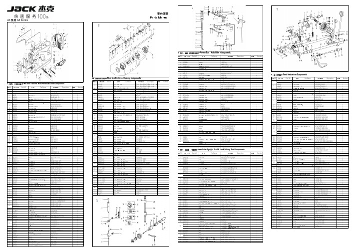
5零件手册Parts ManualA4 系列 A4 Series14. 压料、自动抬压脚分组件/Presser Presser Bar Bar ,Auto Auto Lifter Lifter Components公司件号 Part NO.名称 PartName零件描述 Description压脚扳手螺钉SM9/64"x40 L=11Screw SM9/64"x40 L=11压脚扳手螺钉垫圈Washer 压脚扳手Hand lifter O 型圈Rubber ring 压脚扳手凸轮分部件Hand lifter cam asm.前杠杆螺纹销Screw 螺纹销橡胶垫圈(厚)Washer (H )抬压脚前杠杆分部件Lift front lever component 抬压脚拉杆Knee lifter pull rod 5. 送料分组件/Feed Feed Mechanism Mechanism ComponentsGB/T896-1986挡圈 5Snap ring Main Shaft & Thread Take-up Components压脚升降板Lifting plate序号NO.公司件号 Part NO.名称 PartName零件描述 Description数量 Number抬压脚拉杆螺钉SM3/16"x32Hinge Screw SM3/16"x32Part NO.名称 PartName零件描述 Description后杠杆轴位螺钉SM15/64"x28Hinge screw SM15/64"x28111405015倒送料连杆Reverse feed connecting rod 11. 机壳、外装分组件/Machine Frame & Miscellaneous Cover Components抬压脚后杠杆Knee lifter back lever 11305015倒送料连杆(-7)Reverse feed connecting rod(-7)1挑线连杆销 (厚料)Thread take-up connecting rod pin (抬压脚顶杆Knee lifter connecting rod 211426021倒送料连杆销Connecting rod pin 1公司件号 Part NO.名称 PartName零件描述 Description挑线连杆销Thread take-up connecting rod pin 松线导管上支架Wire release bracket upper 11326011倒送料连杆销(-7)Connecting rod pin(-7)1上轮螺钉 SM15/64"x28 L=15Screw SM15/64"x28 L=15松线导管压板Wire release press plate 3101S11005螺钉 SM9/64"x40 L=6Screw SM9/64"x40 L=66101S11001后窗板螺钉SM3/16"×28 L=9Screw SM3/16"×28 L=9挑线连杆(厚料)Thread take-up connecting rod (H)油管压板螺钉SM3/16"x28 L=7Screw SM3/16"x28 L=7410101053送料调节器Feed regulator 110122003面板调节孔螺塞Rubber plug 挑线连杆Thread take-up connecting rod 松线导管压板螺钉M4x8Screw M4x8511403043送料调节器轴套Feed regulator bushing 113837002商标牌Head card GB/T896-1986挡圈Snap ring 抬压脚前杠杆组件Knee lifter lever asm 6101S11023送料调节器轴端螺钉SM3/16"x28 L=6.5Screw SM3/16"x28 L=6.51302591面板(喷漆)Face plate asm 垫片washer713826005标盘螺柱Feed regulator stud 113813005左线钩Thread guide left 针杆曲柄护板Needle bar crank protecting plate 810122016送料调节螺钉O形圈Rubber ring 1101S11007右线钩螺钉SM11/64"×40 L=6Screw SM11/64"×40 L=6挑线杆分组件Thread take-up lever asm.913811008固定表盘Fixing dial plate 113822006面板垫Face plate gasket 挑线杆组件(厚料)Thread take-up lever asm.(H )13811008固定表盘(-7)Fixing dial plate(-7)1101S11027防油板螺钉SM1/8"×44 L=3.4Screw SM1/8"×44 L=3.4挑线杆滚针轴承Needle bearing 13811013固定表盘(H-M )Fixing dial plate(H-M)110412007面部防油板Face oil shield asm.挑线曲柄分部件Thread take-up crank 10H05018GB/T896-1986挡圈3.5Snap ring 3.5111412082面部防油板(厚料)Face oil shield asm.(H)挑线曲柄分部件(厚料)Thread take-up crank (H )1113811009标盘按钮Dial plate button 110122013针杆上衬套孔塞Rubber plug 挑线曲柄分部件(H-M )Thread take-up crank (H-M )1213827002按钮复位簧Spring110122005挑线连杆销螺孔塞Rubber plug 针杆连杆Needle bar connecting rod 1313812010上限位片Upper limit patch 110122004针杆曲柄螺孔塞Rubber plug挑线曲柄螺钉(左旋)Screw141381100700标盘旋钮组件Knob component 1101S11004挑线杆护罩螺钉SM3/16"×28 L=7Screw SM3/16"×28 L=7针杆曲柄紧固螺钉 SM9/32"x28 L=16Screw SM9/32"x28 L=1615101S11022送料距旋钮螺钉SM3/16"x28 L=18Screw SM3/16"x28 L=181********挑线杆防护罩Thread take-up lever cover 针杆曲柄定位螺钉SM9/32"x28 L=16Screw SM9/32"x28 L=16101S11004挑线杆护罩螺钉SM3/16"×28 L=7Screw SM3/16"×28 L=7针杆曲柄Needle bar crank 13512004三孔线勾3-hole thread guide 针杆曲柄(厚料)Needle bar crank (H )10122005挑线连杆销螺孔塞Rubber plug送料轴挡圈螺钉SM1/4"x40 L=6Screw SM1/4"x40 L=6114S11015割线刀螺钉SM9/64"×40 L=6Screw SM9/64"×40 L=6上轴前轴套组件Main shaft bushing front 11419001割线刀Knife 夹线器螺钉SM15/64"x28 L=7Screw SM15/64"x28 L=720722002油塞Rubber plug 主轴中轴套Main shaft bushing mid 13822001操作屏孔塞Rubber plug 上轴中套挡圈螺钉Screw13822007后窗板垫Side plate gasket 上轴挡圈Main shaft thrust collar 302592后窗板(喷漆)Side plate挡圈20Snap ring 20101S11001后窗板螺钉SM3/16"×28 L=9Screw SM3/16"×28 L=9送料偏心轮 Feed eccentric cam 13811031一体机电控罩壳(鲍麦克斯)Electronic control box 送料偏心轮(厚料)Feed eccentric cam (H)W01009GB/T97.1-1985垫圈 5Washer 5送料偏心轮(H-M)Feed eccentric cam (H-M)114S13001直驱电机螺钉M5×20Screw M5×20送料偏心轮盖板Cover plate 114S30001螺栓(内六角)M5×25Screw M5×25送料偏心轮盖板(H-M)Cover plate(H-M)13833010一体机电控组件(琦星)Electronic control box(Q)送料偏心轮螺钉 SM1/4"x40 L=13Screw SM1/4"x40 L=1313833013一体机电控组件(鲍麦克斯)Electronic control box 护针片螺钉 SM9/64"x40 L=5Screw SM9/64"x40 L=510122006送料调节器孔塞Rubber plug 上轴后轴套The rear axle sleeve 10122007下轴工艺孔塞Rubber plug 上轴后套挡油油封Oil seal 138S05001操作面板螺钉ScrewGB/T894.1-1986挡圈15Snap ring 1513833012一体机电控面板组件(琦星)Control panel(Q)上轴Main shaft 13833015一体机电控面板组件(鲍麦克斯)Control panel 手轮贴条Handwheel lable 101S12001底板支柱Machine head stud 螺钉Screw 13822002装饰条Decorative article 手轮(喷漆)Handwheel 101S11004螺钉Screw电机罩壳组件(配琦星)Motor cover asm(Q)1381300400小夹线器组件Thread tension asm.电机罩壳组件(配鲍麦克斯)Motor cover asm138S16019小夹线器螺母Thread tension nut 电机光栅组件(配鲍麦)Motor grating sensor asm 11227001小夹线弹簧Thread tension spring6`12. 机头附件(1)-线架组件/Machine Head Accessories(1)-Thread Stand Components公司件号 Part NO.名称 PartName零件描述 Description8. 润滑、油量检测组件/Oil Oil Lublication 、Oil Oil Measuring Measuring Components20131019线架杆顶防护橡皮Spool rest rod rubber cap 公司件号 Part NO.名称 PartName零件描述 Description数量 S04050 十字槽凹穴六角头螺栓 M5 L=16 Screw M5 L=16 W01047垫圈M5Washer M5油窗Oil sight window N01034 螺母 M5Nut M510122019油窗O形圈Rubber ring 13831022上线架过线杆 Spool rest arm upper 上轴供油管Main shaft oil tube 10113011过线圈(内)Thread guide ring 112S30005油泵连接螺柱Oil pump connecting stud 10113010过线圈(外) Thread guide ring 11329010开口挡圈10Snap ring 1013831019线架杆上节Spool rest rod upper 6. 切线装置部件/Thread Trimmer Components供油管Hook oil tube13831021线架杆接头 Spool rest rod joint 10112020油泵安装板Oil pump installing base 13831020线架杆下节Spool rest rod lower 序号NO.公司件号 Part NO.名称 PartName零件描述 Description数量 NumberW03002弹垫Spring washer10122106橡胶垫圈Spool rest rod rubber ring 209S12001压脚螺钉SM11/64"×40 L=10.5Screw SM11/64"×40 L=10.5W01048垫圈M16Washer M161113S15002定刀调节螺钉SM1/8"x44 L=9.5Screw SM1/8"x44 L=9.5110103022油泵体衬套Oil pump bushing N02008六角薄螺母 M16Spool rest rod nut M16211319001定刀Secant knife 1101S30007柱塞螺钉Plunger Screw 10. 绕线器组件/ Bobbin ComponentsS04051十字槽凹穴六角头螺栓 M5Spool rest arm lower screw M53113S17001螺钉SM9/64"x40Screw SM9/64"x40110127013柱塞簧Plunger spring N01034 螺母 M5Nut M5411312003护针片Needle guard patch 110122018回油柱塞Plunger 公司件号 Part NO.名称 PartName零件描述 Description数量 W03002弹簧垫圈 5Spring washer 55201S11009螺钉SM9/64"x40 L=5.5Screw SM9/64"x40 L=5.5110120001油泵体Oil pump 6113S11001螺钉SM11/64"x40 L=12Screw SM11/64"x40 L=122油泵螺钉Screw1383103900绕线器组件Bobbin winder asm.油泵叶轮Oil pump impeller 114S11008螺钉M4x6Screw M4x6油泵叶轮托板Oil pump impeller cover GB/T97.1 垫圈4Washer油泵盖Lubricating oil pump cover 10113030压线控制板Thread press control plate 101S30006螺钉Screw10111120绕线衬垫Winding pad 1012000100油泵分部件Lubricating oil pump component 13831101绕线器装置主座Bobbin winder bed116S30003抬牙叉固定螺钉SM15/64"×28 L=14.5Screw SM15/64"×28 L=14.5GB/T 896-1986 开口挡圈5Snap ring 10136001供油管接头Rubber joint 10127061复位板拉簧Spring13812110调节板Regulating plate 10110030绕线凸轮Bobbin winder cam S09045螺钉Screw1380510600绕线器连杆组件Bobbin winder connecting rod 13827103满线复位簧spring 10127060弹簧Spring GB/T 896-1986开口挡圈4Snap ring13802111绕线器主轴Bobbin winder mian shaft 13802026绕线凸轮轴Bobbin winder cam shaft S09103绕线轮螺钉Screw13831102绕线轮Bobbin winder wheel O01110O 型圈Ring 11422062密封垫Washer114S11003螺钉SM3/16"×28 L=10Screw SM3/16"×28 L=101381300600底线夹线器Bobbin thread tension asm.13811004夹线螺母Thread tension nut 11427006小夹线弹簧Spring10112005夹线板Thread tension disk 11413022夹线过线板Thread tension guide plate 112S13004夹线螺钉Screw114S16001螺母SM11/64"×40Nut SM11/64"×4012. 机头附件(2)/Machine Head Accessories(2)公司件号 Part NO.名称 PartName零件描述 Description数量 1011203100机头连接钩部件 Hinge component10122060机头连接钩座 Head connecting rubber cushion 10117021机针(14#)Needle (14#)10117022机针DP×5#21(厚料)Needle (H)101S30010 机头连接钩座钉 Nail 10118003梭心 Bobbin机头支柱 Machine head rest pin 20731047螺丝刀(大)Screw driver10131003螺丝刀(中) Screw driver,medium9. 自动倒送料开关、感应抬压脚组件/Automatic Automatic Reverse Reverse Feed Feed ComponentsNO.公司件号 Part NO.名称 PartName零件描述 Description数量 NumberS05254GB/T70.1-2000螺钉M2.5×4Screw M2.5×411383004600下感应探头Lower sensor1201S11012螺钉SM9/64"×40 L=7.7Screw SM9/64"×40 L=7.7113813022过线压板Screw M4x8113822030橡皮塞(单孔)Rubber plug1101S11004挑线杆护罩螺钉SM3/16"×28 L=7Screw SM3/16"×28 L=711403003600双开关组件Auto reverse feed switch asm 1116S30003抬牙叉固定螺钉SM15/64"×28 L=14.5Screw SM15/64"×28 L=14.52W02004GB/T93-1987弹垫M6Spring washer M621011628005抬牙叉固定螺钉垫圈Washer2杰克缝纫机股份有限公司杰克缝纫机全球销量遥遥领先1383003400自动倒送料电磁铁Auto reverse feed solenoid 111. 油盘、膝抬压脚分组件/Oil Ceservoir,Knee Lifter Components1383003500自动倒送料电磁铁(-7)Auto reverse feed solenoid(-7)11211326005销子Pin 1序号NO.公司件号 Part NO.名称 PartName零件描述 Description数量 Number110122022油盘座垫Oil reservoir rubber cushion 1213801020油盘Oil Reservoir 1公司地址(Address of Company):310111005抬压脚顶杆Knee lifter push rod 1台州市椒江区机场南路15号410122020油盘垫Oil Reservoir gasket 1No.15 Rd Airport South,Jiaojiang District Taizhou City,Zhejiang,P.R.C 7. 自动抬压脚组件/Auto Lifter Components510122021O 型圈Rubber ring1邮编( Zip Code ):3180006101S11028排油孔螺钉SM5/16"×24 L=7Screw SM5/16"×24 L=72国内销售部(Domestic Trade Department):Part NO.名称 PartName零件描述 710131001油盘磁铁Oil reservoir magnet 1电话(TEL):0086-0576-******** 88177789810122023油盘支架Oil reservoir rubber cushion 1传真(FAX):0086-0576-********销子Pin 910112027抬压脚双向曲柄Knee lifter crank 1国贸部(International Trade Department):开口销 GB/T91 2×14Cotter pin电话(TEL):0086-0576-******** 88177774电磁铁接头Solenoid connector 传真(FAX):0086-0576-********法兰螺母M8Flange nuts M8服务热线:400-8876858电磁铁组件Solenoid asm.2018.12后窗板螺钉SM3/16"×28 L=9screw SM3/16"×28 L=9资料如有更改,恕不另行通知,以实物为准。
海南迅捷1U系列纤薄式水化磁闸产品简介说明书

SL1005C2BTA1SL1010C2BTA1SL1040C2BT SL1045C3BTA1SL1050C2BTA1 SL1020C2BTA1SL1035C2BTA1SL1040C2BTA2Increase Your Power DensityWith Eaton’s new Heinemann 1U Series Slimline Hydraulic Magnetic Circuit Breaker you can increase your power density without sacrificing performance. The 1U Series Slimline offers the precision performance of a full size hydraulic magnetic breaker in a miniaturized package.Designed specifically for rack-mount applications,the Slimline's reduced height is ideal for tight spaces and the protection of the latest 1U devices.The 1U Series Slimline is the first hydraulic magnetic breaker to use a snap action mecha-nism which improves reliability,safety and performance. With snap action, the contacts are controlled by a stored energy mechanism that closes in one swift action when the operator switches the handle to the ON position. This advanceddesign prevents premature contact failure, improvesefficiency and allows for higher current ratings.The 1U Series Slimline com-pact size allows greater design flexibility and saves valuablerack space without sacrificing performance. All configurations are UL ா489 listed for branch circuit protection and conform to IEC standards. Available with an integral auxiliary switch, the breaker allows for integration into the most complex systems.Take your equipment to a new level of power density and protection, never before possible. Learn about how the new Eaton 1U Series Slimline is revolutionizing the dc power protection market today.1U Series Slimline Product Highlights•Proven reliability of the Heinemann Hydraulic Magnetic Trip Unit.•Patented snap action technology for improved performance and reliability.•World’s first circuit breaker designed for 1U height rack-mount applications.•Ambient compensating trip unit from -40˚ to +80˚C.•1.0 – 100 ampere continuous current ratings (100% rated).•80 Vdc rating.•UL 489 listed.•CE mark. •Integral auxiliary switch option.•Bullet, screw or stud terminals.•Panel removal tool.•Standard distribution panel configurations available.Eaton Electrical Inc.1000 Cherrington Parkway Moon Township, PA 15108United Statestel: 1-800-525-2000© 2006 Eaton Corporation All Rights Reserved Printed in USAPublication No. PA01106001E / Z4344April 2006UL is a federally registered trademark of Underwriters Laboratories Inc. Heinemann is a federally registered trademark of Eaton Corporation.Typical DimensionsPERFORMANCE DATACurrent Range 1 – 100 A 1Continuous (100% Rated)VoltageUp to 80 Vdc or up to 240 Vac 1Interruption Rating 10 kA @ 80 Vdc 1or 10 kA @ 240 Vac 1Delay Curves Medium, Short, Instantaneous Operating Temperature -40 to + 80ºCTerminals Screw, Stud or Bullet ApprovalsUL 489 Listed, CE MarkAuxiliary Switch Rating 100 mA @ 80 Vdc or 300 mA @ 30 Vdc1Phase I Launch 5 – 60 A, 80 Vdc, 5 kA, UL 489. Consult Customer Service for availability of future releases.Catalog Number Configuration GuideUse the table below to select the correct standard catalog number for your application. Standard configuration consists of Series Trip,Imperial Mounting Inserts, UL 489 Listing and Screw Terminals. We also offer custom configurations and assembled DC distribution panels. To get additional technical assistance or for more information about custom applications, call +1 800 356 1243 (Americas), +41 21 841 92 11 (EMEA) or +86 512 6716 3397 (Asia).Auxiliary Switch OptionCATALOG NUMBERING SYSTEMNote:Catalog number example — SL1005C2.2Phase I Launch 5 – 60 A, 80 Vdc, 5 kA, UL 489. Consult Customer Service for availability of future releases.3No catalog designation is required for a standard catalog configuration.SL1005C2BTA1SL1010C2BTA1SL1040C2BT SL1045C3BTA1SL1050C2BTA1 SL1020C2BTA1SL1035C2BTA1SL1040C2BTA2。
和谐XPS安全自动化产品数据表说明书
Product data sheetSpecificationsEstop or guard ,Harmony XPS,connected to supply terminals 24 V AC/DC , no inputs, screwXPSBAC14APMainRange of ProductHarmony Safety Automation Product or Component Type Safety module Safety module name XPSBACSafety module application For emergency stop and protective guard applications Function of module Emergency stop button with 2 NC contacts Guard monitoring with 1 or 2 limit switchesSafety levelCan reach PL e/category 4 for normally open relay contact ISO 13849-1Can reach SILCL 3 for normally open relay contact IEC 62061Can reach SIL 3 for normally open relay contact IEC 61508Can reach PL c/category 1 for normally closed relay contact ISO 13849-1Can reach SILCL 1 for normally closed relay contact IEC 62061Can reach SIL 1 for normally closed relay contact IEC 61508Safety reliability dataMTTFd > 30 years for normally open relay contact ISO 13849-1Dcavg >= 99 % for normally open relay contact ISO 13849-1PFHd = 0.95E-09 for normally open relay contact ISO 13849-1HFT = 1 for normally open relay contact IEC 62061PFHd = 0.95E-09 for normally open relay contact IEC 62061SFF > 99% for normally open relay contact IEC 62061HFT = 1 for normally open relay contact IEC 61508-1PFHd = 0.95E-09 for normally open relay contact IEC 61508-1SFF > 99% for normally open relay contact IEC 61508-1Type = B for normally open relay contact IEC 61508-1MTTFd > 30 years for normally closed relay contact ISO 13849-1DC > 60 % for normally closed relay contact ISO 13849-1PFHd = 0.95E-09 for normally closed relay contact ISO 13849-1HFT=0 for normally closed relay contact IEC 62061PFHd = 0.95E-09 for normally closed relay contact IEC 62061SFF > 60% for normally closed relay contact IEC 62061HFT=0 for normally closed relay contact IEC 61508-1PFHd = 0.95E-09 for normally closed relay contact IEC 61508-1SFF > 60% for normally closed relay contact IEC 61508-1Type = B for normally closed relay contact IEC 61508-1Electrical circuit type NC pairConnections - terminalsRemovable screw terminal block, 0.2...2.5 mm² solid or flexibleRemovable screw terminal block, 0.25...2.5 mm² flexible with ferrule single conductor Removable screw terminal block, 0.2...1.5 mm² solid or flexible twin conductorRemovable screw terminal block, 2 x 0.25...1 mm² flexible with ferrule without cable end, with bezel Removable screw terminal block, 2 x 0.5...1.5 mm² flexible with ferrule with cable end, with bezel [Us] Rated Supply Voltage24 V AC - 15...10 %24 V DC - 20...20 %ComplementarySynchronisation time between inputs UnlimitedType of startAutomatic/manual/monitoredD i s c l a i m e r : T h i s d o c u m e n t a t i o n i s n o t i n t e n d e d a s a s u b s t i t u t e f o r a n d i s n o t t o b e u s e d f o r d e t e r m i n i n g s u i t a b i l i t y o r r e l i a b i l i t y o f t h e s e p r o d u c t s f o r s p e c i f i c u s e r a p p l i c a t i o n sPower consumption in W 1.5 W 24 V DCPower consumption in VA 3.5 VA 24 V AC 50/60 HzInput protection type Internal, electronicSafety outputs 4 NO + 1 NCSafety inputs0Input compatibility Normally closed circuit ISO 14119XC limit switch ISO 14119Mechanical contact ISO 14119Normally closed circuit ISO 13850Input terminal Power supply[Ie] rated operational current5 A AC-13 A AC-155 A DC-13 A DC-133 A AC-11 A AC-153 A DC-11 A DC-13Control outputs0[Ith] conventional free air6 Athermal currentAssociated fuse rating10 A gG NO relay output circuit IEC 60947-1 Minimum output current10 mA relay outputMinimum output voltage5 V relay outputResponse time150 ms at 24 V AC80 ms at 24 V DC[Ui] rated insulation voltage300 V 2)EN/IEC 60947-1[Uimp] rated impulse withstand4 kV II EN/IEC 60947-1voltageLocal signalling LED green power power ONLED red error errorLED yellow state statusLED yellow start1 start inputLED yellow start2 start inputMounting Support35 mm symmetrical DIN railDepth 4.72 in (120 mm)Height 3.94 in (100 mm)Width0.89 in (22.5 mm)Net Weight0.44 lb(US) (0.200 kg) EnvironmentAmbient Air Temperature for-13…131 °F (-25…55 °C)OperationStandards IEC 60947-5-1IEC 61508-1 functional safety standardIEC 61508-2 functional safety standardIEC 61508-3 functional safety standardIEC 61508-4 functional safety standardIEC 61508-5 functional safety standardIEC 61508-6 functional safety standardIEC 61508-7 functional safety standardISO 13849-1 functional safety standardIEC 62061 functional safety standardProduct certifications TÜVcULusIP degree of protection IP20 terminals)EN/IEC 60529IP40 housing)EN/IEC 60529IP54 mounting area)EN/IEC 60529 Relative Humidity5…95 % non-condensingOrdering and shipping detailsCategory22477-SAFETY MODULES (PREVENTA)Discount Schedule SAF2GTIN3606482034013Nbr. of units in pkg.1Package weight(Lbs)10.76 oz (305 g)Returnability YesPacking UnitsUnit Type of Package 1PCEPackage 1 Height 2.52 in (6.4 cm)Package 1 width 5.24 in (13.3 cm)Package 1 Length 6.02 in (15.3 cm)Unit Type of Package 2S03Number of Units in Package 216Package 2 Weight12.01 lb(US) (5.448 kg)Package 2 Height11.81 in (30 cm)Package 2 width11.81 in (30 cm)Package 2 Length15.75 in (40 cm)Package 3 Height11.81 in (30 cm)Offer SustainabilitySustainable offer status Green Premium productCalifornia proposition 65WARNING: This product can expose you to chemicals including: Lead and lead compounds, which isknown to the State of California to cause cancer and birth defects or other reproductive harm. For moreinformation go to REACh Regulation REACh DeclarationEU RoHS Directive Pro-active compliance (Product out of EU RoHS legal scope)EU RoHS DeclarationMercury free YesRoHS exemption information YesChina RoHS Regulation China RoHS declarationEnvironmental Disclosure Product Environmental ProfileCircularity Profile End of Life InformationWEEE The product must be disposed on European Union markets following specific waste collection andnever end up in rubbish bins.Dimensions Drawings DimensionsFront and Side Views(A) : Product drawing(B) : Screw clamp terminal(C) : Side view(1) : Removable terminal blocks, top(2) : Removable terminal blocks, bottom(3) : LED indicators(4) : Sealable transparent coverMounting to DIN railScrew-mountingConnections and SchemaWiring Diagram(1) : A1-A2 (Power supply)(2) : Y1 (Control output of Start/Restart input), Y2 (Input channel for automatic/manual start/restart), Y3 (Input channel for monitored start/restart with falling edge)13-14-23-24-33-34-43-44-51/61-52-62 : Terminals of the safety-related outputs。
maxim MAX811 MAX812 datasheet说明书

General DescriptionThe MAX811/MAX812 are low-power microprocessor (μP) supervisory circuits used to monitor power supplies in μP and digital systems. They provide excellent circuit reliability and low cost by eliminating external compo-nents and adjustments when used with 5Vpowered or 3V-powered circuits. The MAX811/MAX812 also provide a debounced manual reset input.These devices perform a single function: They assert a reset signal whenever the V CC supply voltage falls below a preset threshold, keeping it asserted for at least 140ms after V CC has risen above the reset threshold. The only difference between the two devices is that the MAX811 has an active-low RESET output (which is guaranteed to be in the correct state for V CC down to 1V), while the MAX812 has an active-high RESET output. The reset comparator is designed to ignore fast transients on V CC. Reset thresholds are available for operation with a variety of supply voltages.Low supply current makes the MAX811/MAX812 ideal for use in portable equipment. The devices come in a 4-pin SOT143 package.Applications●Computers●Controllers●Intelligent Instruments●Critical μP and μC Power Monitoring●Portable/Battery-Powered Equipment Benefits and Features●Integrated Voltage Monitor Increases SystemRobustness with Added Manual Reset• Precision Monitoring of 3V, 3.3V, and 5VPower-Supply Voltages• 140ms Min Power-On-Reset Pulse Width• RESET Output (MAX811), RESET Output(MAX812)• Guaranteed Over Temperature• Guaranteed RESET Valid to V CC = 1V (MAX811)• Power-Supply Transient Immunity●Saves Board Space• No External Components• 4-Pin SOT143 Package●Low Power Consumption Simplifies Power-SupplyRequirements• 6μA Supply Current*This part offers a choice of five different reset threshold voltages. Select the letter corresponding to the desired nominal reset threshold voltage, and insert it into the blank to complete the part number.Devices are available in both leaded and lead(Pb)-free packaging. Specify lead-free by replacing “-T” with “+T” when ordering.RESET THRESHOLDSUFFIX VOLTAGE (V)L 4.63M 4.38T 3.08S 2.93R2.63PART*TEMP RANGE PIN-PACKAGEMAX811_EUS-T-40°C to +85°C 4 SOT143MAX812_EUS-T-40°C to +85°C 4 SOT1431243V CCMR(RESET) RESETGNDMAX811MAX812SOT143TOP VIEW( ) ARE FOR MAX812NOTE: SEE PACKAGE INFORMATION FOR MARKING INFORMATION. MAX811/MAX8124-Pin μP Voltage Monitorswith Manual Reset InputPin ConfigurationOrdering InformationClick here for production status of specific part numbers.19-0411; Rev 6; 5/18Terminal Voltage (with respect to GND)V CC.....................................................................-0.3V to 6.0V All Other Inputs .....................................-0.3V to (V CC + 0.3V) Input Current, V CC, MR......................................................20mA Output Current, RESET or RESET ....................................20mA Continuous Power Dissipation (T A = +70°C)SOT143 (derate 4mW/°C above +70°C) .....................320mW Operating Temperature Range ...........................-40°C to +85°C Junction Temperature ......................................................+150°C Storage Temperature Range ............................-65°C to +160°C Lead Temperature (soldering, 10sec) .............................+300°C(V CC = 5V for L/M versions, V CC = 3.3V for T/S versions, V CC = 3V for R version, T A = -40°C to +85°C, unless otherwise noted. Typical values are at T A = +25°C.) (Note 1)PARAMETER SYMBOL CONDITIONS MIN TYP MAX UNITSOperating Voltage Range V CC T A = 0°C to +70°C 1.0 5.5V T A = -40°C to +85°C 1.2Supply Current I CC MAX81_L/M, V CC = 5.5V, I OUT = 0615µA MAX81_R/S/T, V CC = 3.6V, I OUT = 0 2.710Reset Threshold V TH MAX81_LT A = +25°C 4.54 4.63 4.72V T A = -40°C to +85°C 4.50 4.75MAX81_MT A = +25°C 4.30 4.38 4.46T A = -40°C to +85°C 4.25 4.50MAX81_TT A = +25°C 3.03 3.08 3.14T A = -40°C to +85°C 3.00 3.15MAX81_ST A = +25°C 2.88 2.93 2.98T A = -40°C to +85°C 2.85 3.00MAX81_RT A = +25°C 2.58 2.63 2.68T A = -40°C to +85°C 2.55 2.70Reset Threshold Tempco30ppm/°CV CC to Reset Delay (Note 2)V OD = 125mV, MAX81_L/M40µs V OD = 125mV, MAX81_R/S/T20Reset Active Timeout Period t RP V CC = V TH(MAX)140560ms MR Minimum Pulse Width t MR10µs MR Glitch Immunity (Note 3)100ns MR to Reset PropagationDelay (Note 2)t MD0.5µsMR Input Threshold V IHV CC > V TH(MAX), MAX81_L/M2.3V V IL0.8V IHV CC > V TH(MAX), MAX81_R/S/T0.7 x V CCV IL0.25 x V CCMR Pull-Up Resistance102030kΩRESET Output Voltage (MAX812)V OH I SOURCE = 150µA, 1.8V < V CC < V TH(MIN)0.8 x V CCVV OLMAX812R/S/T only, I SINK = 1.2mA,V CC = V TH(MAX)0.3MAX812L/M only, I SINK = 3.2mA,V CC = V TH(MAX)0.4with Manual Reset InputAbsolute Maximum RatingsStresses beyond those listed under “Absolute Maximum Ratings” may cause permanent damage to the device. These are stress ratings only, and functional operation of the device at these or any other conditions beyond those indicated in the operational sections of the specifications is not implied. Exposure to absolute maximum rating conditions for extended periods may affect device reliability.Electrical Characteristics(V CC = 5V for L/M versions, V CC = 3.3V for T/S versions, V CC = 3V for R version, T A = -40°C to +85°C, unless otherwise noted.Typical values are at T A = +25°C.) (Note 1)Note 1: Production testing done at T A = +25°C, over temperature limits guaranteed by design using six sigma design limits.Note 2: RESET output for MAX811, RESET output for MAX812.Note 3: “Glitches” of 100ns or less typically will not generate a reset pulse.PARAMETERSYMBOLCONDITIONSMINTYPMAX UNITSRESET Output Voltage (MAX811)V OLMAX811R/S/T only, I SINK = 1.2mA, V CC = V TH(MIN)0.3V MAX811L/M only, I SINK = 3.2mA, V CC = V TH(MIN)0.4I SINK = 50µA, V CC > 1.0V0.3V OHMAX811R/S/T only, I SOURCE = 500µA, V CC > V TH(MAX)0.8 x V CC MAX811L/M only, I SOURCE = 800µA, V CC > V TH(MAX)V CC - 1.5with Manual Reset InputElectrical Characteristics (continued)(T A = +25°C, unless otherwise noted.)SUPPLY CURRENT vs. TEMPERATURE(MAX81_L/M)8TEMPERATURE (°C)S U P P L Y C U R R E N T (µA )426-408510-156035190POWER-UP RESET TIMEOUTvs. TEMPERATURE230TEMPERATURE (°C)P O W E R -U P R E S E T T I M E O U T (m s )210200220-408535-1510600POWER-DOWN RESET DELAY vs. TEMPERATURE(MAX81_R/S/T)80100TEMPERATURE (°C)P O W E R -D O W N R E S E T D E L A Y (µs )402060-408510-156035RESET THRESHOLD DEVIATIONvs. TEMPERATURE0.99951.00001.0005M A X 811/12-T O C 6TEMPERATURE (°C)N O R M A L I Z E D T H R E S H O L D (V )0.99850.99800.9990-408535-1510600-4085SUPPLY CURRENT vs. TEMPERATURE(MAX81_R/S/T)2.02.53.0M A X 811/12-T O C 1TEMPERATURE (°C)S U P P L Y C U R R E N T (µA )101.00.5-15601.535POWER-DOWN RESET DELAY vs. TEMPERATURE(MAX81_L/M)200TEMPERATURE (°C)P O W E R -D O W N R E S E T D E L A Y (µs )10050150-408510-156035with Manual Reset InputTypical Operating CharacteristicsDetailed DescriptionReset OutputA microprocessor’s (μP’s) reset input starts the μP in a known state. These μP supervisory circuits assert reset to prevent code execution errors during power-up, power-down, or brownout conditions.RESET is guaranteed to be a logic low for V CC> 1V. Once V CC exceeds the reset threshold, an internal timer keeps RESET low for the reset timeout period; after this interval, RESET goes high.If a brownout condition occurs (V CC dips below the reset threshold), RESET goes low. Any time V CC goes below the reset threshold, the internal timer resets to zero, and RESET goes low. The internal timer starts after V CC returns above the reset threshold, and RESET remains low for the reset timeout period.The manual reset input (MR) can also initiate a reset. See the Manual Reset Input section.The MAX812 has an active-high RESET output that is the inverse of the MAX811’s RESET output.Manual Reset InputMany μP-based products require manual reset capabil-ity, allowing the operator, a test technician, or external logic circuitry to initiate a reset. A logic low on MR asserts reset. Reset remains asserted while MR is low, and for the Reset Active Timeout Period (t RP) after MR returns high. This input has an internal 20kΩ pull-up resistor, so it can be left open if it is not used. MR can be driven with TTL or CMOS-logic levels, or with open-drain/collector outputs. Connect a normally open momentary switch from MR to GND to create a manual-reset function; external debounce circuitry is not required. If MR is driven from long cables or if the device is used in a noisy environment, connecting a 0.1μF capacitor from MR to ground provides additional noise immunity.Reset Threshold AccuracyThe MAX811/MAX812 are ideal for systems using a 5V ±5% or 3V ±5% power supply with ICs specified for 5V ±10% or 3V ±10%, respectively. They are designed to meet worst-case specifications over temperature. The reset is guaranteed to assert after the power supply falls out of regulation, but before power drops below the minimum specified operating voltage range for the system ICs. The thresholds are pre-trimmed and exhibit tight dis-tribution, reducing the range over which an undesirable reset may occur.PINNAME FUNCTION MAX811MAX81211GND Ground2—RESET Active-Low Reset Output. RESET remains low while V CC is below the reset threshold or while MR is held low. RESET remains low for the Reset Active Timeout Period (t RP) after the reset conditions are terminated.—2RESET Active-High Reset Output. RESET remains high while V CC is below the reset threshold or while MR is held low. RESET remains high for Reset Active Timeout Period (t RP) after the reset conditions are terminated.33MR Manual Reset Input. A logic low on MR asserts reset. Reset remains asserted as long as MR is low and for 180ms after MR returns high. This active-low input has an internal 20kΩpull-up resistor. It can be driven from a TTL or CMOS-logic line, or shorted to ground with a switch. Leave open if unused.44V CC+5V, +3.3V, or +3V Supply Voltage with Manual Reset InputPin DescriptionApplications InformationNegative-Going V CC TransientsIn addition to issuing a reset to the μP during power-up, power-down, and brownout conditions, the MAX811/ MAX812 are relatively immune to short duration negative-going V CC transients (glitches).Figure 1 shows typical transient durations vs. reset com-parator overdrive, for which the MAX811/MAX812 do not generate a reset pulse. This graph was generated using a negative-going pulse applied to V CC, starting above the actual reset threshold and ending below it by the magnitude indicated (reset comparator overdrive). The graph indicates the typical maximum pulse width a negative-going V CC transient may have without causing a reset pulse to be issued. As the magnitude of the tran-sient increases (goes farther below the reset threshold), the maximum allowable pulse width decreases. Typically, a V CC transient that goes 125mV below the reset thresh-old and lasts 40μs or less (MAX81_L/M) or 20μs or less (MAX81_T/S/R) will not cause a reset pulse to be issued.A 0.1μF capacitor mounted as close as possible to V CC provides additional transient immunity.Ensuring a Valid RESET OutputDown to V CC = 0VWhen V CC falls below 1V, the MAX811 RESET output no longer sinks current—it becomes an open circuit. Therefore, high-impedance CMOS-logic inputs connected to the RESET output can drift to undetermined voltages. This presents no problem in most applications, since most μP and other circuitry is inoperative with V CC below 1V. However, in applications where the RESET output must be valid down to 0V, adding a pulldown resistor to the RESET pin will cause any stray leakage currents to flow to ground, holding RESET low (Figure 2). R1’s value is not critical; 100kΩ is large enough not to load RESET and small enough to pull RESET to ground.A 100kΩ pull-up resistor to V CC is also recommended for the MAX812 if RESET is required to remain valid for V CC < 1V.Figure 1. Maximum Transient Duration without Causing a Reset Pulse vs. Comparator Overdrive Figure 2. RESET Valid to V CC = Ground Circuitwith Manual Reset InputInterfacing to μPs with Bidirectional Reset PinsμPs with bidirectional reset pins (such as the Motorola 68HC11 series) can contend with the MAX811/MAX812 reset outputs. If, for example, the MAX811 RESET output is asserted high and the μP wants to pull it low, indeter -minate logic levels may result. To correct such cases, connect a 4.7kΩ resistor between the MAX811 RESET (or MAX812 RESET) output and the μP reset I/O (Figure 3). Buffer the reset output to other system components.Figure 3. Interfacing to μPs with Bidirectional Reset I/Owith Manual Reset InputChip InformationTRANSISTOR COUNT: 341with Manual Reset Input Package InformationFor the latest package outline information and land patterns (footprints), go to /packages. Note that a “+”, “#”, or “-” in the package code indicates RoHS status only. Package drawings may show a different suffix character, but the drawing pertains to the package regardless of RoHS status.PACKAGE TYPE PACKAGE CODE OUTLINE ND PATTERN NO.4 SOT143U4+121-005290-0183REVISION NUMBERREVISION DATE DESCRIPTIONPAGES CHANGED56/15Updated Benefits and Features and Package Information sections 1, 865/18Updated Absolute Maximum Ratings2Maxim Integrated cannot assume responsibility for use of any circuitry other than circuitry entirely embodied in a Maxim Integrated product. No circuit patent licenses are implied. Maxim Integrated reserves the right to change the circuitry and specifications without notice at any time. The parametric values (min and max limits) shown in the Electrical Characteristics table are guaranteed. Other parametric values quoted in this data sheet are provided for guidance.with Manual Reset InputRevision HistoryFor pricing, delivery, and ordering information, please visit Maxim Integrated’s online storefront at https:///en/storefront/storefront.html.。
LRX系列材料试验机的文档说明书

LRX SERIESMaterials Testing MachineThe LRX single column, bench mounted materials testing system provides a complete solution for testing applications with capacities up to 2.5kN (550 lbf). Tension and compression testing with cycling to load and extension limits are standard features. Load and extension are displayed on a highly legible LCD display console, selectable in a variety of units. Multi-lingual instructions are displayed in a sequential menu driven format, allowing test set-up and operation to be achieved rapidly and efficiently. The extension measurement system uses a digital encoder to achieve high resolution throughout its extension ranges.The LRX can be further enhanced with Lloyd Instruments state of the art materials test and results analysis software NEXYGEN™ thanks to a supplied RS232 interface. The system is ideal for batch testing in production or routine quality control checks. Alternatively, it can be configured as a sophisticated research grade machine incorporating multi-stage testing for product development and complex research applications.FEATURESSimple to set-up, operate and maintain High accuracy load measurement Rapid data aquisitionContinuous cycling between extension and load limits Extension resolution better than 5 microns Multi lingual, Multi unit display options Full PC integrationWide selection of load cells, grips, jigs and accessoriesSPECIFICATION SS-MT-6125-0101January 2001INTERNET AMETEK , CHATILLON and NEXYGEN are registered trademarks of AMETEK, inc LLOYD INSTRUMENTS is a trademark of AMETEK, inc.Copyright 2000, by AMETEK, inc.SPECIFICATIONSForce Range: 2.5kN (550 lbf)Crosshead Speed:0.1 to 1020 mm/min 0.005 to 40 inches/min Speed Accuracy:< 0.2%Stroke (LRX) 1 to 750 mm 0.04 to 30 inches Stroke (LRX-E) 1 to 1500 mm 0.04 to 60 inchesLoad Resolution:< 0.005% of load cell used (max)Extension Resolution:< 5 microns Data Sampling Rate:40HzExtensometer Inputs:+10V dc analogue input (optional)Data Outputs:Digital - RS232Analogue - 10Vdc maxMeasuring System:Exceeds the requirements of BS EN ISO 7500:1999. Class 0.5, ASTM E4, DIN 51221.Analysis Software:NEXYGEN™ Data Analysis Software (optional)Supply Voltage:115/230Vac ± 10% 50 - 60Hz Weight:54kg (119lb)Operating Temp:5° to 35°C (40°F to 95°F)Warranty:1 year1981ORDERING INFORMATIONSTANDARD ACCESSORIESLOADCELLS:ITEM MODEL5 N (1 lbf)LRX-0005-A101/296810 N (2 lbf)LRX-0010-A101/232220 N (4 lbf)LRX-0020-A101/260050 N (11 lbf)LRX-0050-A101/2321100 N (22 lbf)LRX-0100-A101/2320250 N (55 lbf)LRX-0250-A101/2992500 N (110 lbf)LRX-0500-A101/21641000 N (220 lbf)LRX-1000-A101/21632500 N (550 lbf)LRX-2500-A101/21315000 N (1100 lbf)LRX-5000-A101/2317EXTENSOMETERS:Non Contacting Extensometer (115V) with stand LASERSCAN L101/2940Non Contacting Extensometer (230V) with stand LASERSCAN LR01/2932Extensometer Punch (applies 2 mm, 0.08 in) targets TTOXP/201/1159Extensometer Punch(applies 4 mm, 0.16 in) targets TTOXP/401/1156Longtravel Extensometer without stand EXL750 LR01/2247Extensometer Stand for EXL750EXT STAND A01/2314Strain Gauge Extensometers require special amplifierSOFTWARE:NEXYGEN™ 4.0 Software Package40/0658NEXYGEN™ Upgrade to Version 4.040/0658/NRONDIO Application Builder (Use With NEXYGEN)40/0683NEXYGEN/ONDIO Software Suite40/0695NEXYGEN/ONDIO Upgrade40/0695/UGRIPS & FIXTURES:All Lloyd Instruments grips up to a capacity of 10 kN (2200 lbf) can be fitted.TEST AND CALIBRATION INSTRUMENTSUKLloyd Instruments LtdForum House12 Barnes Wallis RdSegensworth East, FarehamHampshire, UKPO15 5TTTel: +44 (0)1489 486 399Fax: +44 (0)1489 885 118AmericaAMETEK TCI Division8600 Somerset DriveLargoFlorida 33773USATel: +1 (727) 536 7831Fax: +1(727) 539 6882Far EastLloyd InstrumentsFar East Representative OfficeNo7 Sherwood PlaceAlexander Heights6064 PerthWESTERN AUSTRALIATel: +61 8 9343 5725Fax: +61 8 9343 5723Information within this document is subject to change without notice.FranceLloyd Instruments SA3 avenue des CoudriersZone d’activite de l’observatoire78180 Montigny-Le-BretonneuxFRANCETel: +33 (1) 30 57 47 74Fax: +33 (1) 30 57 50 33GermanyAMETEK Precision InstrumentsEurope GmbHRudolf-Diesel-Straße 16D-40670 MeerbuschGERMANYTel: +49 (0)2159 9136-70Fax: +49 (0)2159 9136-80ISO 9001Manufacturer email:****************************.ukLRX DIMENSIONSColumn Depth145mm 5.7inMachine Height1258mm49.5inBase Height170mm 6.7inMachine Width564mm22.2inMachine Depth379mm14.9inConsole Width within footprint of the machineConsole Depth within footprint of the machineConsole Height within footprint of the machineColumn to eye end135mm 5.25inAll machines are capable of testing in tension, compression,flexure, friction, tear, peel, and adhesion modes - plus manymore.。
Schneider Electric XPSAK311144 产品数据手册说明书

i s c l a i m er : T h i s d o c u m e n t a t i o n i s n o t i n t e n d e d a s a s u b s t i t u t e f o r a n d i s n o t t o b e u s e d f o r d e t e r m i n i n g s u i t a b i l i t y o r r e l i a b i l i t y o f t h e s e p r o d u c t s f o r s p e c i f i c u s e r a p p l i c a t i o n sProduct data sheetCharacteristicsXPSAK311144module XPSAK - Emergency stop - 24 V AC DCProduct availability : Stock - Normally stocked in distribution facilityPrice* : 450.00 USDMainRange of productPreventa Safety automation Product or component type Preventa safety module Safety module name XPSAKSafety module application For emergency stop, switch, sensing mat/edges or safety light curtain monitoring Function of moduleMonitoring of electro-sensitive protection equipment (ESPE)Monitoring of a movable guard associated with 2 switches and automatic start Monitoring of a movable guardEmergency stop monitoring 1-channel wiringEmergency stop with 2 NC contacts monitoring 2-channel wiring Multiple emergency stop monitoring 2-channel wiring Proximity sensor monitoringSensing mat and edges monitoringSafety levelCan reach PL e/category 4 conforming to EN/ISO 13849-1Can reach SILCL 3 conforming to EN/IEC 62061Safety reliability dataDC > 99 % conforming to EN/ISO 13849-1MTTFd = 154.5 years conforming to EN/ISO 13849-1PFHd = 7.39E-9 1/h conforming to EN/IEC 62061Type of startConfigurableConnections - terminalsCaptive screw clamp terminals, clamping capacity: 2 x 0.5...2 x 1.5 mm² flexible cable with cable end,with double bezelCaptive screw clamp terminals, clamping capacity: 1 x 0.14...1 x 2.5 mm² flexible cable with cable end, with double bezelCaptive screw clamp terminals, clamping capacity: 1 x 0.14...1 x 2.5 mm² solid cable with cable end,with double bezelCaptive screw clamp terminals, clamping capacity: 1 x 0.25...1 x 1.5 mm² flexible cable with cable end, with double bezelCaptive screw clamp terminals, clamping capacity: 1 x 0.25...1 x 2.5 mm² flexible cable with cable end, with double bezelCaptive screw clamp terminals, clamping capacity: 2 x 0.14...2 x 0.75 mm² flexible cable with cable end, with double bezelCaptive screw clamp terminals, clamping capacity: 2 x 0.14...2 x 0.75 mm² solid cable with cable end,with double bezelCaptive screw clamp terminals, clamping capacity: 2 x 0.25...2 x 1 mm² flexible cable with cable end,with double bezelOutput typeRelay instantaneous opening 3 NO, volt-freeNumber of additional circuits 1 NC + 4 solid state outputs[Us] rated supply voltage24 V AC (- 15...10 %)24 V DC (- 15...10 %)ComplementarySynchronisation time between inputs 2 or 4 s depending of wiring (automatic start)Unlimited (manual start)Supply frequency50/60 HzPower consumption in VA<= 5 VA ACInput protection type Internal, electronicControl circuit voltage24 V DCLine resistance28 OhmBreaking capacity C300: 180 VA, AC-15 (holding) relay outputC300: 1800 VA, AC-15 (inrush) relay outputBreaking capacity 1.5 A at 24 V (DC-13) time constant: 50 ms for relay outputOutput thermal current 6 A per relay relay output18 A[Ith] conventional free air thermalcurrentAssociated fuse rating 4 A fuse type gG or gL for relay output conforming to EN/IEC 60947-5-1, DIN VDE 0660 part 2006 A fuse type fast blow for relay output conforming to EN/IEC 60947-5-1, DIN VDE 0660 part 200 Minimum output current10 mA relay outputMinimum output voltage17 V relay outputResponse time on input open<= 40 ms[Ui] rated insulation voltage300 V (degree of pollution: 2) conforming to DIN VDE 0110 part 1300 V (degree of pollution: 2) conforming to IEC 60947-5-1[Uimp] rated impulse withstand voltage 4 kV overvoltage category III conforming to IEC 60947-5-14 kV overvoltage category III conforming to DIN VDE 0110 part 1Local signalling 4 LEDsCurrent consumption30 mA at 24 V AC (on power supply)Mounting support35 mm symmetrical DIN railProduct weight0.66 lb(US) (0.3 kg)EnvironmentStandards EN 1088/ISO 14119EN/IEC 60204-1EN/IEC 60947-5-1EN/ISO 13850Product certifications CSATÜVULIP degree of protection IP20 (terminals) conforming to EN/IEC 60529IP40 (enclosure) conforming to EN/IEC 60529Ambient air temperature for operation14...131 °F (-10...55 °C)Ambient air temperature for storage-13...185 °F (-25...85 °C)Ordering and shipping detailsCategory22477 - SAFETY MODULES (PREVENTA)Discount Schedule SAF2GTIN00785901291664Nbr. of units in pkg.1Package weight(Lbs)0.80000000000000004Returnability YCountry of origin IDContractual warrantyWarranty period18 months。
IRFZ44规格书

This is a calculated value limited to TJ = 175°C .
2
IRFZ44N
1000
VGS 15V 10V 8.0V 7.0V 6.0V 5.5V 5.0V BOTTOM 4.5V TOP
1000
I D , Drain-to-Source Current (A)
D
S
Source-Drain Ratings and Characteristics
IS
ISM
VSD trr Qrr ton Notes:
Parameter Continuous Source Current (Body Diode) Pulsed Source Current (Body Diode) Diode Forward Voltage Reverse Recovery Time Reverse Recovery Charge Forward Turn-On Time
D
VDSS = 55V RDS(on) = 17.5mΩ
G S
ID = 49A
Description
Advanced HEXFET® Power MOSFETs from International Rectifier utilize advanced processing techniques to achieve extremely low on-resistance per silicon area. This benefit, combined with the fast switching speed and ruggedized device design that HEXFET power MOSFETs are well known for, provides the designer with an extremely efficient and reliable device for use in a wide variety of applications. The TO-220 package is universally preferred for all commercial-industrial applications at power dissipation levels to approximately 50 watts. The low thermal resistance and low package cost of the TO-220 contribute to its wide acceptance throughout the industry.