PE44353中文资料
APM4435KC-TRL中文资料
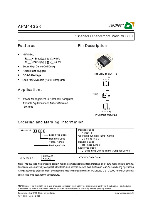
ANPEC reserves the right to make changes to improve reliability or manufacturability without notice, and advise customers to obtain the latest version of relevant information to verify before placing orders.APM4435KFeaturesApplications• Power Management in Notebook Computer,Portable Equipment and Battery Powered SystemsPin DescriptionOrdering and Marking InformationP-Channel MOSFETAPM4435Handling Code Temp. Range Package CodePackage Code K : SOP-8Operating Junction Temp. Range C : -55 to 150C Handling CodeTR : Tape & Reel Lead Free CodeL : Lead Free Device Blank : Original Device APM4435 K :XXXXX - Date CodeLead Free Code APM4435XXXXX• -30V/-8A ,RDS(ON)=16m Ω(typ.) @ VGS =-10VRDS(ON)=24m Ω(typ.) @ V GS =-4.5V• Super High Dense Cell Design • Reliable and Rugged • SOP-8 Package•Lead Free Available (RoHS Compliant)Top View of SOP − 8G(4)(1, 2, 3)(5, 6, 7, 8)Note: ANPEC lead-free products contain molding compounds/die attach materials and 100% matte in plate termina-tion finish; which are fully compliant with RoHS and compatible with both SnPb and lead-free soldiering operations.ANPEC lead-free products meet or exceed the lead-free requirements of IPC/JEDEC J STD-020C for MSL classifica-tion at lead-free peak reflow temperature.APM4435KAbsolute Maximum Ratings (TA= 25°C unless otherwise noted)Electrical Characteristics (TA = 25°C unless otherwise noted)*Surface Mounted on 1in2 pad area, t ≤ 10sec.APM4435KElectrical Characteristics (Cont.) (T= 25°C unless otherwise noted)Aa : Pulse test ; pulse width≤300µs, duty cycle≤2%.b : Guaranteed by design, not subject to production testing.APM4435K1E-41E-30.010.1110301E-30.010.112Typical Characteristics-I D - D r a i n C u r r e n t (A )Drain CurrentT j - Junction Temperature (°C)Safe Operation Area-V DS - Drain - Source Voltage (V)Thermal Transient ImpedanceSquare Wave Pulse Duration (sec)Power DissipationP t o t - P o w e r (W )T j - Junction Temperature (°C)-I D - D r a i n C u r r e n t (A )204060801001201401600.00.51.01.52.02.5204060801001201401602468100.010.11101000.010.1110100N o r m a l i z e d T r a n s i en t T h e r m a l R e s i s t a n c e012345-50-250255075100125150 -V GS - Gate - Source Voltage (V)T j - Junction Temperature (°C)APM4435K-V DS - Drain - Source Voltage (V)Drain-Source On ResistanceN o r m a l i z e dO n R e s i s t a n c e T j - Junction Temperature (°C)C - C a p a c i t a n c e (p F )-V SD - Source - Drain Voltage (V)-I S - S o u r c e C u r r e n t (A )CapacitanceGate ChargeQ G - Gate Charge (nC)-V G S - G a t e -s o u r c e V o l t a g e (V )Typical Characteristics (Cont.)-50-252550751001251500.000.250.500.751.001.251.501.752.000.1110305101520253005001000150020002500300035004000450050005101520253035404550APM4435KPackaging InformationSOP-8 pin ( Reference JEDEC Registration MS-012)APM4435KT LT P25T e m p e r a t u r eTimeReflow Condition (IR/Convection or VPR Reflow)Classification Reflow ProfilesPhysical SpecificationsAPM4435KCarrier Tape & Reel DimensionsReliability Test ProgramClassification Reflow Profiles(Cont.)APM4435KCover Tape DimensionsCarrier Tape & Reel Dimensions(Cont.)(mm)Customer ServiceAnpec Electronics Corp.Head Office :No.6, Dusing 1st Road, SBIP,Hsin-Chu, Taiwan, R.O.C.Tel : 886-3-5642000Fax : 886-3-5642050Taipei Branch :7F, No. 137, Lane 235, Pac Chiao Rd.,Hsin Tien City, Taipei Hsien, Taiwan, R. O. C.Tel : 886-2-89191368Fax : 886-2-89191369。
SI4435DDY-T1-GE3;SI4435DDY-T1-E3;中文规格书,Datasheet资料
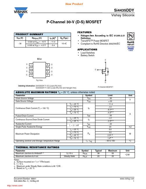
Vishay SiliconixSi4435DDYDocument Number: P-Channel 30-V (D-S) MOSFETFEATURES•Halogen-free According to IEC 61249-2-21Definition•TrenchFET ® Power MOSFET•Compliant to RoHS Directive 2002/95/ECAPPLICATIONS•Load Switches •Battery SwitchNotes:a.Surface mounted on 1" x 1" FR4 board.b.t = 10 s.c.Maximum under Steady State conditions is 85 °C/W.d.Based on T C = 25 °C.PRODUCT SUMMARYV DS (V)R DS(on) (Ω)I D (A)dQ g (Typ.)- 300.024 at V GS = - 10 V - 11.415 nC0.035 at V GS = - 4.5 V- 9.4ABSOLUTE MAXIMUM RATINGS T A = 25 °C, unless otherwise notedarameter Symbol Limit UnitDrain-Source Voltage V DS - 30VGate-Source VoltageV GS ± 20Continuous Drain Current (T J = 150 °C)T C = 25 °C I D- 11.4AT C = 70 °C- 9.1T A = 25 °C - 8.1a, b T A = 70 °C - 6.5a, bPulsed Drain CurrentI DM - 50Continuous Source-Drain Diode CurrentT C = 25 °CI S - 4.1T A = 25 °C - 2.0a, bAvalanche Current L = 0.1 mHI AS - 20Single-Pulse Avalanche Energy E AS 20mJMaximum Power Dissipation T C= 25 °C P D 5.0WT C = 70 °C 3.2T A = 25 °C 2.5a, b T A = 70 °C 1.6a, bOperating Junction and Storage T emperature Range T J , T stg - 55 to 150°CTHERMAL RESISTANCE RATINGSarameter Symbol Typical Maximum UnitMaximum Junction-to-Ambient a, c t ≤ 10 s R thJA 3850°C/WMaximum Junction-to-Foot Steady State R thJF 2025 Document Number: 68841Vishay SiliconixSi4435DDYNotes:a. Pulse test; pulse width ≤ 300 µs, duty cycle ≤ 2 %.b. Guaranteed by design, not subject to production testing.Stresses beyond those listed under “Absolute Maximum Ratings” may cause permanent damage to the device. These are stress ratings only, and functional operation of the device at these or any other conditions beyond those indicated in the operational sections of the specifications is not implied. Exposure to absolute maximum rating conditions for extended periods may affect device reliability.SPECIFICATIONS T J = 25 °C, unless otherwise notedarameter Symbol Test Conditions Min. Typ.Max.UnitStaticDrain-Source Breakdown Voltage V DS V GS = 0 V , I D = - 250 µA- 30V V DS Temperature Coefficient ΔV DS /T J I D = - 250 µA - 31mV/°C V GS(th) T emperature Coefficient ΔV GS(th)/T J 4.5Gate-Source Threshold Voltage V GS(th) V DS = V GS , I D = - 250 µA - 1.0- 3.0V Gate-Source LeakageI GSS V DS = 0 V , V GS = ± 20 V ± 100nA Zero Gate Voltage Drain Current I DSS V DS = - 30 V, V GS = 0 V - 1µA V DS = - 30 V, V GS = 0 V , T J = 55 °C- 5On-State Drain Current aI D(on) V DS ≥ - 10 V , V GS = - 10 V - 30A Drain-Source On-State Resistance a R DS(on) V GS = - 10 V , I D = - 9.1 A 0.01950.024ΩV GS = - 4.5 V , I D = - 6.9 A 0.0280.035Forward T ransconductance a g fs V DS = - 10 V, I D = - 9.1 A23SDynamic bInput Capacitance C iss V DS = - 15 V , V GS = 0 V , f = 1 MHz1350pFOutput CapacitanceC oss 215Reverse Transfer Capacitance C rss 185Total Gate Charge Q g V DS = - 15 V, V GS = - 10 V , ID = - 9.1 A 3250nC V DS = - 15 V , V GS = - 4.5 V , I D = - 9.1 A 1525Gate-Source Charge Q gs 4Gate-Drain Charge Q gd 7.5Gate Resistance R g f = 1 MHz5.8ΩTurn-On Delay Time t d(on) V DD = - 15 V , R L = 15 Ω I D ≅ - 1 A, V GEN = - 10 V , R g = 1 Ω1015ns Rise Timet r 815Turn-Off DelayTime t d(off) 4570Fall Timet f 1225Turn-On Delay Time t d(on) V DD = - 15 V , R L = 15 Ω I D ≅ - 1 A, V GEN = - 4.5 V, R g = 1 Ω4270Rise Timet r 3560Turn-Off DelayTime t d(off) 4070Fall Timet f1630Drain-Source Body Diode Characteristics Continous Source-Drain Diode Current I S T C = 25 °C- 4.1A Pulse Diode Forward Current I SM - 50Body Diode VoltageV SD I S = - 2 A, V GS = 0 V- 0.75- 1.2V Body Diode Reverse Recovery Time t rr I F = - 2 A, dI/dt = 100 A/µs, T J = 25 °C3460ns Body Diode Reverse Recovery Charge Q rr 2240nC Reverse Recovery Fall Time t a 11nsReverse Recovery Rise Timet b23Document Number: Gate ChargeCapacitanceOn-Resistance vs. Junction Temperature Document Number: 68841Single Pulse Power, Junction-to-AmbientSafe Operating AreaVishay SiliconixSi4435DDYDocument Number: TYPICAL CHARACTERISTICS 25°C, unless otherwise noted* The power dissipation P D is based on T J(max) = 150 °C, using junction-to-case thermal resistance, and is more useful in settling the upper dissipation limit for cases where additional heatsinking is used. It is used to determine the current rating, when this rating falls below the package limit.Current Derating*Power, Junction-to-FootPower Derating, Junction-to-AmbientSi4435DDYVishay SiliconixTYPICAL CHARACTERISTICS 25 °C, unless otherwise notedNormalized Thermal Transient Impedance, Junction-to-FootVishay Siliconix maintains worldwide manufacturing capability. Products may be manufactured at one of several qualified locations. Reliability data for Silicon Technology and Package Reliability represent a composite of all qualified locations. For related documents such as package/tape drawings, part marking, and reliability data, see /ppg?68841. Document Number: 68841Vishay SiliconixPackage InformationDocument Number: DIM MILLIMETERSINCHESMin Max Min Max A 1.35 1.750.0530.069A 10.100.200.0040.008B 0.350.510.0140.020C 0.190.250.00750.010D 4.80 5.000.1890.196E 3.804.000.1500.157e 1.27 BSC0.050 BSCH 5.80 6.200.2280.244h 0.250.500.0100.020L 0.500.930.0200.037q 0°8°0°8°S0.440.640.0180.026ECN: C-06527-Rev. I, 11-Sep-06DWG: 5498V I S H A Y S I L I C O N I XTrenchFET ® Power MOSFETsMounting LITTLE FOOT ®, SO-8 Power MOSFETsA P P L I C A T I O N N O T EWharton McDanielSurface-mounted LITTLE FOOT power MOSFETs use integrated circuit and small-signal packages which have been been modified to provide the heat transfer capabilities required by power devices. Leadframe materials and design, molding compounds, and die attach materials have been changed, while the footprint of the packages remains the same.See Application Note 826, Recommended Minimum Pad Patterns With Outline Drawing Access for Vishay Siliconix MOSFETs, (/ppg?72286), for the basis of the pad design for a LITTLE FOOT SO-8 power MOSFET. In converting this recommended minimum pad to the pad set for a power MOSFET, designers must make two connections: an electrical connection and a thermal connection, to draw heat away from the package.In the case of the SO-8 package, the thermal connections are very simple. Pins 5, 6, 7, and 8 are the drain of the MOSFET for a single MOSFET package and are connected together. In a dual package, pins 5 and 6 are one drain, and pins 7 and 8 are the other drain. For a small-signal device or integrated circuit, typical connections would be made with traces that are 0.020 inches wide. Since the drain pins serve the additional function of providing the thermal connection to the package, this level of connection is inadequate. The total cross section of the copper may be adequate to carry the current required for the application, but it presents a large thermal impedance. Also, heat spreads in a circular fashion from the heat source. In this case the drain pins are the heat sources when looking at heat spread on the PC board.Figure 1. Single MOSFET SO-8 Pad Pattern With Copper SpreadingFigure 2. Dual MOSFET SO-8 Pad PatternWith Copper SpreadingThe minimum recommended pad patterns for the single-MOSFET SO-8 with copper spreading (Figure 1) and dual-MOSFET SO-8 with copper spreading (Figure 2) show the starting point for utilizing the board area available for the heat-spreading copper. To create this pattern, a plane of copper overlies the drain pins. The copper plane connects the drain pins electrically, but more importantly provides planar copper to draw heat from the drain leads and start the process of spreading the heat so it can be dissipated into the ambient air. These patterns use all the available area underneath the body for this purpose.Since surface-mounted packages are small, and reflow soldering is the most common way in which these are affixed to the PC board, “thermal” connections from the planar copper to the pads have not been used. Even if additional planar copper area is used, there should be no problems in the soldering process. The actual solder connections are defined by the solder mask openings. By combining the basic footprint with the copper plane on the drain pins, the solder mask generation occurs automatically.A final item to keep in mind is the width of the power traces.The absolute minimum power trace width must be determined by the amount of current it has to carry. For thermal reasons, this minimum width should be at least 0.020 inches. The use of wide traces connected to the drain plane provides a low impedance path for heat to move away from the device.Application Note 826Vishay SiliconixA P P L I C A T I O N N O T ERECOMMENDED MINIMUM PADS FOR SO-8Legal Disclaimer Notice VishayDisclaimerALL PRODU CT, PRODU CT SPECIFICATIONS AND DATA ARE SU BJECT TO CHANGE WITHOU T NOTICE TO IMPROVE RELIABILITY, FUNCTION OR DESIGN OR OTHERWISE.Vishay Intertechnology, Inc., its affiliates, agents, and employees, and all persons acting on its or their behalf (collectively,“Vishay”), disclaim any and all liability for any errors, inaccuracies or incompleteness contained in any datasheet or in any other disclosure relating to any product.Vishay makes no warranty, representation or guarantee regarding the suitability of the products for any particular purpose or the continuing production of any product. To the maximum extent permitted by applicable law, Vishay disclaims (i) any and all liability arising out of the application or use of any product, (ii) any and all liability, including without limitation special, consequential or incidental damages, and (iii) any and all implied warranties, including warranties of fitness for particular purpose, non-infringement and merchantability.Statements regarding the suitability of products for certain types of applications are based on Vishay’s knowledge of typical requirements that are often placed on Vishay products in generic applications. Such statements are not binding statements about the suitability of products for a particular application. It is the customer’s responsibility to validate that a particular product with the properties described in the product specification is suitable for use in a particular application. Parameters provided in datasheets and/or specifications may vary in different applications and performance may vary over time. All operating parameters, including typical parameters, must be validated for each customer application by the customer’s technical experts. Product specifications do not expand or otherwise modify Vishay’s terms and conditions of purchase, including but not limited to the warranty expressed therein.Except as expressly indicated in writing, Vishay products are not designed for use in medical, life-saving, or life-sustaining applications or for any other application in which the failure of the Vishay product could result in personal injury or death. Customers using or selling Vishay products not expressly indicated for use in such applications do so at their own risk and agree to fully indemnify and hold Vishay and its distributors harmless from and against any and all claims, liabilities, expenses and damages arising or resulting in connection with such use or sale, including attorneys fees, even if such claim alleges that Vishay or its distributor was negligent regarding the design or manufacture of the part. Please contact authorized Vishay personnel to obtain written terms and conditions regarding products designed for such applications.No license, express or implied, by estoppel or otherwise, to any intellectual property rights is granted by this document or by any conduct of Vishay. Product names and markings noted herein may be trademarks of their respective owners.Material Category PolicyVishay Intertechnology, Inc. hereb y certifies that all its products that are identified as RoHS-Compliant fulfill the definitions and restrictions defined under Directive 2011/65/EU of The European Parliament and of the Council of June 8, 2011 on the restriction of the use of certain hazardous substances in electrical and electronic equipment (EEE) - recast, unless otherwise specified as non-compliant.Please note that some Vishay documentation may still make reference to RoHS Directive 2002/95/EC. We confirm that all the products identified as being compliant to Directive 2002/95/EC conform to Directive 2011/65/EU.Revision: 12-Mar-121Document Number: 91000分销商库存信息:VISHAYSI4435DDY-T1-GE3SI4435DDY-T1-E3。
DMG4435SSS-13;中文规格书,Datasheet资料
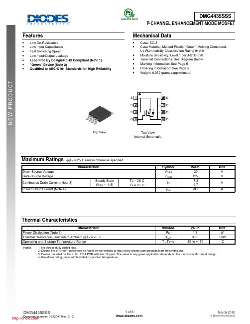
Features• Low On-Resistance • Low Input Capacitance • Fast Switching Speed • Low Input/Output Leakage • Lead Free By Design/RoHS Compliant (Note 1) • "Green" Device (Note 2) • Qualified to AEC-Q101 Standards for High ReliabilityMechanical Data• Case: SO-8 • Case Material: Molded Plastic, “Green” Molding Compound.UL Flammability Classification Rating 94V-0 • Moisture Sensitivity: Level 1 per J-STD-020 • Terminal Connections: See Diagram Below • Marking Information: See Page 5 • Ordering Information: See Page 5 • Weight: 0.072 grams (approximate)Maximum Ratings @T A = 25°C unless otherwise specifiedCharacteristicSymbol Value UnitDrain-Source Voltage V DSS -30 V Gate-Source VoltageV GSS±25 V Continuous Drain Current (Note 3) Steady State (V GS = -4.5)T A = 25°C T A = 85°CI D -7.3-4.7APulsed Drain Current (Note 4) I DM-80 AThermal CharacteristicsCharacteristic Symbol Value UnitPower Dissipation (Note 3) P D1.3 W Thermal Resistance, Junction to Ambient @T A = 25°C R θJA96.5 °C/W Operating and Storage Temperature Range T J , T STG-55 to +150 °C Notes: 1. No purposefully added lead.2. Diodes Inc.'s "Green" policy can be found on our website at /products/lead_free/index.php.3. Device mounted on 1in. x 1in. FR-4 PCB with 2oz. Copper. The value in any given application depends on the user’s specific board design.4. Repetitive rating, pulse width limited by junction temperature.Top ViewTop ViewInternal SchematicS D D GD DS SElectrical Characteristics @T A = 25°C unless otherwise specifiedCharacteristicSymbol Min Typ Max Unit Test ConditionOFF CHARACTERISTICS (Note 5) Drain-Source Breakdown VoltageBV DSS -30 - - V V GS = 0V, I D = -1mA Zero Gate Voltage Drain Current T J = 25°C I DSS - - -1.0 μA V DS = -30V, V GS= 0V Gate-Source LeakageI GSS - - ±100 nA V GS = ±25V, V DS = 0V ON CHARACTERISTICS (Note 5) Gate Threshold VoltageV GS(th) -1.0 -1.7 -2.5 V V DS = V GS , I D = -250μAStatic Drain-Source On-Resistance R DS (ON) - 13 16 m Ω V GS = -20V, I D= -11A15 20 V GS = -10V, I D = -10A21 29 V GS = -5V, I D = -5AForward Transfer Admittance |Y fs | - 22 - S V DS = -5V, I D = -10A Diode Forward VoltageV SD - -0.74 -1.0 V V GS = 0V, I S = -1ADYNAMIC CHARACTERISTICS (Note 6) Input Capacitance C iss - 1614 - pFV DS = -15V, V GS = 0V,f = 1.0MHzOutput CapacitanceC oss - 226 - pFReverse Transfer Capacitance C rss - 214 - pF Gate ResistanceR g - 6.8 - Ω V DS = 0V, V GS = 0V, f = 1MHz Total Gate Charge at 10V Q g - 35.4 - nC V GS = -10V, V DS = -15V, I D = -10A Total Gate Charge at 5V Q g - 18.9 - nCV GS = -5V, V DS = -15V,I D = -10AGate-Source Charge Q gs - 4.6 - nCGate-Drain Charge Q gd - 5.7 - nC Turn-On Delay Time t D(on) - 8.6 - ns V DS = -15V, V GS = -10V, R L = 1.5Ω, R GEN = 3Ω, Turn-On Rise Time t r - 12.7 - ns Turn-Off Delay Time t D(off) - 44.9 - ns Turn-Off Fall Timet f- 22.8 - nsNotes: 5. Short duration pulse test used to minimize self-heating effect.6. Guaranteed by design. Not subject to production testing.Fig. 1 Typical Output Characteristic-V , DRAIN-SOURCE VOLTAGE (V)DS -I , D R A I N C U R R E N T (A )D Fig. 2 Typical Transfer Characteristic-V , GATE-SOURCE VOLTAGE (V)GS -I , D R A I N C U R R E N T (A )DFig. 3 Typical On-Resistance vs. Drain Current and Gate Voltage-I , DRAIN-SOURCE CURRENT (A)D R , D R A I N -S O U R C E O N -R E S I S T A N C E ()D S (O N )Ω00.010.020.030.040.050.06-I , DRAIN CURRENT (A)D Fig. 4 Typical On-Resistance vs. Drain Current and TemperatureR , D R A I N -S O U R C E O N -R E S I S T A N C E ()D S (O N )ΩFig. 5 On-Resistance Variation with Temperature T , AMBIENT TEMPERATURE (°C)A R , D R A I N -S O U R C E O N -R E S I S T A N C E (N O R M A L I Z E D )D S O NR , D R A I N -S O U R C E O N -R E S I S T A N C E (N O R M A L I Z E D )D S O N Fig. 6 On-Resistance Variation with T emperatureT , AMBIENT TEMPERATURE (°C)AFig. 7 Gate Threshold Variation vs. Ambient T emperatureT , AMBIENT TEMPERATURE (°C)A -V , G A T E T H R E S H O L D V O L T A G E (V )G S(T H )Fig. 8 Diode Forward Voltage vs. Current-V , SOURCE-DRAIN VOLTAGE (V)SD -I , S O U R C E C U R R E N T (A )S101001,00010,000Fig. 9 Typical Total Capacitance-V , DRAIN-SOURCE VOLTAGE (V)DSFig. 10 Typical Leakage Current vs. Drain-Source Voltage-V , DRAIN-SOURCE VOLTAGE (V)DS -I , L E A K AG E C U R R E N T (n A )D S S Q , TOTAL GATE CHARGE (nC)g V , G A T E -T H R E S H O L D V O L T A G E (V )G S (T H )Fig. 11 Gate Threshold Voltage vs. Total Gate ChargeFig. 12 Transient Thermal Responset , PULSE DURATION TIME (s)1r (t ), T R A N S I E N T T H E R M A L R E S I S T A N C EOrdering Information (Note 7)Part Number Case PackagingDMG4435SSS-13SO-8 2500 / Tape & ReelNotes:7. For packaging details, go to our website at /datasheets/ap02007.pdf.Marking InformationPackage Outline DimensionsSuggested Pad LayoutSO-8Dim Min Max A - 1.75 A1 0.10 0.20 A2 1.30 1.50 A3 0.15 0.25 b 0.3 0.5 D 4.85 4.95 E 5.90 6.10 E1 3.85 3.95 e 1.27 Typ h - 0.35 L 0.62 0.82θ0° 8° All Dimensions in mmDimensionsValue (in mm)X 0.60 Y 1.55 C1 5.4 C21.27G4435SSLogo Part no.Xth week: 01~53Gauge Plane Seating PlaneDetail ‘A’XC2YIMPORTANT NOTICEDIODES INCORPORATED MAKES NO WARRANTY OF ANY KIND, EXPRESS OR IMPLIED, WITH REGARDS TO THIS DOCUMENT, INCLUDING, BUT NOT LIMITED TO, THE IMPLIED WARRANTIES OF MERCHANTABILITY AND FITNESS FOR A PARTICULAR PURPOSE (AND THEIR EQUIVALENTS UNDER THE LAWS OF ANY JURISDICTION).Diodes Incorporated and its subsidiaries reserve the right to make modifications, enhancements, improvements, corrections or other changes without further notice to this document and any product described herein. Diodes Incorporated does not assume any liability arising out of the application or use of this document or any product described herein; neither does Diodes Incorporated convey any license under its patent or trademark rights, nor the rights of others. Any Customer or user of this document or products described herein in such applications shall assume all risks of such use and will agree to hold Diodes Incorporated and all the companies whose products are represented on Diodes Incorporated website, harmless against all damages.Diodes Incorporated does not warrant or accept any liability whatsoever in respect of any products purchased through unauthorized sales channel. Should Customers purchase or use Diodes Incorporated products for any unintended or unauthorized application, Customers shall indemnify and hold Diodes Incorporated and its representatives harmless against all claims, damages, expenses, and attorney fees arising out of, directly or indirectly, any claim of personal injury or death associated with such unintended or unauthorized application.Products described herein may be covered by one or more United States, international or foreign patents pending. Product names and markings noted herein may also be covered by one or more United States, international or foreign trademarks.LIFE SUPPORTDiodes Incorporated products are specifically not authorized for use as critical components in life support devices or systems without the express written approval of the Chief Executive Officer of Diodes Incorporated. As used herein:A. Life support devices or systems are devices or systems which:1. are intended to implant into the body, or2. support or sustain life and whose failure to perform when properly used in accordance with instructions for use provided in thelabeling can be reasonably expected to result in significant injury to the user.B. A critical component is any component in a life support device or system whose failure to perform can be reasonably expected to cause the failure of the life support device or to affect its safety or effectiveness.Customers represent that they have all necessary expertise in the safety and regulatory ramifications of their life support devices or systems, and acknowledge and agree that they are solely responsible for all legal, regulatory and safety-related requirements concerning their products and any use of Diodes Incorporated products in such safety-critical, life support devices or systems, notwithstanding any devices- or systems-related information or support that may be provided by Diodes Incorporated. Further, Customers must fully indemnify Diodes Incorporated and its representatives against any damages arising out of the use of Diodes Incorporated products in such safety-critical, life support devices or systems.Copyright © 2010, Diodes Incorporated分销商库存信息: DIODESDMG4435SSS-13。
BTS443P中文资料
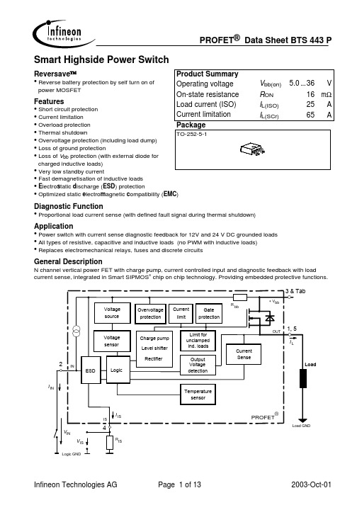
Diagnostic Function Application
• Proportional load current sense (with defined fault signal during thermal shutdown) • Power switch with current sense diagnostic feedback for 12V and 24 V DC grounded loads • All types of resistive, capacitive and inductive loads (no PWM with inductive loads) • Replaces electromechanical relays, fuses and discrete circuits
• Short circuit protection • Current limitation • Overload protection • Thermal shutdown TO-252-5-1 • Overvoltage protection (including load dump) • Loss of ground protection • Loss of Vbb protection (with external diode for charged inductive loads) • Very low standby current • Fast demagnetisation of inductive loads • Electrostatic discharge (ESD) protection • Optimized static electromagnetic compatibility (EMC)
PE塑料常用牌物性表

缠绕膜制造用的牌号(掺入30%)强度高于LDPE不含爽滑和开口掺2045G 和5100G增加强度掺AFFINITY-OG增加韧性LLDPE缠绕膜LLDPE缠绕膜LLDPE缠绕LLDPE 膜缠绕LLDPE 膜缠绕LLDPE膜缠绕LLDPE 膜缠绕LLDPE 膜缠绕LLDPE 膜缠绕膜LLDPE (6c)薄膜级LLDPE薄膜级LLDPE缠绕膜LLDPE (6c)缠绕膜LLDPE (6c)缠绕膜LLDPE( 8C线性)茂金属茂金属茂金属茂金属茂金属茂金属茂金属茂金属缠绕膜茂金属缠绕膜茂金属缠绕膜茂金属缠绕膜茂金属(6c)缠绕膜茂金属缠绕茂金属膜茂金属缠绕茂金属膜茂金属茂金属茂金属茂金属茂金属茂金属茂金属超低密度聚乙烯超低密度聚乙烯超低密度聚乙烯性体PE弹性体PE弹性体PE弹性体PP弹性体弹性体弹性体薄膜级LLDPE 薄膜级LLDPE薄膜级LLDPE 薄膜级LLDPE 薄膜级LLDPE 薄膜级LLDPE薄膜级LLDPE薄膜级LLDPE 薄膜LLDPE级薄膜LLDPE 级薄膜LLDPE 级薄膜LLDPE 级薄膜级LLDPE薄膜级LLDPE薄膜级LLDPE 薄膜级LLDPE薄膜级LLDPE 薄膜级LLDPE薄膜级LLDPE薄膜级LLDPE 薄膜级LLDPE薄膜级LLDPE薄膜级LLDPE 缠绕膜LLDPE缠绕膜LLDPE缠绕膜LLDPE缠绕膜LLDPE薄膜级LLDPE薄膜级LLDPE薄膜级LLDPE 薄膜级LLDPE 薄膜级LLDPE薄膜级LLDPE薄膜级LLDPE薄膜级LLDPE薄膜级LLDPE薄膜级LLDPE薄膜级LLDPE 薄膜级LLDPE薄膜级LLDPE薄膜级LLDPE 薄膜级LLDPE薄膜级LLDPE薄膜级LLDPE薄膜级LLDPE薄膜级LLDPE 薄膜级LLDPE薄膜级LLDPE 薄膜级LLDPE 薄膜级LLDPE薄膜级LLDPE薄膜级LLDPE薄膜级LLDPE薄膜级LLDPE薄膜级LLDPE1820S1印尼薄膜级LLDPE201XV福建联合薄膜级LLDPE7087科威特EQUATE1薄膜LLDPE新加坡级注塑级LLDPE 注塑级LLDPE注塑级LLDPE注塑级LLDPE注塑级LLDPE 注塑级LLDPE注塑级LLDPE注塑级LLDPE注塑级LLDPE注塑级LLDPE高压花料挤出涂覆级LDPE注塑级LDPELDPE 注塑级LDPELDPE 注塑级LDPELDPELDPELDPE高压涂覆挤出LDPE级涂覆LDPE 级涂覆LDPE 级涂覆LDPE 级注塑LDPE 级挤出LDPE 级挤出LDPE 级挤出LDPE 级LDPE高压薄膜LDPELDPELDPE高压重包装注塑LDPE级LDPELDPELDPE 薄膜级LDPE 薄膜级LDPE薄膜级LDPE薄膜级LDPE 薄膜LDPE级薄膜LDPE 级薄膜LDPE 级薄膜LDPE 级薄膜LDPE 级薄膜LDPE级薄膜LDPE 级薄膜LDPE 级薄膜LDPE 级薄膜LDPE 级薄膜LDPE 级薄膜LDPE 级薄膜LDPE 级薄膜LDPE级薄膜LDPE 级薄膜LDPE 级薄膜LDPE 级薄膜LDPE 级薄膜LDPE 级薄膜LDPE 级薄膜级LDPE薄膜级LDPE薄膜级LDPE 薄膜级LDPE薄膜级LDPE薄膜级LDPE 薄膜级LDPE薄膜级LDPE薄膜级LDPE薄膜级LDPE薄膜级LDPE薄膜级LDPE 薄膜级LDPE薄膜级LDPE薄膜级LDPE 薄膜LDPE级薄膜LDPE 级注塑LDPE 级Array注塑LDPE 级注塑LDPE级注塑LDPE 级注塑LDPE 级注塑LDPE 级注塑LDPE 级注塑LDPE 级注塑LDPE 级涂覆级LDPE 涂覆级LDPE涂覆级LDPE涂覆级LDPE 涂覆级LDPE涂覆级LDPE涂覆级LDPE 涂覆级LDPE涂覆级LDPE7008美国陶氏薄膜级HDPE薄膜级HDPE薄膜级HDPE薄膜级HDPE薄膜级HDPE薄膜级HDPE薄膜级HDPE 薄膜级HDPE薄膜级HDPE薄膜级HDPE薄膜级HDPE。
派克核电门户网站产品说明书
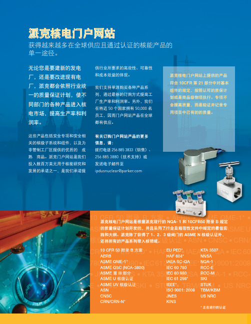
10 CFR 50 • AERB • ASME QME-1* • ASME QSC (NCA-3800) • ASME 第 III 部分 • ASME U核级认证核级认证 • ASN • CNSC CRN-N* HAF 604 • IAEA SC-QA 780 298* • IEEE* • ISO 9001: •E 派克核电门户网站无论您是要建新的发电厂,还是要改进现有电厂,派克都会依照行业统一的质量保证计划,使不同部门的各种产品进入核电市场,提高生产率和利润率。
这些产品包括安全专项和安全相关的核级子系统和组件,以及为非管制工厂区提供的优质的“成熟”商品。
派克门户网站是我们投入数百万美元用于核能研究和发展的承诺之一,是我们承诺提获得越来越多在全球供应且通过认证的核能产品的单一途径。
供行业所要求的高效性、可靠性和成本效益的体现。
我们支持单源购买各种产品系列,通过最新的订购方式提高工厂生产率和利润率。
另外,我们在将近 50 个国家拥有 50,000 名员工,因而门户网站产品在全球都有供应。
有关订购门户网站产品的更多信息,请:拨打电话 256 885 3833(销售)、256 885 3880(技术支持)或 发送电子邮件至 ipdusnuclear@parker .com派克核电门户网站是根据派克现行的 NQA- 1 和 10CFR50 附录 B 规定的质量保证计划开发的,并且采用了行业及规范性文件中规定的最佳实3 级阀门的 ASME N 核级认证外,派克核电门户网站上提供的产品符合 10CFR 第 21 部分中对基本组件的规定,按照认可的质保计划或是商品级物项执行。
专项不会提高质量,而是验证并记录专用项目中已有的的质量。
EU PED*HAF 604*IAEA SC-QA KTA 3507NNSANQA-1Parker Hannifin Ltd.Tachbrook Park DriveTachbrook Park,Warwick, CV34 6TU英国电话:+44 (0) 1926 317 878传真:+44 (0) 1926 317 855********************欧洲、中东和非洲AE – 阿联酋,迪拜电话:+971 4 8127100********************AT – 奥地利,维也纳新城电话:+43 (0)2622 23501-0*************************AT – 东欧,维也纳新城电话:+43 (0)2622 23501 900****************************AZ – 阿塞拜疆,巴库电话:+994 50 2233 458****************************BE/LU – 比利时,尼韦尔电话:+32 (0)67 280 900*************************BY – 白俄罗斯,明斯克电话:+375 17 209 9399*************************CH – 瑞士,埃托瓦电话:+41 (0)21 821 87 00*****************************CZ – 捷克共和国,Klecany电话:+420 284 083 111*******************************DE – 德国,卡尔斯特电话:+49 (0)2131 4016 0*************************DK – 丹麦,巴勒鲁普电话:+45 43 56 04 00*************************ES – 西班牙,马德里电话:+34 902 330 001***********************FI – 芬兰,万塔河电话:+358 (0)20 753 2500parker. ****************FR – 法国,Contamine s/Arve电话:+33 (0)4 50 25 80 25************************GR – 希腊,雅典电话:+30 210 933 6450************************HU – 匈牙利,布达佩斯电话:+36 23 885 470*************************IE – 爱尔兰,都柏林电话:+353 (0)1 466 6370*************************IT – 意大利,Corsico (MI)电话:+39 02 45 19 21***********************KZ – 哈萨克斯坦,阿拉木图电话:+7 7273 561 000****************************NL – 荷兰,奥尔登扎尔电话:+31 (0)541 585 000********************NO – 挪威,阿斯克尔电话:+47 66 75 34 00************************PL – 波兰,华沙电话:+48 (0)22 573 24 00************************PT – 葡萄牙,莱萨·达·帕尔梅拉电话:351 22 999 7360**************************RO – 罗马尼亚,布加勒斯特电话:+40 21 252 1382*************************RU – 俄罗斯,莫斯科电话:+7 495 645-2156************************SE – 瑞典,Spånga电话:+46 (0)8 59 79 50 00************************SK – 斯洛伐克,班斯卡·比斯特里察电话:+421 484 162 252**************************SL – 斯洛文尼亚,新梅斯托电话:+386 7 337 6650**************************TR – 土耳其,伊斯坦布尔电话:+90 216 4997081************************UA – 乌克兰,基辅电话:+380 44 494 2731*************************UK – 英国,沃里克电话:+44 (0)1926 317 878********************ZA – 南非,坎普顿公园电话:+27 (0)11 961 0700*****************************北美地区CA – 加拿大,安大略省米尔顿电话:+1 905 693 3000US – 美国,克利夫兰电话:+1 216 896 3000亚太地区AU – 澳大利亚,城堡山电话:+61 (0)2-9634 7777CN – 中国,上海电话:+86 21 2899 5000HK – 香港电话:+852 2428 8008IN – 印度,孟买电话:+91 22 6513 7081-85JP – 日本,东京电话:+81 (0)3 6408 3901KR – 韩国,首尔电话:+82 2 559 0400MY – 马来西亚,莎阿南电话:+60 3 7849 0800NZ – 新西兰,惠灵顿电话:+64 9 574 1744SG – 新加坡电话:+65 6887 6300TH – 泰国,曼谷电话:+662 186 7000-99TW – 台湾,台北电话:+886 2 2298 8987南美AR – 阿根廷,布宜诺斯艾利斯电话:+54 3327 44 4129BR – 巴西,圣若泽杜斯坎普电话:+55 800 727 5374CL – 智利,圣地亚哥电话:+56 2 623 1216MX – 墨西哥,阿波达卡电话:+52 81 8156 6000核电门户网站手册 M&K 12/10 1M派克授权的本地经销商© 2010 派克汉尼汾公司派克全球办事处联系信息欧洲产品信息中心免费电话:00 800 27 27 5374(AT, BE, CH, CZ, DE, DK, EE, ES, FI, FR, IE,IL, IS, IT, LU, MT, NL, NO, PL, PT, RU, SE,SK, UK, ZA)– 一点的方式。
ISO4433-3译文
国际标准ISO4433-3第一版1997-12-15热塑性塑料管材——耐液体化学物质——分类第三部分:硬聚氯乙烯(PVC-U),高抗冲聚氯乙烯(PVC-HI)和氯化聚氯乙烯(PVC-C)管材由佑利控股集团有限公司负责翻译参考编码ISO 4433-3:1997(E)ISO 4433-3:1997(E)前言ISO(国际标准化组织)是各国标准的国际化组织。
国际标准的准备起草工作由ISO技术委员会完成。
技术委员会为其成员国提出主题,委员会中感兴趣的成员都有权发表看法,阐述观点。
国际组织、政府部门和非政府部门与ISO 协作,也参加工作。
ISO与国际电工技术委员会IEC紧密协作,处理所有有关电工技术的标准。
由技术委员会采用的国际标准草案提交各成员国投票,至少占75%成员赞成,该草案才能正式作为国际标准出版。
ISO 4433-3是由技术委员会ISO/TC 138“输送液体用的塑料管材、管件和阀门”和分技术委员会SC 3“工业用的塑料管材和管件”指定制定。
ISO 4433本部分连同其他部分(见下面)撤消和代替ISO 4433:1984(技术内容已修订)。
在总标题——热塑性塑料管材——耐液体化学物质——的分类——下,ISO 4433包括以下几部分:——第一部分:浸泡试验方法——第二部分:聚烯烃管材——第三部分:硬聚氯乙烯(PVC-U),高抗冲聚氯乙烯(PVC-HI)和氯化聚氯乙烯(PVC-C)管材。
——第四部分:聚偏二氟乙烯(PVDF)管材。
ISO 4433本部分的附录A仅供参考。
ⅡISO 4433-3:1997(E)引言:ISO 4433本部分给出了PVC-U,PVC-HI和PVC-C管材耐化学浸蚀性的初步分类。
这种方法是基于浸泡试样的质量变化和拉伸性质的改变而确立的,这些试样采自于PVC管材的管壁,放置于将要输送的无压液体中。
如果管材将要在有应力存在下使用,例如在压力下输送液体,这种方法仅适用于在被测液体和管材不互溶的情况下;“耐浸蚀”或“有限的耐浸蚀”结果需要通过ISO 8584-1[1]和ISO/TR 8584-2[2](见附录A)提供的进一步试验来进一步证实。
国外PE100管材料牌号
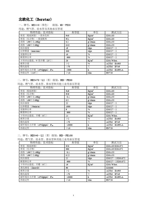
北欧化工〔Borstar)一、牌号:ME3440〔黑色〕级别:MD-PE80二、牌号:HE3470-LS〔黑〕级别:HD-PE80用途:燃气管、给水管、排水管和共他工业用承压管道三、牌号:HD340-LS〔黑〕级别:HD-PE100巴塞尔〔basell 赫思特〕一、牌号:GM5010T3〔黑色〕级别:HD-PE80二、牌号:GM5010T3〔本色〕级别:HD-PE80用途:内衬管、修补管、排污管、波纹管、工业用管。
三、牌号:CRP100〔黑〕级别:HD-PE100四、牌号:CRP100〔黄〕级别HE-PE100五、牌号:CRP100(蓝) 级别HD-PE100用途:给水管、修补管。
六、牌号:MPE80(黑色) 级别MD-PE80用途:燃气管、给水管、灌溉管等承压管道及管件。
七、牌号:MPE80(黄) 级别MD-PE80八、牌号:MPE80(蓝) 级别MD-PE80BP 苏威(Solvay)一、牌号:ELTEXTUB131 N2021(黑) 级别HD-PE80 用途:燃气管、给水管及下水管。
二、牌号:ELTEXTUB131 N2021(黑) 级别HD-PE80三、牌号:ELTEX TUB171(黑) 级别HD-PE80四、牌号:ELTEX TUB172 (黄) 级别HD-PE80六、牌号:ELTEX TUB121(黑) 级别HD-PE100七、牌号:ELTEX TUB124 (蓝) 级别HD-PE100九、牌号:ELTEX TUB125 N2025(橙) 级别HD-PE100Finathene 3802 B中高密度聚乙烯产品描述Finathene 3802 B 是一种以碳6已烯作为共聚单体的乙烯共聚物,采用连续低压淤浆聚合工艺制得。
Finathene 3802 B是一种中密度的聚乙烯黑色料,特别是开发用于饮用水及燃气的输送分配。
Finathene 3802 B属于PE-80,MRS-8指的是在按ISO/TR 9080 SEM法处推至50年使用寿命后,其抗内应力性能大于8Mpa.。
三元乙丙橡胶牌号
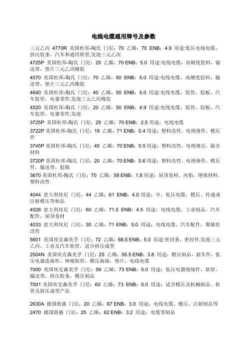
电线电缆通用牌号及参数三元乙丙4770R 美国杜邦-陶氏门尼:70 乙烯:70 ENB:4.9 用途:低压电线电缆,挤出胶条,汽车和通用软管,发泡三元乙丙4725P 美国杜邦-陶氏门尼:25 乙烯:70 ENB:5.0 用途:电线电缆,高硬度胶料,输送带,垫片三元乙丙橡胶4570 美国杜邦-陶氏门尼:70 乙烯:50 ENB:5.0 用途:电线电缆,高硬度胶料,输送带,垫片三元乙丙橡胶4640 美国杜邦-陶氏门尼:40 乙烯:55 ENB:5.0 用途:电线电缆,胶管,胶板,汽车胶管,电器零件,发泡三元乙丙橡胶4520 美国杜邦-陶氏门尼:20 乙烯:50 ENB:4.9 用途:电线电缆,胶管,胶板,汽车胶管,电器零件,发泡3725P 美国杜邦-陶氏门尼:25 乙烯:70 ENB:2.5用途:电线电缆3722P美国杜邦-陶氏门尼:19 乙烯:71 ENB:0.4用途:塑料改性,电绝缘件,模压件3745P美国杜邦-陶氏门尼:45 乙烯:70 ENB:0.5用途:塑料改性,电绝缘层,隔音材料3720P美国杜邦-陶氏门尼:20 乙烯:70 ENB:0.6用途:塑料改性,电绝缘件,模压件,输送带,胶辊3670美国杜邦-陶氏门尼:70 乙烯:58 ENB:1.8用途:屋顶卷材,内胎,绝缘材料,塑料改性4044 意大利埃尼门尼:44 乙烯:61 ENB:4.0用途:中、低压电缆,模压、传递或注射模压等制品4028 意大利埃尼门尼:60 乙烯:71.5 ENB:4.5 用途:电线电缆,工业制品,汽车配件,屋顶卷材4033 意大利埃尼门尼:30 乙烯:71 ENB:5.0 用途:电线电缆,汽车配件,聚烯烃改性5601 美国埃克森美孚门尼:72 乙烯:68.5 ENB:5.0 用途:密封条,密封件,发泡三元乙丙,工业及汽车软管,适合挤压成型2504N 美国埃克森美孚门尼:25 乙烯:55.5 ENB:3.8 用途:模压制品,刹车件,低压电器连接件,伸缩软管,模压海绵,垫片,电线电缆7000 美国埃克森美孚门尼:59 乙烯:73 ENB:5.0 用途:低压电器绝缘件,软管,输送带,挤出胶条,模压制品7001美国埃克森美孚门尼:60 乙烯:73 ENB:5.0 用途:适合模压及机械制品、软管及挤压成型产品2630A 德国朗盛门尼:20 乙烯:67 ENB:3.0 用途:电线电缆,模压、注射制品等2470 德国朗盛门尼:25 乙烯:62 ENB:3.2 用途:电缆等制品。
4435场效应管参数

4435场效应管参数场效应管(Field Effect Transistor,FET)是一种三端器件,由晶体管中的PN结演化而来。
它通过控制栅极与漏极之间的电场来控制电流流动,具有高输入电阻、低噪声、低功耗等优点,因此广泛应用于模拟电路和数字电路中。
以下是关于场效应管参数的详细介绍。
1.析取:场效应管由源极、漏极和栅极组成。
其中,源极是电流输入端,漏极是电流输出端,栅极用于控制电流流动。
栅极与源极之间的电场决定了漏极-源极通道的导电能力。
2.通道类型:场效应管根据通道类型可以分为N沟道(N-Channel)和P沟道(P-Channel)两种。
N沟道场效应管中,通道为N型半导体,漏极为N型,栅极为P型;P沟道场效应管中,通道为P型半导体,漏极为P型,栅极为N型。
3. 漏极-源极导通电阻(RDS(on)):RDS(on)是场效应管导通状态下的漏极-源极电阻。
它是一个关键的参数,决定了场效应管的功耗和工作温度。
RDS(on)越小,表示场效应管导通时的电阻越小,功耗也越小。
因此,低RDS(on)的场效应管适用于高功率应用,如电力电子设备。
4.最大漏极-源极电压(VDS)和最大栅极-源极电压(VGS):VDS和VGS是场效应管能够承受的最大电压。
在超过最大电压范围时,场效应管可能发生击穿或损坏。
因此,在设计电路时,应注意选择适当的场效应管,确保其能够承受设计电路中的最大电压。
5.漏极电流(ID)和栅极电流(IG):ID是从漏极流出的电流,是场效应管的输出电流。
IG是注入到栅极的电流,用于控制场效应管的导通与截止。
实际工作中,栅极电流通常很小,可以忽略。
而漏极电流与栅极电压的关系可以通过场效应管的转移特性曲线(ID-VGS曲线)来描述。
6.转移特性曲线:转移特性曲线是场效应管在不同栅极电压下的漏电流-栅极电压关系曲线。
通过转移特性曲线,可以了解场效应管的导通与截止电压范围以及漏电流与栅极电压之间的关系。
根据转移特性曲线,可以确定适合特定应用的场效应管。
AP4435GM中文资料

P-CHANNEL ENHANCEMENT MODE POWER MOSFET▼ Simple Drive Requirement BV DSS -30V ▼ Low On-resistanceR DS(ON)20m Ω▼ Fast Switching CharacteristicI D-9ADescriptionAbsolute Maximum RatingsSymbol Units VDS V V GSV I D @T A =25℃A I D @T A =70℃A I DMA P D @T A =25℃W W/℃T STG ℃T J℃Symbol Value Unit Rthj-aMaximum Thermal Resistance, Junction-ambient350℃/WData and specifications subject to change without notice 1200811216AP4435GMRating - 30+ 20-90.02ParameterDrain-Source Voltage Gate-Source Voltage Continuous Drain Current 3Linear Derating Factor Storage Temperature RangeContinuous Drain Current 3-7.3Pulsed Drain Current 1-50RoHS-compliant ProductThermal DataParameterTotal Power Dissipation 2.5-55 to 150Operating Junction Temperature Range-55 to 150Advanced Power MOSFETs from APEC provide the designer with the best combination of fast switching,ruggedized device design, low on-resistance and cost-effectiveness.The SO-8 package is widely preferred for all commercial-industrial surface mount applications and suited for low voltage applications such as DC/DC converters.S SS GDD DDSO-8Electrical Characteristics@T j =25oC(unless otherwise specified)Symbol ParameterTest ConditionsMin.Typ.Max.Units BV DSS Drain-Source Breakdown Voltage V GS =0V, I D =-250uA -30--V R DS(ON)Static Drain-Source On-Resistance 2V GS =-10V, I D =-7A --20m ΩV GS =-4.5V, I D =-5A--32m ΩV GS(th)Gate Threshold Voltage V DS =V GS , I D =-250uA -1--3V g fs Forward Transconductance V DS =-10V, I D =-7A -16-S I DSS Drain-Source Leakage Current V DS =-30V, V GS =0V ---1uA Drain-Source Leakage Current (T j =70o C)V DS =-24V, V GS =0V---25uA I GSS Gate-Source Leakage V GS =+20V --+100nA Q g Total Gate Charge 2I D =-7A -1829nC Q gs Gate-Source Charge V DS =-24V -3-nC Q gd Gate-Drain ("Miller") Charge V GS =-4.5V -10-nC t d(on)Turn-on Delay Time 2V DS =-15V -8-ns t r Rise TimeI D =-1A- 6.6-ns t d(off)Turn-off Delay Time R G =3.3Ω,V GS =-10V -44-ns t f Fall Time R D =15Ω-34-ns C iss Input Capacitance V GS =0V -11751690pF C oss Output CapacitanceV DS =-25V -195-pF C rssReverse Transfer Capacitancef=1.0MHz-190-pFSource-Drain DiodeSymbol ParameterTest ConditionsMin.Typ.Max.Units V SD Forward On Voltage 2I S =-2.1A, V GS =0V ---1.2V t rr Reverse Recovery Time2I S =-7A, V GS =0V,-28-ns Q rrReverse Recovery ChargedI/dt=100A/µs-18-nCNotes:1.Pulse width limited by Max. junction temperature.2.Pulse testTHIS PRODUCT IS SENSITIVE TO ELECTROSTATIC DISCHARGE, PLEASE HANDLE WITH CAUTION.USE OF THIS PRODUCT AS A CRITICAL COMPONENT IN LIFE SUPPORT OR OTHER SIMILAR SYSTEMS IS NOT AUTHORIZED.APEC DOES NOT ASSUME ANY LIABILITY ARISING OUT OF THE APPLICATION OR USE OF ANY PRODUCT OR CIRCUIT DESCRIBED HEREIN; NEITHER DOES IT CONVEY ANY LICENSE UNDER ITS PATENT RIGHTS, NOR THE RIGHTS OF OTHERS.APEC RESERVES THE RIGHT TO MAKE CHANGES WITHOUT FURTHER NOTICE TO ANY PRODUCTS HEREIN TO IMPROVE RELIABILITY, FUNCTION OR DESIGN.2AP4435GM3.Surface mounted on 1 in 2 copper pad of FR4 board, t <10sec ; 125 ℃/W when mounted on Min. copper pad.AP4435GMFig 1. Typical Output Characteristics Fig 2. Typical Output CharacteristicsFig 3. On-Resistance v.s. Gate VoltageFig 4. Normalized On-Resistancev.s. Junction TemperatureFig 5. Forward Characteristic ofFig 6. Gate Threshold Voltage v.s. Reverse DiodeJunction TemperatureFig 7. Gate Charge CharacteristicsFig 9. Maximum Safe Operating Area Fig 10. Effective Transient Thermal ImpedanceFig 11. Transfer Characteristics Fig 12. Gate Charge CircuitAP4435GMG。
常见原材料性能指标-张群甲 青岛优派普环保科技股份有限公司
PN049-030-122 天津大乙烯
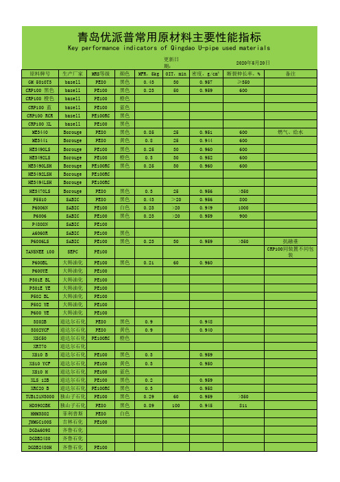
பைடு நூலகம்
青岛优派普常用原材料主要性能指标
Key performance indicators of Qingdao U-pipe used materials
更新日期: 原料牌号 GM 5010T3 CRP100 黑色 CRP100 橙色 CRP100 蓝 CRP100 RCR CRP100 XL ME3440 ME3441 HE3490LS HE3492LS HE3490LSH HE3492LSH HE3494LSH HE3470LS P5510 P6006N P6006 P4808N A6060R P6006LS TANSNEE 100 P600BL P600YE P301E BL P301E YE P502 BL P502 YE P600 YE 3802B 3802YCF XSC50 XRT70 XS10 B XS10 YCF XS10 H XLS 12B XRC20 B TUB121N3000 HD3902BK HHM3802 JHMGC100S DGDA6098 DGDB2480 DGDB2480H DGDB2480HBK 生产厂家 basell basell basell basell basell basell Borouge Borouge Borouge Borouge Borouge Borouge Borouge Borouge SABIC SABIC SABIC SABIC SABIC SABIC SEPC 大韩油化 大韩油化 大韩油化 大韩油化 大韩油化 大韩油化 大韩油化 道达尔石化 道达尔石化 道达尔石化 道达尔石化 道达尔石化 道达尔石化 道达尔石化 道达尔石化 道达尔石化 独山子石化 独山子石化 菲利普斯 吉林石化 齐鲁石化 齐鲁石化 齐鲁石化 齐鲁石化 PE100 PE100 黑色 0.32 70 0.952 840 PE100 PE100 PE100 PE100 PE100RC PE100 PE80 PE80 PE100 黑色 黄色 蓝色 黑色 黑色 黑色 黑色 白色 0.2 0.3 0.29 0.89 60 100 0.959 0.958 0.959 0.945 >350 811 0.3 0.3 0.959 0.950 MRS等级 PE80 PE100 PE100 PE100 PE100RC PE100 PE80 PE80 PE100 PE100 PE100RC PE100RC PE100RC PE80 PE80 PE100 PE100 PE100 PE100 PE100 PE100 PE100 PE100 PE100 PE100 PE100 PE100 PE100 PE80 PE80 PE100RC 黑色 黄色 橙色 0.9 0.9 0.948 0.940 黑色 0.21 60 0.960 黑色 黑色 0.23 30 0.959 >350 抗融垂 CRP100同装置不同包装 黑色 黑色 白色 黑色 0.3 0.43 0.23 0.23 25 >20 >20 >20 0.956 0.956 0.949 0.959 >350 800 1000 900 颜色 黑色 黑色 橙色 蓝色 黑色 黑色 黑色 黄色 黑色 橙色 黑色 0.85 0.8 0.25 0.3 0.25 25 25 30 30 30 0.951 0.944 0.960 0.952 0.960 600 600 600 600 600 燃气、给水 MFR,5kg 0.43 0.23 OIT,min 30 50 密度,g/cm³ 0.957 0.959 2015年3月20日 断裂伸长率,% ≥350 600 备注
聚乙烯常见牌号及用途
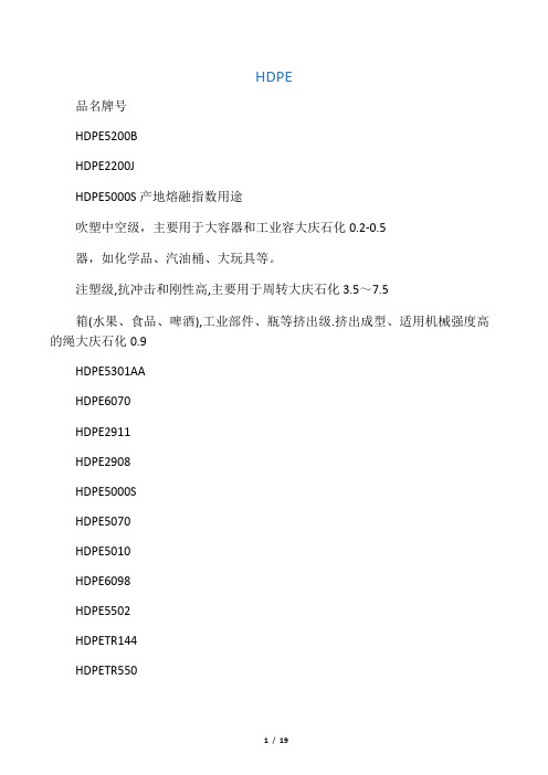
HDPE品名牌号HDPE5200BHDPE2200JHDPE5000S产地熔融指数用途吹塑中空级,主要用于大容器和工业容大庆石化0.2-0.5器,如化学品、汽油桶、大玩具等。
注塑级,抗冲击和刚性高,主要用于周转大庆石化3.5~7.5箱(水果、食品、啤酒),工业部件、瓶等挤出级.挤出成型、适用机械强度高的绳大庆石化0.9HDPE5301AAHDPE6070HDPE2911HDPE2908HDPE5000SHDPE5070HDPE5010HDPE6098HDPE5502HDPETR144HDPETR550HDPETR480 HDPE50100 HDPE5502AA HDPE5301AA HDPEMH602 HDPECH2802 HDPE5200B HDPE5000S HDPE7000F HDPE5306J独山子独山子石化抚顺乙烯抚顺乙烯兰州石化盘锦乙烯盘锦乙烯齐鲁石化上海金菲上海金菲上海金菲上海金菲上海金菲上海赛科上海赛科上海石化上海石化燕山石化燕山扬子石化扬子石化索和阀用单丝。
0.08挤出.可用于绳索和网用单丝,而且可用于中空制品、管材等。
6.5-9.0薄膜级,包装使用购物袋,薄壁袋等20注塑级8注塑级.家俱、一般容器、薄壁容器、周转箱、托盘、体育设施、安全帽、鱼箱0.8-1.2注塑级.家俱、一般容器、薄壁容器、周转箱、托盘、体育设施、安全帽、鱼箱6.1-8.0挤出.可用于绳索和网用单丝,而且可用于中空制品、管材等。
0.6-1.0注塑级.鱼箱、板条箱、手提箱。
9.0~14.0拉丝级.生产单丝、扁丝、制鱼网、绳等。
0.25-0.45薄膜级,良好的耐热性和耐寒性。
生产购物袋、杂货袋、多层衬里膜、耐候膜等0.16-0.22产品袋、垃圾袋、多层复合袋、购物袋。
20.08~0.14燃烧气,上水管,工程管。
7.5-11.0200升桶、油箱、托板、大型部件、游艇。
0.2洗涤剂、化妆品瓶;工业化学品容器;电动机润滑油瓶。
Si4435BDY中文资料

3
DESCRIPTION
The attached spice model describes the typical electrical characteristics of the p-channel vertical DMOS. The subcircuit model is extracted and optimized over the −55 to 125°C temperature ranges under the pulsed 0-V to 10-V gate drive. The saturated output impedance is best fit at the gate bias near the threshold voltage. A novel gate-to-drain feedback capacitance network is used to model the gate charge characteristics while avoiding convergence difficulties of the switched Cgd model. All model parameter values are optimized to provide a best fit to the measured electrical data and are not intended as an exact physical interpretation of the device.
Notes a. Pulse test; pulse width ≤ 300 µs, duty cycle ≤ 2%. b. Guaranteed by design, not subject to production testing.
德标1.4435化学成分标准

德标1.4435化学成分标准1. 引言德标1.4435是一种常见的不锈钢材料,具有优良的耐腐蚀性能和机械性能,被广泛应用于化工、制药、食品加工等领域。
为了确保1.4435材料的质量和性能,德国国家标准化组织制定了1.4435化学成分标准,对其成分和性能进行了严格规定。
2. 化学成分标准根据德国标准化组织的要求,1.4435材料的化学成分必须符合以下标准:- 碳含量(C):不超过0.05%- 硅含量(Si):不超过1.00%- 锰含量(Mn):不超过2.00%- 硫含量(S):不超过0.015%- 磷含量(P):不超过0.045%- 铬含量(Cr):16.5%-18.5%- 镍含量(Ni):10.0%-13.0%- 钼含量(Mo):2.0%-2.5%- 铜含量(Cu):不超过0.50%- 钛含量(Ti):不超过0.70%- 铌含量(Nb):0.10%-0.30%- 钙含量(Ca):不超过0.12%- 铁含量(Fe):余量3. 化学成分标准的意义化学成分是决定不锈钢材料性能的关键因素之一。
严格控制1.4435材料的化学成分,可以保证其具有良好的耐腐蚀性能、机械性能和加工性能。
碳含量的控制可以影响材料的强度和硬度,硅、锰、磷、硫等元素的含量则会影响材料的耐蚀性和加工性能。
而铬、镍、钼等元素的含量则是决定不锈钢材料耐腐蚀性能的关键因素。
4. 成分分析方法为了确保1.4435材料的化学成分符合标准要求,需要采用严格的成分分析方法进行检测。
常用的成分分析方法包括化学成分分析、光谱分析、金相分析、显微组织分析等。
通过这些分析方法,可以准确地测定1.4435材料中各种元素的含量,确保其符合标准要求。
5. 结论德标1.4435化学成分标准的制定,对保证1.4435材料的质量和性能起到了至关重要的作用。
通过严格控制材料的化学成分,可以确保其具有优良的耐腐蚀性能和机械性能,满足不同工程领域的需求。
对成分的准确分析也是保证材料质量的重要手段,为材料的生产和应用提供了可靠的保障。
乙烯基三氯硅烷牌号

乙烯基三氯硅烷牌号乙烯基三氯硅烷是一种常用的有机硅化合物,其牌号通常用于标识具体的化学成分和性能特点。
下面将介绍几种常见的乙烯基三氯硅烷牌号及其应用。
1. 牌号A-151A-151是一种乙烯基三氯硅烷,它具有良好的粘接性能和耐候性,常用于建筑密封、汽车玻璃密封和电子组件密封等领域。
其粘接剂能够在接触材料表面形成牢固的化学键,从而实现密封、固定和保护的效果。
此外,A-151还可用于制备聚硅氧烷树脂,该树脂具有优异的耐热性和电绝缘性能,常用于电子封装材料和高温密封材料等领域。
2. 牌号VTEOVTEO是一种乙烯基三氯硅烷,其特点是具有低粘度、低温固化和良好的粘接性能。
VTEO通常用于制备硅胶,硅胶具有优异的拉伸强度、耐候性和化学稳定性,广泛应用于建筑、电子、医疗和汽车行业等。
在建筑领域,VTEO可用于制备防水涂料、防水胶带和密封胶等,提供优异的防水、密封和耐候性能。
在电子领域,VTEO可用于制备导热硅胶,用于电子元件的散热和保护。
3. 牌号KBM-603KBM-603是一种乙烯基三氯硅烷,其主要用途是作为填料表面处理剂。
填料表面处理剂能够改善填料与基体之间的相容性,提高填料的分散性和加工性能。
KBM-603可用于处理多种填料,如二氧化硅、碳黑和陶瓷颗粒等。
通过使用KBM-603,填料与基体之间的界面相互作用得到增强,从而提高填料的增强效果和综合性能。
此外,KBM-603还能够提高填料与基体之间的化学键强度,从而提高复合材料的强度和耐久性。
4. 牌号VS171VS171是一种乙烯基三氯硅烷,其特点是具有高固体含量、低粘度和良好的粘接性能。
VS171常用于制备高性能的硅烷改性聚合物,该聚合物具有优异的粘接强度、耐化学性和耐候性,广泛应用于涂料、胶黏剂和密封剂等领域。
在涂料领域,VS171可用于制备硅烷改性丙烯酸酯乳液,提供涂层的附着力、耐候性和耐化学性。
在胶黏剂领域,VS171可用于制备硅烷改性聚氨酯胶黏剂,提供优异的粘接强度和耐化学性。
美标高压锅炉管常用牌号
美标高压锅炉管常用牌号美标高压锅炉管是应用于锅炉系统中耐高温高压的重要管道材料,具有优异的耐腐蚀、耐高温和耐压性能。
为了满足各种不同应用场景的需求,美标高压锅炉管有多种常用牌号。
本文将介绍这些常用牌号及其特点。
一、常用牌号1. ASTM A335 P11ASTM A335 P11是美标高压锅炉管的一种常用牌号,主要用于制造高压蒸汽管道。
它具有优异的耐腐蚀性能,能够在高温高压环境下长期稳定运行。
此外,ASTM A335 P11还具有良好的机械性能和焊接性能,易于加工和安装。
2. ASTM A335 P22ASTM A335 P22也是一种常用的美标高压锅炉管牌号,主要用于制造高温过热器管道。
与ASTM A335 P11相比,ASTM A335 P22具有更高的耐腐蚀性能和更高的耐温性能。
它能够在高温环境下长期稳定运行,并且具有较好的机械性能和焊接性能。
3. ASTM A106 BASTM A106 B是一种常用的美标无缝钢管牌号,也可用于制造高压锅炉管道。
它具有良好的耐腐蚀性能和机械性能,能够承受高温高压环境下的运行。
此外,ASTM A106 B还具有较好的可焊性和可加工性,易于安装和使用。
二、选用建议在选择美标高压锅炉管时,应根据具体的应用场景和需求进行选择。
对于需要承受高温高压的蒸汽管道,建议选用ASTM A335 P11或ASTM A335 P22;对于需要承受高温过热器管道,建议选用ASTM A335 P22;对于需要承受一般高压的管道,建议选用ASTM A106 B。
此外,在选择时还需考虑管道的尺寸、壁厚等因素,以确保管道的安全性和稳定性。
三、注意事项1. 在使用美标高压锅炉管时,应确保管道的安装和使用符合相关标准和规范的要求。
2. 在安装和使用过程中,应注意保护管道免受机械损伤和化学腐蚀。
3. 在使用过程中,应定期对管道进行检查和维护,以确保其安全性和稳定性。
4. 如果遇到管道损坏或故障,应及时进行维修或更换。
q355化学成分
q355化学成分
q355是一种高强度低合金结构钢,主要用于制造桥梁、船舶、车辆、机械等重要结构件。
其化学成分包括碳(C)、硅(Si)、锰(Mn)、磷(P)、硫(S)、铬(Cr)、镍(Ni)、铜(Cu)、钼(Mo)、钛(Ti)等元素。
其中,碳的含量为0.14%-0.22%,硅的含量为0.15%-0.50%,锰的含量为0.60%-1.65%,磷和硫的含量分别为不超过0.025%,铬的含量为不超过0.30%,镍的含量为不超过0.30%,铜的含量为不超过0.30%,钼的含量为不超过0.10%,钛的含量为不超过0.20%。
这些元素的含量控制得当,可以使q355钢具有优异的力学性能和耐腐蚀性能,从而保证其在重要结构件中的应用安全可靠。
- 1 -。
