左滑门
纳智捷电动滑门故障解析

第八步 取下隔音屏后饰板
11
第九步 取下隔音屏后舱上饰板(螺丝从前舱拆解)
12
第十步 拆隔音屏后舱喇叭(两个)
13
第十一步 拆隔音屏支架
14
第十二步 拆隔音屏支架线束
15
第十三步 拆隔音屏支架底座螺栓
16
第十四步 抬下隔音屏
17
电动滑门故障解析
1
故障现象
• 左侧滑门无自动滑开的功能
2
电动滑门工作原理
3
第一步 拆卸驾驶室左右座椅
4
第二步 拆解如图四个螺栓(共八个)
5
第三步 拆解B柱饰板
6
第四步 拆解B柱下饰板
7
第五步 拆解前舱隔音屏下ቤተ መጻሕፍቲ ባይዱ板
8
第六步 拆解前舱隔音屏上饰板
9
第七步 拆解后舱隔音屏下饰板螺栓(在前舱拆解八颗螺帽)
dooors2攻略
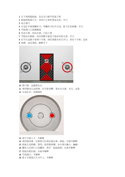
1 右下角钥匙捡起,怎么开门就不用说了吧2 捡起两块绿立方,对应门上的位置这么好,开门3 向左滑门4 右边打开找到螺丝刀,用螺丝刀打开左边,按下红色按键,开门5 手机照门上的图横放6 先向左滑,再向右滑,门向上滑7 手机向右倾斜,对应的数字就是下面对应的方块,开门8 打开右边箱子拿到十字架,绿灯到箭头时点开门,拿出十字架,走你9 如图,试出来的,解释不了10 滑门吧,总能滑出去11 来回移动左边的球,打开恐龙嘴,拿出灭火器,灭火,走你12 右边打开,如图颜色13 两个手指上下,不解释14 来回滚动球,后面的小红球会滚出来,捡起,后面不解释15 捡起左边的棍,使用,按顶部按键,由小到大输入,241316 螺丝刀去掉门上的螺丝,两手一起按按钮,后面不解释17 捡起扫把扫地,后面不解释18 手机倒立,不解释19 把十字架放白人马手上,不解释20 水池左边找到游泳眼镜,戴上,点水池,扫把扫墙,后面不解释21 两个手指向右滑门22 手指按出烟孔,颜色改成如图,解释不了23 很明显,不解释24 第2个道具插到右边,掰下,后面真不想解释,2874,上面分别是1234567825 让绿球落下,红球不能落下,自己想办法26 扫把把墙先打扫一下,熊猫当然在天朝,海龟?在南美洲左边的上面那个按钮27 右边拿到火柴,左边的往下滑,然后使用火柴和灭火器,然后就没有然后了28 点开调酒瓶,做死的摇手机29 如图,解释不了30 按蹦床,不解释了31 点右边酒桶,用螺丝刀打开,眼镜戴上,下去拿把刀,后面不解释了32 手机按图做圆周运动33 三个手指头一起按34 左边接出来,右边拉出来,加减法会的吧35 按大小换颜色,不解释36 第1个和第5个道具放秤上称一下,后面不解释了37 关灯,看颜色,输入对应颜色方块数量38 扫把卡住齿轮,两边接通就好了,难得截图了39 头朝下,是手机的头,左右慢慢的晃动手机,绿色的与白色的合并后就不解释了40 向右拉玻璃门,刀上。
汽车电动滑门设计研讨
汽车电动滑门设计研讨崔炳林;赵云聪【摘要】Automobile Power sliding doors (PSD) system is advanced sliding door system which integrated electronic intelligent control technology and sensor technology based on the sliding door system,and which is widely used in luxury commercial car, and which is more and more popular for consumers because of both the opening convenience of sliding side door and human-machine intelligent controlling.Refer to JAC M6 item,this article describes the technical components and theory of the automotive power sliding door subsystem, and achieves the innovative development of the power sliding door system.%汽车电动滑门(PSD)系统是在滑门系统的基础上,集成电子智能控制技术和传感器防夹技术的高级滑门系统,广泛应用于高档豪华商务车,兼具了滑门侧开启方便性和人机智能控制性,越来越受到消费者的青睐。
本文结合江淮M6项目,介绍了汽车电动滑门的各子系统构成和原理,实现了电动滑门系统的自主开发。
【期刊名称】《汽车实用技术》【年(卷),期】2014(000)008【总页数】3页(P19-21)【关键词】电动滑门(PSD);驱动系统;供电系统;驱动电机;霍尔传感器;控制单元【作者】崔炳林;赵云聪【作者单位】江淮汽车技术中心,安徽合肥 230601;江淮汽车技术中心,安徽合肥 230601【正文语种】中文【中图分类】U463CLC NO.:U463Document Code:AArticle ID:1671-7988(2014)08-19-03汽车电动滑门系统是在机械滑门系统的基础上,集成智能控制和执行技术的高级滑门系统,包括除车门本体系统、车门运动导向系统(铰链、导轨、限位组件)、机械门锁系统等机械滑门子系统外,还包括车门驱动系统、车门门锁系统、车门供电系统、安全防夹系统、车门控制单元等电动滑门子系统。
《极限脱出3》全密室解密图文流程攻略

《极限脱出3》全密室解密图⽂流程攻略 游戏介绍 《极限脱出3:零时困境》为备受玩家好评的“极限脱出”的最新作,将会延续该系列⼀贯的探索和压抑风格。
据官⽅消息,《极限脱出3:零时困境》的背景设定在《极限脱出999:9⼩时9⼈9扇门》的事件发⽣⼀年后。
新作中会看到前作中⼈物的回归和后续。
《极限脱出3:零时困境》中将会有10名⾓⾊登场,事件场景部分将会是实机3D建模来表现。
游戏的故事发⽣在2028年12⽉,也就是在《极限脱出:9⼩时9⼈9门》⼀年以后。
在《极限脱出:善⼈死亡》发⽣的时间中间,发⽣了《极限脱出:零时困境3》的事件。
界⾯操作 移动⿏标:选择; ⿏标左键:确认; 点击后退按钮:返回;%{p a g e-b r e a k|游戏介绍&界⾯操作|p a g e-b r e a k}% 第⼀章:掷硬币 剧情:(2028年12⽉31⽇)D c o m在D e v a d a沙漠的防空洞内,9名被困少年苏醒过来,他们⼿上都被带上了⼿铐,他们分别三⼈为⼀组被囚禁在三个禁闭室内。
⽽且囚室的铁门只能够从外⾯打开。
其中⼀名带着头套的⼩孩似乎在场其他⼈都不认识。
此时⼀个⾃称是零⼆世的⼈出现,他表⽰在在座9个⼈参加⼀场游戏,他会掷出⼀个硬币(他称之为关系到全⼈类的游戏),然后让⼩队领袖卡洛斯代表其余九个⼈猜藏在零⼆世脚下的硬币是哪个⾯?答对就能够拯救这⾥的所有⼈,答错就需要参加杀⼈游戏。
s t e p1.第⼀次猜就选择蓝⾊,是正确答案,那么就可以开启游戏当中最快达成的解决。
第⼆次正确答案是红⾊,要进⾏游戏,就得选择错误的答案。
剧情:(C Q D:E N D1)零⼆世表⽰会释放所有⼈,但需要所有⼈都睡去,在频临晕厥时,卡洛斯似乎意识到零⼆世是何许⼈也。
当众⼈醒来后,他们发现已经置⾝于防空洞的户外,可是他们的记忆都被消除,只有隐约记得⼀些东西。
s t e p2.重新选择掷硬币,就随意选择Q、C、D任意⼀队,然后在选择⽚段中重新选择掷硬币,选择错误那个就可以正式开启游戏。
滑动门原理
滑动门原理
滑动门是一种常见的门窗类型,其原理是通过滑轨和滑块的配合,使门扇可以在水平方向上滑动开合。
它的结构简单、使用方便,因此在现代建筑中得到了广泛的应用。
下面我们就来详细了解一下滑动门的原理。
首先,滑动门的主要结构包括门扇、滑轨、滑块和固定框。
门扇是由门框和玻璃等材料组成的移动部分,滑轨则是固定在地面上的导向轨道,滑块则是连接门扇和滑轨的零件,固定框则是门扇的支撑结构。
这些部件共同协作,使得滑动门可以顺利地开合。
在滑动门的使用过程中,滑块起着至关重要的作用。
它通过与滑轨的配合,使得门扇可以在水平方向上轻松地滑动。
而滑轨的设计也是十分关键的,它需要保证门扇的稳定性和平稳性,同时还要考虑到门扇的重量和使用寿命,因此滑轨的材料和制作工艺都需要经过精心设计和选择。
另外,滑动门的密封性也是需要重点考虑的问题。
为了保证室内外的隔音和隔热效果,滑动门需要在门扇和固定框之间设置密封条,以减少空气和声音的流失。
同时,为了增加门扇的稳定性,滑动门的固定框通常会采用钢铝材质,以确保门扇在使用过程中不会产生晃动和变形。
除此之外,滑动门的设计还需要考虑到人性化的因素。
比如,门把手的设计需要符合人体工程学,使得用户在开合门扇时感觉舒适,同时还需要考虑到门扇的防夹手设计,以确保用户在使用过程中不会受伤。
总的来说,滑动门的原理是通过滑轨和滑块的配合,使得门扇可以在水平方向上滑动开合。
在实际的设计和制作过程中,需要考虑到滑轨、滑块、固定框、密封性和人性化等多个方面的因素,以确保滑动门的稳定性、使用寿命和用户体验。
希望本文对滑动门的原理有所帮助,谢谢阅读!。
比亚迪M6电动滑动门原理与维修(可编辑)

比亚迪M6电动滑动门原理与维修(可编辑)比亚迪M6电动滑动门原理与维修M6电动滑动门技术??品质??责任1 滑门简介2 滑门结构及原理3 电动滑门诊断系统4 滑门拆装5 滑门保养6 滑门常见故障检修技术??品质??责任一、滑门简介手动滑门? 车门的开度相比与一般的铰链式车门开度更大;? 滑动门的开启过程是先往车外移动200mm左右,然后往车后移动,车身宽度方向占用空间小,在比较狭窄的地方也方便乘客上下车;? 机械结构制造,成本较低,便于维修;? 与普通滑动门相比,M6滑动门开启时呈三维方向,滑动过程较平稳、省力。
技术??品质??责任电动滑门?电动滑动门是一种可以自动开关的滑动门总成。
?由门钣金、吸合锁系统、滑动门驱动系统、驱动控制模块(ECU)及防夹系统等组成。
?它可以通过中控台、遥控钥匙或侧门上的按钮等多处实现控制,使用户进入车厢更为方便和舒适。
?它属于车身结构和汽车电子的一种有机接合,在现在乘用车领取已获得广泛应用。
技术??品质??责任电动滑门的开闭操作?通过智能钥匙按钮长按控制电动滑门的开闭。
?通过电动滑门开关组开闭左右滑门,通过开关组关闭/开启电动功能。
?通过车门内拉手/外拉手开启/关闭电动滑门。
技术??品质??责任电动滑门车型的市场应用技术??品质??责任二、滑门结构及原理1、手动滑门的组成? 车门钣金? 滑轮? 导轨? 耐磨板及踏板技术??品质??责任2、各部件工作原理?上滑轮上滑轮由滑轮页板、安装板、导正销及弹簧组成。
? 中滑轮中滑轮有两种滑轮:1、一种是绕Y向转动的支撑轮,与耐磨板配合,主要作用是车门开启过程中支撑后部车门;2、一种是绕Z向转动的导向轮,与中导轨配合,主要作用是车门开闭过程中引导车门运动。
技术??品质??责任? 上导轨上导轨的形状比较复杂,除了Y方向的圆弧以外,在Z向还有一定程度的抬升。
从侧视图上看,上导轨末端略微上翘,整体呈轻微的波浪形。
? 下导轨下导轨的作用比较简单,给下滑轮的导向轮作为导向槽,约束下滑轮的运动轨迹。
快滑门使用说明书及安装指南

Important notes for the client prior to use.Please note a video guide is available on our website at /installation-services/installation-guides WARNINGRead these instructions prior to installation and operation of the folding-sliding doors. Please ensure that while opening and closing the folding sliding doors you do not get your fingers trapped between the panels. REMOVE KEYS AFTER UNLOCKING THE DOORS AND BEFORE FOLDING THE DOORS!BASIC OPERATION OF FOLDING-SLIDING DOOR WITH TRAFFIC DOORTO OPEN1. Unlock the traffic door and open it 180 degrees. This door will thenclose on to the next door via a magnetic panel catch (supplied in theparts box).2. Unlock the remaining intermediate door panels using theintermediate handle (you do this by turning it nearly 180 degreesfrom pointing down (locked) to pointing up (unlocked).3. Fold panels pair-by-pair sliding all of the panels carefully over to theside so they are all stacked together.TO CLOSEAs described previously but in reverse order;1. Slide the pairs of intermediate door panels one-by-one back in tothe frame so they are shut.2. Lock each of these pairs off as you close them in to the frame.3. The traffic door should remain open and be the last door you close.4. Pull the traffic door closed and lift the handle upwards to engagethe locking system in to the frame.so they are all stacked together.123BASIC OPERATION OF FOLDING-SLIDING DOOR WITHOUT TRAFFIC DOORTO OPEN1. Unlock all internal handles.2. Slide the panels pair-by-pair slowly to the side so that they are allstacked together.TO CLOSE1. Pull the handle between the panels closed so that you are workingfrom the final set of opening panels to the first set of opening panels.Once these panels are pulled back tight against the frame, turn thehandle to secure.2. Pull the second pair of panels closed and lockin to the frame and turn the handle to secure.PREPARATION OF THE OPENINGMake the aperture 15mm wider and 15mm higher than the outside frame size of the unit ordered.Please note that the outside frame height of the required unit is meas-ured from the underside of the sill and NOT FROM THE FINISHED FLOOR LEVEL.IMPORTANT - Due to the large opening sizes, weight and movement of the panels, any application should take into consideration the following;1. The rough opening should be level, plumb and square at all points. There should be no unevenness or bowing. Make sure that the header is not twisted. There should be no bumps on the floor. The sides should be in the same vertical plane and not offset from each other.A telescopic rule and other similar precise measuring equipment should be used to make these determinations.2. The structural integrity of the header is critical for the proper operation. Deflection of the header should be limited to L/720th under full live and dead loads with a maximum deflection limit of 9mm.3. A qualified engineer or architect should be used to determine the proper construction details and header to be used in your particular application.TO AVOID FUTURE PROBLEMS, DO NOT INSTALL THE UNIT UNTIL THE ROUGH OPENING HAS BEEN CORRECTLY PREPARED.HANDLING OF COMPONENTS1. Upon receipt of the products, please carry out a thorough inspection to ensure that all items have been delivered in good suitable condition.2. Store the products in a secure, clean and dry environment and protect against defacement or damage.3. Mark sure that the parts box supplied is not mislaid.ON SITE ASSEMBLYANY DOOR SUPPLIED WITH 4 PANELS OR MORE WILL BE SUPPLIED WITH THE FRAME COMPLETE BUT THE DOOR PANELS SEPERATEANY DOOR SUPPLIED WITH 3 PANELS OR LESS WILL BE SUPPLIED WITH THE DOOR PANELS ALREADY FITTED TO THE OUTER FRAMEGLASS UNITS WILL ALWAYS BY SUPPLIED LOOSEINSTALLATIONS INSTRUCTIONSIMPORTANT - Please ensure that the instructions are fully read and understood prior to beginning the installation of the door.If the installation guide is not followed properly, this could result in the unit not operating correctly.CAUTION - Regulations governing the use of glazed windows, doors, storefronts and/or partitions vary widely. It is the responsibility of the building owner, architect, contractor or installer to insure that products selected confirm to all applicable codes and regulations. Quickslide Ltd. can assume no obligation or responsibility whatsoever for failure of the building owner, architect, contractor or installer to comply with all applicable laws and ordinances and safety and building codes with the exception of CE Marking.PARTS & ANCILLARIES BOX CHECKLISTQUANTITYINSTALLING THE OUTER FRAME (REQUIRES MIN. 2 PEOPLE)1. Remove all door panels from outer frame making a note of each one’s location in the frame. 2 people should lift the outer frame in to the aperture and on to the sill.2. If there is no sill applicable to your order then please refer to the instructions below; a. Create a silicone bed on the masonry for the outer frame to sit on. b. Temporarily secure the frame to the rough opening with clamps.c. Make sure that the frame threshold is packed underneath to make it level and plumb (packers not supplied).3. Pre-drill all fixing points first then fix through the thermal break of the outer frame in to the masonry using suitable frame fixings (not supplied).4. Fix through the thermal break of the outer frame in to the sill at 100mm from each end and 600mm between.5. Before fixing the sides and head, the outer frame should again be packed suitably to ensure it is square and plumb.6. Fixing points should be set 100mm from each corner of the outer frame and then every 600mm between.7. Once the outer frame is fixed in place, it should be level, square and plumb, this should be checked at every 600mm in both width and height using a suitable measuring device.NAME OF PART1 x per hinge (excluding wheels and guides) At least 3 x keys supplied2 x per hinge (including wheels and guide)8 x per glass unit1 x traffic door (supplied with own instructions and fixings)1 x per traffic door 1 x per box 1 x per box 1 x per box 1 x pair per sillSuitable quantity for all panelsKeysFirst fix screwsFinal fixing screws (25mm)Toe and Heel glazing packersMagnetic panel catch (for masters only)Lifting block and screw (traffic door only)Toe and Heel diagram Sill and caps (if applicable)Glazing gasket (attached to the door or sill)FOR ALL SYSTEMS USE APPROPRIATE SCREW OR OTHER EQUIVALENT ANCHORAGE DEVICES DEPENDING ON THE HEADER MATERIAL AND CONSTRUCTION. ANCHORAGE DEVICES SHOULD PENETRATE OR HOLD SUFFICIENTLY TO THE HEADER TO WITHSTAND NECESSARY STRUCTURAL LOADING.INSTALLING THE SILL1. If the bi-fold has a projecting sill (150, 190 or 225mm) fill the ends with silicone before the end caps go on to prevent a potential leak.2. Fit the sill end caps to the sill using a suitable silicone (not supplied).3. Make a silicone bed on the masonry, sit the sill in to the aperture and pack underneath to make it level, then fix through the thermal break of the sill into the masonry. (Fig 1)4. If the thermal break of the sill sits over a cavity, then you are able to put a fixing through any point of the sill providing that it is covered by the outer frame. We would suggest that you use the thermal break as the first choice fixing point where possible.5. You must ensure that you apply additional silicone sealant to the ends of the sill where it meets the masonry as this will always be the most susceptible point for water ingress.6. When you are ready to sit the outer frame on to the installed sill, you should first run a line of silicone across the internal up-stand of the sill. (Fig 2)12INSTALLING THE DOOR PANELS1. All loose door panels will carry a numerical label which stipulates the order in which they should be fitted in to the outer frame.2. Door ‘1’ will have hinges on one side only which will then connect to the outer frame using the ‘first fix’ screws and external hinge plates.3. The external hinge plates are first to be located on top of the hinge, as shown (Fig. 1)4. This should be repeated on the remaining hinges on door 1.5. Repeat the above steps fixing door 2 to door 1 etc...Hinge plate, fitted ontop of the main bodyof the hingeMain body of thehinge INSTALLING A DOOR PANEL1. The sliding post will always be hinges to a door panel so this itemdoes not require any additional construction.2. This type of door panel is hinged the same way as a standardpanel but should be fitted in to the outer frame on an angle so thatthe guides are able to clear the outer frame and sit in to the rebatedchannels at the top and bottom of the outer frame.INSTALLING A DOOR PANELWITH WHEELS AND GUIDES1. The wheels and guides will always be attached to the relevant doorpanel and are part of the top and bottom hinge assembly.2. These require hinges unlike the standard ones DO NOT requirehinge plates to be fitted.3. This door panel should be fitted in to the outer frame on an angle sothat the guides and wheels attached to the sliding post are able able toclear the outer frame and sit in to the rebated channels at the top andbottom of the outer frame.Bottom Roller Hinge Top Guide Hinge123FINAL FIXING SCREWS1. Once all of the door panels have been fitted, you should ensure that all of the heads of the door panels ‘line-through’ with each other. (Fig 1)2. Assuming the panels do line-through then you can fit the ‘final fixing screws’ to the centre hole of ALL hinges including rollers and guides. (Fig 2) The final fixing screws need to go in prior to glazing due to the weight of the glass.Final Fixing Screws GLAZINGALL GLAZING SHOULD BE CARRIED OUT BYA COMPETENT GLAZIER. GLAZING PACKERSAS WELL AS A TOE AND HEEL GUIDE HAVEBEEN INCLUDED.1. Remove the pre-glazed beading (4 per sash)keeping track of which bead goes where.2. Follow the toe and heel glazing guide fordetails on packer locations.3. Fit the bottom packers only prior to the glassunits being installed.4. Lift the glass units into the door panel (2people required).5. Fit remaining toe and heel wedge packers.6. Install glazing beads in the relevantlocations.7. Once all 4 sides of the glaz glazing bead havebeen fitted, you will then use the ‘glazing gasket’which will be push-fit between the bead andglass on all 4 sides.8. Repeat on all remaining door panels.FINAL CHECKS1. After installation of the glass units, you shouldcheck the operation of the door to ensure thatit is smooth with no catching door panels. If youfind that a panel is catching you will need toadjust the toe and heel of the relevant glass unit.2. You should have an llmm gap between theedge of the door panel and the edge of the outerframe (gasket line). This is applicable to all 4sides of the outer frame. (Fig 1)3. You should ensure that all lockingmechanisms operate correctly (traffic doors andintermediate doors).4. There should be no debris or residue in thebottom channel of the outer frame where theroller-bearing wheels are located.ADJUST HINGES1. The hinges can be adjusted up and down usinga 2.5mm Allen key. This is done via a grub screwlocated on the internal of the hinge. In order forthe adjustment to be effective, the final fixingscrews will need to be removed and the first fixscrews loosened.2. Toe and heel glass units foradjustment on the intermediate doors.12435TOE & HEEL GLAZING GUIDETo stop a door sash dropping it needs to be braced diagonally corner to corner by the Toe and Heeler devices or glazing packers between the glass and the frame. On the hingeside of the sash the devices go at the bottom corner, whilst on the lock side they go at the top (opposite corner).Below is an example of where to fit the Toe and Heeler devices, you should use the same principle when glazing other door configurations.A step-by-step installation video is available on our website at /installation-services/installation-guides/Please note: Failure to install all of the parts willinvalidate the guarantee and could potentiallyshatter the glass unit.Step 1: Parts BoxIf your bi-folding doors have been supplied in kit form, you will receive a parts box which include the following:4 x silver tensions blocks per corner (total of 16 per panel)2 x final fixing screw per hinge 8 x packers per panels4 x 50mm screws if you’ve opted for a low thresholdLifting block(s) if specifiedFRAME ASSEMBLY FROM KIT FORMIf you’ve requested the frame to be supplied in kit form, you are encouraged to carefully read the below instructions to correctly assemble the outer frame.Step 2: Remove PackagingRemove the outer frame from it’s packaging and lay out the frame on a flat surface working area. The working area should twice the height and width of the door.The bottom of the frame will feature a drainage and steel track.Step 3: Assemble Outer Frame2 of the frame pieces will have 2 metal cleats (see illustration 1). Before assembling the pieces together, you will need to use silicone around the edges to weatherseal the frame. The pieces should then be inserted into the channels. Once inserted place the silver tension blocks in the pre-punched holes.Step 4: GasketThe outer frame will come with a flipper gasket attached. This will need to be pushed in to the groves all the way round the frame.Once the silver tension blocks have been inserted use the 2.5mm Allen key to tighten grub screws making sure surfaces are level.1234。
汽车电动侧滑门法规
汽车电动侧滑门法规
目前汽车电动侧滑门的法规主要分为以下几个方面:
1. 安全性要求:汽车电动侧滑门必须满足相关的安全性要求,确保在使用过程中不会对乘车人员及周围行人造成伤害。
例如,门的开启和关闭过程必须平稳,不会对人身安全造成威胁;门必须具备防夹功能,一旦发现有人或物体被夹住,门应自动停止运动。
2. 控制系统要求:汽车电动侧滑门的控制系统必须可靠,确保门能够按照预定的方式开启和关闭。
控制系统需要具备防误操作功能,防止误操作导致的意外发生。
同时,控制系统还需要配备监测和反馈机制,以实时监测门的状态并向驾驶员提供相应的信息。
3. 电气安全要求:汽车电动侧滑门的电气系统必须符合相关的安全标准,确保电气设备的正常运行。
电气系统需要具备过电流保护、过载保护和短路保护等功能,以防止因电气故障导致的火灾或其他安全问题。
4. 材料和制造要求:汽车电动侧滑门的制造过程必须符合相关的材料和制造要求。
门的材料必须具备足够的强度和刚度,以承受门的开启和关闭过程中的应力和负荷。
同时,制造过程需要符合相关的工艺标准,确保门的质量和可靠性。
需要注意的是,不同国家和地区对汽车电动侧滑门的法规要求可能略有差异,具体的要求需要参考当地的相关法规和标准。
广汽传祺M8_左侧滑移门为何间歇性失灵

自某个开关的误操作或是不操作。
维修人员用诊断仪查看左侧滑移门的各开关数据,发现当拉动外拉手时,数据表中的半锁开关已经处于打开状态,但是外把手开关却始终处于异常的关闭状态(图5),正常状态此时外把手开关应该跟半锁开关一起处于打开状态。
检查外把手开关(图6),当拉动或松开外把手时,目测这个开关可以被弹起复位(数据显示打开)或正常的压下(数据显示关闭)。
查看左侧滑移门的电路图(图7),结合左侧滑移门的数据异常,再加上更换过左侧电动滑移门的前门锁总成和左图1 遥控器和车内的滑移门开关图2 左侧滑移门前门锁总成和驱动机构总成图3 左侧滑移门供电装置总成位置图4 左侧滑移门控制原理图图5 左侧滑移门外把手异常数据图6 目测检查外把手开关图7 左侧滑移门电路图图8 测量LD12-4号端子与BD54-3号端子之间线路是否断路图9 测量LD12-6号端子与BD54-17号端子之间线路是否断路用表显示导通(图8),可以排除LD12-4号端子与BD54-3号线之间存在断路的可能性。
再用同样的方法测量LD12-6号端子(蓝色线)和BD54-17号端子(蓝色线)之间的电阻,此时万用表显示不导通(图9)。
由此可以确定左滑移门内把手控制器LD12-6号端子与左侧滑移门驱动机构总成BD54-17号端子之间存在断路。
对BD54-17号端子与LD12-6号端子之间的线束进行仔细检查,发现这根线在左侧滑移门供电装置上的线色是紫色的。
用专用插针对这根紫色线对应的插接器插孔进行测试,发现该插孔非常松旷(图10),仔细观察发现,此插接器插孔内的弹片已经缺失,至此找到故障点。
而且左侧滑移门供电装置也因此没有了维修的可能性,只能更换左侧滑移门供电装置总成。
故障排除:更换左侧滑移门供电装置总成后(图11),用诊断仪查看对左侧滑移门的数据,确认外把手开关信号已经可以正常打开(图12)。
再次分别③新换的左侧滑移门前门④新换的左侧滑移门关闭点火开关,拆下左侧滑移门内饰板和左侧滑移门驱动机构总成外饰板,断开左侧滑移门内把手控制器的LD12插接器以及左侧滑移门驱动机构总成的分别用专用的插针插入号端子(灰色线)和BD54-3号用万用表测量LD12-4号端子之间的电阻,万图10 插接器插孔松旷门外拉手和左侧滑移门内拉手对左侧滑移门进行多次测试,左侧滑移门功能始终保持正常。
滑门的标准尺寸
滑门的标准尺寸
滑门是一种常见的家居装饰品,其尺寸的标准化可以使生产和安装更加方便和高效。
以下是滑门的标准尺寸:
1. 宽度:滑门的宽度通常在600毫米到1200毫米之间。
如果需要更大的尺寸,可以考虑使用双扇或三扇滑门。
2. 高度:滑门的高度通常在1800毫米到2400毫米之间。
如果需要更高的尺寸,可以考虑使用定制尺寸或特殊定制。
3. 厚度:滑门的厚度通常在35毫米到50毫米之间。
较薄的门适用于小空间,较厚的门适用于大空间和重型应用。
4. 玻璃厚度:如果滑门使用玻璃作为材料,则玻璃厚度通常在5毫米到10毫米之间。
较薄的玻璃适用于小空间,较厚的玻璃适用于大空间和重型应用。
5. 框架材料:滑门框架材料可以是木材、铝合金、钢材或塑料等。
不同材料具有不同优缺点,需根据实际需求选择。
6. 颜色和表面处理:滑门的颜色和表面处理可以根据个人喜好选择。
常见的表面处理包括喷涂、电镀、阳极氧化等。
总之,滑门的标准尺寸应该根据实际需求进行选择,以确保其安装和使用效果最佳。
同时,需要注意滑门的质量和安全性能,以保障家居生活的舒适和安全。
面包车滑动门结构原理

面包车滑动门结构原理面包车滑动门结构是一种常见的汽车门结构,它的原理是通过滑动门在车身侧壁上的轨道上进行滑动,以方便乘客进出车辆空间。
面包车滑动门结构的主要部件包括滑动门、滑轨、导向装置、闭合装置等。
首先,滑动门是连接车身的关键部件,通常由金属材料制成。
滑动门有左右两个,分别安装在车辆的侧壁上,可以向前或向后滑动开启。
滑动门上通常安装有门把手和开关按钮等控制装置,以方便乘客操作。
滑轨是固定在车辆侧壁上的长条状轨道,用于支撑和引导滑动门的移动。
滑轨通常由高强度的金属材料制成,使其能够承受门体的重量和作用力。
滑轨的内侧通常还嵌有密封条,用于防止灰尘和水分进入车辆内部。
导向装置是用来保持滑动门在滑轨上的稳定运动的部件。
它通常由滑块、轴承等组成,安装在滑动门上,并与滑轨咬合。
导向装置的设计使得滑动门能够平稳而准确地滑动在滑轨上,同时能够承受滑动门的重量和作用力。
闭合装置是用来确保滑动门关闭时与车身完全贴合的部件。
它通常包括门锁、门封槽等。
当滑动门关闭时,闭合装置可以紧密地将滑动门密封在车身上,以防止外界灰尘、水分的进入,并提高车辆的密封性能和安全性。
面包车滑动门结构的原理是通过导向装置的引导和滑轨的支撑,使滑动门能够在车身侧壁上平稳地滑动开启和关闭。
当乘客需要进出车辆时,只需要扳动滑动门上的门把手或按下开关按钮,滑动门会在滑轨的引导下,顺畅地滑动开启。
当滑动门关闭时,闭合装置会将滑动门与车身贴合,以确保车辆的密封性和安全性。
面包车滑动门结构的优点在于可以方便乘客进出车辆,尤其是在有限空间的停车场或狭窄道路上,滑动门可以减少开启车门所需的空间。
滑动门还可以在停车时,减少乘客进出车辆时的门开启角度,以防止门与周围物体产生碰撞。
此外,滑动门还提高了车辆的安全性能。
滑动门结构更加坚固,能够承受较大的力量,减少车辆碰撞时对乘客的伤害。
滑动门还可以通过智能感应装置实现自动开启和关闭,提高了使用的便利性和舒适性。
总之,面包车滑动门结构的原理是通过滑动门、滑轨、导向装置、闭合装置等部件的协作,实现乘客进出车辆的方便和车辆安全性的提高。
汽车电动滑门概述
汽车电动滑门概述汽车电动滑门(PSD)系统是在滑门系统的基础上,集成电子智能控制技术和传感器防夹技术的高级滑门系统,广泛应用于高档豪华商务车,兼具了滑门侧开启方便性和人机智能控制性,越来越受到消费者的青睐。
文章介绍了汽车电动滑门系统的技术构成和主要子系统的设计方法,实现了电动滑门系统的自主开发。
标签:电动滑门(PSD);滑门滑轨;电动驱动系统;持续供电系统;电子控制系统前言汽车滑门因侧开启方式与传统车门相比,具有易泊车、开启宽度大和方便乘员货物进出的优点,很受消费者的青睐。
汽车市场上,无论是面向高端的商务豪华MPV,还是面向城市物流的轻型客车和低端客运微型车都采用了汽车机械滑门系统。
汽车电动滑门系统PSD(Power Slide Door)是在机械滑门的基础上,集成智能控制和执行技术的高级滑门系统,主要技术难点为:(1)电动滑门ECU控制系统与车外遥控系统、车内控制系统、整车电子控制系统的集成。
(2)独立的供电系统,保证滑门系统持续供电,不影响滑门开启。
(3)车体精度的更高要求,保证滑门系统开闭平顺性。
文章介绍了电动滑门系统的关键零件设计要点,驱动结构选择、供电系统布置、逻辑控制要点、系统设计方法,实现了电动滑门系统的创新开发及智能化控制技术。
1 电动滑门系统主要构成电动滑门系统主要包括以下子系统,如图1所示:(1)车门本体系统;(2)车门运动导向系统(铰链、滑轨、限位组件)(3)车门驱动系统;(4)锁系统;(5)车门供电系统;(6)车门控制系统;(7)安全防夹系统。
图1 电动滑门系统构成2 电动滑门系统设计开发2.1 运动导向系统的开发滑门运动导向系统包括滑门铰链、滑门滑轨、滑门限位组件,涉及运动轨迹、力学性能、操作平顺性、附件布置、耐久疲劳等,具体如下。
2.1.1 滑门铰链及滑轨设计要点(1)滑门铰链的布置形式常用的滑门按铰链形式有两种:A.上铰链为旋转式,中铰链为旋转式,下铰链为固定式;B.上铰链为固定式,中铰链为旋转式,下铰链为旋转式。
重大版高中安全教育一等奖教学设计-《防火安全》课堂实录
《防火安全》课堂实录【教材分析】《防火安全》选自高中《公共安全教育》第三章第五节。
内容是认识常见消防标志、火场如何自救、互救与逃生、灭火常识及灭火器的使用等,目的是让学生了解消防常识。
【教学目标】1、认识常见消防标志。
2、运用所学方法进行火场自救、互救与逃生。
3、交流灭火常识、掌握灭火器的使用办法。
【教学重难点】1、火场自救、互救与逃生。
2、遇到突发火灾的处理。
【课前准备】1、通过网络教育资源收集各种火灾案例,选取了以下3个典型案例:上海商学院宿舍区火灾、重庆石桥铺赛博电脑城火灾、南昌市民宅火灾。
2、多媒体课件、灭火小视频、各种消防安全标志图片。
3、学案4、灭火器、湿毛巾(54条)、烟饼(淘宝购买)、表演道具、煤油、小黑板等。
【教学过程】师生见面(课前约10分钟):自我介绍(未在该班上过课,高二1班理科班),课前把该班53位同学分为8个小组,其中6个组各8人,选组长1名,告诉他们有答题表演环节,评审组3人通过毛遂自荐的方式担任评委和记录员,道具组2人充当道具员,8个小组均划定了具体位置,评审组在讲台侧面,6个答题表演小组在中间,道具组在教室后面,并把学案发给6个答题组和评审组。
一、观看案例,导入新课(约3分钟)师:课件出示并解说。
(消防水车声(音频文件),课件动态显示大火、课题名称出现。
)2008年11月14日,上海商学院宿舍区发生火灾,4名女大学生从6楼跳下身亡。
(图片及文字)2010年4月24日,重庆石桥铺赛博电脑城发生火灾,8人被送医院急救。
(图片及文字)2011年11月24日,南昌市一民宅发生火灾致9人死亡。
(图片及文字)资料表明: 2000年以来,全国年均发生一次死亡10人以上的特大火灾4起左右,截至8月,今年已经发生8起特大火灾,年均火灾死亡人数为2000人左右。
公安消防部队年均出警50余万次。
(图片及文字)(设计意图:出示这些典型案例和资料以及动态图案及音频,目的是吸引学生的注意力,导入新课,引起对火灾事故的高度关注和重视。
- 1、下载文档前请自行甄别文档内容的完整性,平台不提供额外的编辑、内容补充、找答案等附加服务。
- 2、"仅部分预览"的文档,不可在线预览部分如存在完整性等问题,可反馈申请退款(可完整预览的文档不适用该条件!)。
- 3、如文档侵犯您的权益,请联系客服反馈,我们会尽快为您处理(人工客服工作时间:9:00-18:30)。
RP207500
左滑门总成 左滑门中滑道总成 六角法兰面螺栓 六角法兰面螺母
62Z15-09401
滑门中滑道耐磨不锈钢条 下滑道弹簧片 六角头螺栓+平、弹组合垫圈 六角头螺栓+平、弹组合垫圈 六角头螺栓+平、弹组合垫圈
3701255 RY47R2ZM040700000RN-B00
左滑门锁盖板 左滑门中滑道末端固定块总成 左滑门中滑道末端固定块总成(长轴) 左滑门前上凹限位器总成 六角头螺栓+平、弹组合垫圈 左滑门后上凹限位器 六角头螺栓+平、弹组合垫圈 左滑门后上凹限位器支架总成 六角头螺栓+平、弹组合垫圈 滑门凸限位器总成 六角头螺栓+平、弹组合垫圈 滑门凹限位器总成 六角头螺栓+平、弹组合垫圈 左滑门下滑轮机构总成 六角头螺栓+平、弹组合垫圈 左滑门中滑轮机构总成 六角头螺栓+平、弹组合垫圈 左滑门上滑轮机构总成 六角头螺栓+平、弹组合垫圈
62Z15-07001 62015-07002 RY00R2MHB30100601RL-B00 RY00R2MHB30100800RL-B00 RY00R2MHB30100700RL-B00 320800009 320800001 320800003 320800004 380500048
滑门门框密封条
滑门一号密封条 滑门防水膜 R2左侧滑门上护板总成 R2左侧滑门下护板总成 十字槽盘头自攻螺钉 R2左侧滑门立柱护板总成 滑门上缓冲块 滑门中缓冲块 六角头螺栓+平、弹组合垫圈 滑门下缓冲块 滑门后缓冲块 滑门后堵盖
左滑门附件 左滑门附件 单独采购标准件 单独采购标准件 左滑门附件 左滑门附件 单独采购标准件 单独采购标准件 单独采购标准件 左滑门附件 左滑门附件 左滑门附件 左滑门附件 单独采购标准件 左滑门附件 单独采购标准件 左滑门附件 单独采购标准件 左滑门附件 单独采购标准件 左滑门附件 单独采购标准件 左滑门附件 单独采购标准件 左滑门附件 单独采购标准件 左滑门附件 单独采购标准件 左滑门附件 左滑门附件 左滑门附件 左滑门附件 左滑门附件 单独采购标准件 左滑门附件 左滑门附件 左滑门附件 单独采购标准件 左滑门附件 左滑门附件 左滑门附件 M6×16 黑锌 右舵 右舵 ST4.2×13 右舵 彩锌 M8×20 黑锌 M8×20 黑锌 M8×20(大平垫) 黑锌 M6×20 黑锌 M6×20(大平垫) 黑锌 (防止滚轮脱轨) M6×16 M6×16 M6×16 右舵 轴距3110 轴距3720 右舵 M6×20(大平垫) 右舵 M6×20 右舵 M6×20 黑锌 黑锌 黑锌 右舵 右舵 黑锌 黑锌 黑锌 右舵 M8×16 M8 彩锌 彩锌
6700510R2GE 6709510R2GY Q1840816 Q32008 6709020R2GE 6709031R2GEA Q1460616F31 Q1460616F31 Q1460616F31 6701510R2GY 6709040R2NYB 6709540R2LYB 6709610R2GY Q146B0620F31 6709520R2GY Q1460620F31 6709521R2GY Q1460620F31 6709170R2GE Q146B0620F31 6709180R2GE Q1460620F31 6709500R2GE Q146B0820F31 6709600R2GE Q1460820F31 6709700R2GE Q1460820F31 6707001R2GE 6707002R2GE 6100023R2GE 6702510R2GY 6702520R2GY Q2714213 6702530R2GY 8265009R2GE 8265001R2GE Q1460616F31 8265003R2GE 8265004R2GE 8265048R2GE
