RN2307中文资料
3037a中文资料

3037a中文资料篇一:常用电源转换芯片常用电源转换芯片第1章DC-DC电源转换器/基准电压源1.1DC-DC电源转换器1.低噪声电荷泵DC-DC电源转换器AAT3113/AAT31142.低功耗开关型DC-DC电源转换器ADP30003.高效3A开关稳压器AP15014.高效率无电感DC-DC电源转换器FAN56605.小功率极性反转电源转换器ICL76606.高效率DC-DC电源转换控制器IRU30377.高性能降压式DC-DC电源转换器ISL64208.单片降压式开关稳压器L49609.大功率开关稳压器L4970A10.1.5A降压式开关稳压器L497111.2A高效率单片开关稳压器L497812.1A高效率升压/降压式DC-DC电源转换器L597013.1.5A降压式DC-DC电源转换器LM157214.高效率1A降压单片开关稳压器LM1575/LM2575/LM2575HV15.3A降压单片开关稳压器LM2576/LM2576HV16.可调升压开关稳压器LM257717.3A降压开关稳压器LM259618.高效率5A开关稳压器LM267819.升压式DC-DC电源转换器LM2703/LM270420.电流模式升压式电源转换器LM273321.低噪声升压式电源转换器LM275022.小型75V降压式稳压器LM500723.低功耗升/降压式DC-DC电源转换器LT107324.升压式DC-DC电源转换器LT161525.隔离式开关稳压器LT172526.低功耗升压电荷泵LT175127.大电流高频降压式DC-DC电源转换器LT176528.大电流升压转换器LT193529.高效升压式电荷泵LT193730.高压输入降压式电源转换器LT195631.1.5A升压式电源转换器LT196132.高压升/降压式电源转换器LT343333.单片3A升压式DC-DC电源转换器LT343634.通用升压式DC-DC电源转换器LT346035.高效率低功耗升压式电源转换器LT346436.1.1A升压式DC-DC电源转换器LT346737.大电流高效率升压式DC-DC电源转换器LT378238.微型低功耗电源转换器LTC175439.1.5A单片同步降压式稳压器LTC187540.低噪声高效率降压式电荷泵LTC191141.低噪声电荷泵LTC3200/LTC3200-542.无电感的降压式DC-DC电源转换器LTC325143.双输出/低噪声/降压式电荷泵LTC325244.同步整流/升压式DC-DC电源转换器LTC340145.低功耗同步整流升压式DC-DC电源转换器LTC340247.双路同步降压式DC-DC电源转换器LTC340748.高效率同步降压式DC-DC电源转换器LTC341649.微型2A升压式DC-DC电源转换器LTC342650.2A两相电流升压式DC-DC电源转换器LTC342851.单电感升/降压式DC-DC电源转换器LTC344052.大电流升/降压式DC-DC电源转换器LTC344253.1.4A同步升压式DC-DC电源转换器LTC345854.直流同步降压式DC-DC电源转换器LTC370355.双输出降压式同步DC-DC电源转换控制器LTC373656.降压式同步DC-DC电源转换控制器LTC377057.双2相DC-DC电源同步控制器LTC380258.高性能升压式DC-DC电源转换器MA某1513/MA某151459.精简型升压式DC-DC电源转换器MA某1522/MA某1523/MA某152460.高效率40V升压式DC-DC电源转换器MA某1553/MA某155461.高效率升压式LED电压调节器MA某1561/MA某159962.高效率5路输出DC-DC电源转换器MA某156563.双输出升压式DC-DC电源转换器MA某1582/MA某1582Y64.驱动白光LED的升压式DC-DC电源转换器MA某158365.高效率升压式DC-DC电源转换器MA某1642/MA某164366.2A降压式开关稳压器MA某164467.高效率升压式DC-DC电源转换器MA某1674/MA某1675/MA某167668.高效率双输出DC-DC电源转换器MA某167769.低噪声1A降压式DC-DC电源转换器MA某1684/MA某168570.高效率升压式DC-DC电源转换器MA某169871.高效率双输出降压式DC-DC电源转换器MA某171572.小体积升压式DC-DC电源转换器MA某1722/MA某1723/MA某172473.输出电流为50mA的降压式电荷泵MA某173074.升/降压式电荷泵MA某175975.高效率多路输出DC-DC电源转换器MA某180076.3A同步整流降压式稳压型MA某1830/MA某183177.双输出开关式LCD电源控制器MA某187878.电流模式升压式DC-DC电源转换器MA某189679.具有复位功能的升压式DC-DC电源转换器MA某194780.高效率PWM降压式稳压器MA某1992/MA某199381.大电流输出升压式DC-DC电源转换器MA某61882.低功耗升压或降压式DC-DC电源转换器MA某62983.PWM升压式DC-DC电源转换器MA某668/MA某66984.大电流PWM降压式开关稳压器MA某724/MA某72685.高效率升压式DC-DC电源转换器MA某756/MA某75786.高效率大电流DC-DC电源转换器MA某761/MA某76287.隔离式DC-DC电源转换器MA某8515/MA某8515A88.高性能24V升压式DC-DC电源转换器MA某872789.升/降压式DC-DC电源转换器MC33063A/MC34063A90.5A升压/降压/反向DC-DC电源转换器MC33167/MC3416791.低噪声无电感电荷泵MCP1252/MCP125392.高频脉宽调制降压稳压器MIC220393.大功率DC-DC升压电源转换器MIC229594.单片微型高压开关稳压器NCP1030/NCP103195.低功耗升压式DC-DC电源转换器NCP1400A96.高压DC-DC电源转换器NCP140397.单片微功率高频升压式DC-DC电源转换器NCP141098.同步整流PFM步进式DC-DC电源转换器NCP142199.高效率大电流开关电压调整器NCP1442/NCP1443/NCP1444/NCP1445100.新型双模式开关稳压器NCP1501101.高效率大电流输出DC-DC电源转换器NCP1550102.同步降压式DC-DC电源转换器NCP1570103.高效率升压式DC-DC电源转换器NCP5008/NCP5009104.大电流高速稳压器RT9173/RT9173A105.高效率升压式DC-DC电源转换器RT9262/RT9262A106.升压式DC-DC电源转换器SP6644/SP6645107.低功耗升压式DC-DC电源转换器SP6691108.新型高效率DC-DC电源转换器TPS54350109.无电感降压式电荷泵TPS6050某110.高效率升压式电源转换器TPS6101某111.28V恒流白色LED驱动器TPS61042112.具有LDO输出的升压式DC-DC电源转换器TPS6112某113.低噪声同步降压式DC-DC电源转换器TPS6200某114.三路高效率大功率DC-DC电源转换器TPS75003115.高效率DC-DC电源转换器UCC39421/UCC39422116.PWM控制升压式DC-DC电源转换器某C6371117.白光LED驱动专用DC-DC电源转换器某C9116118.500mA同步整流降压式DC-DC电源转换器某C9215/某C9216/某C9217119.稳压输出电荷泵某C9801/某C9802120.高效率升压式电源转换器Z某LB16001.2线性/低压差稳压器121.具有可关断功能的多端稳压器BA某某某122.高压线性稳压器HIP5600123.多路输出稳压器KA7630/KA7631124.三端低压差稳压器LM2937125.可调输出低压差稳压器LM2991126.三端可调稳压器LM117/LM317127.低压降CMOS500mA线性稳压器LP38691/LP38693128.输入电压从12V到450V的可调线性稳压器LR8129.300mA非常低压降稳压器(VLDO)LTC3025130.大电流低压差线性稳压器L某8610131.200mA负输出低压差线性稳压器MA某1735132.150mA低压差线性稳压器MA某8875133.带开关控制的低压差稳压器MC33375134.带有线性调节器的稳压器MC33998136.低静态电流低压差稳压器NCP562/NCP563137.具有使能控制功能的多端稳压器PQ某某138.五端可调稳压器SI-3025B/SI-3157B140.五端线性稳压器STR20某某141.五端线性稳压器STR90某某142.具有复位信号输出的双路输出稳压器TDA8133143.具有复位信号输出的双路输出稳压器TDA8138/TDA8138A 144.带线性稳压器的升压式电源转换器TPS6110某145.低功耗50mA低压降线性稳压器TPS760某某146.高输入电压低压差线性稳压器某C6202147.高速低压差线性稳压器某C6204148.高速低压差线性稳压器某C6209F149.双路高速低压差线性稳压器某C64011.3基准电压源150.新型某FET基准电压源ADR290/ADR291/ADR292/ADR293151.低功耗低压差大输出电流基准电压源MA某610某152.低功耗1.2V基准电压源MA某6120153.2.5V精密基准电压源MC1403154.2.5V/4.096V基准电压源MCP1525/MCP1541155.低功耗精密低压降基准电压源REF30某某/REF31某某156.精密基准电压源TL431/KA431/TLV431A第2章AC-DC转换器及控制器1.厚膜开关电源控制器DP104C2.厚膜开关电源控制器DP308P3.DPA-Switch系列高电压功率转换控制器DPA423/DPA424/DPA425/DPA4264.电流型开关电源控制器FA13842/FA13843/FA13844/FA138455.开关电源控制器FA5310/FA53116.PWM开关电源控制器FAN75567.绿色环保的PWM开关电源控制器FAN76018.FPS型开关电源控制器FS6M07652R9.开关电源功率转换器FS6S某某10.降压型单片AC-DC转换器HV-2405E11.新型反激准谐振变换控制器ICE1QS0112.PWM电源功率转换器KA1M088013.开关电源功率转换器KA2S0680/KA2S088014.电流型开关电源控制器KA38某某15.FPS型开关电源功率转换器KA5H0165R16.FPS型开关电源功率转换器KA5Q某某17.FPS型开关电源功率转换器KA5S某某18.电流型高速PWM控制器L499019.具有待机功能的PWM初级控制器L599120.低功耗离线式开关电源控制器L659021.LINKSWITCHTN系列电源功率转换器LNK304/LNK305/LNK30622.LINKSWITCH系列电源功率转换器LNK500/LNK501/LNK52023.离线式开关电源控制器M51995A24.PWM电源控制器M62281P/M62281FP25.高频率电流模式PWM控制器MA某5021/MA某502226.新型PWM开关电源控制器MC4460427.电流模式开关电源控制器MC4460528.低功耗开关电源控制器MC4460829.具有PFC功能的PWM电源控制器ML482430.液晶显示器背光灯电源控制器ML487631.离线式电流模式控制器NCP120032.电流模式脉宽调制控制器NCP120533.准谐振式PWM控制器NCP120734.低成本离线式开关电源控制电路NCP121535.低待机能耗开关电源PWM控制器NCP123036.STR系列自动电压切换控制开关STR8某某某某37.大功率厚膜开关电源功率转换器STR-F665438.大功率厚膜开关电源功率转换器STR-G865639.开关电源功率转换器STR-M6511/STR-M652940.离线式开关电源功率转换器STR-S5703/STR-S5707/STR-S570841.离线式开关电源功率转换器STR-S6401/STR-S6401F/STR-S6411/STR-S6411F42.开关电源功率转换器STR-S651343.离线式开关电源功率转换器TC33369~TC3337444.高性能PFC与PWM组合控制集成电路TDA16846/TDA1684745.新型开关电源控制器TDA1685046.“绿色”电源控制器TEA150447.第二代“绿色”电源控制器TEA150748.新型低功耗“绿色”电源控制器TEA153349.开关电源控制器TL494/KA7500/MB375950.TinySwitchⅠ系列功率转换器TNY253、TNY254、TNY25551.TinySwitchⅡ系列功率转换器TNY264P~TNY268G4第1章DC-DC电源转换器/基准电压源1.1DC-DC电源转换器1.低噪声电荷泵DC-DC电源转换器AAT3113/AAT31142.低功耗开关型DC-DC电源转换器ADP30003.高效3A开关稳压器AP15014.高效率无电感DC-DC电源转换器FAN56605.小功率极性反转电源转换器ICL76606.高效率DC-DC电源转换控制器IRU30377.高性能降压式DC-DC电源转换器ISL64208.单片降压式开关稳压器L49609.大功率开关稳压器L4970A10.1.5A降压式开关稳压器L497111.2A高效率单片开关稳压器L497812.1A高效率升压/降压式DC-DC电源转换器L597013.1.5A降压式DC-DC电源转换器LM157214.高效率1A降压单片开关稳压器LM1575/LM2575/LM2575HV15.3A降压单片开关稳压器LM2576/LM2576HV16.可调升压开关稳压器LM257717.3A降压开关稳压器LM259618.高效率5A开关稳压器LM267819.升压式DC-DC电源转换器LM2703/LM270420.电流模式升压式电源转换器LM273321.低噪声升压式电源转换器LM275022.小型75V降压式稳压器LM500723.低功耗升/降压式DC-DC电源转换器LT107324.升压式DC-DC电源转换器LT161525.隔离式开关稳压器LT172526.低功耗升压电荷泵LT175127.大电流高频降压式DC-DC电源转换器LT176528.大电流升压转换器LT193529.高效升压式电荷泵LT193730.高压输入降压式电源转换器LT195631.1.5A升压式电源转换器LT196132.高压升/降压式电源转换器LT343333.单片3A升压式DC-DC电源转换器LT343634.通用升压式DC-DC电源转换器LT346035.高效率低功耗升压式电源转换器LT346436.1.1A升压式DC-DC电源转换器LT346737.大电流高效率升压式DC-DC电源转换器LT378238.微型低功耗电源转换器LTC175439.1.5A单片同步降压式稳压器LTC187540.低噪声高效率降压式电荷泵LTC191141.低噪声电荷泵LTC3200/LTC3200-542.无电感的降压式DC-DC电源转换器LTC325143.双输出/低噪声/降压式电荷泵LTC325244.同步整流/升压式DC-DC电源转换器LTC340145.低功耗同步整流升压式DC-DC电源转换器LTC340246.同步整流降压式DC-DC电源转换器LTC340547.双路同步降压式DC-DC电源转换器LTC340748.高效率同步降压式DC-DC电源转换器LTC341649.微型2A升压式DC-DC电源转换器LTC342650.2A两相电流升压式DC-DC电源转换器LTC342851.单电感升/降压式DC-DC电源转换器LTC344052.大电流升/降压式DC-DC电源转换器LTC344253.1.4A同步升压式DC-DC电源转换器LTC345854.直流同步降压式DC-DC电源转换器LTC370355.双输出降压式同步DC-DC电源转换控制器LTC373656.降压式同步DC-DC电源转换控制器LTC377057.双2相DC-DC电源同步控制器LTC380258.高性能升压式DC-DC电源转换器MA某1513/MA某151459.精简型升压式DC-DC电源转换器MA某1522/MA某1523/MA某152460.高效率40V升压式DC-DC电源转换器MA某1553/MA某155461.高效率升压式LED电压调节器MA某1561/MA某159962.高效率5路输出DC-DC电源转换器MA某156563.双输出升压式DC-DC电源转换器MA某1582/MA某1582Y64.驱动白光LED的升压式DC-DC电源转换器MA某158365.高效率升压式DC-DC电源转换器MA某1642/MA某164366.2A降压式开关稳压器MA某164467.高效率升压式DC-DC电源转换器MA某1674/MA某1675/MA某167668.高效率双输出DC-DC电源转换器MA某167769.低噪声1A降压式DC-DC电源转换器MA某1684/MA某168570.高效率升压式DC-DC电源转换器MA某169871.高效率双输出降压式DC-DC电源转换器MA某171572.小体积升压式DC-DC电源转换器MA某1722/MA某1723/MA某172473.输出电流为50mA的降压式电荷泵MA某173074.升/降压式电荷泵MA某175975.高效率多路输出DC-DC电源转换器MA某180076.3A同步整流降压式稳压型MA某1830/MA某183177.双输出开关式LCD电源控制器MA某187878.电流模式升压式DC-DC电源转换器MA某189679.具有复位功能的升压式DC-DC电源转换器MA某194780.高效率PWM降压式稳压器MA某1992/MA某199381.大电流输出升压式DC-DC电源转换器MA某61882.低功耗升压或降压式DC-DC电源转换器MA某62983.PWM升压式DC-DC电源转换器MA某668/MA某66984.大电流PWM降压式开关稳压器MA某724/MA某72685.高效率升压式DC-DC电源转换器MA某756/MA某75786.高效率大电流DC-DC电源转换器MA某761/MA某76287.隔离式DC-DC电源转换器MA某8515/MA某8515A88.高性能24V升压式DC-DC电源转换器MA某872789.升/降压式DC-DC电源转换器MC33063A/MC34063A90.5A升压/降压/反向DC-DC电源转换器MC33167/MC3416791.低噪声无电感电荷泵MCP1252/MCP125392.高频脉宽调制降压稳压器MIC220393.大功率DC-DC升压电源转换器MIC229594.单片微型高压开关稳压器NCP1030/NCP103195.低功耗升压式DC-DC电源转换器NCP1400A96.高压DC-DC电源转换器NCP140397.单片微功率高频升压式DC-DC电源转换器NCP141098.同步整流PFM步进式DC-DC电源转换器NCP142199.高效率大电流开关电压调器NCP1442/NCP1443/NCP1444/NCP1445100.新型双模式开关稳压器NCP1501101.高效率大电流输出DC-DC电源转换器NCP1550102.同步降压式DC-DC电源转换器NCP1570103.高效率升压式DC-DC电源转换器NCP5008/NCP5009104.大电流高速稳压器RT9173/RT9173A105.高效率升压式DC-DC电源转换器RT9262/RT9262A第1章DC-DC电源转换器/基准电压源1.1DC-DC电源转换器1.低噪声电荷泵DC-DC电源转换器AAT3113/AAT31142.低功耗开关型DC-DC电源转换器ADP30003.高效3A开关稳压器AP15014.高效率无电感DC-DC电源转换器FAN56605.小功率极性反转电源转换器ICL76606.高效率DC-DC电源转换控制器IRU30377.高性能降压式DC-DC电源转换器ISL64208.单片降压式开关稳压器L49609.大功率开关稳压器L4970A10.1.5A降压式开关稳压器L497111.2A高效率单片开关稳压器L497812.1A高效率升压/降压式DC-DC电源转换器L597013.1.5A降压式DC-DC电源转换器LM157214.高效率1A降压单片开关稳压器LM1575/LM2575/LM2575HV15.3A降压单片开关稳压器LM2576/LM2576HV16.可调升压开关稳压器LM257717.3A降压开关稳压器LM259618.高效率5A开关稳压器LM267819.升压式DC-DC电源转换器LM2703/LM270420.电流模式升压式电源转换器LM273321.低噪声升压式电源转换器LM275022.小型75V降压式稳压器LM500723.低功耗升/降压式DC-DC电源转换器LT107324.升压式DC-DC电源转换器LT161525.隔离式开关稳压器LT172526.低功耗升压电荷泵LT175127.大电流高频降压式DC-DC电源转换器LT176528.大电流升压转换器LT193529.高效升压式电荷泵LT193730.高压输入降压式电源转换器LT195631.1.5A升压式电源转换器LT196132.高压升/降压式电源转换器LT343333.单片3A升压式DC-DC电源转换器LT343634.通用升压式DC-DC电源转换器LT346035.高效率低功耗升压式电源转换器LT346436.1.1A升压式DC-DC电源转换器LT346737.大电流高效率升压式DC-DC电源转换器LT378238.微型低功耗电源转换器LTC175439.1.5A单片同步降压式稳压器LTC187540.低噪声高效率降压式电荷泵LTC191141.低噪声电荷泵LTC3200/LTC3200-542.无电感的降压式DC-DC电源转换器LTC325143.双输出/低噪声/降压式电荷泵LTC325244.同步整流/升压式DC-DC电源转换器LTC340145.低功耗同步整流升压式DC-DC电源转换器LTC340246.同步整流降压式DC-DC电源转换器LTC340547.双路同步降压式DC-DC电源转换器LTC340748.高效率同步降压式DC-DC电源转换器LTC341649.微型2A升压式DC-DC电源转换器LTC342650.2A两相电流升压式DC-DC电源转换器LTC342851.单电感升/降压式DC-DC电源转换器LTC344052.大电流升/降压式DC-DC电源转换器LTC344253.1.4A同步升压式DC-DC电源转换器LTC345854.直流同步降压式DC-DC电源转换器LTC370355.双输出降压式同步DC-DC电源转换控制器LTC373656.降压式同步DC-DC电源转换控制器LTC377057.双2相DC-DC电源同步控制器LTC380258.高性能升压式DC-DC电源转换器MA某1513/MA某151459.精简型升压式DC-DC电源转换器MA某1522/MA某1523/MA某152460.高效率40V升压式DC-DC电源转换器MA某1553/MA某155461.高效率升压式LED电压调节器MA某1561/MA某159962.高效率5路输出DC-DC电源转换器MA某156563.双输出升压式DC-DC电源转换器MA某1582/MA某1582Y64.驱动白光LED的升压式DC-DC电源转换器MA某158365.高效率升压式DC-DC电源转换器MA某1642/MA某164366.2A降压式开关稳压器MA某164467.高效率升压式DC-DC电源转换器MA某1674/MA某1675/MA某167668.高效率双输出DC-DC电源转换器MA某167769.低噪声1A降压式DC-DC电源转换器MA某1684/MA某168570.高效率升压式DC-DC电源转换器MA某169871.高效率双输出降压式DC-DC电源转换器MA某171572.小体积升压式DC-DC电源转换器MA某1722/MA某1723/MA某172473.输出电流为50mA的降压式电荷泵MA某173074.升/降压式电荷泵MA某175975.高效率多路输出DC-DC电源转换器MA某180076.3A同步整流降压式稳压型MA某1830/MA某183177.双输出开关式LCD电源控制器MA某187878.电流模式升压式DC-DC电源转换器MA某189679.具有复位功能的升压式DC-DC电源转换器MA某194780.高效率PWM降压式稳压器MA某1992/MA某199381.大电流输出升压式DC-DC电源转换器MA某61882.低功耗升压或降压式DC-DC电源转换器MA某62983.PWM升压式DC-DC电源转换器MA某668/MA某66984.大电流PWM降压式开关稳压器MA某724/MA某72685.高效率升压式DC-DC电源转换器MA某756/MA某75786.高效率大电流DC-DC电源转换器MA某761/MA某76287.隔离式DC-DC电源转换器MA某8515/MA某8515A88.高性能24V升压式DC-DC电源转换器MA某872789.升/降压式DC-DC电源转换器MC33063A/MC34063A90.5A升压/降压/反向DC-DC电源转换器MC33167/MC3416791.低噪声无电感电荷泵MCP1252/MCP125392.高频脉宽调制降压稳压器MIC220393.大功率DC-DC升压电源转换器MIC229594.单片微型高压开关稳压器NCP1030/NCP103195.低功耗升压式DC-DC电源转换器NCP1400A96.高压DC-DC电源转换器NCP140397.单片微功率高频升压式DC-DC电源转换器NCP141098.同步整流PFM步进式DC-DC电源转换器NCP142199.高效率大电流开关电压调整器NCP1442/NCP1443/NCP1444/NCP1445100.新型双模式开关稳压器NCP1501101.高效率大电流输出DC-DC电源转换器NCP1550102.同步降压式DC-DC电源转换器NCP1570103.高效率升压式DC-DC电源转换器NCP5008/NCP5009104.大电流高速稳压器RT9173/RT9173A105.高效率升压式DC-DC电源转换器RT9262/RT9262A106.升压式DC-DC电源转换器SP6644/SP6645107.低功耗升压式DC-DC电源转换器SP6691108.新型高效率DC-DC电源转换器TPS54350109.无电感降压式电荷泵TPS6050某110.高效率升压式电源转换器TPS6101某111.28V恒流白色LED驱动器TPS61042112.具有LDO输出的升压式DC-DC电源转换器TPS6112某113.低噪声同步降压式DC-DC电源转换器TPS6200某114.三路高效率大功率DC-DC电源转换器TPS75003115.高效率DC-DC电源转换器UCC39421/UCC39422116.PWM控制升压式DC-DC电源转换器某C6371117.白光LED驱动专用DC-DC电源转换器某C9116118.500mA同步整流降压式DC-DC电源转换器某C9215/某C9216/某C9217119.稳压输出电荷泵某C9801/某C9802120.高效率升压式电源转换器Z某LB16001.2线性/低压差稳压器121.具有可关断功能的多端稳压器BA某某某122.高压线性稳压器HIP5600123.多路输出稳压器KA7630/KA7631124.三端低压差稳压器LM2937125.可调输出低压差稳压器LM2991126.三端可调稳压器LM117/LM317127.低压降CMOS500mA线性稳压器LP38691/LP38693128.输入电压从12V到450V的可调线性稳压器LR8129.300mA非常低压降稳压器(VLDO)LTC3025130.大电流低压差线性稳压器L某8610131.200mA负输出低压差线性稳压器MA某1735132.150mA低压差线性稳压器MA某8875133.带开关控制的低压差稳压器MC33375134.带有线性调节器的稳压器MC33998136.低静态电流低压差稳压器NCP562/NCP563137.具有使能控制功能的多端稳压器PQ某某138.五端可调稳压器SI-3025B/SI-3157B140.五端线性稳压器STR20某某141.五端线性稳压器STR90某某142.具有复位信号输出的双路输出稳压器TDA8133143.具有复位信号输出的双路输出稳压器TDA8138/TDA8138A144.带线性稳压器的升压式电源转换器TPS6110某145.低功耗50mA低压降线性稳压器TPS760某某。
V23074A1002A403;中文规格书,Datasheet资料

101-2013, Rev. 0113Datasheets and product specification ac-Datasheets and product data is subject to the Datasheets, product data, ‘Definitions’ sec-Micro Relay A/VFMA1) The values apply to a resistive or inductive load with suitable spark suppression and atmaximum 13.5VDC for 12VDC or 27VDC for 24VDC load voltages.2) For a load current duration of maximum 3s for a make/break ratio of 1:10.3) Current and time are compatible with circuit protection by a typical automotive fuse. Relay will make, carry and break the specified current.4) See chapter Diagnostics of Relays in our Application Notes or consult the internet at /appnotes/5) Electrical endurance data are only valid for the variants with resistor.6) Not applicable for polarity reverse loads like powerwindowsn High current version with limiting continuous current 30A at 85°C n Pin assignment according to ISO 7588 part 3n Customized versions on request– 24VDC versions with special contact gap – Integrated components (e.g. diode) – Customized marking– Special covers (e.g. notches, release features) – For latching version refer to Micro Relay Latching – For low noise version refer to Micro Relay Low Noise – For high current version refer to part number table Typical applicationsCross carline up to 30A for example: ABS control, blower fans, cooling fan, door control, door lock, fuel pump, heated front screen, immobilizer, interior lights, seat control, seatbelt pretensioner, sun roof, trunk lock, valves, window lifter, wiper control.Max. DC load breaking capacityLoad limit curve 1: arc extinguishes during transit time (CO contact).Load limit curve 2: safe shutdown, no stationary arc (NO contact).Load limit curves measured with low inductive resistors verified for 1000 switching events.Contact DataForm A – StandardForm C Form A – HCContact arrangement 1 form A, 1 NO 1 form A, 1 NO 1 form C, 1 CO 1 form C, 1 CO 1 form A, 1 NORated voltage 12VDC 24VDC 12VDC 24VDC 6) 12VDCLimiting continuous current, form A/form B NO/NC NO/NC 23°C 30A 30A 30/20A 30/20A 35A 85°C 25A 25A 25/15A 25/15A 30A 125°C 10A 10A 10/8A 10/8A 15ALimiting making current 1)2), A/B (NO/NC) 120A 120A 120/40A 120/20A 120ALimiting breaking current 30A 20A 30/15A 20/10A 30A Limiting short-time current,overload current, ISO 8820-33) 1.35 x 25A, 1800s 1.35 x 25A, 1800s 1.35 x 30A, 1800s 2.00 x 25A, 5s 2.00 x 25A, 5s 2.00 x 30A, 5s 3.50 x 25A, 0.5s 3.50 x 25A, 0.5s 3.50 x 30A, 0.5s 6.00 x 25A, 0.1s 6.00 x 25A, 0.1s 6.00 x 30A, 0.1s Jump start test 24VDC for 5min conducting nominal current at 23°C Contact material silver based Min. recommended contact load 4) 1A at 5VDC Initial voltage drop NO contact at 10A, typ./max. 15/200mV NC contact at 10A, typ./max. 20/250mV Frequency of operation 6 ops./min (0.1Hz)Electrical endurance 5)resistive load at 14VDC >1x10⁵ ops. >1x10⁵ ops. >1x10⁵ ops.25A 25A (NO) 30A resistive load at 28VDC >1x10⁵ ops. >1x10⁵ ops. 15A 15A (NO) >1x10⁵ ops. 10A (NC)Mechanical endurance typ. 107 ops. F074_fcw1_bwFVFMA_fcw1c201-2013, Rev. 0113Datasheets and product specification ac-Datasheets and product data is subject to the Datasheets, product data, ‘Definitions’ sec-Other DataEU RoHS/ELV compliance compliant Ambient temperature -40 to +125°C Climatic cycling with condensation, EN ISO 6988 6 cycles, storage 8/16h Temperature cycling, IEC 60068-2-14, Nb 10 cycles, -40/+85°C (5°C/min) Damp heat cyclic,IEC 60068-2-30, Db, Variant 1 6 cycles, upper air temp. 55°C Damp heat constant,IEC 60068-2-3 (78), Ca 56 days Category of environmental protection, IEC 61810 RT I – dustproof Degree of protection, IEC 60529 IP54 Corrosive gas IEC 60068-2-42 10±2cm 3/m 3 SO 2, 10 days IEC 60068-2-43 1±0.3cm 3/m 3 H 2S, 10 days Vibration resistance (functional) IEC 60068-2-6 (sine sweep) 10 to 500Hz min. 5g 8) Shock resistance (functional) IEC 60068-2-27 (half sine) min. 20g 11ms 8) Drop test, free fall, IEC 60068-2-32 1m onto concrete Terminal type plug-in, QC Cover retention axial force 150N pull force 150N push force 200N Terminal retention pull force 100N push force 100N resistance to bending 10N 9) force applied to side 10N 9) torque 0.3Nm Weight approx. 16 to 20g (0.5 to 0.7oz)Packaging unit Micro A 480 pcs. VFMA 600 pcs.8) No change in the switching state >10µs. Valid for NC contacts, NO contact values significantly higher.9) Values apply 2mm from the end of the terminal. When the force is removed, the terminal must not have moved by more than 0.3mmAccessoriesFor details see datasheetConnectors for Micro ISO RelaysCoil DataCoil voltage range 12/24VDCCoil versions, DC coil Coil Rated Operate Release Coil Rated coil code voltage voltage voltage resistance 7) power 7) VDC VDC VDC Ω±10% W 001 12 7.2 1.6 119 1.20 002 24 14.4 3.6 430 1.34 005 12 7.2 1.6 144 1.00 F 12 7.2 1.2 90 1.60 H 24 14.4 3.6 430 1.34All figures are given for coil without pre-energization, at ambient temperature +23°C.7) Without components in parallel.Insulation DataInitial dielectric strength between open contacts 500VAC rms between contact and coil 500VAC rms Load dump testISO 7637-1 (12VDC), test pulse 5 Vs=+86.5VDC ISO 7637-2 (24VDC), test pulse 5Vs=+200VDCNOD1 form A, 1 NO with diodeNOR1 form A, 1 NO with resistorTerminal Assignment COD1 form C, 1 CO with diodeCOR1 form C, 1 CO with resistor5435435353Does not take into account the temperature rise due to the contact currentE = pre-energization.Does not take into account the temperature rise due to the contact current E = pre-energization Coil operating range301-2013, Rev. 0113Datasheets and product specification ac-Datasheets and product data is subject to the Datasheets, product data, ‘Definitions’ sec-View of the terminals (bottom view)Quick connect terminal similar to ISO 8092-1.Micro A: Terminals without holes401-2013, Rev. 0113Datasheets and product specification ac-Datasheets and product data is subject to the Datasheets, product data, ‘Definitions’ sec-Product code structureTypical product code V23074 -A 1 001 -A4 02Type V23074 Micro Relay A Version A Standard H High current Coil suppression 1 Resistor 2 Diode Coil 001 12VDC 002 24VDC00512VDC for high current versionContact material -A4 Silver based -A5 Silver based for high current version Contact arrangement 02 1 form A, 1 NO031 form C, 1 COProduct code structureTypical product codeVFMA -1 1 F 4 1 -S01Type VFMA VFMA Series Version 1 Standard Contact arrangement 1 1 form A, 1 NO 5 1 form C, 1 COCoil F 12VDC H 24VDC Contact material 4 Silver based 7Silver based for high current versionTerminals 1 Plug-in Coil suppression S01 ResistorOther types on request.This list represents the most common types and does not show all variants covered by this datasheet.分销商库存信息: TE ConnectivityV23074A1002A403。
MEM2307M3G 最新版资料

P-Channel MOSFET MEM2307M3GAbsolute Maximum RatingsParameterDrain-Source VoltageGate-Source VoltageDrainT A=25℃Current T A=70℃Pulsed Drain Current1,2Total PowerT A=25℃Dissipation T A=70℃Operating Temperature RangeStorage Temperature RangeThermal CharacteristicsParameterSymbol TYP. MAX. Unit Thermal Resistance, Junction-to-Ambient t ≤10s R θJA 65 90 ℃/W Thermal Resistance, Junction-to-Ambient Steady-State R θJA 85 125 ℃/W Thermal Resistance, Junction-to-LeadSteady-StateR θJL4360℃/WElectrical CharacteristicsParameterSymbol Test Condition Min Type Max Unit Static CharacteristicsDrain-Source Breakdown VoltageV (BR)DSS V GS =0V, I D =-250uA -30 V Gate Threshold Voltage V GS(th) V DS = V GS , I D =-250uA -1 -1.3 -2 V V DS =0V ,V GS =20V 100 nA Gate-Body Leakage I GSS V DS =0V ,V GS =-20V -100 nA Zero Gate Voltage Drain CurrentI DSS V DS =-24V V GS =0V -1000 nA R DS(ON)1 V GS =-10V,I D =-4.1A 88 mΩ Static Drain-SourceOn-Resistance R DS(ON)2 V GS =-4.5V,I D =-3A 108 mΩ Forward Transconductance g FS V DS = –5 V, I D = –4A 5.5 8.2 S Maximum Body-Diode ContinuousCurrent Is-2.2 A Source-drain (diode forward)voltageV SDV GS =0V,I D =-1A0.77-1.0VDynamic Characteristics Input Capacitance Ciss 700 840 Output Capacitance Coss 120 Reverse Transfer CapacitanceCrss VGS=0V, VDS=-15V,f=1MHz75 pFGate resistanceRgVGS=0V, VDS=0V,f=1MHz1015Ω Switching CharacteristicsTurn-On Delay Timetd(on) 8.6 Rise Time tr 5 Turn-Off Delay Timetd(off) 28.2 Fall-Time tf VGS=-10V,VDS=-15V, RL=3.6Ω,RGEN=6Ω13.5 nsTotal Gate Charge Qg 14.3 Gate-Source Charge Qgs 3.1 Gate-Drain ChargeQgdV DS = -15 V, V GS = -4.5 V, I D = -4A3nc 1、Repetitive rating, pulse width limited by junction temperature.2、The static characteristics are obtained using 80 µs pulses, duty cycle 0.5% max.Typical Performance CharacteristicsPackage Information Packaging Type:SOT23-3。
2307三极管A7SHB芯片规格书PW2307
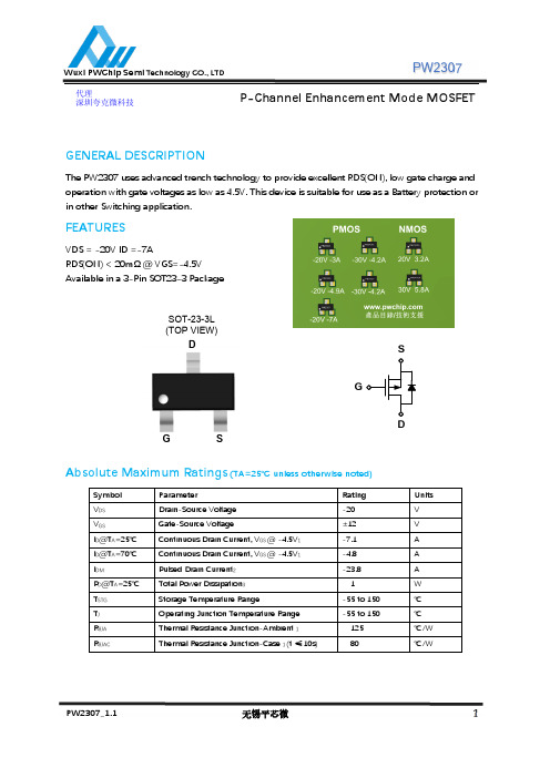
PW2307
Fig.9 Normalized Maximum Transient Thermal Impedance
Fig.10 Switching Time Waveform
Fig.11 Gate Charge Waveform
PW2307_1.1
无锡平芯微
4
Wuxi PWChip Semi Technology CO., LTD
Fig.4 Gate-Charge Characteristics
1.8 1.4 1.0 0.6
0
50
100
150
TJ , Junction Temperature (℃ ) Fig.6 Normalized RDSON vs. TJ
PW2307_1.1
无锡平芯微
3
Wuxi PWChip Semi Technology CO., LTD
0.104
0.116
0.037(BSC)
0.071
0.079
0.012
0.024
0°
8°
PW2307_1.1
无锡平芯微
5
1.500
1.700
2.650
2.950
0.950(BSC)
1.800
2.000
0.300
0.600
0°
8°
Dimensions In Inches
Min.
Max.
0.041
0.049
0.000
0.004
0.041
0.045
0.012
0.020
0.004
0.008
0.111
0.119
0.059
0.067
MP2307中文资料
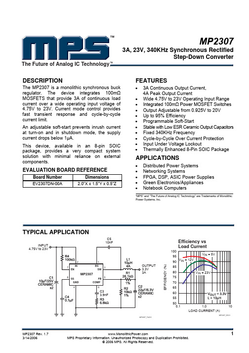
ELECTRICAL CHARACTERISTICS
VIN = 12V, TA = +25°C, unless otherwise noted.
Parameter
© 2006 MPS. All Rights Reserved.
元器件交易网
TM
MP2307 – 3A, 23V, 340KHz SYNCHRONOUS RECTIFIED STEP-DOWN CONVERTER
TYPICAL PERFORMANCE CHARACTERISTICS
© 2006 MPS. All Rights Reserved.
元器件交易网
TM
MP2307 – 3A, 23V, 340KHz SYNCHRONOUS RECTIFIED STEP-DOWN CONVERTER
PACKAGE REFERENCE
TOP VIEW
BS 1 IN 2 SW 3 GND 4
100
95 90 VIN = 12V
VIN = 5V
85
80
VIN = 23V
75
70
65
60
55
50
0.1
1.0
10
LOAD CURRENT (A)
MP2307_EC01
MP2307 Rev. 1.7
1
3/14/2006
MPS Proprietary Information. Unauthorized Photocopy and Duplication Prohibited.
IRFR2307Z资料
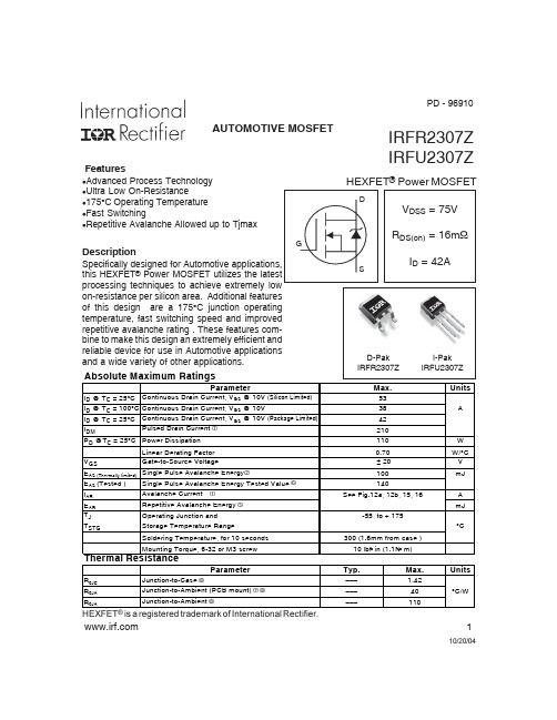
Source-Drain Ratings and Characteristics
Parameter
Min. Typ. Max. Units
Conditions
IS
Continuous Source Current
––– ––– 42
MOSFET symbol
Fig 4. Typical Forward Transconductance vs. Drain Current
3
元器件交易网
IRFR/U2307Z
C, Capacitance(pF)
4000 3000 2000
VGS = 0V, f = 1 MHZ Ciss = Cgs + Cgd, Cds SHORTED Crss = Cgd Coss = Cds + Cgd
Fig 2. Typical Output Characteristics
1000
ID, Drain-to-Source Current(Α)
100 TJ = 175°C
10
TJ = 25°C 1
VDS = 20V
≤60µs PULSE WIDTH 0.1
2
4
6
8
10
VGS, Gate-to-Source Voltage (V)
IRFU2307Z
HEXFET® Power MOSFET
D
VDSS = 75V
RDS(on) = 16mΩ
ID = 42A
S
D-Pak IRFR2307Z
I-Pak IRFU2307Z
Max. 53 38 42 210 110 0.70 ± 20 100 140
FM2307单相居民多费率

标志寄存器(59H)的 TMIF 为 RTCIF。
FM2307 单相居民多费率电能表专用芯片 技术手册
第 2 页
共 89 页
第六章 时钟控制 ...................................................................................................... 36 6.1. 介绍................................................................................................................. 36 6.2. 特性................................................................................................................. 36 6.3. 分频器设置 ...................................................................................................... 36 6.4. 时钟控制.......................................................................................................... 37 6.5. 芯片睡眠唤醒................................................................................................... 37 6.6. 推荐工作模式................................................................................................... 39
SI2307CDS中文资料
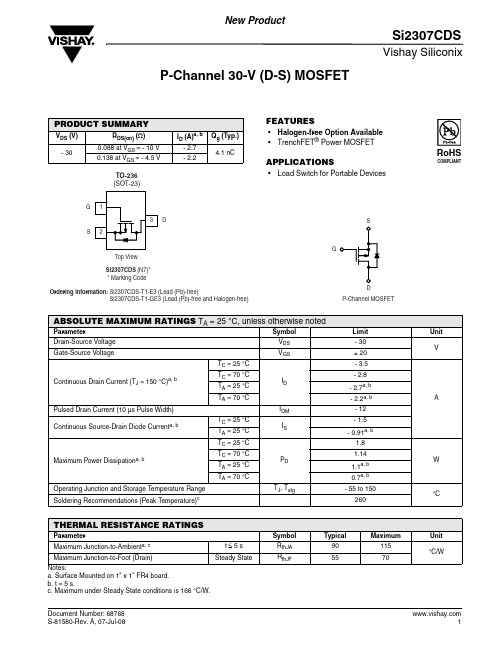
Vishay SiliconixSi2307CDSP-Channel 30-V (D-S) MOSFETFEATURES•Halogen-free Option Available •TrenchFET ® Power MOSFETAPPLICATIONS•Load Switch for Portable DevicesPRODUCT SUMMARYV DS (V)R DS(on) (Ω)I D (A)a, b Q g (Typ.)- 300.088 at V GS = - 10 V - 2.7 4.1 nC0.138 at V GS = - 4.5 V- 2.2Notes:a. Surface Mounted on 1" x 1" FR4 board.b. t = 5 s.c. Maximum under Steady State conditions is 166 °C/W. ABSOLUTE MAXIMUM RATINGS T A = 25 °C, unless otherwise notedParameter Symbol Limit nitDrain-Source Voltage V DS - 30VGate-Source VoltageV GS± 20Continuous Drain Current (T J = 150 °C)a, bT C = 25 °CI D - 3.5A T C = 70 °C - 2.8T A = 25 °C - 2.7a, b T A = 70 °C- 2.2a, b Pulsed Drain Current (10 µs Pulse Width)I DM - 12Continuous Source-Drain Diode Current a, bT C = 25 °C I S - 1.5T A = 25 °C - 0.91a, bMaximum Power Dissipation a, bT C = 25 °CP D 1.8W T C = 70 °C 1.14T A = 25 °C 1.1a, b T A = 70 °C0.7a, b Operating Junction and Storage T emperature Range T J , T stg - 55 to 150°C Soldering Recommendations (Peak Temperature)c260THERMAL RESISTANCE RATINGSParameter Symbol Typical Maximum UnitMaximum Junction-to-Ambient a, c t ≤ 5 s R thJA 90115°C/WMaximum Junction-to-Foot (Drain)Steady StateR thJF5570Vishay SiliconixSi2307CDSNotes:a. Pulse test; pulse width ≤ 300 µs, duty cycle ≤ 2 %.b. Guaranteed by design, not subject to production testing.Stresses beyond those listed under “Absolute Maximum Ratings” may cause permanent damage to the device. These are stress ratings only, and functional operation of the device at these or any other conditions beyond those indicated in the operational sections of the specifications is not implied. Exposure to absolute maximum rating conditions for extended periods may affect device reliability.SPECIFICATIONS T J = 25 °C, unless otherwise notedParameter Symbol Test Conditions Min.Typ.Max.U nitStaticDrain-Source Breakdown Voltage V DS V GS = 0 V , I D = - 250 µA- 30V V DS Temperature Coefficient ΔV DS /T J I D = - 250 µA - 32mV/°C V GS(th) Temperature Coefficient ΔV GS(th)/T J 4.5Gate-Source Threshold Voltage V GS(th) V DS = V GS , I D = - 250 µA - 1- 3VGate-Source LeakageI GSS V DS = 0 V , V GS = ± 20 V - 100nAZero Gate Voltage Drain Current I DSS V DS = - 30 V , V GS = 0 V - 1µA V DS = - 30 V , V GS = 0 V , T J = 55 °C- 10On-State Drain Current aI D(on) V DS ≤ 5 V , V GS = - 10 V - 6A Drain-Source On-State Resistance a R DS(on) V GS = - 10 V , I D = - 3.5 A 0.0730.088ΩV GS = - 4.5 V , I D = - 2.5 A 0.1100.138Forward T ransconductance a g fsV DS = - 10 V, I D = - 3.5 A7SDynamic bInput Capacitance C iss V DS = - 15 V , V GS = 0 V, f = 1 MHz340pFOutput CapacitanceC oss 67Reverse Transfer Capacitance C rss 51Total Gate Charge Q g V DS = - 15 V , V GS = - 4.5 V , ID = - 2.5 A 4.1 6.2nC Gate-Source Charge Q gs 1.3Gate-Drain Charge Q gd 1.8Gate Resistance R g f = 1 MHz10ΩTurn-On Delay Time t d(on) V DD = - 15 V, R L = 15 Ω I D ≅ - 1 A, V GEN = - 4.5 V , R g = 1 Ω4060nsRise Timet r 4060Turn-Off Delay Time t d(off) 2040Fall Timet f 1730Turn-On Delay Time t d(on) V DD = - 15 V, R L = 15 ΩI D ≅ - 1 A, V GEN = - 10 V, R g = 1 Ω 5.510Rise Timet r 1325Turn-Off Delay Time t d(off) 1730Fall Timet f7.715Drain-Source Body Diode Characteristics Continuous Source-Drain Diode Current I S T C = 25 °C- 1.5A Pulse Diode Forward Current I SM - 12Body Diode VoltageV SD I S = - 0.75 A, V GS = 0 V- 0.8- 1.2V Body Diode Reverse Recovery Time t rr I F = - 2.5 A, dI/dt = 100 A/µs, T J = 25 °C1730ns Body Diode Reverse Recovery Charge Q rr 1120nC Reverse Recovery Fall Time t a 12nsReverse Recovery Rise Timet b5On-Resistance vs. Drain Current and Gate VoltageGate ChargeCapacitanceOn-Resistance vs. Junction TemperatureSource-Drain Diode Forward VoltageThreshold VoltageOn-Resistance vs. Gate-to-Source VoltageSingle Pulse Power, Junction-to-AmbientVishay SiliconixSi2307CDSTYPICAL CHARACTERISTICS 25°C, unless otherwise notedVishay Silico nix maintains wo rldwide manufacturing capability. Pro ducts may be manufactured at o ne o f several qualified lo catio ns. Reliability data fo r Silico n Technology and Package Reliability represent a composite of all qualified locations. For related documents such as package/tape drawings, part marking, and reliability data, see /ppg?68768.Disclaimer Legal Disclaimer NoticeVishayAll product specifications and data are subject to change without notice.Vishay Intertechnology, Inc., its affiliates, agents, and employees, and all persons acting on its or their behalf (collectively, “Vishay”), disclaim any and all liability for any errors, inaccuracies or incompleteness contained herein or in any other disclosure relating to any product.Vishay disclaims any and all liability arising out of the use or application of any product described herein or of any information provided herein to the maximum extent permitted by law. The product specifications do not expand or otherwise modify Vishay’s terms and conditions of purchase, including but not limited to the warranty expressed therein, which apply to these products.No license, express or implied, by estoppel or otherwise, to any intellectual property rights is granted by this document or by any conduct of Vishay.The products shown herein are not designed for use in medical, life-saving, or life-sustaining applications unless otherwise expressly indicated. Customers using or selling Vishay products not expressly indicated for use in such applications do so entirely at their own risk and agree to fully indemnify Vishay for any damages arising or resulting from such use or sale. Please contact authorized Vishay personnel to obtain written terms and conditions regarding products designed for such applications.Product names and markings noted herein may be trademarks of their respective owners.元器件交易网。
VT-RNSII-L仕様书(中国语)
No.2152300-8B(共16页)电路板检查装置RNS系列 LS标准规格书2010年10月欧姆龙株式会社目录1.概要 (3)2.装置的外观 (3)3.装置的构成与动作 (4)3.1 装置的构成 (4)3.2 各单元的机能 (4)4.装置规格 (5)5.机能规格 (6)5.1检查对象电路板 (6)5.2检查项目 (7)5.3 检查程序 (7)5.4 电路板定位 (7)5.5 标准选择规格 (8)5.6 选择配件 (8)5.7 保护机能 (8)6.操作概要 (9)6.1 检查模式 (9)6.2 编程模式 (10)7.I/F (11)7.1 上下游I/F 信号时间图 (11)7.2 上下游连接器规格 (13)7.3 输入输出的内部连接 (14)8.本产品使用时的承诺事项 (15)9.付属品 (16)1.概要本装置是根据预先编制的“检查程序”对通过波峰焊接及回流焊接装置焊接的电路板的焊接状态(S)进行检查的装置。
在检查中使用了通过彩色高光法进行的独有的图像处理技术。
检查结果可以输出到显示器和打印机上。
并且,可将用于区分电路板合格品与不合格品的信号输出给下游装置。
2.装置的外观(单位: mm) *1 作Array*2 安装上下游电路板检知传感器(RNS2出厂标准)时,搬入搬出口处各有22mm的突起,所以横向宽度为964mm。
3.装置的构成与动作3.1 装置的构成本装置如图所示,由各个具有不同机能的单元所构成。
它们在检查中互为关联。
3.2 各单元的机能3.2.1 照相机(镜头)构成本装置的眼睛部分,采用3CCD照相机对电路板进行成像。
分辨率有10、15、20µm/三种像素。
3.2.2 显示器显示器根据主计算机的控制对检查状况及检查结果等用彩色图像进行显示。
3.2.3 主计算机依据操作人员的操作对电路板的种类做出选择并输出检查结果等,对本装置进行全体控制。
(1) HD 中预装有OS 及本装置的软件,元件库和检查程序。
APM2307中文资料
ANPEC reserves the right to make changes to improve reliability or manufacturability without notice, and advise customers to obtain the latest version of relevant information to verify before placing orders.Pin DescriptionOrdering and Marking InformationFeaturesApplicationsAbsolute Maximum Ratings (T A = 25°C unless otherwise noted)• -30V/-3A , R DS(ON)=100m Ω(typ.) @ V GS =-10VR DS(ON)=140m Ω(typ.) @ V GS =-4.5V• Super High Dense Cell Design for ExtremelyLow R DS(ON)• Reliable and Rugged • SOT-23 Package• Power Management in Notebook Computer ,Portable Equipment and Battery Powered Systems.* Surface Mounted on FR4 Board, t ≤ 10 sec.G DSTop View of SOT-23Notesa : Pulse test ; pulse width ≤300µs, duty cycle ≤ 2%b: Guaranteed by design, not subject to production testingAbsolute Maximum Ratings Cont. (T A = 25°C unless otherwise noted)Electrical Characteristics (T A = 25°C unless otherwise noted)01234524681002468102468100123456780.000.050.100.150.200.250.30-50-2502550751001251500.000.250.500.751.001.251.50Typical Characteristics-I D -D r a i n C u r r e n t (A )Transfer Characteristics-V GS - Gate-to-Source Voltage (V)Threshold Voltage vs. Junction T emperatureTj - Junction T emperature (°C)-V G S (t h )-T h r e s h o l d V o l t a g e (V )(N o r m a l i z e d )R D S (O N )-O n -R e s i s t a n c e (Ω)On-Resistance vs. Drain Current-I D - Drain Current (A)Output Characteristics-I D -D r a i n C u r r e n t (A )-V DS - Drain-to-Source Voltage (V)012345678123456789100510********-50-2502550751001251500.000.250.500.751.001.251.501.752.0002468100.00.10.20.30.40.5Typical CharacteristicsR D S (O N )-O n -R e s i s t a n c e (Ω)(N o r m a l i z e d )On-Resistance vs. Junction TemperatureT J - Junction Temperature (°C)-V DS - Drain-to-Source Voltage (V)CapacitanceC a p a c i t a n c e (p F )-V GS - Gate-to-Source Voltage (V)R D S (O N )-O n -R e s i s t a n c e (Ω)On-Resistance vs. Gate-to-Source VoltageGate ChargeQ G - Gate Charge (nC)-V G S -G a t e -S o u r c e V o l t a g e (V )1E-41E-30.010.11101000.010.110.00.20.40.60.8 1.0 1.2 1.40.1110Typical CharacteristicsP o w e r (W )Single Pulse PowerTime (sec)Square Wave Pulse Duration (sec)Source-Drain Diode Forward Voltage-I S -S o u r c e C u r r e n t (A )-V SD -Source-to-Drain Voltage (V)N o r m a l i z e d E f f e c t i v e T r a n s i e n t T h e r m a l I m p e d a n c eNormalized Thermal Transient Impedence, Junction to Ambient0.010.1110100024681012500500Packaging Information SOT-23Physical SpecificationsReflow Condition (IR/Convection or VPR Reflow)Reference JEDEC Standard J-STD-020A APRIL 1999Classification Reflow ProfilesPackage Reflow ConditionsPre-heat temperature183 CPeak temperatureTime°t e m p e r a t u r eReliability test programCarrier Tape & Reel DimensionsCover Tape DimensionsCustomer ServiceAnpec Electronics Corp.Head Office :5F, No. 2 Li-Hsin Road, SBIP,Hsin-Chu, T aiwan, R.O.C.T el : 886-3-5642000Fax : 886-3-5642050Taipei Branch :7F, No. 137, Lane 235, Pac Chiao Rd.,Hsin Tien City, Taipei Hsien, T aiwan, R. O. C.T el : 886-2-89191368Fax : 886-2-89191369。
RN-2405SP中文资料

Typical Characteristics
RN Series
RN-xx09S
Efficiency / Load
100 80 60 40
RN-xx05S
Efficiency / Load
100 80 60 40
1205
0505
0509
Efficiency %
Efficiency %
7.62
Recommended Footprint Details
7.62 7.62
1 4 Bottom View 7 5
Pin Connections Pin # 1 4 5 7 Single –Vin +Vin +Vout –Vout
1.00ø+0.15/0 2.54 ø 0.51 typ.
Top View
20 0
20 0
1209
0%
20%
40%
60%
80%
100%
0%
20%
40%
60%
80%
100%
Total Output current (%)
Total Output current (%)
Deviation / Load
25.000 20.000 25.000 20.000
Deviation / Load
5.08
2.54
XX.X ± 0.5 mm XX.XX ± 0.25 mm
July-2006
61
Deviation / Load
Deviation from Nominal (%)
15.000 10.000 5.000 0.000 -5.000 -10.000
RN2402中文资料

Characteristic
Collector-base voltage Collector-emitter voltage
Emitter-base voltage
Collector current Collector power dissipation Junction temperature Storage temperature range
元器件交易网
RN2401,RN2402,RN2403,RN2404,RN2405,RN2406
3
2001-06-07
元器件交易网
RN2401,RN2402,RN2403,RN2404,RN2405,RN2406
4
2001-06-07
元器件交易网
−1.52
−0.38
―
−0.71
−0.17
―
−0.082 ―
−0.33 mA
−0.15
−0.078 ― −0.145
−0.074 ― −0.138
30
―
―
50
―
―
70
―
―80
―
―
80
―
―
―
−0.1 −0.3
V
−1.1
―
−2.0
−1.2
―
−2.4
−1.3
―
−3.0
V
−1.5
―
−5.0
−0.6
―
―
― VCE = −0.2V ― IC = −5mA
―
―
― VCE = −5V, ― IC = −0.1mA
―
VCE = −10V, IC = −5mA
―
VCB = −10V, IE = 0 f = 1MHz
HY-2307 工业相机用户手册说明书
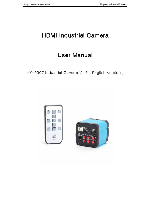
HDMI Industrial CameraUser ManualHY-2307Industrial Camera V1.2(English Version)Camera Function Instruction1.14MP Japanese Panasonic COMS sensor.2.This product has14MP snap shot image and1080P video recording.One button switchessnap shot&video mode.The default mode is shot image,press the“MODEL”button to turn to video mode,press again come to preview mode.Press on the“MODEL”button the camera will switch among shot image,video mode and preview mode.3.When the image ratio is4:3mode the photo’s resolution is4320*3240(14MP);when it is16:9mode the photo’s resolution is4320*2432(11MP).There are two preview modes as4:3 and16:9.The photo’s format is JPG.The video recording’s resolution is1920*1080frames and the format is MP4.4.The camera provides8times digital zoom,press the“UP”or“DOWN”button to zoom in andzoom out,long press to quickly zoom in or zoom out.5.This product provides HDMI video output and the output is1080P60hz.6.The product provides free drive1080P30FPS HD USB video output.7.This product supports one-key freeze/unfreeze image,when power on,press the ON/OFFbutton to achieve these functions.8.This product supports cross cursor function,there are up to5lines on horizontal andvertical which can be selected and movable,also,its color and size can be set,meanwhile it provides the center cross cursor display.9.Support auto&manual exposure;support auto&manual white balance;support colors&Black-and-White monitor mode.10.Support EV(exposure compensation)adjust.11.Support English/Francais/Espanol/Portugues/Deutsch/Italiano/Chinese/Pyccknn/Japanselanguage setting.12.Support50Hz,60hz light source frequency setting.13.Support HCSD TF card(Class4),max32GB.14.Support to save setting function after power off.Security Instruction1.When installing the equipment,please read the user manual carefully and follow theinstallation instruction,please kindly keep the manual for your reference.2.The camera power voltage is AC100V—240V@50-60Hz,please kindly make sure theparameters of your power supply is in this range.3.The standard setting of the power supply comes with the camera is12V1A,we recommendthat you use the power adapter which came together with the camera.4.The camera should be stored between0℃to50℃,using with the humidity under90%,prevent foreign object from entering the machine,do not spill liquid on the machine to prevent danger.5.Prevent knock against and violent vibration,to prevent from water in the process oftransportation,storage and installation.6.Do not attempt to disassemble the camera,there are no user serviceable parts inside.7.When clearing the camera’s shell,please use dry soft cloth,if there is too much dirt,pleaseuse a neutral detergent to wipe gently.8.If there is a gray shadow on the image,use the dust blower to blow off the dust on theoptical filter,do not use the detergent.Package IncludeHY-2307camera x1power supply x1Remote x1User manual x1Camera dust cover x1USB line x1Button Instruction1.:ON/OFF(Freeze/Unfreeze)button2.:Menu3.:Up/Zoom+4.:Down/Zoom-5.:Snap Shot/Video/OK(confirm)6.:Model/AE(switch mode)Operation Instruction1.Preparatory work1.1:Twist the cover off and install the lens.△!Noting:tear off the dust protection in front of the sensitive film before installing the lens,otherwise the image will be vague1.2:Inset the HDMI cable and DC power,when the LED light turns to blue the camera is on.1.3:When connect the camera with the computer,just plug the USB line is OK(noneed to use the power supply since USB line can power as well)nguage choose(take Chinese as example)2.1:Press the“MENU”button to enter the main menu,then press the“DOWN”button till thelanguage setting is highlight,press the“OK”button to enter the language setting and press the“DOWN”button to choose the Chinese,then press the“OK”button to return to the main menu.3.Line setting3.1:Under the main menu,select the line setting,press the“OK”button to enter the line settingmenu.3.2:Press the“DOWN”and“UP”button to choose the setting selection you need.3.3:When the cross hair is highlight,press the “OK”button to open or close the cross hair.3.4:Cross Hair Setting(1)Cross HairPress the“OK”button to open the Cross Hair setting,the Cross Hair will be displayed on the middle part of the screen,press the“OK”button to switch ON and OFF,ON means display the cross hair and OFF means hide it.(2)LinePress the“OK”button,it will decrease from10-1-OFF,1means the first line,and so on. (3)DirectionPress the“OK”button,it will cycle among HOR-OFF-VER,HOR means horizontal line,VER means vertical line and OFF means turn off the line.(4)PositionPress the“OK”button,it will decrease from959-0.Long press on the“OK”button it will decrease rapidly and long press the“MODE”button it will increase rapidly.The value of the HOR smaller it will site more to left and when it increases it will site more to right,the value of VER smaller it will site more upward and when it increases it will site more downward.(5)Line ColorPress the“OK”button,there are7colors to choose:GREEN-RED-WHITE-BLACK-TRANS-ORANGE-BLUE.(6)Line WeightPress the“OK”button,it will cycle among5-4-3-2-1,1means the minimum line and5means the thickest line.4.Exposure+2.0+5/3+4/3+1.0-2/3+1/3+0.0-1/3-2/3-1.0-4/3-5/3-2.0.press the“UP”or“DOWN”button to choose the exposure option then press the“OK”button to enter the exposure setting.5.White Balance SettingPress the“MENU”button to open the main menu,press the“DOWN”button to choose the white balance,then press“OK”button to enter the white balance setting,press the“OK”or “MODEL”button to set white balance you want.the new version has added manual white balance.6.Color SettingPress the“MENU”button to open the main menu,press the“DOWN”button when it goes to the color option and press the“OK”button to enter the color setting menu,press the“UP”or “DOWN”button to switch color mode and black&white mode,press“OK”button when youare sure.Press the“MENU”button you can turn back to the main menu.7.FrequencyPress the“MENU”button to open the main menu,press the“DOWN”button to choose thefrequency option then press“OK”button to enter the frequency,press the“UP”or“DOWN”button to switch50Hz or60Hz,press the“OK”button when you are sure.Press the“MENU”button to turn back to the main menu.8.Format TF cardPress the“MENU”button to open the main menu,then press the“DOWN”button,when it goes to Format,press the“OK”button to select it.Press the“UP”or“DOWN”button to select cancel or confirm.When select confirm and press“OK”button the TF card will be formatted.Noting:all data will be deleted after the TF card been formatted,please make sure there is acopy before you do it.9.Date and Time settingPress the“MENU”button to open the main menu,press the“DOWN”button to the data andtime setting option and press“OK”button to select.press the“OK”button to switch the itemyou need to set(eg:year,month and day),when the changed item turns on red,press the“UP”or“DOWN”button to adjust,after adjustment press the“MENU”button to save andturn back to main menu.10.System settingPress the“MENU”button to open the main menu,press the“DOWN”button to the default setting option and then press“OK”button to enter the setting page.Select the confirm itwill return menu setting to defaults.Select cancellation it will exit.11.Freeze/UnfreezePress on the ON/OFF button,the image will freeze,and there is a signal in the left downcorner of the image(as shown below),press again it will unfreeze and the signal willdisappear.12.ON/OFFLong press on the ON/OFF button to turn on when the camera is off.Long press on the ON/OFF button to turn off when the camera is on.13.Electronic amplification and reduction13.1:Press the“UP”button the image will electronic amplification,the multiple will beshowed on the left of the image,the maximum multiple up to8times and image will be vague when magnification.13.2:After electronic amplification,press on the“DOWN”button the image will reduction,the multiple will be shown on the left of the image and it can reduce to the original size. 14.Switch photo and video mode14.1:The system default is photo mode,press the“OK”button to take photo.14.2:Press the“MODEL”button to switch video mode,press the“OK”button to startcapturing and press“OK”button again to stop recording.Remote Control and Key Operation InstructionS-EYE User ManualOverviewS-EYE is an application for imaging a dynamic image processing,has the following characteristics:1.Support a variety of cameras,can switch at any time to use.ing GPU rendering for image previewing,support for live image display of high-resolutionand high frame rates.3.Support dynamic image measurement function.4.The software interface is easy to operate.User Interface1.Toolbar:Take pictures/Recording video/Browse files.2.Sidebar tab:Switching the rightmost control panels,currently provides camera control andmeasurement functions.3.Control panel:Specific camera control and measurement operations.4.Status bar:Display camera information,Change user interface view,Toggle measure resultpanel.5.Main menu:Open setting dialog,show software information,etc.Capture ImagesYou can capture pictures and videos:1.Take a picture:Click“Snap”button to take a picture.Click the right arrow beside the“Snap”button to set picture file format and resolution.2.Recording:Click“Record”button to start video recording,Click again to stop recording.Whenrecording,there will be an animation indicator over the image.3.Browse:Click“Browse”button to open the folder where pictures and video stored.Camera ControlScreen shot DescriptionDevice Control:●Select a camera currently connected.●Set preview size and image format.Exposure and Gain:●Toggle automatic and manual exposurecontrol.●Change exposure time.●Change gain value.●Change auto exposure target brightness.not be operated. Measurement IconHot KeysTake a capture ENTERStart or stop recording F9Enter or exit full screen mode F11 TroubleshootingProblem SolutionSome parts of the preview image is blank, some parts is normal.Possibly the graphics drivers may not be installed,please install the latest graphics drivers.How to define the measurementTake a5mm measurement as example1.Fill in a custom name2.Fill in the actual size on the scale3.Choose the scale base(such as:px,cm,mm,um,in,uin)plete the setting5.The below picture shows the5mm measurement resultThank you for your support!Please kindly leave us a positive feedback after receiving the goods! For more product messages and manual,please kindly download from the official website of our company。
- 1、下载文档前请自行甄别文档内容的完整性,平台不提供额外的编辑、内容补充、找答案等附加服务。
- 2、"仅部分预览"的文档,不可在线预览部分如存在完整性等问题,可反馈申请退款(可完整预览的文档不适用该条件!)。
- 3、如文档侵犯您的权益,请联系客服反馈,我们会尽快为您处理(人工客服工作时间:9:00-18:30)。
TOSHIBA Transistor Silicon PNP Epitaxial Type (PCT Process)RN2307,RN2308,RN2309Switching, Inverter Circuit, Interface Circuit And Driver Circuit Applicationsl With built-in bias resistors l Simplify circuit designl Reduce a quantity of parts and manufacturing process l Complementary to RN1307~RN1309Equivalent Circuit Bias Resistor ValuesMaximum Ratings (Ta = 25°C)Characteristic Symbol RatingUnitCollector-base voltage V CBO −50 V Collector-emitter voltageV CEO−50 V RN2307−6 RN2308 −7 Emitter-base voltageRN2309V EBO −15VCollector currentI C −100 mACollector power dissipation P C 100 mW Junction temperature T j 150 °C Storage temperature rangeT stg−55~150°CJEDEC ―EIAJ SC-70 TOSHIBA 2-2E1A Weight: 0.006gType No.R1 (k Ω)R2(k Ω)RN2307 10 47 RN2308 22 47 RN2309 4722Unit: mmElectrical Characteristics (Ta = 25°C)Characteristic SymbolTestCircuitTest ConditionMin Typ. Max Unit I CBO ― V CB = −50V, I E = 0 ― ― −100Collector cut-off currentI CEO― V CE = −50V, I B = 0 ― ― −500nARN2307― V EB = −6V, I C = 0 −0.081 ― −0.15RN2308 ― V EB = −7V, I C = 0 −0.078 ― −0.145Emitter cut-off currentRN2309 I EBO ―V EB = −15V, I C = 0−0.167―−0.311mA RN2307― 80 ― ― RN2308 ― 80 ― ― DC current gainRN2309h FE ― V CE = −5V, I C = −10mA 70 ― ― ― Collector-emitter saturation voltageV CE (sat) ― I C = −5mA, I B = −0.25mA― −0.1 −0.3VRN2307― −0.7 ― −1.8RN2308 ― −1.0 ― −2.6Input voltage (ON)RN2309 V I (ON) ― V CE = −0.2V, I C = −5mA −2.2 ― −5.8V RN2307― −0.5 ― −1.0RN2308 ― −0.6 ― −1.16Input voltage (OFF)RN2309V I (OFF) ― V CE = −5V, I C = −0.1mA −1.5―−2.6V Translation frequency f T ― V CE = −10V, I C = −5mA ― 200 ― MHz Collector output capacitanceC ob ―V CB = −10V, I E = 0,f = 1MHz― 3 6 pFRN2307― 7 10 13RN2308 ― 15.4 22 28.6Input resistorRN2309 R1 ―― 32.9 47 61.1k Ω RN2307― 0.191 0.213 0.232RN2308 ― 0.421 0.468 0.515Resistor ratioRN2309R1/R2 ―― 1.92 2.14 2.35―Type Name MarkingRN2307RN2308RN2309· TOSHIBA is continually working to improve the quality and reliability of its products. Nevertheless, semiconductor devices in general can malfunction or fail due to their inherent electrical sensitivity and vulnerability to physical stress. It is the responsibility of the buyer, when utilizing TOSHIBA products, to comply with the standards of safety in making a safe design for the entire system, and to avoid situations in which a malfunction or failure of such TOSHIBA products could cause loss of human life, bodily injury or damage to property.In developing your designs, please ensure that TOSHIBA products are used within specified operating ranges as set forth in the most recent TOSHIBA products specifications. Also, please keep in mind the precautions and conditions set forth in the “Handling Guide for Semiconductor Devices,” or “TOSHIBA Semiconductor Reliability Handbook” etc.. · The TOSHIBA products listed in this document are intended for usage in general electronics applications (computer, personal equipment, office equipment, measuring equipment, industrial robotics, domestic appliances, etc.). These TOSHIBA products are neither intended nor warranted for usage in equipment that requires extraordinarily high quality and/or reliability or a malfunction or failure of which may cause loss of human life or bodily injury (“Unintended Usage”). Unintended Usage include atomic energy control instruments, airplane or spaceship instruments, transportation instruments, traffic signal instruments, combustion control instruments, medical instruments, all types of safety devices, etc.. Unintended Usage of TOSHIBA products listed in this document shall be made at the customer’s own risk. · The information contained herein is presented only as a guide for the applications of our products. No responsibility is assumed by TOSHIBA CORPORATION for any infringements of intellectual property or other rights of the third parties which may result from its use. No license is granted by implication or otherwise under any intellectual property or other rights of TOSHIBA CORPORATION or others. · The information contained herein is subject to change without notice.000707EAARESTRICTIONS ON PRODUCT USE。
