MAX1771及其在DC-DC转换器中的应用
MAX471MAX472的中文资料大全
M A X471M A X472的中文资料大全(总4页)-本页仅作为预览文档封面,使用时请删除本页-MAX471/MAX472的特点、功能美国美信公司生产的精密高端电流检测放大器是一个系列化产品,有MAX471/MA X472、 MAX4172/MAX4173等。
它们均有一个电流输出端,可以用一个电阻来简单地实现以地为参考点的电流/电压的转换,并可工作在较宽电压内。
MAX471/MAX472具有如下特点:●具有完美的高端电流检测功能;●内含精密的内部检测电阻(MAX471);●在工作温度范围内,其精度为2%;●具有双向检测指示,可监控充电和放电状态;●内部检测电阻和检测能力为3A,并联使用时还可扩大检测电流范围;●使用外部检测电阻可任意扩展检测电流范围(MAX472);●最大电源电流为100μA;●关闭方式时的电流仅为5μA;●电压范围为3~36V;●采用8脚DIP/SO/STO三种封装形式。
MAX471/MAX472的引脚排列如图1所示,图2所示为其内部功能框图。
表1为MAX471/MAX472的引脚功能说明。
MAX471的电流增益比已预设为500μA/A,由于2kΩ的输出电阻(ROUT)可产生1V/A的转换,因此±3A时的满度值为3V.用不同的ROUT电阻可设置不同的满度电压。
但对于MAX471,其输出电压不应大于VRS+。
对于MAX472,则不能大于。
MAX471引脚图如图1所示,MAX472引脚图如图2所示。
MAX471/MAX472的引脚功能说明引脚名称功能MAX471MAX47211SHDN关闭端。
正常运用时连接到地。
当此端接高电平时,电源电流小于5μA2,3-RS+内部电流检测电阻电池(或电源端)。
“+”仅指示与SIGN输出有关的流动方向。
封装时已将2和3连在了一起-2空脚-3RG1增益电阻端。
通过增益设置电阻连接到电流检测电阻的电池端44GND地或电池负端55SIGN集电极开路逻辑输出端。
MAX1771ESA+中文资料
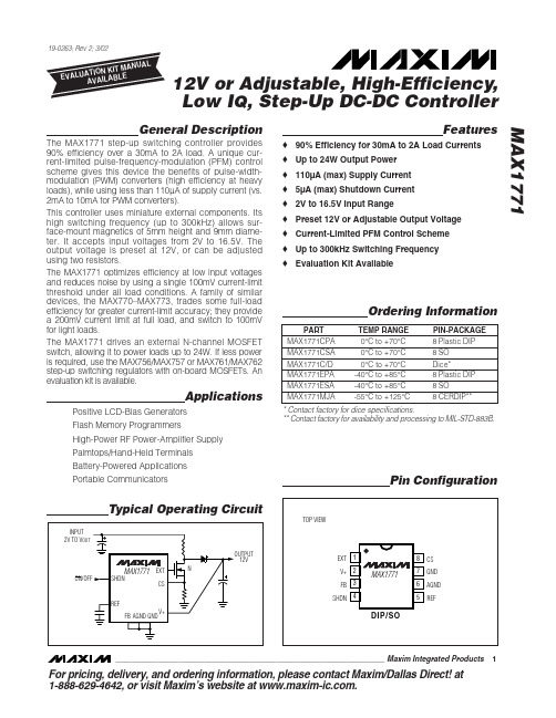
MAX1771
Ordering Information
PART MAX1771CPA MAX1771CSA MAX1771C/D MAX1771EPA MAX1771ESA MAX1771MJA TEMP RANGE 0°C to +70°C 0°C to +70°C 0°C to +70°C -40°C to +85°C -40°C to +85°C -55°C to +125°C PIN-PACKAGE 8 Plastic DIP 8 SO Dice* 8 Plastic DIP 8 SO 8 CERDIP**
ELECTRICAL CHARACTERISTICS
(V+ = 5V, ILOAD = 0mA, TA = TMIN to TMAX, unless otherwise noted. Typical values are at TA = +25°C.) PARAMETER Input Voltage Range Minimum Start-Up Voltage Supply Current Standby Current Output Voltage (Note 1) Output Voltage Line Regulation (Note 2) Output Voltage Load Regulation (Note 2) Maximum Switch On-Time Minimum Switch Off-Time Efficiency tON(max) tOFF(min) V+ = 5V, VOUT = 12V, ILOAD = 500mA, Circuit of Figure 2a MAX1771C Reference Voltage VREF IREF = 0µA MAX1771E MAX1771M REF Load Regulation REF Line Regulation FB Trip Point Voltage VFB 0µA ≤ IREF ≤ 100µA 3V ≤ V+ ≤ 16.5V MAX1771C MAX1771E MAX1771M 1.4700 1.4625 1.4550 MAX1771C/E MAX1771M 1.4700 1.4625 1.4550 V+ = 16.5V, SHDN = 0V (normal operation) V+ = 10V, SHDN ≥ 1.6V (shutdown) V+ = 16.5V, SHDN ≥ 1.6V (shutdown) V+ = 2V to 12V, over full load range, Circuit of Figure 2a V+ = 5V to 7V, VOUT = 12V ILOAD = 700mA, Circuit of Figure 2a V+ = 6V, VOUT = 12V, ILOAD = 0mA to 500mA, Circuit of Figure 2a 12 1.8 11.52 SYMBOL CONDITIONS MAX1771 (internal feedback resistors) MAX1771C/E (external resistors) MAX1771MJA (external resistors) MIN 2.0 3.0 3.1 1.8 85 2 4 12.0 5 12.48 TYP MAX 12.5 16.5 16.5 2.0 110 5 V µA µA V mV/V V UNITS
MAX1771 12V或可调高效率升压型DC

MAX1771 12V或可调高效率升压型DC-DC控制器IC电路特点及应用原理图介绍文章来源:更新时间:2010-12-25 12:19:00MAX1771控制芯片简介MAX1771采用BiCOMOS工艺制造,该控制器采用独特的控制方案,结合PFM(脉冲频率调制)及PWM(脉冲宽度调制)的优越性,提供一个高效、较宽电压调节范围的电源。
前者具有较小的静态电流,轻载情况下效率较高,但纹波较大。
后者在重载情况下具有较高的效率,噪声小。
该控制器采用的是一种改进型的限流PFM控制方式,控制电路限制电感充电电流,使其不超过某一峰值电流。
既保持了传统PFM的低静态电流,同时在较重负载下也具有很高的效率,而且由于限制了峰值电流,采用很小体积的外围元件就可获得满意的输出纹波,这样便于降低电路成本及电路的尺寸。
MAX1771极限参数:供应电压UitoGND0.3V~17V工作温度存储温度-65℃~+160℃MAX1771C-A0℃~+70℃焊接温度(10秒)300℃MAX1771E-A-40℃~+70℃Ui工作范围2V~16.5VMAX1771MJA-55℃~+125℃MAX1771引脚功能说明:MAX1771的引脚如图2所示:引脚功能说明:1脚EXT:栅极驱动,接N沟道功率管。
2脚V+:电源电压输入端,(正端)。
3脚FB:调节输出电压信号的反馈输入,接地为固定输出电压,接电阻分压器调节输出电压。
4脚SHDN:关断模式的关断输入,接地为正常操作。
5脚REF:对于外接负载是100μA的1.5V参考电压输出。
6脚AGND:模拟信号地。
7脚GND:从输出驱动器返回的大电流地。
8脚CS:该点电位传送到内部电流传感器的放大器,将电流传感器电阻接到CS和GND 之间。
应用/使用•电池供电应用•闪存编程•大功率射频功放电源•掌上电脑/手持终端•便携式通信装置•LCD正偏置发生器应用电路原理图。
MAX17502同步降压DCDC转换器
MAX17502同步降压DC/DC转换器MAX17502 ,MAX17502高效率,高电压,同步降压型的DC-DC转换器工作在4.5V 至60V的输入电压范围和设计应用范围广。
超宽输入操作,使得它不仅为工业控制和楼宇自动化的理想,但也基站,家庭娱乐,电信和汽车应用。
它提供高达1A的输出电流超过3.3V 和5V的输出电压的温度。
输出电压范围内随温度的±1.6%准确。
器件工作在-40°C至+125°C 的工业温度范围内,在一个微小的,10针(3毫米×2毫米)的TDFN无铅(Pb)免费包带有裸焊盘。
该器件具有峰值脉冲宽度调制(PWM)电流模式控制。
PWM操作,确保在所有操作条件下的恒定开关频率。
低电阻,片上,PMOS / NMOS开关,确保在满负荷高效率,同时最大限度地减少关键的电感,使布局更简单的任务,与分立式解决方案相比,该器件提供固定开关频率为600kHz。
为了降低输入浪涌电流,该器件提供SS引脚与一个外部电容器地面可调电压软启动功能。
该器件还集成了一个输出使能/欠压锁定引脚(EN / UVLO)功能,允许用户打开部分所需的输入电压水平。
漏极开路,低电平有效的RESET引脚提供了一个延迟的电源良好信号系统实现成功调节输出电压时。
该设备支持低功耗的打嗝模式限流,过载,输出短路条件下的保护。
关键特性消除外部元件,并降低总成本没有高效率和降低成本的肖特基同步操作超紧凑布局的内部补偿全陶瓷电容器DC-DC稳压器的数量减少股票4.5V至60V的宽工作电压范围固定3.3V和5V输出在整个温度范围内提供高达1A600kHz的开关频率降低功耗最高效率> 90%关断电流1μA(典型值)运行可靠,在恶劣的工业环境打嗝模式电流限制与自动重启动内置监测输出电压(漏极开路,低电平有效RESET引脚)电阻可编程UVLO阈值具有可调软启动和预偏置电源,最多增加安全可选的可调输出和PFM(可根据工厂要求)-40°C至+125°C工业温度范围(本文转自电子工程世界:/dygl/2012/1218/article_15254.html)。
MAX1674中文

高效率升压式DC-DC电源转换器MAX1674/MAX16751MAX1676
类别:电源技术阅读:1205
MAX1674,MAX1675,MAX1676是MAXIM公司生产的高效率、低功耗、升压式DC-DC转换器。
(1)特性
MAX1674,MAX1675, MAX1676是升压式DC-DC电源转换器,常态下工作效率可达94%,输入电压范围较宽(0.7---5.5 V),输出电压则可设定为5V,允许的输出电流达到500mA。
MAX1674, MAX1675 , MAX1676的静态电流仅16μA,在输出200 mA时效率可达94%,在关闭电源时,耗电仅为0.1μA,并可选择电流限制来降低纹波电压。
(2)内部电路与引脚功能
MAX1674,MAX1675采用8引脚μMAX封装形式,MAX1676则采用10引脚拌MAX封装形式。
其内部电路框图如图所示,各引脚功能见表.
(3)应用电路
MAX1674,MAX1675,MAX1676非常适用于1-3节电池供电的手持设备、笔记本电脑、医疗设备、寻呼机PDA,无线电话、 MP3播放器等。
MAX1674, MAX1675, MAX1676的典型应用电路如图所示。
MAX1771CSA中文资料

8 SO Dice* 8 Plastic DIP 8 SO 8 CERDIP**
* Contact factory for dice specifications. ** Contact factory for availability and processing to MIL-STD-883B.
MIN
MAX1771 (internal feedback resistors)
2.0
Input Voltage Range
MAX1771C/E (external resistors)
3.0
MAX1771MJA (external resistors)
3.1
Minimum Start-Up Voltage Supply Current
8 CS 7 GND 6 AGND 5 REF
________________________________________________________________ Maxim Integrated Products 1
For pricing, delivery, and ordering information, please contact Maxim/Dallas Direct! at 1-888-629-4642, or visit Maxim’s website at .
Operating Temperature Ranges MAX1771C_ A .....................................................0°C to +70°C MAX1771E_ A ..................................................-40°C to +85°C MAX1771MJA ................................................-55°C to +125°C
用MAX1771(MAX770)制作万用表9V电源(万用表代用电源)

用MAX1771(MAX770)制作万用表9V电源(万用表代
用电源)
之前曾经做了几个万用表代用电源,但是效果不太理想,网上的电路也很多,用三极管搭建,电路很简单,很多电路都需要一个电源开关来控制,否则电池很不耐用,没几天就没电了。
手头上有限制的芯片MAX770,现在这个芯片已经停产了,代替的型号是MAX1771,两个芯片使用是一样的,可能芯片本身有点区别,但是我用在电路上看不出来。
MAX1771的datasheet上有很多电路,要制作万用表电源,直接抄上面的电路就可以了,我就是抄的,不过由于没有毫欧级的电阻,所以我取消了原本接在芯片CS引脚上的电阻,直接将CS引脚接地,可能会给电路的稳定性带来影响,另外,没有这个电阻,这个电路输出电流会很大,如果有意外发生,那问题就大了。
我的电路如下:
我的这个万用表代用电源没有设置开关,如果你需要设置开关,就将开关串联到电路里就可以了。
这个电路耗电很小,在万用表关闭的时候,耗电为0.7毫安,我使用的锂电池是2800毫安时,所以我就不做开关了,理论上,这个电路在万用表关闭情况下,待机可以长达166天。
即使是万用表打开的情况下,电源的消耗也不多,只有23毫安。
当然,这个锂电池是我在路上捡到的,不知道是哪种手机上用的,上面标称。
MAX1771及其在DC-DC转换器中的应用

MAX1771及其在DCDC--DC转换器中的应用Maxim公司北京办事处徐继红MAX1771是MAXIM公司出品的一种DC-DC转换器控制芯片可用于多种不同形式的DC-DC转换电路它采用BiCMOS工艺制造因此兼有低功耗与高开关频率的特点正常工作电流不超过110A进入停机状态时功耗可降低至5A以内开关频率可高达300kHz因此可采用体积很小的外部功率元件整个DC-DC转换器尺寸可以做得非常小另外器件内部集成了多种DC-DC转换器所需的功能单元外围电路非常简单可以很容易地用它设计出满足不同需要的DC-DC转换器1MAX1771的内部结构如图1所示MAX1771的内部结构可划分为以下几个功能单元限流型PFM控制单元内部反馈网络低电压启动电路停机控制电路等下面分别对其结构及工作原理作一简要论述图1. MAX1771结构框图11限流型 PFM控制单元包括U1U2U3U4它是DC-DC控制器的中心环节完成对输出电压及电感电流的检测并根据检测结果对外部功率开关进行控制以达到稳定输出电压的目的其中U1为1.5V基准电压U2为误差比较器二者相配合完成对输出电压的检测U3为电流检测放大器用来检测电感受电流U4为PFM控制逻辑它根据电压电流检测结果对外部功率开关进行控制它还具有最小关断时间最大导通时间控制以便使DC-DC转换器安全可靠地工作由图可见当开关处于关断状态时控制电路只在以下两个条件同时满足时才打开外部功率开关对电感充电最小关断时间到达采样点电压低于 1.5V当开关处于导通状态时下面两种情况之一的出现则使开关关断最大导通时间到达电感电流达到预定门限12内部反馈网络由R1R2N及方式比较器U5组成当将FB引脚接至地电平时方式比较器将电路切换至内部采样方式采样电压由R1R2分压获得R1R2的比值决定了输出为+12V当FB处于高于50mV的电平时则关闭内部采样由外部采样电路取得反馈电压以便获得不同的输出电压13低电压启动电路由低电压振荡器U6电压比较器U7及切换开关构成用于在电源电压较低的情况下使DC-DC转换器启动工作低压振荡器具有固定的50%占空比当V+端电压高于2.5V后则切换至PFM控制方式14停机控制电路当不需要DC-DC输出时该电路可使控制器处于功耗极低的停机方式在该方式下耗电低于5A外部开关处于关断状态通过给控制引脚SHDN施加一个电平信号就可使电路进入低功耗停机方式该引脚输入低电平VIL0.4V时处于工作状态当输入高电平V IH 1.6V时则进入停机方式2MAX1771的典型应用电路MAX1771的典型应用电路如图2所示该电路为升压结构可以由2V至12V的输入电压得到一个稳定的12V输出电压该电路能否正常工作以及其转换效率输出纹波等性能与外部元件的选择有很大关系下面简单讨论一下几个主要功率元件的选择问题图2. MAX1771典型应用电路由5V输入升压至12V2.1 电感的选择电感L1应选用直流电阻较低饱和电流较大的功率电感这种电感一般为缠绕在铁氧体磁芯上的线圈当流经电感的电流较大时由于磁芯的饱和将使实际电感值下降所以应选用饱和电流较大大于实际流过电感的峰值电流的电感一般来讲20%的轻度饱和电感量下降20%是可以接受的电感值一般可在10H至300H之间选择过小的电感量将会使电感电流不连续造成电流输出能力降低输出纹波增大并有可能在限流比较器关断功率开关之前使电感电流增加到很大值而造成DC-DC转换器的损坏电感值过大则会造成瞬间响应变差并增加DC-DC转换器体积电感值的选取应当以实际输入输出条件及对输出纹波瞬态相应等的要求为依据下面就以图2为例说明如何选择电感参数图2电路的输入输出条件为输入电压 V IN =5V输出电压 V OUT=12V输出电流 I OUT=500mA最大工作频率F max=300kHz另外要求在额定输出电流时电感电流脉动的峰峰值I=0.5A电感峰值电流的计算步骤如下A 计算占空比D=VOUT-V IN/V OUT=58.3%B 计算平均电感电流ILavb=I OUT/1-D=1.2AC 计算电感峰值电流I LP= I Lavb +I/2=1.45AD 计算电感值L VIN D/(IXF max)=19.4H则可以选取饱和电流不低于 1.45A电感值20H左右的电感例如Coilcraft公司的DO3308P-223或DS3316P-223型就可使用2.2 功率开关的选择功率开关须选用功率MOSFET其主要参数有开启电压V TH漏-源击穿电压V(BR)DSS沟道导通电阻R DS漏极电流I D等一般应选用开启电压较低导通电阻较小的MOSFET例如International Rectifier公司出品的可工作于逻辑电平的HEXFET Power MOSFET系列产品当其被关断时所承受有最大漏源电压为V DSP=V OUT V BR DSS至少应高于此值一般还应考虑留有一定的安全裕量另外一个需要考虑的参数就是漏极电流I D该值一般应高于电感峰值电流I LP 至于沟道电阻R DS及开启电压V TH在条件允许的情况下应选用尽量低的值2.3 续流二极管D的选择为提高转换效率该器件应选用正向导通压降较低的肖特基二极管其主要参数为最大反向电压V R及最大正向电流I D当功率开关导通时D所承受的最大反向电压为V R=V OUT功率开关关断后流经电感的峰值电流I LP全部流过D成为续流二极管的最大峰值电流I DP=I LP2.4 电流检测电阻R SENSE的选择器件内部的电流检测比较器通过检测R SENSE上的电压降并将其与内部0.1V的参考电压进行比较以限制流过电感的峰值电流由前面的计算电感峰值电流为I LP=1.45A故应选取R SENSE=0.1V/1.45A=0.0693用MAX1771构杨其它类型的DC-DC转换器用MAX1771不仅可以构成升压型DC-DC转换器还可以根据实际需要构成其它类型的DC-DC 转换器例如SEPIC flyback cuk等不同应用除主回路接法不同外控制回路基本相同下面分别进行讨论3.1 可完成升/降压转换的SEPIC当所需电压正好落在输入电压范围之间时就无法采用单纯的升压或降压转换得到这时可以考虑采用如图3.所示的可完成升/降压转换的SEPIC电路该电路转换效率比图2电路稍低可接近于80%左右原因是主回路上的元件数增加了但它能够在输入电压变化范围很大的情况下以较高的效率转换得到一个稳定的输出例如当需要由4节电池的输入得到5V输出的情况下就可考虑采用此种电路图3 可完成升/降压转换的SEPIC转换电路3.2 flyback电路如图4. 所示这种电路的优点是可以保持占空比在最佳范围内的情况下可通过改变高频变压器的原副边绕组的匝数比使得DC-DC转换器工作在最佳状态下另外还可以通过在高频变压器上增加绕组以获得多组输出电压3.3 cuk电路如图5. 所示这种电路可以由正电源得到一个负电源而且其纹波可以做得非常小若将两只储能电感L1和L2绕在同一磁芯上适当选择其匝比耦合系数及其绕制方向就能使输出的纹波电流被完全抵消做到零纹波输出3.4 由-48V输入得到+5V电源的电路如图6. 所示该电路可由高达-48V的负电源得到一个+5V电源电路中的Q2D2R5R6为MAX1771的V+端提供了一个相对于地的正电源约为9.4V R2R3R4及Q3为反馈网络R7R9C8D3构成一个软启动电路图4 用MAX1771控制的flyback DC-DC变换电路图5 由MAX1771构成的cuk型DC-DC电路图6 由-48V输入获得+5V电源的电路参考文献(1) New Releases Data Book. MAXIM, 1995(2) Coilcraft Inductors Transformers Filters(3) 叶治政叶靖国开关稳压电源高等教育出版社(4) 何希才新型开关电源及其应用人民邮电出版社。
8位AD转换器MAX113_MAX117的原理及应用

器件应用8位AD转换器M AX113/M AX117的原理及应用上海交通大学(上海200030)汤同奎邵惠鹤摘要MAX113/MAX117是MAXIM公司新近推出的8位AD转换器,它们采用单一+3V 供电,不需外接时钟,内带采样保持器,特别适合于低电压供电的低功耗系统。
文章简要介绍了M AX113/MAX117的基本原理。
首先对它们的功能、特点及应用场合作了简单说明,然后介绍了它们的引脚功能、转换原理以及读写时序,提出了对模拟量的几点考虑,最后给出了一个基于M AX113便携式数据采集器设计的应用实例。
关键词模数转换AD转换器节电方式数据采集1概述M AX113/MAX117是与微处理器兼容的8位AD转换器,MAX113有4个输入模拟通道, M AX117有8个输入模拟通道,它们均采用单一+ 3V供电,不需要外接时钟,内带采样保持器。
芯片内部采用半闪烁(hal-f flash)技术使得进行一次转换仅需1.8L s。
PWRDN为低电平时芯片功耗可降至1L A典型值。
器件由节电方式返回正常工作方式的时间小于900ns,采用突发方式可大大减少供电电流,这是因为在突发方式中,AD转换器在指定的时间间隔从低功耗状态被唤醒去采集输入模拟信号。
M AX113/MAX117内部都有采样保持器,容许AD 转换器接受快速变化的模拟信号。
M AX113/MAX117与微处理器的接口非常简单,无需外加接口电路,既可采用存储器映像编址,也可采用I/O端口编址。
数据输出带锁存和三态缓冲电路,它们可直接与8位L P数据总线或输入端口相连。
可实现输入电压相对于参考电压的比率测量。
四通道MAX113采用24脚封装,八通道的M AX117采用28脚封装。
M AX113/MAX117可广泛应用于电池供电系统、便携式设备、系统监视、远程数据采集及通信系统等。
2引脚说明M AX113引脚图如图1所示,MAX117引脚图如图2所示。
各引脚功能说明如下:图1M AX113引脚图图2M AX117引脚图D0~D7为三态数据输出。
常用功放升压ic

常用功放升压ic功放升压 IC(Integrated Circuit)是一种集成了升压功能的电路芯片,通常用于提升电源电压以满足某些电子设备的要求。
以下是一些常用的功放升压 IC:LM2577/LM2577T系列:* 制造商: National Semiconductor(现在是德州仪器 - Texas Instruments)* 特点:调节式升压稳压器,可提供可调输出电压。
MT3608:* 制造商: Monolithic Power Systems* 特点: 2A DC-DC 升压模块,适用于小型电源升压应用。
XL6009:* 制造商: XLSemi(杰力半导体)* 特点:可调升压 DC-DC 转换器,适用于多种应用,例如电子设备和 DIY 电源。
MAX1771:* 制造商: Maxim Integrated* 特点:高效、低成本、可调的升压 DC-DC 转换器,适用于电池供电设备。
TPS61200:* 制造商: Texas Instruments* 特点:低功耗、高效率的 1.8V 至 5.5V 输入电压范围的升压转换器。
LT1370:* 制造商: Linear Technology(现在是ADI - AnalogDevices)* 特点:高效率的升压 DC-DC 转换器,适用于工业和通信应用。
ADM7150:* 制造商: Analog Devices* 特点:高性能低压差稳压器(LDO)和升压 DC-DC 转换器的组合。
UC3843:* 制造商: ON Semiconductor* 特点: PWM 控制的升压 DC-DC 转换器控制器。
这些 IC 提供了不同的电压升压范围、电流容量和特性,以满足各种应用的需求。
选择合适的功放升压 IC 取决于具体的设计要求和应用场景。
dcdc转换器工作原理

dcdc转换器工作原理
DC-DC转换器是一种用来将电源输出的直流电转换成不同电压、电流或功率的装置。
其工作原理基于开关电源技术。
DC-DC转换器包含一个输入端、一个输出端和一个功率开关。
当输入电压施加在输入端时,功率开关会周期性地打开和关闭。
当开关关闭时,输入电压通过电感储存能量,形成电感电流。
当开关打开时,储存在电感中的能量被释放到输出端,产生输出电压。
具体来说,当功率开关关闭时,输入电压被施加在电感上,并导致电感电流逐渐上升。
此时,电容会储存能量,并提供给输出端。
当功率开关打开时,电感中的能量被释放到电容器和输出端,产生稳定的输出电压。
为了减小输出电压的波动和提高效率,DC-DC转换器通常会
添加输出滤波电路和控制电路。
输出滤波电路用于平滑输出电压,减小电压波动。
控制电路用于监测输出电压,并根据需要调整功率开关的开关频率和占空比,以实现恒定输出电压。
总的来说,DC-DC转换器通过周期性地开关功率开关,将输
入电压转换成稳定的输出电压。
这种转换方式具有高效率、稳定性好、体积小等优点,在众多电子设备中被广泛应用。
使DCDC变换器限流特性线性化的热敏电阻器网络(精)

使DC/DC变换器限流特性线性化的热敏电阻器网络最近推出的各种集成式降压DC/DC变换器均已采取对外接低侧MOSFET同步整流器的电压降采样的方法,无需高侧电流检测电阻器。
这种拓扑节省了检测电阻器的成本和印制电路板的空间,也适当提高了电路效率。
但是,MOSFET的导通电阻与温度有很大的相关性,它决定了限流大小。
所幸的是,某些新型DC/DC变换器(如Maxim公司的MAX1714)可以从外部调整限流阈值。
图1的电路显示如何用一只热敏电阻器对电路的输出电流限制作出温度补偿。
MAX1714 IC1第6脚的线性限流(ILIM)输入范围从0.5V至2V,对应的限流阈值分别为 50 mV 至 200mV。
在默认限流设置值 100 mV 时,电路在25℃时的限流大小为7.5A。
但是,图2显示限流值的变化范围可从 -40℃的 9A 到85℃的6A。
为设计温度补偿网络,先搭出模型电路,用外部电源改变 MAX1714 的限流输入电压,从而使输出电流极限值保持恒定。
在整个电路的工作温度范围内,每间隔10℃重复一次测量。
要补偿IC1的温度变化,可以从多种电阻-热敏电阻网络拓扑中进行选择。
首先,需要选择一个合适的热敏电阻器,描绘出其电阻随温度而变化的特性。
由于MAX1714限流输入脚是一个相对高输入阻抗的电压跟随级,因此该热敏电阻器标称电阻要求高达100 kΩ。
廉价热敏电阻器的阻值-温度特性有明显的非线性关系,但有一种相对简单的线性化方案,即将热敏电阻器并联上一个具有与该热敏电阻器相同标称阻值的固定电阻器(参考文献)。
在图1的网络中,R 1对热敏电阻器线性化,R2和R3则分别设定限流电压-温度特性曲线的斜率和截距。
为获得最优的R2、R3值,我们准备了一个电子表,其中包含了原始的限流电压-温度数据,并为网络中的每个电阻器增加了一栏,同时还有热敏电阻器规格表的电阻与温度关系数据。
在观察电路的温度与电压转换功能关系时,我们改变电子表中R2和R3的值,直到转换功能最接近于测量到的限流电压-温度数据。
MAX774 用变压器控制电路为SLIC应用提供电源

用成品变压器配以控制电路为SLIC 应用提供电源1用成品变压器配以控制电路为SLIC 应用提供电源周学庆 译一种新型的多绕组变压器(用户可根据不同的应用自行设计)可用来构成一个反相控制器以产生一个ISDN 板或其它电话线路卡需要的负高压。
这些线路卡采用了一种用户线接口电路(SLIC ),如AMD 公司生产的79R79 SLIC 。
这种IC 具有摘机(off-hook )挂机(on-hook )信号传送,铃声产生及铃流检测功能,构成一个模拟电话接口。
为传送摘机信号,需要一个很稳定的-24V 或-48V 电压;为产生铃声,需要一个大致稳定的-70V 电源,5个相同的铃声发生器需从-70V 电源获得9W 至10W 的功率,相当于满负荷输出电流约150mA 。
IC 1是一个反相开关型稳压器,它将3V 至16V 输入转换成固定的-5V 输出或可调整的输出。
如电路所示,三对绕组串行连接(由一个现成的多绕组变压器提供)使IC 1产生SLIC 集成电路所需要的负高压。
在第一或第二对绕组上连接一个二极管和输出电容(D 1、C7/C9)分别产生-24V (图示)或-48V ,经R 1和R2反馈至IC 可以在该输出端得到稳定的电压,按变压器的匝数比产生大致稳定的-70V 电压。
图示电路可在输入12V ±10%带5部电话负载(10W )。
输入电压低至3V 时仍可保证工作,能够由3.3V 获得2.4W ,由5V 获得3.9W 。
-70V 输出取决于与-24V 相关的交叉调整,因此它受到这两个输出端有关负载的影响(例如,其中一个为重载,另一个应是轻载,反之亦然)。
双线绕制的变压器绕组由于增大了输出间的电压耦合并减小了由漏电感引起的电压尖峰,从而改善了交叉调整。
将-70V 输出滤波电容(C8/C 10)接到-24V 输出端而不接地,也可改善交叉调整。
这样连接亦可简化电路板的布线并提高稳定性。
图1所示电路应用紧凑的表贴器件将更趋完美,-24V 输出端所产生的最大纹波电压约为200mVp-p ,为减小纹波,可增大电容值,并使用低ESR 的穿心滤波电容,如Sanyo MV-GX 系列电容。
MAXIM MAX710 MAX711 说明书

现货库存、技术资料、百科信息、热点资讯,精彩尽在鼎好!_______________General DescriptionThe MAX710/MAX711 integrate a step-up DC-DC con-verter with a linear regulator to provide step-up/down voltage conversion. They are optimized for battery applications where the input varies above and below the regulated output voltage. They have an input range from +1.8V to +11V. Typical efficiency when boosting battery inputs is 85%.The MAX710/MAX711 can be configured for minimum noise or optimum efficiency. Shutdown control turns off the part completely, disconnecting the input from the output (I SHDN = 0.2µA). Standby control turns off only the step-up converter and leaves the low-power linear regulator active (I Q = 7µA).The MAX710 has a preset 3.3V or 5V output voltage.The MAX711 has an adjustable output that can be set from +2.7V to +5.5V with two resistors. Both devices come in 16-pin narrow SO packages.________________________ApplicationsSingle-Cell, Lithium-Powered Portable Devices Digital Cameras2- to 4-Cell AA Alkaline Hand-Held Equipment 3.3V and Other Low-Voltage Systems2-, 3-, and 4-Cell Battery-Powered Equipment Battery-Powered Devices with AC Input Adapters____________________________Featureso Step-Up/Down Voltage Conversion o +1.8V to +11V Input Range o Output:5V/250mA at V IN = 1.8V 5V/500mA at V IN = 3.6V o No External FETs Requiredo Load Disconnected from Input in Shutdown o Battery Drain:200µA No-Load (V IN = 4V)7µA in Standby 0.2µA when Offo Low-Noise and High-Efficiency ModesMAX710/MAX7113.3V/5V or Adjustable,Step-Up/Down DC-DC Converters________________________________________________________________Maxim Integrated Products 1__________________Pin Configuration__________Typical Operating CircuitFor free samples & the latest literature: , or phone 1-800-998-8800.For small orders, phone 408-737-7600 ext. 3468.M A X 710/M A X 7113.3V/5V or Adjustable,Step-Up/Down DC-DC Converters 2_______________________________________________________________________________________ABSOLUTE MAXIMUM RATINGSELECTRICAL CHARACTERISTICS(V PS = 5.6V, STBY = PS, C REF = 0.1µF, C OUT = 4.7µF, T A = -40°C to +85°C, unless otherwise noted. Typical values are at T A = +25°C.) (Note 1)Stresses beyond those listed under “Absolute Maximum Ratings” may cause permanent damage to the device. These are stress ratings only, and functional operation of the device at these or any other conditions beyond those indicated in the operational sections of the specifications is not implied. Exposure to absolute maximum rating conditions for extended periods may affect device reliability.PS, LX, OUT to GND............................................-0.3V to +11.5V ILIM, SHDN , STBY , FB, 3/5, N/E , LBO,LBI-, LBI+, REF to GND...........................-0.3V to (V PS + 0.3V)PGND to GND .......................................................-0.3V to +0.3V REF Short Circuit to GND...........................................Continuous I OUT ...................................................................................700mAContinuous Power Dissipation (T A = +70°C)SO (derate 8.70mW/°C above +70°C)..........................696mW Operating Temperature Range ...........................-40°C to +85°C Storage Temperature Range.............................-65°C to +160°C Junction Temperature......................................................+150°C Lead Temperature (soldering, 10sec).............................+300°CMAX710/MAX7113.3V/5V or Adjustable,Step-Up/Down DC-DC Converters_______________________________________________________________________________________3ELECTRICAL CHARACTERISTICS (continued)(V PS = 5.6V, STBY = PS, C REF = 0.1µF, C OUT = 4.7µF, T A = -40°C to +85°C, unless otherwise noted. Typical values are at T A = +25°C.) (Note 1)Note 1:Specifications at -40°C are guaranteed by design, not production tested.Note 2:Guaranteed by design (see Table 1).Note 3:The LBO comparator provides the correct result as long as one input is within the specified input range.__________________________________________Typical Operating Characteristics(T A = +25°C, unless otherwise noted.)M A X 710/M A X 7113.3V/5V or Adjustable,Step-Up/Down DC-DC Converters 4_______________________________________________________________________________________90500.11010001100EFFICIENCY vs. LOAD CURRENT—HIGH-EFFICIENCY AND LOW-NOISE MODES(V OUT = 5V)60LOAD CURRENT (mA)E F F I C I E N C Y (%)708060100.0110110000.1100LINEAR-REGULATOR POWER-SUPPLY REJECTION RATIO vs. FREQUENCY20M A X 710/711 T O C 08FREQUENCY (kHz)P S R R (d B )304050551525354590500.11010001100EFFICIENCY vs. LOAD CURRENT—HIGH-EFFICIENCY AND LOW-NOISE MODES(V OUT = 3.3V)60LOAD CURRENT (mA)E F F I C I E N C Y (%)7080200600800400120014001000160042681012NO-LOAD BATTERY CURRENTvs. INPUT VOLTAGEINPUT VOLTAGE (V)S U P P L Y C U R R E N T (µA )00.20.60.40.81.01345268791011SHUTDOWN CURRENT vs. INPUT VOLTAGEM A X 710/711 T O C 09INPUT VOLTAGE (V)S H U T D O W N C U R R E NT (µA )1000101.01.42.22.6MAXIMUM OUTPUT CURRENTvs. INPUT VOLTAGE100INPUT VOLTAGE (V)M A X I M U M O U T P U T C U R R E N T (m A )1.81.22.01.62.490500.11010001100EFFICIENCY vs. OUTPUT CURRENT—HIGH-EFFICIENCY MODE(V OUT = 5V)60OUTPUT CURRENT (mA)E F F I C I E N C Y (%)708090500.11010001100EFFICIENCY vs. OUTPUT CURRENT—HIGH-EFFICIENCY MODE(V OUT = 3.3V)60OUTPUT CURRENT (mA)E F F I C I E N C Y (%)708000.60.40.20.81.01.21.41.61.82.010050150200250MINIMUM START-UP INPUT VOLTAGEvs. LOAD CURRENTLOAD CURRENT (mA)I N P U T V O L T A G E (V )MAX710/MAX7113.3V/5V or Adjustable,Step-Up/Down DC-DC Converters_______________________________________________________________________________________5LINE-TRANSIENT RESPONSEABMAX710/711 TOC10A: V OUT = 3.3V (100mV/div, AC COUPLED), N/E = GND B: V IN = 2V TO 4V, I OUT = 100mA2ms/divA: V OUT = 3.3V (50mV/div, AC COUPLED), N/E = PS B: I OUT = 10mA TO 100mALOAD-TRANSIENT RESPONSEABMAX710/711 TOC111ms/divV IN = 2.5V, I OUT = 20mA, N/E = GNDV OUT = 5V (20mV/div, AC COUPLED), I OUT = 20mA200µs/divOUTPUT RIPPLE (HIGH-EFFICIENCY MODE)MAX710/711 TOC12V IN = 2.5V, I OUT = 20mA, N/E = PSV OUT = 5V (20mV/div, AC COUPLED), I OUT = 20mAOUTPUT RIPPLE (LOW-NOISE MODE)MAX710/711 TOC13200µs/divA: V OUT (2V/div), I OUT = 100mA B: V SHDN (2V/div)START-UP DELAYA B MAX710/711 TOC1420µs/divA: V OUT (2V/div), I OUT = 100mA B: V SHDN (2V/div)TURN-OFF DELAYABMAX710/711 TOC15200µs/div____________________________Typical Operating Characteristics (continued)(T A = +25°C, unless otherwise noted.)_______________Detailed DescriptionThe MAX710/MAX711 integrate a step-up DC-DC con-verter with a linear regulator to provide step-up/down voltage conversion. The step-up switch-mode regulator contains an N-channel power MOSFET switch. It also shares a precision voltage reference with a linear regu-lator that contains a P-channel MOSFET pass element (Figure 1).Step-Up OperationA pulse-frequency-modulation (PFM) control scheme with a constant 1µs off-time and variable on-time con-trols the N-channel MOSFET switch. The N-channel switch turns off when the part reaches the peak current limit or the 4µs maximum on-time. The ripple frequency is a function of load current and input voltage.Step-Down OperationThe low-dropout linear regulator consists of a refer-ence, an error amplifier, and a P-channel MOSFET. The reference is connected to the error amplifier’s invertinginput. The error amplifier compares this reference with the selected feedback voltage and amplifies the differ-ence. The difference is conditioned and applied to the P-channel pass transistor’s gate.Operating ConfigurationsThe MAX710/MAX711 have several operating configu-rations to minimize noise and optimize efficiency for dif-ferent input voltage ranges. These configurations are accomplished via the N/E input, which controls opera-tion of the on-chip linear regulator.With N/E low, the linear regulator behaves as a 0.7Ω(at 5V output) PFET switch when the IC is boosting, and as a conventional linear regulator when V IN > V OUT . This provides optimum boost efficiency, but the PFET does little to reject boost-converter output ripple. With N/E high, boost ripple rejection is optimized by maintaining headroom (V FV , typically 0.5V at 5V output) across the linear regulator. Boost mode efficiency is then about 10% lower than with N/E high.M A X 710/M A X 7113.3V/5V or Adjustable,Step-Up/Down DC-DC Converters 6_____________________________________________________________________________________________________________________________________________________Pin DescriptionMAX710/MAX7113.3V/5V or Adjustable,Step-Up/Down DC-DC Converters_______________________________________________________________________________________7Figure 1. Functional DiagramM A X 710/M A X 7113.3V/5V or Adjustable,Step-Up/Down DC-DC Converters 8_______________________________________________________________________________________Figure 2a. High-Efficiency Operating Configuration for V BATT < V OUT Figure 2b. High-Efficiency Operating Configuration for V BATT < 6.5VIn high-efficiency mode (N/E = low), the maximum input voltage is limited to 7V.This voltage limitation is easily overcome, however, by configuring the LBO out-put to change modes based on input voltage, allowing an 11V maximum input with high-efficiency configura-tions. Four operating configurations are described in Table 1 and in the following subsections.Configuration 1: High Efficiency, 7V Max V INWith N/E connected to GND, when the IC boosts, the linear regulator operates only as a switch, with mini-mum forward drop, until V IN > V OUT (where linear regu-lation begins). This configuration is limited to no more than 7V input, but provides best efficiency for battery-only operation or low-voltage AC adapter usage.Configuration 2: High Efficiency, V BATT < V OUTIn this configuration, N/E is driven high by LBO when V IN > V OUT (Figure 2a). When V IN < V OUT , the IC boosts, and the linear regulator operates as a switch,with minimum forward drop. When V IN > V OUT , the lin-ear regulator operates with V FV forward drop, while V PS increases by V FV so that OUT maintains regulation. V FV is set inside the IC to approximately 0.5V (at 5V V OUT ).When V IN is only slightly higher than V OUT , conversion efficiency is poorer than in configuration 1, so configu-ration 2 is most suitable when the battery voltage is less than V OUT , but the AC adapter output is greater than V OUT .Table 1. Operating ConfigurationsMAX710/MAX7113.3V/5V or Adjustable,Step-Up/Down DC-DC Converters_______________________________________________________________________________________9Configuration 3: High Efficiency, 11V, V BATT < 6.5V In this configuration, N/E is driven high by LBO when V IN > 6.5V (Figure 2b). When V IN < V OUT , the IC boosts, and the linear regulator operates as a switch,with minimum forward drop. When V IN > V OUT , linear regulation begins. When V IN > 6.5V (set by R5 and R6),the linear regulator forces a minimum forward drop of V FV (typically 0.5V at 5V V OUT ) as LBO drives N/E high.This transition is not seen at the output, since the linear regulator already has an input-output voltage difference of 6.5V - 5V. Efficiency with V IN slightly higher than V OUT is equal to that of configuration 1, so configura-tion 3 is most suitable when the battery voltage may be near V OUT . This hookup has no functional shortcomings compared with configuration 2, except that two addi-tional resistors (R5 and R6) are needed.Configuration 4: Low NoiseWith N/E connected to PS, when the IC is boosting, the linear regulator operates with V FV forward voltage (typi-cally 0.5V at 5V V OUT ) for optimum noise rejection.Linear regulation occurs when V IN > V OUT + V FV . The V FV voltage differential results in boost efficiency typi-cally 10% lower than with the high-efficiency configura-tions.ILIMThe current-limit-select input, ILIM, selects between the two peak current limits: 1.5A (ILIM = GND) and 0.8A (ILIM = PS). If the application requires 200mA or less from the MAX710/MAX711, select 0.8A. The lower peak current limit permits the use of smaller, low-cost induc-tors. The ILIM input is internally diode clamped to GND and PS, and should not be connected to signals out-side this range.Shutdown and Standby ModesGrounding SHDN turns off the MAX710/MAX711 com-pletely, disconnecting the input from the output. Tie SHDN to PS for normal operation.The MAX710/MAX711 have a standby mode that shuts down the step-up converter. The linear regulator remains on with a 7µA (typ) LDO quiescent current.Connect STBY to ground to enter standby mode; other-wise, connect STBY to PS.__________________Design ProcedureOutput Voltage SelectionFor the MAX710, you can obtain a 3.3V or 5V output voltage by tying 3/5to GND or PS. Efficiency is typically 85% over a 2mA to 250mA load range. The device is bootstrapped, with power derived from the step-up voltage output (at PS). Under all load conditions, theMAX710/MAX711 typically start up with a 1V input. If the battery voltage exceeds the programmed output voltage, the output will linear regulate down to the selected output voltage.The MAX711’s adjustable output voltage is set by two resistors, R1 and R2 (Figure 3), which form a voltage divider between the output and FB. Use the following equation to determine the resistor values:R1 = R2 [(V OUT /V REF ) - 1]where V REF = 1.25V.Since the input bias current at FB has a maximum value of 50nA, R1 and R2 can be large with no significant accuracy loss. Choose R2 in the 100k Ωto 1M Ωrange and calculate R1 using the formula above. For 1%error, the current through R1 should be at least 100times FB’s bias current.Low-Battery ComparatorThe MAX710/MAX711 contain a comparator for low-battery detection. If the voltage at LBI+ falls below that at LBI- (typically connected to REF), LBO goes low.Hysteresis is typically 50mV. Set the low-battery moni-tor’s threshold with two resistors, R3 and R4 (Figure 2),using the following equation:R3 = R4 [(V LBT / V LBI -) - 1]Figure 3. MAX711 Adjustable Output VoltageM A X 710/M A X 7113.3V/5V or Adjustable,Step-Up/Down DC-DC Converters 10______________________________________________________________________________________where V LBT is the desired threshold of the low-battery detector and V LBI-is the voltage applied to the invert-ing input of the low-battery comparator. Since LBI cur-rent is less than 50nA, R3 and R4 can be large (typically 100k Ωto 1M Ω), minimizing input supply load-ing. If the low-battery comparator is not used, connect LBI+ to PS and LBI- to REF, leaving LBO unconnected.Inductor SelectionA 22µH inductor value performs well in most MAX710/MAX711 applications. The inductance value is not critical, however, since the MAX710/MAX711 work with inductors in the 18µH to 100µH range. Smaller inductance values typically offer a smaller size for a given series resistance, allowing the smallest overall circuit dimensions. Circuits using larger inductance val-ues exhibit higher output current capability and larger physical dimensions for a given series resistance. The inductor’s incremental saturation current rating should be greater than the peak switch-current limit, which is 1.5A for ILIM = GND and 0.8A for ILIM = PS. However,it is generally acceptable to bias most inductors into saturation by as much as 20%, although this slightly reduces efficiency. The inductor’s DC resistance signif-icantly affects efficiency. See Tables 2 and 3 for a list of suggested inductors and suppliers.Capacitor SelectionA 100µF, 16V, 0.1Ωequivalent series resistance (ESR),surface-mount tantalum (SMT) output filter capacitor,C2, typically exhibits 50mV output ripple when stepping up from 2V to 5V at 100mA. Smaller capacitors (down to 10µF with higher ESRs) are acceptable for light loads or in applications that can tolerate higher output ripple.The ESR of both bypass and filter capacitors affects efficiency and output ripple. Output voltage ripple is the product of the peak inductor current and the output capacitor’s ESR. Use low-ESR capacitors for best per-formance, or connect two or more filter capacitors in parallel. Low-ESR, SMT capacitors are currently avail-able from Sprague (595D series) and AVX (TPS series).Sanyo OS-CON organic-semiconductor through-hole capacitors also exhibit very low ESR and are especiallyuseful for operation at cold temperatures. The output capacitor, C3, needs to be only 4.7µF to maintain linear regulator stability. See Tables 2 and 3 for a list of sug-gested capacitors and suppliers.Rectifier DiodeFor optimum performance, use a switching Schottky diode. Refer to Tables 2 and 3 for the suggested diode and supplier.__________Applications InformationThe MAX710/MAX711 high-frequency operation makes PC layout important for minimizing ground bounce and noise. Keep the IC’s GND pin and the ground leads of C1 and C2 (Figure 1) less than 0.2in. (5mm) apart. Also keep all connections to the FB and LX pins as short as possible. To maximize output power and efficiency and minimize output ripple voltage, use a ground plane and solder the IC’s GND pin directly to the ground plane.Table 2. Component Selection___________________Chip InformationTRANSISTOR COUNT: 661SUBSTRATE CONNECTED TO GNDMAX710/MAX7113.3V/5V or Adjustable, Step-Up/Down DC-DC Converters______________________________________________________________________________________11________________________________________________________Package InformationM A X 710/M A X 711 3.3V/5V or Adjustable, Step-Up/Down DC-DC Converters 12______________________________________________________________________________________NOTES。
双压降DC-DC变换

双降压式DC/DC转换器LM2717-ADJ的设计来源:网络作者:佚名字号:[大中小]LM2717-ADJ是国半公司推出的产品,是一种由两个PWM 降压式转换器组成的双输出、电压可调的IC。
该器件主要特点:第1路降压式转换器的内部开关管的开关电流可达 2.2A(R DS(ON) =0.16Ω);第2路降压式转换器的内部开关管的开关电流可达 3.2A(RDS(ON)=0.16Ω);输入电压范围4~20V;输出电压可由两外设电阻设定,最低电压为1.267V;开关频率可设定在300~600kHz范围内;内部有输入欠压保护及过热保护;24引脚TSSOP封装;工作温度范围-40℃~+125℃。
该器件组成的双电源主要应用于TFT-LCD显示器、手持式电子装置、便携式电子产品及膝上计算机等产品。
引脚排列与功能LM2717-ADJ的引脚排列如图1所示,各引脚的功能如图1所示。
图1 LM2717-ADJ的引脚排列有关参数(典型值)LM2717-ADJ有关参数如下:静态电流I Q=2.7mA;基准电压V BG=1.267V;输入电压V IN为4~20V;开关电流限制值:第1路为2.2A,第2路为3.2A;频率设定是电阻R F:R F=4.64kΩ时,F SW=300kHz;R F=2.26kΩ时,F SW=600kHz;关闭控制:电源正常工作,VH>1.8V;电源关闭,NL<0.7V;输入电压V IN低于3.6V时低压锁存;输入电压V IN高于3.8V时正常工作。
典型应用电路图2 输出15V及3.3V的应用电路图3 输出5V及3.3V的应用电路图4 自举升压电路LM7217-ADJ的典型应用电路如图2及图3所示。
图2是一种输入17~20V,输出15V及3.3V的应用电路;图3是在相同输入电压下,输出5V及3.3V的应用电路。
这两个电路的基本参数都相同,主要差别在设定输出电压到反馈端的电阻分压器的阻值不同。
UM1661高效低噪声PFM步进DC DC转换器说明书
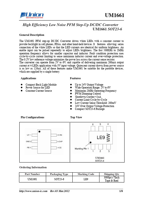
High Efficiency Low Noise PFM Step-Up DC/DC Converter UM1661 SOT23-6General DescriptionThe UM1661 PFM step-up DC/DC Converter drives white LEDs with a constant current to provide backlight in cell phones, PDAs, and other hand-held devices. It features allowing series connection of the white LEDs so that the LED currents are identical for uniform brightness. An enable input can be pulsed repeatedly to adjust LEDs brightness. The fast 500KHz to 2MHz operation frequency allows for smaller capacitor and inductor. Fault condition protection uses cycle-by-cycle current limiting to sense maximum inductor current and over-voltage protection. The 0.2V low reference voltage minimizes the power loss across the current sense resistor.The converter can operate from 2V to 6V , and capable of delivering maximum 200mA output current at 4-LEDs application with 3V input voltage. Quiescent current drawn from power source is as low as 120uA. All of these features make UM1661 be suitable for the portable devices, which are supplied by a single battery.ApplicationsFeaturesz Compact Back Light Module z Power Source for LED z Constant Current Sourcez Up to 24V Output Voltagez Wide Operation Range: 2V to 6Vz Maximum 2MHz Operating Frequency z PWM Dimming Control z Shutdown Current <1uAz Current Limit Cycle-by-Cyclez Low Current Sense Threshold: 200mV z 24V Over Output Voltage Protection zCompact SOT23-6 PackagePin ConfigurationsTop ViewOrdering InformationPart NumberPackaging TypeMarking CodeShipping Qty UM1661 SOT23-6 LE93000pcs/7InchTape & ReelUM1661 SOT23-6Pin DescriptionPin Number Symbol Function1 LXSwitchingPin2 GNDGroundPin3 FB Pin for Feedback Voltage4 CE Chip Enable Pin (Active with “H”)5 OVP Over Voltage Protection6 VIN Power Supply PinAbsolute Maximum RatingsSymbol Parameter ValueUnit V IN Supply Voltage on VIN -0.3 to +8.0 VV CE Voltages on Pin CE -0.3 to V IN +0.3 VI LX LX Pin Output Current 1.6 AV LX LX Pin Voltage 24 VP D Continuous Power Dissipation 250 mWT A Operating Ambient Temperature -40 to +85 °CT J Operating Junction Temperature +125 °CT STG Storage Temperature Range -40 to +150 °CT L Maximum Lead Temperature for Soldering 10seconds+260 °CElectrical Characteristics(V IN= 3.0V, V CE= 3.0V, T A = 25°C, unless otherwise noted)Symbol Parameter TestConditions MinTypMaxUnit V IN Input Voltage Range 2.0 6.0 V V FB FeedbackVoltage 0.1900.200 0.210 VI FB FB Pin Bias Current 10 45 100 nAV FB = 0.3V 93 120I Q QuiescentCurrentV CE = 0V 0.4 1.0μAF OSC_ MAX Maximum SwitchingFrequencyV FB =0V 2 MHzI Limit Switching Current Limit 1.6 A V CESAT SwitchingVCESAT I LX=300mA 260 mV I LX Switching pin Leak Current V LX=5V 0.11 μAV CEH CE Voltage High CE=0V to 3V 1.5 V V CEL CE Voltage Low CE=3V to 0V 0.4 V I CE CE pin Bias Current 18 μAV OVP Over Voltage Protection 24 VFunction Block DiagramTypical Application CircuitL1LED19D1VINLED18LED17LED20Typical Operating Characteristics(V IN = 3.0V, V CE = 3.0V, T A = 25°C, unless otherwise noted)0102030405060708090100Efficiency vs. Output CurrentE f f i c i e n c y (%)Output Current(mA)102030405060708090100Efficiency vs. Output CurrentE f f i c i e n c y (%)Output Current(mA)0102030405060708090100Efficiency vs. Output CurrentE f f i c i e n c y (%)Output Current(mA)CE Pin Bias Current vs. CE VoltageC E P i n B i a s C u r r e n t (u A )CE Pin Voltage(V)C E P i n C u r r e n t (u A )Temperature(oC)0.00.10.20.30.40.50.60.70.80.91.0Q u i e s c e n t C u r r e n t (u A )Supply Voltage(V)Typical Operating Characteristics (Continued)(V IN = 3.0V, V CE = 3.0V, T A = 25°C, unless otherwise noted)0102030405060708090100Q u i e s c e n t C u r r e n t (u A )Supply Voltage(V) 2.0 2.5 3.0 3.5 4.0 4.5 5.0 5.5 6.00.120.140.160.180.200.22FB Pin Voltage vs. Supply VoltageF B P i n V o l t a g e (V )Supply Voltage(V)F B P i n Vo l t a g e (V )Temperature(o C)0.00.51.01.52.02.53.03.54.0S w i t c h F r e qu e n c y (M H Z )Supply Voltage(V)S w i t c h F r e q u e n c y (M H Z )Temperature(oC)Maximum Output Current vs. Output Voltage M a x i m u m O u t p u t C u r r e n t (m A )Output Voltage (V)Application InformationLED Current ControlThe UM1661 regulates the LED current by setting the current sense resistor (R1) connecting to feedback and ground. The UM1661 feedback voltage (V FB) is 0.20V. The LED current (I LED) can be set by a resistor R1. I LED = 0.20/R1. In order to have an accurate LED current, a precision resistor is preferred (1% is recommended).PWM Dimming ControlWhen adding the PWM signal to CE pin, the UM1661 is turned on or off by the PWM signal, so the LEDs operate at either zero or full current. The average LED current increase proportionally with the duty cycle of the PWM signal. The magnitude of the PWM signal should be higher than the maximum enable voltage of EN pin, in order to let the dimming control perform correctly. The recommended frequency range of the PWM signal is from 100Hz to 100 kHz.Inductor SelectionThe recommended value of inductor is 2.2μH to 10μH. Small size and better efficiency are the major concerns for portable device, such as UM1661 used for mobile phone. The inductor should have low core loss at 2MHz and low DCR for better efficiency. To avoid inductor saturation current rating should be considered.Capacitor SelectionInput and output ceramic capacitors of 4.7μF are recommended for UM1661 applications. For better voltage filtering, ceramic capacitors with low ESR are recommended. X5R and X7R types are suitable because of their wider voltage and temperature ranges.Diode SelectionSchottky diode is a good choice for UM1661 because of its low forward voltage drop and fast reverses recovery. Using Schottky diode can get better efficiency. The high speed rectification is also a good characteristic of Schottky diode for high switching frequency. Current rating of the diode must meet the root mean square of the peak current and output average current multiplication as following:I D(RMS)≈ (I OUT×I PEAK )1/2The diode’s reverse breakdown voltage should be larger than the output voltage. SS0520 is recommended Schottky diode for rectifier.Layout Guidez A full GND plane without gap break.z Minimized LX node copper area to reduce EMI.z Minimized FB node copper area and keep far away from noise sources.Package InformationUM1661: SOT23-6Outline DrawingDIMENSIONSMILLIMETERS INCHESSymbolMin Max Min MaxA 1.050 1.250 0.0410.049A1 0.0000.100 0.000 0.004A2 1.050 1.150 0.041 0.045b 0.3000.500 0.012 0.020c 0.1000.200 0.004 0.008D 2.820 3.020 0.111 0.119E 1.500 1.700 0.059 0.067E1 2.650 2.950 0.104 0.116e 0.950REF 0.037REF e1 1.800 2.000 0.071 0.079L 0.600REF 0.023REF L1 0.3000.600 0.012 0.024θ 0° 8° 0° 8°Land PatternNOTES:1. Compound dimension:2.92×1.60; 2. Unit: mm;3. General tolerance ±0.05mm unless otherwise specified;4. The layout is just for reference.Tape and Reel OrientationIMPORTANT NOTICEThe information in this document has been carefully reviewed and is believed to be accurate. Nonetheless, this document is subject to change without notice. Union assumes no responsibility for any inaccuracies that may be contained in this document, and makes no commitment to update or to keep current the contained information, or to notify a person or organization of any update. Union reserves the right to make changes, at any time, in order to improve reliability, function or design and to attempt to supply the best product possible.Union Semiconductor, IncAdd: Lane 647, 3 Building, 2 F, Song Tao Road, Shanghai 201203Tel*************Fax*************Website: This datasheet has been downloaded from:Free DownloadDaily Updated Database100% Free Datasheet Search Site100% Free IC Replacement Search SiteConvenient Electronic DictionaryFast Search SystemAll Datasheets Cannot Be Modified Without Permission。
MAX DC-DC变换集成电路的特点及其应用
MAX DC-DC变换集成电路的特点及其应用
刘红民
【期刊名称】《鞍山钢铁学院学报》
【年(卷),期】1997(20)2
【摘要】简要介绍了美国MAXIM公司部分DC-DC变换集成电路的主要特性和典型应用电路,并给出了参数设计方法。
【总页数】5页(P24-28)
【关键词】DC-DC变换;集成电路;电路
【作者】刘红民
【作者单位】
【正文语种】中文
【中图分类】TN43
【相关文献】
1.DC-DC变换器MAX 877/878/879 [J], 郑晓红
2.双输出DC—DC变换集成电路MAX743 [J], 方佩敏
3.DC-DC变换器MAX752 [J], 方佩敏
4.简单实用的DC-DC变换器MAX 630 [J], 冯乙引;王珂
5.DC-DC 变换器用控制 IC-MAX1710 [J], 岳云;万澄
因版权原因,仅展示原文概要,查看原文内容请购买。
Maxim MAX77831 18W高效降压-升压转换器解决方案

Maxim公司的MAX77831是2.5V-16V输入18W输出的高效降压-升压转换器.当采用内部反馈电阻时器件的默认输出电压是5V.当采用外接反馈电阻时,也可以配置成3V和15V间任何电压,输出电压通过I2C接口动态进行调整,而器件仅工作在增强PWM(FPWM)模式.SEL引脚允许单个外接电阻进行四个不同的I2C接口从寻址,四个不同开关电流设限阈值,一种在外接/内部反馈电阻之间选择.这四种开关电流设限阈值允许使用更小的尺寸和更小的外接元件.采用外接反馈电阻有更宽的输出电压范围和定制化输出电压.输入电压为2.5V到16V,默认开关频率1.8MHz,通过I2C接口可选择1.5MHz和1.2MHz.具有软起动和多种保护特性如欠压锁住(UVLO),过流保护(OCP),过压保护(OVP)以及热关断(THS).2.86mm x 2.06mm 35 WLP封装,主要用在高达16V的非电池供电应用以及带EN控制的高达16V的电池供电应用.本文介绍了MAX77831主要优势和特性,简化框图,功能框图,典型应用电路图以及评估板MAX77831 EVK主要特性和指标,电路图表,材料清单和PCB设计图.The MAX77831 is a high-efficiency, high-performancebuck-boostconverter targeted for systems requiring wideinput voltage range (2.5V to 16V). It can supply 18W ofcontinuous output power (for example, up to 2A at 9V (VIN≥ 4V)).The IC is available in 5V default output voltage when usinginternalfeedback resistors. The IC can also be configuredto any default outputvoltages between 3V and 15Vwhen using external feedback resistors. The output voltageis adjustable dynamically through the I2C serial interface.TheIC only operates in forced-PWM (FPWM) mode.The SEL pin allows a single external resistor to programfour different I2C interface slave addresses, four differentswitching-current limitthresholds, and selection betweenexternal/internal feedback resistors. The different switching-current limit thresholds allow the use of lowerprofileand smaller external components that are optimized for aparticular application. The use of external feedback resistorsallows for a wider output voltage range and customizableoutput voltages at startup.An optional I2C serial interface allows dynamically controllingtheoutput voltage, slew rate of the output voltagechange, switching-current limit threshold, and switchingfrequency. The I2C-programmed settingshave priorityover the RSEL decoded settings.The MAX77831 is available in a 2.86mm x 2.06mm35-bump wafer level package (WLP).MAX77831主要优势和特性:● Wide Input Voltage Range: 2.5V to 16V● Default Output Voltage• 5V with Internal Feedback Resistors• 3V to 15V with External Feedback Resistors● Default 1.8MHz Switching Frequency• 1.5MHz and 1.2MHz Selectable through the I2CInterfaceMaxim MAX77831 18W高效降压-升压转换器解决方案● Forced-PWM (FPWM) Mode Operation Only ● I2C-Programmable Output Voltage After Startup • 4.5V to 15V (Internal Feedback Resistors)• 3V to 15V (External Feedback Resistors● 18W of Continuous Output Power (VIN ≥ 4V, VOUT ≥5V)● RSEL Configuration • I2C Interface Slave Address • Switching Current Limit Threshold • Internal/External Feedback Resistors● I2C Programming • Output Voltage (DVS)• Slew Rate of Output Voltage Change • Switching Current Limit Threshold • Switching Frequency• Power-OK (POK) Status and Fault Interrupt Masks • Internal Compensation ● Soft-Start● Output Active Discharge● Open-Drain Power-OK (POK) Monitor/Fault ConditionInterrupt ● Protection Features• Undervoltage Lockout (UVLO)• Overcurrent Protection (OCP)• Overvoltage Protection (OVP)• Thermal Shutdown (THS)● High Density Interconnect (HDI) PCB Not Required ● Available in 2.86mm x 2.06mm 35 WLPMAX77831应用:● Non-Battery Powered Applications up to 16V Input● Battery Powered Applications up to 16V Input with ENControl图1.MAX77831简化框图。
