MQF21.4-1200-13中文资料
SCPQ-90中文资料
JYPQ
LRPQ-J
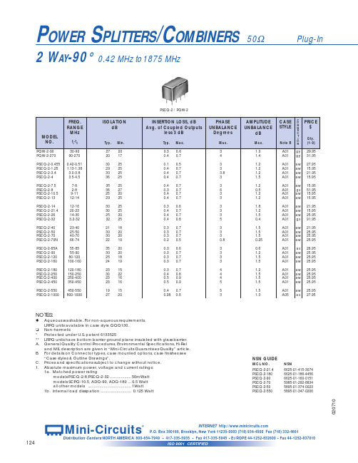
INSERTION LOSS, dB Avg. of Coupled Outputs less 3 dB
PHASE UNBALANCE
Degrees
Typ. Max.
0.2
0.7
0.2 0.7 0.2 0.7
0.45 1.4 0.5 1.0 0.2 0.5 0.2 0.6 0.5 1.1
21 18 30 20 30 20 22 19
35 20 30 20 25 18 24 19
23 15 30 22 23 16 23 16
19 15 27 20
PSCQ-2 / PQW-2
INSERTION LOSS, dB Avg. of Coupled Outputs
less 3 dB
Typ. Max.
1a. Matched power rating models PSCQ-2-8,PSCQ-2-32 ................... 50mWatt models SCPQ-10.5, ADQ-90, ADQ-180 ... 0.5 Watt all other models ...................................... 1Watt
6
7
3
6
NOT USED
—
—
—
—
—
gx 1 2 5 3,4,7,8 — — —
gy 1 2(0°) 6(90°) 3,4,7,8
5 —
hm
ja
9
1
2(0°)
8
6(-90°)
14
1,3,4,5,7,8 2,3,4,5,6,9
10,11,12,14 10,11,12,13
SIEMENS QFM21 风管式传感器 说明书
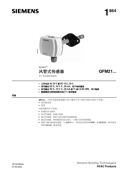
1864Symaro™风管式传感器QFM21...用于相对湿度和温度1864P 01• 工作电压AC 24 V 或 DC 13.5...35 V• 信号输出DC 0...10 V/ 4…20 mA ,用于相对湿度• 信号输出 DC 0...10 V/ 4…20 mA 或T1 或 LG-Ni 1000,用于温度 •测量精度为舒适范围内的±3 % 相对湿度用途QFM21… 风管式温度传感器专用于通风与空气调节设备中的以下用途:• 相对湿度和 • 温度该传感器有以下用途: • 控制送风与排风• 参考传感器,如露点转换• 限定传感器,例如与蒸汽湿度传感器相连• 限定传感器,例如测量值显示或与一个楼宇自控系统相连• 焓值与绝对湿度传感器,与AQF61.1 (参考技术资料N1899)或SEZ222(参考技术资料N5146)配套使用CE1N1864en Siemens Building Technologies型号一览参考型号温度 测量范围温度 信号输出湿度 测量范围湿度 信号输出工作电压QFM2100 None None 0...100 % DC 0...10 V AC 24 V or DC 13.5…35 V QFM2101 None None0...100 % 4…20 mA DC 13,5…35 VQFM2120 −35...+50 °C LG-Ni 1000 0...100 % DC 0...10 V AC 24 V or DC 13.5…35 V QFM2140 −35...+50 °C T1 (PTC) 0...100 % DC 0...10 V AC 24 V or DC 13.5…35 V QFM2160 0...50 °C or −35...+35 °C DC 0...10 V 0...100 % DC 0...10 V AC 24 V or DC 13.5…35 V QFM21710...50 °C or −35...+35 °C4…20 mA0...100 %4…20 mADC 13.5…35 V订货和交货订货时,请注明产品名称和参考型号,例如: 风管式温度传感器QFM2120安装法兰和电线接入密封管M16与传感器一同供货。
各种球磨机的详细资料配比

MQG2400×3000 干湿 20 15.5 ≤25 0.043-0.8 8-15 YR4004-8 250 9128×4956×4018 65.88
内衬:石衬 δ=140 橡胶衬 δ=60
机重(不含衬):19000kg
型号:QM3500×6000P
筒体容积:57.7 m3
工作转速:12.5r/min
辅助转速:1.5r/min
主电机型号、功率:Y315L2-6 110kW
辅助电机型号、功率:Y200L-6 18.5kW
MQG1500×3000 干湿 28.8 8.0 ≤25 0.074-0.4 2.5-8.0 JR125-8 95 7604×3135×2658 17
MQG1500×3500 干湿 28.8 8.5 ≤25 0.074-0.4 3.0-8.5 YR280M-8 75 8104×3135×2658 19.5
MQG1200×1200 干湿 35 2.4 ≤25 0.074-0.8 2.0-3.0 Y250M-8 30 5520×2800×2550 11.4
MQG1200×1600 干湿 32 2.5 ≤25 0.074-0.8 2.0-3.6 Y225S-8 18.5 4099×2155×1855 8.8
MQG1830×5500 干湿 24.5 14.0 ≤25 0.043-0.8 6.0-10 JR136-8 180 10820×4685×3750 34.5
MQG1830×6400 干湿 24.5 16.0 ≤25 0.043-0.8 8.0-10.0 JR137-8 210 11720×4685×3750 36
MQ系列传感器规格

灵敏度调整: MQ131型气敏器件对不同种类,不同浓度的气体有不同的电阻值。 因此,在使用此类型气敏元件时,
灵敏度的调整是很重要的。 我们建议您用50ppbO3校准传感器。 当精确测量时,报警点的设定应考虑温湿度的影响。 附图:元件对臭氧及干扰气体的灵敏度比较。
元件底座开有圆孔如使元件内部气体与空气交换良好如用风机强吸元件则有较高的灵敏度和较快的响应符号参数名称技术条件备注vc回路电压5v01加热电压5v01负载电阻可调加热电阻353室温加热功耗小于850毫瓦符号参数名称技术条件备注tao使用温度2050tas储存温度2070rh相对湿度小于95rh符号参数名称技术条件备注rs敏感体电阻200k1000k50ppbo探测范围
恢复速度。测量电路如图2。
E. 灵敏度特性曲线
MQ131
图3给出了MQ131型气敏元 件的灵敏度特性。
其中: 温度:20℃、 相对湿度:65% 、 氧气浓度:21% RL=100kΩ Rs:元件在不同气体,不同浓度下 的电阻值。 R0: 元件在洁净空气中的电阻值
图 3 MQ131灵敏度特性曲线
图4给出了MQ131型气敏元件的温湿度 特性
V V V
10 8 6 4 2 0 0
臭氧灵敏度 0.05
10 8 6 4 2 0 0.1ppm 0
10 酒精
8
6
H2
4
烟
2
CH4
0
200
400 ppm
0
2000
4000 ppm
A.
Vc VH RL RH PH
B.
Tao Tas
Vaisala GMW90 二氧化碳和温度传感器说明书

GMW90 CO2 and Temperature Transmitter - BACnet/Modbus1234567891011Vaisala Carbocap ® CO2 and Temperature Transmitter GMW905000Price5Display and colour Standard White (RAL9003, solid cover)0Standard White (RAL9003, display cover)1Black (RAL9005, solid cover)2Black (RAL9005, display cover)3No logo, standard White (RAL9003, solid cover)8No logo, standard White (RAL9003, display cover)9Indicator cover (RAL9003, display and CO2 indicators)A6Units MetricA Non metricB 7Display configuration Default (T, CO2)A CO2CO2C8Elevation setting Standard (sea level)0Custom Define m (ft)X 9CO2 indicator levels None0Standard (800,1200 ppm)1Custom Define YellowRed ppmX 10Trimmers With adjustement trimmerA No adjustement trimmerB11Quick reference guide No manual0Multilingual for digital devices 2Accessories:TM10SP Temperature measurement module GM10SP CO2 measuremnt module219980Connection cable for HM70 hand-held meter 219690USB cable for PC connectionSelections in bold are included in the prices of the basic versions Selections in italic are available at an extra costGMW9050001A A 00A 2GMW90 CO2 and Temperature Transmitter - Current output1234567891011Vaisala Carbocap ® CO2 and Temperature TransmitterGMW904Price2Output signal 4...20mA 3-wire 40...20mA 3-wire 53Output parameter for CH1CO20...2000 ppm L CO20...5000 ppm M CO2, free scaleDefine Low High ppm N T, free scaleDefine Low High °C (°F)T 4Output parameter for CH2T -5...+55 °C (+23...+131 °F)E T 0...+60 °C (+32...+140 °F)F CO2, free scaleDefine Low High ppm N T, free scaleDefine Low High °C (°F)T 5Display and colour Standard White (RAL9003, solid cover)0Standard White (RAL9003, display cover)1Black (RAL9005, solid cover)2Black (RAL9005, display cover)3No logo, standard White (RAL9003, solid cover)8No logo, standard White (RAL9003, display cover)9Indicator cover (RAL9003, display and CO2 indicators)A6Units Metric ANon metric B7Display configuration Default (T, CO2)ACO2C8Elevation setting Standard (sea level)0Custom Define m (ft)X9CO2 indicator levels None 0Standard(800,1200 ppm)1Custom Define Yellow Red ppmX 10Trimmers With adjustement trimmer ANo adjustement trimmer B11Quick reference guide No manual0Multilingual for analog devices 1Accessories:TM10SP Temperature measurement module GM10SP CO2 measuremnt module219980Connection cable for HM70 hand-held meter 219690USB cable for PC connectionSelections in bold are included in the prices of the basic versions Selections in italic are available at an extra costGMW9044L E 1A A 00A 1GMW90 CO2 and Temperature Transmitter - Voltage output1234567891011Vaisala Carbocap ® CO2 and Temperature TransmitterGMW903Price2Output signal 0...10 V 3-wire 20...5 V 3-wire 33Output parameter for CH1CO20...2000 ppm L CO20...5000 ppm M CO2, free scaleDefine Low High ppm N T, free scaleDefine Low High °C (°F)T 4Output parameter for CH2T -5...+55 °C (+23...+131 °F)E T 0...+60 °C (+32...+140 °F)F CO2, free scaleDefine Low High ppm N T, free scaleDefine Low High °C (°F)T 5Display and colour Standard White (RAL9003, solid cover)0Standard White (RAL9003, display cover)1Black (RAL9005, solid cover)2Black (RAL9005, display cover)3No logo, standard White (RAL9003, solid cover)8No logo, standard White (RAL9003, display cover)9Indicator cover (RAL9003, display and CO2 indicators)A6Units Metric ANon metric B7Display configuration Default (T, CO2)ACO2C8Elevation setting Standard (sea level)0Custom Define m (ft)X9CO2 indicator levels None 0Standard(800,1200 ppm)1Custom Define Yellow Red ppmX 10Trimmers With adjustement trimmer ANo adjustement trimmer B11Quick reference guide No manual0Multilingual for analog devices 1Accessories:TM10SPGM10SP Temperature measurement module219980Connection cable for HM70 hand-held meter 219690USB cable for PC connectionSelections in bold are included in the prices of the basic versions Selections in italic are available at an extra costGMW9032L E 1A A 00A 1。
EN中文版
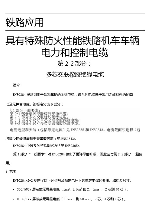
铁路应用具有特殊防火性能铁路机车车辆电力和控制电缆第2-2部分:多芯交联橡胶绝缘电缆简介EN50264涉及到用于铁路车辆的系列电缆,该系列电缆属于采用无卤材料的护套以及无护套电缆。
该标准分为5部分:括减少环境温度和安装类型因素)见EN50343oEN50264中涉及的特殊测试方法见EN50305o第1部分“一般要求”对EN50264做出了更详尽的介绍,因此应与第2-2部分一起使用。
1.范围EN50264-2-2规定了对下列型号及额定电压下的单芯电缆的要求、结构及尺寸。
•300/500V屏蔽或无屏蔽电缆(lmm\ 1.5mm2和2. 5mm:, 2芯到40芯);•0. 6/lkV屏蔽或无屏蔽电缆(1.5mm:到50mm,, 2芯、3芯和4芯)。
注:并非每个类型都规定J'导线尺寸或线芯数目所有的电缆采用5类镀锡铜线,符合EN60228的规定,且为无卤绝缘和无卤护套。
这些电缆用于铁路机车固定布线,或者操作时会碰到极限挠度的布线。
要求连续导线温度不超过90°C,在5秒内,短路条件下最大温度为200°C。
发生火灾时,电缆在最大允许火焰传播(火焰蔓延),最大允许烟雾及有毒气体释放等方面具有特殊的性能。
EX50264-2-2应与第1部分“一般要求” 一起使用。
2.引用标准以下引用的文件对于实施本文件是必不可少的。
凡注日期的引用文件,最新版不适用于本标准。
不注日期的引用文件,其最新版(包括任何修订)适用于本标准。
EN10002-1金属材料一拉伸测试一室温条件下试验方法EN50264-1铁路应用一具有特殊防火性能铁路机车车辆动力和控制电缆第1部分:一般要求EN50266-2-4电缆在火焰条件下的通用试验方法一垂直安装的成束电线或电缆的垂直火焰蔓延试验第2-4部分:试验步骤一C类EN50266-2-5电缆在火焰条件下的通用试验方法一垂直安装的成束电线或电缆的垂直火焰蔓延试验第2-5部分:试验步骤一小电缆一D 类EN50305:2002铁路应用-具有特殊防火性能铁路机车车辆电缆-测试方法EX50334电缆芯线识别用符号标记EN60228 电缆的导体(IEC60228)EN60332-1-2电缆和光缆在火焰条件下的试验方法第1-2部分:单根绝缘电线电缆垂直火焰蔓延试验一lkW预混合火焰(IEC660332-1-2) EN608U-l-l:1995电缆和光缆绝缘和护套材料的一通用试验方法第1~1部分:一般应用一厚度和外形尺寸测量一机械性能试验(IEC60811-l-l:1993)EN60811-1-2:1995电缆绝缘和护套材料的一通用试验方法第1-2部分:一般应用一热老化试验 (IEC60811-l-2:1985+Al : 1989+corr.Mayl986)EN60811-1-3:1995电缆和光缆绝缘和护套材料的一通用试验方法第1-3部分:一般应用一密度测定方法一吸水试验一回缩试验(IEC60811-1-3:1993)EN60811-1-4:1995电缆和光缆绝缘和护套材料的一通用试验方法第1-4部分:一般应用一低温试验(IEC60811-1-4:1985+A11993+corr.May1986 ) EN60811-2-l:1998电缆和光缆绝缘和护套材料的一通用试验方法第2-1部分:一般应用一橡胶混合物测试方法一耐臭氧试验、热延伸试验和浸矿物油试验(IEC60811-2-1:1998)EN61034-2电缆在特定条件下燃烧的烟密度测定第2部分:试验步骤和要求(IEC61034-2)HD308电缆与软线的芯线标记3.定义EN50264-1的定义适用于木标准。
满堂脚手架搭设施工方案
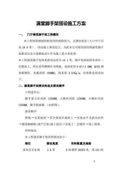
满堂脚手架搭设施工方案一、门厅满堂脚手架工程概况本工程屋面钢筋砼框架因结构跨度大, 支撑高度高(入口中厅层高16.6米), 因而施工难度较大。
为此本公司将屋面结构满堂脚手架搭设以及大梁模板设计作为施工重点来处理。
本工程满堂脚手架体系搭设高度为16.1米, 脚手架基础因坐落在二层楼面上, 所以采用槽钢作为垫板。
选材采用φ48×3.5MM, Q235钢普碳钢管, 其截面积489MM2, 线重量 3.84Kg/m, 具体搭设要求如下。
二、满堂脚手架搭设构造及搭设顺序◇构造单元:脚手架立杆间距1200MM, 大横杆间距1200MM, 小横杆间距1500MM, 脚手板满铺。
(如附图)。
搭设顺序:弹线→安放底座→首步架装在底座上→安装水平及斜向拉杆→铺设脚踏板(或平行架)插上驳芯→安装上一层钢管→装上锁臂。
用料情况:本工程满堂脚手架用料情况如下:部位搭设高度用料数量及规格基本层C-G轴 3.6米φ48钢管39385米, 重151吨入口门厅B-C轴 16.6米φ48钢管3096.4, 重11.9吨入口门厅A-B轴 17.4米φ48钢管1662.7米, 重6.35吨三、满堂脚手架搭设方案验算本方案以入口门厅16.6米高满堂脚手架为例, 验算各搭设参数。
◇荷载计算:立杆每米高自重: 38.4N脚手板自重: 250N/M2施工荷载: 2650N/M2扣件重量: 9.8N/个◇立杆轴心荷载计算:脚手架立杆自由高度按2.5M考虑。
其计算简图如附图所示。
N=H0P n+ab2(0.5n1q1+ηn2q2)式中:P n——每米架高脚手架总重量。
按115N/M考虑。
H0——立杆总高。
取17M。
a——立杆间距。
取1.5M。
b2——脚手架宽度。
取1.0M计算单元。
n1——满铺脚手板层数。
取4。
q1——脚手板自重。
取250N/M2n2——有效作业层数。
取2层。
q2——脚手板上施工荷载。
取5000N/M2η——脚手架内外立杆分配系数。
Hurricane 1200 用户手册说明书

User ManualT ABLE OF C ONTENTS1. Before You Begin (3)What Is Included (3)Unpacking Instructions (3)Claims (3)Text Conventions (3)Symbols (3)Disclaimer (3)Product at a Glance (4)Safety Notes (4)2. Introduction (5)Overview (5)Dimensions (6)3. Setup (7)AC Power (7)Fuse Replacement (7)Mounting (8)Orientation (8)Rigging (8)4. Operation (9)Remote or Manual Operation (9)Wired Timer Controller (FC-T) Setup (9)Wired Timer Controller (FC-T) Operation (9)Optional Wired Manual Remote Control (FC-M) (10)Optional Wireless Remote (FC-W) (10)Fluid Tank Indicator Lights (10)5. Technical Information (11)Fogger Maintenance (11)Storage (11)6. General Troubleshooting (12)7. Technical Specifications (13)Returns (14)Contact Us (15)Page 2 of 15 Hurricane™ 1200 User Manual Rev. 21.B EFORE Y OU B EGINWhat Is Included ·Hurricane™ 1200·FC-T Timed Remote Control·Hanging Bracket with Mounting Hardware·Warranty Card·Quick Reference GuideUnpacking Instructions Carefully unpack the product immediately and check the container to make sure all the parts are in the package and are in good condition.Claims If the box or the contents (the product and included accessories) appear damaged from shipping, or show signs of mishandling, notify the carrier immediately, not Chauvet.Failure to report damage to the carrier immediately may invalidate your claim. Inaddition, keep the box and contents for inspection.For other issues, such as missing components or parts, damage not related to shipping,or concealed damage, file a claim with Chauvet within 7 days of delivery.Text ConventionsConvention Meaning1—512 A range of values50/60 A set of valuesSettings A menu optionMenu > Settings A sequence of menu options <Enter>A buttonDisclaimer The information and specifications contained in this User Manual are subject to change without notice. Chauvet assumes no responsibility or liability for any errors or omissions,and reserves the right to revise or recreate this manual at any time. Download the latestversion from .© Copyright 2015 Chauvet. All rights reserved.Electronically published by Chauvet in the United States of America.Author Date Editor DateR. Isenstadt 07/14/2015 M. Trouard 07/14/2015Hurricane TM 1200 User Manual Rev. 2 Page 3 of 15Page 4 of 15 Hurricane™ 1200 User Manual Rev. 2Safety Notes These notes include important information about the mounting, usage, and maintenanceof this product; read before using the product.·Always connect the product to a grounded circuit to avoid the risk of electrocution.·Always disconnect the product from the power source before cleaning or replacing the fuse.· Make sure the power cord is not crimped or damaged.· Never disconnect the product from power by pulling or tugging on the cord. · If mounting the product overhead, always secure to a fastening device using a safety cable.· Make sure there are no flammable materials close to the product when operating. · Do not touch the product’s housing when operating because it may be very hot. ·Do not mount the product on a flammable surface (linoleum, carpet, wood, paper, carton, plastic, etc.).· The product’s nozzle is very hot during operation and it remains hot for a long time after operation has stopped.· The fog exits the nozzle at a very high temperature. Keep a minimum distance of 6.5 ft (2 m) from the nozzle to the nearest object. · Do not use the product as a space heater.· Do not drink or come in contact with the fog fluid. If you do, call your local emergency service (911 in the US) for help.·Do not add perfume, alcohol, gasoline, or any other flammables to the fog fluid.· Always make sure that the voltage of the outlet to which you are connecting the product is within the range stated on the decal or rear panel of the product.· The product is for indoor use only! (IP20) To prevent risk of fire or shock, do not expose the product to rain or moisture.· Always install the product in a location with adequate ventilation, at least 20 in (50 cm) from adjacent surfaces.· Be sure that no ventilation slots on the product’s housing are blocked. · Never connect the product to a dimmer or rheostat.· Make sure to replace the fuse with another of the same type and rating.·Never carry the product from the power cord or any moving part. Always use the hanging/mounting bracket.·The maximum ambient temperature (Ta) is 104 °F (40 °C). Do not operate the product at higher temperatures.· In the event of a serious operating problem, stop using the product immediately. · Never try to repair the product. Repairs carried out by unskilled people can lead to damage or malfunction. Contact the nearest authorized technical assistance center. · This product is not intended for permanent installation. · Use only CHAUVET® water-based fog fluid.· Drain the tank before transporting or storing the product.·To eliminate unnecessary wear and improve its lifespan, during periods of non-use completely disconnect the product from power via breaker or by unplugging it.Keep this User Manual for future use. If you sell the product to another user, be sure to give this document to the next owner.FCQ (Fog Cleaner Quart) was specifically developed by Chauvet to clean your Hurricane™ 1200. Make sure you use FCQ regularly, no longer than 90 days between cleanings, to increase the life of your fogger.Hurricane TM 1200 User Manual Rev. 2Page 5 of 152. I NTRODUCTIONOverviewBack Panel ViewFuse HolderFog FluidPage 6 of 15 Hurricane™ 1200 User Manual Rev. 2Dimensions3.S ETUPAC Power This Hurricane TM 1200 has a fixed voltage power supply and it can work with an input voltage of either 120 VAC, 60 Hz or 230 VAC, 50 Hz, depending on the specific model.To determine the product’s power requirements (circuit breaker, power outlet, andwiring), use the current value listed on the label affixed to the product’s back panel, orrefer to the product’s specifications chart. The listed current rating indicates theproduct’s average current draw under normal conditions.·Always connect the product to a protected circuit (circuit breaker or fuse).Make sure the product has an appropriate electrical ground to avoid the riskof electrocution or fire.·To eliminate unnecessary wear and improve its lifespan, during periods ofnon-use completely disconnect the product from power via breaker or byunplugging it.Never connect the product to a rheostat (variable resistor) or dimmer circuit, evenif the rheostat or dimmer channel serves only as a 0 to 100% switch.Fuse Replacement 1. Disconnect the product from power.2. Twist the fuse holder cap counterclockwise to loosen the fuse holder and pullstraight out.3. Remove the blown fuse.4. Replace with a fuse of the same type and rating.5. Screw the fuse holder cap back in place and reconnect power. ·Disconnect the product from power before replacing the fuse. ·Always replace a blown fuse with another of the same type and rating.Hurricane TM 1200 User Manual Rev. 2 Page 7 of 15Page 8 of 15 Hurricane™ 1200 User Manual Rev. 2MountingBefore mounting the product, read and follow the safety recommendations indicated in the Safety Notes .OrientationThis product may NOT be tilted. This product should be level when on a surface or when mounted.Rigging· Before deciding on a location, always make sure there is easy access to the product for maintenance and fluid replenishment.· Make sure that the structure or surface onto which you are mounting the product can support the product’s weight (see the Technical Specifications ).· When mounting the product overhead, always use a safety cable. Mount the product securely to a rigging point, such as an elevated platform or a truss.·When rigging the product onto a truss, you should use a mounting clamp of appropriate weight capacity. The bracket has 13-mm holes, which are appropriate for this purpose.·The rubber feet also serve as floor supports and allow for surface mounting. When mounting the product on the floor, make sure that the product and cables are away from people and vehicles.Mounting DiagramWhile operating the Hurricane™ 1200, make sure there is adequate fog fluid in the machine to prevent pump and heater damage. When the fog fluid level becomeslow, simply add more fog fluid to continue using the Hurricane™ 1200.MountingBracket(works with CH-05 from Chauvet) Mounting Clamp(such as CLP-15 or CLP-15N clamp fromChauvet)Hurricane TM 1200 User Manual Rev. 2Page 9 of 154. O PERATIONRemote or Manual OperationThe Hurricane™ 1200 can be operated manually, or with the included wired timer controller (FC-T).The Manual button is located on the rear of the unit. See the product Overview . Additionally, the product can be operated with the FC-M manual wired remote or the FC-W wireless remote, available separately.Wired Timer Controller (FC-T)SetupThe FC-T wired timer controller allows you to automatically trigger fog output by setting interval and duration times. LED indicator lights display the machine and controller’s current state. Rotary knobs set interval time, output, and duration time, while manual and continuous buttons allow overriding control.1. Plug in the fog machine to power.2. Plug in the wired timer controller to the Manual Remote Connector socket on the back ofthe fog machine. (See the product Overview .)3. Allow the Hurricane™ 1200 three to four minutes to heat up before continuing. (SeeFluid Tank Indicator Lights .)FC-T Wired Timer Controller OverviewWired Timer Controller (FC-T)OperationThe FC-T wired timer controller has three modes of operation: timer, continuous, and manual.Timer Mode To trigger the Hurricane™ 1200 with the timer function, follow the instructions below:1. Set the desired output level with the OUTPUT knob.2. Set the INTERVAL and DURATION knobs to the desired positions.· The INTERVAL knob sets the amount of time in between bursts of fog.· The DURATION knob sets the length of time that the fog machine will runduring the burst.3. Press the <TIMER ON/OFF> latching button. The LED indicator above the buttonwill light up. The timer will now run as set by the INTERVAL , DURATION , and OUTPUT knobs.4. Press the <TIMER ON/OFF> button again to turn off the timer.The <MANUAL> button will override the timer.Continuous Mode To trigger the Hurricane™ 1200 to continuously cycle fog, follow the instructions below:1. Set the desired output level with the OUTPUT knob.2. Press the <CONTINUOUS> latching button. The LED indicator above the button willlight up. The fog machine outputs fog until the <CONTINUOUS> button is pressed again.3. Press the <CONTINUOUS> button again to stop the fog output.In order for Continuous mode to run uninterrupted, without the Hurricane™ 1200 stopping to reheat, set the OUTPUT knob no higher than 11. At Output levels above 11, the fogger will cycle through intermittent bursts of fog during its reheating program. · The duration of Continuous fog output is based on the capacity of the tank. · Fluid consumption will be significantly increased during Continuous mode.Manual Mode To trigger the Hurricane™ 1200 manually, do the following:1. Set the desired output level with the OUTPUT knob.2. Press and hold the <MANUAL> button on the wired timer controller. The LEDindicator above the button will light up. The fog machine will output fog for as long as you hold down the <MANUAL> button.3. Release the <MANUAL> button to stop the fog output.The duration of manual fog at any given Output setting is based on the capability of the fog machine.Uninterrupted ContinuousMode at Output 11Optional Wired Manual Remote Control (FC-M) The optional FC-M wired manual remote control allows the user to start and stop the fog output. It operates the same as the Manual button on the product, with the addition of a READY indicator LED.1. Plug in the fog machine to power.2. Plug in the wired manual remote control to the Manual Remote Connector socket on theback of the fog machine. (See the product Overview.)3. Wait for the READY indicator LED to light up, indicating the Hurricane™ 1200 is heatedenough to produce fog. (Also see Fluid Tank Indicator Lights.)4. Press and hold the <FOG> button on the wired manual remote control.5. Release the <FOG> button to stop the fog output.FC-M Manual RemoteControl Overview·The Hurricane™ 1200 unit may start producing fog intermittently to allow for fluidreheating after a period of continuous fog output. This is a normal occurrence.·The duration of manual fog output is based on the capability of the fog machine.Optional Wireless Remote(FC-W) The optional FC-W wireless remote allows the user to trigger the Hurricane™ 1200 to produce fog from up to 100 ft away. See1. Plug in the fog machine to power.2. Plug the FC-W wireless remote receiver into the Wireless Remote Connector on the backof the Hurricane™ 1200. (See the product Overview.)3. Allow the Hurricane™ 1200 three to four minutes to heat up. (See Fluid Tank IndicatorLights.)4. Press and hold the <1>, <2>, <3>, or <4> button on the wireless remote. (Download theFC-W User Manual from for more information on addressing the FC-W)5. Release the button to stop the fog output.FC-W WirelessRemote OverviewEnsure the FC-W has an unobstructed view of the receiver for maximum performance.Fluid Tank IndicatorLights The Hurricane™ 1200 has indicator LEDs that light up the fluid tank to indicate the status of the product, as follows:·Red - The heater is currently warming up.·Flashing Red - The heater is currently warming up and no fluid is detected.·Blue - The heater is ready to produce fog.·Flashing Blue - The heater is ready to produce fog and no fluid is detected.Page 10 of 15 Hurricane™ 1200 User Manual Rev. 25. T ECHNICAL I NFORMATIONFogger Maintenance Do not allow the fogger to become clogged. After every 40 hours of continuousoperation, use CHAUVET® Fog Cleaner Quart (FCQ) through the system to prevent theaccumulation of particulate matter in the heating element. The recommended cleaning procedure is as follows. 1. Unplug the product from power.2. Empty all fog fluid from the machine.3. Add cleaning solution to the tank.4. Connect the product to power and allow it to warm up.5. Run the unit in a well-ventilated area until the tank is almost empty. Do not allowthe pump to run dry.6. Refill with fogger fluid to continue using the fogger. Run the machine briefly to clearany remaining cleaning solution from the pump and heater.Do Not operate the machine without fluid at any time.Fog Cleaner Quart (FCQ) was specifically developed by Chauvet to clean your Hurricane™ 1200. Make sure you use FCQ regularly, no longer than 90 days between cleanings, to increase the life of your product.StorageBefore storing the fogger, run FCQ through the system as described in the cleaning procedure above; however, only follow steps 1 through 5. Do not refill the tank with fog fluid if storing the fogger. Cleaning the system prior to storage will help prevent any particles from condensing inside the pump or heater while not in use .Test-run your Hurricane™ 1200 on a monthly basis to achieve the best performance.If you still experience problems after trying the solutions presented here, contact Chauvet Technical Support.7.T ECHNICAL S PECIFICATIONSDimensions andWeight11.3 in (286 mm) 9.3 in (235 mm) 8.2 in (209 mm) 6.4 lb (2.9 kg)Note: Dimensions in inches rounded to the nearest decimal digit.PowerModel-specific 120 VAC, 60 Hz or230 VAC, 50 HzFixedConsumption 1,180 W 1,180 WOperating current 10 A 5.2 AFuse F 13 A, 250 V F 7 A, 250 VPower input connector Hard-wired Hard-wiredPower Cord plug Edison (US) Local plugOperation2 min 0.26 gal (1.0 l) 28 ml/minFog Output Output18,000 cfmThermal Maximum External Temp. Cooling System104 °F (40 °C) ConvectionOrderingHurricane 1200 (120 V) 09071018 781462213664Hurricane TM 1200 (230 V)09071020 781462213688R ETURNSIn case you need to get support or return a product:· If you are located in the U.S., contact Chauvet World Headquarters. · If you are located in the UK or Ireland, contact Chauvet Europe Ltd. · If you are located in Mexico, contact Chauvet Mexico.· If you are located in Benelux, contact Chauvet Europe BVBA.· If you are located in any other country, DO NOT contact Chauvet. Instead, contactyour local distributor. See for distributors outside the U.S., UK, Ireland, Mexico, or Benelux.If you are located outside the U.S., UK, Ireland, Mexico, or Benelux, contact your distributor of record and follow their instructions on how to return Chauvet products to them. Visit our website for contact details. Call the corresponding Chauvet Technical Support office and request a ReturnMerchandise Authorization (RMA) number before shipping the product. Be prepared to provide the model number, serial number, and a brief description of the cause for the return.Send the merchandise prepaid, in its original box, and with its original packing and accessories. Chauvet will not issue call tags.Clearly label the package with the RMA number. Chauvet will refuse any product returned without an RMA number.Write the RMA number on a properly affixed label. DO NOT write the RMA number directly on the box.Before sending the product, clearly write the following information on a piece of paper and place it inside the box: · Your name · Your address· Your phone number · RMA number· A brief description of the problemBe sure to pack the product properly. Any shipping damage resulting from inadequate packaging will be your responsibility. FedEx packing or double-boxing are recommended.Chauvet reserves the right to use its own discretion to repair or replace returned product(s).C ONTACT U S WORLD HEADQUARTERS - ChauvetGeneral InformationAddress: 5200 NW 108th AvenueSunrise, FL 33351Voice: (954) 577-4455Fax: (954) 929-5560Toll free: (800) 762-1084 Technical SupportVoice: (954) 577-4455 (Press 4) Fax: (954) 756-8015Email: ************************ World Wide Web UNITED KINGDOM AND IRELAND - Chauvet Europe Ltd.General InformationAddress: Unit 1CBrookhill Road Industrial EstatePinxton, Nottingham, UKNG16 6NTVoice: +44 (0)1773 511115Fax: +44 (0)1773 511110 Technical SupportEmail: ************************** World Wide Web MEXICO - Chauvet MexicoGeneral InformationAddress: Av. Santa Ana 30Parque Industrial LermaLerma, Mexico C.P. 52000 Voice: +52 (728) 285-5000 Technical SupportEmail: ********************.mx World Wide Web .mxCHAUVET EUROPE - Chauvet Europe BVBAGeneral Information Address: Stokstraat 189770 KruishoutemBelgiumVoice: +32 9 388 93 97 Technical SupportEmail: ************************* World Wide Web www.chauvetlighting.euOutside the U.S., United Kingdom, Ireland, Mexico, or Benelux contact your dealer. Follow their instructions to request support or to return a product. Visit our website for contact details.。
GMW14124-2012中文版
汽车环境周期1范围注:在本标准中没有将取代适用的法律和法规。
注:在英语和本国语言之间的冲突时,以英文为准。
1.1目的。
此程序文件各种环境周期以及可以在测试之前或作为一个完整的测试进行老化条件。
本规范不包括用于测试或测试前预处理标准条件。
这些要求既可以在材料规格或在GMW3221找到。
1.2前言。
此程序文件已在有关材料规格的全球商定几个周期。
只有那些周期应选择创建GMW材料规格要求。
根据有关材料规格的周期全球公认的有:循环M,Q,R,S,T,U,V和W对于测试周期用途,见4.1.2。
1.3适用性。
请参阅表1的适用性。
注意:某些在本说明书中的测试周期的,最好用作质量控制测试,并且不意味着以验证势场的性能。
更多详情参见平台的材料工程师。
2参考注:除非另有规定,只有最新批准的标准都适用。
2.1外部标准/规范。
ISO9227VDA621-4152.2 GM标准/规范。
GMW3221GMW14444GMW15288GMW3286GMW147293资源3.1设施。
不适用。
3.2设备。
3.2.1机械对流烤箱能够保持从材料规范所要求的温度,以±3℃的公差。
3.2.2恒温恒湿箱能够保持从材料规格所需湿度的±3%的公差的。
3.2.3盐雾柜组成的雾室,盐溶液贮存器,适当地调节压缩空气的供给,一个或多个雾化喷嘴,试样支架,用于加热腔室和控制的必要手段的规定。
是可选的设置大小和盐雾机柜详细结构得到的条件符合该方法的要求。
合适的设备,在ISO 9227中描述。
3.2.4冷室或冷室与能够维持从材料规范要求的温度在±3℃的公差的端口孔。
3.2.5机架或夹具需要支持从垂直位置15和30度之间的试验样品以这样的方式,以防止试验样品或能够创建电偶的任何金属材料之间的接触。
3.2.6蒸汽高压灭菌能够维持所需的温度在±2℃,并能够承受高于大气压(即,2.5巴绝对)高达1.5巴(150千帕)的压力。
将高压釜必须能够在试验完成放空,以防止水过分起泡在打开腔室。
MQ系列气体传感器通用说明书.

通用说明书工作原理MQ系列气体传感器的敏感材料是活性很高的金属氧化物半导体,最常用的如SnO2。
金属氧化物半导体在空气中被加热到一定温度时,氧原子被吸附在带负电荷的半导体表面,半导体表面的电子会被转移到吸附氧上,氧原子就变成了氧负离子,同时在半导体表面形成一个正的空间电荷层,导致表面势垒升高,从而阻碍电子流动(见图1。
在敏感材料内部,自由电子必须穿过金属氧化物半导体微晶粒的结合部位(晶界才能形成电流。
由氧吸附产生的势垒同样存在于晶界而阻碍电子的自由流动,传感器的电阻即缘于这种势垒。
在工作条件下当传感器遇到还原性气体时,氧负离子因与还原性气体发生氧化还原反应而导致其表面浓度降低,势垒随之降低(图2和图3。
导致传感器的阻值减小。
在给定的工作条件下和适当的气体浓度范围内,传感器的电阻值和还原性气体浓度之间的关系可近似由下面方程表示:其中:Rs:传感器电阻A:常数[C]:气体浓度α:Rs曲线的斜率传感器特性1氧气分压的影响图4所示为大气中氧分压(PO2和MQ气体传感器在清洁空气中阻值之间的典型关系。
2气敏特性根据前述方程,在某一气体浓度范围内(从几十ppm 至几千ppm,在工作条件下,传感器的电阻同气体浓度呈对数线性关系。
如图5所示。
传感器对多种还原气体具有敏感性,对指定气体的相对灵敏度,取决于敏感材料的构成及其工作温度。
图1-晶粒间势垒模型(洁净空气实际上,每个传感器的电阻值和相对灵敏度都不完全相同,图5中描述的敏感特性为传感器在不同气体浓度下的阻值(Rs与待检测气体的一定浓度下的阻值(R0的比值与浓度的对数关系。
3传感器响应特性在工作条件下传感器先被放入还原性气体中,其电阻急剧下降,待其稳定后,再将其置入洁净空气中,传感器的电阻经过很短的时间即恢复到它的初始值。
这个过程中传感器典型的动作如图6所示。
传感器的响应速度和恢复速度与传感器型号、材料种类及所测气体的种类相关。
4初始动作如图7所示,当传感器不通电存放后,再在空气中通电,无论是否存在还原性气体,传感器通电后的最初几秒钟,其阻值都会(Rs急剧下降,然后逐渐达到一个平稳的水平,即为传感器的初始动作。
MPSA13中文资料

500 1000
Figure 8. DC Current Gain
Figure 9. Collector Saturation Region
RθV, TEMPERATURE COEFFICIENTS (mV/°C)
1.6 TJ = 25°C 1.4 V, VOLTAGE (VOLTS) VBE(sat) @ IC/IB = 1000 1.2 VBE(on) @ VCE = 5.0 V 1.0
元器件交易网
MOTOROLA
SEMICONDUCTOR TECHNICAL DATA
Order this document by MPSA13/D
Darlington Transistors
NPN Silicon
COLLECTOR 3
MPSA13 MPSA14 *
*Motorola Preferred Device
BASE 2
EMITTER 1
1 2 3
MAXIMUM RATINGS
Rating Collector – Emitter Voltage Collector – Base Voltage Emitter – Base Voltage Collector Current — Continuous Total Device Dissipation @ TA = 25°C Derate above 25°C Total Device Dissipation @ TC = 25°C Derate above 25°C Operating and Storage Junction Temperature Range Symbol VCES VCBO VEBO IC PD PD TJ, Tstg Value 30 30 10 500 625 5.0 1.5 12 – 55 to +150 Unit Vdc Vdc Vdc mAdc mW mW/°C Watts mW/°C °C
IRS20124S中文资料
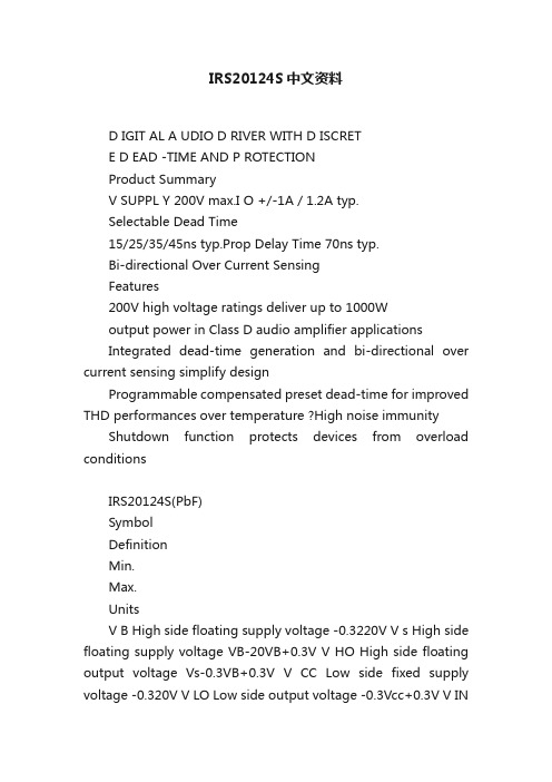
IRS20124S中文资料D IGIT AL A UDIO D RIVER WITH D ISCRETE D EAD -TIME AND P ROTECTIONProduct SummaryV SUPPL Y 200V max.I O +/-1A / 1.2A typ.Selectable Dead Time15/25/35/45ns typ.Prop Delay Time 70ns typ.Bi-directional Over Current SensingFeatures200V high voltage ratings deliver up to 1000Woutput power in Class D audio amplifier applicationsIntegrated dead-time generation and bi-directional over current sensing simplify designProgrammable compensated preset dead-time for improved THD performances over temperature ?High noise immunity Shutdown function protects devices from overload conditionsIRS20124S(PbF)SymbolDefinitionMin.Max.UnitsV B High side floating supply voltage -0.3220V V s High side floating supply voltage VB-20VB+0.3V V HO High side floating output voltage Vs-0.3VB+0.3V V CC Low side fixed supply voltage -0.320V V LO Low side output voltage -0.3Vcc+0.3V V INInput voltage-0.3Vcc+0.3V V OC OC pin input voltage-0.3Vcc+0.3V V OCSET1 OCSET1 pin input voltage -0.3Vcc+0.3V V OCSET2OCSET2 pin input voltage-0.3Vcc+0.3V dVs/dt Allowable Vs voltage slew rate-50V/ns Pd Maximum power dissipation- 1.25W Rth JA Thermal resistance, Junction to ambient -100°C/W T J Junctio n Temperature -150°C T S Storage Temperature-55150°CT LLead temperature (Soldering, 10 seconds)-300°CAbsolute Maximum RatingsAbsolute maximum ratings indicate sustained limits beyond which damage to the device may occur. All voltage parameters are absolute voltages referenced to COM. All currents are defined positive into any lead. The thermal resistance and power dissipation ratings are measured under board mounted and still air conditions.DescriptionThe IRS20124S is a high voltage, high speed power MOSFET driver with internal dead-time and shutdown functions specially designed for Class D audio amplifier applications.The internal dead time generation block provides accurate gate switch timing and enables tight dead-time settings for better THD performances.In order to maximize other audio performance characteristics,all switching times are designed for immunity from external disturbances such as VCC perturbation and incoming switching noise on the DT pin. Logic inputs are compatible with LSTTL output or standard CMOS down to 3.0V without speed degradation. The output drivers feature high current buffers capable of sourcing 1.0A and sinking 1.2A. Internal delays are optimized to achieve minimal dead-time variations. Proprietary HVIC and latch immune CMOS technologies guarantee operation down to Vs= –4V, providing outstanding capabilities of latch and surge immunities with rugged monolithic construction.Recommended Operating ConditionsFor Proper operation, the device should be used within the recommended conditions. The Vs and COM offset ratings are tested with all supplies biased at 15V differential.Symbol Definition Min.Max.Units V B High side floating supply absolute voltage Vs+10Vs+18V V S High side floating supply offset voltage Note 1200VV V HO High side floating output voltage Vs VB V CC Low side fixed supply voltage1018V V LO Low side output voltage0VCC V V IN Logic input voltage0VCC V V OC OC pin input voltage0VCC V V OCSET1OCSET1 pin input voltage0VCC V V OCSET2OCSET2 pin input voltage0VCC V T A Ambient Temperature-40125°CDynamic Electrical CharacteristicsV BIAS (V CC, V BS) = 15V, C L = 1nF and T A = 25°C unless otherwise specified. Figure 2 shows the timing definitions.IRS20124S(PbF)Lead DefinitionsSymbol DescriptionVCC Low side logic Supply voltage VB High side floating supply HO High side outputVS High side floating supply returnINLogic input for high and low side gate driver outputs (HO and LO), in phase with HODT/SD Input for programmable dead-time, referenced to COM. Shutdown LO and HO when tied to COM COM Low side supply returnLO Low side outputOC Over current output (negative logic)OC SET1Input for setting negative over current threshold OC SET2Input for setting positive over current thresholdIRS20124S(PbF)VBHOVSO O C S E T O C S E T VccLOCOM50%50%t off(L)t on(L)90%10%90%10%DT HO-LOt off(H)INHOLOt on(H)DT LO-HO DT/SDHO LOV SDT SD90%Figure 1. Switching Time Waveform Definitions Figure 2. Shutdown Waveform Definitions IRS20124S(PbF)toc filt HIGHVSOCV soct COMCOMtwocVSOCV Soc+tdocCOM COMLOV Soc-15V Vsoc+Vsoc-OCVsoc+Vsoc-COM VSOCFigure 5. OC Waveform DefinitionsFigure 3. OC Input FilterTime Definitions IRS20124S(PbF)IRS20124S(PbF)2.0()2()IRS20124S(PbF)2430()()IRS20124S(PbF)10()10()IRS20124S(PbF)。
早发性与晚发性结直肠癌的发病趋势临床病理特征治疗及预后的对比研究

早发性与晚发性结直肠癌的发病趋势,临床病理特征、治疗及预后的对比研究摘要目的比较早发性结直肠癌(EOCRC)与晚发性结直肠癌(1oCRC)患者的发病趋势、临床病理特征、治疗和预后的差异。
方法病例纳入标准:(1)病理证实的结直肠腺癌,包括遗传性结直肠癌综合征,如1ynCh综合征、家族性腺瘤性息肉病、PeUtZ-JegherS综合征、幼年性息肉病综合征和锯齿状息肉病综合征;(2)在上海长海病理登记系统中有登记信息。
排除邻近器官的恶曲中瘤侵犯结直肠者、远处器官的恶曲中瘤转移至结直肠者、结直肠良性病变者以及复发性CRC患者。
采用回顾性队列研究方法,收集2000年1月1日至2023年12月31日间结直肠癌登记病例资料,采用年均变化率(AAPC)来描述长期变化趋势,比较两组发病趋势、临床、病理、分子和治疗特征以及预后的差异。
结果(1发病趋势共纳入34067例CRC患者其中EoCRC患者6369例,1OCRC患者27698例。
2000—2023年间,EOCRC(AAPC=8.4%)、1OCRC(AAPC=11.6%)和CRC(AAPC=11.0%)病例数均显著增加。
在EOCRC患者中,40-49岁组病例数最多(AAPC=83%),30~39岁组增长最快(AAPC=9.0%),<30岁组的AAPC为7.2%;男性和女性EOCRC患者的AAPC分别为8.8%⅛7.8%;右半结肠癌、左半结肠癌和直肠癌患者的AAPC分别为8.7%、8.9%和7.9%0(2)人口学特征与1OCRC组相比,EOCRC组中男性更少[58.4%(3717/6369券匕63.2%(17497/27698)1=50.785,P<0.001],直肠癌[56.1%(3575/6369)比52.6%(14561/27698),χ^=69.584,P<0.001]和结直肠多原发癌[2.1%(134/6369)比1.2%(343/27698),χ^=27.479f PHOO1]更多,曲半结肠癌[26.7%(1698/6369)比28.4%(7861/27698),χ2=7,511,P=0.006]和右半结肠癌[15.1%(962/6369)比17.8%(4933/27698),χ2=26.300,Ao.001]更少,差异均有统计学意义。
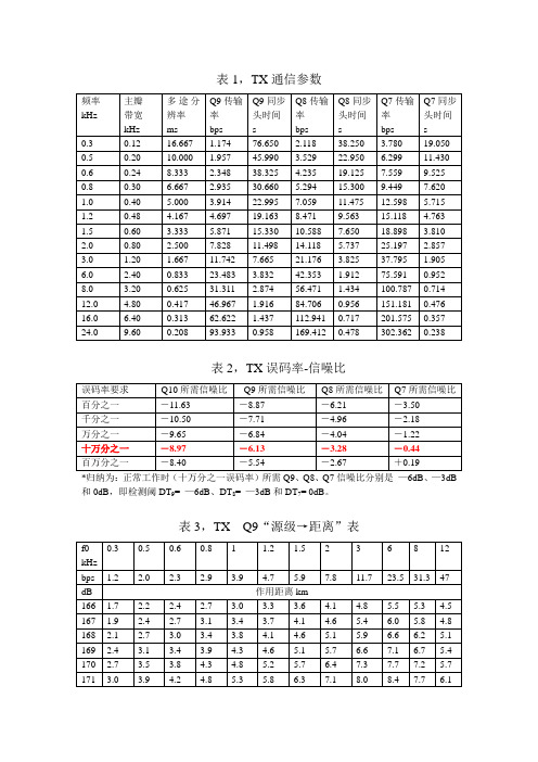
水声遥控通信参数实用计算表mq
0.48
4.167
4.697
19.163
8.471
9.563
15.118
4.763
1.5
0.60
3.333
5.871
15.330
10.588
7.650
18.898
3.810
2.0
0.80
2.500
7.828
11.498
14.118
5.737
25.197
2.857
3.0
1.20
1.667
11.742
154.9
144.2
132.4
118.1
96.5
54.2
38.9
22.9
211
235.2
215.7
202.3
179.6
163.2
151.4
138.4
123.0
100.0
55.7
39.9
23.4
212
257.3
231.5
215.7
189.9
171.8
158.7
144.6
128.0
103.6
57.3
40.9
7.665
21.176
3.825
37.795
1.905
6.0
2.40
0.833
23.483
3.832
42.353
1.912
75.591
0.952
8.0
3.20
0.625
31.311
2.874
56.471
1.434
100.787
0.714
12.0
4.80
L24YK的详细中文资料数据免费下载
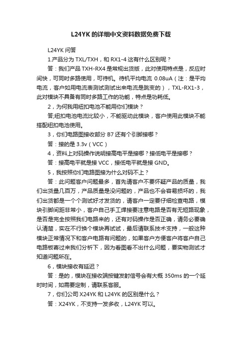
L24YK的详细中文资料数据免费下载L24YK问答1.产品分为TXL/TXH,和RX1-4这有什么区别呢?答:我们产品TXH-RX4是常规出货版,此对使用特点是,反应时间快,可同时多路使用,可待机。
待机平均电流0.08uA(注:是平均电流,客户如用电流表测试测试出来电流是跳变的),TXL-RX1-3,此对模块不具备有同时多路工作的功能,特点是功耗低。
2,为何我用纽扣电池不能用你们模块?答;纽扣电池电流比较小,不能驱动此模块,客户使用此模块不能搭配纽扣电池使用。
3,你们电路图接收部分B7还有个引脚接哪?答:接的是3.3v(VCC)4,资料上对码操作说明接高电平是接哪?接低电平是接哪?答:接高电平就是接VCC,接低电平就是接GND。
5,我按照你们电路图接为什么对码不上?答:此问题客户问题最多,首先请客户不要怀疑产品的质量,我们出货量几百万,产品质量是没问题的,产品也不会容易损坏的,我们出货都是一个个测试好才发货的,请客户一定要仔细检查电路,模块引脚间距非常小,客户自己手工焊接要注意电路是否有无短路现象,是否是完全按照我们电路来的,还有对码操作是否正确,请务必要确认清楚,实在不行换个模块再试试,最后请联系技术支持,一般这种模块正常情况下和客户电路有问题的,如果客户方便客户将客户自己电路板寄过来我们分析下,因为看图看不出什么问题,要实物测试才知道问题所在。
6,模块接收有延迟?答:是的,模块在接收端按键发射信号会有大概350ms的一个延时时间,如需要定制,请联系客服。
7,你们公司X24YK和L24YK的区别是什么?答:X24YK,不支持一发多收,L24YK可以。
L24yk对码操作方式1. 接收端对码键短暂接低电平后接高电平,进入对码状态。
对码指示灯LED常亮(对码指示灯LED与B6共用,在对码状态时为高电平)。
2. 接收端在对码状态下,发射端按下对码键B7,接收端对码指示灯LED闪烁,表示对码成功,继续等待对码。
M2112LCW资料
Distinctive Characteristics Industry’s first LED illumination at tip of toggle and paddle switches.Single color LEDs of red, yellow, and green, plus bicolor red/green,to meet varied design requirements.LEDs can operate independently from or synchronously withswitching operation.Antijamming feature to protect contacts from damagedue to excessive downward force on the toggle.High torque bushing prevents the bushing fromrotating or separating from the metal frameduring installation.Stainless steel frame resists corrosion.Silver contacts are of specially composedalloy for hardness.High insulating barriers protect against crossover indouble pole devices.Terminals are molded in and epoxy sealed to lock outflux, dust, and other contaminants.1,500V dielectric strength between switch contactsand case is accomplished by clinching the frameaway from the terminals.Actual SizeGeneral SpecificationsElectrical Capacity (Resistive Load)Power Level (code W):6A @ 125V AC or 3A @ 250V AC or 3A @ 30V DCLogic Level (code G):0.4VA maximum @ 28V AC/DC maximum(Applicable Range 0.1mA ~ 0.1A @ 20mV ~ 28V)Note: Find additional explanation of operating range in Supplement section.Other RatingsContact Resistance: 10 milliohms maximum for silver; 20 milliohms maximum for goldInsulation Resistance: 1,000 megohms minimum @ 500V DCDielectric Strength: 1,000V AC minimum between contacts for 1 minute minimum;1,500V AC minimum between contacts & case for 1 minute minimumMechanical Life: 50,000 operations minimumElectrical Life: 25,000 operations minimumNominal Operating Force: On-to-On Position Off-to-On PositionToggles & Paddles Single Pole 3.19N 3.92NDouble Pole 4.41N 7.06NRockers Single Pole 6.37N 9.80NDouble Pole 13.73N 17.65N Angle of Throw: 20°Materials & FinishesBushing: Brass with nickel platingHousing: Stainless steelMounting Bracket: Steel with tin platingMovable Contacts: Silver alloy or silver alloy with gold platingStationary Contacts: Silver with silver plating or copper or brass with gold platingLamp Contacts: Phosphor bronzeBase: Diallyl phthalate (UL94V-0)Switch Terminals: Copper with silver or gold platingLamp Terminals: Brass with silver or gold platingEnvironmental DataOperating Temp Range: –10°C through +55°C (+14°F through +131°F) for toggles & rockers–25°C through +70°C (–13°F through +158°F) for paddlesHumidity: 90 ~ 95% humidity for 96 hours @ 40°C (104°F)Vibration: 10 ~ 55Hz with peak-to-peak amplitude of 1.5mm traversing the frequency range& returning in 1 minute; 3 right angled directions for 2 hoursShock: 50G (490m/s2) acceleration (tested in 6 right angled directions, with 5 shocks in each direction) InstallationMounting Torque: 1.47Nm (13 lb•in) for double nut; .67Nm (6 lb•in) for single nutSoldering Time & Temp: Wave Soldering (PC version): See Profile B in Supplement section.Manual Soldering: See Profile B in Supplement section.Note: Lever must be in center position while soldering.Cleaning: PC mountable device is not process sealed. Hand clean locally using alcohol based solution. Standards & CertificationsFlammability Standards: UL94V-0 baseUL Recognized: Single pole toggles & rockers with synchronous circuits & solder lug or PC recognized at 6A @125V AC; UL File No. WOYR2.E44145; add “/U” to end of part number to order UL mark on switch.CSA Certified: All single pole toggles & rockers with synchronous circuits certified at 6A @ 125V AC; CSAFile No. 023535-0-000; add “/C” to end of part number to order CSA mark on switch.TYPICAL SWITCH ORDERING EXAMPLESPDTON-NONE-ON Switch Circuit Switches are supplied without UL & CSA marking unless specified. Specific models & ratings noted on General Specifications page.Silver Contacts with 6-amp Rating Solder Lug TerminalsToggle with Isolated LED Circuit L Toggle with Synchronous LED CircuitTM2112TCFW01 Single color LED switch does not have terminal 5.Solder LugSingle PoleThreaded Bushing combines with Terminal codes 01, 02, & 03.Smooth Bushing combines with Terminal code 30.Max. Panel Thickness without Locking Ring .134” (3.4mm)TYPICAL TOGGLE SWITCH DIMENSIONSSolder LugDouble PoleRight Angle PCSingle Pole OnlyM2122TCFW01 Single color LED switch does not have terminal 8.M2112TCFG30 Single color LED switch does not have terminal 5. Gold contact material onlyFinish: Brushed aluminumStandard Hardware: 2 AT513H Hex Nuts, 1 AT507H Locking Ring, 1 AT509 Lockwasher Standard & optional hardware details in Accessories & Hardware section.Max. Panel Thickness with Standard Hardware.102” (2.6mm).256.256.087.098.197.098.197.197.197.098.046.046Straight PC • Bracket Single Pole OnlyM2112NCFW01 Single color LED switch does not have terminal 5. M2122NCFW01 Single color LED switch does not have terminal 8. Solder Lug Double PoleSolder Lug Single PoleM2112NCFW13Single color LED switch does not have terminal 5. Silver contact material is standard.TYPICAL ROCKER SWITCH DIMENSIONSRocker withIsolated LED CircuitRRocker withSynchronous LED CircuitNFlat Frame combines withTerminal codes 01, 02, & 03.Bracket combines withTerminal code 13.Max. Panel Thickness.126” (3.2mm)Material: PolyamideFinish: MatteColor: Black.046TYPICAL PADDLE SWITCH DIMENSIONSSolder Lug • Snap-inSingle Pole Only M2112JCFW01 Single color LED switch does not have terminal 5.Straight PC • Bracket Single Pole OnlyM2112JCFW13 Silver contact material is standard. Single color LED switch does not have terminal 5.AT2107 Bezel for Snap-in Panel Frame Material: Polyamide Finish: MatteColors Available:Paddle with Isolated LED Circuit P Paddle with Synchronous LED CircuitJSnap-in combines with Terminal codes 01, 02, & 03Bracket combines with Terminal code 13Maximum Panel Thickness .126” (3.2mm)Material: Polyamide Finish: Matte Color: BlackABlackMaximum Panel Thickness .039” ~ .126” (1.0 ~ 3.2mm)without Bezel.039” ~ .098” (1.0 ~ 2.5mm)with BezelOPTIONAL BEZEL & COLORS(11.8).465(21.5)(12.0).472(15.6).614BWhiteCRedEYellowFGreenGBlueHGray.046.046W Gold over Brass or Copper Logic Level 0.4V A maximum @ 28V AC/DC maximumSilver over SilverPower Level6A @ 125V AC & 3A @ 250V ACGCONTACT MATERIALS & RATINGSComplete explanation of operating range in Supplement section.TERMINALSSolder Lug with Turret LED Terminal01Straight PC with Turret LED Terminal03Straight PC with Bracket & Turret LED Terminal13Right Angle PC30Optional Hardware: Knurled nuts, dress nuts, and ON-OFF plates are available; see details in Accessories & Hardware section.Single PoleDouble PoleQuick Connect02Single color LED switch does not have terminal 5.Single color LED switch does not have terminal 8.Single color LED switch does not have terminal 5.STANDARD MOUNTING HARDWAREAT513HHexagon Nuts (2 per switch)Material: Brass with nickel platingAT507HLocking Ring (1 per switch)Material: Steel with chromate over zincAT509Lockwasher (1 per switch)Material: Steel with chromate over zincThk = (0.8) Typ.031Thk = (0.8) Typ .031Thk = (0.8) Typ .031。
【精编】EN-55013标准讲义资料幻灯片

TV电源传导干扰测试组合 (150kHz ~ 30MHz)
TV电源传导干扰测试组合 (CE)
TV电源传导干扰测试组合 (CE)
电源传导干扰测试要求
► 1.EUT 为 TV 时 , TV input 端与讯号产生器间需加一讯号隔离变压器(隔 离输入端其它噪声)
► 2.AM/FM 收音机只测 FM 操作模式部分 ► 3.声音扩大机输出功率设定在 1/8 输出功率 ► 4.如 EUT 具有 Safety ground 接点需用最短 的线连接到 AMN
► Open site 除非经过验证 , 否则不可在下雨及下雪的天候下进行
辐射功率测试方法 (1GHz ~ 18GHz)
► EUT 放置在一 1m 高的非金属桌上 ► 电源线过长部分在靠近电源插头末端以 30cm ~ 40cm 来回折迭束绑 ► 传送标准测试讯号到 EUT 之 RF input 端 ► 天线放在 1m 位置 , EUT旋转 360° 找出最大的辐射角度并纪录每一频率点之读
天线端电压之量测限制值
天线端点干扰电压测试组合 (30MHz ~ 2150MHz)
量测同轴式天线端干扰电压
天线端点干扰电压测试组合 (30MHz ~ 2150MHz)
天线端点干扰电压测试要求 (30MHz ~ 2150MHz)
► 讯号产生器需送 60dBuV 位准的讯号到 FM 接收机天线输入端 ► 讯号产生器需送 70dBuV 位准的讯号到电视接收机天线输入端(75Ω
天线端电压之量测限制值
测量天线端所引出的干扰电压,是对应于常用之75奥姆阻抗,若EUT其天线 端输入阻抗不是75奥姆,则限制值可使用下列公式求得:
► Lz = L75 + 10 Log (Z / 75) ,单位 :dB(uV)