QS3861中文资料
QS质量手册饮料精选

1.0质量方针
1 质量方针:
做合格产品,对消费者健康负责;持续改进,向社会提供优质冷冻饮品。
2 质量目标:
(1)出厂产品批合格率达到100%;
(3)交货及时率达到96%,今后三年内每年递增1%。
3 质管科负责质量方针、目标的宣贯,确保所有有关人员都知道、理解质量方针、目标并贯彻执行。
(2)负责物资管理,做到帐物相符,先进先出;
(3)认真做好仓库安全工作;
(4)完成厂领导交办的其它工作。
有关人员质量职责、权限
质量管理员质量职责、权限
(1)贯彻执行国家有关质量政策、法律、法规、规章和本厂有关规定;
(2)会同有关人员编制质量手册;
(3)负责质量方针目标、质量手册的宣贯;
(4)负责质量信息的收集、分析和反馈;
(5)完成领导交办的其它工作。
质量检验员质量职责、权限
(1)贯彻执行国家有关质量政策、法律、法规、规章和本厂规定;
(2)认真执行技术标准,填写原始记录,出具检验报告;
(3)严把产品质量关,按时完成检验任务;
(4)对原始记录和检验报告的真实性、准确性负责;
(5)完成领导ቤተ መጻሕፍቲ ባይዱ办的其它工作。
计量管理员质量职责、权限
第章不合格管理办法
1概述
对不合格进行严格控制和管理,防止不合格再次出现。
2职责
3不合格范围:
(1)产品不合格,包括原辅材料、包装材料、半成品、成品等不合格;
(2)工作不合格:包括管理工作不合格、技术工作不合格、过程不
合格、体系不合格等不合格。
4本厂通过检查、考核、检验、验证、审核、用户走访、信息反馈、接受投诉等方式发现存在的不合格。
UC3861DWTR中文资料

UC1861-1868UC2861-2868UC3861-3868FEATURES•Controls Zero Current Switched (ZCS)or Zero Voltage Switched (ZVS)Quasi-Resonant Converters •Zero-Crossing Terminated One-ShotTimer•Precision 1%, Soft-Started 5V Reference•Programmable Restart Delay Following Fault •Voltage-Controlled Oscillator (VCO)with Programmable Minimum andMaximum Frequencies from 10kHz to 1MHz•Low Start-Up Current (150µA typical)•Dual 1 Amp Peak FET Drivers •UVLO Option for Off-Line or DC/DCApplicationsDESCRIPTIONThe UC1861-1868family of ICs is optimized for the control of Zero Current Switched and Zero Voltage Switched quasi-resonant converters.Differ-ences between members of this device family result from the various com-binations of UVLO thresholds and output options.Additionally,the one-shot pulse steering logic is configured to program either on-time for ZCS systems (UC1865-1868),or off-time for ZVS applications (UC1861-1864).The primary control blocks implemented include an error amplifier to com-pensate the overall system loop and to drive a voltage controlled oscillator (VCO),featuring programmable minimum and maximum frequencies.Trig-gered by the VCO,the one-shot generates pulses of a programmed maxi-mum width,which can be modulated by the Zero Detection comparator.This circuit facilitates “true”zero current or voltage switching over variousline,load,and temperature changes,and is also able to accommodate the resonant components' initial tolerances.Under-Voltage Lockout is incorporated to facilitate safe starts uponpower-up.The supply current during the under-voltage lockout period istypically less than 150µA,and the outputs are actively forced to the low state.(continued)BLOCK DIAGRAMResonant-Mode Power Supply ControllersDevice18611862186318641865186618671868UVLO 16.5/10.516.5/10.5360143601416.5/10.516.5/10.53601436014Outputs Alternating Parallel Alternating Parallel Alternating Parallel Alternating Parallel “Fixed”Off TimeOff TimeOff TimeOff TimeOn TimeOn TimeOn TimeOn TimeUC1861-1868UC2861-2868UC3861-3868ABSOLUTE MAXIMUM RATINGSV CC . . . . . . . . . . . . . . . . . . . . . . . . . . . . . . . . . . . . . . . . . . .22V Output CurrentSource or Sink (Pins 11 & 14). . . . . . . . . . . . . . . . . . . . .0.5A DC Pulse (0.5µs). . . . . . . . . . . . . . . . . . . . . . . . . . . . . . .1.5A Power Ground Voltage. . . . . . . . . . . . . . . . . . . . . . . . . . .±0.2V Inputs (Pins 2, 3, 10, & 15). . . . . . . . . . . . . . . . . . . .–0.4 to 7V Error Amp Output Current . . . . . . . . . . . . . . . . . . . . . . . .±2mA Power Dissipation . . . . . . . . . . . . . . . . . . . . . . . . . . . . . . . .1W Junction Temperature (Operating). . . . . . . . . . . . . . . . . .150°C Lead Temperature (Soldering, 10 seconds). . . . . . . . . .300°CAll voltages are with respect to signal ground and all currents are positive into the specified terminal.Pin numbers refer to the J and N packages.Consult Unitrode Integrated Circuits da-tabook for information regarding thermal specifications andlimitations of packages.CONNNECTION DIAGRAMSDESCRIPTION (cont.)UVLO thresholds for the UC1861/62/65/66are 16.5V (ON)and 10.5V (OFF),whereas the UC1863/64/67/68thresholds are 8V (ON)and 7V (OFF).After V CC exceeds the UVLO threshold,a 5V generator is enabled which provides bias for the internal circuits and up to 10mA for external usage.A Fault comparator serves to detect fault conditions and set a latch while forcing the output drivers low.The Soft-Ref pin serves three functions:providing soft start,re-start delay, and the internal system reference.Each device features dual 1Amp peak totem pole output drivers for direct interface to power MOSFETS.The out-puts are programmed to alternate in the UC1861/63/65/67devices.The UC1862/64/66/68out-puts operate in unison alllowing a 2 Amp peak current.UC1861-1868UC2861-2868UC3861-3868 ELECTRICAL CHARACTERISTICS Unless otherwise stated, all specifications apply for –55°C≤T A≤125°C for theUC186x, –25°C≤T A≤85°C for the UC286x, and 0°C≤T A≤70°C for the UC386x,V CC=12V,C VCO=1nF, Range=7.15k,R MIN=86.6k,C=200pF, R=4.02k, and Csr=0.1µF. T A=T J.PARAMETER TEST CONDITIONS MIN TYP MAX UNITS 5V GeneratorOutput Voltage12V≤Vcc≤20V, –10mA≤I O≤0mA 4.8 5.0 5.2V Short Circuit Current V O= 0V–150–15mA Soft-ReferenceRestart Delay Current V = 2V102035µA Soft Start Current V = 2V–650–500–350µA Reference Voltage T J= 25°C, I O= 0A 4.95 5.00 5.05V12V≤V CC≤20V, –200µA≤I O≤200µA 4.85 5.15V Line Regulation12V≤V CC≤20V220mV Load Regulation–200µA≤I O≤200µA1030mV Error Amplifier (Note 3)Input Offset Voltage V CM= 5V, Vo = 2V, I O= 0A–1010mV Input Bias Current V CM= 0V–2.0–0.3µA Voltage Gain Vcm= 5V, 0.5V≤V O≤3.7V, I O= 0A70100dB Power Supply Rejection Ratio Vcm= 5V, V O= 2V, 12V≤V CC≤20V70100dB Error Amplifier (Note 3) (cont.)Common Mode Rejection Ratio0V≤Vcm≤6V, V O= 2V65100dB V OUT Low V ID= –100mV, I O= 200µA0.170.25V V OUT High V ID= 100mV, I O= –200µA 3.9 4.2V Unity Gain Bandwidth(Note 4)0.50.8MHz Voltage Controlled OscillatorMaximum Frequency V ID(Error Amp) = 100mV,T J= 25°C450500550kHzV ID(Error Amp) = 100mV425575kHz Minimum Frequency V ID(Error Amp) = –100mV,T J= 25°C455055kHzV ID(Error Amp) = –100mV4258kHz One ShotZero Comparator Vth0.450.500.55V Propagation Delay(Note 4)120200ns Maximum Pulse Width V ZERO= 1V85010001150ns Maximum to Minimum Pulse V ZERO= 0V UCx861 – UCx864 2.54 5.5Width Ratio V ZERO= 0V UCx865 – UCx868. –55°C to +85°C4 5.57V ZERO= 0V UCx865 – UCx868, +125°C 3.8 5.57Output StageRise and Fall Time C LOAD= 1nF (Note 4)2545ns Output Low Saturation I O= 20mA0.20.5VI O= 200mA0.5 2.2VOutput High Saturation I O= –200mA, down from Vcc 1.7 2.5V UVLO Low Saturation I O= 20mA0.8 1.5V Fault ComparatorFault Comparator Vth 2.85 3.00 3.15V Delay to Output(Note 4) (Note 5)100200nsUC1861-1868UC2861-2868UC3861-3868 ELECTRICAL CHARACTERISTICS Unless otherwise stated, all specifications apply for –55°C≤T A≤125°C for theUC186x, –25°C≤T A≤85°C for the UC286x, and 0°C≤T A≤70°C for the UC386x,V CC=12V,C VCO=1nF, Range=7.15k,R MIN=86.6k,C=200pF, R=4.02k, and Csr=0.1µF. T A=T J.PARAMETER TEST CONDITIONS MIN TYP MAX UNITS UVLOVcc Turn-on Threshold UCx861, UCx862, UCx865, UCx8661516.518VUCx863, UCx864, UCx867, UCx86878.09V Vcc Turn-off Threshold UCx861, UCx862, UCx865, UCx8669.510.511.5VUCx863, UCx864, UCx867, UCx86867.08V Icc Start V CC=V CC(on) – 0.3V150300µA Icc Run V ID= 100mV2532mANote 1:Currents are defined as positive into the pin.Note 2:Pulse measurement techniques are used to insure that T J= T A.Note 3:VID= V(NI) – V(INV).Note 4:This parameter is not 100% tested in production but guaranteed by design.Note 5:Vi = 0 to 4V tr(Vi)10ns tpd= t(Vo = 6V) – t(Vi = 3V)UVLO&5V GENERATOR(See Figure1):When power is applied to the chip and Vcc is less than the upper UVLO threshold,Icc will be less than300µA,the5V gen-erator will be off, and the outputs will be actively held low.When Vcc exceeds the upper UVLO threshold,the5V generator turns on.Until the5V pin exceeds4.9V,the outputs will still remain low.The5V pin should be bypassed to signal ground with a 0.1µF capacitor.The capacitor should have low equiva-lent series resistance and inductance.FAULT AND SOFT-REFERENCE(See Figure1):The Soft-Ref pin serves three functions:system reference,re-start delay,and soft-start.Designed to source or sink 200µA,this pin should be used as the input reference for the error amplifier circuit.This pin requires a bypass ca-pacitor of at least0.1µF.This yields a minimum soft-start time of 1ms.Under-Voltage Lockout sets both the fault and restart de-lay latches.This holds the outputs low and discharges the Soft-Ref pin.After UVLO,the fault latch is reset by the low voltage on the Soft-Ref pin.The reset fault latch re-sets the delay latch and Soft-Ref charges via the0.5mA current source.The fault pin is input to a high speed comparator with a threshold of3V.In the event of a detected fault,the fault latch is set and the outputs are driven low.If Soft-Ref is above4V,the delay latch is set.Restart delay is timed as Soft-Ref is discharged by20µA.When Soft-Ref is fully discharged,the fault latch is reset if the fault input signal is low.The Fault pin can be used as a system shutdown pin.If a fault is detected during soft-start,the fault latch is set and the outputs are driven low.The delay latch will re-main reset until Soft-Ref charges to4V.This sets the de-lay latch,and restart delay is timed.Note that restart delay for a single fault event is longer than for recurring faults since Soft-Ref must be discharged from5V instead of 4V.The restart delay to soft-start time ratio is24:1for a fault occurring during normal operation and19:1for faults oc-curring during soft-start.Shorter ratios can be pro-grammed down to a limit of approximately3:1by the addition of a20kΩor larger resistor from Soft-Ref to ground.A100kΩresistor from Soft-Ref to5V will have the effect of permanent shut down after a fault since the internal 20µA current source can't pull Soft-Ref low.This feature can be used to require recycling Vcc after a fault.Care must be taken to insure Soft-Ref is indeed low at start up, or the fault latch will never be reset.APPLICATION INFORMATIONUC1861-1868UC2861-2868UC3861-3868 APPLICATION INFORMATIONUC1861-1868 UC2861-2868 UC3861-3868UC1861-1868UC2861-2868UC3861-3868Minimum oscillator frequency is set by Rmin and Cvco.The minimum frequency is approximately given by the equation:F R C MIN MIN VCO≅43.•Maximum oscillator frequency is set by Rmin,Range &Cvco.The maximum frequency is approximately given by the equation:F R Range C MAX MINVCO≅33.(//)•The Error Amplifier directly controls the oscillator fre-quency.E/A output low corresponds to minimum fre-quency and output high corresponds to maximum frequency.At the end of each oscillator cycle,the RC pin is discharged to one diode drop above ground.At the be-ginning of the oscillator cycle,V(RC)is less than Vth1and so the output of the zero detect comparator is ig-nored.After V(RC)exceeds Vth1,the one shot pulse will be terminated as soon as the zero pin falls below 0.5V or V(RC)exceeds Vth2.The minimum one shot pulse width is approximately given by the equation:Tpw(min)0.3R C.The maximum pulse width is approximately given by:Tpw(max)1.2RC.APPLICATION INFORMATIONdual non-overlapping square waves at outputs A &B.This is suited to drive dual switch ZVS systems.STEERING LOGICinverted pulse trains occurring identically at both output pins.This is suited to drive single switch ZVS systems.Both outputs are available to drive the same MOSFET gate.It is advisable to join the pins with 0.5 ohm resistors.alternating pulse trains at outputs A & B.This is suited to drive dual switch ZCS systems.non-inverted pulse trains occurring identically at both output pins.This is suited to drive single switch ZCS systems.Both outputs are available to drive the same MOSFET gate.It is ad-visable to join the pins with 0.5 ohm resistors.UC1861-1868UC2861-2868UC3861-3868 APPLICATION INFORMATION (cont.)UNITRODE CORPORA TION7 CONTINENT AL BLVD.•MERRIMACK, NH 03054TEL.(603) 424-2410 • FAX (603) 424-3460。
QS6J1资料

Transistors1/3Small switching (−20V, −1.5A)QS6J1z Features1) Two Pch MOSFET transistors in a single TSMT6 package.2) Pch Treueh MOSFET have a low on-state resistance with a fast switching.3) Nch Treueh MOSFET is reacted a low voltage drive (2.5V).z Applications Switchz StructureSilicon P-channel MOSFETz Packaging specificationsz External dimensions (Unit : mm)z Equivalent circuitz Absolute maximum ratings (T a=25°C)∗1∗2∗1ParameterV V DSS Symbol V V GSS A I D A I DP A I S A I SP W / TotalP D Tch TstgLimits Unit Drain-source voltage Gate-source voltage Drain current Total power dissipation Channel temperatureRange of Storage temperatureContinuous Pulsed Continuous PulsedSource current (Body diode)−20150−55 to +150−0.75−61.25CC 12+−1.5+−6+−∗1 Pw 10µs, Duty cycle 1% ∗2 Mounted on a ceramic board <−<−z Thermal resistance°C / W / TotalRth (ch-a)100Channel to ambientParameterSymbol Limits UnitTransistors2/3z Electrical characteristics (T a=25°C)z Body diode (Source-drain)V SD−−−1.2VI S = −0.75A, V GS =0VForward voltageParameterSymbol Min.Typ.Max.Unit Conditionsz Electrical characteristic curvesDRAIN-SOURCE VOLTAGE : −V DS (V)C A P A C I T A N C E : C (p F)Fig.1 Typical Capacitance vs.Drain-Source VoltageDRAIN CURRENT : −I D (A)S W I T C H I N G T I M E : t (n s )Fig.2 Switching CharacteristicsTOTAL GATE CHARGE : Qg (nC)G A T E -SO U R C E V O L T A G E : −V G S (V )Fig.3 Dynamic Input CharacteristicsGATE-SOURCE VOLTAGE : −V GS (V)D R A I N C U R R E N T : −I D (A )Fig.4 Typical Transfer CharacteristicsGATE-SOURCE VOLTAGE : −V GS (V)S T A T I C D R A I N -S O U R C E O N -S T A T E R E S I S T A N C E : R D S (o n ) (m Ω)Fig.5 Static Drain-Source On-StateResistance vs. Gate-Source VoltageSOURCE-DRAIN VOLTAGE : −V SD (V)S O U R C E C U R R E N T : −I S (A )Fig.6 Source Current vs.Source-Drain VoltageTransistors3/3Fig.7 Static Drain-Source On-StateResistance vs. Drain Current (Ι)DRAIN CURRENT : −I D (A)S T A T I C D R A I N -S O U R C E O N -S T A T E R E S I S T A N C E : R D S (o n ) (m Ω)DRAIN CURRENT : −I D (A)S T A T I C D R A I N -S O U R C E O N -S T A T E R E S I S T A N C E : R D S (o n ) (m Ω)Fig.8 Static Drain-Source On-StateResistance vs. Drain Current (ΙΙ)DRAIN CURRENT : −I D (A)S T A T I C D R A I N -S O U R C E O N -S T A T E R E SI S T A N C E : R D S (o n ) (m Ω)Fig.9 Static Drain-Source On-StateResistance vs. Drain Current (ΙΙΙ)z Measurement circuitsFig.10 Switching Time Measurement Circuit V DSFig.11 Switching WaveformsV VFig.12 Gate Charge Measurement Circuit V DSFig.13 Gate Charge Waveform VAppendixAbout Export Control Order in JapanProducts described herein are the objects of controlled goods in Annex 1 (Item 16) of Export Trade ControlOrder in Japan.In case of export from Japan, please confirm if it applies to "objective" criteria or an "informed" (by MITI clause)on the basis of "catch all controls for Non-Proliferation of Weapons of Mass Destruction.Appendix1-Rev1.0。
饮料QS审查细则(20210408200124)
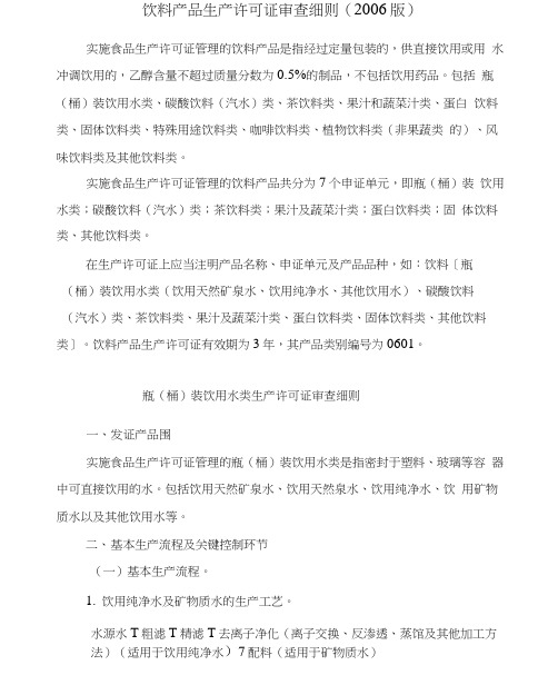
饮料产品生产许可证审查细则(2006版)实施食品生产许可证管理的饮料产品是指经过定量包装的,供直接饮用或用水冲调饮用的,乙醇含量不超过质量分数为0.5%的制品,不包括饮用药品。
包括瓶(桶)装饮用水类、碳酸饮料(汽水)类、茶饮料类、果汁和蔬菜汁类、蛋白饮料类、固体饮料类、特殊用途饮料类、咖啡饮料类、植物饮料类(非果蔬类的)、风味饮料类及其他饮料类。
实施食品生产许可证管理的饮料产品共分为7个申证单元,即瓶(桶)装饮用水类;碳酸饮料(汽水)类;茶饮料类;果汁及蔬菜汁类;蛋白饮料类;固体饮料类、其他饮料类。
在生产许可证上应当注明产品名称、申证单元及产品品种,如:饮料[瓶(桶)装饮用水类(饮用天然矿泉水、饮用纯净水、其他饮用水)、碳酸饮料(汽水)类、茶饮料类、果汁及蔬菜汁类、蛋白饮料类、固体饮料类、其他饮料类]。
饮料产品生产许可证有效期为3年,其产品类别编号为0601。
瓶(桶)装饮用水类生产许可证审查细则一、发证产品围实施食品生产许可证管理的瓶(桶)装饮用水类是指密封于塑料、玻璃等容器中可直接饮用的水。
包括饮用天然矿泉水、饮用天然泉水、饮用纯净水、饮用矿物质水以及其他饮用水等。
二、基本生产流程及关键控制环节(一)基本生产流程。
1.饮用纯净水及矿物质水的生产工艺。
水源水T粗滤T精滤T去离子净化(离子交换、反渗透、蒸馆及其他加工方法)(适用于饮用纯净水)7配料(适用于矿物质水)T杀菌T灌装封盖T灯检T成品瓶(桶)及其盖的清洗消毒2.饮用天然矿泉水及其他包装饮用水的生产工艺。
水源水7粗滤7精滤7杀菌7灌装封盖7灯检7成品f瓶(桶)及其盖的清洗消毒(二)关键控制环节。
水源、管道及设备等的维护及清洗消毒;瓶(桶)及其盖的清洗消毒;杀菌设施的控制和杀菌效果的监测;纯净水生产去离子净化设备控制和净化程度的监测;灌装车间环境卫生和洁净度的控制;包装瓶(桶)及盖的质量控制;消毒剂选择和使用;饮用矿物质水生产中,矿物质的添加量控制;操作人员的卫生管理等。
LTC3862-1资料

The operating frequency can be set with an external resistor over a 75kHz to 500kHz range and can be synchronized to an external clock using the internal PLL. Multi-phase operation is possible using the SYNC input, the CLKOUT output and the PHASEMODE control pin allowing 2-, 3-, 4-, 6- or 12-phase operation.
7 8 9 10 11 12
SGND CLKOUT
SYNC PLLFLTR SENSE2+ SENSE2–
UH PACKAGE 24-LEAD (5mm s 5mm) PLASTIC QFN
TJMAX = 150°C, θJA = 34°C/W EXPOSED PAD (PIN 25) IS PGND, MUST BE SOLDERED TO PCB
SS, PLLFLTR Voltage ................................. –0.3V to 3V8 ITH Voltage ............................................... –0.3V to 2.7V FB Voltage.................................................. –0.3V to 3V8 FREQ Voltage ............................................ –0.3V to 1.5V Operating Junction Temperature Range (Notes 3, 4)
美意三位一体机组通用说明书
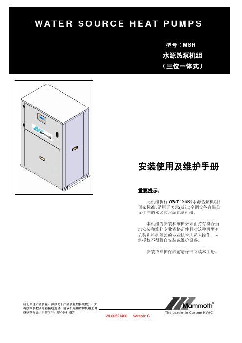
(一)机组特点 (3)(二)机组数据 (5)(三)机组安装 (6)(四)保养和维护 (9)(五)电气 (10)(六)开机运行 (11)一.机组特点(随机附件)压 力 表温 度 计下的性能参考。
一致,恕不另行通知。
1、本产品在制冷工况下,当源水侧进水温度小于20℃时,可增加流量旁通阀,可减小水流量,保证机组出水温度在25℃以上。
建议制冷工况负载侧不要长期在过高的出水温度下使用,其结果可能导致压缩机润滑油的碳化,影响压缩机的正常使用。
2、当本产品机组源水侧出水温度低于2℃,请在水系统中加入防冻液,以防机组系统冻坏。
3、在用生活热水要求出水55℃时,为保证机组的可靠运行,要求源水侧在额定水流下进水温度不低于7℃。
4、以上进出水温限定范围均在额定水流量下。
5、由于该机组采用高效板式换热器,应在冬季环境温度过低机组停用时,将水系统内水排除干净,以避免板换水路系统结冰;若机组长期不用,则必须将水系统内水排除干净,开启水泵,从排水法兰处放水或拆开后面板,从水泵放水阀放水,以免冻裂板换及水系统管路。
6、机组长期运行中的蒸发压力与冷凝压力须在下列运行极限范围内(蓝色线框内):在设置及移装空调器时,制冷循环系统内除了规定的制冷剂(R22)以外不要让空气等混入。
如有空气等混入则制冷循环6 水管连接示意图有机磷 mg/l机组内部如此线在出厂前均已完成并做好了绝缘防开机前准备 ¾ 机组安装、调试、运行、维修之前,请仔细阅读随机的安装使用说明书!首次调试必须在本公司调试工程师的指导下进行。
¾ 检查电气接线是否松动,如有松动应立即拧紧。
¾ 检查系统压力是否正常,是否有泄漏的可能。
¾ 确保相序正确,电压符合机组电源要求。
¾ 温度传感器位置合理,接触可靠。
¾ 点动源水泵确保旋向正确。
¾ 水流量符合铭牌参数¾ 机组运行前应确保所有部件无损伤,电源电压及频率、水系统正常! ¾ 电源要求按照以下要求执行:1) 允许电压范围:360~415V(GB12325规定为额定电压±7%以内) 2) 允许频率范围:±2%以内(GB/T15945规定为±0.2Hz 以内)3)允许三相电压不平衡量:±2%以内(GB12326规定为2.5%以内; GB/T15543规定为2%以内)4) 允许三相电流不平衡量:±5%以内上述准备工作均已完成任务,并确保无误,可以按下开机按钮,进入正常开机操作,此时,应密切注意机组运行态,运行指标应符合上述各条要求。
LM386-1中文资料
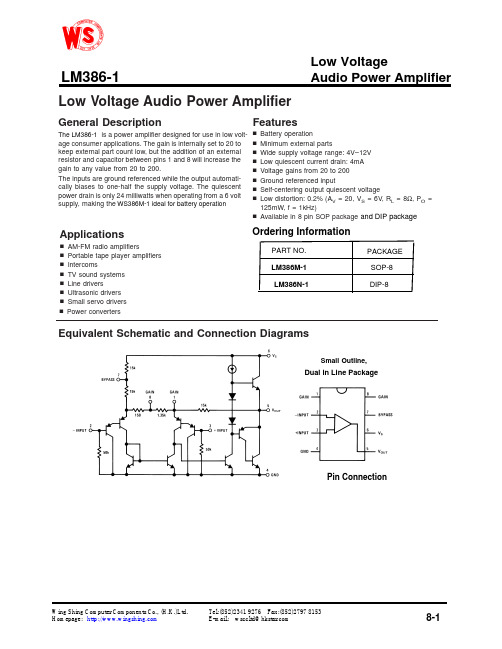
Low Voltage Audio Power AmplifierGeneral Descriptionis a power amplifier designed for use in low volt-age consumer applications.The gain is internally set to 20to keep external part count low,but the addition of an external resistor and capacitor between pins 1and 8will increase the gain to any value from 20to 200.The inputs are ground referenced while the output automati-cally biases to one-half the supply voltage.The quiescent power drain is only24milliwatts when operating from a 6volt supply,making the Featuresn Battery operationn Minimum external partsn Widesupply voltage range:4V–12V n Low quiescent current drain:4mA n Voltage gains from 20to 200n Ground referenced inputn Self-centering output quiescent voltagenLow distortion:0.2%(A V =20,V S =6V,R L =8Ω,P O =125mW,f =1kHz)n Available in 8pin SOP package Applicationsn AM-FM radio amplifiersn Portable tape player amplifiers n Intercomsn TV sound systems n Line driversn Ultrasonic drivers n Small servo drivers nPower convertersEquivalent Schematic and Connection DiagramsSmall Outline,Wing Shing Computer Components Co., (H.K.)Ltd.Tel:(852)2341 9276 Fax:(852)2797 8153Homepage: E-mail: wsccltd@Low Voltage Audio Power AmplifierWS386M-1 ideal for battery operationPin Connectionand DIP packageOrdering Information8-1LM386-1The LM386-1Note 1:All voltages are measured with respect to the ground pin,unless otherwise specified.Note 2:Absolute Maximum Ratings indicate limits beyond which damage to the device may occur.Operating Ratings indicate conditions for which the device is func-tional,but do not guarantee specific performance limits.Electrical Characteristics state DC and AC electrical specifications under particular test conditions which guar-antee specific performance limits.This assumes that the device is within the Operating Ratings.Specifications are not guaranteed for parameters where no limit isgiven,however,the typical value is a good indication of device performance.Note 3:For operation in ambient temperatures above 25˚C,the device must be derated based on a 150˚C maximum junction temperature and a thermal resistance of 170˚C/W for the small outline package.Absolute Maximum RatingsDual-In-Line Package Soldering (10sec)+260˚CSmall Outline Package (SOIC )Vapor Phase (60sec)+215˚C Infrared (15sec)+220˚CSoldering InformationSupply Voltage (WS386-1)Package Dissipation(Note3)(WS386N) 1.25W0.73W(WS386M).4V+-65 C to +150 C0 C to+70 C +150 CInput Voltage Storage TemperatureJunction TemperatureOperating Temperature -8-2Application HintsGAIN CONTROLa more versatile amplifier,two pins (1and 8)are provided for gain control.With pins 1and 8open the 1.35k Ωresistor sets the gain at 20(26dB).If a capacitor is put from pin 1to 8,bypassing the 1.35k Ωresistor,the gain will go up to 200(46dB).If a resistor is placed in series with the capacitor,the gain can be set to any value from 20to 200.Gain control can also be done by capacitively cou-pling a resistor (or FET)from pin 1to ground.Additional external components can be placed in parallel with the internal feedback resistors to tailor the gain and fre-quency response for individual applications.For example,we can compensate poor speaker bass response by fre-quency shaping the feedback path.This is done with a series RC from pin 1to 5(paralleling the internal 15k Ωresistor).For 6dB effective bass boost:R .15k Ω,the lowest value for good stable operation is R =10k Ωif pin 8is open.If pins 1and 8are bypassed then R as low as 2k Ωcan be used.This restriction is because the amplifier is only compensated for closed-loop gains greater than 9.INPUT BIASINGThe schematic shows that both inputs are biased to ground with a 50k Ωresistor.The base current of the input transis-tors is about 250nA,so the inputs are at about 12.5mV when left open.If the dc source resistance driving the LM386is higher than 250k Ωit will contribute very little additional offset (about 2.5mV at the input,50mV at the output).If the dc source resistance is less than 10k Ω,then shorting the unused input to ground will keep the offset low (about 2.5mV at the input,50mV at the output).For dc source resistances between these values we can eliminate excess offset by put-ting a resistor from the unused input to ground,equal in value to the dc source resistance.Of course all offset prob-lems are eliminated if the input is capacitively coupled.with higher gains (bypassing the 1.35k Ωresistor between pins 1and 8)it is necessary to by-pass the unused input,preventing degradation of gain and possible instabilities.This is done with a 0.1µF capacitor or a short to ground depending on the dc source resistance on the driven input.1405Gain -input +input GND GND VOUT V CC 100BYPASS Gain390101514051405120781201201205506006007504404A 4B 5623Coordinates Pad N Pad Name X Y 975665100Pad Location Coordinates18-3LM386-1To make LM386-1When using LM386-1Typical Performance CharacteristicsQuiescent Supply Current vs SupplyVoltagePower Supply Rejection Ratio (Referred to the Output)vsFrequencyPeak-to-Peak Output Voltage Swing vs SupplyVoltageVoltage Gain vsFrequencyDistortion vsFrequencyDistortion vs OutputPowerDevice Dissipation vs Output Power —4ΩLoadDevice Dissipation vs Output Power —8ΩLoad Device Dissipation vs Output Power —16ΩLoad8-4LM386-1Typical ApplicationsAmplifier with Gain =20MinimumPartsAmplifier with Gain =200Amplifier with Gain =50Low Distortion Power WienbridgeOscillatorAmplifier with BassBoostSquare WaveOscillator8-5LM386-1Typical Applications(Continued)Note 4:Twist Supply lead and supply ground very tightly.Note 5:Twist speaker lead and ground very tightly.Note 6:Ferrite bead in Ferroxcube K5-001-001/3B with 3turns of wire.Note 7:R1C1band limits input signals.Note 8:All components must be spaced very closely to IC.Frequency Response with Bass BoostAM Radio PowerAmplifier8-6LM386-1Physical Dimensionsinches (millimeters)unless otherwise noted(Continued)Dual-In-Line Package8-7LM386N-1Physical Dimensionsinches (millimeters)unless otherwisenotedSO Package8-8LM386M-1。
二00八年三月份第三周消防产品及防火建材质量检验情况
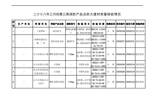
郴州宏华消防器材经营部
消防应急照明灯
LX-08A
外观质量、主要部件性能、基本功能等
GB17945-2000
不合格
20080265
20080320
委托检验
25
/
郴州市诚成消防器材经营部
消防应急照明灯
KHEL5C-2
外观质量、主要部件性能、基本功能等
GB17945-2000
合 格
20080267
20080320
GB6246-2001
合 格
20080272
20080319
委托检验
15
/
长沙中天广场
防火涂料处理木材
/
外观、涂层厚度、泡层高度
GA588-2005
GB12441-1998
合 格
20080274
20080319
委托检验
16
/
长沙中天广场
石膏板
/
不燃性试验
GB8624-1997
GB/T5454-1999
MFZ/ABC1
喷射性能、外观质量、水压强度等
GB 4351.1-2005
GB 4351.3-2005
合 格
20080264
20080319
委托检验
9
/
郴州锐定物资供应部
室内消火栓
SN50型
外观质量、强度、密封性能、开启高长等
GB3445-2005
GB12514.1-2005
不合格
20080266
20080319
合 格
20080275
20080319
委托检验
17
/
株洲市荷塘区欧啦啦量贩式数码歌城
UC3862中文资料

UC2861-2868UC3861-3868FEATURES•Controls Zero Current Switched (ZCS)or Zero Voltage Switched (ZVS)Quasi-Resonant Converters •Zero-Crossing Terminated One-ShotTimer•Precision 1%, Soft-Started 5V Reference•Programmable Restart Delay Following Fault •Voltage-Controlled Oscillator (VCO)with Programmable Minimum andMaximum Frequencies from 10kHz to 1MHz•Low Start-Up Current (150µA typical)•Dual 1 Amp Peak FET Drivers •UVLO Option for Off-Line or DC/DCApplicationsDESCRIPTIONThe UC1861-1868family of ICs is optimized for the control of Zero Cur-rent Switched and Zero Voltage Switched quasi-resonant converters.Dif-ferences between members of this device family result from the variouscombinations of UVLO thresholds and output options.Additionally,the one-shot pulse steering logic is configured to program either on-time for ZCS systems (UC1865-1868),or off-time for ZVS applications (UC1861-1864).The primary control blocks implemented include an error amplifier to com-pensate the overall system loop and to drive a voltage controlled oscillator (VCO),featuring programmable minimum and maximum frequencies.Trig-gered by the VCO,the one-shot generates pulses of a programmed maxi-mum width,which can be modulated by the Zero Detection comparator.This circuit facilitates “true”zero current or voltage switching over variousline,load,and temperature changes,and is also able to accommodate the resonant components' initial tolerances.Under-Voltage Lockout is incorporated to facilitate safe starts uponpower-up.The supply current during the under-voltage lockout period istypically less than 150µA,and the outputs are actively forced to the low state.(continued)BLOCK DIAGRAMResonant-Mode Power Supply ControllersDevice18611862186318641865186618671868UVLO 16.5/10.516.5/10.5360143601416.5/10.516.5/10.53601436014Outputs Alternating Parallel Alternating Parallel Alternating Parallel Alternating Parallel “Fixed”Off TimeOff TimeOff TimeOff TimeOn TimeOn TimeOn TimeOn TimeABSOLUTE MAXIMUM RATINGSV CC . . . . . . . . . . . . . . . . . . . . . . . . . . . . . . . . . . . . . . . . . . .22V Output CurrentSource or Sink (Pins 11 & 14). . . . . . . . . . . . . . . . . . . . .0.5A DC Pulse (0.5µs). . . . . . . . . . . . . . . . . . . . . . . . . . . . . . .1.5A Power Ground Voltage. . . . . . . . . . . . . . . . . . . . . . . . . . .±0.2V Inputs (Pins 2, 3, 10, & 15). . . . . . . . . . . . . . . . . . . .–0.4 to 7V Error Amp Output Current . . . . . . . . . . . . . . . . . . . . . . . .±2mA Power Dissipation . . . . . . . . . . . . . . . . . . . . . . . . . . . . . . . .1W Junction Temperature (Operating). . . . . . . . . . . . . . . . . .150°C Lead Temperature (Soldering, 10 seconds). . . . . . . . . .300°CAll voltages are with respect to signal ground and all currents are positive into the specified terminal. Pin numbers refer to the J and N packages. Consult Unitrode Integrated Circuits da-tabook for information regarding thermal specifications andlimitations of packages.CONNNECTION DIAGRAMSDESCRIPTION (cont.)UVLO thresholds for the UC1861/62/65/66are 16.5V (ON)and 10.5V (OFF),whereas the UC1863/64/67/68thresholds are 8V (ON)and 7V (OFF).After V CC ex-ceeds the UVLO threshold,a 5V generator is enabled which provides bias for the internal circuits and up to 10mA for external usage.A Fault comparator serves to detect fault conditions and set a latch while forcing the output drivers low.The Soft-Ref pin serves three functions:providing soft start,re-start delay, and the internal system reference.Each device features dual 1Amp peak totem pole output drivers for direct interface to power MOSFETS.The out-puts are programmed to alternate in the UC1861/63/65/67devices.The UC1862/64/66/68out-puts operate in unison alllowing a 2 Amp peak current.ELECTRICAL CHARACTERISTICS Unless otherwise stated, all specifications apply for –55°C≤T A≤125°C for theUC186x, –25°C≤T A≤85°C for the UC286x, and 0°C≤T A≤70°C for the UC386x, V CC=12V, C VCO=1nF, Range=7.15k, R MIN=86.6k, C=200pF, R=4.02k, and Csr=0.1µF. T A=T J .PARAMETER TEST CONDITIONS MIN TYP MAX UNITS 5V GeneratorOutput Voltage12V≤Vcc≤20V, –10mA≤I O≤0mA 4.8 5.0 5.2V Short Circuit Current V O= 0V–150–15mA Soft-ReferenceRestart Delay Current V = 2V102035µA Soft Start Current V = 2V–650–500–350µA Reference Voltage T J= 25°C, I O= 0A 4.95 5.00 5.05V12V≤V CC≤20V, –200µA≤I O≤200µA 4.85 5.15V Line Regulation12V≤V CC≤20V220mV Load Regulation–200µA≤I O≤200µA1030mV Error Amplifier (Note 3)Input Offset Voltage V CM= 5V, Vo = 2V, I O= 0A–1010mV Input Bias Current V CM= 0V–2.0–0.3µA Voltage Gain Vcm = 5V, 0.5V≤V O≤3.7V, I O= 0A70100dB Power Supply Rejection Ratio Vcm = 5V, V O= 2V, 12V≤V CC≤20V70100dB Error Amplifier (Note 3) (cont.)Common Mode Rejection Ratio0V≤Vcm≤6V, V O= 2V65100dB V OUT Low V ID= –100mV, I O= 200µA0.170.25V V OUT High V ID= 100mV, I O= –200µA 3.9 4.2V Unity Gain Bandwidth(Note 4)0.50.8MHz Voltage Controlled OscillatorMaximum Frequency V ID(Error Amp) = 100mV, T J= 25°C450500550kHzV ID(Error Amp) = 100mV425575kHz Minimum Frequency V ID(Error Amp) = –100mV, T J= 25°C455055kHzV ID(Error Amp) = –100mV4258kHz One ShotZero Comparator Vth0.450.500.55V Propagation Delay(Note 4)120200ns Maximum Pulse Width V ZERO= 1V85010001150ns Maximum to Minimum Pulse V ZERO= 0V UCx861 – UCx864 2.54 5.5 Width Ratio V ZERO= 0V UCx865 – UCx868. –55°C to +85°C4 5.57V ZERO= 0V UCx865 – UCx868, +125°C 3.8 5.57Output StageRise and Fall Time C LOAD= 1nF (Note 4)2545ns Output Low Saturation I O= 20mA0.20.5VI O= 200mA0.5 2.2VOutput High Saturation I O= –200mA, down from Vcc 1.7 2.5V UVLO Low Saturation I O= 20mA0.8 1.5V Fault ComparatorFault Comparator Vth 2.85 3.00 3.15V Delay to Output(Note 4) (Note 5)100200nsELECTRICAL CHARACTERISTICS Unless otherwise stated, all specifications apply for –55°C≤T A≤125°C for theUC186x, –25°C≤T A≤85°C for the UC286x, and 0°C≤T A≤70°C for the UC386x, V CC=12V, C VCO=1nF, Range=7.15k, R MIN=86.6k, C=200pF, R=4.02k, and Csr=0.1µF. T A=T J .PARAMETER TEST CONDITIONS MIN TYP MAX UNITS UVLOVcc Turn-on Threshold UCx861, UCx862, UCx865, UCx8661516.518VUCx863, UCx864, UCx867, UCx86878.09V Vcc Turn-off Threshold UCx861, UCx862, UCx865, UCx8669.510.511.5VUCx863, UCx864, UCx867, UCx86867.08V Icc Start V CC= V CC(on) – 0.3V150300µA Icc Run V ID= 100mV2532mANote 1: Currents are defined as positive into the pin.Note 2: Pulse measurement techniques are used to insure that T J= T A.Note 3: VID = V(NI) – V(INV).Note 4: This parameter is not 100% tested in production but guaranteed by design.Note 5: Vi = 0 to 4V tr(Vi)10ns tpd = t(Vo = 6V) – t(Vi = 3V)UVLO&5V GENERATOR(See Figure1):When power is applied to the chip and Vcc is less than the upper UVLO threshold,Icc will be less than300µA,the5V gen-erator will be off, and the outputs will be actively held low.When Vcc exceeds the upper UVLO threshold,the5V generator turns on.Until the5V pin exceeds4.9V,the outputs will still remain low.The5V pin should be bypassed to signal ground with a 0.1µF capacitor.The capacitor should have low equiva-lent series resistance and inductance.FAULT AND SOFT-REFERENCE(See Figure1):The Soft-Ref pin serves three functions:system reference,re-start delay,and soft-start.Designed to source or sink 200µA,this pin should be used as the input reference for the error amplifier circuit.This pin requires a bypass ca-pacitor of at least0.1µF.This yields a minimum soft-start time of 1ms.Under-Voltage Lockout sets both the fault and restart de-lay latches.This holds the outputs low and discharges the Soft-Ref pin.After UVLO,the fault latch is reset by the low voltage on the Soft-Ref pin.The reset fault latch resets the delay latch and Soft-Ref charges via the0.5mA current source.The fault pin is input to a high speed comparator with a threshold of3V.In the event of a detected fault,the fault latch is set and the outputs are driven low.If Soft-Ref is above4V,the delay latch is set.Restart delay is timed as Soft-Ref is discharged by20µA.When Soft-Ref is fully discharged,the fault latch is reset if the fault input signal is low.The Fault pin can be used as a system shutdown pin.If a fault is detected during soft-start,the fault latch is set and the outputs are driven low.The delay latch will re-main reset until Soft-Ref charges to4V.This sets the de-lay latch,and restart delay is timed.Note that restart delay for a single fault event is longer than for recurring faults since Soft-Ref must be discharged from5V instead of 4V.The restart delay to soft-start time ratio is24:1for a fault occurring during normal operation and19:1for faults oc-curring during soft-start.Shorter ratios can be pro-grammed down to a limit of approximately3:1by the addition of a20kΩor larger resistor from Soft-Ref to ground.A100kΩresistor from Soft-Ref to5V will have the effect of permanent shut down after a fault since the internal 20µA current source can't pull Soft-Ref low.This feature can be used to require recycling Vcc after a fault.Care must be taken to insure Soft-Ref is indeed low at start up, or the fault latch will never be reset.APPLICATION INFORMATIONAPPLICATION INFORMATIONMinimum oscillator frequency is set by Rmin and Cvco.The minimum frequency is approximately given by the equation:F R C MIN MIN VCO≅43.•Maximum oscillator frequency is set by Rmin,Range &Cvco.The maximum frequency is approximately given by the equation:F R Range C MAX MINVCO≅33.(//)•The Error Amplifier directly controls the oscillator fre-quency.E/A output low corresponds to minimum fre-quency and output high corresponds to maximum frequency.At the end of each oscillator cycle,the RC pin is discharged to one diode drop above ground.At the be-ginning of the oscillator cycle,V(RC)is less than Vth1and so the output of the zero detect comparator is ig-nored.After V(RC)exceeds Vth1,the one shot pulse will be terminated as soon as the zero pin falls below 0.5V or V(RC)exceeds Vth2.The minimum one shot pulse width is approximately given by the equation:Tpw(min)0.3R C.The maximum pulse width is approximately given by:Tpw(max)1.2RC.APPLICATION INFORMATIONdual non-overlapping square waves at outputs A &B.This is suited to drive dual switch ZVS systems.STEERING LOGICinverted pulse trains occurring identically at both output pins.This is suited to drive single switch ZVS systems.Both outputs are available to drive the same MOSFET gate.It is advisable to join the pins with 0.5 ohm resistors.alternating pulse trains at outputs A & B. This is suited to drive dual switch ZCS systems.non-inverted pulse trains occurring identically at both output pins.This is suited to drive single switch ZCS systems.Both outputs are available to drive the same MOSFET gate.It is ad-visable to join the pins with 0.5 ohm resistors.APPLICATION INFORMATION (cont.)UNITRODE CORPORATION7 CONTINENTAL BLVD. • MERRIMACK, NH 03054TEL. (603) 424-2410 • FAX (603) 424-3460IMPORTANT NOTICETexas Instruments and its subsidiaries (TI) reserve the right to make changes to their products or to discontinue any product or service without notice, and advise customers to obtain the latest version of relevant information to verify, before placing orders, that information being relied on is current and complete. All products are sold subject to the terms and conditions of sale supplied at the time of order acknowledgement, including those pertaining to warranty, patent infringement, and limitation of liability.TI warrants performance of its semiconductor products to the specifications applicable at the time of sale in accordance with TI’s standard warranty. Testing and other quality control techniques are utilized to the extent TI deems necessary to support this warranty. Specific testing of all parameters of each device is not necessarily performed, except those mandated by government requirements.CERTAIN APPLICATIONS USING SEMICONDUCTOR PRODUCTS MAY INVOLVE POTENTIAL RISKS OF DEATH, PERSONAL INJURY, OR SEVERE PROPERTY OR ENVIRONMENTAL DAMAGE (“CRITICAL APPLICATIONS”). TI SEMICONDUCTOR PRODUCTS ARE NOT DESIGNED, AUTHORIZED, OR WARRANTED TO BE SUITABLE FOR USE IN LIFE-SUPPORT DEVICES OR SYSTEMS OR OTHER CRITICAL APPLICATIONS. INCLUSION OF TI PRODUCTS IN SUCH APPLICATIONS IS UNDERSTOOD TO BE FULLY AT THE CUSTOMER’S RISK.In order to minimize risks associated with the customer’s applications, adequate design and operating safeguards must be provided by the customer to minimize inherent or procedural hazards.TI assumes no liability for applications assistance or customer product design. TI does not warrant or represent that any license, either express or implied, is granted under any patent right, copyright, mask work right, or other intellectual property right of TI covering or relating to any combination, machine, or process in which such semiconductor products or services might be or are used. TI’s publication of information regarding any third party’s products or services does not constitute TI’s approval, warranty or endorsement thereof.Copyright © 1999, Texas Instruments Incorporated。
最全LM386中文资料
LM386 中文资料 PDF简介:LM386 中文资料 PDF 是专为低损耗电源所设计的功率放大器集成电路。
它的内建增益为20,透过pin 1 和pin8 位间电容的搭配,增益最高可达200。
LM386可使用电 ...是专为低损耗电源所设计的功率放大器集成电路。
它的内建增益为20,透过pin 1 和pin8脚位间电容的搭配,增益最高可达200。
LM386可使用电池为供应电源,输入电压范围可由4V ~12V,无作动时仅消耗4mA电流,且失真低。
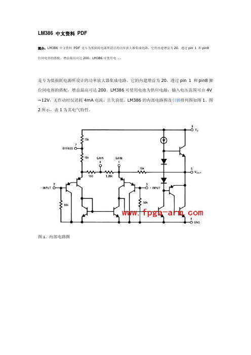
LM386的内部电路图及引脚排列图如图1、图2所示,表1为其电气特性。
图1. 内部电路图图2 引脚功能图极限参数:电源电压(LM386N-1,-3,LM386M-1)15V 电源电压(LM386N-4)22V封装耗散(LM386N)1.25W(LM386M)0.73W(LM386MM-1)0.595W输入电压±0.4V储存温度-65℃至+150℃操作温度0℃至+70℃结温+150℃焊接信息焊接(10秒)260℃小外形封装(SOIC 和MSOP ) 气相(60秒)215℃ 红外(15秒)220℃ 热电阻qJC (DIP )37℃/W qJA (DIP )107℃/W qJC (SO 封装)35℃/W qJA (SO 封装)172℃/W qJA (MSOP 封装)210℃/W qJC (MSOP 封装)56℃/W表1. LM386电气特性Parameter 参数测试条件 最小 典型 最大 单位Operating Supply Voltage (VS) 操作电源电压-LM386N-1,-3,LM386M-1,LM386MM-1 4-12VLM386N-4-5- 18 V Quiescent Current (IQ) 静态电流 VS = 6V, VIN =048mAOutput Power (POUT) 输出功率 --LM386N-1,LM386M-1,LM386MM-1VS = 6V, RL =8W, THD = 10% 250 325 - mWLM386N-3VS = 9V, RL =8W, THD = 10%500700-mW LM386N-4VS=16V, RL =32W, THD = 10%7001000-mWVS = 6V, f = 1 kHz26-dB Voltage Gain (AV) 电压增益10 μF from Pin 1 to 846-dB Bandwidth (BW) 宽带VS = 6V, Pins 1 and 8 Open300-kHzTotal Harmonic Distortion (TH D)总谐波失真VS = 6V, RL =8W,POUT = 125mW f = 1 kHz, Pins 1 and 8 Open-0.2-%Power Supply Rejection Ratio (PSRR) 电源抑制比VS=6V, f=1kHz, CBYPASS =10 μF Pins 1 and 8 Open,Referred toOutput-50-dBInput Resistance (RIN) 输入电阻--50-kΩInput Bias Current (IBIAS) 输入偏置电流VS = 6V, Pins 2 and 3 Open-250-nA LM386低电压音频功率放大器的工作原理与典型应用电路图概述(Description):LM386是美国国家半导体公司生产的音频功率放大器,主要应用于低电压消费类产品。
Philips Pure Taste WP3861 瓶颈纸筒纯水器说明书
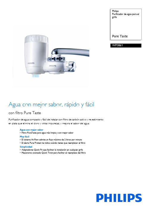
PhilipsPurificador de agua para elgrifoWP3861Agua con mejor sabor, rápido y fácilcon filtro Pure TastePurificador de agua compacto y fácil de instalar con filtro de carbón activo y revestimientoen plata que elimina el cloro y otras impurezas, y mejora el sabor del agua.Agua con mejor sabor•Filtro PureTaste para agua más limpia y con mejor saborMuy fácil•El sistema Hi-Flow admite un flujo máximo de 2 litros por minuto•El alerta Pure Protect te indica cuándo tienes que reemplazar el filtroSimplicidad•Adaptadores Quick Fit que facilitan la instalación en cualquier grifo•Mecanismo avanzado Quick Twist para facilitar el reemplazo del filtroFecha de publicación2023-03-16Versión: 5.7.1© 2023 Koninklijke Philips N.V.Todos los derechos s especificaciones quedan sujetas a modificaciones sin previo aviso. Las marcas comerciales son propiedad deKoninklijke Philips N.V. o sus respectivos titulares. EspecificacionesPurificador de agua para el grifo Pure TasteDestacados Filtro Pure Taste El filtro PureTaste elimina el cloro, el mal sabor, los olores desagradables y los sedimentos del agua corriente y garantiza un agua más limpia y con mejor sabor para beber, cocinar y limpiar frutas y vegetales. Además, el carbón activado revestido en plata evita el desarrollo de bacterias en el interior del filtro para que disfrutes del agua con más seguridad.Alerta Pure Protect El alerta Pure Protect es una etiqueta con los meses del año que puede adherirse fácilmente a la cubierta del filtro. Sólo tienes que marcar el mes de reemplazo para que el alerta te indique cuándo hacer el cambio. Ahora vas a disfrutar del agua más pura siempre.Hi-Flow Este purificador compacto ofrece un flujo máximo de dos litros por minuto, prácticamente igual al flujo normal del agua no filtrada. Además, con sólo rotar la palanca de selección, puedes elegir entre el chorro o rociador de agua no filtrada o el rociador de agua filtrada.Adaptadores para grifos Quick Fit Este purificador de agua avanzado trae varios adaptadores Quick Fit hechos a medida para facilitar la instalación del purificador en el grifo. Simple y práctico, para cumplir con nuestro lema "Sense and Simplicity".Sistema QuickTwist de cambio de filtro El sistema de reemplazo avanzado Quick Twist hace que el cambio del filtro sea rápido, simple y seguro, para que disfrutes de tu purificador de agua sin complicaciones.Sistema purificador •Reducción de turbiedad: 3000 litros o aprox. 1 año •Eliminación de cloro: >75 %Especificaciones de diseño •Colores:blanco •Materiales: plástico •Peso del producto: 260 g •Dimensiones del producto (Lo x An x Al): 65 x 143 x 106 mmEspecificaciones del filtro •Vida útil del filtro: 6 meses o 2000 l aproximadamente •Principales componentes del filtro: revestimiento en plata GACCondiciones del agua de entrada •Presión mínima del agua de entrada: 0,7 bar•Temperatura máxima de entrada de agua: 50 °C •Presión máxima del agua de entrada: 3,5 bar Especificaciones generales •Accesorios: 9 adaptadores QickFit para todo tipo de grifos y alerta PureProtect •Cartucho de filtro de repuesto: WP3961•Selección de agua: rociador con filtro, rociador sin filtro, corriente sin filtro •Velocidad del flujo de agua: 2 l/min •Velocidad del flujo de agua: 5 °C Sustentabilidad •Empaque: > 90% de materiales reciclados •Manual del usuario: 100% de papel reciclado País de origen •Purificadores de agua: Japón •Filtro de repuesto: Japón。
国家质检总局和国家认证认可监督管理委员会发布《第一批实施强制性产品认证的产品目录》中产品的适用范围
国家质检总局和国家认证认可监督管理委员会发布《第一批实施强制性产品认证的产品目录》中产品的适用范围
佚名
【期刊名称】《轻工标准与质量》
【年(卷),期】2002(000)005
【总页数】4页(P6-9)
【正文语种】中文
【中图分类】F768
【相关文献】
1.第一批实施强制性产品认证的产品目录 [J],
2.关于印发《〈第一批实施强制性产品认证的产品目录〉中部分产品详细适用范围》的通知 [J],
3.国家质量监督检验检疫总局和国家认证认可监督管理委员会发布的《第一批实施强制性产品认证的产品目录》 [J],
4.国家公布第一批实施强制性产品认证产品目录 [J],
5.国家质检总局发布《第一批实施强制性产品认证的产品目录》 [J],
因版权原因,仅展示原文概要,查看原文内容请购买。
金属切割机床-其它类机床

机床参数>>金属切割机床>>其它类机床管子切断机床产品名称型号工件直径范围(毫米)最大切管长度(毫米)主轴转速工作精度电机净重外形尺寸长×宽×高(毫米)生产厂级数范围(转/分)垂直度粗糙度(微米)主电机总容量管子切断机床Q11106002110-2000.1/1000.4-3.23 3.6411500×900×1400应城机床厂Q111120-11450-5001275-6007.510.232.861950×1330×1647芜湖重型机床厂QB111020-9012002110-2200.1/1000.4-3.235 2.752560×1150×1800应城机床厂Q1115A38-1524501136.5-3740.16/1006.4-3.21316.7362570×1650×1883薄壁管子切断机床Q116J43-653502180-2603 4.6 1.21270×760×1215机床参数>>金属切割机床>>其它类机床多刀切割机产品名称型号技术参数电机净重外形尺寸长×宽×高(毫米)生产厂主电机总容量多刀切割机B2-097刀架行程86-200(20级)往复运动速度5-120次/分钟刀组宽度200.1.1 1.5 1.11700×760×2060北京第二机床厂机床参数>>金属切割机床>>其它类机床管子加工专用机床产品名称机床型号加工对象完成的工艺内容机床生产效率工作精度主要技术参数生产厂管螺纹车床SI-245A石油套管、油管钻杆等端部车螺纹车削或车螺纹表面粗糙度1.6µm螺纹精度达API加工直径60-210;主轴孔径240沈阳第一机床厂SI-262石油套管、油管钻杆等端部车螺纹车削或车螺纹表面粗糙度1.6µm螺纹精度达API加工直径114-340;主轴孔径355管子切断机床SI-295石油套管、油管钻杆等切断70-110头/时加工表面粗糙度12.5µm加工直径42-159;主轴孔径180管端自动车床SI-276无缝钢管端部的加工车削内外圆和端部侧内外棱90-160头/时加工表面粗糙度12.5µm加工直径25-152刀盘转速140-1250r/min管接头数控车床SI-284石油套管接头、石油油管接头内孔两端锥螺纹加工20-30件/时表面粗糙度1.6µm螺纹精度达API加工直径油管2"-4½"主轴转速130-790r/min保护环数控车床SI-277油、套管保护环内外保护环车削与螺纹加工60-80件/时表面粗糙度1.6µm螺纹精度达API加工直径73 140主轴转速165-800r/min机床参数>>金属切割机床>>其它类机床无心车床产品名称型号工件毛坯直径(mm)加工工件直径(mm)加工工件长度(mm)主轴转速进给滚轮上下行距电机净重外形尺寸长×宽×高(毫米)生产厂级数范围(转/分)主电机总容量无心磨床Q3810¢25-105¢20-1003000-150001840-5604020/3037.430(基型)1730×314×178(基型)青海重型机床厂机床参数>>金属切割机床>>其它类机床圆刻线机产品名称型号最大加工直径(毫米)刻线最大长度加工公件最大重量刀架最大升降移动量分度头底座最大移动量每分钟刻线数生产厂圆刻线机Q4003300185kg200MM200MM60宁江机床厂机床参数>>金属切割机床>>其它类机床感应淬火机 中频淬火机产品名称型号最大加工直径(毫米)最大夹持长度(毫米)连续加热长度(毫米)零件移动速度范围(mm/s)零件旋转速度(r/min)零件快速返回速度(mm/s)零件最大下降速度(mm/s)零件最大重量(公斤)电机净重外形尺寸 长×宽×高 (毫米)生产厂总容量台数通用感应淬火机GC1080A 4008008001-3020-150******** 2.2 0.18590×1466×2560天津第九机床厂GC1080(双工位)400 单轴800半自动760手动8001-2020-2008015080 2.5 0.21998×700×2440GCt10120A 400120012001-3020-150******** 2.5 0.2590×1486×3370GC10180Q 500180018001-3020-150******** 2.50.251610×800×4560半轴感应淬火机GC10120A/2400120012001-2020-2001-601151002.450.2590×1966×3370曲轴淬火机床GC12100回转直径2201000100030/160 180 0.6GC12150回转直径3001500150030/60 600/4件8.3 0.453725×1800×2785GC12200回转直径35020002000 30/60 600/4件10 0.64225×1800×2785凸轮轴感应淬火机GC10120 A/3 凸轮轴1000凸轮轴10001-30110606050 2.20.222064×1300×3370针杆全自动感应淬火机GC111515110-300110-3001.11760×960×1050机床参数>>金属切割机床>>其它类机床齿轮高频淬火机产品名称型号零件淬火直径范围(毫米)零件淬火最大高度(毫米)零件上下移动速度(毫米/s)零件旋转速度r-min变压器上下移动速度(毫米/s)变压器前后移动速度(毫米/s)最大零件重量(公斤)重量(吨)外形尺寸(长×宽×高)(毫米)生产厂齿轮淬火机床GC13060<600200上升90下降0-150快速20-150慢速0.1-11000.11200×1400×1200天津第九机床厂GC13080<800300快速150快速1-20快速20-150慢速0.1-10-1501500.33035×2240×2570GC13200600-2000300线速度600mm/s线速度2-20mm/s快速60、慢速2-20快速60、慢速2-2010000.355643×3360×2570齿轮埋油淬火机床JC161500产品名称型号加热方式制件回转半径mm分度速度工作台高度(毫米)工作台直径(毫米)外形尺寸(长×宽×高)(毫米)生产厂螺钉头淬火机床GC13100/1周期性一次加热每次一件435.55-50转/分12-0.13秒/转0.5-0.06秒/每等分11357752105×1142×1700天津第九机床厂摇臂淬火机床GC13100/2周期性一次加热每次二十件412.55-50转/分12-0.13秒/转1.5-0.016秒/每等分11357752105×2070×2000机床参数>>金属切割机床>>其它类机床轮辋焊渣切割机产品名称型号加工轮网规路(毫米)切割焊渣尺寸(毫米)刀具转速(转/分)工件最大夹紧力(吨)夹紧钳口行程(毫米)下钳口调正量(毫米)上刀轴调整量(毫米)上下刀轴中心距离(毫米)下刀轴轴心距地面距离(毫米)每一自动循环时间(秒)电机功率(千瓦)重量(吨)外形尺寸(长×宽×高)(毫米)生产厂直径宽度宽高轮辋焊渣切割机J2-057440-510210-25013-158-104050701040225-2651250<62217.52570×2880×2860济南第二机床厂页码,1/1参数表--其它类机床(1)机床参数>>金属切割机床>>其它类机床塑料注射成型机产品名称型号螺纹编号螺杆直径(mm)注射压力(kg/On²)每次注射量(g)螺杆长径比L:D注射率(co/szc)塑化能力(kg/nr)螺杆行程(毫米)螺杆转速(r.p.m)锁模力(tons)锁模行程(毫米)模板最大开距(毫米)容模量最小最大(毫米)拉杆内距(毫米)液压顶出力(tons)顶出行程(毫米)液压系统压力(kg/cm²)油泵电机功率(千瓦)电热功率(千瓦)电源需求(A)温度控制区油箱容量(L)机器重量(tons)射台推力(tons)外形尺寸(长×宽×高)(毫米)生产厂塑料注射成型机E-180A50180035021:1136842025-140180400880200-480490×4204.36100140221370436+08.55.65100×1200×1900南京第二机床厂E-180B55150042619:11651082025-140180400880200-480490×4204.3610014022137043608.55.65100×1200×1900E-180C60125050917:11961362025-140180400880200-480490×4204.3610014022137043608.55.65100×1200×1900E-210A55170048120:11541152275-150210460960200-500520×4504.3610014022157344009.58.75400×1300×1900E-210B60145056819:11831452275-150210460960200-500520×4504.3610014022157344009.58.75400×1300×1900E-210C61115071017:12281912275-150210460960200-500520×4504.3610014022157344009.58.75400×1300×1900机床参数>>金属切割机床>>其它类机床电焊条涂料机、板牙攻丝机产品名称型号最大工件直径(毫米)加工范围工件转速 (转/分)电机净重外形尺寸 长×宽×高 (毫米)生产厂直径 (毫米)主电机总容量电焊条涂料机TL-252-62-60-136/min 2.2 2.450.81560×620×1200成都工业大学机电厂HYT-452-62-675/min 5.5 5.921800×700×1300焊条涂料压坯机HYB-1084 1/min 2.2 2.211100×520×1200板牙攻丝机S4712-2124-27100-2000.8/1.11.6/2.20.81000×800×1600S4727-22712-2745-75 2.2 2.211400×1050×2050产品名称型号规格清洗另件最大尺寸(宽×高mm)输送速度 米/分输送带高度 (毫米)承载能力 (kg/m ²)功率(千瓦)重量(吨)外形尺寸(长×宽×高)(毫米)生产厂自动通过式清洗机QXLT40-I 400×2500.985030019(电)4(汽) 1.52400×1150×1750江南清洗厂QXLT70-Ⅱ400×2500.985030038(电)8(汽) 2.53950×1150×1750QXLT70-I 700×560无级调速造1060(国际标准)700109(电)18(汽)44100×1900×2400QXLT70-Ⅱ700×560无级调速1060(国际标准)700215(电)33(汽)5.56400×1900×2400QXLT100-I 1000×800无级调速1060(国际标准)100025(汽)65000×2700×2500QXLT100/Ⅱ1000×800无级调速1060(国际标准)100047(汽)87900×2700×2500自动通过式精密清洗机QXJT 8≥10;¢≤700.9510553008.2532950×1250×1410通专两用清洗机QXTZ 650×6500.5881060(国际标准)10003576500×2800×2700机床参数>>金属切割机床>>其它类机床BSJ-2-1标准试验搅拌机产品名称型号釜体直径(毫米)桨叶转速(转/分)扭矩计量程(公斤力/米)最大升降行程(毫米)釜体水平移动距离(毫米)电机重量(吨)外形尺寸(长×宽×高)(毫米)生产厂主电机总容量台数标准搅拌试验机BSJ13000-1800(无级)0.2另订30000.750.7510.61338×488×2104浙江温岭机床厂BSJ23000-1800(无级)0.2另订300X=Y=750.750.7510.61151×730×2104机床参数>>金属切割机床>>其它类机床SYF-1双轴异桨复动搅拌机产品名称型号釜体容积(米³)低速轴转速(转/分)高速轴转速(转/分)复动行程(毫米)复动次数(次/分)桨叶上升高度(毫米)适用工作物料粘度(厘泊)电机重量(吨)外形尺寸(长×宽×高)(毫米)生产厂活动釜固定釜主电机低速轴总容量台数双轴异桨复动搅拌机SYE10.8,0.40.8≤200(无级)1000≤200≤20≤1140≤40000157.525.5332980×1150×2800浙江温岭机床厂机床参数>>金属切割机床>>其它类机床DRJ-395胶乳分离机产品名称型号转鼓内径(毫米)分离因数转鼓转速(转/分)处理量(公斤/小时)电机重量(吨)外形尺寸(长×宽×高)(毫米)生产厂主电机总容量台数胶乳分离机DET-39539510890707532011111 1.31270×843×1665浙江温岭机床厂机床参数>>金属切割机床>>其它类机床活塞推料离心机产品名称型号转鼓内径(毫米)转鼓过滤区长度(毫米)分离因数转鼓转速(转/分)装料限度(公斤)筛间间隙(毫米)推料行程(毫米)推料往复次数(次/分)生产能力(吨/时)电机重量(吨)外形尺寸(长×宽×高)(毫米)生产厂主电机总容量台数活塞推料离心机WH-800800400189.323650.850700.30-0.3540≤25 5.51724.52 3.32270×1660×1400浙江温岭机床厂。
轻便消防水龙
轻便消防水龙GA 180-1998前言本标准是根据轻便消防水龙的结构特点和技术特性,参考了相关的国家标准,并在此基础上进行技术分析和经过验证试验后形成的。
本标准为轻便消防水龙产品的研究开发、推广应用以及质量监督管理提供了全国统一的技术依据和要求。
本标准自实施之日起,轻便消防水龙产品均应符合本标准的要求。
本标准的附录A 是提示的附录。
本标准由中华人民共和国公安部提出。
本标准由全国消防标准化技术委员会第二分技术委员会归口。
本标准主要起草单位:公安部天津消防科学研究所、北京泰克新利汽车用品有限责任公司。
本标准主要起草人:石万明、迟立发、艾红新、王舒艳。
中华人民共和国公共安全行业标准GA 180-1998轻便消防水龙Portable hose assemblies1 范围本标准规定了轻便消防水龙的产品型号、技术要求、试验方法、检验规则、标志、包装、运输及储存等。
本标准适用于轻便消防水龙的生产和检验。
2 引用标准下列标准所包含的条文,通过在本标准中引用而构成为本标准的条文。
本标准出版时,所示版本均为有效。
所有标准都会被修订,使用本标准的各方应探讨使用下列标准最新版本的可能性。
GB 197-81 普通螺纹公差与配合(直径1~355 mm)GB 1048-90 管道元件公称压力GB/T 1804-92 一般公差线性尺寸的未注公差GB 3192-82 高强度铝合金挤压棒GB 3452.1-92 液压气动用O 型橡胶密封圈尺寸系列及公差GB 3452.2-87 O 型橡胶密封圈外观质量检验标准GB 6246-86 有衬里消防水带性能要求和试验方法GB 12672-90 丙烯腈-丁二烯-苯乙烯(ABS)树脂HG 4-329-66 环状密封橡胶制品ZBY 222-84 热空气老化试验箱3 定义本标准采用下列定义。
轻便消防水龙portable hose assemblies在自来水供水管路上使用的由专用消防接口、水带及水枪组成的一种小型简便的喷水灭火设备。
商用开水器能效等级技术要求

图 1 储水式热水器热效率热电偶放置位置 5.3.2 连续式开水器 5.3.2.1 将器具放置在测试环境中,在(无水、断电)的情况下放置 6h。 5.3.2.2 将热电偶布置在出水口内 5mm~15mm 处(参照图 2)。 5.3.2.3 记录进水温度 T1,接通水源和电源,器具按正常程序工作至稳定状态,放水 10s 后,开始测温, 每 5s 应至少测量一次,最终出水水温取平均值 T2,出水量不少于 10L,出水质量为m,记录这一过程的 耗电量 E。
式中: ⧍t t1 t2
保温温度下降值,单位为开尔文(K); 保温开始时,器具内水的温度值,单位为摄氏度(℃); 保温 1h 后,器具内水的温度值,单位为摄氏度(℃)。
4
3 术语和定义
GB 4706.1、GB 4706.36、QB/T 4270 界定的及下列术语和定义适用于本文件。
3.1 商用开水器 electric water for public use 利用电能加热,在公共场所使用,并提供温度≥92℃的饮用水的器具。
3.2 热效率 thermal efficiency 在规定试验条件下,器具中水所吸收的能量与所消耗的电能之间的比值,以“%”为单位表示。
5.2 实际容量
5.2.1 测试器具在无水状态下的质量 m1。
5.2.2 接通商用开水器水源、电源,按照说明书正常工作程序进行,直至开水器停止进水停止加热,测 量此时器具的质量 m2。 5.2.3 器具实际容量参照 QB/T 4270。
= 2− 1
Ⅴ1
………………………………(1)
式中: V1 ——器具的实际容积,单位为升(L); m2——注满水后器具的质量,单位为千克(kg); m1——器具的质量,单位为千克(kg); ρ——水的密度,取 1kg/L。
浙电院台电高效纤维过滤器技术规范书
浙电院台电高效纤维过滤器技术规范书高效纤维过滤器技术规范书目录1.总则2.设计技术条件3.设计制造标准4.设备技术规范5.技术要求6.供货范围1. 总则1.1) 设方在本规范书中提出了最低限度的技术要求,并未对全部技术细节做出详细规定,也未充分引用有关标准和规范的条文,投标方应提供符合本规范书和工业标准的优质产品,对国家有关安全、环保等强制性标准,必须满足其要求。
1.2) 如果投标方没有以书面形式对本规范书的条文提出异议,则意味着投标方提供的设备完全符合本规范书的要求。
设备采用的专利涉及到的全部费用均已包含在设备报价中,供方保证需方不承担有关设备专利的一切责任。
1.3) 投标方在执行本规范书所列标准与其它标准或规范有矛盾时,按较高标准执行。
1.4)在合同签定后,买方有权提出因标准、规程、规范发生变化而产生的补充和修订要求, 卖方应予以配合,如买方提出修改,具体事宜由买、卖双方协商解决。
1.5)本规范书经买、卖双方确认后作为订合同的技术附件,与合同正文具有同等效力。
1.6)投标方提供的设备必须是技术成熟、有三年以上不低于10台套成功运行经验的产品。
1.7)本技术文件中未表述的或要求投标方提供的技术参数,投标方在其投标文件技术说明书中应做详细说明。
2. 设计技术条件2.1)水源2.11)本工程锅炉补给水处理系统用水生水水源为市政自来水,设计院依据电厂提供的水质检测报告,设计锅炉补给水处理工艺流程。
2.2)产水用途及规模2.21)本期工程规模为2*C60 +2*240t/h高温高压循环流化床锅炉,过热蒸汽采用喷水混合减温。
本化水系统产水负责提供合格的锅炉补给水。
2.3)规模2.31) 锅炉补充水处理系统出力150m3/h2.4)锅炉补充水处理系统出水水质2.41) PH 6 – 82.42) 硬度~ 0 mol/L2.43) 电导率(25℃)≤0.2μs/cm2.44) 含硅量≤20μg/L2.5) 锅炉补给水处理工艺系统2.51) 市政自来水→综合水池→生水泵→高效纤维过滤器→阳离子交换器→除二氧化碳器→中间水箱→中间水泵→阴离子交换器→混床→除盐水箱→除盐水泵→去主厂房。
- 1、下载文档前请自行甄别文档内容的完整性,平台不提供额外的编辑、内容补充、找答案等附加服务。
- 2、"仅部分预览"的文档,不可在线预览部分如存在完整性等问题,可反馈申请退款(可完整预览的文档不适用该条件!)。
- 3、如文档侵犯您的权益,请联系客服反馈,我们会尽快为您处理(人工客服工作时间:9:00-18:30)。
R ON (ohms)
12 10 8 6 4 2 0 0.0 0.5 1.0 1.5
VIN (Volts)
2.0
2.5
3.0
3.5
3
元器件交易网
IDTQS3861 HIGH-SPEED CMOS 10-BIT BUS SWITCH WITH FLOW-THROUGH PINOUT INDUSTRIAL TEMPERATURE RANGE
NOTES: 1. Stresses greater than those listed under ABSOLUTE MAXIMUM RATINGS may cause permanent damage to the device. This is a stress rating only and functional operation of the device at these or any other conditions above those indicated in the operational sections of this specification is not implied. Exposure to absolute maximum rating conditions for extended periods may affect reliability. 2. VCC terminals. 3. All terminals except VCC .
• • • • •
IDTQS3861
FEATURES:
DESCRIPTION:
Enhanced N channel FET with no inherent diode to Vcc 5Ω bidirectional switches connect inputs to outputs Zero propagation delay, zero ground bounce Undershoot clamp diodes on all switch and control inputs Available in SOIC, QSOP, and TSSOP packages
CAPACITANCE (TA = +25°C, f = 1MHz, VIN = 0V, VOUT = 0V)
Pins Control Inputs Quickswitch Channels (Switch OFF) Typ. 3 5 Max. (1) 5 7 Unit pF pF
SOIC/ QSOP/ TSSOP TOP VIEW
NOTE: 1. This parameter is guaranteed but not production tested.
PIN DESCRIPTION
Pin Names A0 - A 9 B0 - B 9 BE Bus A Bus B Bus Switch Enable Description
IDTQS3861 HIGH-SPEED CMOS 10-BIT BUS SWITCH WITH FLOW-THROUGH PINOUT INDUSTRIAL TEMPERATURE RANGE
DC ELECTRICAL CHARACTERISTICS OVER OPERATING RANGE
Following Conditions Apply Unless Otherwise Specified: Industrial: TA = –40°C to +85°C, VCC = 5V ± 5%
The QS3861 provides a set of ten high-speed CMOS TTL-compatible bus switches. The low ON resistance (5Ω) of the QS3861 allows inputs to be connected without adding propagation delay and without generating additional ground bounce noise. The Bus Enable (BE) signal turns the switches on. The QS3861 is characterized for operation at -40°C to +85°C.
NC A0 A1 A2 A3 A4 A5 A6 A7 A8 A9 GND 1 2 3 4 5 6 7 8 9 10 11 12 24 23 22 21 20 19 18 17 16 15 14 13 Vcc BE B0 B1 B2 B3 B4 B5 B6 B7 B8 B9
ABSOLUTE MAXIMUM RATINGS(1)
FUNCTION TABLE(1)
BE H L
NOTE: 1. H = HIGH Voltage Level L = LOW Voltage Level Z = High-Impedance
A0 - A9 Z B0 - B9
Function Disconnect Connect
2
元器件交易网
Symbol VIH VIL IIN IOZ RON VP Parameter Input HIGH Voltage Input LOW Voltage Input Leakage Current (Control Inputs) Off-State Current (Hi-Z) Switch ON Resistance Pass Voltage(2) Test Conditions Guaranteed Logic HIGH for Control Pins Guaranteed Logic LOW for Control Pins 0V ≤ VIN ≤ VCC 0V ≤ VOUT ≤ VCC, Switches OFF VCC = Min., VIN = 0V, ION = 30mA VCC = Min., VIN = 2.4V, ION = 15mA VIN = VCC = 5V, IOUT = -5µA Min. 2 — — — — — 3.7 Typ.(1) Max. — — ±0.01 ±0.01 5 10 4 — 0.8 ±1 ±1 7 15 4.2 V Unit V V µA µA Ω
FUNCTIONAL BLOCK DIAGRAM
A0
B0
A9
B9
BE
The IDT logo is a registered trademark of Integrated Device Technology, Inc.
INDUSTRIAL TEMPERATURE RANGE
1
c 2000 Integrated Device Technology, Inc.
元器件交易网
IDTQS3861 HIGH-SPEED CMOS 10-BIT BUS SWITCH WITH FLOW-THROUGH PINOUT INDUSTRIAL TEMPERATURE RANGE
QUICKSWITCH® PRODUCTS HIGH-SPEED CMOS 10-BIT BUS SWITCH WITH FLOW-THROUGH PINOUT
POWER SUPPLY CHARACTERISTICS
Symbol ICCQ ∆ICC ICCD Parameter Quiescent Power Supply Current Power Supply Current per Input HIGH(3) Dynamic Power Supply Current per MHz(4) Test Conditions(1) VCC = Max., VIN = GND or VCC, f = 0 VCC = Max., VIN = 3.4V, f = 0 VCC = Max., A and B Pins Open, BE Input Toggling @ 50% Duty Cycle
DECEMBER 2000
DSC-5767/1
元器件交易网
IDTQS3861 HIGH-SPEED CMOS 10-BIT BUS SWITCH WITH FLOW-THROUGH PINOUT INDUSTRIAL TEMPERATURE RANGE
PIN CONFIGURATION
NOTES: 1. For conditions shown as Min. or Max., use the appropriate values specified under DC Electrical Characteristics. 2. Typical values are at VCC = 5V and TA = 25°C. 3. Per TTL-driven input (VIN = 3.4V, control inputs only). A and B pins do not contribute to ∆Icc. 3. This current applies to the control inputs only and represents the current required to switch internal capacitance at the specified frequency. The A and B inputs generate no significant AC or DC currents as they transition. This parameter is guaranteed but not production tested.
Symbol tPLH tPHL tPZL tPZH tPLZ tPHZ Parameter Data Propagation Delay(2) A to B, B to A Switch Turn-On Delay BE to A or B Switch Turn-Off Delay(2) BE to A or B 1.5 1.5 6.5 5.5 ns ns Min. (1) Typ. Max. 0.25(3) Unit ns
