CATIA V5 Analysis and AFC on the New BOEING 787 Airplane_rev
CATIA介绍与基础操作ppt课件
第一章 CATIA V5的三维世界
3. 绕坐标轴转动
选择罗盘上绕轴旋转线(各平面上的弧线),按下鼠标左键拖动鼠标,则工 作空间中的元素绕与该平面垂直的坐标轴转动。
第一章 CATIA V5的三维世界
4. 自由转动
选择罗盘上的自由旋转拖动手柄,按下鼠标左键拖动鼠标,则工作空间中的 元素可自由转动。
菜单 工具栏 对话框 设计树
罗盘 设计空间
其它
菜单项包含了所有的操作命令。 利用工具按钮可完成大部分操作命令的快速启动。 利用对话框可进行某些设计参数的选择和定义。 设计树利用树状结构记录了设计历程。 罗盘是一个十分便利的设计工具,具有很多功能。 窗体内用于设计的工作空间。 包括坐标系、参考平面及命令栏等。
Part
Design
结构设计 Structure Design
草图设计 Sketcher
焊接设计
Weld
Design
装配设计 Assembly Design
工程制图 Drafting
模具设计
Mold
Tooling Design
线架与曲面设计
Wire Frame and Surface Design
板金设计
创成式曲面设计 Generative Shape Design
数字化曲面编辑器 Digitized Shape Editor
快速曲面重建 Quick Surface Reconstruction
汽车A级曲面造型 Automotive Class A
工业设计 Imagine & Shape
草图追踪器 Sketch Tracer
CATIA V5 环境简介及常用参数设定

CATIA 环境简介及常用参数设定下拉菜单:由于CATIA 是纯Windows(Windows Native)的CAD/CAM 软件,故整个用户接口与大部分的Windows 软件相同。
除一般的复制(Copy)、贴上(Paste)外,也可以直接利用鼠标拖放的方式,来移动、复制特征或是修改图形,具有易学易用的特质是相当人性化的软件。
分别叙述如下: (1) 开始(Start):切换CATIA 各个不同的模块(Moudel)。
如零件设计(Part Design)、组件设计(Assembly Design)及纯2D 绘图(Drafting)等。
(2) 团队数据库(TeamPDM):连接及存取CATIA SmartTeam 的数据。
(3) 插入(Insert):执行CATIA 的绘图指令。
绘图工具栏:CATIA 大部分的绘图指令都在此区域中,内定值为单一行。
你可以自行调整工具栏的位置,或是在图标上按鼠标的右键,显示或隐藏工具栏。
标准及显示工具栏:CATIA 绘图指令以外的图标指令都在此区域中,内定值为单一行。
命令提示區 命令輸入區 圖檔名稱历程树(History Tree):显示CATIA零件建构的历程及曲面的图素或组装表。
可直接在历程中修改建构的参数或图素的性质。
也可以在特征上按鼠标右键可以显示辅助菜单,执行CATIA的指令。
基准平面:显示零件的基准平面(XY平面、YZ平面、ZX平面)。
在CATIA中,每一个图档都会有一个原点(0,0,0),以原点为基准建立XY平面、YZ平面、ZX 平面三个基准平面。
罗盘(Compass):显示CATIA目前的轴向。
也可以利用罗盘顶部的圆球、3轴向及圆弧来平移及旋转视角。
在自由造型(FreeStyle)中,利用罗盘来改变绘图平面及指定方向。
在组装设计(Assembly Design)中,将罗盘移动至零件上,当罗盘变成绿色时,可移动或是旋转零件。
命令提示区:显示鼠标目前所在位置的指令说明或是图素的名称。
LucidShape CAA V5 基于 CATIA V5 环境的自动车灯设计解决方案说明书

PRODUCT FEATURES LucidShape CAA V5 Based offers the industry’s only complete design andvisualization workflow solution for automotive lighting design within theCATIA V5 environment. The product's fast, accurate modeling and analysis ofpart-level models and product-level assemblies have been enhanced with thefollowing major new features.Powerful Design ToolsGeometry creation tools that give users the freedom to focus on overall designobjectives rather than the implementation details of complex optics havealways made LucidShape unique. These tools are now available to CATIA usersin the new LucidShape CAA Design Module. Tools like MacroFocal designfeatures help designers rapidly conceptualize and design freeform reflectorsand lenses that meet photometric and aesthetic requirements for cutting-edgeautomotive lighting products.Stunning Photorealistic RenderingsPhotorealistic visualization is used in the creative process to evaluate theaesthetics of a lighting design, and in the engineering process to evaluateoptical feasibility based on uniformity, brightness, and manufacturability. Thenew LucidShape CAA Visualize Module generates stunning, physics-basedphotorealistic images. Features like the Environment Light Source and theHuman Eye Vision Image tool augment the realism in a scene and enabledesigners to virtually evaluate how the human eye will perceive a headlight, taillight, or signal light.Ease of Use ImprovementsEase-of-use improvements in the LucidShape CAA Base Module include theCATIA Design Table feature that allows users to construct and simulate designvariations quickly. It also streamlines the creation of multiple design forms fora product line.Improved Design-for-Manufacturability for Light GuidesThe Light Guide Design Module provides designers with the capability toefficiently create light guides with fillets that conform to manufacturingconstraints. Designers can create light guide designs faster, optimize lightdistributions and uniformity, and achieve better as-built performance.©2020 Synopsys, Inc. All rights reserved. Synopsys is a trademark of Synopsys, Inc. in the United States and other countries. A list of Synopsys trademarks isavailable at /copyright.html . All other names mentioned herein are trademarks or registered trademarks of their respective owners.06/03/20.CS275679033_LS CAA V5 Based V2019.06 Final.For more information, please contact Synopsys’ Optical Solutions Group at (626) 795-9101, visit /optical-solutions/lucidshape/caa-v5-based.html , or send an e-mail to *******************.。
CATIA-Analysis-brochure
CATIA V5 Analysis Design for Real World PerformanceProduct Development Challenges Global competition requires the creation of better products faster and at lower costs—without sacrificing quality. To meet these challenges, many companies have adopted computer-aided engineering (CAE) to reduce the cost of physical testing, decrease overall product development time, and improve understanding of their product performance. Traditionally, however, CAE has largely been used towards the end of the development cycle by a limited quantity of highly-qualified specialists using a standalone product, which has restricted its effectiveness in the design phase.For CAE to have a positive impact on product development,it needs to be used earlier in the design process and allow designers to explore different design alternatives quickly and reliably. This requires an integrated CAD/CAE environment that is easy to use and focused on the needs of the designer.Your Competitive AdvantageTo meet this challenge, SIMULIA provides realistic design simulation capability within the CATIA design environment. Designers are able to use the familiar CATIA user interface and perform analysis directly on their master reference model in CATIA. Since there is no transfer and translation of geometry, data integrity issues are avoided. The generative capability of the CATIA Analysis product suite allows design-analysis iterations to be performed rapidly—from simple parts to complex assemblies. The software leverages the CATIA V5 knowledge-based architecture, making it easy to optimize designs based on product performance specifications and analysis results. Unbeatable ease of use makes CATIA Analysis particularly suitable for designers looking to accurately size their designs and quickly evaluate their real world performance.Realistic Simulation in the Design ProcessOptimize product performance fasterwith integrated design analysis in CATIA V5“Using CATIA Analysis, a designer rather than an expert is now able to perform an analysis on an automobile transmission gear assembly. In the past, such an analysis would only take place if serious problems requiring design modification occurred… With today’s improved CAE tools, however, all analysis conditions for the gear assembly can be set within 30 minutes.”—Dr. Takanao Uchida, leader of the CATIA V5 project at Honda Automotive R&D and one of the pioneers of “Designer CAE” in JapanWhy Choose CATIA Analysis?CATIA Analysis allows designers who are using CATIA to leverage the power of proven analysis technology to evaluate and improve their designs. It also provides the technology for engineering analysts to create complex finite element models while maintaining associativity with the master design in CATIA, thereby avoiding time-consuming and error-prone transfer of geometry.Fast design-analysis loopsThe analysis specifications are an extension of the part andassembly design specifications, and the analysis is performeddirectly on the CATIA geometry. It is, therefore, simple andconvenient to perform an analysis to help size parts andcompare the performance of different design alternatives.The impact of design changes can be rapidly assessedwith automatic updates. Designers using CATIA Analysiswill naturally use analysis as part of their design process,affording them a greater understanding of how their designsperform and improving their ability to deliver the right designthe first time.Multidiscipline collaborationCATIA Analysis supports concurrent engineering, allowingusers to work closely together and avoid rework. Designersand analysts can collaborate since they have access to thesame environment, eliminating data transfer, rework, and theneed to maintain multiple applications for design and analysis.The analysis environment also allows method developers tocreate templates that designers can routinely use to performstandard types of analysis.Knowledge-based optimizationThe CATIA Analysis products leverage the native CATIAknowledge-based architecture. They allow designs to beoptimized by capturing and studying the knowledge associatedwith part design and analysis. The reuse of analysis featuresand the application of knowledge-based rules and checksensure compliance to company best practices. Automation ofstandard analysis processes through the use of knowledgewaretemplates dramatically improves the efficiency of the design-analysis process.Industry-proven performanceThe speed with which analyses can be performed in CATIAoften surprises designers and simulation experts familiar withother applications. The time it takes to create the finite elementmodel, solve it, and display results can be a matter of minutes.The robust, built-in finite element solver and mesh generatorsbalance both accuracy and speed. The adaptive meshingcapability automatically adjusts the mesh to obtain accurateresults without time-consuming manual involvement.“With CATIA, it’s one click to move from design to analysis and then another click to move to NC (Numerical Control) programming. That’s invaluable because many of our engineers perform all three tasks, and they only have to learn one user interface. It has cut at least 50% off our development times.”—Steve Oliver, Director of Design Services, Gillett Evernham MotorsportsUser-friendly environmentCATIA Analysis provides designers and analysts with anintuitive user interface that meets their varied needs. Sincethe user interface is a natural extension of that in CATIA, itis particularly easy for CATIA users. They obtain a realisticunderstanding of the mechanical behavior by quickly reviewingdesign characteristics in a digital mockup (DMU) environment.The CATIA V5 tools and environment—that are common to allCATIA applications, Abaqus for CATIA, and partner solutions—eliminate the problem of lost productivity associated with usingmultiple applications.Features and Benefits:User-friendly environment•Fast design-analysis loops•Multidiscipline collaboration•Knowledge-based optimization•Industry-proven performance•Scalable SolutionsThe existing CATIA V5 Analysis capabilities can be extended to include basic nonlinear and thermal analysis by adding SIMULIA Extended Analysis to the existing portfolio. Partner products also provide extended capabilities such as multibody dynamics, computational fluid dynamics, fatigue analysis, and others.CATIA V5 Analysis CapabilitiesLinear stress analysis on parts and hybrid assemblies •(solid, surface, and wireframe)Transient and harmonic dynamic analysis•Contact analysis•Buckling analysis•Thermo-mechanical analysis•Modal analysis•Vehicle assembly analysis•Assembly of multiple analysis models•Additional capabilities with SIMULIA Extended Analysis Thermal analysis•Nonlinear analysis•Thermal stress analysis•Complementary solutions from CAA PartnersAcoustic analysis•Computational fluid dynamics (CFD)•Noise and vibration (NVH) analysis•Multibody dynamic analysis•Ride and handling analysis•Durability and fatigue analysis•Stamping analysis•Gateway interfaces to external solvers•For further information on our partners, please visit: /alliances/software-partnershipAbout SIMULIASIMULIA is the Dassault Systèmes brand that delivers a scalable portfolio of Realistic Simulation solutions including the Abaqus product suite for Unified Finite Element Analysis, multiphysics solutions for insight into challenging engineering problems, and SIMULIA SLM for managing simulation data, processes, and intellectual property. By building on established technology, respected quality, and superior customer service, SIMULIA makes realistic simulation an integral business practice that improves product performance, reduces physical prototypes, and drives innovation. Headquartered in Providence, RI, USA, SIMULIA provides sales, services, and support through a global network of regional offices and distributors.For more information, visit .The 3DS logo, SIMULIA, CATIA, 3DVIA, DELMIA, ENOVIA, SolidWorks, Abaqus, Isight, Fiper, and Unified FEA are trademarks or registered trademarks of Dassault Systèmes or its subsidiaries in the US and/or other countries. Other company, product, and service names may be trademarks or service marks of their respective owners.Copyright Dassault Systèmes, 2009+1 401 276 4400M A R _C A T _Y 09。
CATIAV5工程图操作详细步骤课件

3 移动改变到要投影视图的地方。
4 旋转放置视图的位置。 投影时出现预览
CATIAV5工程图操作详细步骤
使用不同标准时生成的视图不同。
视图向导
视图向导(VIEW WIZARD) 提供了快速建立标准视图或特殊视图的各种方法。
视图向导
全部视图
视图向导 (Step 1) 预定义视图
主视图、俯视图和左视图 主视图仰视图和右视图
本节我们学习在一幅图纸上生 成剖面(视)图 、局部图、截 断图、轴测图和辅助视图。
剖视图和剖面图 辅助视图: 局部放大视图, 修剪图, 断开图, 局部剖视图, 向视 图, 轴测图和展开图。
CATIAV5工程图操作详细步骤
剖视图的类型 ?
按剖切面的定义方式,剖视图主要有三种类型:“全剖视图”、“阶梯剖视图”、“旋转剖视图
圆圈引出
2 快速局部放大视图: 计算2D投影视图获得的视图。
多边形引出
多边形引出
CATIAV5工程图操作详细步骤
添加局部放大图
1 建立局部放大图
2 激活主视图,选择局部放大 图或快速局部放大图工具。
3 选择 (A)为中心,选择 (B)定义圆半径,移动鼠 标选择视图位置 C 。
(A)
2 4 生成视图;默认放大倍数是2。
5 设置主视图平面,出现预览图。 主视图预览
6 在图纸上选择一点,生成视图。
注: 选择视图平面时,再次选择显示视图方向 (光标下亮显)。
CATIAV5工程图操作详细步骤
用视图转盘旋转主视图 (1/2)
单击“上 ”箭头
• 上、下、左、右 箭头可使视图平 面翻转 90°。
• 中间左和右箭头使视图在平面内以 30°为增量旋转,增量角度可用右 键菜单改变。
第01章 CATIA V5导入
图1.5.2
“开始”菜单
1.5.2 用户工作台的定制
在【定制】对话框中单击【用户工作台】选项卡,即可进 行用户工作台的定制。
图1.5.5
“新用”选项卡
图1.5.6
“开始”菜单
1.5.3 工具栏的定制
在【定制】对话框中单击【工具栏】选项卡,即可进行工 具栏的定制。
图1.3.1 CATIA快捷 图标
图1.3.2 Windows“开始”菜单
1.4 CATIA V5工作界面
特征树
下拉菜单区
指南针
右工具栏按钮区
图形区
消息区
功能输入区
下部工具栏按钮
图1.4.1 CATIA V5界面
1.5 工作界面的定制
1.5.1 “开始”菜单的定制
在【定制】对话框中单击【开始菜单】选项卡,即可进行 开始菜单的定制。
CATIA V5 应用教程
詹才浩 主编
清 华 大 学 出 版 社 北 京
第1章 CATIA V5导入
本章内容主要包括: CATIA V5功能简介。 创建用户文件夹。 CATIA V5软件的启动。 CATIA V5工作界面简介。 CATIA V5工作界面的定制。 CATIA V5的环境设置。
使用CATIA V5软件时,应该注意文件的目录管理。如果文 件管理混乱,会造成系统找不到正确的相关文件,从而严重影 响CATIA V5软件的全相关性,同时也会使文件的保存、删除 等操作产生混乱。
1.3 启动CATIA V5软件
一般来说,有两种方法可启动并进入CATIA V5软件环境。 方法一:双击Windows桌面上的CATIA V5软件快捷图标 (如图1.3.1所示)。 方法二:从Windows系统“开始”菜单进入CATIA V5, 操作方法如下:
CATIA_V5自学教程1
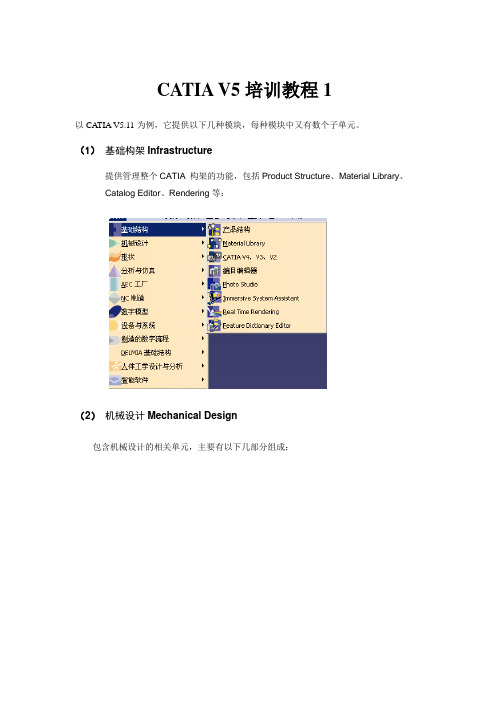
CATIA V5培训教程1以CATIA V5.11为例,它提供以下几种模块,每种模块中又有数个子单元。
(1)基础构架Infrastructure提供管理整个CATIA 构架的功能,包括Product Structure、Material Library、Catalog Editor、Rendering等:(2)机械设计Mechanical Design包含机械设计的相关单元,主要有以下几部分组成:(3)造型Shape提供曲面与逆向工程设计单元,可以自由塑造不规则曲面,利用手绘草图来构件曲面。
(4)分析与仿真Analysis & Simulation提供实体的网格划分(mesh)与静力、共振等有限元分析功能,并可输出网格分割数据共其它分析软件使用。
(5)APC 工厂布局提供工厂的规划建制功能。
(6)数控加工NC Manufacturing包含两轴到五轴加工的编程能力,并支持快速原型功能(STL Rapid Prototyping)。
(7)数字化仿真Digital Mockup包含动态机构仿真、装配配合空间分析、产品功能分析与功能优化等。
(8)设备与系统Equipment and Systems提供各种系统设备的建置,管路和电线的配置以及电子零件配置等功能。
(9)制造的数字化过程Digital Process for Manufacturing 提供在三维空间中进行产品的特征、公差与配合标注等功能。
(10)人体工学设计与分析Ergonomics Design&Anaysis提供人体模型,并可对产品进行人体空间分析。
(11)智能软件Knowledgeware一. 基本使用环境本章主要介绍CA TIA用户的基本操作界面、使用技巧、树结构(Tree)以及文件File、编辑Edit和视图View等菜单的操作等。
2.1 CATIA 的用户界面CATIA User Interface操作窗口菜单及工具条CA TIA对话框的组成2.2 操作技巧1. 鼠标的使用(1)使用三键鼠标,利用鼠标可以完成数种功能,包括选择和编辑对象、移动视角、右击打开弹出式菜单、旋转视角、物体的缩放等,具体使用如下:(2)选择和编辑对象:点击MB1(3)移动物体Translate:用MB2,按住中间不放,则物体随鼠标的移动而移动。
CATIA V5简介及基础应用技巧

CATIA V5 简介及基本应用
2、CATIA V5的模块总览
CATIA V5 简介及基本应用
CATIA V5 简介及基本应用
CATIA V5 简介及基本应用
CATIA V5 简介及基本应用
二、CATIA V5软件在使用前的设置
1、常用模块的添加 工具—自定义
CATIA V5 简介及基本应用
这样操作后,所有元素将作为一个整体。
Ps:在三维中写字,需要先在工程图中写好,选择好合适的字体,再另存为dxf文件,然后再打 开dxf文件,乊后的操作步骤不上述相同。
CATIAV5装配设计(AssemblyDesign)

CATIAV5装配设计(AssemblyDesign)CATIA V5 装配设计(Assembly Design)CATIA V5 装配设计(Assembly Design)是帮助设计师用自上而下或自下而上的方法定义和管理多层次的大型装结构。
3.1 相关的图像菜单3.1.1产品结构工具(Product Structure Toolbar)Inserting a New Component:将新元件插入一个已有的装配中,此子装配的名字不存盘Inserting a New Product:将新产品插入一个已有的装配中,此子装配的名字存盘Inserting a New Part:将新零件插入一个已有的装配中Inserting Existing Components:将存在的子装配插入一个已有的装配中Replacing Components:替换元件Reordering the Tree:在结构树上重新安排子装配的位置Generating Numbers:生成产品子装配的编号Product Initialization:产品初始化Unload Components :卸载子装配Load Components:加载子装配Isolate Part:孤立零件Deactivate Component:不激活子装配Activate Component:激活子装配Change Context:改变前后关系Fast Multi-Instantiation:快速多重引用Defining a Multi-Instantiation:定义多重引用Symmetry:镜像Manage Representations:管理产品的几何描述Design Mode:设计模式Visualization Mode:显示模式Deactivate a Node:不激活一个节点Activate a Node:激活一个节点Deactivate a Terminal Node:不激活一串节点Activate a Terminal Node:激活一串节点3.1.2 移动工具(Move Toolbar)Manipulating a Component:偏移或旋转子装配Snap Move:快速移动Smart Move:聪明移动Exploding an Assembly:爆炸图3.1.3 约束工具(Constraints Toolbar)Coincidence Constraint:同轴约束Contact Constraint:接触约束Offset Constraint:偏移约束Angle Constraint:角度约束Fixing a Component:固定一个子装配Fixing Components Together:子装配固定在一起Quick Constraint Command:快速约束命令Flexible Sub-Assemblies:柔性子装配Changing Constraints:改变约束Reuse Pattern:重复使用图样Deactivate Constraints:不激活约束Activate:激活约束3.1.4 更新工具(Update Toolbar)Update an Assembly:更新一个装配Update One Constraint Only:只更新约束3.1.5 约束创建模式工具(Constraint Creation Mode T oolbar) Default mode:默认模式Chain mode:链模式Stack mode:堆积模式3.1.6 注解工具(Annotations Toolbar)Text With Leader:带引出箭头的标注Flag Notes:超级链接3.1.7 装配特征工具(Assembly Features Toolbar)Assembly Split:装配切Assembly Hole:装配孔Assembly Pocket:装配凹坑Assembly Add:装配加Assembly Remove:装配减3.1.8 利用装配工具(Using Assembly Tools)Product Management:产品管理3.1.9分析工具(Analyze Tools)Bill of Material: 零件清单Analyze Updates:分析更新Analyze Constraints:分析约束Analyze Degrees of Freedom:分析自由度Analyze Dependences:分析依赖Compute Clash:计算干涉3.2 装配环境参数设定为了充分发挥CATIA V5的装配设计能力,必须根据设计对象的特点,合理地设定装配环境参数。
CATIAV5培训教程

CATIAV5培训教程一、引言随着科技的飞速发展,计算机辅助设计(CAD)软件在工业设计、建筑设计、航空航天、汽车制造等领域发挥着越来越重要的作用。
CATIAV5作为一款功能强大的CAD软件,已经成为全球众多企业和设计师的首选工具。
本教程旨在为初学者提供系统的CATIAV5培训,帮助读者快速掌握软件的基本操作和实用技巧。
二、CATIAV5简介1.CATIAV5概述CATIAV5是法国达索系统公司开发的一款CAD/CAE/CAM一体化软件,具有强大的三维建模、工程分析、制造仿真等功能。
自1982年问世以来,CATIAV5不断更新迭代,已经成为全球领先的CAD软件之一。
2.CATIAV5应用领域CATIAV5广泛应用于航空航天、汽车制造、造船、机械制造、建筑、消费品等领域。
通过使用CATIAV5,设计师可以更加高效地完成产品的设计、分析和制造。
三、CATIAV5基础操作1.界面布局CATIAV5的界面布局分为菜单栏、工具栏、工作区、命令提示栏和状态栏。
用户可以通过菜单栏访问软件的各项功能,通过工具栏快速执行常用命令,在工作区进行模型创建和编辑。
2.基本操作(1)新建文件:菜单栏“开始”→“机械设计”→“零件设计”,创建一个新的零件文件。
(2)选择对象:单击鼠标左键选择单个对象,拖动鼠标框选多个对象。
(3)移动、旋转、缩放:选中对象后,使用工具栏中的相应按钮进行移动、旋转和缩放操作。
(4)撤销和重做:工具栏中的撤销和重做按钮,可以撤销或恢复上一步操作。
3.视图操作(1)视图调整:通过工具栏中的视图控制按钮,可以切换正视、左视、俯视等视图。
(2)视图旋转:按住鼠标中键并拖动,可以自由旋转视图。
(3)视图缩放:滚动鼠标中键或按住Shift键并拖动鼠标中键,可以缩放视图。
四、CATIAV5功能模块1.零件设计零件设计是CATIAV5的核心模块,用户可以通过草图、拉伸、旋转、扫掠等命令创建三维模型。
2.曲面设计曲面设计模块提供了丰富的曲面创建和编辑工具,如放样、扫掠、填充等,可以创建复杂的曲面模型。
catiaV5双语菜单和使用手册

F3------隐藏目录树F1------实时帮助ctrl+z---------撤消ctrl+y--------redoctrl+n--------新建ctrl+o--------打开ctrl+鼠标中键视图放大缩小alt+鼠标中键视图平移alt+鼠标左键+鼠标中键视图旋转Alt + Enter = 性质shift 加中键出现红色方块后拖拉先按CTRL 再加中键是放大缩小先按中键再加CTRL 是是对象旋转而对象旋转时外面会出现红色的圆形区域在圆形区域内是XYZ轴的任意旋转而在圆形区域外是针对Z轴的特定旋转用鼠标指向某个封闭空心实体外表面,Ctrl + Page down ------zoom outAlt + shift + 上下左右箭头----rotateCtrl +上下左右箭头----panCtrl +shift + 左右箭头——————rotateshift+F3 --work on specification treeshiftecification tree overview (在工具拦)MB3+Customize.......可自定义在自F5--调出“操作平面对话框”(对“由N点成面”等命令尤为重要)控制金钱,可以得到财富;控制餐饮,可以得到健康;控制情绪,可以得到快乐;控制感情,可以得到幸Part Design装配设计ASD:Assembly Design交互式工程绘图IDR:Interactive Drafting创成式工程绘图GDR:Generative Drafting结构设计STD:Structure Design线架和曲面设计WSF:Wireframe and Surface钣金设计SMD:SheetMetal Design航空钣金设计ASL:Aerospace Sheetmetal Design钣金加工设计SHP:SheetMetal Production三维old Tooling Design阴阳模设计CCV:Core & Cavity Design焊接设计WDG:Weld Design自由风格曲面造型FSS:FreeStyle Shaper自由风格自由风格曲面造型FSP:FreeStyle Profiler基于草图的自由风格曲面造型FSK:FreeStyle Sketch Tracer创形设计GSD:Generative Shape Design创成式曲面优化GSO:Generative Shape Optimizer汽车E:Digitized Shape Editor汽车A级曲面造型ACA:Automotive Class A快速曲面重建QSR:Quick Surface Reconstruction配件结构分析GAS :Generative Assembly Structural Analysis变形装配件公差分析TAA:Tolerance Analysis of Deformable Assembly Elfini 结构分析EST:Elfini Solver Verification电路板设计CBD:Circuit Board Design电气系统功能定义EFD:Electrical System Functional Definition电气元件库管理员ELB:Electrical Library电气线束安装EHI:Electrical Harness Installation电气线束布线设计EWR:Electrical Wire Routing电气线束展平设计EHF:Electrical Harness Flattening管路和设理图设计PID:Piping & Instrumentation DiagramsHVAC 图表设计HVD:HVAC Diagrams电气连接原理图设计ELD:Electrical Connectivity Diagrams系统原理图设计SDI:Systems Diagrams管线原理图设计TUD:Tubing Diagrams波导设备原理图设计WVD:Waveguide Diagrams系统布线设计SRT:Systems Routing系统空间预留设计SSR:Systems Space Reservation电气缆线布线设计ECR:Electrical Cableway Routing设备布设计RCD:Raceway & Conduit Design波导设备设计WAV:Waveguide Design管路设计PIP:Piping Design管线设计TUB:Tubing DesignHVAC设计HVA:HVAC Design支架设计HGR:Hanger Design结构初步布置设计SPL:Structure Preliminary Layout结构功能设计SFD:Structure Functional Design设备支撑结构设计ESS:Equipment Support Structures厂房设计PLO Plant Layout数控加工查NCG:NC Manufacturing Review数控加工验证NVG:NC Manufacturing Verification2轴半加工准备助手PMA:Prismatic Machining Preparation Assistant 2轴半加工PMG:Prismatic Machining3轴曲面加工SMG:3 Axis Surface Machining多轴曲面加工MMG:Multi-Axis Surface Machining车削加工LMG:Lathe Machining高级加工AMG:Advanced Part MachiningSTL快速成型STL:STL Rapid Prototyping知识工顾问KWA:Knowledge Advisor知识工程专家KWE:Knowledge Expert产品工程优化PEO:Product Engineering Optimizer产品知识模板PKT:Product Knowledge Template业务BKT:Business Process Knowledge Template产品功能定义PFD:Product Function Definition产优化PFO:Product Function OptimizerDMU 漫游器DMN:DMNDMU NavigatorDMU 运动机构模拟KIN:DMU Kinematics SimulatorDMU 空间分析SPA:DMU Space AnalysisDMU装配模拟FIT:DMU Fitting SimulatorDMU优化器DMO:DMU OptimizerDMU工程分析审查ANR:DMU Engineering Analysis Review DMU程助手SPE:DMU Space Engineering Assistant人体模型构造器HBR:Human Builder人体模型测量编辑HME:Human Measurements Editor人体姿态析HPA:Human Posture Analysis人体行为分析HAA:Human Activity Analysis。
CATIA V5经典练习题1-GSD_Mobil_Phone_V5

CATIA Training COPYRIGHT DASSAULT SYSTEMES 2002Version 5 Release 10December 2002G e n e r a t i v e S h a p eDe s i g n D e t a i l e d S t e p sTable of ContentsMobile Phone (3)Step 1: Creating the Wireframe Geometry (3)Step 2: Creating the Surfaces (8)Step 3: Performing operations (15)Step 4: Analyzing and Modifying (25)Step 5: Completing the part in Part Design (33)Mobile PhoneStep 1: Creating the Wireframe GeometryLoad the part called CATGSD_F_Phone_Step1_start.CATPartfrom the ''Companion'' and save the part in the Students directory.1. You are going to extract the elements that will be necessary to complete the wireframe geometry:▪Double-click on the Extract icon▪Select the elements to be extracted (two pink edges and the yellow face) :▪Click Cancel to close the Extract dialog box.2. You are going to use these extracted elements to create the wireframe geometry:▪Click on the Parallel Curve icon .▪Select the shortest pink extracted curve as element to offset, and the yellow face as support:▪Click OK to confirm.▪Click on the point creation icon .▪Select the “on curve” type and the previous parallel curve as support. Create this point:▪Click on the Parallel Curve icon .▪Select the second pink extracted curve as element to offset, and the yellow face as support:▪Click on the Parallel Curve icon .▪Select the first pink extracted curve as element to offset and the yellow face as support:▪Click on the Connect Curve icon .▪Create this connect curve:▪Click on the project icon and project the previous connect curve to the yellow extracted face:▪Click on the corner icon and create a corner between the these two curves (the shortest parallel curve and the projected curve):▪Click on the point icon and create a point on the YZ plane using these parameters:▪Click on the circle icon and create a circle using the previous point as center, YZ plane as support and the following parameters:Step 2: Creating the SurfacesLoad the part called CATGSD_F_Phone_Step2_start.CATPart from the ''Companion'' and save the part in the Students directory.1. Insert a new open body:2. Rename it “Surfaces”:▪Click with the third mouse button on the new created open body and select “Properties”:3. You are going to create the two points that will be used to create the sweep sections:▪Double-click on the Point icon.▪Select the point type “on curve” and create these two points on the corner curve:▪Click Cancel to close the Point dialog box.4. You are going to create the adaptative sweep using the corner curve, these two points and the extracted face:▪Click on the Adaptative sweep icon.▪Select the corner curve as guiding curve:▪Now you are going to create the section:▪Right click in the sketch field and select “Create sketch”:▪This dialog box appears:▪Select this point:▪The dialog box becomes:▪Click OK to confirm. You automatically access the sketch creation. ▪Create this sketch:▪Create these constraints (be careful to place them correctly):▪Exit the sketch by clicking on this icon.▪Select the points that will define the sectionsSelect this point to define the second section:Select this point to define the third section:Select this vertex to define the last section:You are going to change the 3rd and 4th sections parameters:▪Click OK to confirm the adaptative sweep creation:5. You are going to create a linear sweep using the circle as guiding curve:▪Click on the sweep icon .▪Choose the linear sweep type and the sub-type “with reference surface”▪Choose the circle as guide curve and the YZ plane as reference surface:▪Key in these parameters:▪Click OK to confirm the sweep creation:6. You are going to create a fill surface using the upper boundary of the previously created surface:▪Click the fill surface icon .▪Select the upper boundary of the linear sweep:▪Click OK to confirm the fill surface creation:Step 3: Performing operationsLoad the part called CATGSD_F_Phone_Step3_start.CATPart from the ''Companion'' and save the part in the Students directory.1. Insert a new open body:2. Rename it “operations”:Click with the third mouse button on the new created open body and select “Properties”:3. You are going to join the linear sweep with the fill surface and split the resulting join with the datum blue surface:▪Click on the Join icon .▪Select the linear sweep and the fill surface and confirm the join creation clicking OK:4. You are going to split the datum blue surface with the ZX plane:▪Click on the Split icon.▪Select the blue datum surface and the ZX plane:▪Click on the “Other side” buttons in order to keep the correct part of split surface. Click OK to confirm the operation.5. You are going to add an edge on the previously created surface:▪Click on the edge fillet icon.▪Select this edge to be filleted and key in a 3mm radius value:6. You are going to create a multi edge fillet on the previous surface:▪Click on the edge fillet icon.▪Select this first edge:▪The edge fillet dialog box appears. Key in a 1mm radius value in the dialog box:▪Select these other edges:▪Now 10 edges are included in the edge fillet:▪You are going to use the “Blend corner” option: expand the dialog box clicking on “More”:▪Click on the “Blend corner(s)” button. CATIA detects 4 corners:▪Key in a 3mm setback distance:▪Click OK to confirm the edge fillet creation:6. You are going to Trim the previous edge fillet surface with the Adaptative sweep:▪Click on the Trim icon .▪Select the previous fillet surface and the Adaptative sweep:▪Click on the “Other side” button until you get this configuration.▪Click OK to confirm the trim creation:7. You are going to create the last edge fillet on the previous trim surface:▪Click on the edge fillet icon.▪Select these two edges:▪Key in a 0.2mm radius in the edge fillet dialog box:▪Click OK to confirm the edge fillet creation:8. You are going to create the symmetric surface of the previous fillet surface:▪Click on the symmetry icon:▪Select the previous edge fillet surface and the ZX plane as reference plane:▪Click OK to create the symmetric surface.9. You are going to join these 2 surfaces:▪Click on the join icon.▪Select the last edge fillet surface and the symmetry surface:▪Click OK to confirm the join creation.10. You are going to split the antenna with the previous join surface:▪Click on the split icon:▪Select the antenna as surface to split and the previous join as cutting element:Click OK to confirm the split creation:Step 4: Analyzing and ModifyingLoad the part called CATGSD_F_Phone_Step4_start.CATPart from the ''Companion'' and save the part in the Students directory.1. Insert a new open body:2. Rename it “Analysis”:Click with the third mouse button on the new created open body and select “Properties”:3. You are going to create a reflect line on the main surface :▪Click on the Reflect Line icon.▪Select the main surface as support and the Z axis as direction :▪Key in the angle: 90deg.▪CATIA asks you if you want to keep only one sub-element of the generated reflect line: click YES▪And select the point (0,0,0: origin) as reference element to create the near element:▪Click OK to confirm the near element creation :4. You are going to use this near element to split the surface:▪Click on the Split icon.▪Select the surface as element to cut and the near element as cutting element:Note: switch on the option “Keep both side”.▪Rename the two created split surface “Top” and “Bottom”:▪Hide the top surface:5. You are going to Perform a draft analysis on the bottom surface (you have first to get to the material view mode):▪Click on the Draft Analysis icon.▪Select the bottom surface and set the analysis settings to this:▪There is no red area on the surface: you can hide it and show the top surface:6. You are going to perform a draft analysis on the top surface:▪Click on the draft analysis icon.▪Select the bottom surface and set the analysis settings to this:▪Invert the analysis direction:7. You are going to modify the shape to correct this anomaly:▪Double click on the Ad aptative sweep in the “Surface” pen Body:▪The Adaptative sweep dialogue box is displayed. Click on “UserSection.1”:▪Modify this parameter’s value (angle):▪Click OK to confirm the adaptative sweep modification. The whole part is automatically updated.▪Join the surfaces “Top” and “Bottom”.Step 5: Completing the part in Part DesignLoad the part called CATGSD_F_Phone_Step5_start.CATPart from the ''Companion'' and save the part in the Students directory.1. Access the Part Body:2. You are going to create a solid from the join surface:▪Click on the Thick Surface icon .▪Select the join surface and key in these parameters:▪Click OK to confirm the thick surface creation.3. You are going to Sew the antenna surface to the main solid:▪In the “Operation” Open Body, show the split antenna:▪Click on the sew icon .▪Select the split antenna and orientate the arrows this way (inside the antenna):▪Click OK to confirm the sew creation:。
K清风CATIAV520问题解答
CATIA-V5-20问题解答Catia 网络资料收集2006-12-101.双曲面展开问题大家对CATIA里〔R17版的〕新增曲面展开功能什么看法阿?我觉得展开后跟实际差的很多? A.其实展开本身就有误差,1、从微积分的角度上讲,展开是把整个曲面进行微小的划分,对每个单元格的面积进行计算,然后再进行整合,得出展开后的图形。
2、从材料的自身性能上讲,每种材料都有自己的塑性变形量,而且在不同的情况下变形量也不一样,而且展开属于一种逆向的过程,这种变形量的误差也存在其中。
曲面形状越曲率,展开误差就越大。
曲面形状越平坦,展开误差就越小。
一般来说,展开曲面都是对直纹面进行展开。
其它的都有材料的拉伸和压缩。
简单例子,现在的世界地图都是变形的。
不可能真正的展开2.翻开文件时,不能预览。
如题。
刚装上CATIA的时候可以的,不知何时就不能拉。
图片附件: (2006-12-13 14:22, 49.91 K)同样在文件夹里查看--缩略图,也显示不出来。
什么原因啊?图片附件: (2006-12-13 14:25, 50.16 K)答案:在dos窗口中进入bin的目录,输入指令:CNEXT.exe /regsvr32這也不行,你不是刪了低版本的CATIA導致的?**好象是这样的,卸载了R14。
**好象DS中的说明是这样的CNEXT.exe /regserver参数/regsvr32 可能会不好,菜鸟之见,莫笑!而为了保险起见,先输入CNEXT.exe /unregserver以去掉R14的影响,再来个CNEXT.exe /regserver当然电脑要REBOOT才会见效,依旧是菜鸟之见,各位CATIA的大侠莫笑!**我找了一下以前保存的资料也是:CNEXT.exe /regserver。
没有32,LZ再试试3.替换命令用法简介1,曲面替换实体外表图片附件: (2005-11-15 20:11, 15.21 K)2,主意选择,及箭头方向图片附件: (2005-11-15 20:13, 32.32 K)3,结果如下。
CATIAV5将知识工程应用于汽车零部件开发
基于知识工程的CATIA V5可以实现产品定义过程的自动操作,利用企业现有标准加快确定设 计方案,帮助设计人员在最短的时间内做出正确的决策并实现零错误的最佳设计和提高产品质量。
本文以汽车零部件开发为例,深入介绍了CATIA V5知识工程功能的应用。
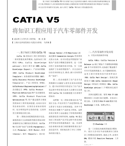
CATIA V5将知识工程应用于汽车零部件开发【 武汉理工大学汽车工程学院 熊 欣 】 【 上海江达科技发展公司武汉办事处 马洪阁 】二、汽车零部件开发应用1. 开发应用的软件环境一、基于知识工程的CATIA V5CATIA V5 的知识工程主要体现为 一系列智能化软件模块,包括知识工程 顾问(K W A ,C A T I A K n o w l e d g e Advisor )、知识工程专家(KWE ,CATIA Knowledge Expert )、产品知识模板(PKT ,CATIA Produ ct Knowl edge Template )、业务流程知识模板(BKT , CATIA Business Process KnowledgeT e m p l a t e )、产品工程优化(P E O , CATIA Product Engineering Optimizer )、 产品功能定义(PFD ,CATIA Product Function Definition )和产品功能优化(PFO ,CA TIA Pr od uct F u nc ti on Optimization )等。
用户通过提供方便易用的知识工程环境来创建、访问以及应 用企业知识库,在保存企业知识的同 时,充分利用这些宝贵的经验。
它的作 用主要体现在两方面。
第一,帮助企业把规范的设计信息、 最优的设计方法和流程等隐含的知识轻 易地转化为正规的显式的知识。
CA TIA V5可以将“知识”以参数(Parameters )、 公式(Formulas )、规则(Rules )、检查 (Checks )、报告(Reports )、设计表(Design Tables )、应变(Reactions )、创成式脚本(Generative Scripts )等多种形 式表示出来,还可以把这些智能资产封 装为产品设计模板直接使用。
2024版年度CATIAV5介绍与应用

Assembly analysis: Evaluate the performance of assemblies, including motion simulation and collection detection
2024/2/2
Interaction checking: Identify and resolve potential claims or overlaps between components in an assembly
• Advanced Simulation and Analysis: CATIAV5 provides advanced simulation and analysis capabilities that enable engineers to test and validate designs before manufacturing, saving time and costs
Global Adoption and Impact
Today, CATIAV5 is widely used across various industries such as automotive, aerospace, shipbuilding, and more It has significantly transformed the way products are designed, developed, and manufactured
CATIA_V5结构分析教程_Structural_Analysis_for_the_Designer

2
CAT509, Workshop 14, March 2002
WS14-9
Step 3. Create knowledge rule
2
The Knowledge Advisor workbench should now be active . Steps: 1. Click the Rule icon from the Knowledge Advisor workbench. 2. Key “Displacement Max” as the name of the rule. 3. Key in a description for the rule or accept the default. 4. The rule will be saved under the Relations category – do not modify. 5. Click OK. 6. Rule Editor window displays the active rule (Displacement Max).
Default Energy sensor 1
“dispmax” sensor
2 “misesmax” sensor
The Energy sensor is automatically created with every analysis document. It measures global strain energy of the structure.
1st line: Rule description 1 2 3
Define the rule.
Steps:
1. Click to place the cursor at the end of the 1st line and then hit the Enter key to start a new line. 2. Select Keywords in the Dictionary window. 3. Double-click on “if” to begin the line. 4. Single-click the Max Displacement sensor in the tree to list its parameters in the Members of All area. 5. Double-click on „Maximum displacement Value‟ to add it to the definition.
CATIAV5常用的模块简介
CATIA V5常用模块简介CATIA V5零件设计(PDG:CATIA Part Design)提供了3D机械零件设计的强大的设计工具。
应用“智能实体”设计思想,广泛使用混合建模、关联特征和灵活的布尔运算相结合的方法,允许设计者灵活使用多种设计手法:可以在设计过程中或设计完成以后,进行参数化处理;可以在可控制关联性的装配环境下进行草图设计和零件设计,在局部3D参数化环境下添加设计约束;由于支持零件的多实体操作,还可以轻松管理零件更改,如进行灵活的设计后期修改操作。
此外,PDG图形化的结构树可表示出模型特征的组织层次结构,以便更清晰地了解影响设计更改的因素。
设计人员可以对整个特征组进行管理操作,以加快设计更改。
CATIA V5装配设计(ASD:CATIA Assembly Design)可以帮助设计师用自顶向下(Top-down)或自底向上(Bottom-up)的方法定义和管理多层次的大型装配结构,可真正实现装配设计和单个零件设计之间的并行工程。
通过简单地移动鼠标或选取图标,设计人员就能将零件拖动到或快速移动到指定的装配位置;选择各种形式的机械约束,用来调整零件的位置并建立起约束关系;选择手动或自动的方式进行更新,可以重新排列产品的结构,并进行干涉和缝隙检查;无需复制相同零件或子装配数据,就可以在同一个装配件或不同装配件中重复使用。
ASD建立标准零件或装配件的目录库,爆炸图的自动生成使用对设计的理解非常容易,分析功能可检查是否发生干涉以及是否超过了定义的间隙限制。
无论多么复杂的装配,BOM(Bill of Material)表自动生成功能可得到所有零部件的准确信息。
柔性子装配功能可以动态地切断产品结构和机械行为之间的联系,这一独特的命令能够在父装配中移动子装配的单独部件,或者管理实例化子部件不同的内部位置……ASD提供的这些高效的工作方式,使得装配设计者可以大幅减少设计时间和提高设计质量。
CATIA V5创成式曲面设计(GSD:CATIA Generative Shape Design)可根据基础线架与多个曲面特征组合,设计复杂的满足要求的轿车车身。
CATIA-V5-装配设计课件

在CATIA V5中有两种显示模式: 设计模式(Design Mode):此模式下显示组件的完整几何数据。 纯图标模式(Visualization Mode):此模式下工作台只显示几何体的CGR格式影像文件,显示在特 征树上就是没有加号的图标。前提是在高速缓存系统中有此组件的CGR文件存在。组件的几何数据 需另个引入。在组件甚多、数量很大的情况下采用此模式可以大大加快系统的读取速度。高速缓存 系统采用的就是纯图标模式,即轻量化模式。 Cache Management 选项卡:
入到当前装配的产品中。
在对话框仍打开时,通过Apply(应用) 按扭可多次执行此命令。
(2)快束多实例化(Fast Multi Instantiation) 如果“定义单行阵列”命令中各参数已设置好,并且在Multi Instantiation对话框中选中了 Define As Default复选框,则定义单行阵列中定义的参数可以在快束多实例化(Fast Multi Instantiation)命令中重复使用。
在此状态设置下,打开一个装配文件,目录树上都呈卸载状态,单击该命令图标弹出Product
Load Management 对话框,在目录树上选择要加载的组件,单击对话框中的
按钮加载
CATIA V5 Training
9、管理表达(Manage Representations) 此命令的功能是对当前装配产品中的组件进行显示的管理与修改、替换。
3、插入现有组件(Existing Component) 此命令用于在产品或组件中插入已存在的零、组件。 如果插入到装配中的零件、产品、模型或.cgr文件与装配中包含的零件、产品或模型或.cgr文件
CATIA V5 模块介绍及模块配置表格
CATIA产品介绍机械设计产品MD1MD2CATIA装配设计1(AS1) CATIA装配设计2(ASD) P1与P2机械设计产品 CATIA 装配设计产品,可以实现自上而下或自下而上的装配和零件设计。
设计师点击产品结构树,即可实现零件设计和装配设计之间的切换,并可实现3D机械零件和装配件的关联设计。
通过简单地移动鼠标或选取图标,用户就能将零件拖动到或快速移动到装配位置。
在装配件中可快速进展干预的检查。
CATIA零件设计1(PD1)CATIA零件设计2(PDG) P1与P2机械设计产品具有零件3D实体设计的强大功能。
该产品同时还具有关联的基于特征功能和动态草图设计。
采用后参数化处理技术,用户可以进展模糊化设计,并在设计的任何阶段进展参数化修改。
图形化的造型特征树清晰反映整个设计流程,用户可以对整个特征组进展管理操作,以加快设计更改。
CATIA线架和曲面造型1(WS1)CATIA线架和曲面造型2(WSF) P1与P2机械设计产品具有强大的曲面、线框类元素生成能力,作为CATIA零件实体设计能力的补充。
可以进展复杂的零件外型设计,是实现混合建模的重要手段,丰富了CATIA 的实体造型能力。
CATIA创成式工程绘图1(GD1)CATIA创成式工程绘图2(GDR)P1与P2机械设计产品可以3D机械零件和装配中生成相关联的二维工程图。
同时可以自动生成3D尺寸标注。
可以快速生成相关的剖视图、局部放大视图、向视图等相关视图。
可以进展标准的信息标注和注释。
3D模型与二维图纸的关联性保证了设计更改的一致性。
同时还提供有可以输出DXF、DWG等常用的二维数据格式。
CATIA交互式工程绘图1(lD1) P1与P2机械设计产品提供高效的交互式绘图工具进展产品的2D设计。
其集成化的2D交互功能和高效的制图和注释功能进一步丰富了CATIA创成式工程绘图。
它将使用户能够平稳、顺畅从2D 设计过度到3D设计。
CATIA3D公差定义与标注1(FT1)CATIA3D公差定义与标注2(FTA )P1与P2机械设计产品该产品是实现纯数字化无图纸制造的重要工具。
CATIA V5主要模块中英文对照表
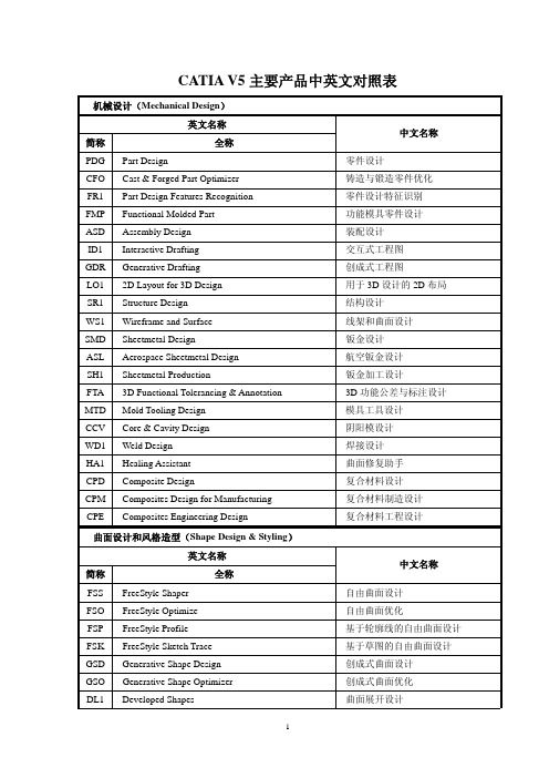
中文名称
零件设计 铸造与锻造零件优化 零件设计特征识别 功能模具零件设计 装配设计 交互式工程图 创成式工程图 用于 3D 设计的 2D 布局 结构设计 线架和曲面设计 钣金设计 航空钣金设计 钣金加工设计 3D 功能公差与标注设计 模具工具设计 阴阳模设计 焊接设计 曲面修复助手 复合材料设计 复合材料制造设计 复合材料工程设计
EHF Electrical Harness Flattening
EC1 PID HVD ELD
Electrical 3D Design & Documentation Piping & Instrumentation Diagrams HVAC ② Diagrams Electrical Connectivity Diagrams
WAV PIP
Waveguide Design Piping Design
TUB Tubing Design
HVD HVAC Design
HGR Hanger Design
CNA SPL
Compartment & Access Structure Preliminary Layout
SFD SDD ESS
2
简称
英文名称 全称
CBD Circuit Board Design
EFD Electrical System Functional Definition ELB Electrical Library
EHI Electrical Harness Installation
EWR Electrical Wire Routing
IMA Imagine & Shape
DSE Digitized Shape Editor