AMS2500安装手册
AMS 客户端操作手册说明书

AMS客户端操作手册安装使用前请仔细阅读操作手册目录1AMS客户端软件介绍 (4)2AMS客户端软件连接方法 (5)2.1直连模式 (5)2.2网络连接模式 (5)3AMS客户端软件安装与卸载 (7)3.1软件安装 (7)3.2软件卸载 (9)4AMS客户端软件登录 (12)5AMS客户端设备管理 (13)5.1添加设备 (13)5.1.1搜索添加设备 (13)5.1.2手动添加设备 (15)5.2修改设备信息 (16)5.3删除设备 (16)5.3.1单个删除 (16)5.3.2批量删除 (17)5.4设备列表重置顺序 (17)5.5本地与P2P设备 (18)6AMS客户端预览 (20)6.1界面简介 (20)6.2实时预览 (21)6.2.1开启预览 (21)6.2.2预览操作 (22)6.2.3调整监视窗口数 (23)6.3云台设置 (23)6.3.1设置预置位 (24)6.3.2设置巡航 (25)7回放 (26)-1-7.1录像回放 (26)7.2回放设备录像 (28)7.3回放本地录像 (29)8云平台登录 (31)9云平台预览 (33)9.1云平台界面简介 (33)9.2云平台实时预览 (34)9.2.1开启云设备预览 (34)9.2.2云平台预览操作 (35)9.2.3调整监视窗口数 (36)9.3云平台设备云台设置 (36)10云平台回放 (37)10.1录像回放 (37)10.2回放云服务录像 (39)10.3回放本地录像 (40)11日志查询 (41)11.1查询系统日志 (41)11.2查询报警日志 (42)11.3查询智能报警日志 (43)12事件 (45)12.1查询报警事件 (45)12.2查询智能报警事件 (46)12.3报警联动本机录像 (47)13抓拍 (49)13.1抓拍图像 (49)13.2抓图预览 (49)14录像下载 (52)14.1查询录像 (52)14.2下载录像 (53)15云录像下载 (55)-2-15.1查询云录像 (55)15.2下载云录像 (56)16设备配置 (58)17用户配置 (62)17.1用户管理 (62)17.2用户参数 (63)18系统设置 (65)18.1基本设置 (65)18.2磁盘设置 (65)18.3关于 (66)18.4切换用户 (66)18.5操作手册 (66)18.6退出系统 (66)-3-1AMS客户端软件介绍AMS客户端软件是一款功能完整的网络监控管理软件,它支持网络摄像机、网络球机、NVR设备接入。
AMS2500安装手册
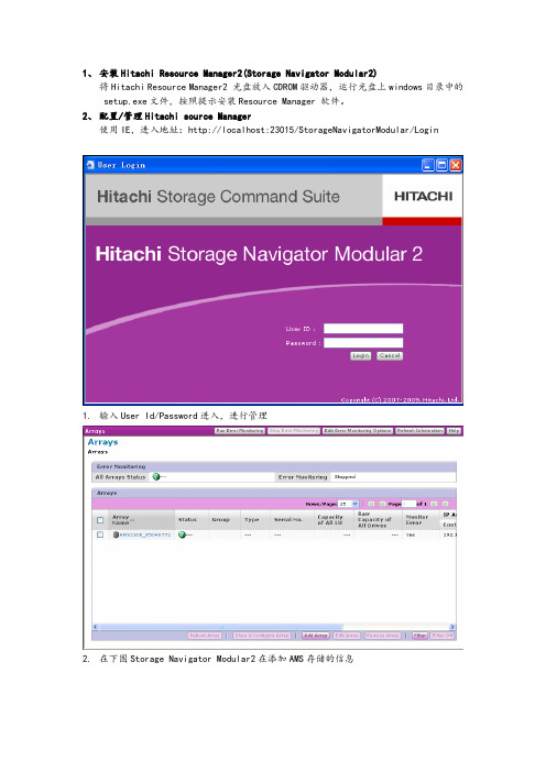
1、安装Hitachi Resource Manager2(Storage Navigator Modular2)将Hitachi Resource Manager2 光盘放入CDROM驱动器,运行光盘上windows目录中的setup.exe文件,按照提示安装Resource Manager 软件。
2、配置/管理Hitachi source Manager使用IE,进入地址:http://localhost:23015/StorageNavigatorModular/Login1.输入User Id/Password进入,进行管理2.在下图Storage Navigator Modular2在添加AMS存储的信息3.进入设备的初期信息修改向导4.设置E-mail提醒(如果不用,请设为Disable):5.修改管理端口的IP地址:6.修改前端端口属性(连接交换机要改为P2P,直联使用Loop):7.修改系统时间:8.各项确认:9. 添加完毕后出现的管理窗口如下:10.设置Spare盘11.创建Raid组12.创建Lun13.打开Host Group Security参数14.添加HostGrop15.创建主机WWN映射16.映射Lun17.修改主机平台说明:Lenovo-HDS AMS2000系列实施指南V1.2●:参数被Simple Setting自动选择。
空白:如果需要参数可以手动选择。
Not specified:不指定。
3、注释:使用SNM2指定Platform (操作系统)和 Middleware(cluster软件)。
剩下的参数基于 Platform (操作系统)和 Middleware(cluster软件)指定的组合选项,被系统自动设置。
在使用iSCSI连结阵列时,如果使用emBoot winBoot/i 或Novell Open Enterprise Server,确认Detail Setting中的“NOP-In Suppress Mode”选项被激活。
AMS2000安装配置手册
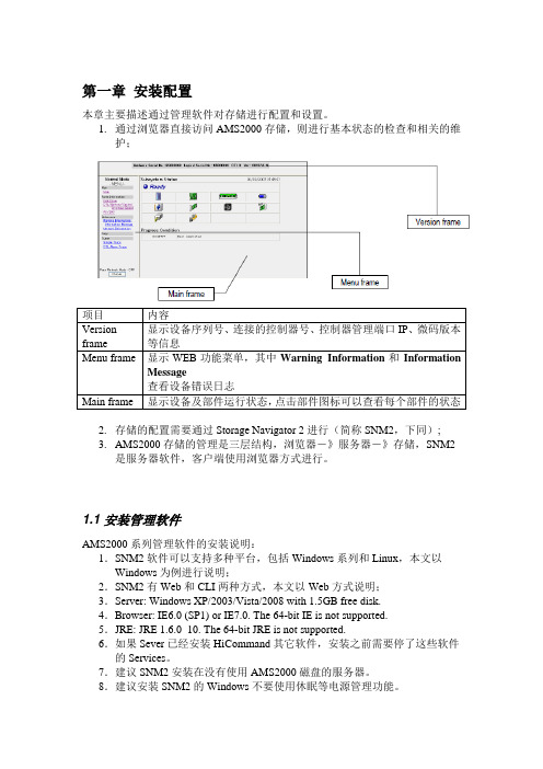
第一章安装配置本章主要描述通过管理软件对存储进行配置和设置。
1.通过浏览器直接访问AMS2000存储,则进行基本状态的检查和相关的维护;2.存储的配置需要通过Storage Navigator 2进行(简称SNM2,下同);3.AMS2000存储的管理是三层结构,浏览器-》服务器-》存储,SNM2是服务器软件,客户端使用浏览器方式进行。
1.1 安装管理软件AMS2000系列管理软件的安装说明:1.SNM2软件可以支持多种平台,包括Windows系列和Linux,本文以Windows为例进行说明;2.SNM2有Web和CLI两种方式,本文以Web方式说明;3.Server: Windows XP/2003/Vista/2008 with 1.5GB free disk.4.Browser: IE6.0 (SP1) or IE7.0. The 64-bit IE is not supported.5.JRE: JRE 1.6.0_10. The 64-bit JRE is not supported.6.如果Sever已经安装HiCommand其它软件,安装之前需要停了这些软件的Services。
7.建议SNM2安装在没有使用AMS2000磁盘的服务器。
8.建议安装SNM2的Windows不要使用休眠等电源管理功能。
9.可以实施Update安装,相同版本的Update安装视作Uninstall。
10.安装时,需要输入SNM2的IP,不要输入127.0.0.1或localhost1.1.1 安装过程安装过程按照画面提示进行输入相关信息;注意一定要输入你的笔记本(或者服务器)的固定IP地址,该IP地址必须能与存储进行互通的(同一个网段是好主意)1.1.2 SNM2服务器端服务的操作•建议不要使用Windows的图形界面启动或停止SNM2的Services•c:\Program Files\HiCommand\Base\bin\hcmdssrv.exe /startKAPM06440-I The HiRDB service has already StartedKAPM05007-I Already started service. Service-name HBase Storage Mgmt Web serviceKAPM05007-I Already started service. service-name =HBase Storage MgmtCommon service.•c:\Program Files\HiCommand\Base\bin\hcmdssrv.exe /stopKAPM05017-I Succeeded in stopping of service. Service -name =HBase storage mgmt common service.KAPM05017-I Succeeded in stopping of service. Service -name=HBase storage mgmt web service.KAPM06441-I The HiRDB services has already stopped1.1.3 客户端Java需求:•JRE 1.6.0_10 or newer不需要设置•less than 1.6.0_10–Start◊Settings◊Control Panel.–From the Control Panel, select the Java.–Click View of the upper position in the Java tab.–Enter “-Xmx192m”–(“-Xmx216m” when the Hitachi Storage Navigator Modular 2 is version 7.00 or later)1.2 启动界面http://<IP address>:23015/StorageNavigatorModular/登陆用户名/密码:1.3 注册存储SNM2软件初次使用时尚无存储进行管理,软件会自动提示注册存储;如果SNM2原来已经有存储在使用,则点击Add Array,弹出以下画面,执行四个流程:Introduction Screen > Search Array Screen > Add Array Screen> Finish ScreenIntroduction Screen解释SNM2注册存储的说明。
AMS安装配置

p6
All Rights Reserved © Alcatel-Lucent 2008
AMS安装(续二) 正常AMS启动后结果实例
p7
All Rights Reserved © Alcatel-Lucent 2008
plugin卸载 去激活plugin,如: /var/opt/ams/local/repository/plugin-idm-isam-4.3-1.0_2.0.10_9.0.10131474/bin/deactivate.sh 卸载plugin,如: /var/opt/ams/local/repository/plugin-idm-isam-4.3-1.0_2.0.10_9.0.10131474/bin/uninstall.sh plugin卸载实例
p20
All Rights Reserved © Alcatel-Lucent 2008
AMS配置操作——idm采集设置(续2) EPON针对NBI采集必选项 请参考右表
Ne Family EPON Object Name MediaGateway Attribute Name IP Address(General-Primary Gateway Controller) Media
p19
All Rights Reserved © Alcatel-Lucent 2008
AMS配置操作——idm采集设置(续) 设置网元系列(GPON、EPON、FX则为ISAM),对于需要采集的项目,勾选对应 的“已采集”项;对于需要在界面中显示的,勾选对应的“已索引”项;点击右 上角蓝色勾号完成设定
AMS配置操作——AMS登录 AMS登录 输入IP、用户名和密码 管理员账户admin,默认密码admin,第一次登陆后会提示修改密码
日立 AMS 2500产品技术说明书
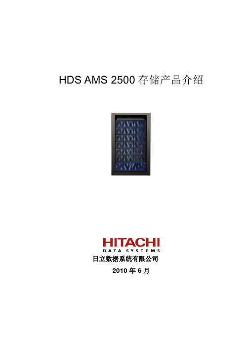
“划时代”的创新技术
采用特有的Active-ActiveSymmetric的对称均衡控制器架构,实现了以往高端存储才具有的前后端访问的自动负载均衡,克服了原有双控制器“各自为战”的中端存储割裂式访问瓶颈
早在1997年,利用开放性上的优势,FC-AL得到了众多厂商的拥护,但对于磁盘阵列内部的存储互连来说,硬盘驱动器的所谓“FC”,其实是FC-AL(Fibre Channel Arbitrated Loop,光纤通道仲裁环路),经铜缆(机箱之间才是光纤)连接成一个环路,一个仲裁环理论上可以连接127个设备,但受制于带宽,容纳的磁盘驱动器通常不到这个数字的一半。因此,存储行业的几家领先厂商带头开始研发被称为Serial Attached SCSI(串行连接SCSI,即SAS)的技术,作为并行SCSI的接班人。SAS与FC光纤通道相比,最明显的技术优势在于连接带宽:
采用特有的Active-ActiveSymmetric的对称均衡控制器架构,实现了以往高端存储才具有的前后端访问的自动负载均衡
提供先进的缓存分区功能,面向应用系统优化存储环境
基于前端FC的点到点、后端SAS的点到点的高性能体系架构
高安全性—99.999%的高可用性,没有单点故障;冗余的、可热插拔的组件
2.2
AMS2000存储系统进行了创新性的设计,彻底改变了原有中端磁盘阵列在双控制器上割裂式的访问带来的弊端,在AMS2000以前的所有中端存储产品都存在这样的问题:
所有存储里可用的LU都必须手工分配主控制器和Ownership,另一个控制器对这个LU只能“袖手旁观”,只有主控制器故障时起到备份作用。这一方面难以做到真正的负载均衡,另一方面在主控制器故障切换到备份控制器时有访问的中断,至少几秒到几十秒,很可能导致数据库和系统的宕机;
Acterna DSAM-2500产品说明书

19812The results focused meter Simplified installationDOCSIS cable modem installation is simplified for even the novice installer. Not just one, but multiple downstream DOCSIS carriers can be tested in a single, automated cable modem test. Immediate Pass/Fail message is dis-played. Details of failed parameter(s) are noted in the autotest results.Fast ingress identificationChecking the install for ingress is easy with a before and after approach that uses the DSAM upstream spectrum display. Unwanted carriers can be quickly located and measured (center frequency, level and graphical view). Interference from intermittent sources can be captured with the peak hold feature. For the greatest amount of detail a 10MHz zoom can be used at the marker position.The cable modem autotest function provides an immediate Pass/Fail message The DSAM upstream spectrum display makesidentifying ingress quick and easy3Rapid synchronizationExchanging files with a PC is as simple as synchronizing a PDA with a desktop computer with the optional DSAM-PC utility software. An administrator can easily set up a procedure where the individual meters are just plugged into the PC via RS232 or Ethernet. Ethernet connectionscanbeconductedremotely on the same local area network.Swift settings reproductionMeter settings may be exchanged directly with another meter through the cloning capability. All settings, or selected groups of configuration With limits “on”, key digital and analog channels are quickly checked in miniscan view Single channel level view displays all modulation types in a common format for all usersSynchronizing the meter with the optional DSAM PC software is an easy operation understood by all usersThe cloning function allows specific configuration groups to be exchanged with another meterThe DSAM’s file management system allows users to save, label and organize information as neededComprehensive SLM capabilities The DSAM’s SLM capabilities handle all of the traditional needs of the cable installer. The meter not only provides a single-channel level display, it also delivers a 12-channel miniscan ensuring the fastest evaluation oflevels at an install. As with all measure-ments and autotests, limits can be turned on to quickly indicate Pass or Fail. Limits are preconfigured for four test locations: tap, ground block, TV and cable modem. These may be configured and locked by installmanagement or network engineering to ensure maximum test reliability Channel plan integration of digital QAM channels with analog channels provides a common, easily understood, user interface for installers4Specifications (preliminary)FrequencyRange 4 to 1,000 MHz Accuracy±10 ppm at 77°F (25°C) Tuning resolution Analog 10 KHzDigital 50 KHz Channel bandwidth DSAM-2500A 8 MHzDSAM-2500B 6 MHz Level measurement, analogSignal types CW, video and audio(NTSC, PAL, and SECAM) Range–40 to +60 dBmV(1) Resolution0.1 dB Resolution bandwidth 330 KHz Accuracy(2)±1.5 dB typical @ 25°C Level measurement, digitalModulation types QPR, QPSK, QAM (DVB/ACTS) Range–40 to +60 dBmV(1) Resolution0.1 dB Resolution bandwidth330 kHz Accuracy(2)±2.0 dB typical @ 25°C Upstream spectrum (ingress scan)Spans DSAM-2500A 4 to 65 MHzDSAM-2500B 4 to 45 MHz Sweep rate 1.8 seconds or faster Display scaling and range5 and 10 dB/division;6 vertical divisions Resolution bandwidth330 kHz Sensitivity –35 to 60 dBmV(1) DOCSIS/EuroDOCSIS compatibilityVersion DOCSIS 1.0 and 1.1 Upstream transmit range and diplexer crossover (DOCSIS modes only)DSAM-2500A 5 to 65 MHz 65/96MHz(min. downstream DOCSIScenter freq. 100 MHz)DSAM-2500B 5 to 42 MHz 42/88 MHz(min. downstream DOCSIScenter freq. 91 MHz) Upstream modulation QPSK and 16 QAM asinstructed by CMTS Transmitter output At 25ºC, maximum 55 dBmVwith 16 QAM and 58 dBmVwith QPSK, (typical)Downstream QAM demodulationModulation type 64 and 256 QAM, ITU-T J.83Annex A, B or C (selectable)Input range (lock range) –15 to +50 dBmV totalintegrated power(3)from 55 to 1000 MHzBER(4)Pre- and Post-FEC 10-4to 10-9MER(4)Range 64 QAM: 21 to 35 dBAccuracy ±2 dB (typical)Range 256 QAM: 28 to 35 dBAccuracy ±2 dB (typical)EVM(4)Range 64 QAM: 1.2% to 5.8%Accuracy ±0.5% (1.2% to 2.0%)±1.0% (2.1% to 4.0%)±1.4% (4.1% to 5.8%)Range 256 QAM: 1.1% to 2.4%Accuracy ±0.6%Symbol rate Annex A, 5.057 to6.952 Msps for 64 and 256 QAMAnnex B, 5.057 Msps for64 QAM and 5.361 Msps for 256 QAMAnnex C, 5.274 Msps for64 QAM and 5.361 Msps for 256 QAMInterfacesRF75 ohm, F81 or BNC optionMax. sustained voltage 100 VAC, 140 VDCRS232Standard via DB9 on chargermodule or optional direct cablePrinter compatibility Epson and CitizenEthernet RJ45, 10 base T,TCP/IP and UDP supportedUSB v1.1 host mode, 150 mAmaximum slave (future firmware release)Standards complianceShock and vibration IEC 60068Drop IEC 61010Handle stress IEC 61010Water resistance MIL-STD-810ESafety – emissions EN 55022Safety – immunity EN 61000GeneralDisplay320 x 240, grayscaleselectable back lightLanguage support(user interface and help system)English in all modelsNo-charge second languageoption of Spanish, French or GermanDimensions 4.75 x 9.75 x 2.75 in(12 x 25 x 7 cm)Weight 2 lb 12 oz (1.3 kg)Storage and operating temperature range0 to 120°F; –20 to +50°CPower NiMH removable pack, standardLi-Ion removable pack, optionalBattery life NiMH, 3 hours (typical)Li-Ion, 4.5 hours (typical)Charge time NiMH, 5 hours (typical)Li-Ion, 6.5 hours (typical)Power supply input90-264 VAC, 47-63 HzTypical, detectable rangeAccuracy for levels between –20 to 60 dBmVAdditional uncertainty ±0.5 dB across–20°C to 50°CAdditional uncertainty±1.0 dB from 4 MHz to 15 MHzAt64 QAMAccuracy and behavior from 100 MHz to 1000 MHz forlevels between –5 to 50 dBmV (typical)figure 10 The DSAM meter and accessories shownhere within the optional transit soft case5Acterna is the world’s largest providerof test and management solutions foroptical transport, access and cablenetworks, and the second largestcommunications test company overall.Focused entirely on providing equip-ment, software, systems and services,Acterna helps customers develop,install, manufacture and maintainoptical transport, access, cable,data/IP and wireless networks.Optional Part number Descriptionaccessories and replacement parts DSAM-PC1010-00-0610PC based utility software forfile management, display and analysis,meter configuration and channel plan management.RS232-STD-CBL 1019-00-1427Standard RS232 cable, shielded, M and F 9-pin D connectors, 10 ft DSAM-RS232-CBL1019-00-1429DSAM RS232 cable, direct meter toPC, 14-pin to 9-pin, 6 ft MSCLI-CBC 1019-00-055712 Vdc in-vehicle cable to powerstandard charger module DSAM-SLEEVE 1019-00-1420Protective sleeve to fit overDSAM meterDSAM-CASE 1019-00-1421Transit soft case for DSAM meterand accessoriesETRNT-CBL-KIT 1019-00-1423Ethernet patch cable, and crossover cable, RJ45 to RJ45, 5 ft STD-CHGR 1019-00-1422Standard charger module withuniversal power supply DSAM-NIMH-BATT 1019-00-1424NiMH battery, 3 hrs (typical)DSAM-LIION-BATT1019-00-1425Lithium ionbattery, 4.5 hrs (typical)(not for extreme cold climates,<0°F/–20°C)DSAM-LENSKIT 1019-00-1426Set of 5 replacement snap-in lensesSKY-31019-00-1366Strand hookActerna Basic Service packagesTo ensure the highest levels of support for DSAM purchasers, Acterna offers the Basic Service for instrument package.Designed to provide the foundation for maximizing the features and usage of DSAM equipment, Acterna’s Basic Service package offers the followingdegrees of service and support only Acterna can provide. This includes:– An extended warranty of up to five years– Annual calibration – fully traceable to meet NIST standardsOrdering instructionsThe DSAM-2500 models listed below include the following:1 NiMH rechargeable battery 2 hand straps 1 shoulder strap 1 charger module1 universal power supply 1 power cord1 12 VDC in-vehicle power cable 5 replacement lenses 1 quick start manualModels Part number DescriptionDSAM-2500A 1010-00-0531 Cable modem installation meter, 4 to 1000 MHz, 8 MHz channel spacingDSAM-2500B1010-00-0516Cable modem installation meter, 4 to 1000 MHz, 6 MHz channel spacingOptions Part number DescriptionDSAM-LITH-OPT 1019-00-1456Substitute extra long life lithium ionbattery, 4.5 hrs (typical)DSAM-BNC-OPT 1019-00-1455Substitute 75 ohm BNC connectorin place of F81DSAM-FRN-OPT 1019-00-1457Second language French DSAM-GER-OPT 1019-00-1458Second language German DSAM-SPN-OPT1019-00-1459Second language SpanishThese core services provide the foun-dation for a longer product life, help you realize greater meter functionality and maximize your Acterna investment.Ask your sales representative or call the Acterna Customer Care Center for more information.。
HDSAMS2000系列安装配置手册
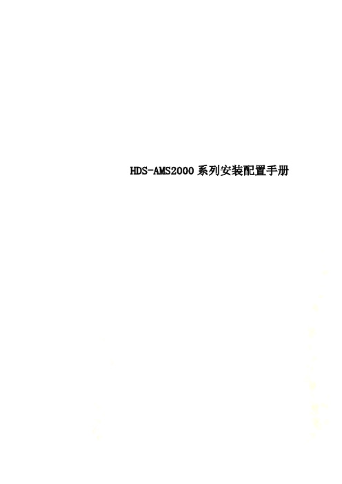
HDS-AMS2000系列安装配置手册AMS2000安装配置手册目录第1章AMS2000概述 ________________________________________________________ 51.1硬件概述______________________________________________________________________ 5 1.2技术亮点_____________________________________________________________________ 14第2章存储硬件安装________________________________________________________ 152.1磁盘阵列硬件安装配置_________________________________________________________ 15第3章存储软件安装配置____________________________________________________ 193.1整体说明_____________________________________________________________________ 193.2存储配置安装_________________________________________________________________ 193.2.1SNM2安装 ______________________________________________________________________ 193.2.2初始化安装 ______________________________________________________________________ 213.2.3收集Trace信息__________________________________________________________________ 343.2.3.1WEB方式收集Trace ___________________________________________________________ 353.2.3.2SNM2收集Trace ______________________________________________________________ 353.2.4安装License ____________________________________________________________________ 36 3.3系统微码升级_________________________________________________________________ 38第4章HDLM软件安装配置 __________________________________________________ 444.1整体说明_____________________________________________________________________ 44 4.2IBM AIX平台软件安装_________________________________________________________ 44 4.3Solaris主机认盘及多路径配置实例_____________________________________________ 44第5章阵列常用软件配置____________________________________________________ 475.1Volume Migration ____________________________________________________________ 475.1.1功能介绍 ________________________________________________________________________ 475.1.2组成部分 ________________________________________________________________________ 485.1.3操作步骤 ________________________________________________________________________ 49第1章 AMS2000概述1.1 硬件概述AMS2000系列有2100、2300、2500三种型号,其中2500包括直流和交流2种AMS2100:AMS2300:Control Disk Powe Cache BackupPower/Read Panel Front view Rear viewControl Disk Powe Cache BackupPower/Rea Panel Front view Rear viewAMS2500:AMS2500-DC Cache Backup Battery UnitsPower/Ready/ Warning/ Alarm LEDsPanel Assembly Power ON/OFFMAIN SWPowerUnit(RKH)Fan Unit Control UnitCache Backup Battery (Option ) Front view Rear view扩展柜:高密扩展柜:AMS2000系列多了一种高密扩展柜,容量为48块盘,实际上是从中间分开的两个柜子,左右两边的每个柜子各24块盘。
A-TControls 3R2500和3R3500双工阀门控制器安装与维护手册说明书

1 Contents1 Contents (1)2 Introduction (2)3 Design (2)4 Operation (2)4.1 Double Acting (DA) (2)4.1.1 CCW Movement (2)4.1.2 CW Movement (2)4.2 Spring Return (SR) (3)4.2.1 CCW Movement (3)4.2.2 CW Movement (3)4.3 Spring Return (SO) (3)4.3.1 CW Movement (3)4.3.2 CCW Movement (3)5 Installation (4)5.1 Installation on Valves (4)5.2 Air Supply (4)5.3 Lubrication (4)5.4 Travel Adjustment (4)6 Disassembly Procedures (5)6.1 Removing End Caps (5)6.1.1 DA & DR Models (5)6.1.2 SR & SO Models (5)6.2 Removing Piston(s) (5)6.3 Removing the Pinion (6)7 Changing Configurations (6)7.1 3R2500 Fail CW to Fail CCW (DA to DR, SR to SO) (6)7.2 3R3500 Fail CW to Fail CCW (DA to DR, SR to SO) (7)8 Assembly Procedure (7)8.1 Assembling Pinion (7)8.2 Assembling Piston(s) (7)8.3 Assembling End Caps (7)8.4 Setting Stop Bolts (8)9 Spare Parts (9)10 Bill of Materials (9)2 IntroductionThe following Installation and Operation Manual is a living document and will continuously be updated as the implementation of the 3R Scotch Yoke Actuators occurs. If you have any questions on the 3R Scotch Yoke Actuators, please contact A‐T Controls.NOTES:∙This manual is also applicable to the Series 2R 2500 and 3500 Scotch Yoke Actuators.∙For the sake of this document, the Drive Shaft may be referred to as the Pinion. Any instances of these two terms are referring to the Drive Shaft (3) in Bill of Materials.∙Throughout this document numbers may be seen in parentheses after a component. These numbers correspond to the numbers in the Bill of Materials that can be found toward the end of the document.3 DesignTriac 3R2500 & 3R3500 Scotch Yoke Actuators are designed and engineered to provide high cycle-life to meet the demands needed. They are offered in both double acting and spring return configurations that feature:∙Dual Travel Stops for open and close adjustment of 0±5° to 90±5°∙Multiple Temperature optionso Standard working temperature (‐5°F to 175°F)o Low temperature ( ‐45°F to 175°F)o High temperature (0°F to 300°F)∙Maximum working pressure 150 psi∙Air Supply Pressure of 40 ‐ 150 psi∙Operating media ‐ clean dry air, nitrogen, non‐corrosive gas or light hydraulic oil.∙NAMUR ‐ VDI/VDE 3845 accessory mounting∙ISO 5211 Valve mounting 4 Operation4.1Double Acting (DA)4.1.1CCW MovementApplying air pressure to Port 1 pressurizes the inside chamber and drives the piston(s) of the actuator outward. This action results in the counterclockwise rotation of the drive shaft. As the piston(s) are driven outward, air is exhausted from the outside chamber(s) through Port 2.4.1.2CW MovementApplyingairpressure to Port 2 pressurizes the outside chamber(s) and drives the piston(s) of the actuator inward. This action results in the clockwise rotation of the drive shaft. As the piston(s) are driven inward, air is exhausted from the inside chamber through Port 1.4.2 Spring Return (SR)4.2.1 CCW MovementApplying air pressure to Port 1 pressurizes the inside chamber and drives the piston(s) of the actuator outward. This action results in the counterclockwise rotation of the drive shaft. As the piston(s) are driven outward, the spring(s) are compressed, storing energy, and air is exhausted from the outside chamber(s) through Port 2. 4.2.2 CW Movement∙ With no air assist : Exhausting air from the inside chamber through Port 1 allows the stored energy in the compressed spring(s) to force the piston(s)inward. This action results in the clockwise rotation of the drive shaft.∙ With air assist : Applying air pressure to the outside chamber(s) through Port 2 forces the piston(s)inward. This action results in the clockwise rotation of the drive shaft. As the piston(s) are driven inward, from the stored energy in the compressed spring(s) and air pressure, air is exhausted from the inside chamber through Port 1.4.3 Spring Return (SO)4.3.1 CW MovementApplying air pressure to Port 1 drives the piston(s) outward, which compresses the spring(s) and turns the drive shaft clockwise as the air volume on the outside of the piston(s) exhausts through Port 2. 4.3.2 CCW Movement∙ With no air assist: Exhausting air from the inside chamber through Port 1 allows the stored energy in the compressed spring(s) to force the piston(s) inward. This action results in the counterclockwise rotation of thedriveshaft.∙ With air assist: Applying air pressure to the outside chamber(s) through Port 2 forces the piston(s) inward. This action results in the counterclockwise rotation of the drive shaft. As the piston(s) are driven inward, from the stored energy in the compressedspring(s) and air pressure, air is exhausted from the inside chamber through Port 1.5 Installation 5.1 Installation on ValvesWARNING : FOR YOUR SAFETY, IT IS IMPORTANT THAT THE FOLLOWING PRECAUTIONS BE TAKEN BEFORE ANYDISASSEMBLY OF THE ACTUATOR OCCURS.▪ Depressurize the lines and cylinder of the actuatorbefore removing any components.▪ On spring return actuators, be careful to loosen theend cap bolts evenly due to the preload on the springs.Triac actuators are mounted directly to valves or adapted to the valve by means of an intermediate bracket and coupler. The coupler adapts the output of the actuator to the valve shaft. Pipelines can behorizontal, vertical, or other positions. When mounting the actuator to a valve using a mounting kit; the drive shaft, coupling device and valve stem should becentered and concentric to prevent any side loading to the bottom pinion radial bearing and valve stem seal area. After mounting, it may be necessary to adjust the end of travel stop for proper open or closed valve position. Pneumatically stroke the actuator several times to assure proper operation with no binding of the coupler.5.2 Air SupplyPneumatic piping to the actuator and associated accessories should follow the best practices for instrument pneumatic piping systems:∙ Line shall be free of water, oil, pipe sealant or other contaminants.∙ Operating medium is to be filtered dry air or inert gaswhich is filtered to 50‐micron particles size or less.∙ Actuator shall be supplied with proper air pressure and air volume. ∙ Triac 3R Scotch Yoke Actuators shall not exceed a maximum working pressure of 150 psi. ∙ Spring Return Models:Note: If exhaust port is not piped, it is important that the exhaust port is not exposed to a corrosive atmosphere.Please contact A ‐T Controls for possible solutions if non ‐typical conditions exist.5.3 LubricationTriac 3R Scotch Yoke Actuators are lubricated from the factory and no additional lubrication is required unless the actuator will be performing more than 100,000 cycles.∙ If more than 100,000 cycles will be performed, an oil mist lubricator is recommended.[1] [2]o Use oil type VG32 Class in temperature range from 15 to 158°Fo Set oil mist lubricator to lowest setting. [1]: If a Triac Scotch Yoke Actuator has been in operation with oil mist lubrication, it cannot be discontinued. [2]: If the actuator is equipped with a pneumatic positioner or controller, oil mist lubricated air shall not be used unless the instrument manufacturer indicates that used instrument is compatible with lubricated air.5.4 Travel AdjustmentWARNING : TO AVOID CATASTROPHIC FAILURE TO ACTUATOR,AIR MUST BE REMOVED FROM ACTUATOR BEFORE ANY TRAVEL ADJUSTMENTS ARE MADE.The Triac 3R Scotch Yoke Actuators have travel stopadjustments in both the clockwise andcounterclockwise directions. A 5° overtravel featureprovides adjustments from ‐5° to +5° at the 0° clockwiseposition, and from 85° to 95° at the 90° counterclockwise position.All actuated valves require accurate travel stop adjustments at both ends of the stroke to obtain optimum performance and valve seat life. Theaccumulation of tolerances in the adaption of actuators to valves is such that there must be a range ofadjustment for both ends of the stroke to achieve the expected performance. See the valve manufacturer’s IOM on how the travel should be adjusted. The following are typical features seen:∙ Ball & Plug Valves: require precise adjustment at the open and closed position. This is to protect the seat from the flow media and to assure absolute shut ‐off in the closed position.∙ Butterfly Valves: require precise adjustment at the open and closed position. This is to assure full shut ‐off, to prevent disc overtravel which can damage the seat in the closed position, and to assure maximum flow in the open position.∙ Tee Assemblies: where two valves are operated in tandem through a single operator, (3‐wayconfiguration) require precise adjustment at both ends of the stroke. This is to assure the seating of both valves.6 Disassembly ProceduresWARNING : FOR YOUR SAFETY, IT ISIMPORTANT THAT THE FOLLOWING PRECAUTIONS BE TAKEN BEFORE ANY DISASSEMBLY OF THE ACTUATOR OCCURS.▪ Depressurize the lines and cylinder of the actuatorbefore removing any components.▪ On spring return actuators, be careful to loosen the endcap bolts evenly due to the preload on the springs. ▪ Disconnect electrical supplies6.1 Removing End Caps6.1.1 DA & DR Models1. Loosen both the Clockwise (Right) andCounterclockwise (Left) Travel Stop Bolt Nuts (12). 2. Back out Travel Stops Bolts (11) about six turns sothe Travel Stop Cam (7) does not interfere with the Travel Stop Bolts.3. Using a 14mm hex key wrench remove the 4 End CapBolts (23) from each side.4. Remove End Caps (22) away from the Actuator Body(33). 6.1.2 SR & SO Models1. Loosen both the Clockwise (Right) andCounterclockwise (Left) Travel Stop Bolt Nuts (12). 2. Back out Travel Stop Bolts (11) about six turns so theTravel Stop Cam (7) does not interfere with the Travel Stop Bolts.3. Using a 14mm hex key wrench remove the 4 End CapBolts (23) from each side.4. Remove End Caps (22) away from the Actuator Body(33).CAUTION! Make sure to remove end cap bolts evenly as there is preload from the spring.WARNING! Do NOT touch the Pre ‐Tensioning Bolt (29) or the Pre ‐Tensioning Nut (25). The SpringAssemblyis preset from the factory. Any adjustments could result in injury or death.6.2 Removing Piston(s)NOTE : Make sure to designate or mark the positions of the piston(s) and pinion during disassembly. The piston and yoke positions will change relative to their original positions.1.If End Caps (22) are not removed, see Removing EndCaps Section for procedure to remove the End Caps before continuing.2.Rotate the Pinion (3) until the Piston(s) (16) are atthe end of the Actuator Body (33). This can be done by turning the Pinion (3) with a wrench on the flats located at the top of the pinion.3.Remove the Piston(s) (16) from the cylinder.6.3Removing the Pinion1.If End Caps (22) and Piston(s) (16) are not removed,see Removing End Caps Section and RemovingPiston(s) for procedures to remove the End Capsand Piston(s) before continuing.2.Set the Actuator Body on an end.3.Rotate the Pinion (3) until the flat side of the YokePin (6) is facing upward.NOTE: There are two different sides to the Yoke Pin (6). A flat smother side and a side that is peened.ing a punch rod on the flat side of the Yoke Pin (6),knock out the Yoke Pin.CAUTION: Do not damage the Yoke (5).5.Remove Drive Shaft Snap Ring (35), Support Washer(36) and Support Bushing (37) located at top of thePinion (3).6.Tap the top of the Pinion (3) lightly with a plasticmallet to remove the Pinion from the upper andlower drive shaft bushings (2, 9).WARNING: When removing the Pinion (3),the Travel Stop Cam (7) and Yoke (5) must beguided off the Pinion and removed from theActuator Body (33) cylinder while removingthe Pinion.7 Changing Configurations7.13R2500 Fail CW to Fail CCW (DA to DR,SR to SO)NOTE: Make sure to designate or mark thepositions of the piston(s) and pinion duringdisassembly. The piston and yoke positionswill change relative to their originalpositions.1.If End Caps (22) and Piston(s) (16) are not removed,see Removing End Caps Section and RemovingPiston(s) for procedures to remove the End Capsand Piston(s) before continuing.2.Set Actuator Body (33) on its end so the short side ofthe body is facing upward.3.Rotate the Pinion (3) until the flat side of the YokePin (6) is facing upward.NOTE: There are two different sides to theYoke Pin (6). A flat smother side and a sidethat is peened.ing a punch rod on the flat side of the Yoke Pin (6),knock out the Yoke Pin and remove from ActuatorBody (33) cylinder.CAUTION: Do not damage the Yoke (5).5.Without rotating the Pinion (3), rotate the Yoke (5)180°.6.Replace the Yoke Pin (6) by putting the flat side infirst and hitting the pin onthepeenedside.7.Grease cylinder surface with multi‐purpose grease.8.Rotate the Piston (16) 180° from original position sothat the Piston Roller (32) is properly seated in the Yoke (5).9.Rotate the Pinion (3) 90° counterclockwise toconfirm proper alignment.10. See Assembling End Cap Section and Setting StopBolts Section to complete configuration change.7.23R3500 Fail CW to Fail CCW (DA to DR,SR to SO)NOTE: Make sure to designate or mark the positions of the piston(s) and pinion during disassembly. The piston and yoke positions will change relative to their original positions.1.If End Caps (22) and Piston(s) (16) are not removed,see Removing End Caps Section and RemovingPiston(s) for procedures to remove the End Capsand Piston(s) before continuing.2.Grease Actuator Body (33) cylinder surface withmulti‐purpose grease.3.With the Pinion (3) in the counterclockwise positionwhen the Piston(s) (16) were removed, rotate thePiston(s) 180° from original position.4.Push the Piston(s) (16) into the Actuator Body (33)making sure the Piston(s) Roller Bearings (32) areproperly seated in the Yoke (5).5.Rotate the Pinion (3) 90° counterclockwise toconfirm proper alignment.6.See Assembling End Cap Section and Setting StopBolt Section to complete configuration change.8 Assembly Procedure8.1Assembling Pinion1.Inspect all parts for wear and replace any worn partsas needed. Make sure all parts are greased withmulti‐purpose grease.2.If rebuilding, on the Pinion (3) replace:a.Drive Shaft Lower O‐ring (1)b.Drive Shaft Lower Bushing (2)c.Drive Shaft Upper Bushing (9)d.Drive Shaft Upper O‐ring (10)3.Install the Drive Shaft Middle Bushing (4) that goesbelow the Yoke (5) onto the Pinion (3).4.With the Yoke (5) being supported in the ActuatorBody (33) cylinder, insert the Pinion (3) through thebottom Actuator Body cylinder opening, Yoke (5),Drive Shaft Middle Bushing (4) that goes above the Yoke, Travel Stop Cam (7) and then throughActuator Body (33) cylinder top opening.NOTE: Make sure that the Travel Stop Cam(7) is oriented for correct configuration.5.Install the existing, or if rebuilding new, SupportBushing (37), Support Washer (36) and Drive ShaftSnap Ring (35).6.Verify the orientation of the Yoke (5) and align theYoke Pin (6) hole on the Yoke with correspondinghole on the Pinion (3).7.Relace the Yoke Pin (6) by putting the flat side in firstand hitting the Yoke Pin on the peened side.8.2Assembling Piston(s)1.Inspect all parts for wear and replace any worn partsas needed. Make sure all parts are greased withmulti‐purpose grease.2.If rebuilding, on the Piston(s) (16) replace:a.Piston O‐Ring (17)b.Piston Guide Ring (18)3.Verify the orientation of the Piston(s) (16) as neededfor designed operation.4.Push the Piston(s) (16) into the Actuator Body (33)cylinder making sure the Piston(s) Roller Bearing(s)(32) are properly seated in the Yoke (5).5.Rotate the Pinion (3) 90° counterclockwise toconfirm proper alignment.8.3Assembling End Caps1.Inspect all parts for wear and replace any worn partsas needed.2.Install the existing End Cap O‐ring (27) or replace theEnd Cap O‐ring if rebuilding.3.Verify the Pinion (3) is rotated so that Piston(s) areas far into the Actuator Body (33) cylinder aspossible.4.Install the Spring Assembly End Cap (22) or End Caponto the cylinder body.∙Spring Return: Thread the 4 End Cap Bolts (23)down evenly, moving between the bolts, until the End Cap (22) and Actuator Body (33) contact.Repeat for opposite End Cap.∙Double Acting: Thread the 4 End Cap Bolts (23)until the End Cap (22) and Actuator Body (33)contact. Repeat for opposite End Cap.5. Tighten End Cap Bolts (23) to 1,440 in‐lbs using a14mm hex key wrench.8.4Setting Stop Bolts1.If rebuilding, replace the Travel Stop O‐Ring (14) onthe Travel Stop Bolt (11).2.Rotate the actuator to the desired clockwiseposition. 3.Tighten the Clockwise (Right) Travel Stop Bolt (11)until contact with the Travel Stop Cam (7).4.While holding the Clockwise (Right) Travel Stop Bolt(11), tighten the Travel Stop Nut (12) until theTravel Stop Washer (13) contacts the Actuator Body(33); compressing the Travel Stop O‐ring (14).5.Rotate the Actuator to the desired counterclockwiseposition.6.Tighten the Counterclockwise (Left) Travel Stop Bolt(11) until contact with the Travel Stop Cam (7). 7.While holding the Counterclockwise (Left) TravelStop Bolt (11), tighten the Travel Stop Nut (12) until the Travel Stop Washer (13) contacts the ActuatorBody; compressing the Travel Stop O‐ring (14).9 Spare Parts10 Bill of MaterialsA‐T Controls product, when properly selected, is designed to perform its intended function safely during its useful life. However, the purchaser or user of A‐T Controls products should be aware that A‐T Controls products might be used in numerous applications under a wide variety of industrial service conditions. Although A‐T Controls can provide general guidelines, it cannot provide specific data and warnings for all possible applications. The purchaser / user must therefore assume the ultimate responsibility for the proper sizing and selection, installation, operation, and maintenance of A‐T Controls products. The user should read and understand the installation operation maintenance (IOM) instructions included with the product and train its employees and contractors in the safe use of A‐T Controls products in connection with the specific application.While the information and specifications contained in this literature are believed to be accurate, they are supplied for informative purposes only. Because A‐T Controls is continually improving and upgrading its product design, the specifications, dimensions and information contained in this literature are subject to change without notice. Should any question arise concerning these specifications, the purchaser/user should contact A‐T Controls.For product specifications go to http://a‐/Downloads/A‐T Controls, Inc. • 9955 International Boulevard, Cincinnati, OH 45246 • Phone: (513) 530‐5175 • Fax: (513) 247‐5462 • www.a‐。
HDS AMS2500

前端模組設備有配有指示燈號 正常狀況顯示綠燈,故障顯示紅燈 更換可由前端拉桿拉出後做更換
AMS2000系列產品概述
1. 2. 3. 4.
Host Connector (FC port or iSCSI) Controller 0 Controller 1 And 5 .Power Supply
AMS2000系列產品概述
AMS2000系列產品概述
6. RST :Reset Button 7. Reset LED (橘燈) 8. C-Power LED (綠燈):亮時表示暫存記憶體在做備份 9. Maintenance Port(LAN) 10.Management Port(LAN) 11~14.ENC Connector Path 15.UPS連接孔 16.電池擴充連接器 17.Remote Adapter connector
AMS2500: Components
AMS 2500: Groups
AMS 2500:Settings
AMS 2500: Performance
AMS 2500: Alerts & Events
AMS 2500 :Create Raid Group
AMS 2500 -> Groups -> Logical Units -> RAID Groups Click “Create RG” to create a new raid group.
– Adaptable Modular Storage 2300
240 hard disk drives – base unit plus 15 expansion units Front-end ports: 8 Fibre Channel or 4 iSCSI Back-end: 16 - 4x4 SAS Wide link Maximum 75 RAID Groups with 4096 Logical Units
S使用说明-DSAM2500(中文)
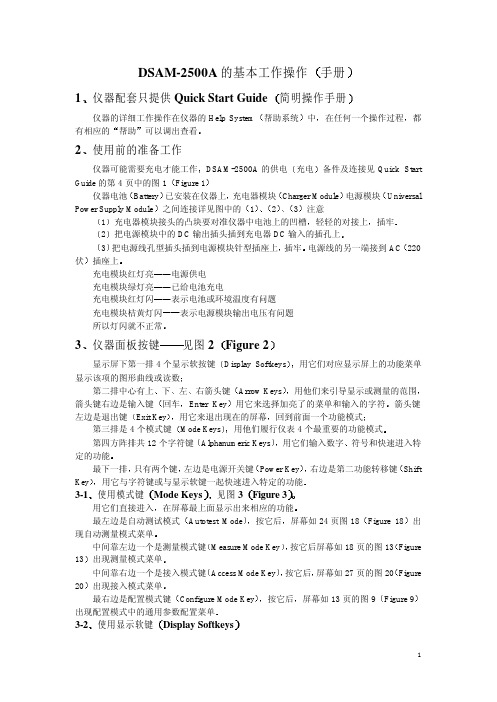
DSAM-2500A的基本工作操作1简明操作手册帮助系统在任何一个操作过程帮助2DSAM-2500A的供电备件及连接见Quick Start Guide的第4页中的图1仪器电池已安装在仪器上Charger Module UniversalPower Supply Module131ÇáÇáµÄ¶Ô½ÓÉÏ把电源模块中的DC输出插头插到充电器DC输入的插孔上3插牢220伏充电模块红灯亮电源供电充电模块绿灯亮已给电池充电充电模块红灯闪表示电池或环境温度有问题充电模块桔黄灯闪表示电源模块输出电压有问题所以灯闪就不正常仪器面板按键见图2显示屏下第一排4个显示软按键第二排中心有上左Arrow Keys用他们来引导显示或测量的范围回车用它来选择加亮了的菜单和输入的字符Exit Key用它来退出现在的屏幕第三排是4个模式键第四方阵排共12个字符键符号和快速进入特定的功能只有两个键Power Key右边是第二功能转移键3-1Mode Keys见图3ÔÚÆÁÄ»×îÉÏÃæÏÔʾ³öÀ´ÏàÓ¦µÄ¹¦ÄÜAutotest Mode按它后Figure 18中间靠左边一个是测量模式键Figure 13中间靠右边一个是接入模式键屏幕如27页的图20出现接入模式菜单Configure Mode Key按它后Figure 93-2Display Softkeys显示屏下的4个软键如图4Limits Level ModeÓÖÈçͼ5Select¶ø°´Í˳ö下面的软键就退出到前面显示的屏幕使用转移捷径键 先按转移键后按字符键或显示软件也称为第二功能的图形标志在相应的字符右下角Shift5ϵͳ°ïÖú¼´ÒâÕâ¸öģʽÔÚ²Ù×÷¹ý³ÌÖÐÒª¾-³£Ê¹ÓÃ4Help System¹¤×÷ÊÖ²áon-band²Ù×÷¹ý³ÌÖÐShift5ÒÔ±ã»ñµÃÆä¸üÏêϸµÄ°ïÖúÐÅÏ¢A从模式菜单进入如图6在自动测试模式下按Shift和5健后出现有的屏幕下箭头键来选择自动测试下的项目Combo Auto Test EnterÔÙÓÃÉϼÓÁÁ×éºÏ×Ô¶¯²âÊÔ¸ÉʲôWhat Combo Auto Test Does回车就逐步进入你要了解的详细内容想进入其它帮助内容要用帮助屏下的软键Menu³öÏÖ°ïÖúÖ÷²Ëµ¥Ï¼ýÍ·¼üÑ¡ÔñÐè°ïÖúµÄÏîÄ¿Forward½øÈë¼ÓÁÁµÄÏîÄ¿按向后对应的软键ExitÍ˳ö°ïÖúϵͳ5ÏÈÒª¶ÔÒDZí½øÐбØÐèµÄ²ÎÊýÅäÖÿÉÒÔ¸ù¾ÝÄãµÄÒªÇóºÍÐËȤ²»¶ÏÉîÈëÁ˽âÈ¥ÏêϸµÃµ½ÅäÖõÄÒªÇóºÍ½ø³Ì°´ConfigureÈçͼ9屏幕有4个配置模式菜单GeneralMeasureChannel PlanAccessÆÁĻϵÚÒ»ÅŵÄ4个键最重要的依次是Channel Plan, Measure和GeneralChannel PlanʹÓÃÕ߱ش¦ÓÚʵ¼ÊµÄÍøÂçƵµÀ¹æ»®Öе«Èç¹ûÒÇÆ÷´æÓÐChannel Plan没有这个频道所以DSAM必需先配置好频道表 在配置屏幕下按Channel Plan对应的软键如图11ÏÂÐÐƵµÀ¹æ»®downstream plans³öÏÖÒÇÆ÷ÏÖ´æµÄƵµÀ±í有NCTAµÄƵµÀ±í²»ÄÜÓÃ按规划对应软键下箭头键选择编辑回车就出现NCTA 的频道列表从低端向高端进行编辑NCTA的002ÁбíÖÐËùÓвÎÊý¶¼ÎªÔ-NCTA的Enabled: 加亮yes OKType:FM或数据频道DUAL双伴音电视频道DIG QAM电视频道DOCSIS DOCSIS数据频道Ä¿Ç°¾ø´ó¶àÊýÊÇÈ»ºó±à下的各项参数按Clear清除原频道号最后OK确认名称一般可以不加用字符键入Frequency: 按ClearÔÙÓÃÊý×Ö¼üÈë¸ÃƵµÀƵÂÊVideo Signal: 加亮D/PAL或K/PAL回车Scrambled: 如加密加亮yes回车Audio Offset:如果是SINGLE只有Channel NumberDUAL目前没有ÔòҪѡDIGÒª±à¼-µÄÒ²ÓÐChannel Number,Label但其中Frequency: 回车用数字键入电视QAM频道的中心频率OK确认调制缺省是64QAM¼ÓÁÁ256QAM再回车QAM StandardÈç¹ûÊÇÃÀÖÆ6MHz要改为Annex BSymbol Rate: clear后用数字键入该电视QAM频道的符号率回车或OK即可反转频谱是Annex B为noOK确认DOCSIS是CM与CMTS之间传输数据的频道DOCSIS频道参数只有一项与电视QAM频道不一样改为EuroDOCSIS×¢Òâ其它DOCSIS频道参数编辑与电视QAM频道相同按Next对应的软件进入第二频道的编辑一步一步把你的工作频道或国家的1Z42增补频道都可以编进去避免与标准频道数矛盾Measure³ýƵµÀ¹æ»®Íâ设限设置其它设置其中设限设置是Auto test中一般都有的超出这个范围就不合格在加亮Limit sets回车后有列表即选择要设限测量的项目然后回车Edit Cable Modem可把缺省数值改编为你需要的数值在Other Settings项中最佳设置让你选择调谐增量调谐顺序等通用参数设置比较重要的有对比度Battery Conservation地区性选择 视使用环境和使用人员而定General调到你应要的位置后回车即可电池维持是为了延长电池的使用时间进入Configure加亮Battery conservation回车后有oplimize Battery LifeÁ½Ïî仪器关断10加亮选定回车即可背景光关断可选开机后515秒钟关掉或常开加亮选定回车即可地区性选择国家信号电平单位调制误码率单位VGeneral回车后再加亮Signal Level UnitsϼýÍ·Ñ¡ÔñdB通用参数很多根据需要可逐项选择设置至此重要设置完毕可以进入测量模式了测量模式是仪表使用最频繁的功能模式有LevelminiscanUpstream Spectrumdocsis四种测量Measureºó6.1电平测量数字信号平均功率加亮Level回车如图14所示在显示中有频道号标识频率伴音载波电平V比底部有4个软键对应的工具栏设置按对应的软键后有频道调谐加亮它是缺省的位置频道号频率调谐是不知道频道号却知道频率时FM测量就可以用这个设置回车频率再回车就进入这个的电平测量Channel Plans回车用来查看规划中有没有你要测量的频道用频道调谐测量是不行的所以在编辑频道规划时如我国标准1增补Z1¾Í²»»á³öÏÖÕâÖÖÇé¿ö设限按对应的软键进入电平测量下各种项目设限装态下的结果回车左上角显示合格与否Fail各个项目的缺省limits值可以重新编辑回车出现Select a limits set to edit回车DefaultÔÙ¼ÓÁÁÏàÓ¦Ïî½øÐбà¼-数字键入新值这个过程实际又回到测量配置的左边靠中是V iew自动参考自动调整显示屏幕的标尺缺省状态格格也可加亮回车选择Mini Scan加亮回车显示12个频道扫描结果加亮tableÔÙ°´GraphÈí¼üÓֻص½Í¼ÐÎÏÔʾ单个频道左边是File储存打开打印请按各项子菜单各项提示和操作这一部分此功能可同时显示12个频道扫描结果程序是Downstream PlanMiniscan Channel然后在实际channel plan中进行选择EnterÖдò¹´¼´¿ÉÏêϸÏÔʾ²Ù×÷Çë²Î¿¼6.3上行频谱测量分析上行5与和不同的显示主要在view上缩放而Peak HoldÓÃÀ´Ë²¼ä²¶×½ÉÏÐÐ×î´ó¸ÉÈÅÂö³å重置再去其它显示操作都与类似这个模式的测量是DSAM-2500A独有的仪器代替CM在用户端接入进入也很简单DOCSIS如果你的系统有多个DOCSIS QAM 频道则要选定要测的那个频道整个测量过程最长需几分钟下行通道确认上行通道电平调整仪表利用与CMTS连接的DHCP进行初始化测试子网掩码仪表利用与CMTS连接的TFTP进行连通测试确认网络的连通性仪表利用获得的配置参数向CMTS进行登记TFTP和TOP服务器的IP地址测试显示lest in progress分13ÉÁ˸×ÅÕý½øÐÐÖоß˵Ã÷锁定下行频道出现downstream signal error没有QAM锁定存在的问题可能有被测频道是电视QAM相关设置数据不对低于65dB或调制误码过大MER<21dB MER<26dB或下行通道质量不稳定没有收到UCDÏÔʾ»á³öÏÖerror信息CMTS没有响应CMTS在电平调整完成前停止响应原因可能是CMTS工作不正常CMTS中止电平调整如果error是DHCP server provided missing or invalid IP parametersÔ-ÒòÊÇDHCP服务器没有提供测试需要的足够的参数如果error是The DHCP Server is not responding·þÎñÆ÷¹Ø±Õ»ò²»¿É´ï服务器上没有配置文件原因是TFTP服务器没有找到指定的配置文件如果error是The TFTP sever is not responding如果error是There is a TFTP Protocol failureÉÏ如果error是There is an error retrieving configuration file from server如果error是There is an error parsing the configuration file如果error是The CMTS did not re spond to the registrations request如果error是Received an authentication failure from CMTS如果error是Received a class of service failure from CMTS最后登记失败原因很复杂如果整个过程没有问题DOCSIS频道的频率MER MER冗余FEC前后的BERDOCSIS频道的频率MER和level的冗余都与limits有关 Measureshift+5EnterEnter用上下箭头翻出相应部分的详细叙述7Auto Test Mode组合自动测试是用户设置的视频频道与电缆调制解调器组合的自动测试程序视频频道自动测试是用户设置的数字/模拟电视频道电平测试的程序电缆调制解调器是用户设置的对一个或多个DOCSIS频道上/下行连接性验证按下Autotest功能模式键就直接进入自动测试模式菜单下箭头键加亮你要履行的测量方式注意仪表的配置已经完成才能执行自动测试还必须做测量配置中的设限设置Measure 图19是组合自动测试显示屏下面有Select a limit setÀ¸Ï¼ýÍ·Ñ¡Ôñ¼ÓÁÁÏîÔÙ°´¿ªÊ¼软键仪表扫描自动测试结果概要视频Cable modemÏȼÓÁÁËü»Ø³µºó¾ÍÓÐautotest detailsƵµÀƵµÀ±ê¼ÇV再按Summary软键又回到可转换到其它项目Video Channels也和Combo一样的被测系统必须有DOCSIS频道否则不能执行8Access ModeͬʱҲ¿ÉÓÃDSAM PC软件去同步你的数据图20Synchronizing仪器必须先安装选件DSAM PC软件才能进行同步工作传输接口有仪器顶部的以太网接口和电池充电器上的R232串口用工作文件夹去建立一个新的测量文件文件夹删除你长时间不需要的文件夹或清除已通过DSAM PC同步的所有文件夹其它表与表之间复制配置ConfigureÈç¹ûÄãÓÐÁíÍâµÄDSAM-2500A°ÑÒ»¸ö±íµÄÅäÖô«µ½ÁíÒ»¿é±íÖÐ更换保护片当仪表长期使用或不慎划伤更换时不要用锋利工具104Cµ÷г·Ö±æÂÊÊý×Ö50KH zƵµÀ´ø¿í8KH zDSAM-2500BCW NTSC范围120 dB0.1 dB分辨率带宽2C数字电平测量调制方式QPSKDVB 范围120 dB0.1 dB分辨率带宽2C上行频谱扫宽65MHz DSAM-2500B 4小于1.8秒扫描显示与范围10dB6个垂直分度分辨率带宽125VDOCSISDOCSIS1.0和1.1上行发射范围双工滤波过渡带565最小下行DOCSIS中心频率100MHz542最小下行DOCSIS中心频率91MHz QPSK和16QAM由CMTS分配发射输出C时典型值16QAM 115dBV下行QAM解调调制方式ITU-T J.83B可选锁定范围3-1555总功率BERºó10-9MER21典型28精度2dBEVM64QAM范围5.8% 精度0.5% 2.0%1.0% 4.0%1.4% 5.0%1.1%Annex A 6.952Msps对64和256QAM5.057Msps对64QAMAnnex C 5.361Msps对256QAM75欧姆100伏交流在充电器模块DB9标准或选配直连电缆打印机兼容性RJ45TCPV1.1主模今后软件发布英语第二语言为选购西班牙德语演示240点阵12cm25cm7cm重量-20 C注1¿É¼ì²â·¶Î§2120dBµäÐÍ在4MHz 1.0dBCC有附加不可预测 在64QAM4+50dBmV电平100µäÐÍ电源充电器模块输入工作电压范围14伏直流反向极性 接头-20+50-20+8060C0C输出3小时快速充电率10% @ 7.2V 最大充电时间Li-Lon电池 电池工作时间典型1000mA6.5СʱµçÔ´¹©µçÄ£¿é9047+12VDC×î´ó¸ºÔصçÁ÷。
2500说明书内容
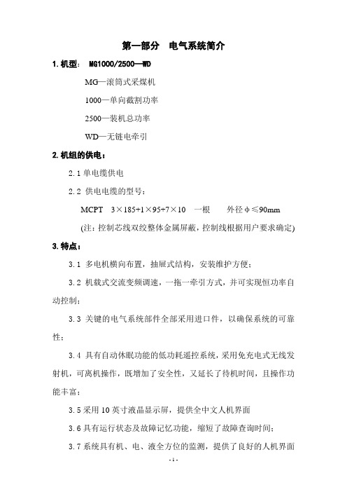
第一部分电气系统简介1.机型:MG1000/2500—WDMG—滚筒式采煤机1000—单向截割功率2500—装机总功率WD—无链电牵引2.机组的供电:2.1单电缆供电2.2 供电电缆的型号:MCPT 3×185+1×95+7×10 一根外径φ≤90mm(注:控制芯线双绞整体金属屏蔽,控制线根据用户要求确定) 3.特点:3.1多电机横向布置,抽屉式结构,安装维护方便;3.2 机载式交流变频调速,一拖一牵引方式,并可实现恒功率自动控制;3.3关键的电气系统部件全部采用进口件,以确保系统的可靠性;3.4具有自动休眠功能的低功耗遥控系统,采用免充电式无线发射机,可离机操作,既增加了安全性,又延长了待机时间,且操作功能丰富;3.5采用10英寸液晶显示屏,提供全中文人机界面3.6具有运行状态及故障记忆功能,缩短了故障查询时间;3.7系统具有机、电、液全方位的监测,提供了良好的人机界面显示;3.8各电机采用分步启/停控制,既降低了起动电流对供电网络的冲击,又方便了对采煤机操作、检修和维护;3.9 具有开机预警、瓦斯监测、超限停机功能;3.10 采煤机能根据刮板运输机的负荷情况自动调速,实现对运输机的保护(配套有集控系统的采煤工作面)。
4.电气系统的基本配置:4.1牵引调速装置(电气控制箱)型号:ZJT-2500/3300C额定电压:3300V额定电流:510A4.2截割电机型号:YBCS-1000(A)额定功率:1000kW额定电压:3300V额定电流:199A额定频率:50Hz额定转速:1485r/min防护等级:IP56绝缘等级:H工作制:SI冷却方式:水套、端盖水冷冷却水压力:≤2Mpa冷却水流量:≥3m3/h4.3牵引电机型号:YBQYS-150额定功率:150kW额定电压:660V额定电流:156A频率:0~50~100Hz额定转速:1483r/min最大转速:3200r/min防护等级:IP54绝缘等级:H工作制:S14.4破碎电机型号:YBC-160额定功率:160kW额定电压:3300V额定电流:33A额定频率:50Hz额定转速:1480r/min绝缘等级:H工作制:S1冷却方式:水套冷却冷却水压力:≤2Mpa冷却水流量:≥1.2m3/h 4.4泵站电机型号:YBRB-45(G)额定功率:45kW额定电压:3300V额定电流:9.9A额定频率:50Hz额定转速:1460r/min绝缘等级:H工作制:S1冷却方式:水套冷却冷却水压力:≤2Mpa冷却水流量:≥1.2m3/h 4.5遥控接收装置遥控接收装置兼作端头操作站实现整机的操作控制,并具有信号的发送、接收及电源的显示功能。
兰сер2500洒水器安装与维护手册说明书
INSTALLATION AND SERVICEMANUAL FORLANCER SERIES 2500DISPENSERSFAX ENGINEERING:•210-310-7096"Lancer" is the registered trademark of Lancer •Copyright — 2004 by Lancer, all rights reserved.Please refer to the Lancer web site ( ) for information relating to Lancer Installation and Service Manuals,Instruction Sheets, Technical Bulletins, Service Bulletins, etc.6655 LANCER BLVD. • SAN ANTONIO, TEXAS 78219 USA • (210) 310-7000FAX SALES• NORTH AMERICA – 210-310-7245 • INTERNATIONAL SALES – 210-310-7242 • CUSTOMER SERVICE – 210-310-7242 •• LATIN AMERICA – 210-310-7245 • EUROPE – 32-2-755-2399 • PACIFIC – 61-8-8268-1978 •iNOTES NOTESiii1.INSTALLATION1.1RECEIVINGEach unit is completely tested under operating conditions and thoroughly inspected before shipment. At time of shipment, the carrier accepts the unit and any claim for damages must be madewith the carrier. Upon receiving units from the delivering carrier, carefully inspect carton for visibleindication of damage. If damage exists, have carrier note same on bill of lading and file a claim withthe carrier.1.2UNPACKINGA.Cut band and remove.B.Remove top portion of carton by lifting up.C.Remove top inner carton pad and corners.D.Lift Unit up by plywood shipping base and remove lower portion of carton.E.Inspect unit for concealed damage and if evident, notify delivering carrier and file a claim againstsame.F.Remove plywood shipping base from unit by moving unit so that one side is off the counter topor table, allowing access to screws on the bottom of the plywood shipping base.G.If Unit is to be installed with optional legs, assemble legs to unit by tilting unit. DO NOT LAYUNIT ON ITS SIDE OR BACK.H.Remove accessory kit of loose parts from drip tray.1.3SELECTING A COUNTER LOCATIONThe dispenser is designed to sit on a flat, supported surface capable of supporting a minimumweight of 400 pounds (182 kg). It may be either counter or leg mounted. A template is furnished tocut and/or drill the necessary holes for mounting. When the dispenser is to be permanently boltedto the counter top, seal dispenser base to counter top with a silicone sealant which provides asmooth and easily cleanable bond to the counter.Locate dispenser to allow approximately 15 inches (380 mm) of unobstructed space above and six (6) inches (160 mm) behind the unit for proper air circulation. Air is drawn in through the backgrill and exhausted out of the top grill.1.4CONNECTING THE DRAINA.Remove cup rest. Lift splash plate up and pull out and down on the bottom to remove.B.Remove the drip tray from the unit and connect the drain tube to the drain fitting located on thebottom. Secure drain tube with clamp provided in accessory kit.C.Route the drain tube to a suitable drain and replace the unit's drip tray.1.5FILLING UNIT WITH WATERA.Remove the bonnet from the unit.B.Remove the yellow plastic plug from the fill hole.ing a funnel or tube, fill the water bath compartment with water until it flows out of theoverflow tube into the drip tray. Use bottled water where a water problem exists.D.Replace the yellow plug.11.6CONNECTING TO ELECTRICAL POWERA.Check the dispenser serial number plate for unit's correct electrical requirements. Do not pluginto electrical outlet unless unit electrical configuration, located on serial plate, agrees with localavailable power supply.B.Route the power supply cord to a grounded electrical outlet of the proper voltage andamperage rating, and plug in the unit. This will turn on the refrigeration system and allow it tostart cooling while completing the rest of the installation. Approximately three (3) hours arerequired to form a full ice bank.1.7CONNECTING TO PLAIN WATER SUPPLYSee Figure 1.If unit has no plain water circuits, proceed to Section 1.8.A.Valves 4, 5, and 6 through 8 (on 8 valve units) and valves 3, 4, and 5 (on 6 valve units) haveoptional plain water or carbonated water capabilities. Using Figure 1, determine which valvesare to be plumbed with plain water.ing proper beverage tubing and fittings, connect to water source [must be 35 PSI (2.4 bar) ormore].C.Flush water supply line thoroughly.D.Route tubing through cutout in counter or through access hole in back of unit.E.Leave 12 inches (300 mm) of extra tubing length below the counter for servicing and movingthe dispenser.F.Connect to desired plain water inlet behind splash plate and secure with Oetiker Clamp.G.Turn on water supply and check for leaks.H.Actuate each valve until all air is expelled.Plumbing Diagram, Carbonated/Plain WaterFigure 1232.SCHEDULED MAINTENANCE2.1DAILYA.Remove the nozzle and diffuser from each valve and rinse well in warm water. Do NOT usesoap or detergent. This will cause foaming and off taste in finished product.B.Remove the cup rest and wash in warm soapy water.C.Pour warm soapy water into the drip tray and wipe with a clean cloth.D.With a clean cloth and warm water, wipe off all of the unit's exterior surfaces. DO NOT USEABRASIVE SOAPS OR STRONG DETERGENTS.E.Replace the cup rest, valve diffusers, and valve nozzles.2.2WEEKLYA.Taste each product for off tastes and/or brix changes.B.Remove the bonnet and check the level of water in the water bath. Replenish as required, andreplace the bonnet.2.3MONTHLYA.Unplug the dispenser from power source.B.Remove the bonnet and clean the dirt from the condenser using a soft brush.C.Replace the bonnet and plug in the unit.2.4EVERY SIX MONTHSA.Clean and sanitize the unit using the appropriate procedures outlined in Section 3 of thismanual.2.5YEARLYA Clean water bath interior, including evaporator coils and refrigeration components.B.Clean the entire exterior of the unit.C.Sanitize syrup lines.3.DISPENSER CLEANING AND SANITIZING3.1AMBIENT PROCESSA.The ambient process is the most common method for cleaning and sanitizing dispenserequipment. The detergent should be caustic-based and the sanitizer should be low pH (7.0)chloride solution.B.Disconnect syrup containers and remove product from tubing by purging with carbon dioxide.C.Rinse the lines and fittings with clean, room temperature water to remove all traces of residualproduct.D.Fill lines with a caustic-based (low-sudsing, non-perfumed, and easily rinsed) detergent solu-tion. The solution should be prepared in accordance with the manufacturer’s recommendations,but should be at least two (2) percent sodium hydroxide. Make sure the lines are completelyfilled and allow to stand for at least ten (10) minutes.E.Flush the detergent solution from the lines with clean water. Continue rinsing until testing withphenolpthalein shows that the rinse water is free of residual detergent.F.Fill the lines with a low pH (7.0) chlorine solution containing at least 50 parts per million (PPM)(50 mg/L) available chlorine. Make sure that lines are completely filled and allow to stand forten (10) minutes.G.Reconnect syrup containers and ready Unit for operation.H.Draw drinks to refill lines and flush the chlorine solution from the dispenser.I.Taste the beverage to verify that there is no off taste.3.2VALVESA.Valves may be cleaned and sanitized in the same manner1.Remove cover and disconnect power so not to activate the valve while cleaning. Removenozzle and diffuser. Wash these parts in cleaning solution, then immerse them in a bath ofsanitizing solution for 15 minutes.42.Visually inspect around nozzle area for syrup residue. This area may be cleaned with warmwater and cloth or with the nozzle brush supplied. Wipe off dispensing lever.3.Wearing sanitary gloves, remove, drain and air dry the nozzle and diffuser.4.Wearing sanitary gloves, replace diffuser and twist nozzle into place.5.Connect power and replace cover. Valve is ready for operation.4.TROUBLESHOOTING575.12500 REFRIGERATION DECK ASSEMBLY, R-134A, LANCER ELECTRONIC ICE BANKCONTROL(EIBC), USA ONLY, PN 82-2669 (CONTINUED)(MANUFACTURED FROM 01/99)910115.22500 REFRIGERATION DECK ASSEMBLY WITH ELECTRONIC ICE BANK CONTROL (EIBC),R-134A; PN 82-2049E, 230V/50Hz; PN 82-2103E, 115V/60Hz; PN 82-2098E, 240V/60Hz (CONTINUED)(INTERNATIONAL ONLY)ITEM PART NO.DESCRIPTION125.32500 CONTROL HOUSING ASSEMBLY, ELECTRONIC ICE BANK CONTROL(EIBC)INTERNATIONAL ONLY(CONTINUED)13145.42500 CABINET ASSEMBLY (CONTINUED)15ITEMPART NO.DESCRIPTION5.52500 WIRING DIAGRAM AND HOUSING CONNECTIONS, LANCER ELECTRONIC ICE BANKCONTROL, USA ONLY5.62500 WIRING DIAGRAM, ELECTRONIC ICE BANK CONTROL(EIBC), INTERNATIONAL ONLY1718Directory of USA - Canada Offices,International Offices, and Authorized Distributors(Continued)Directory of USA - Canada Offices,International Offices, and Authorized DistributorsCorporate Office6655 Lancer Blvd. • San Antonio, Texas 78219 • 210-310-7000 • 1-800-729-1500 • FAX 210-310-7250。
中央线2500低电压电机控制中心和开关电源组装说明书
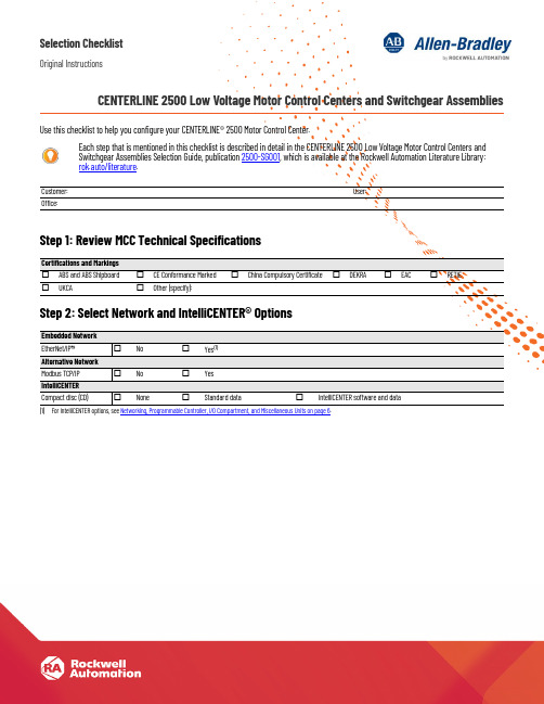
Selection ChecklistOriginal InstructionsCENTERLINE 2500 Low Voltage Motor Control Centers and Switchgear Assemblies Use this checklist to help you configure your CENTERLINE® 2500 Motor Control Center.Step 1: Review MCC Technical SpecificationsStep 2: Select Network and IntelliCENTER® OptionsEach step that is mentioned in this checklist is described in detail in the CENTERLINE 2500 Low Voltage Motor Control Centers andSwitchgear Assemblies Selection Guide, publication 2500-SG001, which is available at the Rockwell Automation Literature Library:rok.auto/literature.Customer:User:Office:Certifications and Markings☐ABS and ABS Shipboard☐CE Conformance Marked☐China Compulsory Certificate☐DEKRA☐EAC☐RETIE☐UKCA☐Other (specify):Embedded NetworkEtherNet/IP™☐No☐Yes(1)(1)For IntelliCENTER options, see Networking, Programmable Controller, I/O Compartment, and Miscellaneous Units on page6.Alternative NetworkModbus TCP/IP☐No☐YesIntelliCENTERCompact disc (CD)☐None☐Standard data☐IntelliCENTER software and data2Rockwell Automation Publication 2500-SR001J-EN-P - September 2022CENTERLINE 2500 Low Voltage Motor Control Centers and Switchgear Assemblies Selection ChecklistStep 3: Select StructureStep 4: Select Power SystemsStructure Enclosure rating ☐IP 42 (standard)☐IP 54☐IP 20ArcShield™ (IEC/TR 61641)☐No (standard)☐Yes Forms of internal separation ☐3b (standard)☐2b ☐4b Type 5☐4b Type 7Mounting configuration ☐Single front (standard)☐Double front (back-to-back)☐Add to existingVertical wireway width ☐200 mm (700 mm total column width)☐300 mm (800 mm total column width)☐400 mm (900 mm total column width)☐500 mm (1000 mm total column width)Depth☐600 mm (single front)☐800 mm (single front)☐1200 mm (double front or back-to-back)☐1600 mm (double front or back-to-back)Ambient temperature, max _________ °CAltitude__________________ metersExternal paint ☐RAL7032 Pebble Gray (standard)☐Other (specify):(1)(1)To provide a more detailed description, use the Notes section that begins on page 8.Internal paint☐Z275 galvanized steel (standard)☐High visibility gloss white☐Other (specify):(1)Master Nameplate☐No☐Yes (up to five lines; 40 characters maximum per line)Line 1:Line 2:Line 3:Line 4:Line 5:Options☐Space heater with thermostat☐Cable supports for vertical wireways ☐Other (specify):(1)Incoming Power Line voltage ☐380V ☐400/415V ☐440/460/480V ☐525/575V☐690V Frequency ☐50 Hz☐60 HzSystem power ☐Delta ☐Grounded Delta☐Grounded wye ☐Grounded wye with impedanceAvailable fault current _________ kABusWithstand/fault ratings ☐50 kA for 1 second ☐50 kA for 3 seconds☐ 65 kA for 1 second ☐ 80 kA for 1 second ☐ 100 kA for 1 secondHorizontal power bus rating☐800 A ☐1250 A ☐1600 A ☐2000 A☐2500 A ☐3200 A ☐4000 A Horizontal power bus material ☐Copper, tin plated (standard)☐Copper, unplated Neutral bus☐None (standard)☐Full rated☐Half ratedVertical distribution bus rating☐300 A (provides 600 A capacity)☐600 A (provides 1200 A capacity)Vertical distribution bus material ☐Copper, tin plated (standard)☐Copper, unplatedStab openingsNOTE: Automatic shutters are included as standard.Protective Earth (PE)Horizontal PE location ☐Bottom (standard)Vertical PE conductor for withdrawable units☐Copper, unplated (standard)☐Copper, tin plated Vertical PE conductor for customer load ☐Copper, unplated (standard)☐Copper, tin platedRockwell Automation Publication 2500-SR001J-EN-P - September 20223CENTERLINE 2500 Low Voltage Motor Control Centers and Switchgear Assemblies Selection ChecklistStep 5: Select Unit DesignsStep 6: Select Unit TypesUnit Configuration–General Outgoing cable access ☐Top☐BottomUnit type☐Standard withdrawable☐Fixed mount☐Withdrawable with SecureConnect™Nameplates (white with black lettering)☐Engraved acrylic (standard)Unit Control Power Voltage☐24V DC☐110/115/120V AC☐220/230/240V AC Source☐Central control power transformer (standard)☐Line to neutral ☐Remote control power sourceIndividual control transformer:☐75VA ☐150VA☐250VA☐Other (specify):(1)(1)To provide a more detailed description, use the Notes section that begins on page 8.IMPORTANT: For disconnect selections, see the Main Incoming, Feeder, DOL/DOLR, and Starter Unit sections in Section 6.Control terminal blocks location☐Vertical wireway (standard)☐Top horizontal wireway Control terminal blocks☐Push-in type (standard)☐Screw typeMain Incoming Unit Ampere rating _________ AMain incoming types☐Air circuit breaker (ACB) (standard)☐Molded case circuit breaker (MCCB) (standard)☐Main lug (MLO)Main incoming locations☐Left☐Center ☐RightEntry:☐Top☐Bottom Incoming configuration:☐Single main ☐Dual main ☐Main-tie-mainCircuit breaker type☐3-pole☐4-poleNumber of cables per phase: _________Cable size: __________________Main breaker accessories☐Shunt-trip☐Auxiliary contacts QTY:_________☐Electrical charging device ☐Closing release ☐Shunt release ☐Undervoltage release☐Motorized operation☐Thermography ☐Precision metering %:_________Communication:☐EtherNet/IP ☐Other (specify):(1)(1)To provide a more detailed description, use the Notes section that begins on page 8.The Step 6 table continues on the next page.Protection☐LSI (standard)☐LI☐LSIG☐DIP switch ☐Digital touch screen ☐Automatic transfer☐Generator sync☐Load-shedding (tie)4Rockwell Automation Publication 2500-SR001J-EN-P - September 2022CENTERLINE 2500 Low Voltage Motor Control Centers and Switchgear Assemblies Selection ChecklistStep 6: Select Unit Types (continued)The DOL/DOLR Options and Accessories section, and the Step 6 table continue on the next page.Feeder Unit (1)Types ☐Air circuit breaker (ACB) (standard)☐Molded case circuit breaker (MCCB) (standard)Disconnect means☐Circuit breaker, thermal magnetic (standard)☐Circuit breaker, electronic ☐Fused disconnectFuse type:☐DIN☐BS88Options☐Auxiliary contacts QTY:_________☐Electrical charging device ☐Closing release ☐Shunt release☐Motorized operation☐Thermography☐Precision metering %:_________DOL/DOLR Starter Units (1)(1)Supply a separate load list, which is on page 7. For unique applications, copy this DOL/DOLR section to the Notes section on page 8, and complete as needed.Disconnect means ☐Circuit breaker (standard)☐Fused disconnect Fuse type:☐DIN☐BS88Electronic overload relay type ☐E100™☐E300™Duty rating ☐AC3 (standard)☐AC4Protection☐Type 2 (standard)☐Type 1Functional Safety (2)(2)For information regarding functional safety with a LVMCC, see the CENTERLINE Low Voltage Motor Control Centers Functional Safety Application Technique, publication MCC-AT007.☐No (standard)☐Yes - If yes, select category.☐ Category 1 with Interposing Relay ☐Category 1 with NO Interposing Relays ☐ Category 2 with Minotaur Safety Monitoring Relay☐Category 3 with Interposing Relays ☐ Category 3 with NO Interposing Relays ☐Category 3 with Guardmaster Safety Monitoring Relay☐ Category 3 with Minotaur Safety Monitoring RelayDOL/DOLR Options and AccessoriesPilot lights (light-emitting diode [LED])☐No (standard)☐Yes - If yes, text on legend plate:☐On ☐Forward ☐Off ☐Reverse☐Fault ☐Other (specify):(3)(3)To provide a more detailed description, use the Notes section that begins on page 8.Push buttons☐No (standard)☐Yes - If yes, text on legend plate:☐On ☐Off☐Reset ☐Emergency☐Other (specify):(2)Selector switch ☐No (standard)☐2-position☐3-positionFunction: ______________________________________________________________________________________________________Reset☐Internal (standard)☐External–door mountedE100 remote Indication display☐No (standard)☐YesIf yes, display type:☐Without reset button☐With reset button E300 control stations ☐No (standard)☐Yes If yes, station type:☐Control☐DiagnosticRockwell Automation Publication 2500-SR001J-EN-P - September 20225CENTERLINE 2500 Low Voltage Motor Control Centers and Switchgear Assemblies Selection ChecklistStep 6: Select Unit Types (continued)The Step 6 table continues on the next page.DOL/DOLR Options and Accessories (continued)Auxiliary contactsStarter:☐Normally open QTY:_________☐Normally closed QTY:_________Circuit breaker:☐Normally open QTY:_________☐Normally closed QTY:_________Misc. options ☐Ground fault ☐Voltage monitoring ☐Other (specify):(1)(1)To provide a more detailed description, use the Notes section that begins on page 8.Soft Starter Units (2)(2)Supply a separate load list, which is on page 7. For unique applications, copy the Soft Starter Units section to the Notes section that begins on page 8, and complete as needed.Types ☐SMC™ Flex (standard)☐Other (specify):(1)Connection☐Line☐DeltaDisconnecting means☐Circuit breaker (standard)☐Fused (rotary operator)SMC Options and AccessoriesPilot lights (LED)☐No (standard)☐Yes - If yes, text on legend plate:☐On ☐Forward ☐Fault☐Off ☐Reverse ☐Other (specify):(2)Push buttons☐No (standard)☐Yes - If yes, text on legend plate:☐On ☐Emergency ☐Reset☐Off☐Other (specify):(2)Selector switch☐No (standard)☐2-position ☐3-positionFunction: ______________________________________________________________________________________________________Human machine interface (HMI)☐No (standard)☐LCD display, full numeric keypad ☐LCD display, programmer only Starting mode ☐No (standard)☐Pump control ☐Braking controlOthers (2)PowerFlex® AC Variable Frequency Drive (VFD) Units (3)(3)Copy this section to the Notes section that begins on page 8, and complete for each unit needed.PowerFlex model☐523☐525☐753☐755☐755 TL/TR Duty rating ☐Normal ☐HeavyAmpere rating A: _________Kilowatt rating kW: _________Disconnecting means ☐Circuit breaker (standard) ☐Fused (rotary operator)Fuse type: ______________☐Fused not suppliedHandle operator☐Rotary operator (standard)☐Flange operator (2 module, min)6Rockwell Automation Publication 2500-SR001J-EN-P - September 2022CENTERLINE 2500 Low Voltage Motor Control Centers and Switchgear Assemblies Selection ChecklistStep 6: Select Unit Types (continued)PowerFlex Unit Options and Accessories (continued)Pilot lights (LED)☐No (standard)☐Yes - If yes, text on legend plate:☐On ☐Forward ☐Fault ☐Off ☐Reverse ☐Other (specify):(1)(1)To provide a more detailed description, use the Notes section that begins on page 8.Push buttons☐No (standard)☐Yes - If yes, text on legend plate:☐On☐Emergency ☐Reset☐Off☐Other (specify):(2)Selector switch ☐None (standard)☐2 position ☐3 positionFunction: ______________________________________________________________________________________________________Human machine interface (HMI)☐LCD display, full numeric keypad ☐LCD display, programmer onlyBraking mode ☐Pump control ☐Braking control Reactor type ☐Line ☐Load EMC filter☐No ☐Yes (standard)Functional Safety (2)(ISO 13849-1)(2)For information regarding functional safety with a LVMCC, see the CENTERLINE Low Voltage Motor Control Centers Functional Safety Application Technique, publication MCC-AT007.☐No (standard)☐Yes - PowerFlex 755/753 If yes, select category.☐Category 1…3 with20-750-S Safe Torque Off☐Category 1…3 with 20-750-S Safe TorqueOff plus GSR-DI Safety Monitoring Relay ☐Category 1…3 with 20-750-S Safe Torque Off plus GSR-DI and GSR-EMD☐Category 1…3 with 20-750-S3 Integrated Safe Torque Off (PowerFlex 755 only)☐Category 1…4 with 20-750-S4 Integrated SafetyFunctions(PowerFlex 755 only)☐Category 1…3 with 20-750-S Safe Torque Off plus MSR127 Safety Monitoring Relay☐Category 1…3 with 20-750-S Safe Torque Off plusMSR138DP Safety Monitoring Relays☐Yes - PowerFlex 525If yes, select category.☐Category 1…3 with Hardwired STO☐Category 1…3 with GSR-DI Safety Monitoring Relay, Hardwired STO ☐Category 1…3 with GSR-DI and GSR-EMD Safety Monitoring Relays, Hardwired STO☐Category 1…3 with MSR127 Safety Monitoring Relay, Hardwired STO☐Category 1…3 with MSR138DP Safety Monitoring Relays, Hardwired STO Networking, Programmable Controller, I/O Compartment, and Miscellaneous Units EtherNet/IP managed switch ☐Stratix® 5700 Full firmware ☐Stratix 5700 Lite firmware Network linking devices ☐Ethernet to DeviceNet® device ☐Ethernet to PROFIBUS device ☐Other (specify):(2)EtherNet/IP power supply ☐Primary (standard)☐Redundant ☐Backup I/O compartments ☐FLEX™ I/O system☐POINT I/O™ system☐Other (specify):(2)Miscellaneous Units Programmable controllers Number of slots:_________Power supply:____________________________________Describe what you need:(2)Extra space for future units Describe what you need:(2)Distribution panels☐ 1 pole QTY:_________☐ 3 pole QTY:_________☐2 pole without residual current detection QTY:_________☐2 pole with residual current detection QTY:_________List the circuit loads needed:(2)CENTERLINE 2500 Low Voltage Motor Control Centers and Switchgear Assemblies Selection Checklist Step 6: Select Unit Types (continued)Load ListUnit Type (For example, DOL, DOLR, SMC, VFD, heater…)Unit ID Rating ModuleSize Misc. NoteRockwell Automation Publication 2500-SR001J-EN-P - September 202278Rockwell Automation Publication 2500-SR001J-EN-P - September 2022CENTERLINE 2500 Low Voltage Motor Control Centers and Switchgear Assemblies Selection ChecklistNotesThe Notes table continues on the next page.Topic and Page(For example, PowerFlex PilotLights, page 6)NotesRockwell Automation Publication 2500-SR001J-EN-P - September 20229CENTERLINE 2500 Low Voltage Motor Control Centers and Switchgear Assemblies Selection ChecklistNotes (continued)The Notes table continues on the next page.Topic and Page(For example, PowerFlex PilotLights, page 6)Notes10Rockwell Automation Publication 2500-SR001J-EN-P - September 2022CENTERLINE 2500 Low Voltage Motor Control Centers and Switchgear Assemblies Selection ChecklistNotes (continued)The Notes table continues on the next page.Topic and Page(For example, PowerFlex PilotLights, page 6)NotesRockwell Automation Publication 2500-SR001J-EN-P - September 202211CENTERLINE 2500 Low Voltage Motor Control Centers and Switchgear Assemblies Selection ChecklistNotes (continued)The Notes table continues on the next page.Topic and Page (For example, PowerFlex Pilot Lights, page 6)NotesCENTERLINE 2500 Low Voltage Motor Control Centers and Switchgear Assemblies Selection Checklist Notes (continued)Topic and PageNotes (For example, PowerFlex PilotLights, page6)12Rockwell Automation Publication 2500-SR001J-EN-P - September 2022Rockwell Automation Publication 2500-SR001J-EN-P - September 202213Publication Title Selection ChecklistAdditional ResourcesThese documents contain additional information concerning related products from Rockwell Automation.You can view or download publications at rok.auto/literature .ResourceDescription CENTERLINE 2500 Low Voltage Motor Control Centers Installation Instructions, publication 2500-IN001Provides instructions to receive, handle, install, commission, maintain, remove, and store CENTERLINE® 2500 motor control centers.CENTERLINE Low Voltage Motor Control Centers Functional Safety Application Technique, publication MCC-AT007.Describes a standardized implementation of safety functions that combine CENTERLINE Low Voltage Motor Control Centers (LVMCC) with a variety of safety-related products.IEC Contactor Specifications Technical Data, publication 100-TD013Provides technical specifications for the Bulletin Nos. 100 and 104 IEC contactors.Molded Case Circuit Breakers Selection Guide, publication 140G-SG001Provides an overview of molded case circuit breakers (MCCBs), and the various frame sizes of the Bulletin 140G breakers that Allen-Bradley offers.Motor Protection Circuit Breaker and Motor Circuit Protector Specifications Technical Data, publication 140M-TD002Provides technical specifications for motor protection circuit breakers, and the various frame sizes of the Bulletin 140M breakers that Allen-Bradley offers.E300/E200 Electronic Overload Relay Technical Data, publication 193-TD006Provides technical specifications for the Allen-Bradley® E300 and E200 overload relays for motor control applications, and for the three modules of each relay.E100 Electronic Overload Relay Specifications Technical Data, publication 193-TD013Provides technical specifications for the Allen-Bradley E100 electronic overload relays for motor control applications.PowerFlex 750-series AC Drives Technical Data, publication 750-TD001Provides technical specifications for the 750-series AC drives in various frame sizes, and in wall mount, floor mount, and roll out models.ControlLogix System Selection Guide, publication 1756-SG001Provides an overview of the various 1756 Series ControlLogix systems, which provide discrete, drives, motion, process, and safety control.Stratix 5700 Industrial Ethernet Switch Profile, publication ENET-PP005Provides an overview of the features and benefits of the Stratix 5700 industrial Ethernet switch.EtherNet/IP Network Devices User Manual, publication ENET-UM006Describes how to configure and use EtherNet/IP devices to communicate on the EtherNet/IP network.Ethernet Reference Manual, publication ENET-RM002Describes basic Ethernet concepts, infrastructure components, and infrastructure features.System Security Design Guidelines Reference Manual, publication SECURE-RM001Provides guidance on how to conduct security assessments, implement Rockwell Automation products in a secure system, harden the control system, manage user access, and dispose of equipment.Industrial Components Preventive Maintenance, Enclosures, and Contact Ratings Specifications, publication IC-TD002Provides a quick reference tool for Allen-Bradley industrial automation controls and assemblies.Industrial Automation Wiring and Grounding Guidelines, publication 1770-4.1Provides general guidelines to install a Rockwell Automation® industrial system.Product Certifications website, rok.auto/certifications .Provides declarations of conformity, certificates, and other certification details.Publication 2500-SR001J-EN-P - September 2022Supersedes Publication 2500-SR001I-EN-P - April 2021Copyright © 2022 Rockwell Automation, Inc. All rights reserved. Printed in the U.S.A.Rockwell Automation SupportUse these resources to access support information.Documentation FeedbackYour comments help us serve your documentation needs better. If you have any suggestions on how to improve our content, complete the form at rok.auto/docfeedback .Technical Support CenterFind help with how-to videos, FAQs, chat, user forums, Knowledgebase, and product notification updates.rok.auto/support Local Technical Support Phone NumbersLocate the telephone number for your country.rok.auto/phonesupport Technical Documentation CenterQuickly access and download technical specifications, installation instructions, and user manuals.rok.auto/techdocs Literature LibraryFind installation instructions, manuals, brochures, and technical data publications.rok.auto/literature Product Compatibility and Download Center (PCDC)Download firmware, associated files (such as AOP, EDS, and DTM), and access product release notes.rok.auto/pcdc Rockwell Automation maintains current product environmental compliance information on its website at rok.auto/pec .Allen-Bradley, ArcShield, CENTERLINE, ControlLogix, E100, E300, expanding human possibility, FLEX I/O, IntelliCENTER, POINT I/O, PowerFlex, Rockwell Automation, Rockwell Software, SecureConnect, SMC, and Stratix are trademarks of Rockwell Automation, Inc.DeviceNet and EtherNet/IP is a trademark of ODVA, Inc.Trademarks not belonging to Rockwell Automation are property of their respective companies.Rockwell Otomasyon Ticaret A.Ş. Kar Plaza İş Merkezi E Blok Kat:6 34752, İçerenköy, İstanbul, Tel: +90 (216) 5698400 EEE Yönetmeli ğine Uygundur。
UA2500专业功率放大器使用说明书
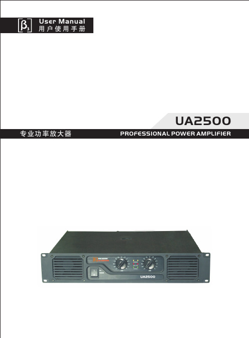
当您使用本公司的UA系列专业功率放大器之前,请认真阅读本手册,严格按照本手册的使用方法进行操作;如有疑问,请向当地特约代理商咨询或登陆本公司网站: 查询。
尊敬的用户:目录注意事项1、功能特点2、性能参数3、安装示意图4、面板介绍5、后板介绍6、电源要求7、输入/输出接口8、功能设置与信号线连接9、操作步骤10、面板指示灯概述11、保护功能概述12、常见故障与排除方法13、P1 P1 P2 P3 P4 P4 P5 P5 P6 P8 P8 P8 P9安全使用注意事项14、P10一、注意事项机内有高压,请不要打开外壳,维修请向专业人员咨询;请不要将本设备暴露在雨中或置于潮湿的地方;请注意通风良好,切勿堵住产品的通风口;请注意当地电网电压是否与产品电压相符;当长时间不使用本产品时,请将整机电源插头拔下;请配接额定负载,不要使机器长时间超负荷运行;标识解释:等边三角形内带有箭头的闪电标识,用于警告用户箱体内有可能给人带来电击危险的“危险电压”;等边三角形内的惊叹号代表产品宣传页上的重要操作步骤。
二、功能特点UA2500为高性能,大功率的专业放大器,能满足音频领域多样化的需求,它具备以下特点:1〉功率强劲,驱动能力极强;2〉采用了优化的散热器结构和高品质的散热风扇,使得长时间大功率工作得到了可靠保证;3〉“负载阻抗温度--功率--工作电压” 交互控制功能,风扇随机内温度变化而自动加速,当配接的负载 阻抗过低或温度过高时,机器会调整供电,降低电源内阻,可改善音质并有效地保护了机器,使可靠 性大大提高;4〉低失真;5〉高转换速率,音质更优美,清晰度更高;6〉低噪声:S/N>108dB(A);7〉频带宽 20Hz~20kHz <+0/-0.25 dB;8〉体积小,采用2U机箱结构设计;三、性能参数立体声模式单声道模式桥接模式<0.05%(10%额定功率)<0.1%(60Hz/7kHz,10%额定功率)短路、直流失调、过载、过热等四风扇、无级变速、气流由前向后冷却483×452×88mm 30kg220V/230V,50Hz/60Hz,1800VA ~,≤90%工作温度 -10℃~40℃ 储运温度 -25℃~80℃1V >100V/μs非平衡输入10kΩ,平衡输入20kΩ3脚XLR/6.35mm插座防碰触接线柱,NL4型并联/立体声/桥接选择、低切选择、接地选择、压限选择黄色-桥接、红色-过载、绿色-信号20Hz~20kHz(+0/-0.25dB)<±15°>800(8Ω/100Hz)>75dB >108dB(A计权)39±0.5dB <0.25dB 总谐波失真互调失真频率响应相移特性阻尼系数分离度信噪比整机增益输入灵敏度转换速率输入阻抗输入接口输出接口冷却方式前板控制后板控制前板指示功放保护机身尺寸机身重量电源要求环境湿度环境温度通道增益差交流电源开关、通道1和通道2增益控制旋钮8Ω8Ω16Ω1250W 1250W 2400W 2000W 2000W 3600W4Ω4Ω8Ω额定功率 1kHz四、安装示意图76.2m m446mm 441mm 435.7mm 430.5mm482.4m m465.0m m气流方向气流方向446m m425m m 433.0m m 87.9m m气流方向气流方向1、进风孔2、通道1信号指示3、通道1过载指示五、面板介绍UA SERIESPRO DESIGNUA2500B R I D G EP E A KS I G N A L-2-4-6-8-10-12-14-16-18-20-24-2-4-6-8-10-12-14-16-18-20-24CHBCHA POWERON 4、通道桥接指示 5、通道2过载指示6、通道2信号指示7、电源开关8、通道1增益调节电位器 9、通道2增益调节电位器123456789六、后板介绍CHA BRIDGE INCHB PIN1: SIGNAL GND PIN2: SIGNAL +PIN3: SIGNAL -BRIDGE PARALLEL STEREOMODELF FILTERGROUNDCLIPLIMITERON OFF50HZ 25HZ ONOFFCHB OUTPUTCHA OUTPUTPOWERCABLEFUSEINPUT-B+-A+-+5HZCAUTIONRISK OF ELECTRIC SHOCKDO NOT OPENB R I D G E!12345678910111213141、通道1信号输入(XLR插座)2、通道1信号输入(1/4″话筒插座)3、工作模式转换4、压限选择开关5、通道2信号输出(防碰触接线柱)6、通道1信号输出(防碰触接线柱)7、保险丝8、通道2信号输入(XLR插座)9、通道2信号输入(1/4话筒插座)10、滤波器选择开关11、接地开关12、通道1信号输出(NL4插座)13、通道2信号输出(NL4插座)14、电源线″RMS:STERO:8Ω 1000W ×2BRIDGE:16Ω 2000W OUTPUT ASSIGNMENT:BRIDGE MONO OUTPUT:CHA :PIN1+ : SIGNAL GNDCHA: 4Ω 1600W ×2 8Ω 3200WPIN 1+ :PIN 1 - :PIN 2+ :PIN 2 - : CHA SIGNALCHA GND CHB SIGNAL CHB GND CHB:PIN 1+ :PIN 1 - :PIN 2+ :PIN 2 - :CHB SIGNALCHB GND PIN2+ : Special design for big power !123123连接此功放到电源插座时,请确定当地电网电压与功放背板后的电压指示相同 (V~Hz/);连接此功放到电源插座时,确认插座未损坏,电源线无破损,关机后请将电源插头拔出。
2011 GM 2500HD 3500HD ReadyLift 抬高系统安装说明书

ReadyLift(Part# 66-3011)Leveling Kit Installation Instructions2011Up GM 2500HD/3500HD Truck 2WD/4WDSAFETY WARNING:ReadyLift Suspension Inc. recommends this system be installed by a professional techni-cian. In addition to these instructions, professional knowledge of disassembly/ reassembly procedures and post installation checks must be known.PRODUCT SAFETY WARNING:Modifying your vehicle ride height may result in the vehicle handling differ-ently than a factory equipped vehicle. Extreme care must be used to prevent loss of control or vehicle rollover. Failure to drive your modified vehicle safely may result in serious injury or death. ReadyLift Suspension Inc. does not recommend the combined use of suspension lifts, body lifts, or other lifting devices. You should never operate your modified vehicle under the influence of alcohol or drugs. Always drive your modified vehicle at reduced speeds to ensure your ability to control your vehicle under all driving conditions. Always wear your seat belt.Pre-Installation Notes1. Special literature required: OE Service Manual for model/year of vehicle. Refer to manual for proper disas-sembly/reassembly procedures of OE and related components.2. Adhere to recommendations when replacement fasteners, retainers and keepers are called out in the OE manual.3. Larger rim and tire combinations may increase leverage on suspension, steering, and related components. When selecting combinations larger than OE, consider the additional stress you could be inducing on the OE and related components.4. Post suspension system vehicles may experience drive line vibrations. Angles may require tuning, slider on shaft may require replacement, shafts may need to be lengthened or trued, and U-joints may need to be re-placed.5. Secure and properly block vehicle prior to installation of ReadyLift Suspension Inc. components. Always wear safety glasses when using power tools.6. If installation is to be performed without a hoist, ReadyLift Suspension Inc. recommends rear alterations first.7. Due to payload options and initial ride height variances, the amount of lift is a base figure. Final ride height dimensions may vary in accordance to original vehicle attitude. Always measure the attitude prior to beginning installation.POST-INSTALLATION WARNINGS1. Check all fasteners for proper torque. Check to ensure for adequate clearance between all rotating, mobile, fixed, and heated members. Verify clearance between exhaust and brake lines, fuel lines, fuel tank, floor boards and wiring harness. Check steering gear for clearance. Test and inspect brake system.2. Perform steering sweep to ensure front brake hoses have adequate slack and do not contact any rotating, mobile or heated members. Inspect rear brake hoses at full extension for adequate slack. Failure to perform hose check/ replacement may result in component failure. Longer replacement hoses, if needed can be pur-chased from a local parts supplier.3. Headlight adjustment is highly recommended.4. Re-torque all fasteners after 500 miles. Always inspect fasteners and components during routine servicing.ReadyLift(Part# 66-3011)Leveling Kit Installation Instructions2011-Up GM 2500HD/3500HD Truck 2WD/4WDTake your initial measurements.DF_______ PF_______ DR_______ PR_______ You will need ReadyLift part# 66-7816A to remove your fac-tory keys and install the new ReadyLift keys.Install the tool and load up torsion key until adjuster block is Remove the torsion key adjusting bolt,ReadyLift (Part# 66-3011) Leveling Kit Installation Instructions2011-Up GM 2500HD/3500HD Truck 2WD/4WDInstall new ReadyLift 66-3011 forged torsion key in the reverseorder as the OE key was removed. Note: new key will hangdown slightly lower than the original key.Reinstall torsion key loading tool and tighten until adjusterblock can be reinstalled into subframe, note fig. 5.Once seated properly, unload torsion key tool and install ad-justing bolt. Final adjustment will be made once aligned, meanwhile, adjust to approximate desired height. At the top of the front shock behind wheel well flap, loosen and remove upper shock mounting nuts.7.10.9.8.Now remove adjuster block from subframe. Loosen torsion bar unloading tool.With a drift or appropriate tool, tap torsion bar forward out of torsion key. Use caution, as key will fall out, while removing OE torsion key.5.6.ReadyLift (Part# 66-3011) Leveling Kit Installation Instructions2011-Up GM 2500HD/3500HD Truck 2WD/4WDReinstall shock into factory position and tighten to factory specwith provided M12-1.75 serrated nuts.Allow wheel well flap to rest as original. Reinstall wheels andtires, torque to factory specs and align.13. 14.Use a pry bar to push down shock out of mount.Place shock extension spacers, (2) per side, onto upper shock mounting studs.11.12.ReadyLift (Part# 66-3011) Leveling Kit Installation Instructions2011-Up GM 2500HD/3500HD Truck 2WD/4WDWarning!This ReadyLift ® 66-3011 Kit is designed and engineered to lift a stock vehi-cle with no prior modifications. The use of this kit along with items such as rear lift Installation WarningAlways wear proper safety equipment and use the correct tools when installing any suspension up-grade. Make sure vehicle is on a flat surface and you are using jack stands or a lift rated for the weight of the vehicle.Vehicle Handling WarningVehicles with larger wheels and tires will handle differently than stock vehicles.Take time to familiarize yourself with the handling of your vehicle.DRIVE SAFELY & WEAR YOUR SEATBELT.。
安德里茨设备操作,安装,维修手册
Before opening the cover of the screen: make sure that the screen is de pressurized make sure that no liquid or stock can flow into the screen
The screen can be started after maintenance only after: the cover of the screen has been closed all original guards have been installed properly The sealing water valve must be opened before starting the drive motor of the screen!
SPC
Smaller pulley, 160-224 236-315 224-355 375-560
mm
F (N) 35-50 50-65 60-90 90-120
Belt deflection
Equipment F10 F20 F30 F40 F50 F60
Deflection (mm) 15 15 20 20 25 32
Operation, Installation and Maintenance Manual
Piping and Valve installation
General instructions for installation Pipes should be supported in such a way that the weight of the pipes is not taken by the screen In locating the supports, take care to ensure that the pipes do not cause stress to the screen The supports must allow for thermal expansion of the pipes If not, connections and screen body will be damaged! Piping Feed, accept, reject, reject dilution, rotor dilution, sealwater, deaeration, junk trap, emptying/flushing
Philips AEA2500 Bluetooth 配对指南说明书
User manual 用户手册Question?Contact Philipsto switch to the pairing mode.Blue light flashes.press , AEA2500 connects to the If your Bluetooth device supports NFC (Near Field Communication),ENSpecificationsAmplifier• Output Voltage: 1000 mV RMS• Signal to Noise Ratio: > 62 dBA• T otal Harmonic Distortion: < 2 %Bluetooth• Standard: Bluetooth Standard Version 3.0 • Frequency band: 2.402 ~ 2.480 GHz ISM Band • Range: 10 m (free space)General information• Power supplyAC/DC adapterAS030-090-EB033(Philips)Input:100-240 V~ 50/60 Hz,0.15 AOutput:9 V DC,0.33 A• Power consumption Operation:< 3 W • DimensionsMain Unit (W x H x D):74 x 28 x 72 mm • WeightMain Unit:0.04 kg中文规格功放器• 输出电压:1000 毫伏 RMS• 信噪比:> 62 dBA • 总谐波失真:< 2 %蓝牙• 标准:蓝牙标准版本 3.0• 频段:2.402 ~ 2.480 GHz ISM 频段• 范围:10 米(开阔空间)一般信息• 电源交流/直流适配器AS030-090-EB033(飞利浦)输入:约 100-240 伏 50/60 赫兹,0.15 安输出:直流 9 伏,0.33 安• 功耗工作:< 3 瓦• 尺寸主装置(宽 x 高 x 深):74 x 28 x 72 毫米• 重量主装置:0.04千克ImportantSafetyRead these instructions.Follow all instructions.Do not use this apparatus near water.Do not place near any heat sources such as radiators,heat registers,stoves,or other apparatus (including amplifiers) that produce heat.Protect the power cord from being walked on or pinched,particularly at plugs,convenience receptacles,and the point wherethey exit from the apparatus.Only use attachments/accessories specified by the manufacturer.Use only power supplies listed in the user manual.The product shall not be exposed to dripping or splashing.Do not place any sources of danger on the product (e.g.liquid filledobjects,lighted candles).Where the plug of the Direct Plug-in Adapter is used as thedisconnect device,the disconnect device shall remain readilyoperable.Warning•Never remove the casing of this apparatus.•Never lubricate any part of this apparatus.•Never place this apparatus on other electrical equipment.•Keep this apparatus away from direct sunlight,naked flames or heat.•Ensure that you always have easy access to the power cord,plug oradaptor to disconnect the apparatus from the power.ComplianceNote•The type plate is located on the bottom of the product.Care of the environmentEnvironmental informationAll unnecessary packaging has been omitted.We have tried tomake the packaging easy to separate into three materials:cardboard(box),polystyrene foam (buffer) and polyethylene (bags,protectivefoam sheet.)Y our system consists of materials which can be recycled and reusedif disassembled by a specialized company.Please observe the localregulations regarding the disposal of packaging materials,and oldequipment.RecyclingY our product is designed and manufactured with high qualitymaterials and components,which can be recycled and reused.Never dispose of your product with other householdwaste.Please inform yourself about the local rules on the separatecollection of electrical and electronic products.The correctdisposal of your old product helps prevent potentially negativeconsequences on the environment and human health.NoticeThe Bluetooth® word mark and logos areregistered trademarks owned by Bluetooth SIG,Inc.and any use of such marks by WOOX Innovations isunder license.© 2013 CSR plc and its group companies.The aptX® mark and the aptX logo are trade marksof CSR plc or one of its group companies and may be registered in one or more jurisdictions.The N Mark is a trademark or registered trademarkof NFC Forum,Inc.in the United States and in other countries.Specifications are subject to change without notice.Philips and the Philips’Shield Emblem are registered trademarks of Koninklijke Philips N.V.and are used by WOOX Innovations Limited under license from Koninklijke Philips N.V..WOOX Innovations reserves the right to change products at any time without being obliged to adjust earlier supplies accordingly.注意事项安全阅读这些说明。
- 1、下载文档前请自行甄别文档内容的完整性,平台不提供额外的编辑、内容补充、找答案等附加服务。
- 2、"仅部分预览"的文档,不可在线预览部分如存在完整性等问题,可反馈申请退款(可完整预览的文档不适用该条件!)。
- 3、如文档侵犯您的权益,请联系客服反馈,我们会尽快为您处理(人工客服工作时间:9:00-18:30)。
1系统设置1.1Resource Manager管理1、安装Hitachi Resource Manager2(Storage Navigator Modular2)将Hitachi Resource Manager2 光盘放入CDROM驱动器,运行光盘上windows目录中的setup.exe文件,按照提示安装Resource Manager 软件。
2、配置/管理Hitachi source Manager使用IE,进入地址:http://localhost:23015/StorageNavigatorModular/Login1.输入User Id/Password进入,进行管理2.在下图Storage Navigator Modular2在添加AMS存储的信息3.进入设备的初期信息修改向导4.设置E-mail提醒(如果不用,请设为Disable):5.修改管理端口的IP地址:6.修改前端端口属性(连接交换机要改为P2P,直联使用Loop):7.修改系统时间:8.各项确认:9.添加完毕后出现的管理窗口如下:10.设置Spare盘11.创建Raid组12. 创建Lun13. 打开Host Group Security 参数14.添加HostGrop15.创建主机WWN映射16.映射Lun17.修改主机平台18.添加WWN别名。
2主机识别硬盘,HDLM安装及设置2.1存储参数设置2.2主机识别硬盘及HDLM安装2.2.1安装AIX_ODM1)进入AIX_ODM所在的目录,分别按照下列顺序安装其中的软件:#cd V5.0.0.1#smitty install_latest#cd V5.0.0.4U#smitty install_latest#cd V5.0.1.4U#smitty install_latest#cd V5.0.52.1U#smitty install_latest2.2.2安装HDLM软件从光盘上拷贝*.plk至/var/tmp/hdlm_licenseInstall SoftwareType or select values in entry fields.Press Enter AFTER making all desired changes.[Entry Fields]* INPUT device / directory for software /dev/cd0* SOFTWARE to install [_all_latest] + PREVIEW only? (install operation will NOT occur) no + COMMIT software updates? yes + SA VE replaced files? no + AUTOMATICALL Y install requisite software? yes + EXTEND file systems if space needed? yes + OVERWRITE same or newer versions? no + VERIFY install and check file sizes? no + Include corresponding LANGUAGE filesets? yes + DETAILED output? no + Process multiple volumes? yes + ACCEPT new license agreements? yes +Preview new LICENSE agreements? no +F1=Help F2=Refresh F3=Cancel F4=ListEsc+5=Reset Esc+6=Command Esc+7=Edit Esc+8=ImageEsc+9=Shell Esc+0=Exit Enter=Do2.2.3打Sp1补丁1)执行# lslpp -la DLManager.mpio.rte命令,确保文件DLManager.mpio.rte被安装。
Fileset Level State Description---------------------------------------------------------------------------Path: /usr/lib/objreposDLManager.mpio.rte 6.1.0.0 COMMITTED Dynamic Link ManagerPath: /etc/objreposDLManager.mpio.rte 6.1.0.0 COMMITTED Dynamic Link Manager2)删除hdlm管理设备,执行# /usr/DynamicLinkManager/bin/dlmrmdev命令。
3)安装补丁:# installp -acXgd directory-storing-copied-installation-file all(请指向SP光盘中的文件解压)4)验证:# lslpp -la DLManager.mpio.rteFileset Level State Description---------------------------------------------------------------------------Path: /usr/lib/objreposDLManager.mpio.rte 6.1.0.0 COMMITTED Dynamic Link Manager6.1.0.1 COMMITTED Dynamic Link ManagerPath: /etc/objreposDLManager.mpio.rte 6.1.0.0 COMMITTED Dynamic Link Manager2.2.4识别设备删除原来识别出的设备:rmdev -dl fcs0 -Rrmdev -dl fcs1 –R重新识别出新设备:cfgmgr –v修改设备参数# rmdev -l fscsi0 –R# rmdev -l fscsi1 –R# chdev -l fscsi0 -a fc_err_recov=fast_fail# chdev -l fscsi1 -a fc_err_recov=fast_fail#cfgmgr –v2.3 Adding Custom Disk Methods1. From the SMIT window, display the Add Custom Disk Methods window. Choose the following sequence of menu items to display this window: Communications Applications and Services, HACMP for AIX,Extended Configuration, Extended Resource Configuration, HACMPExtended Resource Configuration, Configure Custom Disk Methods,and finally choose Add Custom Disk Methods.2. In the Add Custom Disk Methods window, specify the items as shown below:The items to be set and setting contents are shown below:–When a Fibre Channel connection is used with HACMPChange the custom disk method settings as described below. The description includes information about the items and contents of the settings.Disk Type (PdDvLn field from CuDv)•When a Hitachi AMS2000/AMS/WMS/SMS series is used:disk/fcp/HitachiMethod to identify ghost disksSCSI3Method to determine if a reserve is held/usr/DynamicLinkManager/cluster/dlm_hacmp_gdisk_reserve_checkMethod to break a reserveTARGETBreak reserves in parallelfalseMethod to make the disk availableMKDEV3. When you finish specifying the settings, click the OK button.4. From the SMIT window, display the Single Select List window.Choose the following sequence of menu items to display this window: Communications Applications and Services, HACMP for AIX,Extended Configuration, and finally choose Extended Verification and Synchronization.2.4 Setting the Reservation PolicyWhen you use HACMP, we usually recommend that you set thereserve_policy attribute to PR_exclusive. However, when a virtual I/Ofunction is applied in order to use HACMP in a client partition, use the following procedure to check, in the virtual I/O server partition, the settingsfor the reserve_policy attribute of the hdisk. If reserve_policy is set toPR_exclusive, change its value to no_reserve.1. Check the setting for the reserve_policy attribute of the hdisk.# lsattr -El hdisk n -a reserve_policyreserve_policy PR_exclusive N/A TRUEPerform the following steps if reserve_policy is set to PR_exclusive:2. Quit all applications that specify and directly access the hdisk whose attribute is to be changed.3. Execute the following command to unmount the file system used by HDLM.# umount file-system-mount-point4. Execute the following command to display all the activated volume groups.# lsvg -o5. Among the displayed volume groups, inactivate the volume groups used by HDLM.# varyoffvg volume-group-name6. Execute the chdev command to change the reserve_policy attribute tono_reserve.# chdev -l hdisk n -a reserve_policy=no_reserve7. Confirm that the setting was changed to no_reserve.# lsattr -El hdisk n -a reserve_policyreserve_policy no_reserve N/A TRUE。
