青岛海尔空调Hair(三菱重工)1台协议调试手册
三菱重工 天花板吊挂式空调器 50HZ 3D 变频控制 技术手册说明书
TM_FLOOR CEILING_50R32_3D INVERTER_EU_S_NA_1905 FLOOR CEILINGR32 50HZ 3D INVERTER CONTROL TECHNICAL MANUALTable of Contents Page1. Specifications (4)1. Model Reference2. General Specifications3. Dimensional Drawings4. Centre of Gravity5. Electrical Wiring Diagrams6 Refrigerant Cycle Diagrams7. Capacity Tables8. Capacity Correction Factor for Height Difference9. Noise Criterion Curves10. Electrical Characteristics2. Product Features (74)1. Operation Modes and Functions2. Remote Controller Functions3. Installation (93)1. Installation Overview2. Location Selection3. Indoor Unit Installation4. Outdoor Unit Installation5. Drainage Pipe Installation6. Refrigerant Pipe Installation7. Vacuum Drying and Leakage checking8. Additional Refrigerant ChargeTable of Contents Page9. Engineering of Insulation10. Engineering of Electrical Wiring11. Test OperationContents1. Model Reference (5)2. General Specifications (6)3. Dimensional Drawings (12)4. Centre of Gravity (15)5. Electrical Wiring Diagrams (19)6 Refrigerant Cycle Diagrams (33)7. Capacity Tables (36)8. Capacity Correction Factor for Height Difference (60)9. N oiseCriterion Curves (67)10. Electrical Characteristics (73)S p e c i fi c a t i o n s③ Page 5 ④1. Model ReferenceRefer to the following table to determine the specific indoor and outdoor unit model number of your purchasedequipment.2. General SpecificationsIndoor model MUE-18HRFNX-QRD0MUE-24HRFNX-QRD0MUE-36HRFNX-QRD0Outdoor model MOB30U-18HFN8-QRD0MOCA30U-24HFN8-QRD0MOD30U-36HFN8-QRD0 Power supply (Indoor )V- Ph-Hz220~240-1-50220~240-1-50220~240-1-50Power Supply (Outdoor)V-Ph-Hz220~240-1-50220~240-1-50220~240-1-50Max. input consumption W220029504700 Max. current A10.013.521.5Indoor fan motorModel ZKFN-55-8-1ZKFN-55-8-1ZKFN-90-8-1 Qty112 Insulation class E E E IP rating IPX4IPX4IPX4 Input W100.0100.096.0 Capacitor uF/// Speed(Hi/Mi/Lo)r/min950/850/7501200/1080/8901200/1050/850Indoor coilNumber of rows 3.0 3.03 Tube pitch(a)x row pitch(b) mm21x13.3721x13.3721x13.37 Fin spacing mm 1.3 1.3 1.3Fin type (code)Hydrophilic aluminum Hydrophilic aluminum Hydrophilic aluminum Tube outside dia.and type mmΦ7,Inner groove tubeΦ7,Inner groove tubeΦ7,Inner groove tube Coil length x height x width mm795x294x40.11795x294x40.111300x294x40.11 Number of circuits778Indoor air flow (Hi/Mi/Lo)m3/h902/786/6771208/1066/8532160/1844/1431 Indoor sound pressure level dB(A)45/40/3749/46/4150/46/42 Indoor sound power level dB(A)566161Indoor unitDimension(W*D*H)mm1068x675x2351068x675x2351650x675x235 Packing (W*D*H)mm1145x755x3131145x755x3131725x755x313 Net/Gross weight Kg26.6/31.826.8/31.941.5/48 Design pressure MPa 4.2/1.5 4.2/1.5 4.2/1.5Drainage water pipe diameter mm ODΦ25mm ODΦ25mm ODΦ25mm Refrigerant piping Liquid side/ Gas side mm(inch)Φ6.35/Φ12.7(1/4"/1/2")Φ9.52/Φ15.9(3/8"/5/8")Φ9.52/Φ15.9(3/8"/5/8") Controller Remote contorl Remote contorl Remote contorl Operation temperature°C17-3017-3017-30Room temperature Cooling°C17~3217~3217~32 Heating°C0~300~300~30Qty’per 20’ /40’ /40’HQ Indoor unit102/220/252102/220/25272/147/167CompressorModel KSM135D23UFZ KTF235D22UMT KTF310D43UMT Type ROTARY ROTARY ROTARY Brand GMCC GMCC GMCC Capacity W4230765010010 Input W108020652765 Rated current(RLA) A7.19.4 5.38 Refrigerant oil/oil charge ml VG74/450RB74A F/670VG74/1000Outdoor fan motorModel ZKFN-40-8-1L ZKFN-50-8-2ZKFN-120-8-2 Qty 111 Insulation class E E E IP rating IPX4IPX0IPX4 Output W63.0115.0150.0 Capacitor uF/// Speed r/min8108501050③ Page 6 ④i i ③ Page 7 ④Outdoor coilNumber of rows 2.0 2.0 2.0Tube pitch(a)x row pitch(b)mm 25.4x2225.4x2225.4x22Fin spacingmm1.41.41.3Fin type (code)Hydrophilic aluminum Hydrophilic aluminum Hydrophilic aluminum Tube outside dia.and type mm Φ9.52,Inner groove tubeΦ9.52,Inner groove tubeΦ9.52,Inner groove tubeCoil length x height x widthmm 860x508x44730x660x44995x762x44Number of circuits444Outdoor air flow m3/h 210027004000Outdoor sound pressure level dB(A)555963Outdoor sound power leveldB(A)636567Throttle typeEXV+Capillary EXV+Capillary EXV+Capillary Outdoor unitDimension(W*D*H)mm 800x333x554845x363x702946x410x810Packing (W*D*H)mm 920x390x615965x395x7651090x500x875Net/Gross weightKg 35.6/38.549.4/52.866.8/73.4Refrigerant typeType-R32R32R32GWP -675675675Charged quantityKg 1.35 1.5 2.4Design pressureMPa 4.2/1.54.2/1.54.2/1.5Refrigerant pipingLiquid side/ Gas sidemm(inch)Φ6.35/Φ12.7(1/4"/1/2")Φ9.52/Φ15.9(3/8"/5/8")Φ9.52/Φ15.9(3/8"/5/8")Max. refrigerant pipe length m 305065Max. difference in levelm 202530Ambient temperatureCooling °C -15~50-15~50-15~50Heating°C -15~24-15~24-15~24Qty’per 20’ /40’ /40’HQOutdoor unit108/219/292102/215/21644/96/144Notes:1) Capacities are based on the following conditions:Cooling(T1): - Indoor Temperature 27°C(80.6°F) DB /19 °C(66.2°F) WB Heating: - Indoor Temperature 20°C(68°F) DB / 15°C(59°F) WB -Outdoor Temperature 35 °C(95°F) DB /24 °C(75.2°F) WB -Outdoor Temperature 7°C(44.6°F) DB / 6°C(42.8°F) WB -Interconnecting Piping Length 5m - Interconnecting Piping Length 5 m - Level Difference of Zero. - Level Difference of Zero.2) Capacities are Net Capacities.3) Due to our policy of innovation some specifications may be changed without notification.Indoor model MUE-30HRFNX-QRD0MUE-42HRFNX-QRD0Outdoor model MOD30U-30HFN8-QRD0MOD30U-42HFN8-QRD0 Power supply (Indoor )V- Ph-Hz220~240-1-50220~240-1-50 Power Supply (Outdoor)V-Ph-Hz220~240-1-50220~240-1-50 Max. input consumption W36004800 Max. current A16.522.5Indoor fan motorModel ZKFN-90-8-1ZKFN-90-8-1 Qty22 Insulation class E E IP rating IPX4IPX4 Input W96.096.0 Capacitor uF// Speed(Hi/Mi/Lo)r/min1200/1050/8501300/1100/850Indoor coilNumber of rows33 Tube pitch(a)x row pitch(b) mm21x13.3721x13.37 Fin spacing mm 1.3 1.3Fin type (code)Hydrophilic aluminum Hydrophilic aluminum Tube outside dia.and type mmΦ7,Inner groove tubeΦ7,Inner groove tube Coil length x height x width mm1300x294x40.111300x294x40.11 Number of circuits88Indoor air flow (Hi/Mi/Lo)m3/h2160/1844/14312329/1930/1417 Indoor sound pressure level dB(A)50/46/4254/50/46 Indoor sound power level dB(A)6266Indoor unitDimension(W*D*H)mm1650x675x2351650x675x235Packing (W*D*H)mm1725x755x3131725x755x313Net/Gross weight Kg41.5/4841.2/47.6 Design pressure MPa 4.2/1.5 4.2/1.5 Drainage water pipe diameter mm ODΦ25mm ODΦ25mmRefrigerant piping Liquid side/ Gas side mm(inch)Φ9.52/Φ15.9(3/8"/5/8")Φ9.52/Φ15.9(3/8"/5/8") Controller Remote contorl Remote contorl Operation temperature°C17-3017-30Room temperatureCooling°C17~3217~32Heating°C0~300~30 Qty’per 20’ /40’ /40’HQ Indoor unit72/147/16772/147/167CompressorModel KTM240D57UMT KTF310D43UMT Type ROTARY ROTARY Brand GMCC GMCC Capacity W7715 10010Input W2085 2765 Rated current(RLA) A9 5.38 Refrigerant oil/oil charge ml VG74/670VG74/1000Outdoor fan motorModel ZKFN-120-8-2ZKFN-120-8-2 Qty 1 1 Insulation class E E IP rating IPX4IPX4 Output W150.0150.0 Capacitor uF// Speed r/min1050/900/8501050/900/850③ Page 8 ④i i ③ Page 9 ④Outdoor coilNumber of rows 1.6 2.6Tube pitch(a)x row pitch(b)mm 25.4x2225.4x22Fin spacingmm1.51.5Fin type (code)Hydrophilic aluminum Hydrophilic aluminum Tube outside dia.and type mm Φ9.52,Inner groove tube Φ9.52,Inner groove tubeCoil length x height x widthmm 1005x762x22+580x762x22995x762x22+960x762x22+580x762x22Number of circuits46Outdoor air flow m3/h 38003600Outdoor sound pressure level dB(A)58.565Outdoor sound power leveldB(A)6772Throttle typeEXV+Capillary EXV+Capillary Outdoor unitDimension(W*D*H)mm 946x410x810946x410x810Packing (W*D*H)mm 1090x500x8851090x500x885Net/Gross weightKg 56.9/61.873.9/78.9Refrigerant typeType-R32R32GWP -675675Charged quantityKg 2.0 2.8Design pressureMPa 4.3/1.74.3/1.7Refrigerant pipingLiquid side/ Gas sidemm(inch)Φ9.52/Φ15.9(3/8"/5/8")Φ9.52/Φ15.9(3/8"/5/8")Max. refrigerant pipe length m 5065Max. difference in levelm 2530Ambient temperatureCooling °C -15~50-15~50Heating°C -15~24-15~24Qty’per 20’ /40’ /40’HQOutdoor unit44/96/13844/96/138Notes:1) Capacities are based on the following conditions:Cooling(T1): - Indoor Temperature 27°C(80.6°F) DB /19 °C(66.2°F) WB Heating: - Indoor Temperature 20°C(68°F) DB / 15°C(59°F) WB -Outdoor Temperature 35 °C(95°F) DB /24 °C(75.2°F) WB -Outdoor Temperature 7°C(44.6°F) DB / 6°C(42.8°F) WB -Interconnecting Piping Length 5m - Interconnecting Piping Length 5 m - Level Difference of Zero. - Level Difference of Zero.2) Capacities are Net Capacities.3) Due to our policy of innovation some specifications may be changed without notification.Indoor model MUE-36HRFNX-QRD0MUE-48HRFNX-QRD0MUE-55HRFNX-QRD0 Outdoor model MOD30U-36HFN8-RRD0MOE30U-48HFN8-RRD0MOE30U-55HFN8-RRD0 Power supply (Indoor )V- Ph-Hz220~240-1-50220~240-1-50220~240-1-50 Power Supply (Outdoor)V-Ph-Hz380~415-3-50380~415-3-50380~415-3-50 Max. input consumption W560062007500 Max. current A10.011.214Indoor fan motorModel ZKFN-90-8-1ZKFN-90-8-1ZKFN-160-8-1-2 Qty222 Insulation class E E E IP rating IPX4IPX4IPX0 Input W96.096.090.0 Capacitor uF/// Speed(Hi/Mi/Lo)r/min1200/1050/8501300/1100/8501350/1050/850Indoor coilNumber of rows333 Tube pitch(a)x row pitch(b) mm21x13.3721x13.3721x13.37 Fin spacing mm 1.3 1.3 1.3Fin type (code)Hydrophilic aluminum Hydrophilic aluminum Hydrophilic aluminum Tube outside dia.and type mmΦ7,Inner groove tubeΦ7,Inner groove tubeΦ7,Inner groove tube Coil length x height x width mm1300x294x40.111300x294x40.111300x294x40.11 Number of circuits888Indoor air flow (Hi/Mi/Lo)m3/h2160/1844/14312329/1930/14172454/1834/1426 Indoor sound pressure level dB(A)50/46/4054/50/4654/47/42 Indoor sound power level dB(A)596669Indoor unitDimension(W*D*H)mm1650x675x2351650x675x2351650x675x235 Packing (W*D*H)mm1725x755x3131725x755x3131725x755x313 Net/Gross weight Kg41.5/4841.2/47.641.4/47.8 Design pressure MPa 4.2/1.5 4.2/1.5 4.2/1.5Drainage water pipe diameter mm ODΦ25mm ODΦ25mm ODΦ25mm Refrigerant piping Liquid side/ Gas side mm(inch)Φ9.52/Φ15.9(3/8"/5/8")Φ9.52/Φ15.9(3/8"/5/8")Φ9.52/Φ15.9(3/8"/5/8") Controller Remote contorl Remote contorl Remote contorl Operation temperature°C17-3017-3017-30Room temperature Cooling°C17~3217~3217~32 Heating°C0~300~300~30Qty’per 20’ /40’ /40’HQ Indoor unit72/147/16772/147/16772/147/167CompressorModel KTF310D43UMT KTQ420D1UMU KTQ420D1UMU Type ROTARY ROTARY ROTARY Brand GMCC GMCC GMCC Capacity W100101370013700 Input W276537003700 Rated current(RLA) A 5.387.027.02 Refrigerant oil/oil charge ml VG74/1000VG74/1400VG74/1400Outdoor fan motorModel ZKFN-120-8-2ZKFN-85-8-22ZKFN-85-8-22-2 Qty 122 Insulation class E E E IP rating IPX4IPX4IPX4 Output W150.0126.0126.0 Capacitor uF/// Speed r/min1050850850③ Page 10 ④i i Outdoor coilNumber of rows 2.0 1.6 2.0Tube pitch(a)x row pitch(b)mm 25.4x2225.4x2225.4x22Fin spacingmm1.31.41.4Fin type (code)Hydrophilic aluminum Hydrophilic aluminum Hydrophilic aluminum Tube outside dia.and type mm Φ9.52,Inner groove tubeΦ9.52,Inner groove tube Φ9.52,Inner groove tubeCoil length x height x widthmm 995x762x44990x1270x22+500x1270x22990x1270x44Number of circuits488Outdoor air flow m3/h 400075007500Outdoor sound pressure level dB(A)616665Outdoor sound power leveldB(A)667274Throttle typeEXV+Capillary EXV+Capillary EXV+Capillary Outdoor unitDimension(W*D*H)mm 946x410x810952x415x1333952x415x1333Packing (W*D*H)mm 1090x500x8751095x495x14801095x495x1480Net/Gross weightKg 81.5/87.0106.7/119.9111.3/124.3Refrigerant typeType-R32R32R32GWP -675675675Charged quantityKg 2.4 2.8 2.95Design pressureMPa 4.2/1.54.2/1.54.2/1.5Refrigerant pipingLiquid side/ Gas sidemm(inch)Φ9.52/Φ15.9(3/8"/5/8")Φ9.52/Φ15.9(3/8"/5/8")Φ9.52/Φ15.9(3/8"/5/8")Max. refrigerant pipe length m 656565Max. difference in levelm 303030Ambient temperatureCooling °C -15~50-15~50-15~50Heating°C -15~24-15~24-15~24Qty’per 20’ /40’ /40’HQOutdoor unit44/96/14422/48/4822/48/48Notes:1) Capacities are based on the following conditions:Cooling(T1): - Indoor Temperature 27°C(80.6°F) DB /19 °C(66.2°F) WB Heating: - Indoor Temperature 20°C(68°F) DB / 15°C(59°F) WB -Outdoor Temperature 35 °C(95°F) DB /24 °C(75.2°F) WB -Outdoor Temperature 7°C(44.6°F) DB / 6°C(42.8°F) WB -Interconnecting Piping Length 5m - Interconnecting Piping Length 5 m - Level Difference of Zero. - Level Difference of Zero.2) Capacities are Net Capacities.3) Due to our policy of innovation some specifications may be changed without notification.3. Dimensional Drawings3.1 Indoor UnitModel(KBtu/h)Unit A B C D18-24mm1068675235983 inch42.0526.579.2538.730-60mm16506752351565 inch64.9626.579.2561.61S p e c i fi c a t i o n s3.2 Outdoor UnitSingle Fan Outdoor UnitDouble Fan Outdoor UnitS p e c i fi c a t i o n s4. Centre of gravityMOB30U-18HFN8-QRD0MOCA30U-24HFN8-QRD0MOD30U-30HFN8-QRD0, MOD30U-36HFN8-QRD0, MOD30U-36HFN8-RRD0, MOD30U-42HFN8-QRD0S p e c i fi c a t i o n sMOE30U-48HFN8-RRD0, MOE30U-55HFN8-RRD05. Electrical Wiring Diagrams 5.1 Indoor unitS p e c i fi c a t i o n sMUE-18HRFNX-QRD0, MUE-24HRFNX-QRD0MUE-30HRFNX-QRD0, MUE-36HRFNX-QRD0, MUE-42HRFNX-QRD0, MUE-48HRFNX-QRD0, MUE-55HRFNX-QRD0S p e c i fi c a t i o n s5.2Some connectors introduce:A For remote control (ON-OFF) terminal port CN231. Remove the short connector in CN23 when you use ON-OFF function;2. When remote switch off (OPEN), the unit would be off;3. When remote switch on (CLOSE), the unit would be on;4. When close/open the remote switch, the unit would be responded the demand within 2 seconds;5. When the remote switch on. You can use remote controller/wire controller to select the mode what you want; when the remote switch off, the unit would not respond the demand from remote controller/wire controller.When the remote switch off, but the remote controller/wire controller are on, CP code would be shown on the display board.6. The voltage of the port is 12V DC, design Max. current is 5mA.B For ALARM terminal port CN33.1. Provide the terminal port to connect ALARM, but no voltage of the terminal port , the power from the ALARM system (not from the unit).2. Although design voltage can support higher voltage, but we strongly ask you connect the power less than 24V, current less than 0.5A.3. When the unit occurs the problem, the relay would be closed, then ALARM works.S p e c i fi c a t i o n sC. For new fresh motor terminal port CN14&CN14.1. Connect the fan motor to the port, no need care L/N of the motor;2. The output voltage is the power supply;3. The fresh motor cannot excess 200W or 1A, follow the smaller one;4. The new fresh motor will be worked when the indoor fan motor work ;when the indoor fan mo-tor stops, the new fresh motor would be stopped;5. When the unit enter force cooling mode or capacity testing mode, the fresh motor isn’t work.5.3Micro-Switch Introduce:A. Micro-switch SW1 is for setting the master or slave unit when the unit is in twin connection.Range: Master no slave (Normal 1 drive 1 connection), Master (2 positions without difference), SlaveB. Micro-switch SW2 is for selection of indoor FAN ACTION if room temperature reaches the setponit and the compressor stops.Range: OFF (in 127s), Keep running.C. Micro-switch SW3 is for selection of auto-restart function.Range: Active, inactiveD. Micro-switch SW4 is for selection of quantity of fan motors. Same as size selection switch, this switch is for making the PCB suitable for all series units. DO NOT change it at random unless you want to use the PCB as a spare part Range: Single Fan, Double FanS p e c i fi c a t i o n sE.Micro-switch SW6 is for selection of temperature compensation in heating mode. This helps to reduce the realtemperature difference between ceiling and floor so that the unit could run properly. If the unit is on-floor installed, 0 should be chosen.Range: 0°C, 2°C, 4°C, E function (reserved for special customizing)F . Micro-switch S1 and dial-switch S2 are for address setting when you want to control this unit by a central controller.Range: 00-63G. Dial-switch ENC1: The indoor PCB is universal designed for whole series units from 18K to 55K. This ENC1 setting will tell the main program what size the unit is.NOTE: Usually there is glue on it because the switch position cannot be changed at random unless you want to use this PCB as a spare part to use in another unit. Then you have to select the right position to match the size of the unit.“53” means 5.3kW (18K),“105” means 10.5kW(36K), and so on.5.4 Outdoor UnitS p e c i fi c a t i o n sMOB30U-18HFN8-QRD0MOCA30U-24HFN8-QRD0MOD30U-30HFN8-QRD0S p e c i fi c a t i o n sMOD30U-36HFN8-QRD0MOD30U-36HFN8-RRD0S p e c i fi c a t i o n sMOD30U-42HFN8-QRD0MOE30U-48HFN8-RRD0, MOE30U-55HFN8-RRD0S p e c i fi c a t i o n s6. Refrigerant Cycle Diagrams6.1Heat pumpS p e c i fi c a t i o n s7. Capacity Tables7.1 CoolingMUE-18HRFNX-QRD0+MOB30U-18HFN8-QRD0INDOOR AIRFLOW (CMH)OUTDOORDB(℃)ID WB(℃)16.018.019.022.0ID DB(℃)23.025.027.030.023.025.027.030.023.025.027.030.023.025.027.030.067727TC 5.1 5.1 5.1 5.2 5.3 5.3 5.3 5.4 5.5 5.5 5.5 5.5 5.9 5.9 5.9 5.9 S/T0.68 0.80 0.88 1.00 0.57 0.69 0.76 0.88 0.50 0.62 0.69 0.81 0.35 0.45 0.51 0.63 PI 1.39 1.39 1.39 1.39 1.39 1.39 1.39 1.39 1.39 1.39 1.39 1.39 1.39 1.39 1.39 1.39 30TC 5.0 5.0 5.0 5.1 5.2 5.2 5.2 5.2 5.3 5.3 5.3 5.3 5.7 5.7 5.7 5.7 S/T0.69 0.81 0.88 1.00 0.58 0.69 0.77 0.90 0.51 0.62 0.69 0.82 0.34 0.45 0.52 0.64 PI 1.46 1.46 1.46 1.46 1.46 1.46 1.46 1.46 1.47 1.47 1.47 1.47 1.47 1.47 1.47 1.47 32TC 4.9 4.9 4.9 5.0 5.1 5.1 5.1 5.1 5.2 5.2 5.2 5.2 5.7 5.7 5.7 5.7 S/T0.69 0.82 0.89 1.00 0.58 0.70 0.77 0.91 0.51 0.62 0.69 0.83 0.34 0.45 0.52 0.64 PI 1.52 1.52 1.52 1.52 1.52 1.52 1.52 1.52 1.52 1.52 1.52 1.52 1.53 1.53 1.53 1.53 35TC 4.7 4.7 4.7 4.8 4.9 4.9 4.9 5.0 5.1 5.1 5.2 5.1 5.5 5.5 5.5 5.5 S/T0.70 0.83 0.90 1.00 0.58 0.71 0.78 0.92 0.51 0.63 0.70 0.84 0.34 0.45 0.52 0.65 PI 1.60 1.60 1.60 1.60 1.60 1.60 1.60 1.60 1.61 1.61 1.61 1.61 1.62 1.62 1.62 1.62 43TC 4.3 4.3 4.3 4.3 4.5 4.5 4.5 4.5 4.6 4.6 4.6 4.7 5.0 5.0 5.0 5.0 S/T0.72 0.86 0.94 1.00 0.59 0.73 0.81 0.96 0.51 0.65 0.73 0.88 0.33 0.46 0.53 0.67 PI 1.86 1.86 1.86 1.86 1.87 1.87 1.87 1.87 1.88 1.88 1.88 1.88 1.89 1.89 1.89 1.89 46TC 4.1 4.1 4.1 4.2 4.3 4.3 4.3 4.3 4.5 4.5 4.5 4.5 4.8 4.8 4.8 4.8 S/T0.72 0.88 0.96 1.00 0.60 0.74 0.83 0.98 0.51 0.65 0.74 0.89 0.33 0.46 0.54 0.68 PI 1.96 1.96 1.96 1.96 1.97 1.97 1.97 1.97 1.98 1.98 1.98 1.98 1.99 1.99 1.99 1.99 52TC 3.7 3.8 3.8 3.8 3.9 3.9 3.9 3.9 4.0 4.0 4.0 4.1 4.4 4.4 4.4 4.4 S/T0.75 0.91 1.00 1.00 0.61 0.77 0.86 1.00 0.52 0.67 0.77 0.94 0.32 0.46 0.55 0.71 PI 2.22 2.22 2.22 2.22 2.22 2.22 2.22 2.22 2.23 2.23 2.23 2.23 2.25 2.25 2.25 2.2578627TC 5.2 5.2 5.3 5.3 5.5 5.5 5.5 5.5 5.6 5.6 5.6 5.6 6.0 6.0 6.0 6.0 S/T0.70 0.84 0.92 1.00 0.59 0.72 0.80 0.94 0.51 0.64 0.71 0.86 0.34 0.45 0.53 0.66 PI 1.41 1.41 1.41 1.41 1.41 1.41 1.41 1.41 1.41 1.41 1.41 1.41 1.42 1.42 1.42 1.42 30TC 5.1 5.1 5.1 5.2 5.3 5.3 5.3 5.4 5.5 5.5 5.5 5.5 5.9 5.9 5.9 5.9 S/T0.71 0.85 0.93 1.00 0.59 0.72 0.80 0.95 0.51 0.64 0.72 0.87 0.33 0.46 0.53 0.67 PI 1.49 1.49 1.49 1.49 1.49 1.49 1.49 1.49 1.49 1.49 1.49 1.49 1.50 1.50 1.50 1.50 32TC 5.0 5.0 5.0 5.1 5.2 5.2 5.2 5.2 5.4 5.4 5.4 5.4 5.8 5.8 5.8 5.8 S/T0.72 0.86 0.94 1.00 0.59 0.73 0.81 0.96 0.51 0.65 0.73 0.88 0.33 0.46 0.53 0.67 PI 1.54 1.54 1.54 1.54 1.55 1.55 1.55 1.55 1.55 1.55 1.55 1.55 1.56 1.56 1.56 1.56 35TC 4.8 4.8 4.9 4.9 5.0 5.0 5.0 5.1 5.2 5.2 5.3 5.3 5.6 5.6 5.6 5.6 S/T0.72 0.87 0.96 1.00 0.59 0.74 0.82 0.98 0.51 0.65 0.73 0.88 0.33 0.46 0.54 0.68 PI 1.63 1.63 1.63 1.63 1.63 1.63 1.63 1.63 1.64 1.64 1.64 1.64 1.64 1.64 1.64 1.64 43TC 4.4 4.4 4.4 4.5 4.6 4.6 4.6 4.6 4.7 4.7 4.7 4.8 5.1 5.1 5.1 5.1 S/T0.75 0.91 1.00 1.00 0.61 0.76 0.86 1.00 0.52 0.67 0.76 0.93 0.32 0.46 0.55 0.71 PI 1.90 1.90 1.90 1.90 1.91 1.91 1.91 1.91 1.91 1.91 1.91 1.91 1.92 1.92 1.92 1.92 46TC 4.2 4.2 4.2 4.3 4.4 4.4 4.4 4.5 4.5 4.5 4.5 4.6 4.9 4.9 4.9 4.9 S/T0.76 0.93 1.00 1.00 0.61 0.78 0.88 1.00 0.52 0.68 0.78 0.95 0.32 0.47 0.55 0.72 PI 2.00 2.00 2.00 2.00 2.01 2.01 2.01 2.01 2.01 2.01 2.01 2.01 2.03 2.03 2.03 2.03 52TC 3.8 3.8 3.9 3.9 4.0 4.0 4.0 4.0 4.1 4.1 4.1 4.2 4.5 4.5 4.5 4.5 S/T0.79 0.97 1.00 1.00 0.63 0.81 0.92 1.00 0.53 0.71 0.81 1.00 0.31 0.47 0.57 0.91 PI 2.26 2.26 2.26 2.26 2.26 2.26 2.26 2.26 2.27 2.27 2.27 2.27 2.29 2.29 2.29 2.29Note: The table shows the case where the operation frequency of a compressor is fixed.i i INDOOR AIRFLOW (CMH)OUTDOOR DB(℃)ID WB (℃)16.018.019.022.0ID DB (℃)23.025.027.030.023.025.027.030.023.025.027.030.023.025.027.030.090227TC5.3 5.35.4 5.5 5.6 5.65.6 5.6 5.7 5.75.7 5.86.2 6.26.2 6.2 S/T 0.73 0.88 0.97 1.00 0.60 0.75 0.84 1.00 0.52 0.66 0.75 0.90 0.33 0.46 0.54 0.69 PI 1.44 1.44 1.44 1.44 1.44 1.44 1.44 1.44 1.44 1.44 1.44 1.44 1.44 1.44 1.44 1.44 30TC5.2 5.2 5.3 5.4 5.4 5.4 5.4 5.5 5.6 5.6 5.6 5.66.0 6.0 6.0 6.0 S/T 0.74 0.89 0.98 1.00 0.60 0.75 0.85 1.00 0.52 0.67 0.76 0.92 0.33 0.46 0.54 0.70 PI 1.52 1.52 1.52 1.52 1.52 1.52 1.52 1.52 1.52 1.52 1.52 1.52 1.53 1.53 1.53 1.5332TC5.1 5.1 5.2 5.2 5.3 5.3 5.3 5.4 5.5 5.5 5.5 5.5 5.9 5.9 5.9 5.9S/T 0.74 0.90 0.99 1.00 0.61 0.76 0.86 1.00 0.52 0.67 0.76 0.93 0.32 0.46 0.55 0.71 PI 1.57 1.57 1.57 1.57 1.58 1.58 1.58 1.58 1.58 1.58 1.58 1.58 1.59 1.59 1.59 1.59 35TC4.95.0 5.0 5.1 5.2 5.2 5.2 5.2 5.3 5.3 5.4 5.5 5.7 5.7 5.7 5.7 S/T 0.75 0.91 1.00 1.00 0.61 0.77 0.87 1.00 0.52 0.68 0.77 0.93 0.32 0.47 0.55 0.71 PI 1.66 1.66 1.66 1.66 1.66 1.66 1.66 1.66 1.67 1.67 1.67 1.67 1.68 1.68 1.68 1.68 43TC4.5 4.5 4.5 4.6 4.7 4.7 4.7 4.8 4.8 4.8 4.9 4.95.2 5.2 5.2 5.2 S/T 0.78 0.96 1.00 1.00 0.63 0.80 0.90 1.00 0.53 0.70 0.80 0.99 0.32 0.47 0.57 0.90 PI 1.94 1.94 1.94 1.94 1.94 1.94 1.94 1.94 1.95 1.95 1.95 1.95 1.96 1.96 1.96 1.96 46TC4.3 4.3 4.3 4.4 4.5 4.5 4.6 4.6 4.7 4.7 4.7 4.75.0 5.0 5.0 5.0 S/T 0.79 0.98 1.00 1.00 0.63 0.82 0.92 1.00 0.54 0.71 0.82 1.00 0.31 0.48 0.57 0.92 PI 2.04 2.04 2.04 2.04 2.04 2.04 2.04 2.04 2.05 2.05 2.05 2.05 2.07 2.07 2.07 2.07 52TC3.9 3.94.0 4.0 4.1 4.1 4.1 4.1 4.2 4.2 4.2 4.2 4.6 4.6 4.6 4.6 S/T 0.83 1.00 1.00 1.00 0.66 0.86 0.98 1.00 0.55 0.74 0.86 1.00 0.30 0.48 0.59 0.97 PI2.302.302.302.302.312.312.312.312.312.312.312.312.332.332.332.33TC:Total Cooling Capacity (kW)S/T:Sensible Cooling Capacity Ratio PI:Power Input(kW)Note: The table shows the case where the operation frequency of a compressor is fixed.MUE-24HRFNX-QRD0+MOCA30U-24HFN8-QRD0INDOOR AIRFLOW (CMH)OUTDOORDB(℃)ID WB(℃)16.018.019.022.0ID DB(℃)23.025.027.030.023.025.027.030.023.025.027.030.023.025.027.030.085327TC 6.8 6.8 6.8 6.9 7.1 7.1 7.1 7.1 7.3 7.3 7.3 7.3 7.9 7.9 7.9 7.9 S/T0.67 0.79 0.86 0.98 0.57 0.68 0.74 0.87 0.50 0.61 0.67 0.79 0.35 0.45 0.51 0.62 PI 1.85 1.85 1.85 1.85 1.85 1.85 1.85 1.85 1.85 1.85 1.85 1.85 1.86 1.86 1.86 1.8630TC 6.6 6.6 6.6 6.7 6.9 6.9 6.9 6.9 7.1 7.1 7.1 7.1 7.7 7.7 7.7 7.7 S/T0.68 0.80 0.87 1.00 0.57 0.68 0.75 0.88 0.50 0.61 0.68 0.80 0.35 0.45 0.51 0.63 PI 1.95 1.95 1.95 1.95 1.96 1.96 1.96 1.96 1.96 1.96 1.96 1.96 1.97 1.97 1.97 1.9732TC 6.5 6.5 6.5 6.5 6.8 6.8 6.8 6.8 7.0 7.0 7.0 7.0 7.5 7.5 7.5 7.5 S/T0.68 0.80 0.87 1.00 0.57 0.69 0.76 0.88 0.50 0.62 0.68 0.81 0.35 0.45 0.51 0.63 PI 2.02 2.02 2.02 2.02 2.03 2.03 2.03 2.03 2.03 2.03 2.03 2.03 2.04 2.04 2.04 2.0435TC 6.3 6.3 6.3 6.3 6.6 6.6 6.6 6.6 6.8 6.8 6.9 6.8 7.3 7.3 7.3 7.3 S/T0.69 0.81 0.88 1.00 0.57 0.69 0.76 0.89 0.51 0.62 0.69 0.82 0.35 0.45 0.52 0.64 PI 2.14 2.14 2.14 2.14 2.14 2.14 2.14 2.14 2.15 2.15 2.15 2.15 2.16 2.16 2.16 2.1643TC 5.7 5.7 5.7 5.8 6.0 6.0 6.0 6.0 6.2 6.2 6.2 6.2 6.7 6.7 6.7 6.7 S/T0.70 0.84 0.92 1.00 0.58 0.71 0.79 0.93 0.51 0.63 0.71 0.85 0.34 0.45 0.52 0.66 PI 2.49 2.49 2.49 2.49 2.50 2.50 2.50 2.50 2.51 2.51 2.51 2.51 2.52 2.52 2.52 2.5246TC 5.5 5.5 5.5 5.6 5.7 5.7 5.7 5.8 5.9 5.9 5.9 5.9 6.4 6.4 6.4 6.4 S/T0.71 0.85 0.93 1.00 0.59 0.72 0.81 0.95 0.51 0.64 0.72 0.87 0.33 0.46 0.53 0.67 PI 2.62 2.62 2.62 2.62 2.63 2.63 2.63 2.63 2.64 2.64 2.64 2.64 2.66 2.66 2.66 2.6652TC 5.0 5.0 5.1 5.1 5.2 5.2 5.2 5.3 5.4 5.4 5.4 5.5 5.9 5.9 5.9 5.9 S/T0.74 0.89 0.98 1.00 0.60 0.75 0.84 1.00 0.52 0.66 0.75 0.91 0.33 0.46 0.54 0.69 PI 2.96 2.96 2.96 2.96 2.97 2.97 2.97 2.97 2.98 2.98 2.98 2.98 3.00 3.00 3.00 3.00106627TC 6.9 6.9 7.0 7.1 7.3 7.3 7.3 7.3 7.5 7.5 7.5 7.5 8.1 8.1 8.1 8.1 S/T0.71 0.85 0.93 1.00 0.59 0.72 0.80 0.95 0.51 0.64 0.72 0.87 0.34 0.46 0.53 0.66 PI 1.88 1.88 1.88 1.88 1.89 1.89 1.89 1.89 1.89 1.89 1.89 1.89 1.89 1.89 1.89 1.89 30TC 6.7 6.7 6.8 6.9 7.1 7.1 7.1 7.1 7.3 7.3 7.3 7.3 7.9 7.9 7.9 7.9 S/T0.72 0.86 0.94 1.00 0.59 0.73 0.81 0.96 0.51 0.65 0.73 0.88 0.33 0.46 0.53 0.67 PI 1.99 1.99 1.99 1.99 1.99 1.99 1.99 1.99 2.00 2.00 2.00 2.00 2.00 2.00 2.00 2.00 32TC 6.6 6.6 6.7 6.7 6.9 6.9 6.9 7.0 7.2 7.2 7.2 7.2 7.7 7.7 7.7 7.7 S/T0.72 0.87 0.95 1.00 0.59 0.73 0.82 0.97 0.51 0.65 0.73 0.88 0.33 0.46 0.53 0.68 PI 2.06 2.06 2.06 2.06 2.07 2.07 2.07 2.07 2.07 2.07 2.07 2.07 2.08 2.08 2.08 2.08 35TC 6.4 6.4 6.5 6.5 6.7 6.7 6.7 6.8 6.9 6.9 7.0 7.1 7.5 7.5 7.5 7.5 S/T0.73 0.88 0.97 1.00 0.60 0.74 0.83 0.99 0.52 0.66 0.74 0.89 0.33 0.46 0.54 0.68 PI 2.18 2.18 2.18 2.18 2.18 2.18 2.18 2.18 2.19 2.19 2.19 2.19 2.19 2.19 2.19 2.19 43TC 5.8 5.9 5.9 6.0 6.1 6.1 6.1 6.2 6.3 6.3 6.3 6.4 6.8 6.8 6.8 6.8 S/T0.75 0.91 1.00 1.00 0.61 0.77 0.86 1.00 0.52 0.68 0.77 0.94 0.32 0.46 0.55 0.71 PI 2.54 2.54 2.54 2.54 2.54 2.54 2.54 2.54 2.55 2.55 2.55 2.55 2.57 2.57 2.57 2.57 46TC 5.6 5.7 5.7 5.8 5.9 5.9 5.9 5.9 6.1 6.1 6.1 6.1 6.6 6.6 6.6 6.6 S/T0.76 0.93 1.00 1.00 0.62 0.78 0.88 1.00 0.53 0.69 0.78 0.96 0.32 0.47 0.56 0.72 PI 2.67 2.67 2.67 2.67 2.68 2.68 2.68 2.68 2.69 2.69 2.69 2.69 2.71 2.71 2.71 2.71 52TC 5.1 5.1 5.2 5.2 5.3 5.3 5.4 5.5 5.5 5.5 5.5 5.6 6.0 6.0 6.0 6.0 S/T0.79 0.98 1.00 1.00 0.63 0.82 0.92 1.00 0.54 0.71 0.82 1.00 0.31 0.47 0.57 0.91 PI 3.01 3.01 3.01 3.01 3.02 3.02 3.02 3.02 3.03 3.03 3.03 3.03 3.05 3.05 3.05 3.05Note: The table shows the case where the operation frequency of a compressor is fixed.i i INDOOR AIRFLOW (CMH)OUTDOOR DB(℃)ID WB (℃)16.018.019.022.0ID DB (℃)23.025.027.030.023.025.027.030.023.025.027.030.023.025.027.030.0120827TC7.1 7.27.2 7.3 7.4 7.47.4 7.5 7.6 7.67.6 7.7 8.2 8.28.2 8.2 S/T 0.73 0.88 0.97 1.00 0.60 0.75 0.84 1.00 0.52 0.66 0.75 0.91 0.33 0.46 0.54 0.69 PI 1.92 1.92 1.92 1.92 1.92 1.92 1.92 1.92 1.92 1.92 1.92 1.92 1.92 1.92 1.92 1.92 30TC6.9 6.97.0 7.1 7.2 7.2 7.2 7.3 7.4 7.4 7.4 7.58.0 8.0 8.0 8.0 S/T 0.74 0.90 0.99 1.00 0.60 0.76 0.85 1.00 0.52 0.67 0.76 0.92 0.32 0.46 0.55 0.70 PI 2.03 2.03 2.03 2.03 2.03 2.03 2.03 2.03 2.03 2.03 2.03 2.03 2.04 2.04 2.04 2.0432TC6.7 6.8 6.9 6.97.1 7.1 7.1 7.1 7.3 7.3 7.3 7.4 7.9 7.9 7.9 7.9S/T 0.75 0.91 1.00 1.00 0.61 0.76 0.86 1.00 0.52 0.67 0.76 0.93 0.32 0.46 0.55 0.71 PI 2.10 2.10 2.10 2.10 2.10 2.10 2.10 2.10 2.11 2.11 2.11 2.11 2.12 2.12 2.12 2.12 35TC6.5 6.6 6.7 6.7 6.9 6.9 6.9 6.97.1 7.1 7.2 7.2 7.6 7.6 7.6 7.6 S/T 0.75 0.92 1.00 1.00 0.61 0.77 0.87 1.00 0.52 0.68 0.77 0.94 0.32 0.47 0.55 0.72 PI 2.22 2.22 2.22 2.22 2.22 2.22 2.22 2.22 2.23 2.23 2.23 2.23 2.24 2.24 2.24 2.24 43TC5.96.0 6.1 6.1 6.2 6.2 6.3 6.3 6.4 6.4 6.5 6.57.0 7.0 7.0 7.0 S/T 0.78 0.96 1.00 1.00 0.63 0.80 0.91 1.00 0.53 0.70 0.81 0.99 0.31 0.47 0.57 0.90 PI 2.58 2.58 2.58 2.58 2.59 2.59 2.59 2.59 2.60 2.60 2.60 2.60 2.62 2.62 2.62 2.62 46TC5.7 5.8 5.8 5.96.0 6.0 6.1 6.1 6.2 6.2 6.2 6.2 6.7 6.7 6.7 6.7 S/T 0.79 0.98 1.00 1.00 0.64 0.82 0.92 1.00 0.54 0.72 0.82 1.00 0.31 0.48 0.57 0.92 PI 2.72 2.72 2.72 2.72 2.73 2.73 2.73 2.73 2.74 2.74 2.74 2.74 2.76 2.76 2.76 2.76 52TC5.2 5.2 5.3 5.4 5.5 5.5 5.5 5.6 5.6 5.6 5.6 5.76.1 6.1 6.1 6.1 S/T 0.83 1.00 1.00 1.00 0.66 0.86 0.97 1.00 0.55 0.74 0.86 1.00 0.30 0.48 0.59 0.97 PI3.073.073.073.073.083.083.083.083.093.093.093.093.113.113.113.11TC:Total Cooling Capacity (kW)S/T:Sensible Cooling Capacity Ratio PI:Power Input(kW)Note: The table shows the case where the operation frequency of a compressor is fixed.。
海尔风冷漠快手操器操作说明
手操器和主模块控制板有4根连线(GND、+12V、A、B),各控制板之间有根3连线(GND、A、B)手操器和模块控制板之间的通信方式为RS-485。
手操器上设有线控开关接口和系统报警独立输出接点(负载电流>5A/220V AC)供外接系统远控启停开关(或风盘联动开关)和外接报警装置用。
5. 手操器LED指示(电源键导光环)故障(红色)、制冷(绿色)、制热(黄色)三色指示。
6. 控制板LED指示和操作接口控制板上有电源1(VD 绿色)、电源2(+5V 黄色)、运行(OP 红色)三个LED灯指示,用于指示电源正常(LED灯亮)和模块工作正常(LED灯慢闪动,故障时快闪动)。
控制板上每个继电器都有对应的LED指示灯(绿色),当指示灯亮时对应的继电器吸合。
控制板上设有一个手动强制除霜按钮和一个生产维护控制键盘接口,它可以对全部输出继电器进行手动启停操作。
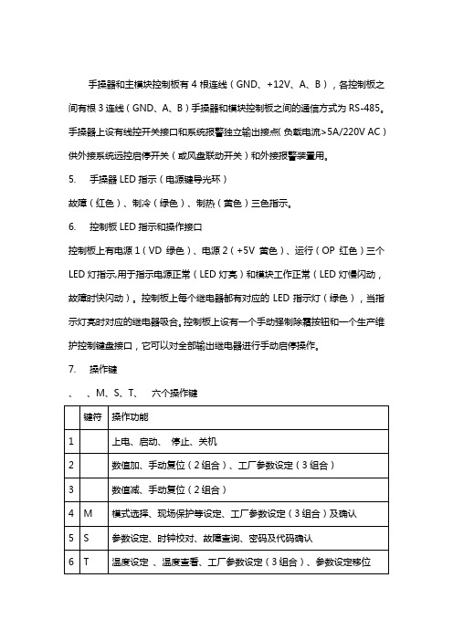
7. 操作键、、M、S、T、六个操作键8.操作说明8.1 开机长按(3s)电源键开机,LCD显示产品数列号(缺省值为00 00),系统进入待机状态,LCD常显示系统回水温度,水泵启动。
8.2 工作模式选择按M键进行‘制冷’→‘制热’→‘自动’循环选择,短按电源键确认,对应工作模式的指示符号闪动,延时3min后根据设定的温度条件开始启动相应设备,LCD 显示已被启动的设备指示符号。
8.3 温度设定(回水温度)设定工作模式后,按T键进入确定模式下的控制温度,LCD显示原设定温度值并闪动,用∧/∨键修改温度值,按T键退出。
8.4 查看温度长按T键LCD显示模块代号(如SYS A),短按T键进入温度查询状态,用∧/∨键查看1~8个温度;按T键退出或者延时约30s后自动退出(下同)。
8.5 故障保护查看长按S键进入故障查看,如有保护故障出现,LCD显示警钟、模块代码和各模块的故障保护代号:flow (水流)、1(1#压缩机高压)、2(1#压缩机低压)、3(1#压缩机过载)、4(1#冷凝风机过载)、5(2#压缩机高压)、6(2#压缩机低压)、7(2#压缩机过载)、8(2#冷凝风机过载);温度传感器故障时LCD显示模块代号、警钟和温度符号,故障传感器的温度显示为空,可参照8.4查看各路温度的状态。
三菱重工海尔集控系统操作流程

集控系统操作流程一、登入系统1)点击谷歌浏览器2)在地址栏中输入“192.168.1.10”;3) 用户名为“Admin”,密码默认为“123456”二、内机监控详解:1. 图中所标注的“1”建筑和区域所形成的层级树。
2. 图中所标注的“2”显示“当前页”的内机的个数和选中的数量。
3. 图中所标注的“3”批量设定选中内机的参数。
(点击后会弹出批量控制页面)4. 图中所标注的“4”是否选中“当前页的所有机组”。
5. 图中所标注的“5”选择的建筑或者区块名称。
6. 图中所标注的“6”机组显示的模块。
7. 图中所标注的“7”是否选中一个对应的机组。
8. 图中所标注的“8”当前建筑或者当前节点的页码控制。
9. 图中所标注的“9”内机的显示状态和是否有故障提示。
表示冷房模式 表示自动模式 表示送风模式 表示除湿模式表示暖房模式 表示通信异常 表示出现故障三、批量设定内机,需执行以下步骤:1.选择需要设定的机组,选择全选选中或者取消选中当前页面的所有机组。
2.选择“开关控制”。
3.选择“运转模式” 。
4.选择“风速设定”。
5.填写“温度设定”。
6.选择“摆叶位置”。
7.选择“控制模式”。
8.选择“滤网复位”。
9.选择“定期点检”。
10.选择“禁止线控”。
11.点击“确定”按钮执行,点击“取消”按钮取消。
✧若在批量设定页面中输入错误的信息,当点击确定按钮的时候,系统会有对应的错误提示。
✧当设定成功之后,并且页面会变成灰色,页面中出现的旋转的圆圈表示命令正在执行。
执行完毕后,页面右下角会弹出“设定成功”的提示框。
四、单台或批量设定内机,需执行以下步骤:1. 选中需要设定的内机。
(勾选内机名称前面的复选框,可单选或多选)2. 点击“批量设定选中内机参数”按钮。
3. 选择“开关控制”。
4. 选择“运转模式”。
5. 选择“风速设定”。
6. 填写“温度设定”。
7. 选择摆叶位置。
8. 选择“控制模式”。
9. 选择“滤网复位”。
螺杆冷水机组维修调试手册

安装调试和维护手册青岛海尔空调电子有限公司2004年6月目录机组简介第一章机组安装1.1货运及存放1.2机组安装前期准备1.3机组的吊运及定位1.4管道连接1.5 现场冷媒充注1.6电气连接第二章机组运转2. 1机组运转前的检查项目2.2机组运行2. 3机组运行控制2. 4运行管理和停机注意事项第三章机组维护保养和故障处理3.1概述3.2维护3.3水质管理3.4故障处理初次安装调试海尔水冷冷水螺杆机组之前,操作施工人员应当完全熟悉机组操作说明和其他必要的工作资料,并仔细阅读本手册内容。
了解相应的安装、调试、维护注意事项及相关要求,保证安装规范,使机组运行于最佳状态。
机组简介:水冷半封螺杆型冷水机组是一种以水为冷却介质的中央空调产品,和相同冷量的风冷机组相比,由于其冷凝器和蒸发器均采用特制高效传热管制作,因此结构紧凑,体积小,效率高;又由于没有冷凝风机,因而噪声低。
本公司在水冷半封螺杆型冷水机组制造方面有着成熟的技术,完善的工艺和先进的检测设备,再加上精选的国际一流配件,保证了机组的稳定、高效运行。
海尔水冷半封闭螺杆型冷水机组既能为宾馆、医院、药厂、影剧院、体育馆、娱乐中心、商业大厦、工矿企业等场所的中央空调系统提供冷水,也可为纺织、化工、食品、电子、科研等部门提供工艺冷冻水。
1.机组铭牌——位于机组控制箱的左侧。
2.系统部件——包括蒸发器,冷凝器,压缩机,节流装置,控制系统等。
3.型号命名法:LS B LGHX由于设备内部的相对压力、电器元件、以及安装位置等因素,操作时一定要注意安全,要先看清楚有关说明书,及各种标签上所列的安全注意事项。
第一章 机组安装 1.1货运及存放1.1.1发货 海尔水冷半封闭螺杆式冷水机组一般在工厂组装为一个整体,即由工厂加工装配、配管布线、氦检漏试验、充注制冷剂、进行性能测试、保温并经过全过程注意:本手册所介绍的知识并不意味读过本手册任何人可承担安装、调试、操作和维护中的任何一项工作。
螺杆冷水机组维修调试参考手册教材

安装调试与维护手册青岛海尔空调电子有限公司2004年6月目录机组简介第一章机组安装1.1货运及存放1.2机组安装前期准备1.3机组的吊运及定位1.4管道连接1.5 现场冷媒充注1.6电气连接第二章机组运转2. 1机组运转前的检查项目2.2机组运行2. 3机组运行控制2. 4运行管理和停机注意事项第三章机组维护保养与故障处理3.1概述3.2维护3.3水质管理3.4故障处理初次安装调试海尔水冷冷水螺杆机组之前,操作施工人员应当完全熟悉机组操作说明和其他必要的工作资料,并仔细阅读本手册内容。
了解相应的安装、调试、维护注意事项及相关要求,保证安装规范,使机组运行于最佳状态。
机组简介:水冷半封螺杆型冷水机组是一种以水为冷却介质的中央空调产品,与相同冷量的风冷机组相比,由于其冷凝器和蒸发器均采用特制高效传热管制作,因此结构紧凑,体积小,效率高;又由于没有冷凝风机,因而噪声低。
本公司在水冷半封螺杆型冷水机组制造方面有着成熟的技术,完善的工艺和先进的检测设备,再加上精选的国际一流配件,保证了机组的稳定、高效运行。
海尔水冷半封闭螺杆型冷水机组既能为宾馆、医院、药厂、影剧院、体育馆、娱乐中心、商业大厦、工矿企业等场所的中央空调系统提供冷水,也可为纺织、化工、食品、电子、科研等部门提供工艺冷冻水。
1. 机组铭牌——位于机组控制箱的左侧。
2. 系统部件——包括蒸发器,冷凝器,压缩机,节流装置,控制系统等。
3. 型号命名法:1.1货运及存放1.1.1发货海尔水冷半封闭螺杆式冷水机组一般在工厂组装为一个整体,即由工厂加工装配、配管布线、氦检漏试验、充注制冷剂、进行性能测试、保温并经过全过程的质量检验后完成合格产品的制造。
1.1.2交货机组由本公司负责运输到工程工地,当物流公司将机组运到用户现场时,销售人员协调当地经销商和用户负责卸货,对机组进行检查办理签收事项。
当场对照机组的铭牌、装箱清单上所列的随机附件、随机证件等项目进行检查。
三菱重工空调使用说明书
● Display brightness can be adjusted, follow procedure on !. Require Wireless LAN connecting adapter which available as accessory.
2 PREPARATION BEFORE USE
disconnect the power supply or turn off the breaker. • This appliance can be used by children aged from 8 years and above and persons
with reduced physical, sensory or mental capabilities or lack of experience and knowledge if they have been given supervision or instruction concerning use of the appliance in a safe way and understand the hazards involved. Children shall not play with the appliance. Cleaning and user maintenance shall not be made by children without supervision. • This appliance is not intended for use by persons (including children) with reduced physical, sensory or mental capabilities, or lack of experience and knowledge, unless they have been given supervision or instruction concerning use of the appliance by a person responsible for their safety. • Children should be supervised to ensure that they do not play with the appliance. • Do not use any refrigerant different from the one specified for complement or replacement. Otherwise, abnormally high pressure may be generated in the refrigeration cycle, which may result in a failure or explosion of the product or an injury to your body.
海尔冷水机组调试维护手册(风冷模块)

冷水机组调试维护手册(风冷模块)青岛海尔空调电子有限公司2003年10月目录机组介绍............................................ ........... . (3)电控箱示意图..................................................... .4机组调试工具准备............................................ .. .5调试前检查............................................ ........ . (5)…………………………………….. …….. …. . 5机组检查............................................ ........ . (6)水系统检查............................................ ........ . (7)电系统检查调试过程............................................ ........... .. (7)............................................ ........ . (7)水系统调试......................................... (8)收操器、信号线连线............................................ ........... (8)水泵调试............................................ (9)靶式流量开关调试正式开机调试............................................ . (10)............................................ ........... (10)准备工作…………………………………….. ……….. . ..11开机步骤…………………………………….. ……….. . ..12观察记录............................................ ....... (12)室内末端调试故障问题分析处理............................................ . (13)维护保养............................................ ........... . (14)机组简介:海尔风冷模块式冷(热)水机组是我公司为宾馆、医院、影剧院、体育馆、娱乐中心、商业大厦、写字楼、工矿企业等场所开发设计的中央空调产品,它可安装于屋顶或室外庭院,不需专用机房和冷却塔。
三菱重工空调说明书
操作說明書空調器2-19在操作空調器前,請細讀此操作說明,並保存此書以備日後參考。
安裝前,安裝人員應:閱讀安裝說明,並要求顧客保留此安裝説明以備將來參考。
取出包裝在室内機箱子的遙控器。
如果將本空調器轉讓給新的用戶或送往回收廠,請務必將本説明書一并交出。
Operating Instructions Air Conditioner20-37Before operating the unit, please read these operating instructions thoroughly and keep them for future reference.Before installation, the installer should:Read the Installation Instructions, then request the customer keep them for future reference.Remove the remote control packed with the indoor unit.If the equipment is transferred to a new user or delivered to a recycling plant, be sure also to hand over the manual.Model No.Indoor UnitOutdoor UnitRS-YU9ZK RS-YU12ZK RU-YU9ZK RU-YU12ZKOperating InstructionsAir ConditionerACXF55-338902簡易指南提供快速的製冷和最高的舒適感。
請在室內機遙控接收器的 8 米範圍内使用遙控器。
裝入電池3211拉出遙控器的背蓋。
2裝入 AAA 或 R03 電池。
3把蓋關上。
A 時間設定1按下 ,然後按下並設置時間。
海尔冷水机组调试维护手册 风冷模块

冷水机组调试维护手册(风冷模块)青岛海尔空调电子有限公司2003年10月目录机组介绍............................................ ........... . (3)电控箱示意图..................................................... .4机组调试工具准备............................................ .. .5调试前检查............................................ ........ . (5)…………………………………….. …….. …. . 5机组检查............................................ ........ . (6)水系统检查............................................ ........ . (7)电系统检查调试过程............................................ ........... .. (7)............................................ ........ . (7)水系统调试......................................... (8)收操器、信号线连线............................................ ........... (8)水泵调试............................................ (9)靶式流量开关调试正式开机调试............................................ . (10)............................................ ........... (10)准备工作…………………………………….. ……….. . ..11开机步骤…………………………………….. ……….. . ..12观察记录............................................ ....... (12)室内末端调试故障问题分析处理............................................ . (13)维护保养............................................ ........... . (14)机组简介:海尔风冷模块式冷(热)水机组是我公司为宾馆、医院、影剧院、体育馆、娱乐中心、商业大厦、写字楼、工矿企业等场所开发设计的中央空调产品,它可安装于屋顶或室外庭院,不需专用机房和冷却塔。
三菱重工海尔控制面板说明书

三菱重工海尔控制面板说明书
三菱重工海尔控制面板说明书是一份用于指导用户正确使用该
控制面板的重要文档。
本说明书旨在提供简明扼要的操作指南,帮助用户充分了解控制面板的功能和使用方法,以确保安全、高效地操作。
1.控制面板概述
本章节将介绍控制面板的外观和基本功能,包括各个按钮、指示灯的作用,以及控制面板上的显示屏和触摸功能等。
2.控制面板安装与连接
本章节将详细介绍如何正确安装控制面板,并连接到相应的设备。
提供了安装步骤、连接方法和注意事项等内容。
3.控制面板操作
本章节将逐一介绍控制面板上各个功能按钮的使用方法和操作
步骤。
涵盖了开关机、调节温度、设定定时器、选择模式等常用操作。
4.高级功能设置
本章节将介绍一些更高级的功能设置,如语言选择、音量调节、屏幕亮度调节等。
并提供了相应的操作指引和注意事项。
5.故障排除与维护
本章节将列举一些常见问题和解决方法,帮助用户在遇到故障时能够快速排除问题。
同时,提供了控制面板的维护方法和注意事项。
6.安全注意事项
本章节将重点强调用户在使用控制面板时需要注意的安全事项,包括使用环境要求、电源接线要求、防护措施等内容。
海尔空调安装指南说明书
Installation InstructionsNOTE: Read the entire instruction manual before starting the installation.Safety ConsiderationsImproper installation, adjustment, alteration, service, maintenance, or use can cause explosion, fire, electrical shock, or other conditions which may cause death, personal injury or property damage. Consult a qualified installer, service agency, or your distributor or branch for information or assistance. The qualified installer or agency must use factory-authorized kits or accessories when modifying this product.Refer to the individual instructions packaged with the kits or accessories when installing.Follow all safety codes. Wear safety glasses, protective clothing, and work gloves. Use quenching cloth for brazing operations. Have fire extinguisher available. Read these instructions thoroughly and follow all warning or cautions included in literature and attached to the unit.Consult local building codes and the current editions of the National Electrical Code (NEC) NFPA 70.In Canada, refer to the current editions of the Canadian Electrical Code CSA C22.1.Recognize safety information. When you see this symbol on the unit and in instructions or manuals, be alert to the potential for personal injury. Understand the signal words DANGER, WARNING, CAUTION,and NOTE. These words are used with the safety-alert symbol.DANGER identifies the most serious hazards which will result in severe personal injury or death. WARNING signifies hazards which could result in personal injury or death. CAUTION is used to identify unsafe practices which may result in minor personal injury or product and property damage. NOTE is used to highlight suggestions which will result in enhanced installation, reliability, or operation.CVPVA, CSPVACased Cooling Only Evaporator Coil Upflow / Downflow!PROPERTY DAMAGE HAZARD — FURNACE/COIL MATCHINGFailure to follow this warning could result in property damage, personal injury, or death.This coil must be matched to heating equipment that meets all CSA/ANSI Z21.47 or cooling equipment that meets UL 1995 or UL 60335-2-40. Refer to the furnace/blower installation instructions for any potential considerations when installing coils with composite drain pans.!PARTIAL UNIT REQUIREMENTSFailure to follow this warning could result in equipment damage.This family of evaporator coils are PARTIAL UNIT AIR CONDITIONER, complying with PARTIAL UNIT requirements of UL/CSA 60335-2-40 Standard, and must only be connected to other units that have been confirmed as complying to corresponding PARTIAL UNIT requirements of this UL/CSA 60335-2-40 Standard.!PERSONAL INJURY / PROPERTY DAMAGE HAZARDFailure to follow this warning could result in property damage, personal injury, or death.For continued performance, reliability, and safety, the only approved accessories and replacement parts are those specified by the equipment manufacturer. The use of non-manufacturer approved parts and accessories could invalidate the equipment limited warranty and result in fire risk, equipment malfunction, and failure. Please review manufacturer’s instructions and replacement part catalogs available from your equipment supplier.!ELECTRICAL SHOCK HAZARDFailure to follow this warning could result in personal injury or death.Before installing, modifying or servicing system, always turn off main power to system. There may be more than one disconnect switch. Lock out and tag switch with a suitable warning label.!UNIT DAMAGE HAZARDThe coil is not approved for Heat Pump application. Unit damage may occur!PERSONAL INJURY HAZARDFailure to follow this caution may result in personal injury.This coil contains Nitrogen precharge of 7 – 10 PSIG. Release this pressure through the center of the rubber plugs before removing plugs.!EXPLOSION HAZARDFailure to follow this warning could result in death, serious personal injury, and/or property damage.Never use air or gases containing oxygen for leak testing or operating refrigerant compressors.Pressurized mixtures of air or gases containing oxygen can cause an explosion.IMPORTANT: Nitrogen can leak out through the hole that the needle pierced in the plugs. This does not indicate a leaking coil nor warrant return of the coil.IMPORTANT: Dry fit all connections to systems (electrical, drains,refrigerant lines, flue & intake, etc.) first to verify no interferences before final connections are made.IntroductionUse this instruction manual to install indoor coils on upflow or downflow furnaces in cooling applications only. Do not use these coils in heat pump applications. Do not install in the horizontal position.These coils are enclosed in a painted casing, have factory-installed TXVs, and are used with Puron refrigerant R-410A systems.InstallationThese units can be installed in upflow or downflow configurations.Before installation, there are several performance requirements that must be considered because poor installation can negatively alter performance. This section will briefly discuss those factors.AirflowAirflow amount and distribution are vital to adequate system performance. Problems that can be experienced with incorrect airflow include:•low system performance •restricted TXV •frosted coil•poor humidity control •water blow-offWhen attaching the coil and building the plenum, pay special attention to the effect these details will have on airflow. After system start-up, check the cfm to insure that it is correct. (Generally, the cfm should be 350 to 450 cfm/ton during normal cooling operation.)TXVA thermal expansion valve is utilized in this coil design to optimize performance and comfort throughout the entire operating range of the system. Special attention needs to be taken to the TXV when installing the coil (Fig.1):•Do not overheat valve. Temperatures that exceed 212°F (100°C) can harm valve performance. Use a wet cloth or heat sink when brazing.•Place liquid filter dryer near indoor unit to reduce the risk of debris clogging the valve.•Make sure TXV bulb is securely fastened with a metal strap and wrapped in the indentation on vapor line tube.These specific coils have a factory-installed hard-shutoff TXV designed only for use with R-410A refrigerant. Use only with outdoor units designed for R-410A.NOTE: These TXVs are factory set at approximately 10° superheat measured at the suction service valve, and are not field adjustable.A210138Fig. 1 – TXV BulbCabinet SweatingIf this unit is installed in a garage, attic, or other unconditioned space,special attention needs to be given to the potential of cabinet sweating. A 6-in (152 mm) wide piece of insulation should be wrapped around the coil casing and supply duct connection point.Inspect EquipmentFile claim with shipper if equipment is damaged.Select Installation ProcedureNOTE: Furnace coils are not approved to be used in fan coil or “draw-through” type applications.To install cased coils in upflow applications, follow the instructions below (Upflow Coil Installation on p2).To install cased coils in downflow applications, follow the instructions below, (Downflow Coil Installation on p5).See Table 1 for coil connection options. Refer to instructions for placement of coil casing on furnace.NOTE: We recommend a 4" transition for peak performance, but it is not required unless stated.Installation of Evaporator CoilsUpflow Coil InstallationThe cased coil is designed to fit furnaces of the same width (Fig.2).1.Set coil in place on upflow furnace discharge air opening.!CUT HAZARDFailure to follow this caution may result in personal injury.Sheet metal parts may have sharp edges or burrs. Use care and wear appropriate protective clothing and gloves when handling parts.!UNIT OR PROPERTY DAMAGE HAZARDFailure to follow this caution may result in property damage.Make sure that Aluminum tubes do not come in direct contact or allow for condensate run off with a dissimilar metal. Dissimilar metals can cause galvanic corrosion and possible premature failure.CAUTION!ENVIRONMENTAL HAZARDFailure to follow this caution may result in environmental damage.Federal regulations require that you do not vent refrigerant to theatmosphere. Recover during system repair or final unit disposal.CAUTION!PROPERTY DAMAGE HAZARDFailure to follow this caution may result in property damage.Installing coils rotated 90° from the front of the furnace, in upflow or downflow applications, may cause water blow-off or coil freeze-up due to the concentration of air on one slab of the coil or lack of air to a slab of the coil. It is required that on this type of application, a field-supplied adapter be placed between the coil and furnace to allow air to distribute properly between all slabs of the coil.Vapor LineSensing Bulb IndentationSensing BulbWrap2.Ensure coil is level for proper condensate drainage. Do not tip coiltoward condensate drain. Coil casing does not need to be fastened or screwed to furnace.3.When installing wider coil on narrower furnace, it is recommendedto use a transition adapter (Fig.3).NOTE: On upflow installations where the indoor coil is placed in an unconditioned space, a 6" wide piece of insulation should be applied and wrapped around the outside of coil casing and supply duct contact point.Consult the furnace installation instructions for any special requirements when installing the coil to the furnace.A200227BFig. 2 – Typical Flush-Fit Coil Installation on Furnace(recommended)A200228BFig. 3 – Adapter(s) Installation When Coil is Larger than Furnace(recommended)Table 1 – Coil Connections / OrientationsModelNom. TonsLine Set Connection Tube Size, in.Flush Fit to Furnace Width,in. (mm)Fits Next Smaller FurnaceWidth 90° Rotation to Furnace (4" Min. Transition Required)180° Rotation toFurnace Suction LiquidEqual OverhangOffset LeftOffset Right CSPVA2414XMC 23/43/814-3/16 (360)ALLUpflow or DownflowCVPVA1814XMC 1.53/43/814-3/16 (360)CVPVA1917XMC 1.53/43/817-1/2 (445)X X X CVPVA2414XMC 23/43/814-3/16 (360)CVPVA2417XMC 23/43/817-1/2 (445)X X X CVPVA2517XMC 23/43/817-1/2 (445)X X X CVPVA3014XMC 2.53/43/814-3/16 (360)CVPVA3017XMC 2.53/43/817-1/2 (445)X X X CVPVA3117XMC 2.53/43/817-1/2 (445)X X X CVPVA3617XMC 33/43/817-1/2 (445)X X X CVPVA3621XMC 33/43/821 (533)X X X CVPVA3721XMC 33/43/821 (533)X X X CVPVA3817XMC 33/43/817-1/2 (445)X X X CVPVA4217XMC 3.57/83/817-1/2 (445)X X X CVPVA4221XMC 3.57/83/821 (533)X X X CVPVA4224XMC 3.57/83/824-1/2 (622)X X X CVPVA4821XMC 47/83/821 (533)X X X CVPVA4824XMC 47/83/824-1/2 (622)X X X CVPVA4924XMC 47/83/824-1/2 (622)X X X CVPVA6024XMC 57/83/824-1/2 (622)X X X CVPVA6124XMC57/83/824-1/2 (622)XXX(YDSRUDWRU6XSSO\5HWXUQ6XSSO\UpflowDownflowAirflow4” minimumAirflowA221112Fig. 4 – Smaller Furnace, Equal Overhang, Flush Mount(not recommended)A221113Fig. 5 – Smaller Furnace, Offset, Flush Mount Right or Left(not recommended)A221110Fig. 6 – 90° Rotation (shown in downflow)4" Transition Required (not recommended)A221111Fig. 7 – 180° Rotation (shown in upflow)(not recommended)AirflowAirflowFlush Mount Equal Overhang Flush MountAirflowAirflowDownflow Coil InstallationNOTE: In downflow installation with a 4-way multipoise furnace, break off perforated duct flanges on furnace. See furnace Installation Instructions.Refrigerant Line ConnectionsNOTE: Factory nitrogen charge may escape past rubber plugs during storage. This does not indicate a leaking coil nor warrant return of the coil.Size and install refrigerant lines according to information provided with outdoor unit. Coil connection tube sizes are shown in Table1. Route refrigerant lines to the coil in a manner that will not obstruct service access to the unit or removal of the filter.Do not use damaged, dirty, or contaminated tubing because it may plug refrigerant flow-control device. ALWAYS evacuate the coil and field-supplied tubing before opening outdoor unit service valves. Connect Refrigerant, Liquid, and Suction Lines For matched and mismatched systems, use line sizes recommended in outdoor unit Installation Instructions.The coil can be connected to outdoor units using field-supplied tubing of refrigerant grade. Always evacuate tubing and reclaim refrigerant when making connections or flaring tubing. Leak check connections before insulating entire suction line.See Table1 for coil connection tube size.1.Remove cabinet access door.2.Remove rubber plugs, suction plug then liquid plug, from coil stubsusing a pulling and twisting motion. Hold coil stubs steady to avoid bending or distorting.3.Remove fitting door with rubber grommets and slide fitting doorwith grommets onto the refrigerant lines (field line-set), away from braze joints.4.Fit refrigerant lines into coil stubs. Wrap a heat sinking materialsuch as a wet cloth behind braze joints.5.Wrap TXV and nearby tubing with a heat-sinking material such as awet cloth.e 1/2 psig Nitrogen purge in the suction and out the liquid line.7.Braze using a Sil-Fos or Phos-copper alloy. Do not use soft solder.8.After brazing, allow joints to cool. Carefully remove TXV bulbinsulation and verify that the TXV bulb is securely fastened with hose clamp. Tighten screw a half-turn past hand tight with TXV bulb placed in the indentation with full contact with the vapor line tube. Re-wrap TXV bulb with insulation.9.Leak check connections before insulating entire suction line.10.Slide fitting door with rubber grommets over joints. Position tubingat center of each grommet to ensure an air seal around the tube.Reinstall cabinet door.Refrigerant Metering DeviceThese Coils have a factory installed hard shut-off TXV designed only for use with R-410A refrigerant. Use only with outdoor units designed for R-410A.NOTE: These TXVs are factory set at approximately 10° superheat measured at the suction service valve, and are not field adjustable. These furnace coils use an R410A TXV. The TXVs are preset at the factory and do not need adjustment for reliable operation. Reference the outdoor unit instructions to properly charge the unit to the correct subcooling. Let the system stable out approximately 15 minutes after each charge adjustment.Condensate Drain Line Connection!PERSONAL INJURY HAZARDFailure to follow this warning could result in personal injury.Wear eye protection. Coil is factory charged with 7–10 psi nitrogen. The coil is under pressure and TXV screen is in place behind liquid line plug. DO NOT remove liquid line plug first, always remove the suctionline plug first to depressurize the coil.!UNIT OR PROPERTY DAMAGE HAZARDFailure to follow this caution may result in property damage.Take precautions to ensure Aluminum tubes do not come in direct contact or allow for condensate run off with a dissimilar metal. Dissimilar metals can cause galvanic corrosion and possible premature failure.!UNIT DAMAGE HAZARDFailure to follow this caution may result in damage.All aluminum tubing and coils must be adequately shielded from any copper braze splatter.!UNIT DAMAGE HAZARDFailure to follow this caution may result in product damage.To avoid valve damage to the refrigerant control device while brazing, valves must be wrapped with a heat-sinking material such as a wet cloth.!UNIT DAMAGE HAZARDFailure to follow this caution may result in product damage.DO NOT BURY MORE THAN 36 IN. OF REFRIGERANT TUBING IN GROUND. If any section of tubing is buried, there must be a 6-in. vertical rise to the valve connections on the outdoor unit. If more than the recommended length is buried, refrigerant may migrate to cooler buried section during extended periods of unit shutdown, causing refrigerant slugging and possible compressor damage at start-up.!PROPERTY DAMAGE HAZARDFailure to follow this caution may result in property damage.It is required that all drain connections that are not being used be fitted with ¾-inch male PVC plugs.When installing over a finished ceiling and/or living area, install a field-fabricated secondary condensate pan under the entire unit.The coil is designed to dispose of accumulated water through built-in condensate drain fittings. It is recommended that PVC fittings be used on the condensate pan. Do not over-tighten. Finger tighten plus 1-1/2 turns. Be sure to install PVC plugs in all unused condensate drain fittings (if not factory supplied).Four ¾-inch female threaded pipe connections are provided in each coil condensate pan.It is highly RECCOMMENDED and in some locals is it a code requirement to install a trap on the drain line(s). Please use the following guidelines to assure proper drainage:•Install a trap in condensate line of coil as close to the coil as possible.•Make trap at least 3 inches (76 mm) deep and no higher than the bottom of unit condensate drain opening (Fig.8).•Pitch condensate line 1 inch (25.4 mm) for every 10 ft. of length to an open drain or sump.•Make sure that the outlet of each trap is below its connection to condensate pan to prevent condensate from overflowing the drain pan.•Prime all traps, test for leaks, and insulate traps and lines if located above a living area.A200230CFig. 8 – Condensate TrapNOTE: If unit is located in or above a living space, where damage may result from condensate overflow, a field-supplied, external condensate pan should be installed underneath the entire unit, and a secondary condensate line (with appropriate trap) should be run from the unit into the pan. Any condensate in this external condensate pan should be drained to a noticeable place. As an alternative to using an external condensate pan, some localities may allow the running of a separate ¾-inch (19 mm) condensate line (with appropriate trap) per local code to a place where the condensate will be noticeable. The owner of the structure must be informed that when condensate flows from secondary drain or external condensate pan, the unit requires servicing or water damage will occur. To further protect against water damage, install a float switch to shut the unit off if the water in the secondary pan gets too high.A10216 Fig. 9 – Condensate Drain to Waste LineWaste Line ConnectionIf the condensate line is to be connected to a waste (sewer) line, an open trap must be installed ahead of the waste line to prevent escape of sewer gases (Fig.9).Humidifier ApplicationWhen installing a humidifier in a system which contains a V-coil or Slope coil, consideration must be given to location of coil slabs (Fig.10).1.The humidifier should be mounted to the supply plenum or returnduct whenever possible.2.Ensure that humidifier has adequate airflow.A200229BFig. 10 – Humidifier Application!PROPERTY DAMAGE HAZARD Failure to follow this warning could result in property damage.Provide trap with air gap in drain line when connecting to waste (sewer) line.Care and MaintenanceTo continue high performance and minimize possible equipment failure, it is essential that periodic maintenance be performed on this equipment. Consult your local dealer as to the proper frequency of maintenance, but it should be done at least annually.The ability to properly perform maintenance on this equipment requires certain mechanical skills and tools. If you do not possess these, contact your dealer for maintenance. The only consumer service recommended or required is filter replacement or cleaning on a monthly basis.!ENVIRONMENTAL HAZARDFailure to follow this caution may result in environmental damage. Remove and recycle all components or materials (i.e., oil, refrigerant,etc.) before unit final disposal.©2022 Carrier. All rights reserved.A Carrier Company.Edition Date: 6/22Catalog No: IM-CVPV A-02Replaces: IM-CVPV A-01。
海尔空调产品安装和使用说明书
SIMATIC 545/555/575 System ManualOrder Number: PPX:505-8201-3 Manual Assembly Number: 2804693-0003 Third EditionCopyright 2000 by Siemens Energy & Automation, Inc.All Rights Reserved — Printed in USAReproduction, transmission, or use of this document or contents is not permitted without express consent ofSiemens Energy & Automation, Inc. All rights, including rights created by patent grant or registration of a utility model or design, are reserved.Since Siemens Energy & Automation, Inc., does not possess full access to data concerning all of the uses and applications of customer’s products, we do not assume responsibility either for customer product design or for any infringements of patents or rights of others which may result from our assistance.MANUAL PUBLICATION HISTORYSIMATIC 545/555/575 System ManualOrder Manual Number: PPX:505–8201–3Refer to this history in all correspondence and/or discussion about this manual. Event Date DescriptionOriginal Issue03/96Original Issue (2804693–0001) Second Edition08/98Second Edition (2804693–0002) Third Edition06/00Third Edition (2804693–0003)LIST OF EFFECTIVE PAGESPages Description Pages DescriptionCover/Copyright Third EditionHistory/Effective Pages Third Editioniii — xxi Third Edition1-1 — 1-13Third Edition2-1 — 2-20Third Edition3-1 — 3-28Third Edition4-1 — 4-58Third Edition5-1 — 5-24Third Edition6-1 — 6-35Third Edition7-1 — 7-12Third Edition8-1 — 8-8Third Edition9-1 — 9-25Third EditionA-1 — A-5Third EditionB-1 — B-9Third EditionC-1 — C-23Third EditionD-1 — D-7Third EditionE-1 — E-16Third EditionF-1 — F-6Third EditionIndex-1 — Index-10Third EditionRegistration Third EditionContentsPrefaceChapter 1System Overview. . . . . . . . . . . . . . . . . . . . . . . . . . . . . . . . . . . . . . . . . . . . . . . . . . . . . . . . . . . . . . . . . . . . . . .1.1Overview1-2. . . . . . . . . . . . . . . . . . . . . . . . . . . . . . . . . . . . . . . . . . . . . . . . . . . . . . . . . . . . . . . . . . . .Introduction1-2. . . . . . . . . . . . . . . . . . . . . . . . . . . . . . . . . . . . . . . . . . . . . . . .Compatibility with Previous CPUs1-2. . . . . . . . . . . . . . . . . . . . . . . . . . . . . . . . . . . . . . . . . . . . . . . . . . .Features on New CPU Models1-3 . . . . . . . . . . . . . . . . . . . . . . . . . . . . . . . . . . . . . . . . . . . . . . . . . . . . . . . . . . . . . . . . . . .PROFIBUS-DP1-4. . . . . . . . . . . . . . . . . . . . . . . . . . . . . . . . . . . . . . . . . . . . . . . . . . . .PROFIBUS User Organizations1-4. . . . . . . . . . . . . . . . . . . . . . . . . . . . . . . . . . . . . . . . . . . . . . . . . . . . . . . . . . .Using Other Networks1-4. . . . . . . . . . . . . . . . . . . . . . . . . . . . . . . . . . . . . . . . . . . . . . . . . . . . . . . . . . . . . . . .1.2System Features1-6Product Specifications Overview1-6. . . . . . . . . . . . . . . . . . . . . . . . . . . . . . . . . . . . . . . . . . . . . . . .. . . . . . . . . . . . . . . . . . . . . . . . . . . . . . . . . . . . . . . . . . . . . . . . . . . . . . . . . . . . . . . .Shared Features1-8. . . . . . . . . . . . . . . . . . . . . . . . . . . . . . . . . . . . . . . . . . . . . . . . . . . . . . . . . .545/555-Only Features1-9. . . . . . . . . . . . . . . . . . . . . . . . . . . . . . . . . . . . . . . . . . . . . . . . . . . . . . . . . . . . . . .575-Only Features1-10. . . . . . . . . . . . . . . . . . . . . . . . . . . . . . . . . . . . . . . . . . . . . . . . . . . . . . . . . . . . . .1.3Programming Tools1-11. . . . . . . . . . . . . . . . . . . . . . . . . . . . . . . . . . . . . . . . . . . . . . . . . . . . . . . . . . . . . . . . . . . . . . .SoftShop1-11 . . . . . . . . . . . . . . . . . . . . . . . . . . . . . . . . . . . . . . . . . . . . . . . . . . . . . . . . . . . . . . . . . . . . . . . . . .TISOFT1-11 . . . . . . . . . . . . . . . . . . . . . . . . . . . . . . . . . . . . . . . . . . . . . . . . . . . . . . . . . . . . . . . . .COM PROFIBUS1-11. . . . . . . . . . . . . . . . . . . . . . . . . . . . . . . . . . . . . . . . . . . . . . . . . . .Communicating with the CPU1-11. . . . . . . . . . . . . . . . . . . . . . . . . . . . . . . . . . . . . . . . . . . . . . . . . . . . . . . . . . . . .1.4Hardware Overview1-12. . . . . . . . . . . . . . . . . . . . . . . . . . . . . . . . . . . . . . . . . . . . . . . . . . . . . . . . . . . . . . . . .Series 505 Bases1-12 . . . . . . . . . . . . . . . . . . . . . . . . . . . . . . . . . . . . . . . . . . . . . . . . . . . . . . . . . . . . . . . . . . . . . .VME Base1-12 . . . . . . . . . . . . . . . . . . . . . . . . . . . . . . . . . . . . . . . . . . . . . . . . . . . . . . . . . . . . . . . . . .Expansion I/O1-13. . . . . . . . . . . . . . . . . . . . . . . . . . . . . . . . . . . . . . . . . . . . . . . . . . . . . . . . . . . .I/O Channel Support1-13 Chapter 2Pre-installation Guidelines. . . . . . . . . . . . . . . . . . . . . . . . . . . . . . . . . . . . . . . . . . . . . . . . . . . . . . . .2.1Planning Your Installation2-2. . . . . . . . . . . . . . . . . . . . . . . . . . . . . . . . . . . . . . . . . . . . . . . . . .Defining Control Requirements2-2 Calculating Power Needs2-2. . . . . . . . . . . . . . . . . . . . . . . . . . . . . . . . . . . . . . . . . . . . . . . . . . . . . . .. . . . . . . . . . . . . . . . . . . . . . . . . . . . . . . . . . . . . . . . . . . . . . . . . . . . . . . . . . .2.2Safety Considerations2-3Operator Safety Switches2-4. . . . . . . . . . . . . . . . . . . . . . . . . . . . . . . . . . . . . . . . . . . . . . . . . . . . . . .. . . . . . . . . . . . . . . . . . . . . . . . . . . . . . . . . . . . . . . . . . . . . . . . . . . . . . . . .Emergency Stop Switch2-4. . . . . . . . . . . . . . . . . . . . . . . . . . . . . . . . . . . . . . . . . . . . . . . . . . . . . . . . . . . . .JOG or INCH Switch2-5 2.3575 Fault Relay Operation2-6. . . . . . . . . . . . . . . . . . . . . . . . . . . . . . . . . . . . . . . . . . . . . . . . . . . . . . .. . . . . . . . . . . . . . . . . . . . . . . . . . . . . . . . . . . . . . . . . . . . . . . . . . . . . . . . . . . . . . . . . . . . . . .Overview2-6. . . . . . . . . . . . . . . . . . . . . . . . . . . . . . . . . . . . . . . . . . . . . . . . . . . .Fault Relay Operation Details2-6 . . . . . . . . . . . . . . . . . . . . . . . . . . . . . . . . . . . . . . . . . . . . . . . . . . . . . . . . . . . . . . . . . . . . .Time Delay2-8. . . . . . . . . . . . . . . . . . . . . . . . . . . . . . . . . . . . . . . . . . . . . . . . . . . . .Fault Relay Usage Examples2-8Contents iii2.4Guidelines for Fuses/Circuit Breakers2-11. . . . . . . . . . . . . . . . . . . . . . . . . . . . . . . . . . . . . . . . . . . . .. . . . . . . . . . . . . . . . . . . . . . . . . . . . . . . . . . . . . . .Fusing the Controller and Remote I/O Base2-11 . . . . . . . . . . . . . . . . . . . . . . . . . . . . . . . . . . . . . . . . . . . . . . . . . . . . . . . . . . . . . . . . .2.5Electrical Noise2-12Definition and Source2-12. . . . . . . . . . . . . . . . . . . . . . . . . . . . . . . . . . . . . . . . . . . . . . . . . . . . . . . . . . .. . . . . . . . . . . . . . . . . . . . . . . . . . . . . . . . . . . . . . . . . . . . . . . . . . . . . .2.6Correcting Noise Problems2-13. . . . . . . . . . . . . . . . . . . . . . . . . . . . . . . . . . . . . . . . . . . . . . . . . . . . . . . . . . . . . . . . .Noise Snubbing2-13 . . . . . . . . . . . . . . . . . . . . . . . . . . . . . . . . . . . . . . . . . . . . . . . . . . . . . . . . . . . . . . . . . .Noise Isolation2-15. . . . . . . . . . . . . . . . . . . . . . . . . . . . . . . . . . . . . . . . . . . . . . . . . . . . . . . . . . . . . . .2.7Wiring Guidelines2-16. . . . . . . . . . . . . . . . . . . . . . . . . . . . . . . . . . . . . . . . . . . . . . . . . . . .2.8Grounding the Power System2-17Earth Ground2-17 . . . . . . . . . . . . . . . . . . . . . . . . . . . . . . . . . . . . . . . . . . . . . . . . . . . . . . . . . . . . . . . . . . .. . . . . . . . . . . . . . . . . . . . . . . . . . . . . . . . . . . . . . . . . . . . . . . . . . . . . . . . . . .Ground Connections2-18. . . . . . . . . . . . . . . . . . . . . . . . . . . . . . . . . . . . . . . .Grounding the 545/555 Controller Chassis2-19. . . . . . . . . . . . . . . . . . . . . . . . . . . . . . . . . . . . . . . . . . . . . . . . .Grounding the Cabinet or Rack2-19. . . . . . . . . . . . . . . . . . . . . . . . . . . . . . . . . . . . . . . . . . . . . . . . .Cable Management for the 5752-20. . . . . . . . . . . . . . . . . . . . . . . . . . . . . . . . . . . . . . . . . . . .Grounding the 575 Controller Chassis2-20 Grounding the Cabinet or Rack2-20. . . . . . . . . . . . . . . . . . . . . . . . . . . . . . . . . . . . . . . . . . . . . . . . . Chapter 3Installing 505 System Hardware. . . . . . . . . . . . . . . . . . . . . . . . . . . . . . . . . . . . . . . . . . . . . .3.1Overview of Installation Procedures3-2. . . . . . . . . . . . . . . . . . . . . . . . . . . . . . . . . . . . . .3.2Enclosure and Temperature Considerations3-3. . . . . . . . . . . . . . . . . . . . . . . . . . . . . . . . . . . . . . . . . . . . . . . . . . . . . . . . . . . . .Enclosure Selection3-3. . . . . . . . . . . . . . . . . . . . . . . . . . . . . . . . . . . . . . . . . . . . . . . . . . . . .Temperature Considerations3-3. . . . . . . . . . . . . . . . . . . . . . . . . . . . . . . . . . . . . . . . . . . . . . . . . . . . . . . . . . . . . . . .3.3Series 505 Bases3-4. . . . . . . . . . . . . . . . . . . . . . . . . . . . . . . . . . . . . . . . . . . . . . . . . . . . . . . . . . . . . . . . . . . . .Description3-4. . . . . . . . . . . . . . . . . . . . . . . . . . . . . . . . . . . . . . . . . . . . . . . .Grounding the Controller Chassis3-4. . . . . . . . . . . . . . . . . . . . . . . . . . . . . . . . . . . . . . . . . . . . . . . . .3.4Rack Mounting Series 505 Bases3-5. . . . . . . . . . . . . . . . . . . . . . . . . . . . . . . . . . . . . . . . . . . . . . . . .3.5Panel Mounting Series 505 Bases3-6. . . . . . . . . . . . . . . . . . . . . . . . . . . . . . . . . . . . . . . . . . . . . . . .3.6Installing Series 505 Power Supply3-8Power Budget for Series 505 Base3-8. . . . . . . . . . . . . . . . . . . . . . . . . . . . . . . . . . . . . . . . . . . . . . . .. . . . . . . . . . . . . . . . . . . . . . . . . . . . . . . . . . . . . . . . . . . . . . . .Power Supply Placement in Bases3-8. . . . . . . . . . . . . . . . . . . . . . . . . . . . . . . . . . . . . . .Installing and Removing the Power Supply3-8 Wiring the Power Supply3-10. . . . . . . . . . . . . . . . . . . . . . . . . . . . . . . . . . . . . . . . . . . . . . . . . . . . . . . . .. . . . . . . . . . . . . . . . . . . . . . . . . . . . . . . .3.7Installing the PROFIBUS-DP Annex Card (Optional)3-12. . . . . . . . . . . . . . . . . . . . . . . . . . . . . . . . . . . . . . . . . . . . . . . . . . . . . . .3.8Installing the 545/555 CPU3-14. . . . . . . . . . . . . . . . . . . . . . . . . . . . . . . . . . . . . . . . . . . . . . . . . . . . .CPU/RBC Location in a Base3-14. . . . . . . . . . . . . . . . . . . . . . . . . . . . . . . . . . . . . . . . . . . . . . . .Installing and Removing the CPU3-14iv Contents3.9Replacing and Handling the Battery3-16. . . . . . . . . . . . . . . . . . . . . . . . . . . . . . . . . . . . . . . . . . . . .. . . . . . . . . . . . . . . . . . . . . . . . . . . . . .Lithium Battery in the 545 and 555 –1105/–1106 CPUs3-16. . . . . . . . . . . . . . . . . . . . . . . . . . . . . . . . . . . . . . .Replacing the Battery in –1105/–1106 CPUs3-17 Lithium Battery in the 545 and 555 –1103/–1104 CPUs3-18. . . . . . . . . . . . . . . . . . . . . . . . . . . . . .. . . . . . . . . . . . . . . . . . . . . . . . . . . . . . . . . . . . . . . . . . . . . . . . . . . . . . . . . . . . . . . . . . . . . .Indicators3-18. . . . . . . . . . . . . . . . . . . . . . . . . . . . . . . . . . . . . . . . . . . . . . . . . . . .Using and Handling Batteries3-19. . . . . . . . . . . . . . . . . . . . . . . . . . . . . . . . . . . . . . . . . . . . . . . . . . . . . . . . . . .Transporting Batteries3-19. . . . . . . . . . . . . . . . . . . . . . . . . . . . . . . . . . . . . . . . . . . . . . . . . . . . . . . . . . . . . . . .Storing Batteries3-19. . . . . . . . . . . . . . . . . . . . . . . . . . . . . . . . . . . . . . . . . . . . . . . . . . . . . . . . . . . . .Discarding Batteries3-19. . . . . . . . . . . . . . . . . . . . . . . . . . . . . . . . . . . . . . .Replacing the Battery in –1103/–1104 CPUs3-20. . . . . . . . . . . . . . . . . . . . . . . . . . . . . . . . . . . . . . . . . . . . . . . . . . . . .3.10Setting the CPU Dipswitches3-22. . . . . . . . . . . . . . . . . . . . . . . . . . . . . . . . . . . . . . . . . . . . . . . . .Dipswitch Location and Settings3-22. . . . . . . . . . . . . . . . . . . . . . . . . . . . . . . . . . . . . . . . . . . . . . . . . . . . . . . .Enabling Battery Backup3-22. . . . . . . . . . . . . . . . . . . . . . . . . . . . . . . . . . . . . . . . . . .Enabling the Auto Recompile Function3-22. . . . . . . . . . . . . . . . . . . . . . . . . . . . . . . . . . . . . . . . . . . . . . . . . . . . . . . . . . . . . .Setting Baud Rates3-23 Communications Port 13-24. . . . . . . . . . . . . . . . . . . . . . . . . . . . . . . . . . . . . . . . . . . . . . . . . . . . . . . . .. . . . . . . . . . . . . . . . . . . . . . . . . . . . . . . . . . . . . . . . . . . . . . . . . . . . . . . . .Communications Port 23-24 . . . . . . . . . . . . . . . . . . . . . . . . . . . . . . . . . . . . . . . . . . . . . . . . . . . . . . . . . . . . . . . . . . . . . . . .I/O Ports3-25 3.11Installing Series 505 I/O Modules3-26. . . . . . . . . . . . . . . . . . . . . . . . . . . . . . . . . . . . . . . . . . . . . . . . .. . . . . . . . . . . . . . . . . . . . . . . . . . . . . . . . . . . . . . . . . . . . . . . . . . . . . . . . . . . . .Mixing I/O Modules3-26 Installing and Removing I/O Modules3-26. . . . . . . . . . . . . . . . . . . . . . . . . . . . . . . . . . . . . . . . . . . . Chapter 4Installing 575 System Hardware. . . . . . . . . . . . . . . . . . . . . . . . . . . . . . . . . . . . . . . . . . . . . .4.1Overview of Installation Procedures4-2. . . . . . . . . . . . . . . . . . . . . . . . . . . . . . . . . . . . . . .4.2Features of the PPX:575–2130 VMEbus Base4-3. . . . . . . . . . . . . . . . . . . . . . . . . . . . . . . . . . . . . . . . . . . . . . . . . . . . . . . . . . . . . . . . . . . . . . .Overview4-3. . . . . . . . . . . . . . . . . . . . . . . . . . . . . . . . . .4.3Features Required of a Third-Party VMEbus Base4-4. . . . . . . . . . . . . . . . . . . . . . . . . . . . . . . . . . . . . . . . . . . . . . . . . . . . .VMEbus Base Requirements4-4. . . . . . . . . . . . . . . . . . . . . . . . . . . . . . . .Determining the Condition of the 575 CPU Battery4-4. . . . . . . . . . . . . . . . . . . . . . . . . . . . . . . . . . . . . .4.4Enclosure and Temperature Considerations4-5. . . . . . . . . . . . . . . . . . . . . . . . . . . . . . . . . . . . . . . . . . . . . . . . . . . . . . . . . . . . .Enclosure Selection4-5. . . . . . . . . . . . . . . . . . . . . . . . . . . . . . . . . . . . . . . . . . . . . . . . . . . . .Temperature Considerations4-5. . . . . . . . . . . . . . . . . . . . . . . . . . . . . . . . . . . . . . . . . . . . . . . . . . . . . .4.5Installing the Fan Assembly4-6. . . . . . . . . . . . . . . . . . . . . . . . . . . . . . . . . . . . . . . . . . . . . . . . . . .Operating With Fan Assembly4-6. . . . . . . . . . . . . . . . . . . . . . . . . . . . . . . . . . . . . . . . . . . . . . . .Operating Without Fan Assembly4-6. . . . . . . . . . . . . . . . . . . . . . . . . . . . . . . . . . . . . . . . . . . . . . . . . . . . . . . . . . .Installation Sequence4-6 Selecting Voltage for Fan Operation4-7. . . . . . . . . . . . . . . . . . . . . . . . . . . . . . . . . . . . . . . . . . . . .. . . . . . . . . . . . . . . . . . . . . . . . . . . . . . . . . . . . . . . . . . . . . . . . . . .Wiring the AC Power Terminals4-7. . . . . . . . . . . . . . . . . . . . . . . . . . . . . . . . . . . . . . . . . . . . . . . . . . . . .Mounting the Fan Assembly4-8 Replacing Fuse on the Fan Assembly4-9. . . . . . . . . . . . . . . . . . . . . . . . . . . . . . . . . . . . . . . . . . . . .Contents v. . . . . . . . . . . . . . . . . . . . . . . . . . . . . . . . . . . . . . . . .4.6Installing the PPX:575–2130 VMEbus Base4-10. . . . . . . . . . . . . . . . . . . . . . . . . . . . . . . . . . . . . . . . . . . . . . . . . . . . . . . . . . . . .Mechanical Outline4-10. . . . . . . . . . . . . . . . . . . . . . . . . . . . . . . . . . . . . . . . . . . . . . . . . . . . . . . .Mounting Measurements4-10. . . . . . . . . . . . . . . . . . . . . . . . . . . . . . . . . . . . . . . . . . . . . .Mounting a Base in a 19-inch Rack4-11. . . . . . . . . . . . . . . . . . . . . . . . . . . . . . . . . . . . . . . . .NEMA Cabinet Mounting Measurements4-12. . . . . . . . . . . . . . . . . . . . . . . . . . . . . . . . . . . . . . . . . . . . . . . . . . . . . . . .Panel Mounting the Base4-12. . . . . . . . . . . . . . . . . . . . . . . . . . . . . . . . . . . . . . . . . . . . . . . .Grounding the Controller Chassis4-13. . . . . . . . . . . . . . . . . . . . . . . . . . . . . . . . . . . . . . . . . . . . . . . . . .4.7Installing the 575 Power Supply4-14Overview4-14 . . . . . . . . . . . . . . . . . . . . . . . . . . . . . . . . . . . . . . . . . . . . . . . . . . . . . . . . . . . . . . . . . . . . . . .. . . . . . . . . . . . . . . . . . . . . . . . . . . . . . . . . . . . .Selecting Input Voltage (PPX:575–6663 Only)4-16. . . . . . . . . . . . . . . . . . . . . . . . . . . . . . . . . . . . . . . . . . . . . . . . . .Installing the 575 Power Supply4-17. . . . . . . . . . . . . . . . . . . . . . . . . . . . . . . . . . . . . . . . . . . . . . . . . . . . . . . . . . . . . . .Wiring Guidelines4-17. . . . . . . . . . . . . . . . . . . . . . . . . . . . . . . . . . . . . . . . . . . . . . . . . . . . . . . . . . . . . . .Wiring Procedure4-18. . . . . . . . . . . . . . . . . . . . . . . . . . . . . . . . . . . . . . . . . . . . . . . . . . . . . . . . . . . .4.8Installing the Battery4-20Battery Backup for the 5754-20. . . . . . . . . . . . . . . . . . . . . . . . . . . . . . . . . . . . . . . . . . . . . . . . . . . . . .. . . . . . . . . . . . . . . . . . . . . . . . . . . . . . . . . . . . . . . . . . . . . . . . . . . . . . . . . . .Mounting the Battery4-20. . . . . . . . . . . . . . . . . . . . . . . . . . . . . . . . . . . . . . . . . . . . . . . . . . . . . . . . . . . .Disabling the Battery4-22 Battery Fuse4-22 . . . . . . . . . . . . . . . . . . . . . . . . . . . . . . . . . . . . . . . . . . . . . . . . . . . . . . . . . . . . . . . . . . . .. . . . . . . . . . . . . . . . . . . . . . . . . . . . . . .4.9Installing the Floating-Point Coprocessor (Optional)4-23. . . . . . . . . . . . . . . . . . . . . . . . . . . . . . . . . . . . . . . . . . . . . . . . . . . . . . . . . . . .4.10Configuring the CPU4-24Configuring the 575–2105/–2106 CPU4-24. . . . . . . . . . . . . . . . . . . . . . . . . . . . . . . . . . . . . . . . . . . .. . . . . . . . . . . . . . . . . . . . . . . . . . . . . . . . . . . . . . . . . . . . . . . . . . .Configuring the 575–2104 CPU4-24. . . . . . . . . . . . . . . . . . . . . . . . . . . . . . . . . . . . . . . . . . . . .Using the AUTO-CONFIGURED Mode4-26. . . . . . . . . . . . . . . . . . . . . . . . . . . . . . . . . . . . . . . . . . . . . .Using the USER-CONFIGURED Mode4-26. . . . . . . . . . . . . . . . . . . . . . . . . . . . . . . . . . . .Configuring the 575 Primary and Secondaries4-26. . . . . . . . . . . . . . . . . . . . . . . . . . . . . . . . . . . . . . . . . . .Enabling the Auto Recompile Function4-26. . . . . . . . . . . . . . . . . . . . . . . . . . . . . . . . . . . . . . . . . . . . . . . . . . . . . . . .Setting the Base Address4-27 . . . . . . . . . . . . . . . . . . . . . . . . . . . . . . . . . . . . . . . . . . . . . . . . . . . . . . . . . . . . . . . . .Issuing SYSRESET4-27. . . . . . . . . . . . . . . . . . . . . . . . . . . . . . . . . . .4.11Installing a Remote I/O Annex Card (Optional)4-28. . . . . . . . . . . . . . . . . . . . . . . . . . . . . . . . . . . . . . . . . . . . . .Configuring Annex Card Dipswitch4-28. . . . . . . . . . . . . . . . . . . . . . . . . . . . . . . . . . . . . . . . . . . . . . . .Annex Card Power Consumption4-28 Installing the Series 505 Remote I/O Annex Card4-29. . . . . . . . . . . . . . . . . . . . . . . . . . . . . . . . . .. . . . . . . . . . . . . . . . . . . . . . . . . . . . . . . . . . . . . . . . . . .Installing the PROFIBUS-DP Annex Card4-30. . . . . . . . . . . . . . . . . . . . . . . . . . . . . . . . . . . . . . . . . . . . . . . . . . . . . . . .4.12Installing VMEbus Boards4-32. . . . . . . . . . . . . . . . . . . . . . . . . . . . . . . . . . . . . . . . . . . . . . . . . . . . . . . . . . . . . . . . . . . .Introduction4-32. . . . . . . . . . . . . . . . . . . . . . . . . . . . . . . . . . . . . . . . . . . . . . . . . . . . . . . . . . . . .General Guidelines4-34. . . . . . . . . . . . . . . . . . .Guidelines for Installing a 575 System Controller or a Primary 5754-35 Guidelines for Installing or Adding a 575 Secondary to the System4-36. . . . . . . . . . . . . . . . .. . . . . . . . . . . . . . . . . . . . . . . . . . . . . . . . .Guidelines for Replacing a 575 System Controller4-37. . . . . . . . . . . . . . . . . . . . . . . . . . . . . . .Guidelines for Replacing a 575 Primary Not in Slot 14-38 Guidelines for Replacing a 575 Secondary4-39. . . . . . . . . . . . . . . . . . . . . . . . . . . . . . . . . . . . . . .. . . . . . . . . . . . . . . .Guidelines for Installing SIMATIC VMEbus I/O and Third-Party Boards4-40. . . . . . . . . . . . . . . . . . . . . . . . . . . . . . . . . . . . . . . . . . . . . . . .Setting the Daisy-Chain Switches4-41 . . . . . . . . . . . . . . . . . . . . . . . . . . . . . . . . . . . . . . . . . . . . . . . . . . . . . . . . . . . . . . . . .Slot Numbering4-41. . . . . . . . . . . . . . . . . . . . . . . . . . . . . . . . . . . . . . . . . . . .Installing and Removing I/O Modules4-42vi Contents4.13Wiring the Fault Relay4-44. . . . . . . . . . . . . . . . . . . . . . . . . . . . . . . . . . . . . . . . . . . . . . . . . . . . . . . . . . .. . . . . . . . . . . . . . . . . . . . . . . . . . . . . . . . . . . . . . . . . . . . . . . .4.14Establishing CPU Communication4-45. . . . . . . . . . . . . . . . . . . . . . . . . . . . . . . . . . . . . . . . . . . . . . . . . . . . . .Default Port Configurations4-45. . . . . . . . . . . . . . . . . . . . . . . . . . . . . . . . . . . . . . . . . . . . . . . . . . . . . . . . . . .Pinout for Serial Port 14-46. . . . . . . . . . . . . . . . . . . . . . . . . . . . . . . . . . . . . . . . . . . . . . . . .Pinouts for Serial Ports 2, 3, and 44-46 . . . . . . . . . . . . . . . . . . . . . . . . . . . . . . . . . . . . . . . . . . . . . . . . . . . . . . . . . . . . . . . . . . . . .Serial Port 14-47. . . . . . . . . . . . . . . . . . . . . . . . . . . . . . . . . . . . . . . . . . . . . . . . . . . . . . . . .Serial Port 2/ Printer Port4-48 . . . . . . . . . . . . . . . . . . . . . . . . . . . . . . . . . . . . . . . . . . . . . . . . . . . . . . . . . . . . . . . . . . . . .Serial Port 34-49 . . . . . . . . . . . . . . . . . . . . . . . . . . . . . . . . . . . . . . . . . . . . . . . . . . . . . . . . . . . . . . . . . . . . .Serial Port 44-49. . . . . . . . . . . . . . . . . . . . . . . . . . . . . . . . . . . . . . . . . . . . . . . .4.15Using Boards in the VMEbus Base4-50. . . . . . . . . . . . . . . . . . . . . . . . . . . . . . . . . . . . . . . . . . . . . . . . . . .Communicating with the CPU4-50 . . . . . . . . . . . . . . . . . . . . . . . . . . . . . . . . . . . . . . . . . . . . . . . . . . . . . . . . . . . . . . . . . . .Battery Status4-51. . . . . . . . . . . . . . . . . . . . . . . . . . . . . . . . . . . . . . . . . . . . . . . . . . .Using VMEbus Address Space4-51. . . . . . . . . . . . . . . . . . . . . . . . . . . . . . . . . . . . . . . . . . . . . . . . . . . . . . . . . . . . .Daisy-Chain Signals4-53. . . . . . . . . . . . . . . . . . . . . . . . . . . . . . . . . . . . . . . . .Assigning Addresses to Third-Party Slaves4-53. . . . . . . . . . . . . . . . . . . . . . . . . . . . . . . . . . . . . . . . . . . . . . . . . . . . . .VMEbus Access Limitations4-55. . . . . . . . . . . . . . . . . . . . . . . . . . . . . . . . . . . . . .4.16Installing Additional Backplane Connectors4-56. . . . . . . . . . . . . . . . . . . . . . . . . . . . . . . . . . . . . . . . . . . . . . . . . . . . . . . . . . . . . . . . . .J2 Backplanes4-56. . . . . . . . . . . . . . . . . . . . . . . . . . . . . . . . . . . . . . . . . . . . . . . . . .Optional J2 Mini Backplane Kit4-56. . . . . . . . . . . . . . . . . . . . . . . . . . . . . . . . . . . . . . . . . . . . . . . . .Installing Optional J2 Backplane4-57. . . . . . . . . . . . . . . . . . . . . . . . . . . . . . . . . . . . . . . . . . . . .Installing Optional J2 DIN Connector4-58 Chapter 5Installing Remote Base Controllers—RBCs. . . . . . . . . . . . . . . . . . . . . . . . . . . . . . . . . . . . . . . . . . . . . . . . . . . . . . . . . . . . . . . . . . . . . . .5.1Overview5-2. . . . . . . . . . . . . . . . . . . . . . . . . . . . . . . . . . . . . . . . . . . . . . . . . . . . . . . . . . . . . . . . . . . . .5.2Installation5-3. . . . . . . . . . . . . . . . . . . . . . . . . . . . . . . . . . . . . . . . . . . . . . . . . .Models Used in Series 505 Base5-3. . . . . . . . . . . . . . . . . . . . . . . . . . . . . . . . . . . . . . . . . . . . . . . . . . . . . . . . .RBC Placement in Base5-3. . . . . . . . . . . . . . . . . . . . . . . . . . . . . . . . . . . . . . . . . . . . . . . .Installing and Removing the RBC5-4. . . . . . . . . . . . . . . . . . . . . . . . . . . . . . . . . . . . . . . . . . . . . . . . . . . . . . . . . . .5.3Communication Ports5-5. . . . . . . . . . . . . . . . . . . . . . . . . . . . . . . . . . . . . . . . . . . . . . . . . . . . . . . . . . . . . . . . . . . . .RS-232 Port5-5 . . . . . . . . . . . . . . . . . . . . . . . . . . . . . . . . . . . . . . . . . . . . . . . . . . . . . . . . . . . . . . . . . . . . . . . .I/O Port5-5. . . . . . . . . . . . . . . . . . . . . . . . . . . . . . . . . .5.4PPX:505–6851–A/B and PPX:505–6850–A/B RBCs5-6. . . . . . . . . . . . . . . . . . . . . . . . . . . . . . . . . . . . . . . . . . . . . . . . . . . . . . . . . . . . . . . . . . . .User Options5-6. . . . . . . . . . . . . . . . . . . . . . . . . . . . . . . . . . . . . . . . . . . . . . . . . . . . . . . . . .Output State Selection5-6. . . . . . . . . . . . . . . . . . . . . . . . . . . . . . . . . . . . . . . . . . . . . . . . . . . . . . . . . . . . . .Dipswitch Options5-8 Series 505 Base Numbers5-9. . . . . . . . . . . . . . . . . . . . . . . . . . . . . . . . . . . . . . . . . . . . . . . . . . . . . . . .. . . . . . . . . . . . . . . . . . . . . . . . . . . . . . . . . . . . . . . . . . . . . . . .Changing the RBC Base Number5-9. . . . . . . . . . . . . . . . . . . . . . . . . . . . . . . . . . . . . . . . . . . . . . . . . . . . . . . . . . . . . . .Resetting the RBC5-11 Status Display5-12 . . . . . . . . . . . . . . . . . . . . . . . . . . . . . . . . . . . . . . . . . . . . . . . . . . . . . . . . . . . . . . . . . . .Contents vii。
海尔空调用户手册说明书
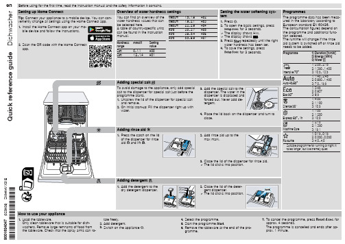
1) 0:15 - 0:15 2) 0,050 - 0,050 3) 4,0 - 4,0
1 Suitable programme for running at night: it takes longer, but is extremely quiet.
1
3. Close the lid of the dispenser for rinse aid. a The lid clicks into position.
3. Press
repeatedly until the right
water hardness has been set.
4. To save the settings, press
for 3 seconds.
3. Add the special salt to the dispenser. The water in the dispenser is displaced and forced out. Never add detergent.
The flow rate must be at least 10 l/min when the water supply is open.
The filters in the water connection of the supply or AquaStop hose are blocked. 1. Switch off the appliance. 2. Pull out the mains plug. 3. Turn off the water tap. 4. Unscrew the water connection. 5. Remove the filter from the sup-
三菱重工空调说明书
Thank you for choosing our product.Please read this Owner’s Manual carefully before operation and retain it for future reference.Owner's ManualOriginal InstructionsWireless Controller YAP1F7ACCMI-26HRDC1A ACCMI-36HRDC1A ACCMI-53HRDC1A ACMI-70HRDC1A1.1 Buttons on remote controller 1.2 Introduction for icons on display screen1.Operation and introductionof remote controllerDC Inverter Free match Series Cassette Type Unit31.3 Introduction for buttons on remote controllerPress this button to turn on the unit. Press this button again to turn off the unit.ion mode.AUTO COOL DRYFANHEATadjust fan blowing angle.Under COOL or HEAT mode, press this button toWhen selecting heating mode, the air condition-er operates under heat mode. Press "" or " " button to adjust set temperature. Press "FAN" button to adjust fan speed. Press " " / " " button to adjust fan blowing angle. (Cooling only unit won't receive heating mode signal. If setting heat mode with remote controller, press ON/OFF button can’t start up the unit).When selecting auto mode, air conditioner will operate automatically according to ex-factory setting. Press "FAN" button can adjust fan speed. Press " " / " " button can adjust fan blowing angle.After selecting cool mode, air conditioner will operate under cool mode. Press "" or " " button to adjust set temperature. Press "FAN" button to adjust fan speed. Press " " / " " button to adjust fan blowing angle.When selecting dry mode, the air conditioner operates at low speed under dry mode. Under dry mode, fan speed can’t be adjusted. Press " " / " " button to adjust fan blowing angle.When selecting fan mode, the air conditioner will only blow fan, no cooling and no heating. All indicators are OFF. Press "FAN" button to adjust fan speed. Press " " / " " button to,, to , then back to Auto.ƔƔƔƔThis button is used for setting Fan Speed in thesequence that goes from AUTO,, ,, 4setting.It '" "mode.ON/OFFƔƔƔƔƔƔPress this button can select left & right swing angle.Fan blow angle can be selected circularly as below:Press this button can select up & down swing angle. Fan blow angle can be selected circularly as below:Ɣ NOTENOTEƔWhen selecting " ", air conditioner is blowingfan automatically. Horizontal louver will automat-Hold " "button above 2s to set your required swing angle. When reaching your required angle, release the button. immediately.stated above.no display position)(stops at current“ 、 、fan automatically.stated above.Ɣ Ɣno display(horizontal louvers stops at current position)When selecting " ", air conditioner is、 、 ically swing up & down at maximum angle.When selecting 、 " "、 、 、, air condition-er is blowing fan at ¿xed position. Horizontal ORXYHU ZLOO VWRS DW WKH ¿[HG SRVLWLRQPress "" or " " button once increase or d e cr-ease set temperature 1℃ (°F). Holding "" or" " button, 2s later, set temperature on remote controller will change quickly. On releasing button after setting is finished, temperature indicator on indoor unit will change accordingly.When setting T-ON, T-OFF or CLOCK, press "" or " " button to adjust time. (Refer to CLOCK, T-ON, T-OFF buttons)blowing fan at ¿xed angle. Horizontal louver will VHQG DLU DW WKH ¿[HG DQJOH"T-ON" button can set the time for timer on. After button to cancel it.pressing this button, " " icon disappears and the word "ON" on remote controller blinks. Press "" or " " button to adjust T-ON setting. After each pressing "" or " " button, T-ON setting will increase or decrease 1min. Hold "" or " "button, 2s later, the time will change quickly u ntil reaching your required time. Press "T-ON " to confirm it. The word "ON" will stop blinking. "" icon resumes displaying. Cancel T-ON: Under thecondition that T-ON is started up, press "T-O N"button to cancel it. T-OFF button"T-OFF" button can set the time for timer off. Af-ter pressing this button, " " icon disappears and the word "OFF" on remote controller blinks. Press "" or " " button to adjust T-OFF setting. 5turn to quick COOL or quick HEAT mode. " " icon is displayed on remote controller. Press this button again to exit turbo function and " " icon will disappear. If start this function, the unit will run at super-high fan speed to cool or heat quickly so that the ambient temperature approaches the preset temperature as soon as possible.After each pressing "" or " " button, T-OFF setting will increase or decrease 1min. Hold "" or " " button, 2s later, the time will change qui-ckly until reaching your required time. Press "T-OFF" word "OFF" will stop blinking. " " icon resumes displaying. Cancel T-OFF. Under the condition that T-OFF is started up, press "T-OFF"ƔƔNOTEƔPress this button, can select Sleep 1 ( 1),Sleep 2 ( 2), Sleep 3 ( 3) and cancel theƔSleep, circulate between these, after electrified, Sleep Cancel is defaulted.Sleep 1 is Sleep mode 1, in Cool modes; sleep ' 6status after run for one hour, the main unit setting temperature will increase 1 , two hours, setting temperature increased 2℃, then the unit will run at this setting temperature; In Heat mode: sleep " button within 5s to set clock time. Each pressing of "" or "" button, clock time will increas e or decrease 1 min. If hold "" or "" button , 2s later, time will change quickly. Release this button when reaching your required time. Press "CLOCK" button to confirm the time. " " icon stops blink-ing.status after run for one hour, the setting tempera- ture will decrease 1 , two hours, setting tempera-ture will decrease 2 , then the unit will run at this setting temperature.ƔSleep 2 is sleep mode 2, that is air conditioner will run according to the presetting a group of sleep temperature curve.ƔSleep 3-the sleep curve setting under Sleep mode by DIY;(1) Under Sleep 3 mode, press “Turbo” button for a long time, remote controller enters into user indi-viduation sleep setting status, at this time, the time of remote controller will display “1hour”, the setting temperature “88” will display the corresponding temperature of last setting sleep curve and blink (The first entering will display according to the initial curve setting value of original factory);(2) Adjust “△” and “▽” button, could change the corresponding setting temperature, after adjusted, press “Turbo” button for confirmation;(3) At this time, 1hour will be automatically increased at the timer position on the remote con-trol, (that are "2hours" or "3hours" or "8hours"), the place of setting temperature "88" will display the corresponding temperature of last setting sleep curve and blink;(4) Repeat the above step (2)~(3) operation, until 8 hours temperature setting finished, sleep,curve setting finished, at this time, the remote controller will resume the original timer display; temperature display will resume to original setting temperature.ƔSleep3- the sleep curve setting under Sleep mode by DIY could be inquired:The user could accord to sleep curve setting method to inquire the presetting sleep curve, enter into user individuation sleep setting status, but do not change the temperature, press "Turbo " button directly for confirmation. Note: In the above preset-ting or enquiry procedure, if continuously within 10s, there is no button pressed, the sleep curve setting within 10s, there is no button pressed, the sleep curve setting status will be automatically quit and resume to display the original displaying. In the presetting or enquiry procedure, press "ON/OFF" button, "Mode" button, "Sleep" button, the sleep curve setting or enquiry status will quit similarly.function is set, the remote controller will send the detected ambient temperature to the controller a nd the unit will automatically adjust the indoor te-mperature according to the detected temperatu re. button again to cancel I FEEL function this function is set. Do not put the remote contro ller near the object of high temperature or low temper-ature in order to avoid detecting inaccurate ambie-nt temperature.When I FEEL function is turned on, the remote controller should be put within the a reawhere indoor unit can receive the signal sent bythe remote controller.Ɣ8ȭ heating functionƔƔƔNOTENOTEƔƔƔPress this button to turn off display light on indoor unit. " " icon on remote controller disappears. Press this button again to turn on display light. " " icon is displayed.7Under heat mode, press "TEMP" and "CLOCK" buttons simultaneously to start up or turn off 8ȭ ȭ" will be shown on remote controller, and the air conditioner keep the heating status at 8ȭ. Press "TEMP" and "CLOCK" buttons simulta-neously again to exit 8ȭ heating function.Press this button, you can see indoor set tempera-ture, indoor ambient temperature on indoor unit' s display. The setting on remote controller is select-ed circularly as below:Energy-saving function1.4 Function introduction for combination buttons''t''t oper-ƔNOTENOTEƔ Under 8ȭ' Under 8ȭ't be ' ȭ't operate at the same time. If 8ȭ heating function has been set ȭ heat mode, start up the 8ȭ heating function will cancel sleep function.Under ȯwill display 46ȯ heating.Press " WiFi " b utton to turn on WiFi function, "WiFi " icon will be displayed on the remote controller;Hold " WiFi " button for 5s to turn off WiFi function and " WiFi " icon will disappear.Under off status, press "MODE" and " WiFi " buttons simultaneously for 1s, WiF i module will restorefactory settings.Press this button to turn on or turn off the health and scavenging functions in operation status.Press this button for the first time to start scaveng-ing function; LCD displays " ". Press the button for the second time to start health and scaveng-ing functions; LCD displays " " and " ". Press this button for the third time to quit health and scavenging functions simultaneously. Press the button for the fourth time to start health function; LCD display " ". Press this button again to repeat the operation above.Under cooling mode, press "TEMP" and "CLOCK" buttons simultaneously to start up or turn off ener-gy-saving function. When energy-saving function is started up, "SE" will be shown on remote con-troller, and air conditioner will adjust the set tem-perature automatically according to ex-factory setting to reach to the best energy-saving effect. Press "TEMP" and "CLOCK" buttons simultane-ously again to exit energy-saving function.81. 2. 3. 4. Fig.1Reinstall the cover (as shown in Fig 2④).1.5 Replacement of batteries in remote controllerFig.2Lift the cover along the direction of arrow (as shown in Fig 1①).Child lock functionTemperature display switchover functionTake out the original batteries (as shown inFig 1②).Place two 7# (AAA 1.5V) dry batteries, and makesure the position of “ + ” polar and “ - ” polar is correct (as shown in Fig 2③).Under OFF status, press "" and "MODE" buttons simultaneously to switch temperature display between ȭ and ȯ.Press "" and "" simultaneously to turn on or turn off child lock function. When child lock func-tion is on, " " icon is displayed on remote control-ler. If you operate the remote controller, the " " icon will blink three times without sending signal to the unit.during operation.When you don ' 's66129937831。
海尔空调维护指南说明书
This filter should be replaced every 30,000miles (48,000km)under normal conditions.It should be replaced every 15,000miles (24,000km)if you drive primarily in urban areas that have high concentrations of soot in the air from industry and diesel-powered vehicles.Replace it more often if air flow from theheating and cooling system becomes less than usual.The dust and pollen filter removes pollen and dust that is brought in from the outside through the heating and cooling system.Remove the dust and pollen filter cover by pushing up on the lock tab,then pivoting up the cover.2.U.S.:All modelsCanada :Premium and Type-SOptional on RSXDust and Pollen Filter232Remove the first filter by pulling it straight out of the air conditioning unit.Remove the second filter by sliding it to the left,then pulling it out.Install the new filters.Reinstall the cover.Pivot the glove box up into position.Reinstall the hooks into the side panel of the glove box. Close the glove box.If you are not sure how to replace the dust and pollen filters,have them replaced by your Acura dealer.3.4.5.Dust and Pollen Filter233An auto-tensioner adjusts the tension of the drive belt.The indicator on the auto-tensioner should be in the proper range.It should be checked according to the time and distance recommendations in the maintenance schedule.If the indicator is not within the proper range,have the drive belt replaced by your Acura dealer as soon as possible.Drive BeltsDrive Belt234To safely operate your car,your tires must be the proper type and size,in good condition with adequate tread, and correctly inflated.The following pages give more detailed information on how and when to check air pressure,how to inspect your tires for damage and wear,and what to do when your tires need to be replaced.Check the pressure in the tires when they are cold.This means the car has been parked for at least three hours.If you have to drive the car before checking the tire pressure, the tires can still be considered‘‘cold’’if you drive less than1mile (1.6km).If you check the pressure when the tires are hot[the car has been driven several miles(kilometers)],you will see readings4to6psi(30to40kPa, 0.3to0.4kgf/cm)higher than the cold reading.This is normal.Do not let air out to match the specified cold pressure.The tire will be underinflated.You should get your own tire pressure gauge and use it whenever you check your tire pressures.This will make it easier for you to tell if a pressure loss is due to a tire problem and not due to a variation between gauges.CONTINUEDTires235Every time you check inflation,you should also examine the tires for damage,foreign objects,and wear.You should look for:Bumps or bulges in the tread or side of the tire.Replace the tire if you find either of these conditions.Cuts,splits,or cracks in the side of the tire.Replace the tire if you can see fabric or cord.Excessive tread wear.The following chart shows therecommended cold tire pressures for most normal driving conditions and speeds.Tire pressures for high speed driving are the same as for normal driving.InspectionRecommended Tire Pressures for Normal DrivingTires236In addition to proper inflation,correct wheel alignment helps to decrease tire wear.If you find a tire is worn unevenly,have your dealer check the wheel alignment.The tires were properly balanced by the factory.They may need to be rebalanced at some time before they are worn out.Have your dealer check the tires if you feel a consis-tent vibration while driving.A tire should always be rebalanced if it is removed from the wheel for repair.Your car’s tires have wear indicators molded into the tread.When the tread wears down to that point,you will see a 1/2inch (12.7mm)wide band running across the tread.This shows there is less than 1/16inch (1.6mm)of tread left on the tire.A tire that is this worn gives very little traction on wet roads.You should replace the tire if you can see the tread wear indicator in three or more places around the tire.Make sure the installer balances the wheels when you have new tires installed.This increases riding comfort and tire life.Your car’soriginal tires were dynamic or ‘‘spin’’balanced at the factory.For best results,have the installer perform a dynamic balance.(Only on cars equipped with aluminum wheels)MaintenanceTires237Improper wheel weights can damage your car’s aluminum e only genuine Acura wheel weights f orbalancing.When shopping for replacementtires,you may find that some tiresare‘‘directional.’’This means theyare designed to rotate only in onedirection.If you use directional tires,they should be rotated only front-to-back.To help increase tire life anddistribute wear more evenly,youshould have the tires rotated every10,000miles(16,000km).Move thetires to the positions shown in thechart each time they are rotated.Tire RotationTires238If you ever need to replace a wheel,make sure the wheel’s specifications match those of the original wheel that came on your car.Replacement wheels are available at your Acura dealer.The ABS works by comparing the speed of the wheels.When replacing tires,use the same size originally supplied with the car.Tire size and construction can affect wheel speed and may cause the system to work inconsistently.The tires that came with your car were selected to match the perform-ance capabilities of the car while providing the best combination of handling,ride comfort,and long life.You should replace them with radial tires of the same size,load range,speed rating,and maximum cold tire pressure rating (as shown on the tire’s sidewall).Mixing radial and bias-ply tires on your car can reduce its braking ability,traction,and steering accuracy.CONTINUEDReplacing Tires and Wheels Tires239Wheels:See page for information about DOT Tire Quality Grading.Tires that are marked ‘‘M S’’or ‘‘All Season’’on the sidewall have an all-weather tread design.They should be suitable for most winter driving conditions.Tires without these markings are designed for optimum traction in dry conditions.They may not provide adequate performance in winter driving.For the best performance in snowy or icy conditions,you should install snow tires or tire chains.They may be required by local laws under certain conditions.Tires:292(Canada :RSX)(U.S.:All modelsCanada :Premium and Type-S models)(Canada :RSX)(U.S.:All modelsCanada :Premium and Type-S models)Winter DrivingWheels and Tires Tires24015x 6JJ16x 61/2JJ P205/55R1689VP195/65R1589HMount snow chains on your car when warranted by driving condi-tions or required by local laws.Make sure the chains are the correct size for your tires.Install them only on the front tires.Use only SAE class ‘‘S’’chains.Only certain brands of chains will fit your Acura without coming in contact with the body or causing mechanical damage.Before buying any types of chains,you should consult with your Acura dealer about the designs and brands that will work on your Acura.Also,make sure you purchase the correct size for your tires.If you mount snow tires on your Acura,make sure they are radial tires of the same size and load range as the original tires.Mount snow tires on all four wheels to balance your car’s handling in all weather conditions.Keep in mind the traction provided by snow tires on dry roads may not be as high as your car’s original equipment tires.You should drive cautiously even when the roads are clear.Check with the tire dealer for maximum speed recommen-dations.When installing chains,follow the manufacturer’s instructions and mount them as tightly as you can.Drive slowly with chains installed.If you hear them contacting the body or chassis,stop and investigate.Make sure the chains are installed tightly,and that they are not contacting the brake lines orsuspension.Remove the chains as soon as you start driving on cleared roads.Snow Tires Tire ChainsTires241Chains of the wrong size or that are improperly installed can damage your car’s brake lines,suspension,body,and wheels.Stop driving if you hear the chains hitting any part of thecar.。
海尔空调产品维修指南说明书
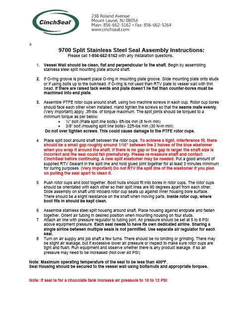
9700 Split Stainless Steel Seal Assembly Instructions:Please call 1-856-662-5162 with any installation questions.1. Vessel Wall should be clean, flat and perpendicular to the shaft. Begin by assemblingstainless steel split mounting plate around shaft.2. If O-ring groove is present place O-ring in mounting plate groove. Slide mounting plate onto studsor if using bolts up to the bulkhead. If O-ring is not used than RTV plate to vessel wall with thinbead. If there are raised tack welds and plate doesn’t lie flat than counter-bores must bemachined into end plate.3. Assemble PTFE rotor cups around shaft, using two machine screws in each cup. Rotor cup boresshould face each other when installed. Hand tighten the screws so that the seams mate evenly.(Very important) apply .3ft-lbs. of torque maximum. The split joints should be torqued to aminimum torque as per below:∙¼” bolt (Plate split line bolts)- 6ft-lbs min (8 N-m min)∙3/8” bolt (Housing split line bolts)- 22ft-lbs min (30 N-m min)Do not over tighten screws. This could cause damage to the PTFE rotor cups.4 Place split boot around shaft between the rotor cups. To achieve a tight, interference fit, thereshould be a small gap roughly around 1/16” between the 2 halves of the blue elastomerwhen you wrap it around the shaft. If there is no gap or the gap is larger the shaft size isincorrect and the seal could fail prematurely. Please re-measure shaft and contactCinchSeal before continuing. A new split elastomer may be needed. Put a good amount of supplied RTV Sealant in the split line and hold glued joint together for at least 3 minutes minimum for curing purposes. (Very Important) Do not RTV the split line of the elastomer if you planon pulling the seal apart to clean it.5 Push rotor cups and boot together. Boot hubs should fit into bores in rotor cups. The rotor cupsshould be orientated with each other so their split lines are 90 degrees apart from each other.Slide assembly on shaft until inboard rotor cup seats up against inner housing bore surface.There should be a slight resistance on the shaft when moving parts. Inside rotor cup, whereboot fits in should be kept clean.6 Assemble stainless steel split housing around shaft. Place housing against endplate and fastentogether. Orient air tubing in desired position when mounting housing on four studs.7 Attach air line with pressure regulator to tubing port. Air pressure should be set at 5 to 8 PSIabove equipment pressure. Each seal needs to have its own dedicated airline. Sharing asingle airline between multiple seals is not permitted. Use separate air regulator for each seal.8 Turn on air supply and job shaft a few turns. There should be no binding or grinding. There maybe slight air leakage, but if excessive lower air pressure or inspect to make sure rotor cups aretight and flush. Run equipment and observe whether there is any product leakage. If so airpressure may need to be increased (Not over 40 PSI)Note: Maximum operating temperature of the seal to be less than 400ºF.Seal Housing should be secured to the vessel wall using bolts/nuts and appropriate torques. Note: If seal is for a chocolate tank increase air pressure to 10 to 12 PSI。
海尔空调安装和使用说明书

INSTALLATION AND OPERATING INSTRUCTIONSPUMPP/N 88751-509/05Model:DTSE and LTSERAPW WYOTT Foodservice Equipment CompanyP .O.Box 1829Cheyenne,WY 82003+1(307)634-5801Phone +1(800)752-0863Toll Free +1(307)637-8071Fax INSTALLATIONOPERATIONCLEANING1.Clean the pump thoroughly before using it for the first time,according to the cleaning instructions below.To install the lid,hold the pump upright,unscrew the two retaining nuts,and remove the piston rod and spout from the lower half of the pump.3.For the LTSE lever action pump,mount the lever to the lid,and then place that assembly onto the lower half of the pump and hand-tighten the piston retaining nut.Replace the spout and hand-tighten the spout retaining nut.(Make certain you replace the stainless steel ball,O-ring and piston seal.)For the DTSE direct action pump,place the lid on the lower half of the pump,and replace the spout (ensuring the O-ring and ball are in place),and hand-tighten the retaining nut.Replace the piston rod and hand tighten the retaining nut.(Make certain you replace the piston seal.)To operate the pump,press the knob or lever down until it stops,then release it.A brisk,smooth stroke delivers the condiment uniformly.If the pump is used with a heated container,allow it to cool before disassembling or cleaning it.2.Unscrew the piston retaining nut and remove the piston rod,piston seal,spring and ball.(For the lTSE model,the lid is part of this assembly.)3.Clean all parts thoroughly in a detergent solution and then a sanitizing solution,using the brushes provided.Rinse the parts in hot water and allow them to air dry.5.Reassemble using reverse procedure.2.4.1.While holding the pump upright,unscrew the spout retaining nut and remove the spout,ball and O-ring.4.NOTE:Clean the pump daily.Note the way it comes apart so you can reassemble it In reverse order.PARTS LIST&EXPLODED VIEW。
海尔空调产品说明书
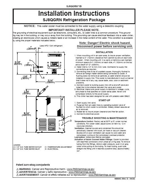
15
50930C
BUMPER
16
27303C
BASEPLATE
17
98777C
KIT - COMPR MTG/STUDS/CLIPS/GROMMETS
*INCLUDES RELAY & OVERLOAD. IF UNDER WARRANTY, REPLACE WITH SAME COMPRESSOR USED IN ORIGINAL ASSEMBLY. NOTE: All correspondence pertaining to any of the above water cooler or orders for repair parts MUST include model number and serial number of cooler, name and part number of replacement part.
RELEASE TUBE
6
ITEM NO.
115V ITEMIZED PARTS LIST
PART NO.
DESCRIPTION
1 0000000745 KIT - EVAPORATOR TANK ASSY
2
28478C
CABINET
3
98776C
KIT - CONDENSER/DRIER
4
98775C
KIT - FAN MTR/BLADE/SHROUD/SCREWS/NUTS
5
20282C
BRACKET - FAN MOUNTING
6
22300C
PANEL - REAR
7
55996C
IN-LINE STRAINER
8 1000001602 KIT - ELBOW 5/16" x 1/4" (3 PACK)
海尔空调产品说明书.pdf_1719195176.5938227
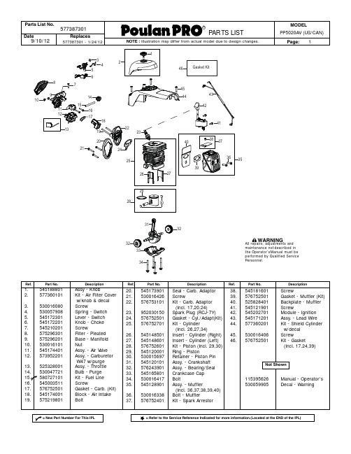
36. 530016338 37. 576752401
Description
Ref.
Seal - Carb. Adaptor
38.
Screw
39.
Kit - Carb. Adaptor
40.
(Incl. 17,20,24)
41.
Spark Plug (RCJ-7Y)
42.
Gasket - Cyl./Adapt(Kit) 43.
MODEL PP5020AV (US/CA N)
Page: 3
40 42
41
43
8 9 10
11
12
14
13
15 16
18 19 21 20
17
Ref.
1. 2. 3. 4. 5. 6. 7. 8. 9. 10. 11. 12. 13. 14. 15. 16. 17. 18. 19. 20. 21. 22.
Parts List No.
Date 9/10/12
577387301 Replaces
577387301- 1/24/12
R
PAR TS LIST
NOTE : Illustration may differ from actual model due to design changes.
1
4 3 2
29
28 27
26 25
23
24
22
Ref.
Part No.
23. 577180501 24. 545210201 25. 530016349 26. 545170901 27. 530016432 28. 578034501 29. 578034601 30. 525742101 31. 530015127 32. 530016134 33. 530021179 34. 545178201 35. 545211901 36. 530016080 37. 576744401 38. 530042095 39. 574394701 40. 525310201 41. 530069919 42. 530016432 43. 574394501
- 1、下载文档前请自行甄别文档内容的完整性,平台不提供额外的编辑、内容补充、找答案等附加服务。
- 2、"仅部分预览"的文档,不可在线预览部分如存在完整性等问题,可反馈申请退款(可完整预览的文档不适用该条件!)。
- 3、如文档侵犯您的权益,请联系客服反馈,我们会尽快为您处理(人工客服工作时间:9:00-18:30)。
内部资料注意保密
协议调试手册
(海尔空调三菱重工)
中兴通讯股份有限公司
版权所有,保留一切权利。
版权所有,侵权必究。
Copyright (C) 1997 by ZTE Co. Ltd..
All rights reserved.
设备说明
设备接口描述
(尽可能提供设备和接口图片,不同型号设备存在差别)
(如何判断有无接口板、接口板外观描述)
(接口类型、定义)
RS485电平;RS485方式 --> 白线+ 、黑线- 。
(波特率、数据位、校验位、停止位)
波特率9600、数据位8位、偶校验、起始/停止位1位
(操作步骤、拨码设置等)
监控接口板为独立安装在一个方形铁盒内。
地址拨码为SW1、SW2,SW1为十位数(取值范围为0,1,2,3,4),SW2为个位数(取值范围为0-9)。
将SW3-1设置为ON,可在没有遥控器情况下,只通过监控板控制空调。
指示灯红色LED G:表示接口板与空调通讯状态。
闪烁表示通讯正常;指示灯绿色LED R:表示通讯异常指示。
(特殊说明)
该接口板适用于海尔三菱重工8型机。
包括:RF75WD、RFD75WD、LF75WD、RF13WD、RFD13WD、LF13WD、RF73WDT、RFD73WDT、LF73WDT、RF25WD、RFD25WD、LF25WD、
RFU75WD、RFU13WD、RFU25WD。
调试方法
pcudebug.exe
发送:
接收:
(通讯是否存在时限要求、是否存在控制条件等)
通道表(包括物理通道和逻辑通道)
---AI通道---
AI通道17(双字节64) = 空调回风温度
---AO通道---
AO通道16(双字节503) = 空调温度设置点
---DI通道---
DI通道16(双字节3000) = 监控模块故障
DI通道18(双字节193) = 空调开关机状态(0-关机,1-开机)
DI通道19(双字节202) = 空调自动状态(0-否,1-是)
DI通道20(双字节197) = 空调除湿状态(0-否,1-是)
DI通道21(双字节195) = 空调制冷状态(0-否,1-是)
DI通道22(双字节200) = 空调送风状态(0-否,1-是)
DI通道23(双字节194) = 空调加热状态(0-否,1-是)
DI通道24(双字节204) = 弱风风量状态(0-否,1-是)
DI通道25(双字节203) = 急风风量状态(0-否,1-是)
DI通道26(双字节425) = 遥控器通信异常(0-否,1-是) DI通道27(双字节244) = 热传感器断线(0-否,1-是)
DI通道28(双字节426) = 吸入传感器断线(0-否,1-是) DI通道29(双字节333) = 暖房高压异常(0-否,1-是)
DI通道30(双字节427) = 开关异常(0-否,1-是)
DI通道31(双字节428) = 电压过低(0-否,1-是)
---DO通道---
DO通道162(双字节551) = 空调开机
DO通道163(双字节552) = 空调关机
DO通道164(双字节561) = 自动运行
DO通道165(双字节563) = 空调除湿
DO通道166(双字节560) = 空调制冷
DO通道167(双字节562) = 空调送风
DO通道168(双字节559) = 空调制热
DO通道169(双字节670) = 弱风风量
DO通道170(双字节669) = 急风风量
DO通道171(双字节553) = 异常复位
关键及特殊数据
(特殊接收函数处理)
常见故障
(被监控设备监控功能是否可靠)。