4N26MTA-V中文资料
4N36S1TB-V中文资料

6 PIN DIP PHOTOTRANSISTOR PHOTOCOUPLER4N3X Series H11AX SeriesFeatures:• 4N2X series: 4N25, 4N26, 4N27, 4N28 • 4N3X series: 4N35, 4N36, 4N37, 4N38• H11AX series: H11A1, H11A2, H11A3, H11A4, H11A5 • High isolation voltage between input and output (Viso=5000 V rms)• Creepage distance >7.6mm• Operating temperature up to +110°C • Compact dual-in-line package • Pb free and RoHS compliant. • UL approved (No. E214129) • VDE approved (No. 132249) • SEMKO approval pending • NEMKO approval pending • DEMKO approval pending • FIMKO approval pending • CSA approval pendingDescriptionThe 4N2X, 4N3X, H11AX series contains an infrared emitting diode optically coupled to a phototransistor. It is packaged in a 6-pin DIP package and available in wide-lead spacing and SMD option.Applications• Power supply regulators • Digital logic inputs • Microprocessor inputs1. Anode2. Cathode3. No Connection4. Emitter5. Collector6. BaseSchematic6 PIN DIP PHOTOTRANSISTOR PHOTOCOUPLER4N3X Series H11AX SeriesAbsolute Maximum Ratings (T a =25°C)Parameter Symbol Rating Unit Forward currentI F 50 mA Peak forward current (t = 10µs)I FM 1 A Reverse voltageV R 6 V 70 mW InputPower dissipation (T A = 25°C) Derating factor (above 100°C) P D 3.8 mW/°C Collector-Emitter voltage V CEO 80 V Collector-Base voltageV CBO 80 V Emitter-Collector voltage V ECO 7 V OutputEmitter-Base voltageV EBO 7 V 150 mWPower dissipation (T A = 25°C) Derating factor (above 100°C)P C 9.0mW/°CTotal power dissipation P tot 200 mW Isolation voltage *1 V iso 5000 Vrms Operating temperature T opr -55~+110 °C Storage temperature T stg -55~+125 °C Soldering temperature *2 T sol260 °CNotes*1 AC for 1 minute, R.H.= 40 ~ 60% R.H. In this test, pins 1, 2 & 3 are shorted together, and pins 4, 5 & 6 are shorted together. *2 For 10 seconds.6 PIN DIP PHOTOTRANSISTOR PHOTOCOUPLER4N3X Series H11AX SeriesElectrical Characteristics (T a =25°C unless specified otherwise)InputParameter Symbol Min. Typ.* Max. Unit ConditionForward voltage V F - 1.2 1.5 V I F = 10mA Reverse current I R - - 10 µA V R = 6V Input capacitanceC in-30-pFV = 0, f = 1MHzOutputParameter Symbol Min. Typ.* Max. Unit ConditionCollector-Base dark current I CBO - - 20 nA V CB = 10V - - 50V CE = 10V, IF=0mA Collector-Emitter darkcurrentI CEO - - 50nAV CE = 60V, IF=0mACollector-Emitter breakdown voltage BV CEO80 - - V I c =1mACollector-Base breakdown voltage BV CBO 80 -V I C =0.1mAEmitter-Collector breakdown voltage BV ECO 7 - - V I E =0.1mA Emitter-Basebreakdown voltage BV EBO7 - - V I E =0.1mACollector-Emitter capacitanceC CE - 8 - pF VCE=0V, f=1MHz* Typical values at T a = 25°C6 PIN DIP PHOTOTRANSISTOR PHOTOCOUPLER4N3X Series H11AX SeriesTransfer Characteristics (T a =25°C unless specified otherwise)Parameter Symbol Min. Typ.* Max. Unit Condition4N35, 4N36,4N37 100--H11A150 - - H11A5 30 - -4N25, 4N26, 4N38, H11A2, H11A3 20 - - Current transfer ratio4N27, 4N28, H11A4 CTR10--%I F = 10mA, V CE = 10V4N25, 4N26, 4N27, 4N28- - 0.5 I F = 50mA, I c = 2mA4N35, 4N36,4N37 - - 0.3H11A1, H11A2, H11A3, H11A4, H11A5 - - 0.4I F = 10mA, I c = 0.5mACollector-Emitter saturation voltage4N38V CE(sat) - - 1.0VI F = 20mA, I c = 4mA Isolation resistanceR IO 1011 - - ΩV IO = 500VdcInput-output capacitanceC IO- 0.2 - pF V IO = 0, f = 1MHz4N25, 4N26, 4N27, 4N28, H11A1, H11A2, H11A3,H11A4, H11A5- 3 10V CC = 10V, I F = 10mA,R L = 100Ω See Fig. 11Turn-on time4N35, 4N36, 4N37, 4N38 Ton- 10 12µsV CC = 10V, I C = 2mA,R L = 100Ω, See Fig. 114N25, 4N26, 4N27, 4N28, H11A1, H11A2, H11A3, H11A4- 3 10V CC = 10V, I F = 10mA, R L = 100Ω See Fig. 11Turn-off time4N35, 4N36, 4N37, 4N38Toff- 9 12µsV CC = 10V, I C = 2mA, R L = 100Ω, See Fig. 11* Typical values at T a = 25°C6 PIN DIP PHOTOTRANSISTOR PHOTOCOUPLER4N3X SeriesH11AX SeriesTypical Performance Curves6 PIN DIP PHOTOTRANSISTOR PHOTOCOUPLER4N3X SeriesH11AX SeriesFigure 11. Switching Time Test Circuit & WaveformsI FI CR LR INR BEV CCOutputInputInput PulseOutput Pulse10%90%t f t r t offt on6 PIN DIP PHOTOTRANSISTOR PHOTOCOUPLER4N3X Series H11AX SeriesOrder InformationPart Number4NXXY(Z)-VorH11AXY(Z)-VNoteXX = Part no. for 4NXX series (25, 26, 27, 28, 35, 36, 37 or 38) X = Part no. for H11AX series (1, 2, 3, 4, or 5) Y = Lead form option (S, S1, M or none) Z = Tape and reel option (TA, TB or none). V = VDE (optional)Option Description Packing quantityNone Standard DIP-665 units per tube M Wide lead bend (0.4 inch spacing)65 units per tube S (TA) Surface mount lead form + TA tape & reel option 1000 units per reel S (TB) Surface mount lead form + TB tape & reel option1000 units per reel S1 (TA) Surface mount lead form (low profile) + TA tape & reel option 1000 units per reel S1 (TB)Surface mount lead form (low profile) + TB tape & reel option1000 units per reel6 PIN DIP PHOTOTRANSISTOR PHOTOCOUPLER4N3X Series H11AX SeriesPackage Drawings(Dimensions in mm)Standard DIP TypeOption M Type6 PIN DIP PHOTOTRANSISTOR PHOTOCOUPLER4N3X Series H11AX SeriesOption S TypeOption S1 Type6 PIN DIP PHOTOTRANSISTOR PHOTOCOUPLER4N3X Series H11AX SeriesDevice MarkingNotesEL denotes Everlight4N35 denotes Device Number Y denotes 1 digit Year code WW denotes 2 digit Week code V denotes VDE (optional)EL 4N35YWWV6 PIN DIP PHOTOTRANSISTOR PHOTOCOUPLER4N3X Series H11AX SeriesTape dimensionsDimension No.A B Do D1 E F Dimension (mm) 10.4±0.1 7.52±0.1 1.5±0.1 1.5+0.1/-0 1.75±0.1 7.5±0.1Dimension No.Po P1 P2 t W K Dimension (mm) 4.0±0.15 16.0±0.1 2.0±0.1 0.35±0.03 16.0±0.2 4.5±0.1Option TAOption TBDirection of feed from reel Direction of feed from reel6 PIN DIP PHOTOTRANSISTOR PHOTOCOUPLER4N3X Series H11AX SeriesSolder Reflow Temperature Profile6 PIN DIP PHOTOTRANSISTOR PHOTOCOUPLER4N3X Series H11AX SeriesDISCLAIMER1. Above specification may be changed without notice. EVERLIGHT will reserve authority on material changefor above specification.2. When using this product, please observe the absolute maximum ratings and the instructions for use asoutlined in these specification sheets. EVERLIGHT assumes no responsibility for any damage resulting from use of the product which does not comply with the absolute maximum ratings and the instructions included in these specification sheets.3. These specification sheets include materials protected under copyright of EVERLIGHT Corporation.Please do not reproduce or cause anyone to reproduce them without EVERLIGHT’s consent.。
SVF4N65富佳维

SVF4N65T/F(G)/M/D 说明书4A、650V N沟道增强型场效应管描述SVF4N65T/F(G)/M/D N沟道增强型高压功率MOS场效应晶 体管采用士兰微电子的F-CellTM 平面高压VDMOS 工艺技术制 造。
先进的工艺及条状的原胞设计结构使得该产品具有较低的导 通电阻、优越的开关性能及很高的雪崩击穿耐量。
该产品可广泛应用于 AC-DC 开关电源,DC-DC 电源转换 器,高压 H 桥 PWM 马达驱动。
特点∗ ∗ ∗ ∗ ∗4A,650V,RDS(on)(典型值)=2.5Ω@VGS=10V 低栅极电荷量 低反向传输电容 开关速度快 提升了 dv/dt 能力命名规则产品规格分类产 品 名 称 SVF4N65T SVF4N65F SVF4N65FG SVF4N65M SVF4N65M SVF4N65D SVF4N65DTR 封装形式 TO-220-3L TO-220F-3L TO-220F-3L TO-251-3L TO-251D-3L TO-252-2L TO-252-2L 打印名称 SVF4N65T SVF4N65F SVF4N65FG SVF4N65M SVF4N65M SVF4N65D SVF4N65D 材料 无铅 无铅 无卤 无铅 无铅 无铅 无铅 包装形式 料管 料管 料管 料管 料管 料管 编带杭州士兰微电子股份有限公司版本号:1.12011.08.19 共10页 第1页SVF4N65T/F(G)/M/D 说明书极限参数(除非特殊说明,TC=25°C)参数名称 漏源电压 栅源电压 漏极电流 漏极脉冲电流 耗散功率(TC=25°C) - 大于 25°C 每摄氏度减少 单脉冲雪崩能量(注 1) 工作结温范围 贮存温度范围 TC=25°C TC=100°C 符号 VDS VGS ID IDM PD EAS TJ Tstg 100 0.80 参数范围 SVF4N65T SVF4N65F(G) 650 ±30 4.0 2.8 16 33 0.26 202 -55~+150 -55~+150 77 0.62 SVF4N65M/D 单位 V V A A W W/°C mJ °C °C热阻特性参数名称 芯片对管壳热阻 芯片对环境的热阻 符号 RθJC RθJA 参数范围 SVF4N65T 1.25 62.5 SVF4N65F(G) 3.79 120 SVF4N65M/D 1.62 110 单位 °C/W °C/W关键特性参数(除非特殊说明,TC=25°C)参数名称 漏源击穿电压 漏源漏电流 栅源漏电流 栅极开启电压 导通电阻 输入电容 输出电容 反向传输电容 开启延迟时间 开启上升时间 关断延迟时间 关断下降时间 栅极电荷量 栅极-源极电荷量 栅极-漏极电荷量 符号 BVDSSB测试条件 VGS=0V, ID=250µA VDS=650V,VGS=0V VGS=±30V,VDS=0V VGS= VDS,ID=250µA VGS=10V,ID=2A VDS=25V,VGS=0V, f=1.0MHZ VDD=325V,ID=4.0A, RG=25Ω (注 2,3) VDS=520V,ID=4.0A, VGS=10V (注 2,3)最小值 650 --2.0 ------------典型值 ----2.5 464 54 1.32 16.6 37.33 18.0 19.2 8.03 2.57 3.03最大值 -1.0 ±100 4.0 2.7 -----------单位 V µA nA V ΩIDSS IGSS VGS(th) RDS(on) Ciss Coss Crss td(on) tr td(off) tf Qg Qgs QgdpFnsnC杭州士兰微电子股份有限公司版本号:1.12011.08.19 共10页 第2页SVF4N65T/F(G)/M/D 说明书源-漏二极管特性参数参数名称 源极电流 源极脉冲电流 源-漏二极管压降 反向恢复时间 反向恢复电荷 注: 1. 2. 3. L=30mH,IAS=3.36A,VDD=150V,RG=25Ω,开始温度 TJ=25°C; 脉冲测试: 脉冲宽度≤300μs,占空比≤2%; 基本上不受工作温度的影响。
PT4126A中文资料

—
500
15
23
1.3 1.6 4.0 5.0 75.0 ±1.5 ±50 — ±1.0 ±33 ±1.0 ±33 — — — — — — — — — — — — — 700 900 —
7.0 (2) +0.8 – 50 — 200 — — — +85 (3) +125
0.1A/µs, load step 50% to 100% Iomax
Vo over/undershoot
Vo ≥ 5.0Vge
Vo ≥ 12.0V Vo ≤ 5.2V
Referenced to –Vin (pin 2)
pins 1 & 2 connected
Mechanical Shock
Mechanical Vibration
Weight Flammability
Io
Vin Vo tol
Regtemp Regline
Regload
∆Votot
η
Vr
ttr ∆Vtr Isc ƒs UVLO VIH VIL IIL Iin standby Cin Cout
Ta Ts MTBF — — — —
Over Vin range
Vo = 15V Vo = 12V Vo =5.0V Vo ≤ 3.3V
Over Io Range
Vo ≥5.0V
Vo ≤3.3V
–40° ≤Ta ≤ +85°C
Over Vin range
Vo ≥5.0V
Vo ≤3.3V
Over Io range
Description
The PT4120 power modules are a series of isolated DC/DC converters housed a lowprofile package. Rated for 20 watts or 5A, the series includes standard output voltages ranging from as low as 1.5VDC to 15VDC. The output may be adjusted ±10% of nominal. These converters are ideal for Telecom, Industrial, Computer, and other distributed power applications that require input-tooutput isolation.
4N60中文资料
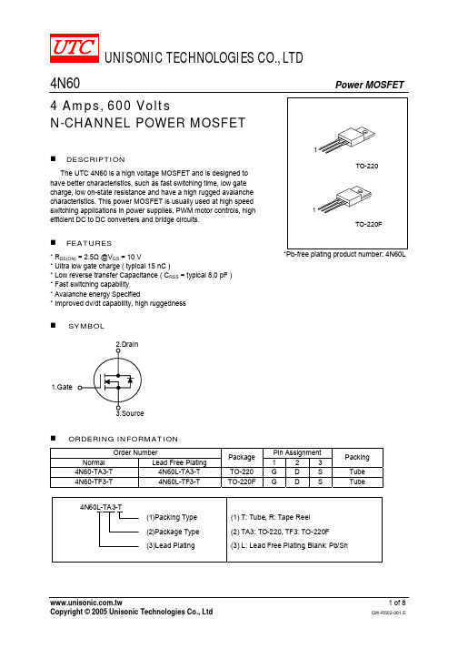
UNISONIC TECHNOLOGIES CO., LTD4N60 Power MOSFET4 Amps, 600 VoltsN-CHANNEL POWER MOSFETDESCRIPTIONThe UTC 4N60 is a high voltage MOSFET and is designed to have better characteristics, such as fast switching time, low gate charge, low on-state resistance and have a high rugged avalanche characteristics. This power MOSFET is usually used at high speed switching applications in power supplies, PWM motor controls, high efficient DC to DC converters and bridge circuits.FEATURES* RDS(ON) = 2.5Ω @V GS = 10 V* Ultra low gate charge ( typical 15 nC )* Low reverse transfer Capacitance ( C RSS = typical 8.0 pF ) * Fast switching capability * Avalanche energy Specified* Improved dv/dt capability, high ruggednessSYMBOL1.GateTO-22011TO-220F*Pb-free plating product number: 4N60LORDERING INFORMATIONOrder Number Pin AssignmentNormalLead Free Plating Package 1 2 3 Packing4N60-TA3-T 4N60L-TA3-T TO-220 G D S Tube 4N60-TF3-T 4N60L-TF3-T TO-220F G D S TubeABSOLUTE MAXIMUM RATINGS (T C = 25℃, unless otherwise specified)PARAMETER SYMBOL RATINGS UNITDrain-Source Voltage V DSS 600 V Gate-Source Voltage V GSS ±30 V Avalanche Current - (Note 1) I AR 4.4 AT C = 25°C 4.0 AContinuous Drain CurrentT C = 100°C I D 2.8 APulsed Drain Current, T P Limited by T JMAX - (Note 1) I DM 16 A Avalanche Energy, Single Pulsed (Note 2) E AS 260 mJ Avalanche Energy, Repetitive, Limited by T JMAX E AR 10.6 mJ Peak Diode Recovery dv/dt (Note 3) dv/dt 4.5 V/ns Power Dissipation (T C = 25°C) P D 106 W Junction Temperature T J +150 Storage Temperature T STG -55 ~ +150Note Absolute maximum ratings are those values beyond which the device could be permanently damaged.Absolute maximum ratings are stress ratings only and functional device operation is not implied.THERMAL DATAPARAMETER SYMBOL MIN TYP MAX UNITJunction-to-Ambient θJA 62.5 °C/W Junction-to-Case θJC 3 °C/W Case-to-Sink θCS 0.5 °C/WELECTRICAL CHARACTERISTICS (T C =25℃, unless otherwise specified)PARAMETER SYMBOL TEST CONDITIONS MIN TYP MAX UNITOff CharacteristicsDrain-Source Breakdown Voltage BV DSS V GS = 0 V, I D = 250 µA 600V V DS = 600 V, V GS = 0 V10µA Drain-Source Leakage Current I DSSV DS = 480 V, T C = 125°C100µA Forward V GS = 30 V, V DS = 0 V100nA Gate-Source Leakage CurrentReverse I GSSV GS = -30 V, V DS = 0 V-100nA Breakdown Voltage Temperature CoefficientBV DSS /△T J I D = 250 µA, Referenced to 25°C 0.6 V/ On Characteristics Gate Threshold VoltageV GS(TH)V DS = V GS , I D = 250 µA 2.0 4.0V Drain-Source On-State Resistance R DS(ON) V GS = 10 V, I D = 2.2 A2.5ΩForward Transconductance g FSV DS = 50 V, I D = 2.2 A (Note 4)4.0SDynamic Characteristics Input Capacitance C ISS 520 670pFOutput CapacitanceC OSS 70 90pFReverse Transfer Capacitance C RSSV DS = 25 V, V GS = 0 V, f = 1MHz 8 11pF Switching Characteristics Turn-On Delay Time t D(ON) 13 35nsTurn-On Rise Time t R 45 100ns Turn-Off Delay Time t D(OFF) 25 60nsTurn-Off Fall Time t FV DD = 300V, I D = 4.0 A, R G = 25Ω(Note 4, 5) 35 80ns Total Gate Charge Q G 15 20nCGate-Source Charge Q GS 3.4 nCGate-Drain ChargeQ DDV DS = 480V,I D = 4.0A, V GS = 10 V(Note 4, 5)7.1 nCELECTRICAL CHARACTERISTICS(Cont.)PARAMETER SYMBOL TEST CONDITIONS MIN TYP MAX UNITSource- Drain Diode Ratings and Characteristics Drain-Source Diode Forward Voltage V SD V GS = 0 V, I S = 4.4 A 1.4VMaximum Continuous Drain-SourceDiode Forward CurrentI S 4.4AMaximum Pulsed Drain-Source DiodeForward CurrentI SM 17.6AReverse Recovery Time t RR 250 ns Reverse Recovery Charge Q RR V GS = 0 V, I S = 4.4 A,dI F /dt = 100 A/µs (Note 4) 1.5 µCNotes: 1. Repetitive Rating : Pulse width limited by T J2. L = 25mH, I AS = 4.4A, V DD = 50V, R G = 25 Ω, Starting T J = 25°C3. I SD ≤4.4A, di/dt ≤200A/µs, V DD ≤ BV DSS , Starting T J = 25°C 4. Pulse Test: Pulse width ≤ 300µs, Duty cycle ≤ 2%5. Essentially independent of operating temperatureTEST CIRCUITS AND WAVEFORMSV DDV GS (Driver)I SD (D.U.T.)Body DiodeForward Voltage DropV DS(D.U.T.)Fig. 1A Peak Diode Recovery dv/dt Test CircuitFig. 1B Peak Diode Recovery dv/dt WaveformsTEST CIRCUITS AND WAVEFORMS (Cont.)R LDDV DS90%10%V GStFig. 2A Switching Test Circuit Fig. 2B Switching WaveformsFig. 3A Gate Charge Test CircuitFig. 3B Gate Charge Waveform10VLV DDI ASFig. 4A Unclamped Inductive Switching Test Circuit Fig. 4B Unclamped Inductive Switching WaveformsTYPICAL CHARACTERISTICS-100D r a i n -S o u rc e B r e a kd o w n V o l t a ge , B V D S S (N o r m a l i z e d )Junction Temperature , T J (℃)502001001501.201.11.00.90.8Breakdown Voltage Variation vs .Temperature-100D r a i n -S o u r ce O n -R e s i s t a n c e , R D S (O N ) (N o r m a l i z e d )Junction Temperature , T J (℃)-50502001001503.002.01.00.50.01.52.5On-Resistance Junction Temperature10Drain-Source Voltage , V DS (V)D r a i n C u r r e n t , I D (A )1001011000Maximum Safe Operating AreaD r a i n C u r r e n t , I D (A )Case Temperature , T C (℃)751000125502512345Maximum Drain Current vs . CaseTemperature100.11Drain -to-Source Voltage , V DS (V)D r a i n C u r r e n t , I D (A )On-State Characteristics2Gate-Source Voltage , V GS (V)D r a i n C u r r e n t , I D (A )Transfer Characteristics 46810100.1TYPICAL CHARACTERISTICS(Cont.)D r a i n -S o u r c e O n -R e s i s t a n c e , R D S (O N ) (o h m )Drain Current, I D (A)24On-Resistance Variation vs . DrainCurrent and Gate Voltage 6810120.2Source-Drain Voltage , V SD (V)On State Current vs. Allowable CaseTemperature1.80.40.60.81.01.2 1.61.4120000.1Drain-SourceVoltage , V DS (V)C a p a c i t a n c e (p F )1000200110800600Capacitance Characteristics(Non-Repetitive)G a t e -S o u r c e V o l t a g e , V G S (V )Total Gate Charge , Q G (nC)515258101210642020Gate Charge Characteristics400T h e r m a l R e s p o n s e , θJ C (t )Square Wave Pulse Duration , t 1(sec)Transient Thermal ResponseCurve 00P D (w )T C (°C)2040204080100120Power Dissipation606080100120140160。
IPS226V-PN 产品说明说明书

-PNIPS226VMONITEURLED IPSMONITEURUne Technologie étendue au servicede la Qualité d’image !•Dalle IPS à Rétro-éclairage LED•1920x1080•HDMI, VGA, DVI•5ms (GTG)•Smart + Package (Dual Web, Cinema Mode)•Contrôle étendu des couleurs•Basse Consommation: EPA 5.0 CertificationMONITEURType de dalleTaille écran/imageFormatPitchLuminositéTaux de contraste (original) Taux de contraste (DFC) Angle de vision (H/V) Temps de réponse (GTG) RésolutionBacklight typeIPS21.5’’pouces (55cm)16:90.248mm*0.248mm250cd/m²1000:15M:1178/1785ms1920*1080LEDULCULSEMKOFCC-BCEEnergy Star (EPA 5.0)VistaTUV-Type GSISO13406-2TCO-03TCO-99OuiOuiOuiOuiOuiOuiPremiumOuiNonNonNonD-Sub DVI-D OuiOuiCâble d'alimentationCâble VGAOuiOuiOSDNombre de languesNorme VESABase détachableInclinaisonPied réglable en hauteurPied rotatif (Pivot)Mise en à platCouleurKensingtonFLATRON f EngineHDCP4:3 in Wideez-Zoomingfonction SMARTBouton de contrôle (Nombre de touche) Couleur LEDOui15Oui (75x75)OuiOui / -5°~ 15°NonNonNon Noir / Blanc / Violet-OuiOui-NonOui7Blanche100-240 VoltsConsommation (mode normale) Consommation (mode veille) Consommation (mode arrêt)Fréquence (H/V)Oui35W0.5W0.5W 30~83kHz / 56~75HzHDMIPC Audio InSortie casqueUSB 2.0Composite (RCA) Composante (RCA)Haut-parleurs invisibles (Watts)OuiNonNonNonNonNonNonoucid’amélioration,êtremodifiéessanspréavis.Câble DVICâble vidéoBatteriesTélécommandeGuide d'installation rapideManuel sur CDGENCOD (IPS226VGENCOD (IPS226V--PN.AEU)En optionNonNonNonOui-8808992987550INFORMATIONS LOGISTIQUES Dimensions moniteur sans pied (LxHxP en mm)Dimensions moniteur avec pied (LxHxP en mm) Dimensions de l’emballage (LxlxP en mm)Poids net moniteur sans pied en kgPoids net moniteur avec pied en kgPoids net moniteur avec pied + emballageCescaractéristiquessontsoumisesàtitreindicatifetpeuvent,dansuns514.8 x 332.2 x 40.4514.8 x 403 x 230583 x 454 x 1372.973.495.5LG Electronics FranceParis Nord II -117, avenue des Nations -BP 59372 Villepinte -95942 ROISSY CDG CEDEX -Tél. : 01 49 89 89 49 -Fax : 01 49 89 88 69 Service client : Pour plus d’informations : /fr。
4N26中文资料
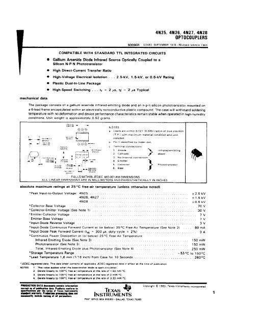
IMPORTANT NOTICETexas Instruments and its subsidiaries (TI) reserve the right to make changes to their products or to discontinue any product or service without notice, and advise customers to obtain the latest version of relevant information to verify, before placing orders, that information being relied on is current and complete. All products are sold subject to the terms and conditions of sale supplied at the time of order acknowledgement, including those pertaining to warranty, patent infringement, and limitation of liability.TI warrants performance of its semiconductor products to the specifications applicable at the time of sale in accordance with TI’s standard warranty. Testing and other quality control techniques are utilized to the extent TI deems necessary to support this warranty. Specific testing of all parameters of each device is not necessarily performed, except those mandated by government requirements.CERTAIN APPLICATIONS USING SEMICONDUCTOR PRODUCTS MAY INVOLVE POTENTIAL RISKS OF DEATH, PERSONAL INJURY, OR SEVERE PROPERTY OR ENVIRONMENTAL DAMAGE (“CRITICAL APPLICATIONS”). TI SEMICONDUCTOR PRODUCTS ARE NOT DESIGNED, AUTHORIZED, OR WARRANTED TO BE SUITABLE FOR USE IN LIFE-SUPPORT DEVICES OR SYSTEMS OR OTHER CRITICAL APPLICATIONS. INCLUSION OF TI PRODUCTS IN SUCH APPLICATIONS IS UNDERSTOOD TO BE FULLY AT THE CUSTOMER’S RISK.In order to minimize risks associated with the customer’s applications, adequate design and operating safeguards must be provided by the customer to minimize inherent or procedural hazards.TI assumes no liability for applications assistance or customer product design. TI does not warrant or represent that any license, either express or implied, is granted under any patent right, copyright, mask work right, or other intellectual property right of TI covering or relating to any combination, machine, or process in which such semiconductor products or services might be or are used. TI’s publication of information regarding any third party’s products or services does not constitute TI’s approval, warranty or endorsement thereof.Copyright © 1998, Texas Instruments Incorporated。
2464-AWM-80C-300V
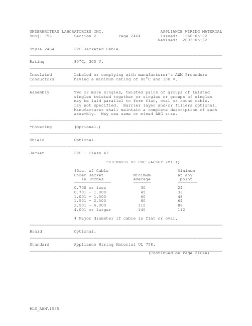
Subj. 758 Section 2 Page 2464 Issued: 1968-05-02Revised: 2003-05-02Style 2464 PVC Jacketed Cable.______________________________________________________________________________ Rating 80°C, 300 V.______________________________________________________________________________ Insulated Labeled or complying with manufacturer's AWM Procedure Conductors having a minimum rating of 80°C and 300 V.______________________________________________________________________________ Assembly Two or more singles, twisted pairs of groups of twistedsingles twisted together or singles or groups of singlesmay be laid parallel to form flat, oval or round cable.Lay not specified. Barrier layer and/or fillers optional.Manufacturer shall maintain a complete description of eachassembly. May use same or mixed AWG size.______________________________________________________________________________ *Covering (Optional.)______________________________________________________________________________ Shield Optional.______________________________________________________________________________ Jacket PVC - Class 43THICKNESS OF PVC JACKET (mils)#Dia. of Cable MinimumUnder Jacket Minimum at anyin Inches Average point0.700 or less 30 240.701 - 1.000 45 361.001 - 1.500 60 481.501 -2.500 80 642.501 - 4.000 110 884.001 or larger 140 112# Major diameter if cable is flat or oval.______________________________________________________________________________ Braid Optional.______________________________________________________________________________ Standard Appliance Wiring Material UL 758.______________________________________________________________________________(Continued on Page 2464A)Subj. 758 Section 2 Page 2464A Issued: 1968-05-02Revised: 2003-05-02 Instructions Detailed Examination of the cable assembly and jacket.to UL Physical Properties of Jacket.Representative Dielectric Strength Test, 1500 Volts (shielded cable only).The designation of all Styles of the individual conductorsused making up the cable assembly shall be available, andthe UL Representative’s tag shall indicate if the Style islabeled or not. If they are not labeled, the appropriateFollow-Up Tests shall be conducted.______________________________________________________________________________ UL (4) Detailed Examination.Counter-Check (4) Physical Properties of Jacket.Program (4) Heat Shock on Jacket.(4) Cold Bend on Completed Cable.(4) Deformation on Jacket, Class 43.(12) Cable Flame Test on Completed Cable.If the insulated styles are not labeled, the appropriateFollow-Up Tests shall be conducted.______________________________________________________________________________ Marking General.______________________________________________________________________________ Use Internal wiring or external interconnection of electronicequipment (such as desk-type calculators, dictatingmachines, or x-ray equipment).。
RFP4N06中文资料
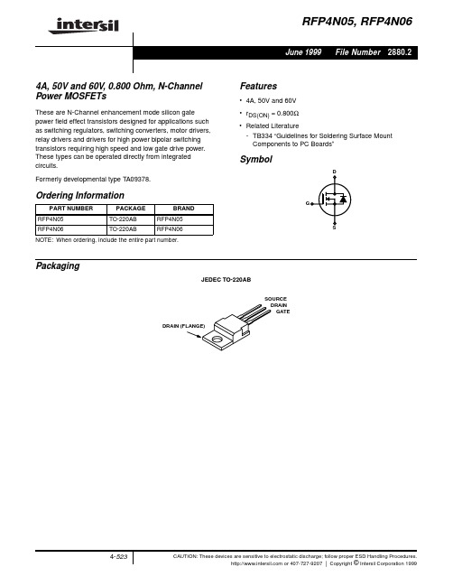
RFP4N05
RFP4N06
UNITS
Drain to Source Voltage (Note 1) . . . . . . . . . . . . . . . . . . . . . . . . . . . . . . . VDSS Drain to Gate Voltage (RGS = 20kΩ) (Note 1). . . . . . . . . . . . . . . . . . . . . VDGR Drain Current, RMS Continuous . . . . . . . . . . . . . . . . . . . . . . . . . . . . . . . . . . ID
COSS
-
CRSS
-
RθJC
-
TYP MAX UNITS
-
-
V
-
-
V
-
4
V
-
1
µA
-
25
µA
-
±100 nA
-
0.800
Ω
-
3.2
V
6
15
ns
14
30
ns
16
30
ns
14
25
ns
-
200
pF
-
85
pF
-
30
pF
-
5
oC/W
Source to Drain Diode Specifications
PARAMETER
-40oC
25oC
125oC
1
0
0
2
4
6
8
10
VGS, GATE TO SOURCE VOLTAGE (V)
4N25中文资料_数据手册_参数
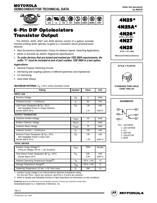
SEMICONDUCTOR TECHNICAL DATA
GlobalOptoisolator™
6-Pin DIP Optoisolators Transistor Output
The 4N25/A, 4N26, 4N27 and 4N28 devices consist of a gallium arsenide infrared emitting diode optically coupled to a monolithic silicon phototransistor detector. • Most Economical Optoisolator Choice for Medium Speed, Switching Applications • Meets or Exceeds All JEDEC Registered Specifications • To order devices that are tested and marked per VDE 0884 requirements, the
1
1.4
TA = –55°C
1.2
25°C
1
100°C
1
10
100
1000
IF, LED FORWARD CURRENT (mA)
Figure 1. LED Forward Voltage versus Forward Current
0.1
0.01
0.5 1 2
5 10 20
50
IF, LED INPUT CURRENT (mA)
SCHEMATIC
1
6
2
5
3
4
PIN 1. LED ANODE 2. LED CATHODE 3. N.C. 4. EMITTER 5. COLLECTOR 6. BASE
4N26.S中文资料
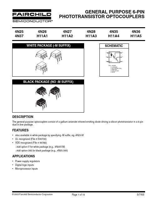
4N25 4N37
4N26 H11A1
4N27 H11A2
4N28 H11A3
4N35 H11A4
4N36 H11A5
TYPICAL PERFORMANCE CURVES
VF - FORWARD VOLTAGE (V)
Fig. 1 LED Forward Voltage vs. Forward Current (Black Package)
CTR
H11A3
%
4N27
4N28
10
H11A4
(IF = 10 mA, VCE = 10 V, TA = -55°C)
4N35
4N36
40
4N37
(IF = 10 mA, VCE = 10 V, TA = +100°C)
4N35
4N36
40
4N37
4N25
(IC = 2 mA, IF = 50 mA)
DC Characteristic
Test Conditions
Symbol Device Min
Typ*
Max
Unit
4N35
4N36
100
4N37
H11A1 50
H11A5 30
(IF = 10 mA, VCE = 10 V)
4N25
4N26 H11A2
20
Current Transfer Ratio, Collector to Emitter
Symbol
VF IR
BVCEO BVCBO BVECO
ICEO ICBO CCE
Min
Typ*
Max
Unit
1.18
1.50
施耐德47236 Masterpact MT12 -1250 A -4极 抽屉式断路器本体数据表
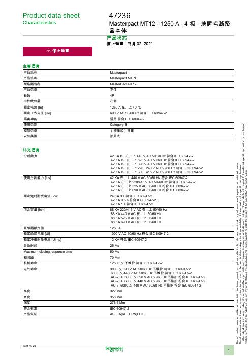
Product data sheetCharacteristics47236Masterpact MT12 - 1250 A - 4 极 - 抽屉式断路器本体产品状态停止销售 : 四月 02, 2021主要信息产品系列Masterpact 产品名称Masterpact MT N 断路器名称MasterPact NT12产品类型本体极数4P 中性线位置左侧额定电流 [In]1250 A 在…上 40 °C额定工作电压 [Ue]690 V AC 50/60 Hz 符合 IEC 60947-2隔离功能适用 符合 IEC 60947-2使用类别Category B 控制类型(按压式)按钮安装类型抽屉式补充信息分断能力42 KA Icu 在…上 440 V AC 50/60 Hz 符合 IEC 60947-2 42 KA Icu 在…上 525 V AC 50/60 Hz 符合 IEC 60947-2 42 KA Icu 在…上 690 V AC 50/60 Hz 符合 IEC 60947-242 KA Icu 在…上 220...240 V AC 50/60 Hz 符合 IEC 60947-2 42 KA Icu 在…上 380...415 V AC 50/60 Hz 符合 IEC 60947-2使用分断能力 [Ics]42 KA 在…上 440 V AC 50/60 Hz 符合 IEC 60947-242 KA 在…上 220/415 V AC 50/60 Hz 符合 IEC 60947-2 42 KA 在…上 525 V AC 50/60 Hz 符合 IEC 60947-2 42 KA 在…上 690 V AC 50/60 Hz 符合 IEC 60947-2额定短时耐受电流 [Icw]24 KA 3 s 符合 IEC 60947-2 42 KA 0.5 s 符合 IEC 60947-2 42 KA 1 s 符合 IEC 60947-2闭合容量 [Icm]88 KA 220/415 V AC 在…上 50/60 Hz 88 KA 440 V AC 在…上 50/60 Hz 88 KA 525 V AC 在…上 50/60 Hz 88 KA 690 V AC 在…上 50/60 Hz 互感器额定值1250 A额定绝缘电压 [Ui]1000 V AC 50/60 Hz 符合 IEC 60947-2额定冲击耐受电压 [Uimp]12 KV 符合 IEC 60947-2分断时间25 Ms Maximum closing response time 50 Ms 相间距70 Mm机械寿命12500 次 不维护 符合 IEC 60947-2电气寿命3000 次 690 V AC 50/60 Hz 不维护 符合 IEC 60947-2 6000 次 440 V AC 50/60 Hz 不维护 符合 IEC 60947-2AC-23A: 3000 次 690 V AC 50/60 Hz 不维护 符合 IEC 60947-2 AC-23A: 6000 次 440 V AC 50/60 Hz 不维护 符合 IEC 60947-2 AC-3: 6000 次 440 V AC 50/60 Hz 不维护 符合 IEC 60947-2高度322 Mm 宽度358 Mm 深度276.5 Mm 符合标准IEC 60947-2产品认证ASEFA[RETURN]LCIET h e i n f o r m a t i o n p r o v i d e d i n t h i s d o c u m e n t a t i o n c o n t a i n s g e n e r a l d e s c r i p t i o n s a n d /o r t e c h n i c a l c h a r a c t e r i s t i c s o f t h e p e r f o r m a n c e o f t h e p r o d u c t s c o n t a i n e d h e r e i n .T h i s d o c u m e n t a t i o n i s n o t i n t e n d e d a s a s u b s t i t u t e f o r a n d i s n o t t o b e u s e d f o r d e t e r m i n i n g s u i t a b i l i t y o r r e l i a b i l i t y o f t h e s e p r o d u c t s f o r s p e c i f i c u s e r a p p l i c a t i o n s .I t i s t h e d u t y o f a n y s u c h u s e r o r i n t e g r a t o r t o p e r f o r m t h e a p p r o p r i a t e a n d c o m p l e t e r i s k a n a l y s i s , e v a l u a t i o n a n d t e s t i n g o f t h e p r o d u c t s w i t h r e s p e c t t o t h e r e l e v a n t s p e c i f i c a p p l i c a t i o n o r u s e t h e r e o f .N e i t h e r S c h n e i d e r E l e c t r i c I n d u s t r i e s S A S n o r a n y o f i t s a f f i l i a t e s o r s u b s i d i a r i e s s h a l l b e r e s p o n s i b l e o r l i a b l e f o r m i s u s e o f t h e i n f o r m a t i o n c o n t a i n e d h e r e i n .环境污染等级 3 符合 IEC 60664-1运行温度-25…70 °C贮存环境温度-40…85 °C包装单位Unit Type of Package 1PCENumber of Units in Package 11Package 1 Height 5.5 CmPackage 1 Width23 CmPackage 1 Length12.5 Cm Package 1 Weight 4.648 Kg合同保修保修单18 months Product Life Status :End of commercialisation。
4046中文资料
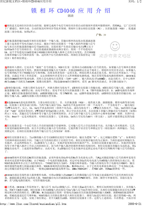
锁 相 环 CD4046 应 用 介 绍朗清锁相的意义是相位同步的自动控制,能够完成两个电信号相位同步的自动控制闭环系统叫做锁相环,简称PLL。
它广泛应用于广播通信、频率合成、自动控制及时钟同步等技术领域。
锁相环主要由相位比较器(PC)、压控振荡器(VCO)。
低通滤波器三部分组成,如图1所示。
广告:>>上建立起来的平均电压Ud大小决定。
施加于相位比较器另一个输入端的外部输入信号Ui与来自压控振荡器的输出信号Uo相比较,比较结果产生的误差输出电压UΨ正比于Ui和Uo两个信号的相位差,经过低通滤波器滤除高频分量后,得到一个平均值电压Ud。
这个平均值电压Ud朝着减小VCO输出频率和输入频率之差的方向变化,直至VCO输出频率和输入信号频率获得一致。
这时两个信号的频率相同,两相位差保持恒定(即同步)称作相位锁定。
当锁相环入锁时,它还具有“捕捉”信号的能力,VCO可在某一范围内自动跟踪输入信号的变化,如果输入信号频率在锁相环的捕捉范围内发生变化,锁相环能捕捉到输人信号频率,并强迫VCO锁定在这个频率上。
锁相环应用非常灵活,如果输入信号频率f1不等于VCO输出信号频率f2,而要求两者保持一定的关系,例如比例关系或差值关系,则可以在外部加入一个运算器,以满足不同工作的需要。
过去的锁相环多采用分立元件和模拟电路构成,现在常使用集成电路的锁相环,CD4046是通用的CMOS锁相环集成电路,其特点是电源电压范围宽(为3V-18V),输入阻抗高(约100MΩ),动态功耗小,在中心频率f0为10kHz下功耗仅为600μW,属微功耗器件。
图2是CD4046的引脚排列,采用 16 脚双列直插式,各引脚功能如下:1脚相位输出端,环路人锁时为高电平,环路失锁时为低电平。
2脚相位比较器Ⅰ的输出端。
3脚比较信号输入端。
4脚压控振荡器输出端。
5脚禁止端,高电平时禁止,低电平时允许压控振荡器工作。
6、7脚外接振荡电容。
8、16脚电源的负端和正端。
4N25V中文资料

88
Rev. A4, 11–Jan–99
元器件交易网
4N25(G)V/ 4N35(G)V Series
Vishay Telefunken Maximum Safety Ratings (according to VDE 0884) see figure 1
This device is used for protective separation against electrical shock only within the maximum safety ratings. This must be ensured by using protective circuits in the applications.
Absolute Maximum Ratings
Input (Emitter)
Parameter Reverse voltage Forward current Forward surge current Power dissipation Junction temperature Test Conditions Symbol VR IF IFSM PV Tj Value 5 60 3 100 125 Unit V mA A mW °C
B 6
C 5
E 4
VDE Standards
These couplers perform safety functions according to the following equipment standards:
1 2 A (+) C (–) 3 n.c.
95 10805
D VDE 0884
Optocoupler for electrical safety requirements
MEMORY存储芯片MTA36ASF4G72PZ-2G3B1中文规格书
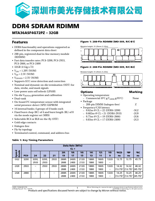
DDR4 SDRAM RDIMM MTA36ASF4G72PZ – 32GBFeatures•DDR4 functionality and operations supported asdefined in the component data sheet•288-pin, registered dual in-line memory module(RDIMM)•Fast data transfer rates: PC4-3200, PC4-2933,PC4-2666, or PC4-2400•32GB (4 Gig x 72)•V DD = 1.20V (NOM)•V PP = 2.5V (NOM)•V DDSPD = 2.5V (NOM)•Supports ECC error detection and correction•Nominal and dynamic on-die termination (ODT) fordata, strobe, and mask signals•Low-power auto self refresh (LPASR)•On-die V REFDQ generation and calibration•Dual-rank•On-board I 2C temperature sensor with integratedserial presence-detect (SPD) EEPROM•16 internal banks; 4 groups of 4 banks each•Fixed burst chop (BC) of 4 and burst length (BL) of 8via the mode register set (MRS)•Selectable BC4 or BL8 on-the-fly (OTF)•Gold edge contacts•Halogen-free•Fly-by topology•Terminated control, command, and address busFigure 1: 288-Pin RDIMM (MO-309, R/C-B1)Figure 2: 288-Pin RDIMM (MO-309, R/C-B2)Options Marking •Operating temperature –Commercial (0°C ≤ T OPER ≤ 95°C)None •Package –288-pin DIMM (halogen-free)Z •Frequency/CAS latency –0.62ns @ CL = 22 (DDR4-3200)-3G2–0.682ns @ CL = 21 (DDR4-2933)-2G9–0.75ns @ CL = 19 (DDR4-2666)-2G6–0.83ns @ CL = 17 (DDR4-2400)-2G3Table 1: Key Timing ParametersCCMTD-1725822587-9795asf36c4gx72pz.pdf - Rev. J 7/19 EN 1Micron Technology, Inc. reserves the right to change products or specifications without notice.© 2014 Micron Technology, Inc. All rights reserved.Products and specifications discussed herein are subject to change by Micron without notice.Temperature Sensor with SPD EEPROM Operation Thermal Sensor OperationsThe integrated thermal sensor continuously monitors the temperature of the module PCB directly below the device and updates the temperature data register. Temperature data may be read from the bus host at any time, which provides the host real-time feed-back of the module's temperature. Multiple programmable and read-only temperature registers can be used to create a custom temperature-sensing solution based on system requirements and JEDEC JC-42.2.EVENT_n PinThe temperature sensor also adds the EVENT_n pin (open-drain), which requires a pull-up to V DDSPD . EVENT_n is a temperature sensor output used to flag critical events that can be set up in the sensor’s configuration registers. EVENT_n is not used by the serial presence-detect (SPD) EEPROM.EVENT_n has three defined modes of operation: interrupt, comparator, and TCRIT. In interrupt mode, the EVENT_n pin remains asserted until it is released by writing a 1 to the clear event bit in the status register. In comparator mode, the EVENT_n pin clears itself when the error condition is removed. Comparator mode is always used when the temperature is compared against the TCRIT limit. In TCRIT only mode, the EVENT_n pin is only asserted if the measured temperature exceeds the TCRIT limit; it then re-mains asserted until the temperature drops below the TCRIT limit minus the TCRIT hysteresis.SPD EEPROM OperationDDR4 SDRAM modules incorporate SPD. The SPD data is stored in a 512-byte, JEDEC JC-42.4-compliant EEPROM that is segregated into four 128-byte, write-protectable blocks. The SPD content is aligned with these blocks as shown in the table below.The first 384 bytes are programmed by Micron to comply with JEDEC standard JC-45,"Appendix X: Serial Presence Detect (SPD) for DDR4 SDRAM Modules." The remaining 128 bytes of storage are available for use by the customer.The EEPROM resides on a two-wire I 2C serial interface and is not integrated with the memory bus in any manner. It operates as a slave device in the I 2C bus protocol, with all operations synchronized by the serial clock. Transfer rates of up to 1 MHz are achieva-ble at 2.5V (NOM).Micron implements reversible software write protection on DDR4 SDRAM-based mod-ules. This prevents the lower 384 bytes (bytes 0 to 383) from being inadvertently pro-grammed or corrupted. The upper 128 bytes remain available for customer use and are unprotected.32GB (x72, ECC, DR) 288-Pin DDR4 RDIMM Temperature Sensor with SPD EEPROM OperationCCMTD-1725822587-9795asf36c4gx72pz.pdf - Rev. J 7/19 EN 19Micron Technology, Inc. reserves the right to change products or specifications without notice.© 2014 Micron Technology, Inc. All rights reserved.Registering Clock Driver SpecificationsTable 21: Registering Clock Driver Electrical CharacteristicsNote: 1.Timing and switching specifications for the register listed are critical for proper opera-tion of DDR4 SDRAM RDIMMs. These are meant to be a subset of the parameters for the specific device used on the module. See the JEDEC RCD01 specification for complete op-erating electrical characteristics. Registering clock driver parametric values are specified for device default control word settings, unless otherwise stated. The RC0A control word setting does not affect parametric values.32GB (x72, ECC, DR) 288-Pin DDR4 RDIMM Registering Clock Driver SpecificationsCCMTD-1725822587-9795asf36c4gx72pz.pdf - Rev. J 7/19 EN 28Micron Technology, Inc. reserves the right to change products or specifications without notice.© 2014 Micron Technology, Inc. All rights reserved.Table 23: Temperature Sensor and EEPROM Serial Interface Timing (Continued)Notes: 1.Table is provided as a general reference. Consult JEDEC JC-42.4 TSE2004 device specifica-tions for complete details.2.Operation at t SCL > 100 kHz may require V DDSPD ≤ 2.2.32GB (x72, ECC, DR) 288-Pin DDR4 RDIMM Temperature Sensor with SPD EEPROMCCMTD-1725822587-9795asf36c4gx72pz.pdf - Rev. J 7/19 EN 30Micron Technology, Inc. reserves the right to change products or specifications without notice.© 2014 Micron Technology, Inc. All rights reserved.。
4N23U中文资料
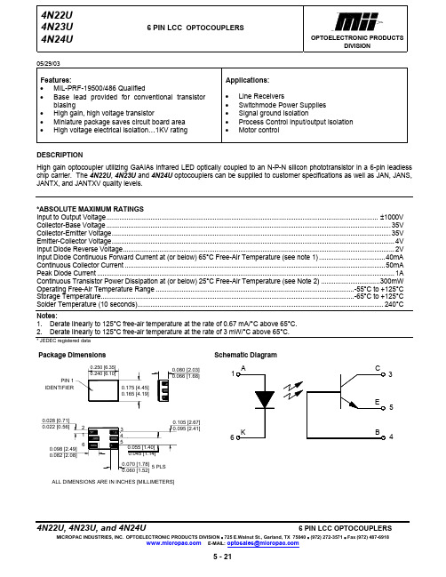
05/29/03Features:• MIL-PRF-19500/486 Qualified• Base lead provided for conventional transistor biasing• High gain, high voltage transistor• Miniature package saves circuit board area• High voltage electrical isolation…1KV rating Applications:• Line Receivers• Switchmode Power Supplies• Signal ground isolation• Process Control input/output isolation • Motor controlDESCRIPTIONHigh gain optocoupler utilizing GaAIAs infrared LED optically coupled to an N-P-N silicon phototransistor in a 6-pin leadless chip carrier. The 4N22U, 4N23U and 4N24U optocouplers can be supplied to customer specifications as well as JAN, JANS, JANTX, and JANTXV quality levels.*ABSOLUTE MAXIMUM RATINGSInput to Output Voltage.................................................................................................................................................... ±1000V Collector-Base Voltage.. (35V)Collector-Emitter Voltage (35V)Emitter-Collector Voltage (4V)Input Diode Reverse Voltage (2V)Input Diode Continuous Forward Current at (or below) 65°C Free-Air Temperature (see note 1)....................................40mA Continuous Collector Current..............................................................................................................................................50mA Peak Diode Current..................................................................................................................................................................1A Continuous Transistor Power Dissipation at (or below) 25°C Free-Air Temperature (see Note 2)................................300mW Operating Free-Air Temperature Range............................................................................................................-55°C to +125°C Storage Temperature..........................................................................................................................................-65°C to +125°C Solder Temperature (10 seconds)......................................................................................................................................240°CMICROPAC INDUSTRIES, INC.OPTOELECTRONIC PRODUCTS DIVISION • 725 E.Walnut St., Garland, TX 75040 • (972) 272-3571 • Fax (972) 487-691805/29/03ELECTRICAL CHARACTERISTICS INPUT LEDT A = 25°C Unless otherwise specifiedPARAMETER SYMBOLMINMAXUNITS TESTCONDITIONS NOTE Input Diode Static Reverse Current I R 100 µA V R= 2VInput Diode Static Forward Voltage -55°C+25°C +100°C V F1.00.80.71.51.31.2V I F = 10mAOUTPUT TRANSISTORT A = 25°C Unless otherwise specifiedPARAMETER SYMBOLMINMAXUNITS TESTCONDITIONS NOTE Collector-Base Breakdown Voltage V(BR)CBO 35 V I C = 100µA, I B= 0, I F = 0Collector-Emitter Breakdown Voltage V(BR)CEO35 V I C = 1mA, I B= 0, I F = 0Emitter-Base Breakdown Voltage V(BR)EBO 4 V I C= 0, I E = 100µA, I F = 0COUPLED CHARACTERISTICST A = 25°C Unless otherwise specifiedPARAMETER SYMBOLMINMAXUNITS TESTCONDITIONS NOTE On State Collector Current 4N22U4N23U 4N24U I C(ON)0.150.20.4mA V CE = 5V, I B = 0, I F = 2mAOn State Collector Current 4N22U4N23U 4N24U I C(ON)2.56.010.0mAV CE = 5V, I B = 0, I F = 10mAOn State Collector Current 4N22U-55°C 4N23U4N24U I C(ON)1.02.54.0mAV CE = 5V, I B = 0, I F = 10mAOn State Collector Current 4N22U+100°C 4N23U4N24U I C(ON)1.02.54.0mAV CE = 5V, I B = 0, I F = 10mAOff State Collector Current +25°C I C(OFF) 100 nA V CE = 20V, I B = 0, I F = 0mA Off State Collector Current +100°C I C(OFF) 100 µA V CE = 20V, I B = 0, I F = 0mACollector-Emitter Saturation Voltage 4N22U4N23U4N24U V CE(SAT)V CE(SAT)V CE(SAT)0.30.30.3VVVI C = 2.5mA, I B = 0, I F = 20mAI C = 5mA, I B = 0, I F = 20mAI C = 10mA, I B = 0, I F = 20mAInput to Output Resistance ALL R I-O1011Ω V IN-OUT= 1kV 1Input to Output Capacitance ALL C I-O 5 pF f = 1MHz, V IN-OUT= 1kV 1Rise Time 4N22U4N23U4N24U t rt rt r151520µsµsµsV CC = 10V, I F = 10mA, R L = 100ΩFall Time 4N22U4N23U4N24U t ft ft f151520µsµsµsV CC = 10V, I F = 10mA, R L = 100ΩNOTE: 1. These parameters are measured between all phototransistor leads shorted together and with both input diode leads shorted together.SELECTION GUIDEPART NUMBER PART DESCRIPTION4N22U Commercial4N23U Commercial4N24U CommercialJAN4N22U JANScreenedJAN4N23U JANScreenedJAN4N24U JANScreenedJANTX4N22U JANTXScreenedJANTX4N23U JANTXScreenedJANTX4N24U JANTXScreenedJANTXV4N22U JANTXVScreenedJANTXV4N23 JANTXVScreenedJANTXV4N24U JANTXVScreenedJANS4N22U JANSScreenedJANS4N23U JANSScreenedJANS4N24U JANSScreenedMICROPAC INDUSTRIES, INC.OPTOELECTRONIC PRODUCTS DIVISION • 725 E.Walnut St., Garland, TX 75040 • (972) 272-3571 • Fax (972) 487-6918。
4N25

I) II)
LTV - 4N26 I) II)
LTV - 4N27 I) II)
I) II) VDE approved
LTV - 4N28
LTV - 4N25 I) II)
LTV - 4N26 I) II)
LTV - 4N27 I) II)
12-29
PHOTOCOUPLER
I) Il
IF VR P VCEO VCBO VECO IC PC Ptot
Rating
80 6 150 30 70 7 100 150 250 2,500 1,500 1,500 500 -55~+100 -55~+150 260
Unit
mA V mW V V V mA mW mW
12-28
Ordering Information
Part Number
LTV-4N25 / 4N25 LTV-4N25M / 4N25M LTV-4N25S / 4N25S LTV-4N25S-TA / 4N25S-TA LTV-4N25S-TA1 / 4N25S-TA1 LTV-4N26 / 4N26 LTV-4N26M / 4N26M LTV-4N26S / 4N26S LTV-4N26S-TA / 4N26S-TA LTV-4N26S-TA1 / 4N26S-TA1 LTV-4N27 / 4N27 LTV-4N27M / 4N27M LTV-4N27S / 4N27S LTV-4N27S-TA / 4N27S-TA LTV-4N27S-TA1 / 4N27S-TA1 LTV-4N28 / 4N28 LTV-4N28M / 4N28M LTV-4N28S / 4N28S LTV-4N28S-TA / 4N28S-TA LTV-4N28S-TA1 / 4N28S-TA1 LTV4N25-V / 4N25-V LTV4N25M-V / 4N25M-V LTV4N25S-V / 4N25S-V LTV4N25STA-V / 4N25STA-V LTV4N25STA1-V / 4N25STA1-V LTV4N26-V / 4N26-V LTV4N26M-V / 4N26M-V LTV4N26S-V / 4N26S-V LTV4N26STA-V / 4N26STA-V LTV4N26STA1-V / 4N26STA1-V LTV4N27-V / 4N27-V LTV4N27M-V / 4N27M-V LTV4N27S-V / 4N27S-V LTV4N27STA-V / 4N27STA-V LTV4N27STA1-V / 4N27STA1-V LTV4N28-V / 4N28-V LTV4N28M-V / 4N28M-V LTV4N28S-V / 4N28S-V LTV4N28STA-V / 4N28STA-V LTV4N28STA1-V / 4N28STA1-V 6-pin 6-pin 6-pin 6-pin 6-pin 6-pin 6-pin 6-pin 6-pin 6-pin 6-pin 6-pin 6-pin 6-pin 6-pin 6-pin 6-pin 6-pin 6-pin 6-pin 6-pin 6-pin 6-pin 6-pin 6-pin 6-pin 6-pin 6-pin 6-pin 6-pin 6-pin 6-pin 6-pin 6-pin 6-pin 6-pin 6-pin 6-pin 6-pin 6-pin
呼吸机专用mos管 AP4N65DY 4A 650V TO-252 TO-251

1DescriptionThe AP4N65D/Y is silicon N-channel EnhancedVDMOSFETs, is obtained by the self-aligned planar Technology which reduce the conduction loss, improve switchingperformance and enhance the avalanche energy. The transistor can be used in various power switching circuit for systemGeneral FeaturesVDS =650V,ID =4A RDS(ON) <2.4Ω@ VGS=10VApplicationUninterruptible Power Supply(UPS) Power Factor Correction (PFC)Package Marking and Ordering InformationC1. Repetitive Rating: Pulse width limited by maximum junction temperature2. I AS = 4A, V DD = 50V, R G = 25 Ω, Starting T J = 25 ºC3. Pulse Test: Pulse width ≤ 300μs, Duty Cycle ≤ 1%23 Typical Characteristics T J = 25ºC, unless otherwise notedFigure 1. Output Characteristics (T J = 25ºC) Figure 2. Body Diode Forward Voltage1.21504 Figure 7. Capacitance Figure 8. Gate ChargeV DS , Drain-to-Source Voltage (V) Q g , Total Gate Charge (nC)Figure 9. Transient Thermal ImpedanceFigure 10. Transient Thermal ImpedanceTO-220F TO-22024681003691215V DD = 120V V DD= 480V V DD= 400V 010203040V GS= 0V f = 1MHzC issC ossC rss10 4102 10 110 010 3Figure A:Gate Charge Test Circuit and WaveformFigure B:Resistive Switching Test Circuit and WaveformFigure C:Unclamped Inductive Switching Test Circuit and Waveform56Package Mechanical DataDimensionsMillimeters Inches Ref.Min.Typ.Max.Min.Typ.Max.A A2B C DE G H LV1V22.1000.660.40 2.500.100.860.600.08300.0260.0160.0980.0040.0340.0246.409.5010.700.3740.4210.0530.0655.906.30L20°6°0.2320.2486.800.2520.2684.47 4.670.1760.1841.09 1.210.0430.0487°1.351.650°6°7°B2 5.18 5.480.2020.216C20.440.580.0170.023D1E15.30REF4.630.1820.209REFDETAIL ATO-252Reel Spectification-TO-252ABBDimensionsMillimeters Inches Ref.Min.Typ.Max.Min.Typ.Max.W E F D0D1P0P1P2A0B0K0T t115.901.657.401.4016.101.857.601.600.6260.0650.2910.0550.6340.0730.2990.0631.40 1.607.9010.4510.600.4110.4170.240.270.0090.0110.0550.0633.90 4.106.900.27110P00.1540.1618.100.3110.3191.90 2.100.0750.0830.100.00440.001.5752.780.10916.001.757.501.501.504.008.002.0010.500.6300.0690.2950.0590.0590.1570.3150.0790.4136.857.002.68 2.880.2700.2760.1050.11339.8040.201.5671.5837Attention1,Any and all APM Microelectronics products described or contained herein do not have specificationsthat can handle applications that require extremely high levels of reliability, such as life support systems,aircraft's control systems, or other applications whose failure can be reasonably expected to result inserious physical and/or material damage. Consult with your APM Microelectronics representative nearestyou before using any APM Microelectronics products described or contained herein in such applications.2,APM Microelectronics assumes no responsibility for equipment failures that result from using productsat values that exceed, even momentarily, rated values (such as maximum ratings, operating conditionranges, or other parameters) listed in products specifications of any and all APM Microelectronicsproducts described or contained herein.3, Specifications of any and all APM Microelectronics products described or contained here instipulate the performance, characteristics, and functions of the describ ed products in the independent state, and arenot guarantees of the performance, characteristics, and functions of the described products as mountedin the customer’s products or equipment. To verify symptoms and states that cannot be evaluated in an independent device, the customer should always evaluate and test devices mounted in the customer’sproducts or equipment.4, APM Microelectronics Semiconductor CO., LTD. strives to supply high quality high reliability products. However, any and all semiconductor products fail with some probability. It is possible that theseprobabilistic failures could give rise to accidents or events that could endanger human lives that couldgive rise to smoke or fire, or that could cause damage to other property. When designing equipment,adopt safety measures so that these kinds of accidents or events cannot occur. Such measures includebut are not limited to protective circuits and error prevention circuits for safe design, redundantdesign,and structural design.5,In the event that any or all APM Microelectronics products(including technical data, services) describedor contained herein are controlled under any of applicable local export control laws and regulations, such products must not be exported without obtaining the export license from the authorities concerned in accordance with the above law.6, No part of this publication may be reproduced or transmitted in any form or by any means,electronic or mechanical, including photocopying and recording, or any information storage or retrieval system, or otherwise, without the prior written permission of APM Microelectronics Semiconductor CO., LTD.7, Information (including circuit diagrams and circuit parameters) herein is for example only; it is notguaranteed for volume production. APM Microelectronics believes information herein is accurate andreliable, but no guarantees are made or implied regarding its use or any infringements of intellectualproperty rights or other rights of third parties.8, Any and all information described or contained herein are subject to change without notice due toproduct/technology improvement,etc. When designing equipment, refer to the "Delivery Specification" forthe APM Microelectronics product that you Intend to use.8。
断路器-C16F4TM125V_DATASHEET

Product data sheetCharacteristicsC16F4TM125V断路器, ComPacT NSX160F, 36 kA, AC, 4P4D,125 A, TMD, VIGI主要信息产品系列ComPacT new generation产品系列ComPacT NSX100...250 new generation 产品类型Circuit breaker with Vigi add-on 产品短名NSX160F 产品应用配电保护极数4P 保护极说明4d 中性线位置左侧网络类型AC 网络频率50/60 Hz额定电流 [In]125 A 在…上 40 °C额定绝缘电压 [Ui]800 V AC 50/60 Hz 符合 EN/IEC 60947-2额定冲击耐受电压 [Uimp]8 KV额定工作电压 [Ue]690 V AC 50/60 Hz 断路器型号F分断能力85 KA Icu 在…上 220/240 V AC 50/60 Hz 符合 EN/IEC 60947-2 36 KA Icu 在…上 380/415 V AC 50/60 Hz 符合 EN/IEC 60947-2 35 KA Icu 在…上 440 V AC 50/60 Hz 符合 EN/IEC 60947-2 30 KA Icu 在…上 500 V AC 50/60 Hz 符合 EN/IEC 60947-2 22 KA Icu 在…上 525 V AC 50/60 Hz 符合 EN/IEC 60947-2 8 KA Icu 在…上 660/690 V AC 50/60 Hz 符合 EN/IEC 60947-2使用分断能力 [Ics]85 KA 在…上 220/240 V AC 50/60 Hz 符合 EN/IEC 60947-2 36 KA 在…上 380/415 V AC 50/60 Hz 符合 EN/IEC 60947-2 35 KA 在…上 440 V AC 50/60 Hz 符合 EN/IEC 60947-2 30 KA 在…上 500 V AC 50/60 Hz 符合 EN/IEC 60947-2 22 KA 在…上 525 V AC 50/60 Hz 符合 EN/IEC 60947-2 8 KA 在…上 660/690 V AC 50/60 Hz 符合 EN/IEC 60947-2隔离功能Yes conforming to EN/IEC 60947-2使用类别AC类脱扣器名称TM-D 脱扣器类型热磁式脱扣器额定值125 A 在…上 40 °C 保护类型过载保护 (长延时) 短路保护 (磁保护)污染等级3 符合 IEC 60664-1T h e i n f o r m a t i o n p r o v i d e d i n t h i s d o c u m e n t a t i o n c o n t a i n s g e n e r a l d e s c r i p t i o n s a n d /o r t e c h n i c a l c h a r a c t e r i s t i c s o f t h e p e r f o r m a n c e o f t h e p r o d u c t s c o n t a i n e d h e r e i n .T h i s d o c u m e n t a t i o n i s n o t i n t e n d e d a s a s u b s t i t u t e f o r a n d i s n o t t o b e u s e d f o r d e t e r m i n i n g s u i t a b i l i t y o r r e l i a b i l i t y o f t h e s e p r o d u c t s f o r s p e c i f i c u s e r a p p l i c a t i o n s .I t i s t h e d u t y o f a n y s u c h u s e r o r i n t e g r a t o r t o p e r f o r m t h e a p p r o p r i a t e a n d c o m p l e t e r i s k a n a l y s i s , e v a l u a t i o n a n d t e s t i n g o f t h e p r o d u c t s w i t h r e s p e c t t o t h e r e l e v a n t s p e c i f i c a p p l i c a t i o n o r u s e t h e r e o f .N e i t h e r S c h n e i d e r E l e c t r i c I n d u s t r i e s S A S n o r a n y o f i t s a f f i l i a t e s o r s u b s i d i a r i e s s h a l l b e r e s p o n s i b l e o r l i a b l e f o r m i s u s e o f t h e i n f o r m a t i o n c o n t a i n e d h e r e i n .控制类型手柄安装类型固定式安装方式底板安装连接方式-上端前连接连接方式-下端前连接机械寿命20000 次电气寿命20000 次 440 V AC 50/60 Hz In/2 符合 IEC 60947-210000 次 440 V AC 50/60 Hz In 符合 IEC 60947-210000 次 690 V AC 50/60 Hz In/2 符合 IEC 60947-25000 次 690 V AC 50/60 Hz In 符合 IEC 60947-2相间距35 Mm接线能力螺钉类型终端 300 mm² 用于EverLink接线的铜或铝本地信号指示合闸位置指示触点位置指示有中性线保护设置Ir长延时电流整定类型可调长延时电流整定值 [Ir]0.7...1 x In长延时时间整定类型固定式[tr] 长延时时间整定范围120…400 S at 1.5 x In15 S at 6 x Ir短延时时间整定类型固定式瞬时保护电流整定类型固定式瞬时保护整定值 [Ii]1250 A漏电流保护漏电保护剩余电流整定类型 5 档可调剩余电流延时整定值 [Δt]0.03…10 A剩余电流延时整定类型可调剩余电流延时时间整定值 [Δt]0 Ms 40 ms60 Ms 140 ms150 Ms 300 ms310 Ms 800 ms过电压类别Class II高度236 Mm宽度140 Mm深度86 Mm产品净重 3.2 Kg环境符合标准EN/IEC 60947产品认证CCCEAC海事IP 保护等级IP40 符合 IEC 60529IK 保护等级IK07 conforming to IEC 62262运行温度-35…70 °C贮存环境温度-50…85 °COffer SustainabilityREACh法规REACh 声明欧盟ROHS指令符合欧盟ROHS声明无汞是RoHS 豁免信息是中国 ROHS 管理办法中国 ROHS 声明保修单18 个月Product Life Status :在售。
Festo VUVB-S-M42-AZD-T516-2AC1 电压阀说明书

01/04/2016 – Reservado el derecho de modificación – Festo AG & Co. KG
2/2
Tipo de control Alimentación del aire de control Sentido del flujo Presión de control Tiempo de conmutación a la desconexión Tiempo de conmutación a la conexión Valores característicos de las bobinas
2,5 kV 3 +/- 10 % Aire comprimido según ISO 8573-1:2010 [7:4:4] Opción de funcionamiento con lubricación (necesaria en otro modo de funcionamiento)
según la normativa UE de baja tensión 1 -20 ... 40 °C -5 ... 50 °C -5 ... 50 °C 2 Nm 150 g Conector según EN 175301-803 Forma C con taladro pasante Placa base sin escape común Placa base QS-5/16
Hoja de datos
Característica Función de las válvulas Tipo de accionamiento Tamaño de las válvulas Caudal nominal normal Presión de funcionamiento Construcción Tipo de reposición Tipo de protección Diámetro nominal Función de escape Principio de hermetización Posición de montaje Accionamiento manual auxiliar
- 1、下载文档前请自行甄别文档内容的完整性,平台不提供额外的编辑、内容补充、找答案等附加服务。
- 2、"仅部分预览"的文档,不可在线预览部分如存在完整性等问题,可反馈申请退款(可完整预览的文档不适用该条件!)。
- 3、如文档侵犯您的权益,请联系客服反馈,我们会尽快为您处理(人工客服工作时间:9:00-18:30)。
6 PIN DIP PHOTOTRANSISTOR PHOTOCOUPLER4N3X Series H11AX SeriesFeatures:• 4N2X series: 4N25, 4N26, 4N27, 4N28 • 4N3X series: 4N35, 4N36, 4N37, 4N38• H11AX series: H11A1, H11A2, H11A3, H11A4, H11A5 • High isolation voltage between input and output (Viso=5000 V rms)• Creepage distance >7.6mm• Operating temperature up to +110°C • Compact dual-in-line package • Pb free and RoHS compliant. • UL approved (No. E214129) • VDE approved (No. 132249) • SEMKO approval pending • NEMKO approval pending • DEMKO approval pending • FIMKO approval pending • CSA approval pendingDescriptionThe 4N2X, 4N3X, H11AX series contains an infrared emitting diode optically coupled to a phototransistor. It is packaged in a 6-pin DIP package and available in wide-lead spacing and SMD option.Applications• Power supply regulators • Digital logic inputs • Microprocessor inputs1. Anode2. Cathode3. No Connection4. Emitter5. Collector6. BaseSchematic6 PIN DIP PHOTOTRANSISTOR PHOTOCOUPLER4N3X Series H11AX SeriesAbsolute Maximum Ratings (T a =25°C)Parameter Symbol Rating Unit Forward currentI F 50 mA Peak forward current (t = 10µs)I FM 1 A Reverse voltageV R 6 V 70 mW InputPower dissipation (T A = 25°C) Derating factor (above 100°C) P D 3.8 mW/°C Collector-Emitter voltage V CEO 80 V Collector-Base voltageV CBO 80 V Emitter-Collector voltage V ECO 7 V OutputEmitter-Base voltageV EBO 7 V 150 mWPower dissipation (T A = 25°C) Derating factor (above 100°C)P C 9.0mW/°CTotal power dissipation P tot 200 mW Isolation voltage *1 V iso 5000 Vrms Operating temperature T opr -55~+110 °C Storage temperature T stg -55~+125 °C Soldering temperature *2 T sol260 °CNotes*1 AC for 1 minute, R.H.= 40 ~ 60% R.H. In this test, pins 1, 2 & 3 are shorted together, and pins 4, 5 & 6 are shorted together. *2 For 10 seconds.6 PIN DIP PHOTOTRANSISTOR PHOTOCOUPLER4N3X Series H11AX SeriesElectrical Characteristics (T a =25°C unless specified otherwise)InputParameter Symbol Min. Typ.* Max. Unit ConditionForward voltage V F - 1.2 1.5 V I F = 10mA Reverse current I R - - 10 µA V R = 6V Input capacitanceC in-30-pFV = 0, f = 1MHzOutputParameter Symbol Min. Typ.* Max. Unit ConditionCollector-Base dark current I CBO - - 20 nA V CB = 10V - - 50V CE = 10V, IF=0mA Collector-Emitter darkcurrentI CEO - - 50nAV CE = 60V, IF=0mACollector-Emitter breakdown voltage BV CEO80 - - V I c =1mACollector-Base breakdown voltage BV CBO 80 -V I C =0.1mAEmitter-Collector breakdown voltage BV ECO 7 - - V I E =0.1mA Emitter-Basebreakdown voltage BV EBO7 - - V I E =0.1mACollector-Emitter capacitanceC CE - 8 - pF VCE=0V, f=1MHz* Typical values at T a = 25°C6 PIN DIP PHOTOTRANSISTOR PHOTOCOUPLER4N3X Series H11AX SeriesTransfer Characteristics (T a =25°C unless specified otherwise)Parameter Symbol Min. Typ.* Max. Unit Condition4N35, 4N36,4N37 100--H11A150 - - H11A5 30 - -4N25, 4N26, 4N38, H11A2, H11A3 20 - - Current transfer ratio4N27, 4N28, H11A4 CTR10--%I F = 10mA, V CE = 10V4N25, 4N26, 4N27, 4N28- - 0.5 I F = 50mA, I c = 2mA4N35, 4N36,4N37 - - 0.3H11A1, H11A2, H11A3, H11A4, H11A5 - - 0.4I F = 10mA, I c = 0.5mACollector-Emitter saturation voltage4N38V CE(sat) - - 1.0VI F = 20mA, I c = 4mA Isolation resistanceR IO 1011 - - ΩV IO = 500VdcInput-output capacitanceC IO- 0.2 - pF V IO = 0, f = 1MHz4N25, 4N26, 4N27, 4N28, H11A1, H11A2, H11A3,H11A4, H11A5- 3 10V CC = 10V, I F = 10mA,R L = 100Ω See Fig. 11Turn-on time4N35, 4N36, 4N37, 4N38 Ton- 10 12µsV CC = 10V, I C = 2mA,R L = 100Ω, See Fig. 114N25, 4N26, 4N27, 4N28, H11A1, H11A2, H11A3, H11A4- 3 10V CC = 10V, I F = 10mA, R L = 100Ω See Fig. 11Turn-off time4N35, 4N36, 4N37, 4N38Toff- 9 12µsV CC = 10V, I C = 2mA, R L = 100Ω, See Fig. 11* Typical values at T a = 25°C6 PIN DIP PHOTOTRANSISTOR PHOTOCOUPLER4N3X SeriesH11AX SeriesTypical Performance Curves6 PIN DIP PHOTOTRANSISTOR PHOTOCOUPLER4N3X SeriesH11AX SeriesFigure 11. Switching Time Test Circuit & WaveformsI FI CR LR INR BEV CCOutputInputInput PulseOutput Pulse10%90%t f t r t offt on6 PIN DIP PHOTOTRANSISTOR PHOTOCOUPLER4N3X Series H11AX SeriesOrder InformationPart Number4NXXY(Z)-VorH11AXY(Z)-VNoteXX = Part no. for 4NXX series (25, 26, 27, 28, 35, 36, 37 or 38) X = Part no. for H11AX series (1, 2, 3, 4, or 5) Y = Lead form option (S, S1, M or none) Z = Tape and reel option (TA, TB or none). V = VDE (optional)Option Description Packing quantityNone Standard DIP-665 units per tube M Wide lead bend (0.4 inch spacing)65 units per tube S (TA) Surface mount lead form + TA tape & reel option 1000 units per reel S (TB) Surface mount lead form + TB tape & reel option1000 units per reel S1 (TA) Surface mount lead form (low profile) + TA tape & reel option 1000 units per reel S1 (TB)Surface mount lead form (low profile) + TB tape & reel option1000 units per reel6 PIN DIP PHOTOTRANSISTOR PHOTOCOUPLER4N3X Series H11AX SeriesPackage Drawings(Dimensions in mm)Standard DIP TypeOption M Type6 PIN DIP PHOTOTRANSISTOR PHOTOCOUPLER4N3X Series H11AX SeriesOption S TypeOption S1 Type6 PIN DIP PHOTOTRANSISTOR PHOTOCOUPLER4N3X Series H11AX SeriesDevice MarkingNotesEL denotes Everlight4N35 denotes Device Number Y denotes 1 digit Year code WW denotes 2 digit Week code V denotes VDE (optional)EL 4N35YWWV6 PIN DIP PHOTOTRANSISTOR PHOTOCOUPLER4N3X Series H11AX SeriesTape dimensionsDimension No.A B Do D1 E F Dimension (mm) 10.4±0.1 7.52±0.1 1.5±0.1 1.5+0.1/-0 1.75±0.1 7.5±0.1Dimension No.Po P1 P2 t W K Dimension (mm) 4.0±0.15 16.0±0.1 2.0±0.1 0.35±0.03 16.0±0.2 4.5±0.1Option TAOption TBDirection of feed from reel Direction of feed from reel6 PIN DIP PHOTOTRANSISTOR PHOTOCOUPLER4N3X Series H11AX SeriesSolder Reflow Temperature Profile6 PIN DIP PHOTOTRANSISTOR PHOTOCOUPLER4N3X Series H11AX SeriesDISCLAIMER1. Above specification may be changed without notice. EVERLIGHT will reserve authority on material changefor above specification.2. When using this product, please observe the absolute maximum ratings and the instructions for use asoutlined in these specification sheets. EVERLIGHT assumes no responsibility for any damage resulting from use of the product which does not comply with the absolute maximum ratings and the instructions included in these specification sheets.3. These specification sheets include materials protected under copyright of EVERLIGHT Corporation.Please do not reproduce or cause anyone to reproduce them without EVERLIGHT’s consent.。
