cs161-04
35kV变电站工程SDH设备

块
0
1.3.11
STM-16板卡(含模块)
块
0
1.3.12
STM-64板卡(含模块)
块
0
….
………
1.4
业务板卡
1.4.1
10/100M自适应以太网板卡(含出线板卡)
SED/ EIFEx6电口,交换型
块
2
1.4.2
千兆以太网板卡(含出线板卡)
块
0
1.4.3
E1板卡(含出线板卡)
块
4(一块用于帕拉菲变,3块用于台乡变)
1.3.3
STM-16母板
块
0
1.3.4
STM-64母板
块
0
1.3.5
STM-1光接口模块
块
0
1.3.6
STM-4光接口模块
L4.1光模块
块
8
1.3.7
STM-16光接口模块
块
0
1.3.8
STM-64光接口模块
块
0
1.3.9
STM-1板卡(含模块)
块
0
1.3.10
块
0
5.14
光接口模块
块
0
5.15
E1板卡
块
0
5.16
机柜
面
0
5.17
架顶电源
套
0
5.18
配套线缆及安装工具
套
0
…
……
6
配线设备
6.1
光纤配线柜
台
0
6.1.1
机柜
台
0
6.1.2
光纤配线单元
个
0
6.1.3
Valtek MaxFlo 4 Eccentric Rotary Plug Control Valv

Valtek MaxFlo 4 Eccentric Rotary Plug Control ValveMaxFlo 4 Eccentric Rotary Plug Control Valve2The Flowserve Valtek MaxFlo 4 control valve is a high performance eccentric rotary plug valve designed for the process industry. It features a large capacity, standard hardened trim and superior shaft blow-out protection. This valve is available in sizes 1 through 12 inches, ASME Class 150, 300 and 600 as well as DIN PN 10, PN16, PN 25, PN40 and PN63.An optional ISA 75.08.01 or DIN EN 558 series 1 long-pattern body makes this valve an easy drop-in replacement for a globe control valve.The MaxFlo 4 is suitable for most applications; its control valve features include:• Highest Rated Cv • Precise Control • Reliable Shut-off• Most Current Safety Standards • Fugitive Emissions Elimination •Integral Noise Reduction PlatesHighest Rated CvThe unique design of the MaxFlo 4 shaft and plug provide as much as 70% more Cvcompared to the competition. This allows customers to get more flow when neededand sometimes allows for a smaller, more economical valve to be used.Precise ControlThe MaxFlo 4 polygon connection between the shaft and plug is a proven superiormethod for making demanding mechanical connections that are stronger, more preciseand have a substantially longer service life. This reduces backlash and the high strengthof the polygon connections makes them capable of withstanding greater shock loadsunder extreme torque reversal conditions.Reliable Shut-offThe MaxFlo 4 double-offset eccentric plug rotates into the seat at an angle that eliminatessliding over the seat surface. This design reduces seat wear, and thereby decreases main-tenance requirements and costs. At the same time, a tight ANSI Class VI shutoff is easilyobtainable using the soft seat design.Safety StandardThe shaft is designed to meet the safety requirements of industry standard ASME B16.34to ensure that the shaft is retained even if the actuator is removed when the valve is stillpressurized. This is standard on every MaxFlo 4 to provide our customers with confidenceand safety.3Separate bonnet ensures positive anti-blowout, accommodates multiple packing options, and offers flexibility in material selection for demandingapplications.Heavy-duty rigid metal seat,with hardfaced or soft-seat options, provides tighter shutoff, and easier maintenance. Available in full area and several reductions in every size to suit your process needs.Blow out proof shaft required by ASME B16.34 2004 Sec 6.5 ensures safety. Standard on every MaxFlo 4.An economical flangeless configuration of the MaxFlo 4 is also available. The standard flanged body is the same length. To replace existing globe valves we offer the flanged body with the same face to face length as a globe valve (Per ISA 75.08.01).4Open Flow Path gives as much as 70%more C v than competitive valves that have the shaft obstructing the flow. In many cases it is possible to use a smaller, more economical MaxFlo 4.Flanged end post allows for easy maintenance.Hard stainless steel plug requires no breakout torque and increases valve life as the plug lifts off the seat immediately when it begins rotating.Precision NC machined plug and shaft significantly reduces maintenance costs byallowing replacement of only the necessary parts.Polygon shaft/plug connection for precise robust control.Shimless seat offers simplified assembly and easy maintenance.5Eliminate Fugitive EmissionsSpecial Flowserve packing sets, such as SureGuard XT live loaded packing, are available to control fugitive emissions. Packing options include: PTFE V-Ring, Braided PTFE, Graphite, Sureguard XT, Garlock SVS, LATTYflon 3265 LM and LATTYgraf 6995 NG (meeting requirements for TA-Luft, ISO 15848-1 class B and A, and EPA standards).Integral Noise-Reduction Plate OptionDesigned to reduce noise levels by 5 to 10 dBA, our integral plate fits into the valve body. It can be easily maintained using the same tools required for the seat retainer. It is perfectly suitable with all gases in the shaft-downstream direction, and the plate does not change the length of the valve.Integrated Control Valve SolutionOperated by a diaphragm, piston, or rack-and-pinion actuator coupled with a Logix digital positioner, the MaxFlo 4 maintains high positioning accuracy, repeatability, controlled high speed and reliable response. With the advanced diagnostic solutions that can be seamlessly integrated into a host control and/or plant asset management system, along with state-of-the-art features and performance, the MaxFlo 4 is the most economical Eccentric Rotary Plug valve in the market.NR Diaphragm Rotary ActuatorThe Flowserve NR diaphragm rotary actuator is a rugged single-acting actuator designed to provide high performance, long life and reliability. The diaphragm actuator is very sensitive to small changes in air supply, which allows it toprecisely move the valve plug without over shoot.6Logix 3000MD+ Digital PositionerEasiest calibration and configuration of any positioner available. Single, push-button calibration and DIP switch configuration allow you to fully commission the positioner in a matter of minutes. Using ValveSight Software DTM brings the availability of 24/7 diagnostics.For more information see document number LGENIM0059 and LGENIM3404 at .Logix 500MD+ Series Digital PositionerTo minimize your total cost of ownership and maximize productivity, Flowserve developed the Logix MD+ digital positioner. The Logix MD+ digital positioner allows for fast, simple commis-sioning, extremely accurate and reliable control, and diagnostic features that provide powerfuland easy ways to determine when maintenance is required.ValveSight™ Diagnostic Software – Prevention deliveredValveSight is a diagnostic solution for control valves that can be seamlessly integrated into a host control and/or plant asset management system. The power of ValveSight is the intel-ligent diagnostic engine -- which detects an emerging condition in the valve, actuator, posi-tioner, and control signal -- that may indicate a performance, safety, or environmental problem. ValveSight advises which corrective actions totake to prevent a failure.VR Spring Cylinder Rotary ActuatorThe Flowserve VR spring cylinder rotary actuator combines high torque and pneu-matic stiffness with excellent throttling capabilities. These characteristics are designed into a lightweight, rugged and compact assembly, making the Flowserve spring cylinder rotary actuator an excel-lent choice for quarter-turn applications.SuperNova Rack & Pinion Rotary ActuatorThe Flowserve SuperNova rack & pinion rotary actuator is designed forreliability, versatility and safety. Rugged, yet compact construction combined with technical solutions make this product extremely reliable in the severest of operating conditionsLogix 420 Digital PositionerThe Logix 420 is the latest addition to the digital positioner family from Flowserve. When mounted to the MaxFlo 4 eccentric rotary plugcontrol valve, Logix 420 provides the user with a cost competitive solutionfor the general service, explosion proof market. For more information see document numberLGENIM0106 at www .Unparalleled Service: Day or Night, WorldwideFlowserve Quick Response Centers (QRCs) are equipped with thousands of parts, including OEM andFlowserve custom-built products. Each has the manpower andequipment to expedite time-sensitiverepairs of any size.7To find your local Flowserve representative:For more information about Flowserve Corporation, visit or callUSA 1 800 225 6989 or International +1 972 910 0774FCD VLENBR0064-01-AQ Printed in USA. November 2015. © 2015 Flowserve Corporation United States Flowserve1350 N. Mt. Springs Parkway Springville, UT 84663USAPhone: +1 801 489 8611Fax: +1 801 489 3719AustriaFlowserve Control Valves GmbH Kasernengasse 69500 Villach AustriaPhone: +43 (0)4242 41181 0Fax: +43 (0)4242 41181 50FranceFlowserve France S.A.S.BP 60 63307 Thiers Cedex FrancePhone: 33 4738 04266Fax: 33 4738 01424IndiaFlowserve India Controls Pvt. Ltd Plot # 4, 1A, E.P .I.P , Whitefield Bangalore Kamataka India 560 066Phone: +91 80 284 10 289Fax: +91 80 284 10 286SingaporeFlowserve Pte. Ltd.12 Tuas Avenue 20Republic of Singapore 638824SingaporePhone: +65 6879 8900Fax: +65 6862 4940Saudi ArabiaFlowserve Abahsain Flow Control Co., Ltd.Makkah Road, Phase 4Plot 10 & 12, 2nd Industrial City Damman, Kingdom of Saudi ArabiaPhone: +966 3 857 3150 ext. 243Fax: +966 3 857 4243ChinaFlowserve Fluid Motion and Control (Suzhou) Co., Ltd.No. 35, Baiyu RoadSuzhou Industrial Park, Suzhou Jiangsu Province, P .R. 215021ChinaPhone: 86 512 6288 8790Fax: 86 512 6288 8736。
CSC-161 系列数字式线路保护装置说明书

1.1 CSC-160 系列保护装置适用范围........................................................................... 1 1.2 CSC-160 系列保护装置主要特点........................................................................... 3 1.3 装置外形尺寸和安装尺寸...................................................................................... 4 1.4 装置外观.................................................................................................................. 5 1.5 装置执行的标准...................................................................................................... 5 1.6 CSC-161 系列装置的适用范围............................................................................... 5 1.7 本说明书适用范围.................................................................................................. 5
SAP常用T-Code汇总情况
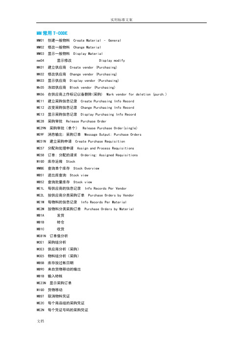
MM常用T-CODEMM01 创建一般物料Create Material – GeneralMM02 修改一般物料Change MaterialMM03 显示一般物料Display Materialmm04 显示修改 Display modifyMK01 建立供应商Create vendor (Purchasing)MK02 修改供应商Change vendor (Purchasing)MK03 显示供应商Display vendor (Purchasing)Mk05 冻结供应商Block vendor (Purchasing)MK06 在供应商上作标记以备删除(采购) Mark vendor for deletion (purch.) ME11 建立采购信息记录Create Purchasing Info RecordME12 改变采购信息记录Change Purchasing Info RecordME13 显示采购信息记录Display Purchasing Info RecordME28 采购审批Release Purchase OrderME29N 采购审批(单个)Release Purchase Order(single)ME9F 消息输出: 采购订单Message Output: Purchase OrdersME51N 建立采购申请Create Purchase RequisitionME57 分配和处理申请Assign and Process RequisitionsME58 订单: 分配的请求Ordering: Assigned RequisitionsMIGO 库存运做StockMMBE 查询单个库存Stock OverviewMB51 进出库查询Stock viewMB52 查询批量库存Stock viewME1L 每供应商的信息记录Info Records Per VendorME2L 按供应商分类采购订单Purchase Orders by VendorME1M 每物料的信息记录Info Records Per MaterialME2M 按物料分类采购订单Purchase Orders by MaterialMB1A 发货MB1B 转仓MB1C 收货ME81N 订单值分析MCE1 采购组分析MCE3 供应商分析(采购)MCE5 物料组分析(采购)MB5B 库存按过帐日期MB90 来自货物移动的输出MB1B 输入转帐ME23N 显示采购订单MIGO 货物移动MBST 取消物料凭证ME2C 每个商品组的采购凭证ME2N 每个凭证号码的采购凭证MI01 创建实地盘存凭证MI02 改变实物盘存凭证MI03 显示实地盘点凭证MI04 输入库存计数MI05 改变库存计数MI06 显示库存计数MI07 库存差额总览计数MI09 输入无参考凭证计数MI20 库存差额清单MI21 打印库存盘点凭证MI22 显示物料的实际盘点凭证MI23 显示商品的库存盘点数据MI24 库存盘点清单MB54 显示供应商寄售库存MCBA 工厂分析MCBC 库存地分析MCBE 物料分析MCBR 批次分析MC.1 工厂分析:库存MC.2 工厂分析:收货/发货MB21 创建预留MB22 修改预留MB23 显示预留MB25 预留清单MBVR 管理预留与BOM相关CS00 BOM 菜单BOM MenuCS01 生成物料 BOM Create Material BOMCS02 更改物料 BOM Change MaterialCS03 显示物料 BOM Display Material BOMCS11 逐层显示 BOM Display BOM Level by LevelCS12 多层 BOM Multi-level BOMCS13 汇总 BOM Summarized BOMCS14 BOM 比较BOM ComparisonCS15 单层反查清单Single-Level Where-Used ListCS20 大量更改 : 初始屏幕Mass Change: Initial ScreenCS80 显示修改CSMB 物料BOM层次列印BOMCA21 生成定额工艺路线Create rate routingC223 创建生产版本Create Product verKKF6N 处理产品成本收集器Create Production Cost Collector与生产计划相关MDBT 后台定时运算MD01 前台运算MD02 MRP 运算单项, 多级MRP - Single-item, Multi-levelMD04 显示库存/需求状况Display Stock/Requirements Situation MF60 拉料单Pull listMF50 改变运行计划数量Change Run Schedule QuantitiesMD11 建立计划订单Create Planned OrderMD12 修改计划订单Change Planned OrderMD13 显示计划订单Display Planned OrderMMBE 库存总览Stock OverviewMFBF 反冲Backflush - Repetitive ManufaturingMF47 未清的再处理记录/每行Open Reprocessing Records / Pr.Line MD61 建立计划独立需求Create Planned Indep. RequirementsMD62 修改计划独立需求Change Planned Indep. RequirementsMD63 显示计划独立需求Display Planned Indep. Requirements与序列号相关IQ01 单个创建序列号Create material serial numberIQ02 修改物料系列号Change material serial numberIQ03 显示物料系列号Display material serial numberIQ04 批量创建物料系列号Create material serial numberIQ08 批量修改物料系列号Change material serial numberIQ09 批量显示物料系列号Display material serial numberSD常用T-CODE与客户相关VD01 建立客户Create customerVD02 更改客户Change customerVD03 显示客户Display customerVK11 创建条件Create ConditionVK12 修改条件Change ConditionVK13 显示条件Display ConditionVA21 创建报价Create QuotationVA22 更改报价Change QuotationVA23 显示报价Display QuotationVA01 创建销售订单Create Sales OrderVA02 修改销售订单Change Sales OrderVA03 显示销售订单Display Sales OrderVA05 销售订单清单List of Sales Orders发货单维护和查询VL01N 创建交货Create DeliveryVL02N 更改交货Change DeliveryVL03N 显示交货Display DeliveryVL06O 查询销售订单Query Sales OrderVLSP 拆分销售单Split Sales OrderVL22 拆分发货单Split DeliveryVL09 取消发货过账Cancel Goods Issue for Delivery Note VL10D STO发货单创建Extended Mult. Processing Deliveries VKM5 对因信用控制冻结的发货单解冻Block Delivery运单维护VT01N 创建发运Create shipmentVT02N 更改发运Change shipmentVT03N 显示发运Display shipmentMB5T 显示在途库存Stock view发票创建VF01 创建出具发票凭证Create Billing DocumentVF02 更改出具发票凭证Change Billing DocumentVF03 显示出具发票凭证Display Billing DocumentVF04 处理出具发票到期清单Process Billing Due ListVF11 取消出具发票凭证Cancel Billing DocumentSAP中的移动类型SAP系统中用于标志物料移动(收货/发货/转储/转储记帐)的三位的数字/字母通常分几大类:收货发货转储库房调整常用的有:收货类 (MB1C)101 采购订单收货 103 采购订单收货至冻结状态 122 无采购订单退货 161 按退货采购订单退货 131 从生产订单501 无采购订单收货 511 免费收货发货类(MB1A)201 成本中心消耗 261 内部订单消耗541 委外加工发货551 库房报损转储类(MB1B)301 工厂间转储(一步) 311 存储地点间转储 309 编码转换 321-325 库存类为冻结/质检状态的记帐修改移动调整类盘赢盘亏一般控制比较严通常我们说的移动类型是IM(库存管理)移动类型移动类型在重复制造模式企业的应用1/库房收货处唯一任务是收货按采购订单号码清点货物数量整理通知IQC准备质检101 按采购订单收货 MB01 没上WM会收到PO指定的存储地点有WM会收到收货区(是对应WM移动类型决定)使用QM模块并在主数据中设定必须做IQC的物料收货后自动转为质检库存类直到作出使用决定后再移动501 无采购订单收货511 免费收货 MIGO/MB1C2/库房材料库主要任务是WM转储/库存调拨/按生产订单投料/非生产消耗/盘库WM转库就不讲了库存调拨有工厂间调拨 301 存储地点间调拨 311 事务码都是MB1A还分一步和两步方法例如用 303+305 效果与301类似但两个工厂都需要做动作用内部订单控制月底结算双方对帐对特殊库存状态(special storage category)物料库存调拨需要用特殊移动类型质检料的转库 323 冻结料的转库 325对库存状态变化质检->自由库存 321 MB1B编码转换 309 MB1B由于生产方式是重复制造采用反冲方法将原材料转入supply area 通过生产线软件取数据自动confirm 生产订单然后反冲先根据order消耗然后发货到生产线收货区对材料 261消耗到订单对应前端MB1C 对半成品/成品 101收货对应前端MB31报损 551 MB1C 这里的移动原因一般是强制输入的以便月底报表区分各部门数据(供应商原因/研发原因/各生产线原因)借料系统里面没有拷一个出来就是自然是借到成本中心来控制月底盘库 701/702 Or 711/712 这个用户看不到对盘库差异清算自动产生3/库房发货处这里的移动类型也看不见对这里人员是根据delivery note和shipping noification发货601 销售出库633 寄售出库(总部->分公司)541 委外加工发货▲什么是Movement type ?1.物料的移动在SAP中的反映,也可以理解为物流业务在SAP中的反映2.移动类型可以根据物料类型的Quantity/Value属性,更新(数量(Stock)或价值(FI凭证/科目的确定)3.移动类型的字段显示(Screen)可以在IMG中设置4.MRP,ATP check 等计算的基础5.链接SAP各模块▲Movement typeMvt type Description1xx GR from Pur/Prd and return2xx GI for Consumption3xx,4xx Transfer5xx GR W/O ref to Pur/Prd Order6xx LE-SHP movement types7xx Physical inventory(IM:70x/WM:71x)8xx BrazilCustomer 9xx,Xxx,Yxx,Zxx▲T-Code: OMJJMenu path: IMG - Materials Management - Inventory Management and Physical Inventory – Movement type - Copy, ChangeMovement TypesGI: goods issue (consumption/usage, withdrawal) or goods receipt without reference;发料GR: goods receipt with reference to a purchase order or production orderGD: goods movement with reference to a delivery (from the Shipping component)RE: return delivery, return, reversalRE: returns reversalTP: transfer to company's own stockTF: transfer postingTR: reversal of transfer postingSLS: sales value receipt▲Movement type tablesCustomized tableT156 Movement Type - BWARTT156B Movement Types: Screen Selection (BWART+SOBKZ)Batch determinationT156SC Mvt Type: Qty/Value Posting: Customer Table; as of Rel. 4.6A ;QM.Inspection T156Q Movement Type: Material-Independent ControlT156X Trans./Event Key ModificationT156T Movement Type TextT158B Check Table: Movement Type for Transaction CodeT157H Help Texts for Movement TypesT157D Reason for MovementT156N Next Movement TypeTMCA Evaluating movement types for LIS updateSystem tableT156SY Mvt Type: Qty/Value Update: System Table; Rel. 4.6A;(SAP 快捷键F1 帮助F3 返回F4 选择输入项F5 新增F6 复制为。
CSC-161 系列数字式线路保护装置说明书

若有特殊定制,请以工程说明书、工程资料为准。 3) 为防止装置损坏,严禁带电插拔装置各插件、触摸印制电路板上的
芯片和器件。 4) 请使用合格的测试仪器和设备对装置进行试验和检测。 5) 装置如出现异常或需维修,请及时与本公司服务热线联系。 6) 本装置的出厂权限密码是:8888。
目录
第一篇 装置的技术说明 .................................................. 1
2 技术条件 ............................................................ 6
2.1 环境条件.................................................................................................................. 6 2.2 电气绝缘性能.......................................................................................................... 6 2.3 机械性能.................................................................................................................. 6 2.4 电磁兼容性.............................................................................................................. 7 2.5 安全性能.................................................................................................................. 7 2.6 热性能(过载能力).............................................................................................. 7 2.7 功率消耗.................................................................................................................. 7 2.8 输出触点容量.......................................................................................................... 7 2.9 装置主要技术参数.................................................................................................. 8 2.10 运输和贮存............................................................................................................ 9
横河资料 功能块

CS 1000/CS 3000ReferenceFunction Block Details 功能块详细说明CONTENTS 目录PART-C Function Block Common C部分功能块C1. Structure of a Function Block ..................................................C1-1 功能块的构成C2. I/O Connection ..........................................................................C2-1 输入输出连接C2.1 Data Connection ........................................................................................... C2-3 数据连接C2.2 Terminal Connection................................................................................... C2-13 未端连接C2.2.1 Connection between Function Blocks ........................................... C2-14 功能块之间的连接C2.2.2 Connection by a Switch Block (SW-33, SW-91) ............................ C2-16 开关模块的连接C2.3 Sequence Connection ................................................................................ C2-19 序列连接C2.4 Connection between Control Stations....................................................... C2-22 控制点的连接C2.5 I/O Connection Information ........................................................................ C2-25 输入输出连接信息C3. Input Processing ......................................................................C3-1 输入处理C3.1 Input Signal Conversion ............................................................................... C3-5 输入信号的变换(转换)C3.1.1 Input Signal Conversions Common to Regulatory Control Blocksand Calculation Blocks ................................................................... C3-7 一般的输入信号到普通控制块和计算快C3.1.2 Input Signal Conversion for Logic Operation Blocks ...................... C3-19 输入信号连接逻辑运算快C3.2 Digital Filter ................................................................................................. C3-20 数字滤波C3.3 Integration ................................................................................................... C3-23 整合C3.4 PV/FV/CPV Overshoot ................................................................................ C3-26 Pv/fv/cpv 溢出C3.5 Calibration ................................................................................................... C3-28校准C3.6 Input Proce ssing in the Unsteady State .................................................... C3-30 动态的输入处理(操作)C3.6.1 Input Processing of the Regulatory Control Block inUnsteady State ........................................ C3-32普通控制块的动态的输入处理C3.6.2 Input Processing of the Calculation Block in Unsteady State ......... C3-34 动态的计算块输入处理C3.7 Input Proce ssing for Sequence Connection ............................................. C3-38 顺序快的输入处理C4. Output Processing....................................................................C4-1 输出处理(操作)C4.1 Output Limiter ............................................................................................... C4-8 输出限制C4.2 Output Velocity Limiter ............................................................................... C4-11 输出变化限制C4.3 Output Clamp .............................................................................................. C4-12 输出固定C4.4 Pre set Manipulated Output......................................................................... C4-19 预设操作输出C4.5 Output Tracking .......................................................................................... C4-21 输出跟踪C4.6 Output Range Tracking ............................................................................... C4-25 输出范围跟踪C4.7 Manipulated Output Index .......................................................................... C4-28 操作输出指示C4.8 Output Signal Conversion .......................................................................... C4-29 输出信号转换C4.8.1 No-Conversion ............................................................................. C4-32C4.8.2 Pulse Width Output Conversion .................................................... C4-36 脉冲输出转换C4.8.3 Communication Output Conversion .............................................. C4-42 通讯输出的转换C4.8.4 Output Signal Conversion of Logic Operation Blocks .................... C4-43 输出信号转换到逻辑运算块C4.9 Auxiliary Output .......................................................................................... C4-44 辅助输出C4.10 Output Proce ssing in Unsteady State ....................................................... C4-48 动态的辅助输出C4.11 CPV Pushback ............................................................................................ C4-49 运算输出协议C4.12 Output Proce ssing in Sequence Connection ............................................ C4-52 顺序连接的输出处理C5. Alarm Processing – FCS .........................................................C5-1报警处理C5.1 Input Open Alarm Check .............................................................................. C5-6 输入开路报警检查C5.2 Input Error Alarm Check ............................................................................... C5-8 输入误差报警检查C5.3 Input High-High and Low-Low Limit Alarm Check .................................... C5-10 输入高高限或者低低限报警检查C5.4 Input High and Low Limit Alarm Check ..................................................... C5-13 输入高限或者低限报警检查C5.5 Input Velocity Alarm Check ........................................................................ C5-16 输入点报警检查C5.6 Deviation Alarm Check ............................................................................... C5-19 偏差报警检查C5.7 Output Open Alarm Check ......................................................................... C5-24 输出开路报警检查C5.8 Output Fail Alarm Check ............................................................................ C5-26 输出故障报警检查C5.9 Output High and Low Limit Alarm Check .................................................. C5-27 输出高限或者低限报警检查C5.10 Bad Connection Status Alarm Check ........................................................ C5-29 C5.11 Proce ss Alarm Message ............................................................................. C5-30 过程报警报告C5.12 System Alarm Message 系统报警报告................................................. C5-31C5.13 Deactivate Alarm Detection 取消的报警监测............................................C5-32C5.14 Alarm Inhibition (Alarm OFF) 禁止的报警.................................... C5-33C5.15 Classification of Alarm Actions Based on Alarm Priority ......................... C5-35 分类的报警优先权限C5.15.1 Alarm Display Flashing Actions 报警显示闪光动作.................. C5-36C5.15.2 Repeated Warning Alarm 重复报警................................................ C5-38 C5.16 Alarm Processing Levels 报警处理的色彩级别 ................................... C5-39 C6. Block Mode and Status 模块的模式和状态....................C6-1 C6.1 Block Mode 块模式.................................................................. C6-2 C6.1.1 Basic Block Mode 基本块模式............................................... C6-3C6.1.2 Compound Block Mode 复合块模式....................................... C6-5C6.1.3 Block Mode Transition模块变换...................................... C6-13C6.1.4 Block Mode Change Command模块更改命令. ............................ C6-20C6.1.5 Block Mode Transition Condition模块转型的条件 ........... C6-21C6.2 Block Status................................................................................ C6-27C6.3 Alarm Status ................................................................................................ C6-28C6.4 Data Status .................................................................................................. C6-32C7. Process Timing ........................................................................ C7-1C7.1 Process Timing for Regulatory Control Block ............................................ C7-3 C7.1.1 Scan Period .................................................................................... C7-4C7.1.2 Order of Process Execution ............................................................ C7-7C7.1.3 Timing of Process I/O ................................................................... C7-11C7.1.4 Control Period for Controller Block ................................................ C7-26C7.2 Process Timing of Calculation Block......................................................... C7-30C7.3 Process Timing for Sequence Control Block ............................................ C7-35 C7.3.1 Execution Timing for Sequence Control Blocks ............................. C7-36C7.3.2 Output Timing of Sequence Table Blocks (ST16, ST16E).............. C7-40C7.3.3 Output Timing of a LC64 Logic Chart Block ................................... C7-41C7.3.4 Combination of Execution Timing and Output Timing .................... C7-42C7.3.5 Control Period and Control Phase for Sequence Table Blocks(ST16, ST16E).............................................................................. C7-43C7.3.6 Control Period and Control Phase for Logic Chart Block (LC64) .... C7-45C1. Structure of a Function Block 功能块结构A function block consists of the following components:一个功能块包括以下部分• Input and output terminals that exchange data with devices outside of the external function block输入和输出终端,与外部设备交换数据的外部功能块• Four processing functions of input processing, calculation processing, output processing, and alarm processing四个处理功能的输入处理,计算处理,输出处理,并报警处理• Constants and variable data used to execute processing functions. Especially,an abbreviated name called “data item” is assigned to data that is referenced orset during the operation.常量和变量用来执行数据处理功能。
AXIS M4216-LV 四分辨率变焦不动瞭望头摄像头
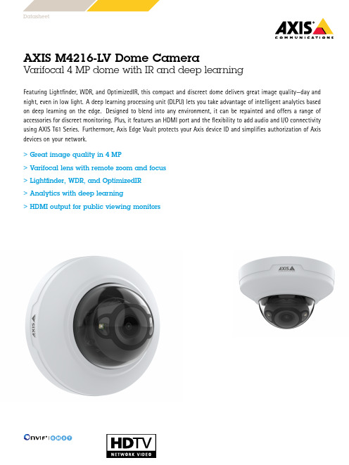
DatasheetAXIS M4216-LV Dome CameraVarifocal4MP dome with IR and deep learningFeaturing Lightfinder,WDR,and OptimizedIR,this compact and discreet dome delivers great image quality—day and night,even in low light.A deep learning processing unit(DLPU)lets you take advantage of intelligent analytics based on deep learning on the edge.Designed to blend into any environment,it can be repainted and offers a range of accessories for discreet monitoring.Plus,it features an HDMI port and the flexibility to add audio and I/O connectivity using AXIS T61Series.Furthermore,Axis Edge Vault protects your Axis device ID and simplifies authorization of Axis devices on your network.>Great image quality in4MP>Varifocal lens with remote zoom and focus>Lightfinder,WDR,and OptimizedIR>Analytics with deep learning>HDMI output for public viewing monitorsAXIS M4216-LV Dome Camera CameraImage sensor1/2.7”progressive scan RGB CMOSLens Varifocal,3–6mm,F1.9-2.7Horizontal field of view:100°–45°Vertical field of view:72°–34°Remote focus and zoom,fixed irisDay and night Automatic IR-cut filterMinimum illumination With Lightfinder:Color:0.18lux at50IRE F2.0B/W:0.03lux at50IRE F2.0,0lux when IR illumination is onShutter speed1/37500s to1/5sCamera angle adjustment Pan±180°,tilt-40to+65°,rotation±105°Can be directed in any direction and see the wall/ceilingSystem on chip(SoC)Model CV25Memory1024MB RAM,512MB Flash ComputecapabilitiesDeep learning processing unit(DLPU) VideoVideo compression H.264(MPEG-4Part10/AVC)Main and High Profiles H.265(MPEG-H Part2/HEVC)Main and High Profiles Motion JPEGResolution2304x1728to320x240Frame rate Up to25/30fps with power line frequency50/60Hz in H.264and H.265aVideo streaming Multiple,individually configurable streams in H.264,H.265and Motion JPEGAxis Zipstream technology in H.264and H.265Controllable frame rate and bandwidthVBR/MBR H.264/H.265Low latency modeHDMIMulti-viewstreamingUp to2individually cropped out view areas in full frame rateHDMI output HDMI1080p(16:9)@25/30fps(50/60Hz)HDMI720p(16:9)@50/60fps(50/60Hz)Image settings Compression,color,brightness,sharpness,contrast,whitebalance,exposure control,motion-adaptive exposure,WDR:upto110dB depending on scene,text and image overlay,mirroringof images,privacy maskRotation:0°,90°,180°,270°,including Corridor FormatPan/Tilt/Zoom Digital PTZAudioAudio input/output Audio features through portcast technology:two-way audio connectivity,voice enhancerNetworkNetwork protocols IPv4,IPv6USGv6,ICMPv4/ICMPv6,HTTP,HTTPS,TLS,QoS Layer 3DiffServ,FTP,SFTP,CIFS/SMB,SMTP,mDNS(Bonjour),UPnP®, SNMP v1/v2c/v3(MIB-II),DNS/DNSv6,DDNS,NTP,NTS,RTSP, RTP,SRTP/RTSPS,TCP,UDP,IGMPv1/v2/v3,RTCP,ICMP,DHCP, ARP,SSH,HDMI,LLDP,CDP,MQTT v3.1.1,Link-Local address (ZeroConf)System integrationApplication Programming Interface Open API for software integration,including VAPIX®and AXIS Camera Application Platform;specifications at One-click cloud connectionONVIF®Profile G,ONVIF®Profile M,ONVIF®Profile S,and ONVIF®Profile T,specification at Event conditions Device status:above operating temperature,above or belowoperating temperature,below operating temperature,IP addressremoved,network lost,new IP address,system ready,withinoperating temperatureEdge storage:recording ongoing,storage disruptionI/O:manual trigger,virtual input,digital input via AXIS T61Audioand I/O Interfaces with portcast technologyMQTT subscribeScheduled and recurring:scheduled eventVideo:live stream openEvent actions MQTT publishNotification:email,HTTP,HTTPS,TCP and SNMP trapOverlay text,zoom preset,day/night modePre-and post-alarm video or image buffering for recording oruploadRecord video:SD card and network shareUpload of images or video clips:FTP,SFTP,HTTP,HTTPS,networkshare and emailExternal output activation via AXIS T61Audio and I/O Interfaceswith portcast technologyBuilt-ininstallation aidsRemote zoom,remote focusAnalyticsAXIS ObjectAnalyticsObject classes:humans,vehicles(types:cars,buses,trucks,bikes)Features:line crossing,object in area,crossline counting BETA,occupancy in area BETA,time in area BETAUp to10scenariosMetadata visualized with color-coded bounding boxesPolygon include/exclude areasPerspective configurationONVIF Motion Alarm eventMetadata Object data:Classes:humans,faces,vehicles(types:cars,buses, trucks,bikes),license platesAttributes:Vehicle color,upper/lower clothing color,confidence,positionEvent data:Producer reference,scenarios,trigger conditions Applications IncludedAXIS Object Analytics,AXIS Video Motion Detection,AXIS Face Detector,active tampering alarmSupportedAXIS Live Privacy ShieldSupport for AXIS Camera Application Platform enablinginstallation of third-party applications,see /acap CybersecurityEdge security Software:Signed firmware,brute force delay protection,digest authentication,password protection,AES-XTS-Plain64256bitSD card encryptionHardware:Axis Edge Vault cybersecurity platformSecure element(CC EAL6+),system-on-chip security(TEE),Axisdevice ID,secure keystore,signed video,secure boot,encryptedfilesystem(AES-XTS-Plain64256bit)Network security IEEE802.1X(EAP-TLS),IEEE802.1AR,HTTPS/HSTS,TLS v1.2/v1.3, Network Time Security(NTS),X.509Certificate PKI,IP addressfilteringDocumentation AXIS OS Hardening GuideAxis Vulnerability Management PolicyAxis Security Development ModelAXIS OS Software Bill of Material(SBOM)To download documents,go to /support/cybersecu-rity/resourcesTo read more about Axis cybersecurity support,go to/cybersecurityGeneralCasing IP42water-and dust-resistant,IK08impact-resistant,polycarbonate and aluminum casing with hard-coated domeEncapsulated electronicsColor:white NCS S1002-BFor repainting instructions of casing and impact on warranty,contact your Axis partner.Sustainability PVC free,BFR/CFR free,43%recycled plasticsPower Power over Ethernet(PoE)IEEE802.3af/802.3at Type1Class3Typical5W,max9.7WConnectors RJ4510BASE-T/100BASE-TX PoEHDMI type DAudio:Audio and I/O connectivity via portcast technologyIR illumination OptimizedIR with power-efficient,long-life855nm IR LEDsRange of reach20m(65.6ft)or more depending on the scene Storage Support for microSD/microSDHC/microSDXC cardSupport for SD card encryptionSupport for recording to network-attached storage(NAS) For SD card and NAS recommendations see Operating conditions 0°C to45°C(32°F to113°F) Humidity10–85%RH(non-condensing)Storage conditions -40°C to65°C(-40°F to149°F) Humidity5–95%RH(non-condensing)Approvals EMCCISPR24,CISPR35,EN55032Class A,EN55035,EN61000-6-1,EN61000-6-2,FCC Part15Subpart B Class A,ICES-3(A)/NMB-3(A),KC KN32Class A,KC KN35,RCM AS/NZS CISPR32Class A,VCCI Class ASafetyIEC/EN/UL62368-1,CAN/CSA C22.2No.62368-1,IS13252IEC62471EnvironmentIEC60068–2–1,IEC60068–2–2,IEC60068–2–14,IEC60068–2–27,IEC60068–2–6,IEC/EN60529IP42,IEC/EN62262IK08NetworkNIST SP500-267Dimensions Height:71mm(2.8in)ø121mm(4.76in)Weight375g(0.83lb)IncludedaccessoriesInstallation guide,Windows®decoder1-user licenseOptionalaccessoriesAXIS TM3207Recessed MountAXIS T94C01L Recessed MountAXIS T94C01U Universal MountAXIS T94C01M J-Box/Gang Box PlateAXIS M42Casing A Black4PAXIS M42Smoked Dome A4PAXIS T91A33Lighting Track MountAXIS T91A23Tile Grid Ceiling MountAXIS TM3101Pendant Wall MountAXIS Surveillance CardsFor more accessories,see VideomanagementsoftwareAXIS Companion,AXIS Camera Station and video managementsoftware from Axis Application Development Partners.For moreinformation,see /vmsLanguages English,German,French,Spanish,Italian,Russian,Japanese,Korean,Portuguese,Simplified Chinese,Traditional Chinese,Dutch,Czech,Swedish,Finnish,Turkish,Thai,Vietnamese Warranty5-year warranty,see /warrantya.Reduced frame rate in Motion JPEGKey features and technologiesAXIS Object AnalyticsAXIS Object Analytics is a preinstalled,multifeatured video analytics that detects and classifies humans,vehicles,and types of vehicles.Thanks to AI-based algorithms and be-havioral conditions,it analyzes the scene and their spatial behavior within–all tailored to your specific needs.Scal-able and edge-based,it requires minimum effort to set up and supports various scenarios running simultaneously.Axis Edge VaultAxis Edge Vault is the hardware-based cybersecurity plat-form that safeguards the Axis device.It forms the founda-tion that all secure operations depend on and offers fea-tures to protect the device’s identity,safeguard its integrity from factory and protect sensitive information from unau-thorized access.Establishing the root of trust starts at the device’s boot process.In Axis devices,the hardware-based mecha-nism secure boot verifies the operating system(AXIS OS) that the device is booting from.AXIS OS,in turn,is cryp-tographically signed(signed firmware)during the build process.Secure boot and signed firmware tie into each other and ensure that the firmware has not been tampered with during the lifecycle of the device and that the device only boots from authorized firmware.This creates an unbroken chain of cryptographically validated software for the chain of trust that all secure operations depend on. From a security aspect,the secure keystore is the crit-ical building-block for protecting cryptographic informa-tion used for secure communication(IEEE802.1X,HTTPS, Axis device ID,access control keys etc..)against mali-cious extraction in the event of a security breach.The se-cure keystore is provided through a Common Criteria and/or FIPS140certified hardware-based cryptographic comput-ing module.Depending on security requirements,an Axis device can have either one or multiple such modules,like a TPM2.0(Trusted Platform Module)or a secure element, and/or a system-on-chip(SoC)embedded Trusted Execution Environment(TEE).Signed video ensures that video evidence can be verified as untampered without proving the chain of custody of the video file.Each camera uses its unique video signing key, which is securely stored in the secure keystore,to add a sig-nature into the video stream.This allows video to be traced back to the Axis camera from where it originated,so it’s possible to verify that the footage has not been tampered with after it left the camera.To read more about Axis Edge Vault,go to /solu-tions/edge-vault.LightfinderThe Axis Lightfinder technology delivers high-resolution, full-color video with a minimum of motion blur even in near darkness.Because it strips away noise,Lightfinder makes dark areas in a scene visible and captures details in very low light.Cameras with Lightfinder discern color in low light better than the human eye.In surveillance,color may be the critical factor to identify a person,an object,or a vehicle.OptimizedIRAxis OptimizedIR provides a unique and powerful combi-nation of camera intelligence and sophisticated LED tech-nology,resulting in our most advanced camera-integrated IR solutions for complete darkness.In our pan-tilt-zoom (PTZ)cameras with OptimizedIR,the IR beam automatically adapts and becomes wider or narrower as the camera zooms in and out to make sure that the entire field of view is al-ways evenly illuminated.ZipstreamThe Axis Zipstream technology preserves all the important forensic in the video stream while lowering bandwidth and storage requirements by an average of50%.Zipstream also includes three intelligent algorithms,which ensure that rel-evant forensic information is identified,recorded,and sent in full resolution and frame rate.For more information,see /glossary©2021-2023Axis Communications AB.AXIS COMMUNICATIONS,AXIS,ARTPEC and VAPIX are registered trademarks ofAxis AB in various jurisdictions.All other trademarks are the property of their respective owners.We reserve the right tointroduce modifications without notice.T10170907/EN/M17.2/2309。
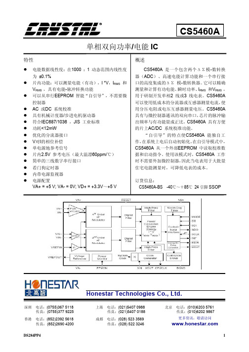
CS5463A中文资料手册pdf
魏德米勒交换机选型手册
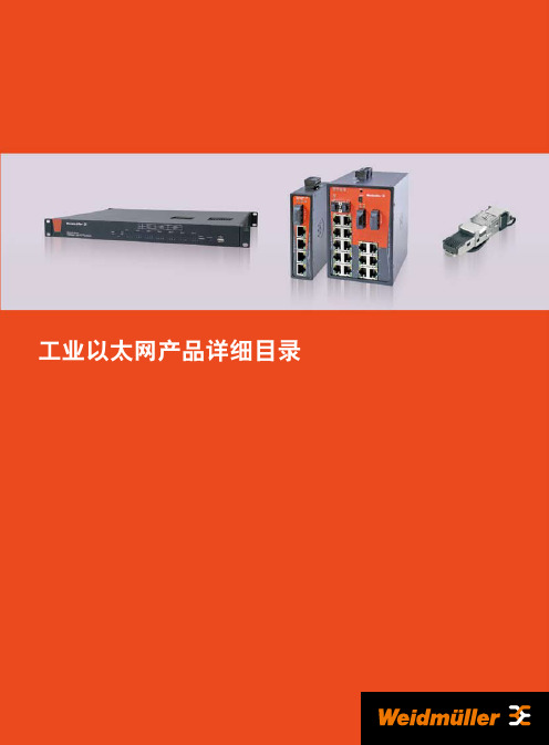
光纤中常用的光波长为1310nm、1550nm,以多模和单 模的方式传播。由于单模光纤在传输中光线没有反射,因此 具有更宽的传输频带和更大的传输容量,能够比多模光纤传 输更远的距离。
应用层 (HTTP,HTTPS,FTP,Telnet,SMTP)
传输层
IP 层
MAC 层 (HDLC,PPP,IEEE802.3/802.2, FDDL,ATM)
物理层 (IEEE802.3,802.5 FDDI,E1A/T1A,232,V.35, V.24)
各种软件,Email, WWW 浏览器等 TCP/UDP
PPP Point to Point Protocol 点到点协议 • 在点对点的链路上封装多协议数据包 • 实现在点到点连接之间的IP 通信 • 能在任何DTE/DCE之间实现通信 • 无速率限制
下图所示以太网TCP/IP模型和构件与开放式系统互连参考模型(OSI模型)对照表。
应用层 表示层 会话层 传输层 网络层 数据链路层 物理层
宽 无风扇外壳散热
工业级标准 小于300ms 20年以上
总之,商用以太网是为舒适的办公室环境而设计的,所 以不适合具有大负载、振动频繁、温度范围宽的工业环境。 由于在生产环境中工业网络必须具备较好的可靠性、可恢复 性和可维护性,而工业以太网设备在设计的时候就考虑到了 工业现场的复杂情况,从而能更加适应工业环境而发挥设备 的作用。
更多新产品敬请关注魏德米勒网站:
A.5
工业以太网的接口
RJ45接口
概述
在以太网中所有数据都被在物理层转化为电信号,用双 绞线传播到另一端后,数据链路层将这些物理层的电气信号 转换为用0、1二进制代码表示的数据帧,这就是交换机接到 的信息。
北京四方CSC-161A型线路保护运行规定
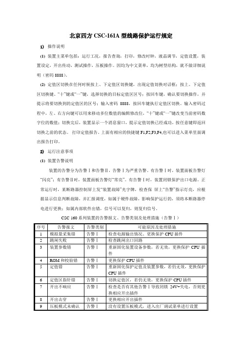
北京四方CSC-161A型线路保护运行规定1)操作说明(1)装置主菜单包括:运行工况,报告查询,打印,修改时钟,液晶调节,定值设置,装置设定,开出传动,测试操作,压板操作。
因均为中文菜单,均为树型结构,就不做详细说明(密码8888)。
(2)定值区切换在任何时候按上、下定值区切换键,出现定值切换对话框;按上、下定值区切换键、“十”键或“一”键,选择切换的目标定值区区号;按回车键,确认要切换操作,并提示将要切换到的定值区的区号;输入密码8888,按回车键执行定值区切换。
输入密码过程中,左、右方向键可以用来移动多位数值的编辑修改位,“十”键或“一”键改变当前密码数字位的数值;切换完后,装置显示一个消息窗口,提示定值切换已经成功,按任意键即返回切换之前的状态。
打印定值报告。
上面有相应的快捷键F1,F2,F3,F4,也可以进入菜单里面调出报告打印。
2)运行注意事项(1)装置告警说明装置的告警分为告警Ⅰ和告警Ⅱ,告警Ⅰ为严重告警。
有告警Ⅰ时,装置面板告警灯“闪亮”;有告警Ⅱ时,装置面板告警灯“常亮”。
有告警Ⅰ时,装置闭锁保护出口电源。
正常运行时,某断路器控制屏上发“装置故障”光字牌,检查保屏上“告警”指示灯亮,应根据显示信息判断故障,并汇报调度,如属于硬件故障,影响保护运行的,须将本断路器停电进行更换;如属内部软件出错,信号可以复归,则复归信号。
CSC-160系列装置的告警报文、告警类别及处理措施(告警Ⅰ)CSC-160系列装置的告警报文、告警类别及处理措施(告警Ⅱ)2)异常处理及事故分析(1)运行中电源指示灯熄灭,直流消失光字牌亮。
说明装置直流电源消失,应报告值班调度员,申请退出保护。
如果经检查运行人员无法处理,应通知检修人员处理;(2)当“交流电压断线”光字牌亮时,应立即报告值班调度员,然后检查交流电压失压原因,如运行人员无法处理,应申请调度退出保护并通知检修人员;(3)当打印报告中有TA断线时应立即报告值班调度员申请退出保护,并通知检修人员处理。
CJ1W模拟量使用手册
13
14 19 26 30 34 41 49 57
第3章 CJ 系列模拟量输入单元 . . . . . . . . . . . . . . . . . . . . . . . . . .
3-1 3-2 3-3 3-4 3-5 3-6 3-7 3-8 规格 . . . . . . . . . . . . . . . . . . . . . . . . . . . . . . . . . . . . . . . . . . . . . . . . . . . . . . . . . . . . 操作步骤 . . . . . . . . . . . . . . . . . . . . . . . . . . . . . . . . . . . . . . . . . . . . . . . . . . . . . . . . 元件和开关设置 . . . . . . . . . . . . . . . . . . . . . . . . . . . . . . . . . . . . . . . . . . . . . . . . . . 配线 . . . . . . . . . . . . . . . . . . . . . . . . . . . . . . . . . . . . . . . . . . . . . . . . . . . . . . . . . . . . 与 CPU 单元交换数据 . . . . . . . . . . . . . . . . . . . . . . . . . . . . . . . . . . . . . . . . . . . . . 模拟量输入功能和操作步骤 . . . . . . . . . . . . . . . . . . . . . . . . . . . . . . . . . . . . . . . . 调整偏移和增益 . . . . . . . . . . . . . . . . . . . . . . . . . . . . . . . . . . . . . . . . . . . . . . . . . . 处理错误和警报 . . . . . . . . . . . . . . . . . . . . . . . . . . . . . . . . . . . . . . . . . . . . . . . . . .
传感器库存资料- 霍尼韦尔压力传感器型号霍尼韦尔压力传感器1.pdf

霍尼韦尔压力传感器型号霍尼韦尔压力传感器 142PC01D,142PC02D,142PC03D,142PC05D,142PC15D,142PC30D,142PC15A,142PC30A,142PC30G,141PC01D,141PC02D,141PC03D,141PC05D,141PC15D,141PC30D,143PC01D,143PC02D,143PC03D,143PC05D,143PC15D,143PC30D,141PC01G,141PC02G,141PC05G,142PC01G,142PC02G,142PC03G,142PC05G,142PC15G,163PC01D36,163PC01D48,163PC01D75,164PC01D76,163PC01D37,163PC01D76,161PC01D36,162PC01D36,164PC01D36,189PC15GM,189PC100GM,189PC150GM,ASCX01DN,ASCX05DN,ASCX15AN,ASCX15DN,ASCX30AN,ASCX30DN,ASCX100AN,ASCX100DN,ASCX150DN,ASCX150AN,ASDX015A24R,ASDX030A24R,ASDX100A24R,ASDX001G24R,ASDX005G24R,ASDX015G24R,ASDX020G24R,ASDX100G44R,ASDX001D44R,ASDX005D44R,ASDX015D44R,ASDX030D44R,ASDX100D44R,40PC001G2A, 40PC015G2A, 40PC100G2A, 40PC150G2A, 40PC250G2A, 40PC500G2A, 4040 PC001G2A, 4040PC015G2A, 4040PC100G2 A, 4040PC150G2A, 4040PC250G2A, 4040PC500G2A. 微压传感器 CPCL04DC,CPCL10DC,CPCL04DTC,CPCL10DTC,CPXL04DTC,CPXL10DTC,CPXL01DC,CPXL10DC,XPCL04DC,XPCL10DC,XPCL04DTC,XPCL10DTC,XPX50D,XPXL04DC,XPXL10DC,XPXL04DTC,XPXL10DTC,XSXL04D,XSXL10D,XSCL04DC,XSCL10DC,SDXL005D4,SDXL010D,SLP004D,SLP010D,DCXL01DN,DCXL05DN,DCXL10DN,DCXL20DN,DCXL30DN,DC001NDC4,DC002NDC4,DC005NDC4,DC010NDC4,DC020NDC4,DC030NDC4,DC001NDR4,DC002NDR4,DC005NDR4,DC010NDR4,DC020NDR4,DC030NDR4,DC001NDR5,DC002NDR5,DC005NDR5,DC010NDR5,DC020NDR5,DC030NDR5,DC2R5BDC4,DC005BDC4,DC075BDC4,DUXL01D,DUXL05D,DUXL10D,DUXL20D,DUXL30D。
四方公司新老装置型号对照表201004

测控装置新型号装置有不同配置,具体请咨询我公司相关人员。
CSI-200EB
CSI-200ED
数字式非电量保护装置
CSC-336A1
CSC-336A2
CSC-336A3
CSC-336C1B
CSC-336F1
CSC-336F2
CSC-336C2B
CSC-336G1
CSC-336C3B
低压保护测控(A,B,E)
CSC101C/D
CSL101A/B-S
CSC101A/B-S
CSL102A/B-S
CSC102A/B-S
CSL109A
CSC109A
断路器保护、短引线保护、故障启动、过电压保101C
CSC122B
CSI121A
CSC121A
CSI123A/B
CSC123A
CSI125A
CSC125A
CSI126A
CSC126A
中压线路保护
CSL161/2/3/4
CSC161/2
部分老装置为19/2机箱;CSC163/7不能与老品配合使用。
CSL166/7/8/9
CSC166
CSL103C
CSC163
CSL103D
CSC167
变压器保护
CST141/143
CSC-326A/326B
注2:此表并未包括所有的新老型号装置。
注3:如果用新型号装置替换现场的老型号装置,一般须注意以下几点的不同:端子定义、定值、通信规约、通信口介质、打印机接口盒、开口尺寸、是否定制等。
电容器保护CSP216A(带接地选线功能、不平衡电流)
CSC221B
接地变CST312A
CSC241E
《Illustrator CS6中文版图形设计实战从入门到精通》读书笔记思维导图

111 利用图层制作 蒙版
112 应用图层设计 封面
113 制作 UV 印刷 工艺图层
114 认识动作
115 创建动作 116 应用剪切蒙版
第11章 混合和封套
01
117 直接 混合图形
02
118 复合 混合图形
04
120 混合 图形轮廓
06
122 制作 轨迹效果
03
119 沿路 径混合图形
05
05
43 移动对 象
01
45 变换对 象
02
46 旋转对 象
03
47 镜像对 象
04
48 缩放对 象
06
50 整形工 具
05
49 倾斜对 象
01
51 自由变 换工具
02
52 扭曲变 形对象
03
53 排列对 象
04
54 对象编 组与取消编 组
06
56 对象的 隐藏和显示
05
55 锁定与 解锁对象
第5章 填充和描边
87 绘制篮球 88 绘制爱心徽标
第8章 文字应用
01
89 输入文 字
02
90 输入区 域文字
03
91 输入路 径文字
04
92 置入与 粘贴文字
06
94 应用段 落面板
05
93 应用字 符面板
96 文字绕排方式
95 编辑文字
97 设计迎新春 POP 海报
第9章 符号、图表和样式
01
98 符号工 具
121 混合 开放路径
123 绘制花图形 124 立体艺术字
125 霓虹艺术字 126 闪闪的红星
128 用网格建立封 套
康佳电视说明书

康佳电视说明书康佳电视说明书篇一:康佳电视说明康佳“T”系列彩电简介在201X年春天,康家集团多媒体事业部以科技创新为动力,运用最新的数字视频处理技术开发出新一代“高清”数字电视P3460T、P3409T、P2902T、P2906T等系列新产品,为提升康佳品牌形象作出了新的努力。
为了配合作好新产品的推广和技术服务工作,现将P3460T系列彩电的电路结构特点和检修参考数据介绍如下。
康佳P3460T彩电的电路结构特点简介康佳P3460T系列彩电的核心电路主要由大规模数字处理芯片构成,其中包含视频信号数字处理芯片U1(DPTV-3D/MV);伴音信号数字处理芯片N205(MSP3463G);微处理控制系统N601(SDA555XFL);N602(AT24C16);以及扫描及视频处理N301(SDA9380)等集成电路。
为了保持电路简洁,合理利用有效空间,本机采用主电路板与单元电路板相结合的方式组成整机电路。
本机的印刷电路板包含主信号处理板、电源扫描伴音功放输出板、视放输出板、速度调制输出板、AV输入板、遥控按键输入板。
还有三个单元电路板通过多脚双排插座与主信号板相连。
即以SDA555XEL为核心的微处理控制单元电路板,通过XS001(64脚双排插座)与主电路板相连。
以DPTV-3D/MV为核心的视频信号数字单元电路板,通过X002、X003与主信号板相连。
以SDA9380为核心的扫描视频信号输出单元电路板通过X004与主信号板相连,为了帮组快速判断电路故障点,下列P3460T总线流程图与电路框图康佳“T”系列彩电故障检修 T系列机故障检修实例1 机型P2903T 故障现象: 伴音平衡失控分析与检修:开机后伴音平衡不起作用,拔掉XS202或XS203任一插排,另一声道也无伴音,用另一性能完好的TV信号处理板试机故障依旧,故障应在功放部分,检查功放外围元件无损坏,这时发现扬声器负极的两根黑线连接不正常,应连接左声道的黑线连到了右声道的负极,连接右声道的黑线连接在左声道的负极,将两根线正确连接后开机故障排除。
ASTM标准年鉴

ASTM标准年鉴(可提供印刷版、光盘版版和在线网络版)ASTM标准年鉴包括77卷,12000个标准,涉及130个产业领域。
除印刷版和光盘版外,也可提供两种格式在线网络版:Online Basic 和Online Plus。
Online Basic 仅能访问或获取到现行标准。
Online Plus不仅能访问或获取到现行标准,也能访问或获取到更新标准(显示与上次版本不同的变化);历史标准(以前的版本)和作废(不再使用的)标准。
各卷的说明如下。
如想了解各卷的详细说明,请访问ASTM网站()和检索ASTM标准年鉴(Annual Book of ASTM Standards)。
第1部分:钢铁产品卷01.01 钢—钢管,管道与配件966页;123个标准;2004年1月出版规定了高温作业、普通使用和特殊应用的钢管规范,规定了锅炉和过热管道、机械管道等的要求。
还包括阀门、法兰和其他压力容器配件的钢铸件规范。
卷01.02 铁铸件;铁合金752页;104个标准;2004年1月出版包括普通用、结构用和高低温用的钢铸件的规范和规程,也规定了合金铸件、铁铸件和配件及各种铁合金的标准。
卷01.03 钢—钢板、薄钢板、带钢、线材;不锈钢棒740页;95个标准;2004年2月出版包括钢板、薄钢板和带钢的各种机械特性要求和应用的规范,也详细规定了多种类型线材、工业筛的特性规范卷01.04 钢—结构钢、钢筋、压力容器用钢、钢轨686页;111个标准;2004年1月出版包括各种结构钢(包括高强度和低合金钢)要求的规范,也提供了锅炉和压力容器用的钢板和锻件、混凝土钢筋、预应力混凝土用钢和铁轨及附件的标准。
卷01.05 钢—棒材、钢锻件、轴承钢、钢链与弹簧804页;100个标准;2004年1月出版详细规定了特殊或普通应用的各种棒材特性的规范和试验方法,也提供了铁路用的碳钢车轴和钢轮箍的标准,还包括钢链、轴承钢和工具钢等的规范。
卷01.06 镀层钢材768页;115个标准;2004年2月出版确定了镀铝或镀锌钢的特性要求和镀锡薄钢板轧制品的质量要求,规定了以镀铝和镀锌为主的镀层钢丝的特性。
松下 高清摄像机 HC-PV100GK 使用说明书
电源插头是断路装置。 安装本机,使得可以立即从电源插座上拔下电源插头。
本机供在温和及热带气候地区使用。
∫ 关于电池
警告 电池有发生火灾、爆炸和灼伤的危险。请勿对其拆卸、加热至 60 oC 以上 或焚烧。
间接触。
如果在沙地或尘土较多的地方使用本 机,例如在沙滩上,请勿使沙子或细 小的灰尘进入到本机的机身和端口内。 另外,还要使本机远离海水。 ≥ 沙子或尘土可能会损坏本机。(插
入及取出记忆卡时务必要小心。) ≥ 如果海水溅到了本机上,请用拧干
的布将水擦去。 然后,用一块干布 重新擦拭本机。
携带本机时要小心,请勿跌落或碰撞 本机。 ≥ 强烈的撞击可能会损坏本机的外
壳,使其发生故障。 ≥ 携带本机时,请握紧手带或肩背
带,小心对待。
清洁 ≥ 清洁之前,请取下电池或从 AC 电源
插座上拔开 AC 电缆,然后用软干 布擦拭本机。 ≥ 如果本机非常脏,请将布用水浸湿 后用力拧干,然后用湿布来擦拭本 机。 之后,再用一块干布擦干本机。 ≥ 使用汽油、涂料稀释剂、酒精或洗碟 剂可能会造成摄像机的机身发生变化 或表面涂层剥落。 请勿使用这些溶剂。 ≥ 使用化学除尘布时,请按照此布随 附的说明书进行操作。
外出录制时,请准备好备用电池。 ≥ 请准备想要录制的时间的约3至4倍的
电池。 在寒冷的地方录制会缩短可以 录制的时间,例如在滑雪场录制。
如果不小心跌落电池,请检查电池的 电极是否损坏。 ≥ 在端子部处于变形的状态下安装到
本机上时,本机可能会被损坏。
5
SQT1408
请勿将废弃的旧电池掷入火中。 ≥ 加热电池或将其掷入火中可能会引
Strike Eagle 1-6x24 和 1-8x24 射线光圈商品说明书

PRODUCT MANUALStrike Eagle ® RiflescopeSpeed and versatility—that’s what 1x variable optics offer AR shooters who need to engage targets from point-blank out to extended range, and that’s exactly what you get with the redesigned Strike Eagle ®. Plus, with an updated reticleand a screw-in throw lever, you’ll be on target even faster.Thread-In Throw LeverElevation TurretWindage TurretIllumination DialMagnification Adjustment RingFast Focus EyepieceOcular LensObjective Lens1-6x241-8x24WATERPROOF IPX7IPX7FOGPROOF Nitrogen Gas Purged Nitrogen Gas Purged LENGTH10.5" (266.7mm)10" (254mm)MOUNTING LENGTH 6.6" (167.6mm) 6.4" (162.6mm)WEIGHT 18.5 oz. (524.5 g)17.6 oz. (499 g)EYE RELIEF 3.5" (89mm)3.5" (89mm)FIELD OF VIEW 1x mag: 116.6ft @ 100yds (22°)1x mag: 109ft @ 100yds (20.6°)6x mag: 19.2ft @ 100yds (3.76°)8x mag: 14.4ft @ 100yds (2.75°)BATTERYCR2032CR2032STRIKE EAGLE ® MODELSMOAADJUSTMENT GRADUATION 1/2 MOA ELEVATION ADJUSTMENT 140 MOA WINDAGE ADJUSTMENT 140 MOA TRAVEL PER ROTATION44 MOARear Mounting Length 2.1" / 53.3mmEyepiece 3.9" / 99mm1.7" /43.2mm1.18" /30mmTube Diameter Eyepiece Diameter Front Mounting Length2.9" / 73.7mm10.5" / 266.7mmRear Mounting Length 1.8" / 45.7mmEyepiece 3.5" / 89mm1.7" /43.2mm1.18" /30mmTube Diameter Eyepiece Diameter Front Mounting Length2.8" / 71.1mm10" / 254mmImages are for representation only. Product may vary slightly from what is shown.Reticle Focal PlaneAll riflescope reticles are either First Focal Plane (FFP) or Second Focal Plane (SFP), depending on the reticle’s location within the riflescope. This riflescope features a SFP reticle. Second Focal Plane ReticlesSFP reticles are located near the scope’s eyepiece behind the image erecting and magnifying lenses. This style of reticle does not visually change in size when you change the magnification. The advantage of an SFP reticle is that it always maintains the same ideally-sized appearance when shooting. Be aware that the listed reticle subtensions used for estimating range, holdover, and wind drift correction are only accurate at the highest magnification.Ocular FocusThe ocular focus is essentially a one-time adjustment used to focus the reticle for maximum sharpness. This adjustment is slightly different for every shooter. A clearly focused reticle is a critical component for accurate shooting.Ocular Focus—Reticle Focus AdjustmentYour riflescope uses a fast focus eyepiece designed to quickly and easily adjust the focus on the riflescope’s reticle. To adjust the reticle focus:1. Look through the riflescopeat a blank white wall or upat the sky.2. Turn focus knobfully outward(counterclockwise).3. Slowly turn the eyepiece focus knob inward until thereticle image is as crisp as possible.TIP: Make this adjustment by taking short, quick glances through the scope as your eye will try to compensate for an out-of-focus reticle.WARNING: Looking directly at the sun through ariflescope, or any optical instrument, can cause severe and permanent damage to your eyesight.MagnificationThe magnification adjustment isused to change the riflescope’smagnification level, or “power,”adjusting from low to highmagnification depending on theshooter’s preference.Magnification AdjustmentRotate the magnification ring to the desired magnification.Throw Lever InstallationThread in the included throw lever as shown until the throw lever is secured.Arc MeasurementsThis scope uses Minute of Angle (MOA) arc measurements.Minute of Angle (MOA) arc measurements are based on the concept of degrees and minutes in a circle. There are 360° in a circle, and 60 minutes in a degree. One MOA will always subtend 1.05” for each 100 yds. of distance. In other words, if a rifle and scope were zeroed at 100 yds. and the target is moved out to 200 yds., the bullet’s impact will be 1.05” (1 MOA) lower on the target at 200 yds. Most riflescopes using MOA turrets will adjust in 1/4-minute increments. Adjustments can be felt by mechanical “clicks,” which subtend .26” for each 100 yds. of distance. Note: These measurements are often rounded down to 1 MOA equaling 1 inch at 100 yards, and each adjustment(each mechanical click) equaling 1/4 inch at 100 yards.Bullet Drop1 Degree60 Minutes-of-Angle(MOA)MOATurretsUse turrets to adjust the bullet’s point-of-impact. There are two turrets on your riflescope. The turret on the top of the riflescope is the Elevation Turret and is used to adjust the point-of-impact up and down. The turret on the right-hand side of the riflescope is the Windage Turret and is used to adjust the point-of-impact left and right. Vortex ® riflescopes incorporate precision, finger adjustable Elevation andWindage Turrets with audible and tactile clicks.Elevation TurretWindage TurretMOA Models1 Click = 0.5 MOATurret AdjustmentsYour riflescope features adjustable elevation and windage turret dials with audible and tactile clicks. Each click moves the bullet’s point of impact 1/2 MOA.To make turret adjustments:1. Remove the turret caps.2. Following the directional arrows, turn the dials in thedirection you wish the bullet’s point of impact to go.3. When finished adjusting, replace the turret caps.Image Sharpness—ParallaxYour scope comes equipped with a fixed parallax setting. The parallax is set for 100 yards.Battery Installation/ReplacementTo install/change the battery, unscrew the illumination dial’s outer cap. Install a new CR2032 battery with numbers facing out.A spare battery may be stored inside the windage cap, if desired, as shown here.Replacing the Battery:1. Unscrew the outercap with a coin.2. Remove theCR2032 battery.3. Replace with a newCR2032 battery with the + side facing out.Illumination – Side Illumination ControlYour riflescope uses a variable intensity reticleillumination system to aid in low-light performance. A rotary dial is mounted on the left-hand side of the riflescope for easy access.To activate/adjust the illumination, rotate the adjustment dial in either direction. The illumination dial allows for 11 levels ofillumination intensity.Battery CapTo get the best performance from your Vortex ® riflescope, proper mounting is essential. Although not difficult, you must follow the correct steps. Please follow the instructions below for the proper scope mounting procedure, or go to for a video tutorial.If you are unsure of your abilities, use the services of a qualified gunsmith.Riflescope Mounting Checklist;Gun vise or a solid platform/rest for your rifle ;Scope rings ;Torque wrench;Reticle leveling tool, feeler gauges, or weight on a rope Recommendation: Pick up the Vortex Torque Wrench Mounting Kit, which comes with the complete set of bits needed to install Vortex ® scopes and rings!Rings and BasesYour Vortex ® riflescope features a 30mm main tube. Be sure to select a base, and matching rings appropriate for your rifle,and mount according to the manufacturer’s instructions.Note: Vortex ® Optics recommends not exceeding 18 in./lbs.(inch/pounds) of torque on the ring screws.Eye Relief and Reticle AlignmentAfter installing the bottom ring halves on the mounting base, place the riflescope on the bottom ring halves and loosely install the upper ring halves. Before tightening the scope ring screws, adjust for maximum eye relief to avoid injury from recoil:1. Set the riflescope to its highest magnification.2. Ensure the riflescope is centered in the rings.3. While viewing through the riflescope in a normal shootingposition, slowly slide the riflescope back toward yourface. Pay attention to the field of view. Stop sliding the riflescope back as soon as you see the full field of view. 4. Without disturbing the front-back placement, rotate theriflescope until the vertical crosshair exactly matchesthe vertical axis of the rifle.NOTE: Using a reticle leveling tool, a plumb bob, abubble level, or an adjustable set of feeler gauges placed between a one-piece base and the flat bottom of theriflescope’s center section will help with this procedure. 5. After aligning the reticle, tighten and torque the ringscrews down per the manufacturer’s instructions. Usecaution and do not overtighten.Bore SightingInitial bore sighting will save time and money at the range. Do this by using a mechanical or laser bore sight according to the manufacturer’s instructions, or by removing the bolt and sighting through the barrel on some rifles.To Visually Bore Sight a Rifle:1. Place the rifle solidly on a rest and remove the bolt.2. Sight through the bore at a target approximately 100yards away.3. Move the rifle and rest until the target is visuallycentered inside the barrel.4. With the target centered in the bore, make windage andelevation adjustments until the reticle crosshair is alsocentered over the target.Final Range Sight-InAfter the riflescope has been bore-sighted, final sight-in should be done at the range using the exact ammunition you expect to use while hunting or shooting competitively. Sight-in and zero the riflescope at the preferred distance. 100 yards is the most common zero distance, although you may prefer a 200-yard zero for long-range applications.1. Following all safe shooting practices, fire a three-shotgroup as precisely as possible.2. Next, adjust the reticle to match the approximate centerof the shot group. Be sure to read pages 12–13 prior to making adjustments.NOTE: If the rifle is very solidly mounted and cannot bemoved, simply look through the scope and adjust the reticle until it is centered on the fired group.3. Carefully fire another three-shot group and see if thebullet group is centered on the bullseye. This procedure can be repeated as many times as necessary to achieve a perfect zero.Indexing the Elevation and Windage TurretsStrike Eagle ® riflescopes feature Elevation and Windage Turrets that allow you to re-index the zero indicator after sight-in without disturbing your zero setting. Though not a required process, re-indexing the turrets allows you to quickly return to your original zero setting if you dial temporary corrections in the field.To Index the Turrets:1. After completing the final sight-in, remove theturret cap(s).2. Without rotating the turret, twist the dial to reposition itwith the “0” mark aligned with “Up” on the scope housing.3.Replace the turret cap(s).CleaningThe Strike Eagle ® riflescope requires very little routine maintenance other than periodically cleaning the exterior lenses. The scope’s exterior may be cleaned by wiping with a soft, dry cloth. When cleaning the lenses, be sure to use products that are specifically designed for use on coated optical lenses.• Be sure to blow away any dust or grit on the lenses prior to wiping the surfaces.• Using your breath, or a very small amount of water or pure alcohol, can help remove stubborn things like dried water spots.LubricationAll Strike Eagle ® components are permanently lubricated, so no additional lubricant should be applied. If possible, avoid exposing your riflescope to direct sunlight or any very hot location for long periods of time.Note: Other than to remove the turret caps and batterycap, do not attempt to disassemble any components of the riflescope. Disassembling of riflescope may void warranty.Please check the following items prior to returning a riflescope for service.Sighting-In ProblemsMany times, problems thought to be with the scope are actually mounting problems. Be sure the mounts are properly torqued to the rifle and the scope is secured so it doesn’t twist or move in the rings. An insufficient windage or elevation adjustment range may indicate problems with the base mount, base mount holes drilled in the rifle’s receiver, or barrel/receiver alignment.Grouping ProblemsThere are many issues that can cause poor bullet grouping.• Be sure that rings are correctly torqued to 15-18 in/lbs.• Be sure that all screws on rifle’s action areproperly tightened.• Be sure rifle barrel and action are clean and free of excessive oil or copper fouling.• Maintain a good shooting technique and use a solid rest.• Some rifles and ammunition don’t work well together—try different ammunition and see if accuracy mon ProblemsPoint of Impact Changes Drastically After Turret Adjustment • Verify that the ring screws are not over torqued. Ring screws should only be torqued to 18 in/lbs, and no thread locking component applied. Over torqueing the ring screws will cause excess pressure on the tube, which will cause problems when adjusting the reticle.Point of Impact is Inconsistent• Ensure the cantilever mount/rings are mounted onlyto the receiver. The cantilever mount/rings need tobe mounted to one, solid surface. Make sure that the forward connection of the cantilever mount, or ring, is not mounted to the fore end of the rifle.• Verify that the ring screws are not over torqued. Ring screws should only be torqued to 18 in/lbs, and no thread locking component applied. Over torqueing the ring screws will cause excess pressure on the tube, which will cause problems when adjusting the reticle. Insufficient Adjustment Ranges• Check that you have the proper base and rings for your rifle and for your size. If you need assistance, contact a local gunsmith to be properly fitted to your rifle and scope.• Once you have verified that you have the correct base and mounts, and that you have been properly fitted to your gun, make sure you followed the correct mounting procedure. See Riflescope Mounting section for this procedure. Reticle Appears to Come In and Out of Focus• Check and reset the ocular focus of the reticle for the shooter’s eye. See Riflescope Adjustments section, Ocular Focus – Reticle Focus Adjustment.VIP WARRANTY OUR UNCONDITIONAL PROMISE TO YOU.We promise to repair or replacethe product. Absolutely free.Unlimited.Unconditional.Lifetime Warranty.Learn more at ************************•800-426-0048 NOTE: The VIP Warranty does not cover loss, theft, deliberate damage, or cosmetic damage not affecting product performance.M-00280-0© 2020 Vortex Optics® Registered Trademark and TM Trademark of Vortex Optics。
中兴S330硬件手册及应用
资料名称
产品版本
V1.2
您单位安装该设备的时间
ZXMP S330(V1.2)基于 SDH 的多业务节点设备 硬件手册
资料版本
20060325-R1.0
为了能够及时与您联系,请填写以下有关您的信息
姓名
单位名称
邮编
单位地址
电话
好
较好
一般
较差
差
总体满意
工作指导
您对本资料 的评价
查阅方便 内容正确 内容完整
“第 3 章 单板”介绍 ZXMP S330 的单板命名、单板结构、ZXMP S330 的各功 能单元,并介绍这些功能单元对应单板的应用环境、原理、功能、面板及接口。
“附录 A 术语”,解释本手册中出现的部分术语。 “附录 B 缩略语”,列出本手册中所涉及缩略语的中文释义和英文全称。
本书约定
本书采用以下标志来表示在操作过程中应该特别注意的地方。
ZXMP S330(V1.2) 基于 SDH 的多业务节点设备
硬件手册
中兴通讯股份有限公司
ZXMP S330(V1.2)基于 SDH 的多业务节点设备 硬件手册
资料版本 20060325-R1.0 产品版本 V1.2
策 划 中兴通讯学院 文档开发部 编 著黄演 审 核汤闯 **** 中兴通讯股份有限公司 地址:深圳市高新技术产业园科技南路中兴通讯大厦 邮编:518057 技术支持网站: 客户支持中心热线:(0755)26770800 800-830-1118 传真:(0755)26770801 E-mail:doc@zteቤተ መጻሕፍቲ ባይዱ **** 编号:sjzl20060327
1. 《Unitrans ZXMP S330(V1.2)基于 SDH 的多业务节点设备 技术手册》 介绍设备的体系结构、系统特点、系统功能、技术指标、应用示例。
PK步进电机参数

步 进 电 动
机 ■品名的阅读方法
●标准 P型 · 大惯性型
PK 2 2 3 P B
2相步进电动机 PK系列
2相 电动机安装尺寸 电动机外壳 P∶标准P型
2∶28mm
长度
J ∶大惯性型
3∶35mm
4∶42mm
6∶60mm
A∶单转轴 B ∶双转轴
●标准型 · 高分辨率型
PK 2 6 6 M - 0 1 B
2相步进电动机 2相 电动机安装尺寸 电动机外壳 电动机分类 A∶单转轴
PK系列
2∶28mm
长度
B ∶双转轴
SG∶SH减速机型 减速比
◇安装尺寸 42mm、60mm、90mm
PK 2 6 4 A 1 - SG 10
2相步进电动机 2相 电动机安装尺寸 电动机外壳
PK系列
4∶42mm
长度
6∶60mm
9∶90mm
可轻易固定标准型 与减速机型电动机。
(➜ C-203页)
弹性联轴器(另售)
高精度定位用的无齿隙 联轴器。
(➜ C-192页)
制振器(另售)
可有效抑制步进电动机的 振动及改善高速性。
(➜ C-201页)
+
(另售)
电动机安装底座 PAL2P-2
弹性联轴器 MCS2006F04
制振器 D6CL-6.3F
●上述系统构成仅为一例,也可依需要设计其它各种组合。。
●大惯性型
品名(单转轴) PK264JA PK266JA PK267JA PK269JA
品名(双转轴) PK223PB PK224PB PK225PB PK233PB PK235PB PK244PB PK246PB
品名(双转轴) PK243-01B PK243-02B PK243-03B PK244-01B PK244-02B PK244-03B PK244-04B PK245-01B PK245-02B PK245-03B PK256-02B PK258-02B PK264-01B PK264-02B PK264-03B PK266-01B PK266-02B PK266-03B PK268-01B PK268-02B PK268-03B PK296-01B PK296-02B PK296-03B PK299-01B PK299-02B PK299-03B PK2913-01B PK2913-02B
- 1、下载文档前请自行甄别文档内容的完整性,平台不提供额外的编辑、内容补充、找答案等附加服务。
- 2、"仅部分预览"的文档,不可在线预览部分如存在完整性等问题,可反馈申请退款(可完整预览的文档不适用该条件!)。
- 3、如文档侵犯您的权益,请联系客服反馈,我们会尽快为您处理(人工客服工作时间:9:00-18:30)。
Software Life Cycle
1. 2. 3. 4. 5. 6. Specify the problem requirements. Analyze the problem. Design the algorithm to solve the problem. Implement the program. Test and verify the completed program. Maintain and update the program.
Algorithm
• Three basic forms of control 1. Sequential - one step after another 2. Selection - choose one of many alternatives 3. Repetition - one or more steps repeatedly
Problem Analysis and Spec.
• Determine its input
– what information is given – what items are important to solving problem
• Determine its output
– what information must be produced to solve the problem
Program Maintenance
• • • • Programs survive for many years New features must be added Laws, rules, and procedures change Hardware changes
• e.g. Year 2000 problem
• Determine scope of the problem
– questions, questions, and more questions
Algorithm Design
• Procedure to convert inputs to outputs • Uses step-by-step process • Top-down step-wise refinement • Produce pseudo-code or flowchart
START GET NUMBER ADD NUMBER 10 NUMBERS?
YES
NO
DIVIDE BY 10 PRINT RESULT END
Program Coding
• Program should be correct, readable, and understandable • Simple and clear - no tricks • Modular - program and test subtasks of overall problem separately • Conforms to syntax of language
Program Formatting
• Spaces between items in statements
– between variables and operators
• Blank lines between major sections
– each subpart separated from others
• Good indentation
– indent staariable names
– Distance and Time instead of d and t
Execution and Testing
• Test each unit separately before combining • Use expected data with known result • Use unexpected data to check for problems • Validation - tested with several sets of test data, but never can tell if absolutely valid.
CS 161 Lecture 4
Martin van Bommel
Program Development
• Software Engineering • study and use of techniques for programming and problem solving • Software Life Cycle • software development goes through cycles, where begins again when software outdated
