UNIK 5000--2011-4-26
华迪士汽车前速快挂包QH5000用户手册说明书
b. Remove the three 8 mm flange bolts from each hitch pivot, and remove the pivots.
c. Install 22.1 mm diameter hitch pivots in the rear mounting holes, as shown, using the 8 mm flange bolts that were removed from the original hitch pivots.
greater risk of striking an object or causing injury. l If you hit an object, stop the engine immediately, and check the attachment. Damaged
equipment may increase the possibility of injury during operation. l When operating the tractor, always raise the attachment if it is not in use. l Stop the tractors engine whenever you leave the operators position to make any inspection,
This word means:
Your Quick-Hitch, tractor, or other property can be damaged if you don’t fo.
kv-5000

进行简易轴控制,无需定位单元。
CPU 内置 2 轴定位功能
马达控制功能
启动时间仅 30 µs CPU 内置的超高速运行
缩短装置的生产间隔时间.提高生产率。
缩短生产间隔时间
←高速
KV-3000
以往的产品
(KV-700 的 2 倍)
专用定位参数窗口
只需要在表格内输入参数,而不必进行复杂的赋值语句编程 只要用 CM 显示就可以确认每个参数被分配到哪个软元件。
内置 2 通道马达控制功能,可实现对马达进行 位置控制或速度控制的功能
❚ 位置控制
❚ 速度控制
0 Hz
50 kHz 30 kHz
20 kHz
5 kHz
0 Hz
即使是只有一个 CPU 的系统也可以用 “超级访问窗口监控”进行运行状态监控
X 轴 M 代码、 Y 轴 M 代码、 X、Y 轴点、 位置、速度显示 位置、速度显示 速度显示
定位
1〜5 21〜25
输入
R000 〜
R009
○
7〜15
R010 输入 〜
5
软件
规格
CPU 技术
高性能的 CPU 内置功能,羡煞同侪
CPU 内置功能扩展至网络领域
CPU 内置 Ethernet/ FL-net 功能
CPU 单元 KV-5000 标配有 Ethernet 端口应 用极其广泛,诸如和上位 PC 间的通信或 PLC 间的链接、经由网络的调试等。可实现 的应用极其广泛。
全新
16 轴省配线型 定位·动作单元 KV-ML16V
全新
2 轴脉冲列 定位·动作单元 KV-MC20V
全新
4 轴脉冲列 定位·动作单元 KV-MC40V
汽车维修 项目二 汽车5000 km维护
任务2 5000km维护准备工作
4.打开发动机舱盖,安装外三件套。 (1)拉起发动机舱盖释放
杆,如图1所示。 (2)打开发动机舱盖,如
图2所示。
26 项 目 二 汽 车 5 0 0 0 k m 维 护1-拉起发动机舱来自释放杆2-打开发动机舱盖
任务2 5000km维护准备工作
4.打开发动机舱盖,安装外三件套。 (3)安装车辆外三件套
在车辆维护中,维修技师必须熟悉维护车辆的基本功能操作,使 车辆维护工作能安全、高效、顺利地进行。
15 项 目 二 汽 车 5 0 0 0 k m 维 护
任务2 5000km维护准备工作
知识准备 一、维护工位的准备
1.准备相关材料和设备 准备车轮挡块、举升机支撑垫块、尾气收集装置、压缩空气、照明
设备等,如图1和图2所示。
1-车轮挡块、举升机支撑垫块
2-压缩空气源和照明电源
16 项 目 二 汽 车 5 0 0 0 k m 维 护
任务2 5000km维护准备工作
2.准备工具车、零件车 车辆举升工位如图所示,工
具车、零件车停放在工位中的固 定位置。
17 项 目 二 汽 车 5 0 0 0 k m 维 护
车辆举升工位
任务2 5000km维护准备工作
35 项 目 二 汽 车 5 0 0 0 k m 维 护
1-阅读灯 2-阅读灯开关
任务3 灯光信号的检查与维护
2.车厢灯 车厢灯位于前排或车厢中部
的车厢顶部,上下车时,由门控 开关控制自动开启,并延迟一段 时间后关闭,如图1所示。门控 开关位于车门与车身结合部位, 如图2所示,用于监控车门是否 处于关闭状态。
5 项目二 汽车5000km维护
任务1 维护接车单的识读与填写
桥梁施工台帐

24 1-6 1.2 -32.634 -32.916 0.366 33 35.33 35.612 摩擦桩 2009/5/28 Ⅰ 2009/5/27 2.696 2009/5/27 100 K39+737小桥R
第 3 页,共 21 页
沿海高速公路沧州段四标五工区
墩 台 号
序 号
桩基施工台帐
桩基 编号
第 1 页,共 21 页
沿海高速公路沧州段四标五工区
墩 台 号
序 号
桩基施工台帐
桩基 编号
直径 (m)
设计孔底 实测孔底 标高(m) 标高(m)
设计桩 顶标高
(m)
设计 桩长 (m)
设计孔 实测孔 深(m) 深(m)
桩基 类型
浇筑日期
检测 类别
开孔日期
护筒顶标 高(m)
终孔日期
计量 情况 (%)
桥梁名称
3 0
4
0-3 1.2 -27.097 -27.377 2.903 30 30.587 30.867 摩擦桩 2009/6/14 Ⅰ 2009/6/13 3.49 0-4 1.2 -27.097 -27.312 2.903 30 30.398 30.613 摩擦桩 2009/6/9 Ⅰ 2009/6/8 3.301
42 1-6 1.8 -51.652 -52.23 1.348 53 54.422 55 摩擦桩 2009/10/23 Ⅰ 2009/10/20 2.77 2009/10/22 100 北疏分离立交R
43 2-1 1.8 -51.302 -51.768 1.698 53 54.234 54.7 摩擦桩 2009/8/2
36 0-b-6 1.3 -42.221 -42.617 -0.221 42 44.904 45.3 摩擦桩 2009/8/15 Ⅰ 2009/8/14 2.683 2009/8/14 100 北疏分离立交R
GE-UNIK5000压力传感器说明书

8
Isolated/Configurable
7 to 36
See below See below
(4 wire)
9
Configurable (3 See below
^ with a 10 volt supply mV output sensors give 100 mV over the full scale pressure.
Expertise
We have the people and the knowledge to support your needs for accurate and reliable product performance; our team of experts can help you make the right sensor selection, guiding you and providing the help and tools you need. It is important to ensure that the sensor material and performance selected are suitable for your application.
Barometric Ranges Barometric ranges are available with a minimum span of 350 mbar (5.1 psi)
Non Zero Based Ranges Non zero based ranges are available. Please contact GE Sensing to discuss your requirements
Isolated/Configurable (Option 8) or Configurable (Option 9) Any pressure signal output configurations will be available, subject to the following limitations: • Minimum span: 2 V • Maximum span: 20 V • Output limits: ±10 V • Maximum zero offset: ± span • Output voltage range can be specified to a resolution of 0.1 V Reverse output response to pressure is available. The output will continue to respond to 110% FS. i.e. if a 0 to 10 V output is specified, the output will continue to increase proportionally to applied pressure until at least 11 V. Current consumption is <20 mA @ 7 Vdc supply, reducing to <5 mA @ 32 Vdc supply. On startup <100 mA drawn for 10 ms typically. Shunt calibration: not available with reverse output. Note: Restricted to 80°C (176°F) for these options.
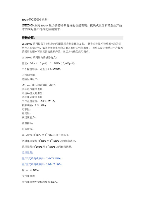
druckUNIK5000系列
druckUNIK5000系列
UNIK5000系列druck压力传感器具有好的性能表现,模块式设计和精益生产技术的满足客户特殊的应用需求。
详情介绍:
UNIK5000系列提供了高性能的可配置压力测量解决方案。
德鲁克硅技术和模拟电路的优势使其在稳定性、低功率和频率响应方面具有好的性能表现。
模块式设计和精益生产技术的采用使用户可以灵活的选择产品,满足其特殊的应用需求。
UNIK5000系列压力传感器特点:
量程:7kPa (1.0 psi) ~ 70MPa(10,000psi);
三个精度等级:可至±0.04%FSBSL;
不锈钢结构;
危险区域证书;
mV、mA、电压和可调电压输出;
多种电气接口选顶;
本质**型及隔爆型;
多种压力接口选顶;
工作温度范围:-55~+125°C;
频率响应:3.5 kHz;
可靠性;
稳定性;
高过压能力;
测量指标;
压力量程:
表压量程:0~7kPa至0~7MPa之间任意选择;
密封压力量程:0~1MPa至0~70MPa之间任意选择;
绝压量程:0~10kPa至0~70MPa之间任意选择;
差压量程:
湿/干式单向或双向:7kPa~3.5MPa;
湿/湿式单向或双向:35kPa~3.5MPa;
静压:大7MPa;
大气压量程:
大气压量程小量程跨度为35kPa;
复合量程:
复合压力量程也可供选择;。
UNITROL5000
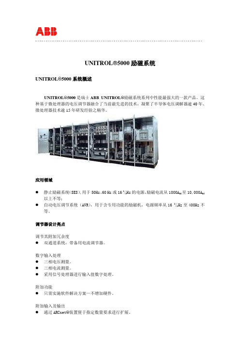
UNITROL®5000励磁系统UNITROL®5000系统概述UNITROL®5000是瑞士ABB UNITROL®励磁系统系列中性能最强大的一款产品。
这种基于微处理器的电压调节器融合了当前最先进的技术,凝聚了半导体电压调解器逾40年、微处理器技术逾15年研发经验之精华。
应用领域●静止励磁系统(SES),用于50Hz、60 Hz或16 2/3Hz的电源,励磁电流从1000A DC至10,000A DC以上不等;●自动电压调节系统(AVR),用于含专用功能的励磁机,电源频率从16 2/3Hz至400Hz不等。
调节器设计亮点调节其附加冗余度●双通道系统,带备用电流调节器。
数字输入处理●三相电压测量。
●三相电流测量。
●采用信号处理器进行输入值数字处理。
附加功能●只需实施软件解决方案—不增加硬件。
附加输入及输出●通过ARCnet®装置便于指定数量要求进行扩展。
●数字、模拟输入输出。
事件与故障记录●提供实时标记。
●可实现远程征询。
功率部分的设计亮点功率整流器冗余度●最多可并联8台功率整流器。
●功率整流器的冗余度完全独立于调节器配置。
功率整流器智能化电子器件●功率整流器之间实现电流动态平衡。
●四象限运行(励磁电流可为负)。
●可控硅电流监测。
●风扇控制与监测。
●熔断器、功率整流器温度及冷却风流监测。
●整流桥电流显示。
对系统的通信●支持上位控制系统最常用的协议。
●控制室可设第二控制面板,最长距离可达数百米。
●ABB服务部可利用PC软件“AVRview”通过因特网实施远程诊断。
UNITROL®5000系统配置UNITROL®5000采用模块化“组块系统”设计。
80%以上的系统由通过型式试验的组件构成,既提升了产品质量,又可缩短交货周期。
功率部分包含一台或多台可控硅功率整流器、交流或直流端磁场断路器、起励电路及带Crowbar跨接器的固态灭磁系统。
Unitrol 5000励磁调节器过励限制与励磁绕组过负荷保护的配合分析

(Ie*2-1)×t=33.75 Ie*>1.1
(7)
GB/T 7064—2008《隐 极 同 步 发 电 机 技 术 要 求》规 定 发
电 机磁场绕组应具有式(7)规定的过电流能力,时间从10~
120 s。 而发电机厂家阿尔斯通给出的发电机磁场绕组过电流
的反时限计算公式为:
(Ie*2-1)×t=33.95 Ie*>1.1
×T
(1)
式 中 ,Ie_max*为 顶 值 励 磁 电 流 标 幺 值 ;Ie_th*为 连 续 励 磁 电 流 标 幺
值;Ie*为实际励磁电流标幺值;T为强励时间;t为实际励磁电流
对应的反时限动作时限。
GB/T 7409.3—2007《同步电机励磁系统大、中型同步发
电机励磁系统技术要求》第5.2条规定:“当同步发电机的励磁
120
Sheji yu Fenxi◆设计与分析
表1 过励限制、保护和励磁绕组过负荷动作值与动作时限
励磁电 第一代过励 第二代过励 第三代过励 励磁绕组过 励磁绕组过 流倍数Ie* 限制器t1/s 限制器t2/s 限制器t3/s 负荷保护t4/s 负荷能力t5/s
2.08
8.59
8.95
9.02
10.15
1.46
46.18
30.27
26.51
29.83
1.25
150.90
79.15
53.33
60.00
1.13
520.46
417.04
108.34
—
10.21 30
(4)
Байду номын сангаас
如果Ie_th*取1,式(3)就和第三代过励限制器反时限计算公
式式(5)相同,但它同时是过励限制器的启动值,不满足“当同
UNITROL5000型励磁小电流试验详细步骤

UNITROL 5000型励磁调节器励磁小电流试验详细步骤河北省电力科学研究院目录1、概述 (4)2、试验目的 (4)3、试验依据 (4)4、试验仪器 (5)5、ABB电气UNITROL 5000型励磁调节器开环试验详细步骤 (6)6、试验结果分析 (8)7、结论 (11)8、相关技术问答 (12)8.1 什么是励磁系统的小电流试验? (12)8.2励磁系统小电流试验的作用是什么? (12)8.3 如何进行励磁系统小电流试验? (13)8.4 为什么小电流试验没有直流输出? (13)8.5 如何分析励磁系统小电流试验的录波图? (13)1、概述近年我国电源建设突飞猛进,在建发电机机组的单机容量迅速提高,发电机的额定励磁电压和励磁电流都越来越大,励磁系统的安全性越来越显得特别重要,在早期的静态调试实验以及机组大修试验中,励磁系统开环试验(小电流试验)是一项非常重要的试验。
励磁系统开环试验需要外接380V的交流电源、阻值恰当且功率合适的电阻负载以及录波器等设备。
为了解决励磁系统开环试验现场准备工作的繁琐性,我们研发了EXOM-Ⅱ型励磁系统开环测试仪,由电源变换模块、负载电阻和显示存储装置组成,实现了励磁系统开环测试的数字化、小型化、便携化。
经现场使用后,EXOM-Ⅱ型励磁系统开环测试仪避免了现场试验准备的繁琐工作,大大节约了励磁系统开环试验的时间,提高了现场试验接线的安全可靠性,进一步降低了试验人员的劳动强度。
2、试验目的励磁系统开环试验的目的是创造一个模拟的环境检查励磁调节器的基本控制功能,脉冲可靠触发的能力,晶闸管完好性等。
同时检查同步信号回路的相序和相位,查看调节器的触发脉冲是否正确,检查晶闸管功率桥是否均能可靠触发,检查晶闸管输出波形是否正确。
3、试验依据4、试验仪器仪器名称:EXOM-Ⅱ型励磁系统开环测试仪研发单位:河北电力科学研究院生产单位:保定云顶电子科技有限公司设备介绍:EXOM-Ⅱ型励磁系统开环测试仪由电源变换模块、负载电阻和显示存储装置组成。
大众电脑编码大全
大众电脑编码大全奥迪A6 2.8L 01)3B0 907 551 BF 2.8L V6/5V G01 001 CODING:04552 02)4B0 927 156 AJ AG5 01V 2.8L5V USA 3132 CODING:00004 03)3B0 614 111 ABS/ASR 5.3 FRONT D00 CODING:00031 15)4B0 959 655 G Airbag Fronttseite 2001 CODING:00004 35)4B0 962 258 J Central Lock/Alarm D35 CODING:06731 45?)4B0 907 357 LEDCHTWETTEREGLER D004 CODING:00005 36)4B0 959 608 Sitzmamnory R1 F 000 CODING:00000 56)4C0 035 186 Radio D02 CODING:0020766)4B0 919 283 ParkingSystem A6 Row D18 CODING:0110617)4C0 920 930 A Ch-kOMRIINSTR VDO D12 CODING:00162 08)4B0 820 043 AF A6-Klimavnllautomat D65 coding:00160 奥迪A6 2.4L VIN:VBA24B013014521 ?15??01)3B0 907 552 AD 2.4L V6/5V G 0000 CODING:04552 02)4B0 927 156 AL AG5 01V 2.4L5V RHW 2526 CODING:0001303)3B0 614 111 ABS/ASR 5.3 FRONT D00 CODING:0003115)4B0 959 655G Airbag Fronttseite 2000 CODING:0000435)4B0 962 258 E Zentralverrieg.DWA D34 CODING:0468345)4B0 951 178 A (?Unnenmumueberw) D04 CODING: 0000136)4B0 959 760 A Sitzmemnry D0556)4C0 035 186 Radio D02 CODING:0020766)4B0 919 283 Parkingsystem A6 ROW D18 CODING:0010617)4C0 920 930 A C5-KOMHI INSTR VDO D09 CODING:00062 08)4B0 820 043 AF A6-Klimavcllautomat D65 CIDING:00160大众奥迪1.8L 01)4R0 906 018 CA 1.8L R4/5VT 0003 CODING:04502 03)3B0 614 111 ABS/ASR 5.3 FRONT D00 CODING:0002215)4B0 959 655G Airbag Frongt+Seite 2001 CODING:00004 35)4B0 962 258J Cen tral lock/Alarm D35 CODING:0000156)4C0 035 186 Radio CODING:0020117)4C0 920 900A C5-KOMRI INSTR VDO D12 CODING:00144 08)4B0 820 043H A6-Klimauollautomat D64 CODING:00140宝来1.8L 01)06A 906 032 LD 1.8L R4/5VT 0001 CODING:04530 02)01M 927 733 LL AG4 Getribe 01M 4956 coding:0000003)1c0 907 379K ASR PRONT MK60 0103 CODING:002150515)1C0 909 601 2K Airbag VW51 0004 CODING:1287546)1C0 959 799C 18 Komfortger BF HLO 0003 CODING:0025956)3BD 035 186 Radio 5GD 0001 CODING:0040317)1J5 920 826A KOMRITWEGFAHRSP VDO V04 CODING:0512208)3B1 907 044C CLIMATRONIC C 2.0.0 CODING:0110019)6N0 909 901 Gateway k<->CAN 0000 CODING:000062002上海大众 B5 V6 2.8L 自动波全车电脑版本号地址码:01 - 发动机零件号码: 3B0 907 551 CP 2.8L V6/5V G 0001Coding 号: 08051 维修站号码: 00000地址码:02 - 自动波零件号码: 8D0 927 156 DJ AG5 01V 2.8l5V RdW 1111Coding 号: 00113 维修站号码: 66187地址码:03 - ABS /ESP 零件号码: 1J0 907 379 Q ABS/EDS 20 IE CA N 0001Coding 号: 13604 维修站号码: 00000 地址码:08 - 空调系统冷气/暖气零件号码: 3B1 907 044 J CLIMATRONIC B5GP 0003Coding 号: 17000 维修站号码: 66187地址码:15-Airbags 气囊系统零件号码: 1C0 909 605 B XJ AIRBAG VW51 04 02 * XJ为软件索引号 Coding 号: 22602 维修站号码: 66187地址码:17-仪表与IMMO址码:36- 司机侧座椅调节零件号码: 3B1 959 760 D Sitzverstellung 0101Coding 号: 0000000 维修站号码: 00000地址码:55-射灯控制零件号码: 4B0 907 357 LEUCHTWEITEREGLER D004Coding 号: 00015 维修站号码: 66187宝来汽车电脑器件型号01- 发动机:06A906032EQ 1.6L 5V MQ2004680 CODING:00031 WSC:00000VIN:LFVBA 11JX2 30499 94 IMMO_SN:VWZ7Z 0B642 230915-安全气囊:1C0909601 2K AIRBAG VW 510006 CODING:12875 WSC:10315 03 -ABS电脑:1C0907379L 0101ABS FRON 7MK60 CODING:0001025 WSC:00000 25-IMMOBILZER 电子防盗:Bitte Adresse 17 engeben46-中控与适系统:1C0959799 2M Komfortger?t HLO 00001 CODING:00259 WSC: 00000 1C1959801A 1M TJrste uer FS KLO 000917-组合仪表(防盗)电脑版本:1J5920806b komb1+wegfarlrsp vdo v02coding: 01102 wsc: 00000 VIN:LFVBA 11JX2 30499 94 IMMO_SN:VWZ7Z 0B642230919 - 网关: 6N0909901 Gateway k<-> can 0001coding:00006 wsc:00000AUDI A4 1.808 -空调系统4A0 820 043DCODING 000400006000061桑塔纳2000时代骄子安全气囊1C0 909 601 2N AIRBAG VW51 0008CODING:12878 WSC:01234C5 发动机 4D0 907 551 AH CODING 号码01 - ENGINE 发动机系统4D0 907 551 AH 2.8L V6/5V MOTR HS D04Coding: 06201 WSC 06335宝来汽车电脑版本号01- 发动机:06A 906 032JB 1.6L 5V AT AG4 4629 CODING:00033 02-自动变速箱零件号码01M 927 733 KK 组件AG4 GETRIEBE 01M 4989 Coding 号0000017-组合仪表(防盗)电脑版本:1J5920806C komb1+wegfaHrsp vdo v02 coding: 01102 wsc:00000 46-舒适系统零件号码 1C0 959 799 组件1M KOMFORTGER ?tHLO 0002 Coding号00259 斯科达法比亚气囊电脑VAG NUMBER Index CODING=========== ===== =====1J0 909 603 AS AIRBAG 167231J0 909 603 AT AIRBAG 167242002 Jetta 1.8T 电脑版本号01 --发动机: 06A 906 032 HF 1.8L R4/5VT G 0004Coding: 07550 WSC 1362202 -- 自动波09A 927 750 T AG5 Getriebe 09A 019303 -- ABS: 1C0 907 379 K ASR FRONT MK60 0103Coding: 0018945 WSC 0002817 -- 仪表/IMMO : 1J5 920 926 AX KOMBI+WEGFAHRSP VDO V11Coding: 07204 WSC 2258519 -- 网关 6N0 909 901 Gateway K<->CAN 0001Coding: 00006 WSC 2258546 -- 中控与舒适系统 1C0 959 799 C 1H Komfortger醫HLO 0003Coding: 00257 WSC 0002856 -- 收放机3B7 035 180 Radio NP2 0055Coding: 00031 WSC 00028美规原装奥迪A6.2.8L 手动自动两用波箱电脑型号发动机电脑:4D0907551AH 2.8L V6/5V MOTRAT D02CODING:06252波箱电脑:4B09271156G AG501V 2.8L5V USA 8509CODING:00001ABS电脑:8E0614111M ABS/EDS5.3 OUATTRO D31CODING:06169仪表电脑 :4B0919930RX C5-KOMBIINSTR VDO D15CODING:07262空调电脑 :4B0820043G A6-KLIMAVOLL AUTOMAT:D61CODING:00160中央控制门锁:4B0962258C CENTRALLOCK/ALARM D30CODING:15885宝来1.6L A/T发动机的CODING:00033ABS:0001025 A/T:00000仪表:01102 音响:00001舒适性系统:00259 捷达:1.6l A/T发动机的CODING:04030 A/T:03604 SRS:00065 防盗:09600 捷达都市先锋发动机:04003 A/T:00000 ABS:03604一汽新A6address 01Protocol: KW1281Controller: 3B0 907 551 CK Component: 2.8L V6/5V 0002Coding: 08502Shop #: WSC 00000Address 03Protocol: KW1281Controller: 3B0 614 111 Component: ABS/ASR 5.3 FRONT D00Coding: 00032Shop #: WSC 00000Address 17Protocol: KW1281Controller: 4C0 920 930 B Component: C5-KOMBIINSTR. VDO D12 Coding: 00162Shop #: WSC 0000001-发动机4B0 906 018 CL 1.8L R4/5VT G 0001Coding: 16551 WSC 00008WVWPD63B61P269969 VWZ7Z0A355186302-自动波 4B0 927 156 DA AG5 01V 1.8l5VT RdW 1313Coding: 00013 WSC 0000803 -ABS 3B0 614 111 ABS/ASR 5.3 FRONT D00Coding: 00021 WSC 0002817 -仪表&IMMO 3B0 920 925 B KOMBI+WEGFAHRSP VDO V13Coding: 07235 WSC 00008WVWPD63B61P269969 VWZ7Z0A355186346 - 中控与舒适系统 1C0 959 799 C 08 Komfortger醫HLO 0001Coding: 00257 WSC 00008A6.2.8 波箱控制单元编码4B0927156G AG5 01V 2.8L5V USA 8509编码号是00001 原装奥迪A6电脑型号美规原装奥迪A6.2.8L 手动自动两用波箱电脑型号发动机电脑:4D0907551AH 2.8L V6/5V MOTRAT D02CODING:06252波箱电脑:4B09271156G AG501V 2.8L5V USA 8509CODING:00001ABS电脑:8E0614111M ABS/EDS5.3 OUATTRO D31CODING:06169仪表电脑 :4B0919930RX C5-KOMBIINSTR VDO D15CODING:07262空调电脑 :4B0820043G A6-KLIMAVOLL AUTOMAT:D61CODING:00160中央控制门锁:4B0962258C CENTRALLOCK/ALARM D30CODING:15885菠萝转向助力电脑编号6Q0 423 156 Q LenkhilfeTRW V250Coding: 10140 Code: WS C 12345polo 波罗 1.4L MT 全车电脑版本号01-ENGINE //01-10-d 188 (含 EPC 电子油门控制)036 906 034 DM MARELLI 4MV 4837Coding: 00071 WSC 1234503 - ABS 6Q0 907 379 L ABS FRONT MK60 0101Coding: 0001097 WSC 1234508 - 空调6Q0 820 045 Klimaanlage X084015 - AIRBAG 6Q0 909 601 E 07 AIRBAG VW5 0007Coding: 12343 WSC 1234517 - 仪表/IMMO 6Q0 920 800 KOMBI+WEGFAHRSP VDO V16Coding: 00141 WSC 57952LSVFA49J732012842 VWZ7Z0C683158519 - 网关6N0 909 901 14 GATEWAY CAN 1S33Coding: 00014 WSC 12345 46-J393(T23+T12C)舒适系统6Q0 959 433 G 4W Komfortgera 0002Coding: 00064 WSC 12345 (coding 为00264 可多控制后面2个门)J386(T12d+T8h+t12e)左前门: 6Q2959802A 4W Tusteuer.FS KLO 0001J387(T8i +T6p+T12f)右前门: 6Q2959801A 4W Tusteuer.BF KLO 000156 - 收放机6QD 035 152 Radio 5GD 0001Coding: 00001 WSC 1234509 - 电源与继电器管理 6Q1 937 049 C 00 BN-SG. 1S33Coding: 25612 Code: WSC 1234544 - 转向助力6Q0 423 156 Q LenkhilfeTRW V250Coding: 10140 Code: WSC 1234503 - ABS 6Q0 907 379 L ABS FRONT MK60 0101 Coding: 0001097 WSC 12345上海大众菠萝全车电脑版本号15 6Q0909601E 07 AIRBAG VW5 0007CODING:1234317 6Q0 920 800 & ........... VDO V13CODING:0014119 6N0 909 901 14 CE CANcoding:0001409 6Q1 937 049C 00.BN -SG 1S32coding:2561201 036 906 034DM m......4MZ 4449coding:0007101 06A 906 032 JCME7.5.104686coding:0007103 6Q0 907 379 E 0103 ABS MK60coding:000109799新秀发动机CODING:06169ABS :01901 SRS :12878捷达发动机CODING:00001ABS :01901SRS :12336点子防盗:10400红旗发动机CODING:00000-00003ABS :06272点子防盗:0960094奥迪V6防盗电脑版本:4A0 953 234,8D0953234 ,可互用帕萨特B5电脑编号:发动机:3B0907551CT CODING:08551ABS:3Q0614517B CODING:04297。
汽车电脑板常用易损芯片

帕萨特/高端汽车电脑仪表通讯芯片 主营汽车电脑芯片 汽车电脑板易损芯片 贴片20脚
新宝来仪表芯片 贴片SOP16脚 汽车IC 汽车仪表芯片 液晶屏驱动芯片 贴片48脚
大众途观斯柯达明锐昊锐BCM汽车电脑板转向灯控制芯片 汽车电脑板芯片 新帕萨特BCM转向灯芯片 专业汽车IC 速腾途观斯柯达明锐昊锐BCM汽车电脑板转向灯控制芯 大众POLO/波罗电脑板BCM转向灯控制芯片 专业汽车IC 新帕萨特汽车电脑前小灯驱动芯片 贴片12脚 专业汽车IC
捷达西门子汽车电脑板喷油驱动芯片 汽车IC 汽车电脑板 喷油驱动芯片 贴片八脚 专业汽车芯片IC 大众/奥迪A6汽车发动机喷油驱动芯片 博世原装 车身电脑I 伊南特喷油驱动芯片 BOSCH汽车发动机电脑板驱动IC芯片 ME7.5 M382汽车电脑板 全新捷达5V喷油驱动芯片 BOSCH ic
福特福克斯发动机电脑喷油嘴驱动芯片 福特蒙迪欧汽车发动机电脑板喷油嘴驱动芯片 汽车发动机电脑板芯片 大众捷达喷油电路芯片 福特蒙迪欧汽车发动机车身电脑板喷油嘴芯片 ME7.5 M382汽车发动机电脑板喷油驱动芯片 贴片铁底20
转速 转速 转速
存储 存储 存储 存储 存储 存储 存储 存储 存储 存储 存储 存储 存储 存储 存储
驱动 驱动 驱动 驱动 驱动 驱动 驱动 驱动 驱动 驱动 驱动 驱动 驱动 驱动
MEGAMOS-RES
VPSA132A
EM4093 HT1621B
VND5E050AK VNQ5E050MK VND5E050MK
大众朗逸/迈腾汽车车身发动机电脑板 电源驱动模块IC芯片 雪铁龙标致凯璇 马瑞利汽车发动电脑板 电源管理启动芯片 华泰圣达菲汽车发动机车身电脑板 电源管理控制驱动IC芯片
赛欧发动机电脑板电源芯片 BOSCH全新 贴片铁底36脚 汽车发动机电脑板 行身电脑ECU 马瑞利电源驱动芯片
GE德鲁克压力传感器UNIK 5000

DRUCK LTD. GR
Ø25 (0.98)
低压LOW量P程RES结SU构RE
CONSTRUCTION
Ø25 (0.98)
15.5 BOTH ENDS
DRUCK LTD. GR
高HI压GH量PR程ESS结UR构E
CONSTRUCTION 66.5 (2.61)
Ø25 (0.98)
Ø25 (0.98)
25 TYP (0.98) 4
Ø25 (0.98)
CA聚BLE亚GL安AN脂D W(ITHPPoOlLyYuUrReEtThHAaNnEeC)AB电LE 缆隔栏
29 (1.14) 16 (0.62)
42 (1.65)
32 (1.25)
Ø30 (1.18)
卡口插座BAYMOINLE-TCM-I2L-6C-42684282可拆卸
供电和输出
电信号选件
说明
0
mV 被动
1
mV 线性化
2
mA
3
0-5 V 4线
4
0-5 V 3线
5
1-6 V 3线
6
0-10 V 4线
7
0.5-4.5 V
8
自定义电压输出
供电电压(V) 2.5-12 7-12 7-32 7-32 7-32 7-32 12-32
5.0 ± 0.5 7 to 36
输出 10 mV/V^ 10 mV/V^ 4-20 mA
72 (2.83)
Ø25 (0.98)
RAYCHEM CABLE 60 (2.36)
Thecus N5500 说明书
凯利KDC系列有刷电机控制器用户手册适用的产品型号:KDC48600KDC48601KDC48602KDC48603KDC72600KDC72601KDC72602KDC72603KDC72800KDC72801KDC72802KDC72803KDC126602KDC12KDC12KDC126603版本3.32011年5月目录目录 (1)第一章概述 (2)第二章主要特性和规格 (3)2.1基本功能 (3)2.2特性 (4)2.3规格 (4)第三章安装方法 (5)3.1安装控制器 (5)3.2连线 (8)3.3连接计算机串口 (18)3.4安装时检查 (18)第四章维护 (19)4.1清理 (19)4.2配置 (19)表1:LED错误代码 (20)表2.1凯利KDC控制器CAN命令列表 (22)表2.2凯利KDC控制器J1939使用说明 (26)联系我们: (28)第一章概述本手册主要介绍凯利公司KDC系列有刷电机控制器产品的特性,安装使用方法以及维护等方面的知识。
用户在使用凯利控制器之前,请详细阅读本手册,这会帮助您正确的安装和使用凯利控制器。
如果在使用过程中遇到任何问题,请从本文档最后一页查询联系方式与我们联系。
凯利公司KDC系列有刷电机控制器是凯利公司为电动车辆提供的一种高效、平稳和容易安装的控制器。
主要应用对象为高尔夫球车、手推车、混合动力车、电动叉车以及电动船和工业调速电机控制。
凯利控制器采用大功率MOSFET高频设计,最高效率可达99%。
强大智能的微处理器为凯利控制器提供了全面精确的控制。
用户还可以通过我们提供的连接线连接计算机与控制器,自己配置控制器、引导测试并且可以简单快速的获得诊断信息。
第二章主要特性和规格2.1基本功能(1)故障检测和保护。
可通过红色LED闪烁代码来识别故障。
(2)电池电压实时监控。
电池电压太高或是太低都将停止工作。
(3)内置电流检测和过流保护。
(4)控制器带有温度测量和保护功能。
SMC样本

导线引出方式
DC24V、 12V、 6V、 5V、 3V/AC100V、 110V、 200V、 220V 直接出线式 L形插座式 M形插座式
G: 导线 长300mm L: 带导线 (长300mm) M: 带导线 MN: 不带导线 (长300mm)
++-
DC24V、 12V AC100V、 110V、 200V、 220V
型号/SY7000系列
阀的 型号 流量特性 质量g 1→4/2(P→A/B) 4/2→5/3(A/B→EA/EB) L形、 W形 直接 M形 DIN形 M8 5、 3 4、 2 C[dm3/ 机能 1、 C[dm3/ 出线式 插座式 插座式 接头 (P、EA、EB) (A、 B) b Cv b Cv (s ・ bar)] (s ・ bar)] 单电控 101 104 125 129 2位 4.1 0.23 0.93 3.3 0.33 0.81 双电控 120 125 167 175 接管口径 中封式 3位 中泄式 中压式 63 67 83 101 SY7□20 -□-C8 单电控 1(P) 2位 双电控 通口 C8 ¿8 5、 3 3位 中泄式 (EA、 EB) 快换 通口 接头 中压式 1 8 2位 SY7□20 -□-C10 单电控 双电控 中封式 3位 中泄式 中压式 C10 ¿10 快换 接头 中封式
导线引出方式(D式的场合) 无记号 无指示灯及过电压保护回路 S 带过电压保护回路(无极性式) Z 带指示灯及过电压保护回路(无极性式)
※ 没有DOZ式。 ※ AC 的场合, 用整流器防 止过电压的发生, 故无 S 式。
M8接头
WO: 接头 无电缆
※ LN、 MN式带2个导线插头。 ※ SY3000系列的DIN形插座式参见后附10。 ※ 符合DIN43650C 标准的 DIN 形插座式 [ Y 式 ] 也有。 详见 P.212。 ※ M8接头的接头电缆参见后附12。
SSU5000A 系列机械开关数据手册说明书

SSU5000A系列机械开关数据手册CN02A产品综述SSU5000A系列机械开关,型号的末尾四个数字,中间两个数字表示频率范围,最末尾数字表示端口数目。
工作频率范围涵盖DC-50GHz (最高),含有1-4个相互独立、带有SMA或2.4mm连接器的单刀双掷机械开关,或单刀六掷机械开关,支持TTL电平控制,可广泛应用在多通道多端口测试环境上。
指标特色阻抗:50 Ω最高频率:18GHz/26.5 GHz/50GHz最大测试端口数:12(2个机械开关)射频连接器:SMA Female or 2.4mmFemale驱动电压:12V最大驱动电流:1.25A控制方式:TTLSSU5000A原理框图开关模块依据最高工作频率可以分为DC-18GHz,DC-26.5GHz和DC-50GHz三个型号,每个型号内部都包含4个相互独立的单刀双掷机械开关,可通过TTL电平控制每个机械开关的选通情况。
SSU5184A型号(DC-18GHz)SSU5264A型号(DC-26.5GHz)SSU5504A型号(DC-50GHz)SSU5266A型号(DC-26.5GHz)条件定义对于本手册中的数据,若无另行说明,均为包含测量不确定度的技术指标。
技术指标:表示产品保证的参数性能,适用于常温环境温度范围,除非另作说明。
典型值:表示在室温(约25℃)条件下,80%的测试结果均可达到的典型性能,置信度95%。
该数据并非保证数据,并且不包含测量的不确定度。
标称值:表示预期的平均性能或设计的性能特征,如50Ω连接器。
该数据并非保证数据,并且是在室温(约25℃)条件下测量所得,并且不包含测量的不确定度。
指标参数远程控制USB: Universal Serial Bus(USB Device);USB-TMC,SCPI SCPI命令控制1. 获取设备型号2. 获取设备序列号3. 获取设备软件版本4. 设置单个开关状态(SSU5264A)5. 获取单个开关状态(SSU5264A)6. 设置全部开关状态(SSU5264A)7. 获取全部开关状态8. 设置单个开关状态(SSU5266A)9. 获取单个开关状态(SSU5266A)软件控制用户可通过控制软件(EasySSU),切换开关的状态1. 用USB线连接设备,点击Rescan获取开关信息并连接。
GE 推出最新压力传感平台UNIK 5000
各 Fu e2 3 它的推 出标 志着福禄克公 定可靠性体 现在万用表主机和分离显 度客户可选 。 种类型 的压 力接 口可 lk 3 0
丰 司j 无 线 通 信技 术 和 万用表 电气 测 示模块 之间的一一对应的加密适 时对 以提供 选择 , 富的电气接 口类型满 5 - , 5 ~ o的绝大部分现场环 2 它保证多个 23 3 同时工作 的时 足现场 一 5 1 5c 量 技术成 功地结 合在一 起 , 使远程 无 话机制 , 一套8 种电路板可以为大部分应用 串话 , 线 测量和读 数变成现 实 , 为下一代 数 候 互相 不会 “ ” 并且 即使在 没有 境。 同时可 以允许 测量数据传输的时候 , 它们之间依然 提供 合适 的输 出类型 , 所有 的传感 Fue 3使 用已经成 熟的低 功 能保持 联系。另外分离显示模块 上的 客户指定特 殊 电压输 出。 lk 23 由高等级不 耗 2 G z IM 频段无线通信机制, . H S 4 实 信号强度显示也直观地提 醒用户是否 器单元都 有高过 压能 力, 字万用表的发 展树立了新的标杆。
生产 出超小型 的压 力变送器产 新颖 的传感器解决 方案具有特别快的 成J  ̄ 量变送器 , Jt \L 并在需要 的温度范 准化 ,
围内进 行标定。
品
发货周期 。 ”
成熟的 Du k硅技术是新平台的 rc
Fu e lk
一 开
0
毒。
F
瞧
核心 , 蕴含该 技术 的高质量硅 压阻压 力传感 器 , 既坚 固又稳 定 , 有高性 具
设计和 领先的制造技术 。 这使得压力
测量 产 品能够 以较短 的 货期 满足 广
于传感 器 性能 数字 模块 化 和 数字 补
AMS 3000 5000 Goniophotometers for large lamps and
AMS 3000 / AMS 5000Goniophotometers forlarge lamps and modules01 \\ Fast – robust – preciseThe AMS 3000 and the AMS 5000 of the Optronik line are Type A goniophotometers in accordance with CIE 121-1996 and IES-LM-75-01 for the measurementof photometric and colorimetric data in the far field. Due to their highly dynamic servo drives and robust design, they are suitablefor measuring all typical vehicle headlamps, signal lamps in traffic engineering and airfield lighting up to a nominal load of 20 kg (AMS 3000) and 50 kg (AMS 5000).All parameters relevant for the test objects can be determined with maximum precision. Dependingon the measuring task, different equipment versions are possible, e.g. with the following devices:y D SP 200 photometery C olorimetery L uminance metery R etroreflectometery S pectroradiometer The resulting goniophotometersystems fulfill all requirements of EN,DIN, CIE, SAE, UN-ECE and otherstandards committees for all typetests of vehicle headlamps.~Moveable axes of the AMS 3000 and AMS 5000 goniometers.~Direction of rotation of a Type A goniometer.Key features at a glancey C IE Type A goniophotometer for large test samplesy F ast, robust and precisey A utomated set-up mode and sequentialmeasuring proceduresy D ata export in IES, KRS, CSV formatsy C onformity with GTB and SAE J1330photometry precision requirements for typetesting of vehicle lights~AMS 5000 goniophotometer system.\\2AMS 3000/5000AMS 3000/5000 3 //02 \\ Equipment and functionThe AMS 3000 and AMS 5000 goniometers consist of a sample stage that can be moved in three linear axes in addition to the two rotational axes for the attachment of the test sample, as well as the AMS controller, the central control system of the goniophotometer. The AMS 5000 goniometer has a control unit with touchscreen on the sample stage. In addition, the RecoCANhand-held remote control is optionally available for the two systems.The photometer head belonging to the system is beyond thephotometric limit distance in a stray light tube adjusted to the measuring distance and sample size. The basic configuration can be extended by further modular detectors, e.g. a spectrometer optical probe or tristimulus colorimeter head.Designed for heavy samplesThe test sample is moved in the horizontal and vertical direction in relation to the fixed detector. Both axes can be operated simultaneously and positioned without vibration, even if heavy samples are moved at high speed. The extremely torsion-resistant frame and high-precision transmission bearings guarantee a high degree of reproducibility and absolute positioning accuracy better than 0.05°. This means that the most stringent measurement requirements for type testing vehicle headlamps in accordance with ECE and SAE are fulfilled, as confirmed by test reports from independent institutes such as TÜV Rheinland. The latter applies to all samples that do not exceed a nominal load of 20 kg (AMS 3000) or 50 kg (AMS 5000). In the case of lower requirements for absoluteaccuracy and precise reproducibility, samples up to 40 kg (AMS 3000) or 80 kg (AMS 5000) can be measured.“On-the-fly” quick raster measurementThe rotational speed of 50°/s permits extremely fast “on-the-fly” scanning of complete light distributions or specific zones with a high degree of accuracy and efficiency. Thecombination of dynamic motor drives with the fast DSP 200 photometer enables the light distribution to be scanned with high-angle resolution and speed during goniometer movement. Integration and filterparameters are thereby automatically adjusted to the respective light source. The shortened total measurement time makes a far higher number of tests possiblewithin the working day than previous goniophotometer systems.The movement range of the H-axis is ± 200° and for the V-axis ± 100° at a resolution of the angle transmitter of 0.01°.Even in standard measurements in accordance with ECE or SAE standards, the AMS goniophotometers have theadvantage of high measurement accuracy. Typical standardmeasurements, such as ECE R112 (asymmetrical low beam), are completed within a few minutes.~Gearwheel of the V-axis of the AMS 5000. Travel range of the H-axis is± 200°, of the V-axis ± 100°, at an angle sensor resolution of 0.01°.\\ 4 AMS 3000/500003 \\ C omponents and connections ofthe sample stagesThe goniometer systems have a sample stage with mounting grooves and locating pin sockets for holding the test samples. The electrical connection of the samplesis realized via a lamp multiplexer mounted directly on the sample stage. This ensures that the cables move synchronously with the sample during operation.Sensor lines are used to measure the electrical operating data of the sample and stabilize it directly on the sample. The operator switches manually between the individual channels via the SNT 10 powersupply units or remote controlled via the LightCon software program. In a single measurement routine, all functions in multifunctional lamps can be measured, e.g.:y L ow beamy H igh beam y I ndicator lamp y B rake light y R ear light y R ear fog lamp y R eversing lightFor this purpose, the respective testsample positions are first of all stored in the database of the software and automatically called up by the system during the measurement process.Dimensions and equipment~Sample stage with lamp multiplexer.~RecoCAN-XL controller (AMS 5000).AMS 3000/5000 5 //04 \\ Sample positioningThe sample to be measured isaligned to the rotation center of the H-axis and V-axis by means of the three linear axes. An adjustment laser in the rotation center of the V-axis facilitates the alignment of the sample. The table shows the different travel ranges of AMS 3000 and AMS 5000.This enables easy control of all functions of customary vehicle lights and headlamps: either usingthe keypad of the AMS controller per direct input or with the optional RecoCAN remote control. The positions are then adopted in the LightCon software via the simple “Get Position” command and saved in the database for the respective test sample. If a similar test sample is measured again, no repeat set-up is required. The RecoCAN remote control also shows the active measuring channel and current measurement value.~RecoCAN remote control – Enables rapid movement as well as fine adjustment with 0.1 mm / 0.01° accuracy.The sample connector of the AMS 5000 also offers the option of selecting a power supply and power supply channel directly by touchscreen and channel buttons on the lamp multiplexer and to set voltage and current. This is enabled by the CAN bus integration of all system components. On the lamp multiplexer of both goniometer systems a CAN bus can be used for integrating further functions, e.g. for the temperature measurement of an LED module. During the lamp burn-in, the temperature and light intensity profiles can be recorded simultaneously. An optional PWMgenerator can also be connected, and an additional Sub-D socket is freely assignable with CAN or LIN, e.g. for the control of AFS (adaptive front lighting) or ADB (adaptive driving beam) and matrix beam functions.In addition, the AMS 5000 integrates a RecoCAN-XL touchscreen control unit on the sample stage, which also enables often-used positions (± 90°, 0° H-positions) to be approached directly. Futhermore there is the possibility to enter any angular or linear position via the figure pad of the touchscreen. Otherwise the positioning functions of the RecoCAN-XL control unit are identical to the RecoCAN remotecontrol.Travel range05 \\ C arrying out the measurementThe AMS controller is the central control unit of the goniophotometer and provides detailed display options on the modern LCD panel.The controller comprises the following functions:y D isplay of the goniometerangular positionsy D isplay of the X-Y-Z linear axes positiony M anual input of an angular or linear axis position via thekeypady D isplay of the photometric value of the connectedDSP 200 photometery S witching between different measurement distancesy S witching between units of measure (lx, cd, cd/m2)The basic equipment consists of a control cabinet with 33 height units which provides ample space for the complete range of accessories.~AMS controller.~Rack for AMS 3000 and AMS 5000.This way, a remote display for retroreflectometer, tristimulus colorimetric device and SNT 10 power supply units, for example, can be stored in a rack.The safety controller integrated in the control cabinet ensures the necessary safety during operationof the machine. It is used to enable the drives and to switch between manual and automatic mode. The safety controller is also used to regulate the optionally available safety system which comprisestwo laser scanners, integrated in the goniophotometer frame, which monitor the safety area around the device. They can be individually adjusted to the ambient conditions at the installation site. Alternatively, other safety devices based on pressure-sensitive mats or light fences are available.\\6AMS 3000/5000AMS 3000/5000 7//~DSP 200 with photometer head.|Stand for stray light tube, photometer and DSP 200.06 \\ T he goniophotometer: the corepiece of the light laboratoryThe AMS 3000 and AMS 5000 goniophotometers can becombined with different devices in order to cover all the necessary measurement tasks in a lightlaboratory. The accessory range of the Optronik product line is ideally matched to the requirements of the automotive industry in the light channel and fulfills all the relevant standards.Conventional configuration with the DSP 200 photometerNormally, the systems areoperated in combination with the fast Optronik line of DSP 200photometers which are particularly suitable for scanning “on-the-fly” measurements. Like other detectors, they can be configured for measurement tasks at various distances outside the photometric limiting distance. A stray light tube protects the photometer from any unwanted straylight that might cause false results.DSP 200 photometers use very fast silicon photodiodes with a broad measuring range. With a V() filter these are precisely adjusted to the spectral luminous efficiency of the human eye. This allows measurement of all traditional light sources such as halogen,incandescent and discharge lamps. Thanks to adaptive filtering and digital signal processing of the DSP 200 photometer pulse-width modulated LED light sources with PWM frequencies of 80 Hz to 10 kHz can also be measured.Integrated power supply with sensor linesTo meet the high-precision requirements of the automotive and similar industries, a DC power supply integrated in the system via CAN bus was developed. Two SNT 10 power supply units can be connected. The sample is connected to the sample stage, electrical operating data is collected and the test sample stabilized. This ensures that precisely the electric current and voltage programmed by the user is applied.Top view:AMS goniometerfor rapid scans of light distributions TPU positioning unit, DSP photometer & CM colorimeterfor signal lamps / license platesStand with DSP photometer & CM colorimeterfor headlampsColorimeter with projectorfor color of retroreflectors\\Stand with DSP photometer for headlamps RMS retroreflectometer for retroreflectors\\ 10 AMS 3000/5000The Instrument Systems customer service supports customers in all phases of laboratory planning and implementation. Our extensive service portfolio features the following services:y S upport in the preparation ofconstruction plans for a light laboratory y I nstallation services on sitey U ser training sessions, optionally in partnership with accreditedcertification labsy R e-calibrations in our owncalibration laboratory or at the installation site y C onformity testsyR epair and hardware upgrades as well as software updates with standard support y M aintenance contracts07 \\Service and after-sales supportExample of a light channel.Photometric limiting distanceAccording to the definition, the light intensity distribution in the far field must be measured at a distance at which the test sample can be seen as a point light source. The distance of the detector from the test sample from which this criterion is fulfilled is called the photometric limiting distance. It depends on the size of the light source to be measured and the light-sensitive surface of the detector, as well as the required measurement deviation.The minimum distance to be observed between test sample and detector is often stated as being a multiple of the maximum expansion of the sample and varies depending on the normative rule applied. As a rule of thumb, it is ten times the greatest expansion of the illuminated surface of the sample. For very directional sources such as vehicle headlamps, a significantly greater distance should beselected. The distances we recommend are consistent with standard practice in the relevant laboratories that carry out product approval tests.AMS 3000/5000 11//08 \\ A MS 3000 goniometer –Dimensions~Dimensions of AMS 3000 – top view.~Dimensions of AMS 3000 – side view.~Dimensions of AMS 3000 – front view.\\ 12 AMS 3000/500009\\A MS 5000 goniometer –Dimensions~Dimensions of AMS 5000 – top view.~Dimensions of AMS 5000 – side view.~Dimensions of AMS 5000 – front view.AMS 3000/5000 13//10 \\ T echnical specifications\\ 14AMS 3000/5000Instrument Systems is constantly striving to develop and improve its products. Technical changes, errors or printing mistakes do not justify claims for damages. In all other cases, our terms and conditions shall apply.11 \\ Ordering informationAMS 3000/500015//b _a m s 30005000_e n _V 3.0Instrument Systems GmbH Optronik LineKaiserin-Augusta-Allee 16-24 D-10553 Berlin, Germanyph: +49 (0)30 34 99 41-0 fax: +49 (0)30 34 55 504*********************************/optronikWe bring quality to light.。
沃尔沃卡车- R110 液化天然气车辆燃料系统定期复审手册说明书

Vehicle Fuel SystemsThis procedure is intended for use by trained technicians with experience on systems using Scope:Scope:This document provides the necessary recommendations that allow recognized Technical Services to perform periodic requalification of Chart HLNG vehicle tanks according to the requirements of UNECE Regulation No. 110.General information:General information:1.1. Inspection intervalsEach tank shall be visually inspected at least every 120 months after its entry into service on the vehicle, and at the time of any reinstallation. The inspection date is listed on the tanks data plate which is welded onto the tank shroud. 1.2. C onditions that require an immediate inspectionTanks involved in fires and/ or collisions shall be immediately inspected before putting them back in service. If the tanks involved in collisions have not suffered any apparent visual damage, they may be put back in service. Reference Chart VT-006 damage criteria for inspection requirements.Marking:Marking:1.3. E CE R110 LNG tank data plateAn example of Chart’s ECE R110 tanks data plate can be seen below:Vehicle Fuel SystemsThis procedure is intended for use by trained technicians with experience on systems using1.4.Inspection MarkBefore returning the tank to service, the Technical Service’s inspector shall put an inspection mark on the tank showing that it passed. A tag, label or other permanent marking shall be used, as long as it specifies the responsible Technical Service and the new due inspection date.Inspection process:Inspection process:1.5. I nspection of the fuel system 1.5.1. Visual inspectionThe vehicle fuel system shall be visually inspected as follows:The vehicle fuel system shall be visually inspected as follows:- Check tank data plate and ensure that it is easily accessible and legible and that there are nosigns of tampering.- Check that the fuel system contains at least the following R110 approved components:• LNG tank(s);• LNG heat exchanger;Vehicle Fuel SystemsThis procedure is intended for use by trained technicians with experience on systems using • LNG primary and secondary pressure relief valves; • LNG vent receptacle; • LNG fill receptacle;• LNG excess flow valve (excess flow limiting device); • LNG liquid and vent manual shutoff valves; • LNG automatic fuel shut off valve; • LNG fill check valve;•LNG fuel level sender/ indicator.Any modification to the original pressure relief system or to the manual shutoff valves fixation to the tank, shall not be accepted. The specific criteria has to be that of Chart’s VT-0005. - Inspect the outer tank for damage according to Chart’s VT-0006.- Inspect the pump-out port or cap for signs of damage or tampering. Half round cap must beintact and secured to the tank.- Inspect the primary relief valve pipe away tubing, looking for signs of cracked, pinched or kinked tubing. Check the orientation and cleanliness of the low point moisture drain hole in the primary relief valve pipe away tubing. Reference VT-0020.- Inspect the presence of the red cap on the secondary relief valve. If the red cap would be missing, an inspection of the primary relief valve as per Chart’s VT-0035.- Check the fill receptacle for secure mounting. Check for presence of dust cap and security cable. - Check the heat exchanger mounting system for security and signs of looseness.1.5.2. Vacuum TestPerform a vacuum test as per Chart’s VT-0019-003. 1.5.3. Leak Test- Confirm that the tank(s) pressure is equal or greater than 3 barg. - Remove the tank’s shroud door.- Start the vehicle’s engine and let it idle for at least 30 seconds so that the plumbing getspressurized. Turn the engine off. Ensure that plumbing lines and components are de-frosted in order to allow for proper visual inspection.- Using snoop leak tester or a similar leak detection fluid, apply in all plumbing connections. The test will be deemed as passed if no bubble formation is immediately detectable.Vehicle Fuel SystemsThis procedure is intended for use by trained technicians with experience on systems usingDecommissioning of LNG vehicle fuel systems:Decommissioning of LNG vehicle fuel systems:In case decommissioning/ scrapping of an LNG vehicle tank is necessary, follow the procedure in VT-0012.Examples of the relevant bulletins are shown on the following pages.Vehicle Fuel SystemsThis procedure is intended for use by trained technicians with experience on systems usingVehicle Fuel SystemsThis procedure is intended for use by trained technicians with experience on systems usingVehicle Fuel SystemsThis procedure is intended for use by trained technicians with experience on systems usingVehicle Fuel SystemsThis procedure is intended for use by trained technicians with experience on systems usingVehicle Fuel SystemsThis procedure is intended for use by trained technicians with experience on systems usingVehicle Fuel SystemsThis procedure is intended for use by trained technicians with experience on systems usingVehicle Fuel SystemsThis procedure is intended for use by trained technicians with experience on systems usingVehicle Fuel SystemsThis procedure is intended for use by trained technicians with experience on systems usingVehicle Fuel SystemsThis procedure is intended for use by trained technicians with experience on systems usingVehicle Fuel SystemsThis procedure is intended for use by trained technicians with experience on systems usingVehicle Fuel SystemsThis procedure is intended for use by trained technicians with experience on systems usingVehicle Fuel SystemsThis procedure is intended for use by trained technicians with experience on systems usingVehicle Fuel SystemsThis procedure is intended for use by trained technicians with experience on systems usingVehicle Fuel SystemsThis procedure is intended for use by trained technicians with experience on systems usingVehicle Fuel SystemsThis procedure is intended for use by trained technicians with experience on systems usingVehicle Fuel SystemsThis procedure is intended for use by trained technicians with experience on systems using。
- 1、下载文档前请自行甄别文档内容的完整性,平台不提供额外的编辑、内容补充、找答案等附加服务。
- 2、"仅部分预览"的文档,不可在线预览部分如存在完整性等问题,可反馈申请退款(可完整预览的文档不适用该条件!)。
- 3、如文档侵犯您的权益,请联系客服反馈,我们会尽快为您处理(人工客服工作时间:9:00-18:30)。
3
0-5 V 4线
4
0-5 V 3线
5
1-6 V 3线
6
0-10 V 4线
7
0.5-4.5 V
8
自定义电压输出
供电电压(V) 2.5-12 7-12 7-32 7-32 7-32 7-32 12-32
5.0 ± 0.5 7 to 36
输出 10 mV/V^ 10 mV/V^ 4-20 mA
0-5 V 0-5 V* 1-6 V 0 -10 V 0.5 - 4.5 V 如下
MICRO DIN (9.4mm)
订ᠫ购ώ信ৣ息
(1)#ૐۣՙ
˶ᝍ̮ሯዴ PMP ώՙݏԤҾՂᤶٿ PDCR pY#ώՙԤҾͳਭٿ PTX 7053#pD#ώՙԤҾՂᤶٿ
GE SGeEn梦s想in启g动&未来Inspection Technologies
5000 技术指标
测量指标
压力量程
• 表压量程 基于零点量程 70 mbar - 70 bar 任意选择
• 密封压力量程 基于零点量程 10 -700 bar 任意选择
• 绝压量程 基于零点量程 350 mbar -700 bar 任意选择
毫伏 +ve 供电 +ve 输出 -ve 输出 -ve 供电 分流校准
+ve 供电 -ve 供电 +ve 输出 -ve 输出 +ve 供电 +ve 输出 -ve 输出 -ve 供电 分流校准
+ve 供电 +ve 输出 -ve 输出 -ve 供电 -分流校准 +ve 供电 +ve 输出 -ve 输出 -ve 供电 分流校准 +ve 供电 +ve 输出 -ve 供电 -ve 输出
GE 检测控制技术
UNIK 5000
高性能压力传感器
UNIK 5000 提供了高性能的可配置压力测量解决 方案。 德鲁克硅技术和模拟电路的优势使其在 稳定性、低功率和频率响应方面具有最好的性 能表现。 模块式设计和精益生产技术的采用使 用户可以灵活的选择产品,满足其特殊的应用需 求,并能在标准产品货期内交货。
29 (1.14) 16 (0.62)
42 (1.65)
32 (1.25)
Ø30 (1.18)
卡口插座BAYMOINLE-TCM-I2L-6C-42684282可拆卸
DEMOUNTABLE
( 22 A/F)
CONDUIT WITH POLYURETHANE CABLE
聚亚安脂(Polyurethane)电缆导管
• 差压量程 湿/干式 单向或双向:70 mbar -35 bar 湿/湿式 单向或双向:350 mbar-35 bar 静压: 最大70 bar
• 大气压量程 大气压量程最小量程跨度为 350 mbar
• 复合量程
复合压力量程也可供使用。请与 GE Sensing 联系。
最大过压
• <= 150 mbar:10 × FS • <=700 mbar:6 × FS • 大气压量程:2 × FS • 其它量程:4 × FS ( ≤70 bar 量程最高达 200 bar;
DIN
7
电缆
1, 3, 4, C
Raychem 电缆
2
Molex
0
M12+1
4针
A B C D E F 1 2 3 E 红色 黄色 蓝色 白色 橙色 黑色 屏蔽 红色 白色 绿色 蓝色 黑色 1 红色 2 黄色 3 绿色 4 蓝色 5 橙色 6 黑色 1 2 3 4
4 - 20 mA +ve 供电 -ve 供电
电子产品选项 电压 (4线) +ve 供电 +ve 输出 -ve 输出 -ve 供电 +ve 供电 -ve 供电 +ve 输出 -ve 输出 +ve 供电 +ve 输出 -ve 输出 -ve 供电 +ve 供电 +ve 输出 -ve 输出 -ve 供电 +ve 供电 +ve 输出 -ve 输出 -ve 供电 +ve 供电 +ve 输出 -ve 供电 -ve 输出
>70bar 量程最高达1200 bar) 差压量程负压端口压力超过正压端口不得大于: • <= 150 mbar 量程:6 × FS • <= 700 mbar 量程:4 × FS • 其它量程:2 × FS(满量程),最大不超过15 bar
供电和输出
电信号选件
说明
0
mV 被动
1
mV 线性化
2
mA
[2] 压力接口选项见第3页 [3] 所有尺寸的单位均为毫米(括号内为英寸) [4] 高压量程指 >70 BAR
中压量程指 >2 BAR <=70 BAR 低压量程指 <= 2 BAR
35 (1.37)
( 49 ) (1.32) 28 (1.10)
Ø25 (0.98)
DDININ 443365605D0EM可OU拆NTA卸BLE
证书 • CE 标记 • RoHS • EMC 标准
BS EN 61000-6-1: 2007 抗干扰 – 轻工业 BS EN 61000-6-2: 2005 抗干扰 - 重工业 (除毫伏类型外) BS EN 61000-6-3: 2007 辐射 – 轻工业 BS EN 61000-6-4: 2007 辐射 – 重工业 BS EN 61326-1: 2006 测量、控制和实验室使用电气设备 - EMC 要求
长期稳定性
典型值每年 ±0.05% FS(最大 ±0.1% FS )<350 mbar 量程相应增大
温度影响
可选择四种补偿温度量程 • 工业级精度性能:
-10 - +50 ℃: ±0.75% FS 温度误差带(TEB) -20 - +80 ℃: ±1.5% FS TEB -40 - +80 ℃: ±2.25% FS TEB -40 - +125 ℃: ±2.25% FS TEB • 提高级和特优级精度性能: -10 - +50 ℃: ±0.5% FS TEB -20 - +80 ℃ : ±1.0% FS TEB -40 - +80 ℃ : ±1.5% FS TEB
自定义隔离式 +ve 供电 +ve 输出 -ve 输出 -ve 供电 分流校准 +ve 供电 -ve 供电 +ve 输出 -ve 输出 +ve 供电 +ve 输出 -ve 输出 -ve 供电 分流校准 +ve 供电 +ve 输出 -ve 输出 -ve 供电 -分流校准 +ve 供电 +ve 输出 -ve 输出 -ve 供电 分流校准 +ve 供电 +ve 输出 -ve 供电 -ve 输出
DRUCK LTD. GR
高HI压GH量PR程ESS结UR构E
CONSTRUCTION 66.5 (2.61)
Ø25 (0.98)
Ø25 (0.98)
25 TYP (0.98) 4
Ø25 (0.98)
CA聚BLE亚GL安AN脂D W(ITHPPoOlLyYuUrReEtThHAaNnEeC)AB电LE 缆隔栏
( 49 ) (1.92)
M12*1 4针
UNIK 5 PRESSU
#### 50## S/N ******* *** TO *** ba Supply: *** T Output: *** T Temp. Range:
DRUCK LTD. GR
W湿ET/W湿ET&& W湿ET//DRY 干CDO式IFNFS差ETRREU压NCTT结IIAOLN构
特点
• 量程:70 mbar (1.5 psi) - 700 bar (10,000 psi) • 三个精度等级:最高可至±0.04% FS BSL • 不锈钢结构 • 危险区域证书 • mV、 mA、电压和可调电压输出 • 多种电气接口选项 • 本质安全型及隔爆型
• 多种压力接口选项 • 工作温度范围:–55- 125 ℃ • 频率响应: 5 kHz • 高可靠性 • 高稳定性 • 高过压能力
#### 50## S/N ******* *** TO *** ba Supply: *** T Output: *** T Temp. Range:
DRUCK LTD. GR
Ø25 (0.98)
低压LOW量P程RES结SU构RE
CONSTRUCTION
Ø25 (0.98)
15.5 BOTH ENDS
15.5 (0.61) DEPTH CONE
投入式锥PRE形SS鼻UR压E AD力AP接TO口R
25 TYP (0.98)
可选POR焊PETSI接OSNUAR转LEWA换DELA接DPETDO口R
MC中EODNI压USMT结RPURCE构TSISOUNRE
69.5 (2.73)
UNIK 5 PRESSU
+ve 供电 -ve 供电 外壳 +ve 供电 -ve 供电 +ve 供电 -ve 供电 +ve 供电 -ve 供电 +ve 供电 -ve 供电 外壳
电压(3线) +ve 供电 +ve 输出
0V 共模
+ve 供电 0V 共模 +ve 输出 外壳 +ve 供电 +ve 输出 0V 共模 +ve 供电 +ve 输出 0V 共模 +ve 供电 +ve 输出 0V 共模 +ve 供电 +ve 输出 0V 共模 外壳
电气接口
不同的电气接口选件具有不同的特性
编号
描述
