3D7522-0.5中文资料
FT7522L6X;中文规格书,Datasheet资料

Applications
Cell Phones Portable Media Players Tablets Mobile Devices Consumer Medical
Figure 1.
Block Diagram
Ordering Information
Part Number
FT7522L6X
DC VCC or Ground Current per Supply Pin Storage Temperature Range Junction Temperature Under Bias Junction Lead Temperature, Soldering 10 Seconds Power Dissipation Electrostatic Discharge Capability Human Body Model, JESD22-A114 Charged Device Model, JESD22-C101 -65
Pin Definitions
Pin #
1 2 3 4 5 6
Name
/RST1 GND /SR0 VCC DSR TEST
Description Normal Operation
Open-Drain Output, Active LOW GND Reset Input, Active LOW Power Supply Delay Selection Input. Tie to GND during (1) normal operation. Used for device testing; should be tied to GND during normal operation. GND Reset Input, Active LOW Power Supply Delay Selection Input. Pull HIGH to enable the 0-second delay for factory test. Used for device testing; should be tied to GND during normal operation.
曼码编码-译码芯片3d7523
datadelay devices, inc.3FEATURESPACKAGES• All-silicon, low-power CMOS technology• Encoder and decoder function independently • Encoder has buffered clock output• TTL/CMOS compatible inputs and outputs • Vapor phase, IR and wave solderable • Low ground bounce noise• Maximum data rate: 50 MBaud • Data rate range: ±15% • Lock-in time: 1 bit1413 12 11 10 9 1 2 3 4 5 6 CI CEN COUT DIN RESB VDD CBUF LOOP TXENB DOUTB TXB 3D7523D-xxx SOIC (.150)N RX 87GNDTXFUNCTIONAL DESCRIPTIONPIN DESCRIPTIONSEncoder:CIN Clock Input DIN Data Input RESB Reset CEN Clock buffer enable TXENB Transmit enable CBUF Buffered clock TX,TXB Transmitted signalDecoder: RX Received Signal COUT Recovered Clock DOUTB Recovered DataCommon:LOOP Loop enableVDD +5 VoltsGND GroundThe 3D7523 is a monolithic CMOS Manchester Encoder/Decoder combo chip. The device uses bi-phase-level encoding to embed a clock signal into a data stream for transmission across a communications link. In this encoding mode, a logic one is represented by a high-to-low transition in the center of the bit cell, while a logic zero is represented by a low-to-high transition.The Manchester encoder combines the clock (CIN) and data (DIN) into a single bi-phase-level signal (TX). An inverted version of this signal (TXB) is also available. The data baud rate (in MBaud) is equal to the input clockfrequency (in MHz). A replica of the clock input is also available (CBUF).The encoder may be reset by setting the RESB input low; otherwise, it should be left high. The TX and TXB signals may be disabled (high-Z) bysetting TXENB high. Similarly, CBUF may be disabled by setting CEN low.Under most operating conditions, TX and TXB are always enabled, andCBUF is not used. With this in mind, the 3D7523 provides internal pull-down resistors on CEN and TXENB, so that most users can leave these inputs uncommitted.The Manchester decoder accepts the embedded-clock signal at the RX input. The recovered clock anddata signals are presented on COUT and DOUTB, respectively, with the data signal inverted. Theoperating baud rate (in MBaud) is specified by the dash number of the device. The input baud rate may vary by as much as ±15% from the nominal device baud rate without compromising the integrity of the information received.Because the decoder is not PLL-based, it does not require a long preamble in order to lock onto thereceived signal. Rather, the device requires at most one bit cell before the data presented at the output is valid. This is extremely useful in cases where the information arrives in bursts and the input is otherwise turned off.Normally, the encoder and decoder function independently. However, if the LOOP input is set high, the encoded TX signal is fed back internally into the decoder and the RX input is ignored. This feature is useful for diagnostics. The LOOP input has an internal pull-down resistor and may be left uncommitted if this feature is not needed. 2007 Data Delay DevicesTABLE 1: PART NUMBER SPECIFICATIONSPART DECODER BAUD RATE (MBaud) NUMBER Nominal Minimum Maximum3D7523D-0.5 0.50 0.43 0.57 3D7523D-1 1.00 0.85 1.15 3D7523D-5 5.00 4.25 5.75 3D7523D-10 10.00 8.50 11.50 3D7523D-20 20.00 17.00 23.00 3D7523D-25 25.00 21.25 28.75 3D7523D-50 50.00 42.50 57.50NOTE:Any baud rate between 0.5 and 50 MBaud not shown is also available at no extra cost.APPLICATION NOTESENCODERThe encoder presents at its outputs the true and the complimented encoded data. The High-to-Low time skew of the selected data output should be budgeted by the user, as it relates to his application, to satisfactorily estimate thedistortion of the transmitted data stream. Such an estimate is very useful in determining the The Manchester encoder subsystem samples the data input at the rising edge of the input clock. The sampled data is used in conjunction with the clock rising and falling edges to generate the by-phase level Manchester code.The encoder employs the timing of the clockrising and falling edges (duty cycle) to implement the required coding scheme, as shown in Figure 1. To reduce the difference between the output data high time and low time, it is essential that the deviation of the input clock duty cycle from 50/50 be minimized.functionality and margins of the data link, if a Manchester decoder is used to decode the received data.RESET (RESB)CLOCK (CIN)DATA (DIN)(TX)(TXB)Figure 1: Timing Diagram (Encoder)(Left high for normal operation)APPLICATION NOTES (CONT’D)DECODERto one over twice the baud rate . Otherwise, the input is presented at the clock output unchanged, shifted in time. Therefore, the clock duty cycle is strongly dependent on the baud rate, as this will affect the clock-high duration.The Manchester decoder subsystem samples the input at precise pre-selected intervals to retrieve the data and to recover the clock from thereceived data stream. Its architecture comprises finely tuned delay elements and proprietarycircuitry which, in conjunction with other circuits, implement the data decoding and clock recovery function.The clock output falling edge is not operated on by the clock recovery circuitry. It, therefore, preserves more accurately the clock frequency information embedded in the transmitted data. It can therefore be used, if desired, to retrieve clock frequency information.Typically, the encoded data transmitted from a source arrives at the decoder corrupted. Such corruption of the received data manifests itself as jitter and/or pulse width distortion at the decoder input. The instantaneous deviations fromnominal Baud Rate and/or Pulse Width (high or low) adversely impact the data extraction and clock recovery function if their published limits are exceeded. See Table 4, Allowed Baud Rate/Duty Cycle. The decoder, being a self-timed device, is tolerant of frequency modulation (jitter) present in the input data stream, provided that the input data pulse width variations remain within the allowable ranges.INPUT SIGNAL CHARACTERISTICSThe 3D7523 inputs are TTL compatible. The user should assure him/herself that the 1.5 volt TTL threshold is used when referring to all timing, especially to the input clock duty cycle (encoder) and the received data (decoder).POWER SUPPLY ANDTEMPERATURE CONSIDERATIONSCMOS integrated circuitry is strongly dependent on power supply and temperature. Themonolithic 3D7523 Manchester encoder/decoder utilizes novel and innovative compensationcircuitry to minimize timing variations induced by fluctuations in power supply and/or temperature. Nevertheless, optimum performance is achieved by providing a stable power supply and a clean ground plane, and by placing a bypass capacitor (0.1uf typically) as close to the device as possible.The decoder presents at its outputs the decoded data (inverted) and the recovered clock. The decoded data is valid at the rising edge of the clock.The clock recovery function operates in two modes dictated by the input data stream bit sequence. When a data bit is succeeded by its inverse, the clock recovery circuit is engaged and forces the clock output low for a time equalCLOCK (CLK)(RX)Figure 2: Timing Diagram (Decoder)DECODEDENCODED DATA (DATB)DEVICE SPECIFICATIONSTABLE 2: ABSOLUTE MAXIMUM RATINGSUNITSNOTESPARAMETER SYMBOL MIN MAXDC Supply Voltage V DD -0.3 7.0 VV DD+0.3 VInput Pin Voltage V IN -0.325C Input Pin Current I IN -10 10 mAStorage Temperature T STRG -55 150 C10sec Lead Temperature T LEAD300 CTABLE 3: DC ELECTRICAL CHARACTERISTICS(-40C to 85C, 4.75V to 5.25V)UNITS NOTESMAXMINPARAMETER SYMBOLmA Static Supply Current* I DD 5High Level Input Voltage V IH 2.0 VLow Level Input Voltage V IL0.8VHigh Level Input Current I IH 1.0µA V IH = V DD Low Level Input Current I IL 1.0µA V IL = 0VV DD = 4.75V High Level Output Current I OH-4.0mAV OH = 2.4V Low Level Output Current I OL 4.0 mAV DD = 4.75VV OL = 0.4V Output Rise & Fall Time T R & T F 2 ns C LD = 5 pf*I DD(Dynamic) = 2 * C LD * V DD * F Input Capacitance = 10 pf typical where: C LD = Average capacitance load/pin (pf) Output Load Capacitance (C LD) = 25 pf maxF = Input frequency (GHz)TABLE 4: AC ELECTRICAL CHARACTERISTICS(-40C to 85C, 4.75V to 5.25V, except as noted)PARAMETER SYMBOL MIN TYP MAX UNITS NOTES Input Baud Rate (Encoder) f BN50MBaud Clock Frequency f C50MHzData set-up to clock rising t DS 3.5 nsData hold from clock rising t DH 0 nsTX High-Low time skew t1H - t1L -3.5 3.5 ns 1 TXB High-Low time skew t2H - t2L -2.0 2.0 ns 1 TX - TXB High/Low time skew t1H - t2L -3.0 3.0 ns 1 Nominal Input Baud Rate (Decoder) f BN 5 50MBaudAllowed Input Baud Rate Deviation f B -0.15f BN MBaud 0C to 70Cf BN 0.1525C, 5.00V Allowed Input Baud Rate Deviation f B -0.05f BN MBaud 4.75V to 5.25Vf BN 0.05Allowed Input Baud Rate Deviation f B -0.03f BN MBaud -55C to 125Cf BN 0.034.75V to5.25V Allowed Input Duty Cycle 42.5%57.550.0Bit Cell Time tc1000/f B nsInput Data Edge to Clock Falling Edge t CL0.75tc nsClock Width Low t CWL500/f BN ns ±2ns or 5% Clock Falling Edge to Data Transition t CD 3.0 4.0 5.0 nsNotes: 1: Assumes a 50% duty cycle clock inputAUTOMATED TESTING - MONOLITHIC PRODUCTSTEST CONDITIONSINPUT: OUTPUT:Ambient Temperature: 25o C ± 3oC R load : 10K Ω ± 10%Supply Voltage (Vcc): 5.0V ± 0.1V C load : 5pf± 10% Input Pulse: High = 3.0V ± 0.1V Threshold: 1.5V (Rising & Falling) Low = 0.0V ± 0.1V Source Impedance: 50Ω Max. 10K Ω470Ω5pfDevice Under Test Digital Scope Rise/Fall Time: 3.0 ns Max. (measuredbetween 0.6V and 2.4V ) Pulse Width: PW IN = 1/(2*BAUD)Period: PER IN = 1/BAUDNOTE: The above conditions are for test only and do not in any way restrict the operation of the device.OUT TRIGIN TRIGFigure 3: Test SetupDEVICE UNDER TEST (DUT)DIGITAL SCOPEWAVEFORMGENERATOROUT INCOMPUTERSYSTEMPRINTERFigure 4: Timing Diagramt PLHt PHLPER INPW INt RISEt FALL0.6V0.6V1.5V 1.5V2.4V 2.4V 1.5V1.5VV IHV ILV OHV OLINPUT SIGNALOUTPUT SIGNAL。
TC7525-16D使用说明 书(中文标准版)[1]
![TC7525-16D使用说明 书(中文标准版)[1]](https://img.taocdn.com/s3/m/4b3990370912a21614792962.png)
TC7525-16D A版QTZ250(TC7525-16D)塔式起重机使用说明书CHANGSHA ZOOMLION HEAVY INDUSTRY SCIENCE AND TECHNOLOGY DEVELOPMENT CO.,LTD.致用户感谢您选购和使用本公司的塔式起重机!为了使您正确使用与维护该设备,操作前敬请仔细阅读本使用说明书,并妥善保管,以备查询。
本使用说明书中标有“注意:”的语句,涉及到施工的安全,敬请注意。
本公司致力于产品的不断完善,产品的某些局部结构或个别参数更改时,恕不另行通知。
如有疑问,请与本公司联系。
出厂日期:目 录第一篇塔机的安装第一章概述........................1.1-1~1.1-10 第二章基础、平衡重及压重..........1.2-1~1.2-12 第三章立塔........................1.3-1~1.1-51 第四章拆塔........................1.4-1~1.4-6 第二篇塔机的使用与维护第一章塔机安全操作规程.............2.1-1~2.1-3 第二章机构及电气操作...............2.2-1~2.2-7 第三章安全保护装置................ 2.3-1~2.3-6 第四章保养与维修.................. 2.4-1~2.4-5 编制: 毛快校对: 郑昌明审核: 钱建军第一篇第一章概述TC7525-16D塔机为水平起重臂,小车变幅,上回转自升多用途塔机。
该机的特色有:1.1. 性能参数及技术指标国内领先,达到当今国际先进水平,最大工作幅度75m,最大起升高度240.3m。
1.2. 整机外型为国际流行式,非常美观,深受国内外用户的喜爱。
1.3. 工作方式多,适用范围广。
该机有基础固定、底架固定、外墙附着等工作方式,适用各种不同的施工对象。
支腿固定独立式起升高度为51.3m,附着式是在独立式的基础上,增加塔身标准节和附着装置即可实现,起升高度可达240.3m。
7512Manual

GD75232DBR中文资料

UART and Serial-Port Connector of IBM PC/AT and Compatibles Meet or Exceed the Requirements of TIA/EIA-232-F and ITU v.28 Standards Designed to Support Data Rates up to 120 kbit/s Pinout Compatible With SN75C185 and SN75185
DA2 RY4 DA3
8
13
RA5
9
12
RY5
schematic (each driver)
To Other Drivers VDD 11.6 kΩ Input DAx 75.8 Ω 4.2 kΩ 320 Ω Output DYx 9.4 kΩ
GND
To Other Drivers VSS
10.4 kΩ 3.3 kΩ 68.5 Ω
SLLS206J − MAY 1995 − REVISED NOVEMBER 2004
schematic (each receiver)
To Other Receivers VCC 9 kΩ 5 kΩ 1.66 kΩ Output RYx 2 kΩ
53225资料
53225SOLID-STATE POWER CONTROLLER (SSPC)MiiHYBRID MICROELECTRONICS PRODUCTS DIVISIONFeatures:•I2t output trip•Output trip status•1000 VRMS Isolation•Power FET OutputLow On-state Resistance•Full Military compliance•Low control power consumption (3 mA @ 5 V typical)•125ºC screening available Applications:•Logic controlled circuit breakers • Dynamicloadswitching• Powerdistributionswitch • SupplysourceswitchingDESCRIPTIONThe 53225 is a military SPST solid-state relay. This light-weight device is mechanically resistant and electrically immune to contact-related problems inherent in mechanical relays.An I2t current let-through curve assures power supply, relay, and load protection from thermal stress yet provides large momentary currents to charge capacitive loads or start inductive loads. Any current versus time above the I2t curve initiates a trip condition and a status output is generated.Effective isolation of 1000 VRMS is provided from all inputs, case and outputs through magnetic coupling. Magnetic coupling contributes to very low control power, repeatable turn-on/turn-off times, and no output stage currents to provide status signals.Micropac Industries cannot assume any responsibility for any circuits shown or represent that they are free from patent infringement.ELECTRICAL CHARACTERISTICS(-55°C ≤ TA ≤ 85°C, V BIAS = 5 V, V OUT + = 28 V, I OUT = 1.5 A unless otherwise noted)CHARACTERISTIC CONDITION MIN MAX UNITS 2 Terminal Configuration (see Fig. 2)Input Current5MADC Turn off voltage (V IN) 1.5VDC Turn on voltage (V IN) 3.8VDC Bias supply voltage range46VDC 3 Terminal Configuration (see Fig. 1)Control input Current V CONT = 5 VDC250µADC Control voltage range06VDC Bias supply voltage range0.56VDC Bias supply current5mADC Turn off voltage (V CONTROL) 3.9VDC Turn on voltage (V CONTROL)0.3VDC Noise Margin V OFF – V ON0.5VDCContinuous off leakage current (not tripped)V OUT+ = 60 VDCV OUT- = Ground150µADCOutput on voltage drop I L = 1.5 A0.45VDC Continuous operating load voltage60VDC Transient blocking voltage@ 1.0 mA80VDC On resistance RDS (ON)I LOAD = 100 mADC0.30OHMS Turn on time 3.0MS Turn off time 1.0MS Operating frequency20HZ DV/DT100V/µM Electrical system spike±600Peak Output Capacitance25 VDC, 100 kHz1000PF Input to output capacitance15PF Dielectric strength@ 1.0 mA maximum leakage1000VAC Insulation resistance@ 500 VDC, TA – 25°C103OHMSSurge Current (see Fig. 4)Guaranteed no trip@ 10 A surge70 Typ.MSTrip Reset Time Remove short / overload& Cycle input50MsStatus Output SpecificationStatus Supply Voltage (open Collector)5.032VDC Status off leakage current VS = 15 VDC4µADC Status on voltage I STATUS = 5 MA0.4VDC High-To-Low Transition Time I STATUS = 5 MA 1.0MS Notes:1. Input transition should be ≤ MSEC duration and input drive should be “bounceless contact” type.Micropac Industries cannot assume any responsibility for any circuits shown or represent that they are free from patent infringement.Package DimensionsPIN FUNCTION1Control3Ground9V OUT -12V OUT +16Status22V BIASMicropac Industries cannot assume any responsibility for any circuits shown or represent that they are free from patent infringement.Micropac Industries cannot assume any responsibility for any circuits shown or represent that they are free from patent infringement.53225 SOLID-STATE POWER CONTROLLER (SSPC)TRIP STATUSSA - Three - Terminal ConnectionFigure 1V CONTROLV BIASV STATUSV BIAS V Figure 2B - Two - Terminal Connection(OFF)(ON)(OFF)OUTPUT (ON)STATUSTiming Diagram (3 Terminal Connection)Figure 353225 SOLID-STATE POWER CONTROLLER (SSPC)Micropac Industries cannot assume any responsibility for any circuits shown or represent that they are free from patent infringement.。
AD5235中文资料
aNonvolatile Memory, Dual 1024 Position Digital PotentiometersAD5235REV PrD 6 Nov 2000FEATURESDual, 1024 Position Resolution25K, 250K Ohm Terminal Resistance with 50ppm/°C Tempco Nonvolatile Memory PresetSPI Compatible Serial Data Input with Readback Function Increment/Decrement Commands, Push Button Command +3 to +5V Single Supply Operation ±2.5V Dual Supply Operation30 bytes of general purpose nonvolatile memoryAPPLICATIONSMechanical Potentiometer Replacement Instrumentation: Gain, Offset AdjustmentProgrammable Voltage to Current Conversion Programmable Filters, Delays, Time Constants Line Impedance Matching Power Supply Adjustment DIP Switch SettingGENERAL DESCRIPTIONThe AD5235 provides a dual channel, digitally controlled variable resistor (VR) with resolutions of 1024 positions. These devicesperform the same electronic adjustment function as a potentiometer or variable resistor. The AD5235’s versatile programming via a Micro Controller allows multiple modes of operation and adjustment. In the direct program mode a predetermined setting of the RDAC register can be loaded directly from the micro controller. Another key mode of operation allows the RDAC register to be refreshed with the setting previously stored in the EEMEM register. When changes are made to the RDAC register to establish a new wiper position, the value of the setting can be saved into the EEMEM by executing an EEMEM save operation. Once the settings are saved in the EEMEM register, these values will be transferred automatically to the RDAC register to set the wiper position at system power ON. Such operation is enabled by the internal preset strobe and the preset can also be accessed externally.An internal scratch pad RDAC register can be programmed by the micro controller to set the resistance between terminals W-and-B. Once the target value is achieved, the RDAC content register can be placed in the non-volatile memory for automatic recall during Power Up.The AD5235 is available in the thin TSSOP-16 package. All parts are guaranteed to operate over the extended industrial temperature range of -40°C to +85°C.FUNCTIONAL BLOCK DIAGRAMSPRWP CS G NDDD W1A1B1V SSCLK W2A2B2SDINonvolatile Memory Digital PotentiometersAD5235ELECTRICAL CHARACTERISTICS 25K, 250K OHM VERSIONS (V DD = +3V±10% or +5V±10% and V SS =0V, V A = +V DD , V B = 0V, -40°C < T A < +85°C unless otherwise noted.) Parameter Symbol ConditionsMin Typ 1MaxUnitsNonvolatile Memory Digital PotentiometersAD5235ELECTRICAL CHARACTERISTICS 25K, 250K OHM VERSIONS (V DD = +3V±10% to +5V±10% and V SS =0V, V A= +V DD , V B = 0V, -40°C < T A < +85°C unless otherwise noted.) Parameter Symbol Conditions Min Typ 1MaxUnitsNOTES:1. Typicals represent average readings at +25°C and V DD = +5V.2.Resistor position nonlinearity error R-INL is the deviation from an ideal value measured between the maximum resistance and the minimum resistance wiper positions. R-DNL measures the relative step change from ideal between successive tap positions. Parts are guaranteed monotonic. See figure 20 test circuit. I W = V DD /R for both V DD =+3V or V DD =+5V. 3. INL and DNL are measured at V W with the RDAC configured as a potentiometer divider similar to a voltage output D/A converter. V A = V DD and V B = 0V. DNL specification limits of ±1LSB maximum are Guaranteed Monotonic operating conditions. See Figure 19 test circuit. 4. Resistor terminals A,B,W have no limitations on polarity with respect to each other. 5. Guaranteed by design and not subject to production test. 6. P DISS is calculated from (I DD x VDD =+5V). 7. All dynamic characteristics use V DD = +5V. 8. See timing diagram for location of measured values. All input control voltages are specified with t R =t F =2.5ns(10% to 90% of 3V) and timed from a voltage level of 1.5V. Switching characteristics aremeasured using both V DD = +3V or +5V. 9. Propagation delay depends on value of V DD , R PULL_UP , and C L see applications text.10. Low only for commands 8, 9,10, 2, 3: CMD_8 ~ 1ms; CMD_9,10 ~0.1ms; CMD_2,3 ~20ms. Timing DiagramS S SDO 1 CLK IDLES LOWSDO 2 CLK IDLES HIGHFigure 1. Timing DiagramAbsolute Maximum Rating (T A = +25°C, unless otherwise noted)V DD to GND..............................................................-0.3, +7VV SS to GND.................................................................0V, -7VV DD to V SS.........................................................................+7VV A, V B, V W to GND.................................................V SS, V DDA X –B X, A X – W X, B X – W X......................................±20mAO x to GND...................................................................0V, V DD Digital Inputs & Output Voltage to GND..................0V, +7V Operating Temperature Range.........................-40°C to +85°C Maximum Junction Temperature (T J MAX)...................+150°C Storage Temperature.....................................-65°C to +150°C Lead Temperature (Soldering, 10 sec)..........................+300°C Thermal Resistance θJA,TSSOP-16......................................................180°C/W Package Power Dissipation = (T J MAX - T A) / θJAThe AD5235 contains 16,000 transistors.Die size: 100 x 105 mil = 10,500 sq. milAD5235 PIN CONFIGURATIONCLKSDISDOGNDV SSA1W1B1RDYCSCSPRWPV DDA2W2B216151413121110912345678AD5235 PIN FUNCTION DESCRIPTION# Name Description1 CLK Serial Input Register clock pin. Shifts in one bit ata time on positive clock edges.2 SDI Serial Data Input Pin. Shifts in one bit at a timeon positive clock CLK edges.3 SDO Serial Data Output Pin. Open Drain Outputrequires external pull-up resistor. Commands 9and 10 activate the SDO output. See Instructionoperation Truth Table. Table 2.4 GND Ground pin, logic ground reference5 V SS Negative Supply. Connect to zero volts for singlesupply applications.6 A1 A terminal of RDAC1.7 W1 Wiper terminal of RDAC1,ADDR(RDAC1) = 0H.8 B1 B terminal of RDAC1.9 B2 B terminal of RDAC2.10 W2 Wiper terminal of RDAC2,ADDR(RDAC3) = 1H.11 A2 A terminal of RDAC2.12 V DD Positive Power Supply Pin. Should be ≥ theinput-logic HIGH voltage.13 WP Write Protect Pin. Prevents any changes to thepresent EEMEM contents when active low.14 PR Hardware over ride preset pin. Refreshes thescratch pad register with current contents of theEEMEM register. Factory default loads midscale51210.15 CS Serial Register chip select active low. Serialregister operation takes place when CS returns tologic high.16 RDY Ready. Active-high open drain output. Identifiescompletion of commands 2, 3, 8, 9, 10.OPERATIONAL OVERVIEWThe AD5235 digital potentiometer is designed to operate as a true variable resistor replacement device for analog signals that remain within the terminal voltage range of V SS<V TERM<V DD. The basic voltage range is limited to a V DD - V SS<5.5V. Control of the digital potentiometer allows both scratch pad register (RDAC register) changes to be made, as well as 100,000 times of nonvolatile electrically erasable memory (EEMEM) register operations. The EEMEM update process takes approximately 20.2ms, during this time the shift register is locked preventing any changes from taking place. The RDY pin flags the completion of this EEMEM save. The EEMEM retention is designed to last 10 years without refresh. The scratch pad register can be changed incrementally by using the software controlled Increment/Decrement instruction or the Shift Left/Right instruction command. Once an Increment, Decrement or Shift command has been loaded into the shift register, subsequent CS strobes will repeat this command. This is useful for push button control applications. Alternately the scratch pad register can be programmed with any position value using the standard SPI serial interface mode by loading the representative data word. The scratch pad register can be loaded with the current contents of the nonvolatile EEMEM register under the program control. At system power ON, the default value of the scratch pad memory is the value previously saved in the EEMEM register. The factory EEMEM preset value is midscale 51210.A serial data output pin is available for daisy chaining and for readout of the internal register contents. The serial input data register uses a 24-bit instruction/address/data WORD. The write-protect (WP) pin provides a hardware EEMEM protection feature disabling any changes of the present EEMEM contents.SERIAL DATA INTERFACEThe AD5235 contains a four-wire SPI compatible digital interface (SDI, SDO, CS, and CLK). Key features of this interface include: • Independently Programmable Read & Write to all registers • Direct parallel refresh of all RDAC wiper registers from corresponding EEMEM registers • Permanent storage of the present scratch pad RDAC register values into the corresponding EEMEM register• 30 bytes of user addressable electrical-erasable memoryThe serial interface of AD5235 digital potentiometer uses a 24-bit serial word loaded with MSB first. The format of the SPI compatible word is shown in Table 1. The Command Bits (Cx) control the operation of the digital potentiometer according to the command instruction shown in Table 2. The Address Bits (Ax) determine which register is activated. The Data Bits (Dx) are the values that are loaded into the decoded register. The last instruction executed prior to a period of no programming activity should be the NOP instruction. This will place the internal logic circuitry in a minimum power dissipation state.P UL LUPFigure 2. Equivalent Digital Input-Output LogicThe equivalent serial data input and output logic is shown in figure 2. The open drain output SDO is disabled whenever chip select CS is logic high. The SPI interface can be used in two slave modes CPHA=1, CPOL=1 and CPHA=0, CPOL=0. CPHA and CPOL refer to the control bits, which dictate SPI timing in the following microprocessors/MicroConverters: ADuC812/824, M68HC11, and MC68HC16R1/916R1.Table 1. AD5235 24-bit Serial Data WordM S B L S BAD5235 C3 C2 C1 C0 A3 A2 A1 A0 X X X X X X D9 D8 D7 D6 D5 D4 D3 D2 D1 D0 Command bits are identified as Cx, address bits are Ax, and data bits are Dx. Command instruction codes are defined in table 2.Table 2. AD5235 Instruction/Operation Truth TableInst No. Instruction Byte 1B15 •••••••••••••••• B8Data Byte 1B15 •••• B8Data Byte 0B7 ••• B0Operation C3 C2 C1 C0 A3 A2 A1 A0 X ••• D9 D8 D7 ••• D00 0 0 0 0 X X X X X ••• X X X ••• X NOP: Do nothing1 0 0 0 1 << ADDR >> X ••• X X X ••• X Write contents of EEMEM(ADDR) to RDAC(ADDR)Register2 0 0 1 0 << ADDR >> X ••• X X X ••• X SAVE WIPER SETTING: Write contents ofRDAC(ADDR) to EEMEM(ADDR)3 0 0 1 1 << ADDR >> X ••• D9 D8 D7 ••• D0 Write contents of Serial Register Data Byte 0 & 1 toEEMEM(ADDR)4 0 1 0 0 << ADDR >> X ••• X X X ••• X DEC 6dB: Right Shift contents of RDAC(ADDR) ,LSB rolls over to MSB position5 0 1 0 1 X X X X X ••• X X X ••• X DEC All 6dB: Right Shift contents of all RDACRegisters, LSB rolls over to MSB position6 0 1 1 0 << ADDR >> X ••• X X X ••• X Decrement contents of RDAC(ADDR) by One, doesnot rollover at zero-scale7 0 1 1 1 X X X X X ••• X X X ••• X Decrement contents of all RDAC Registers by One,does not rollover at zero-scale8 1 0 0 0 0 0 0 0 X ••• X X X ••• X RESET: Load all RDACs with their correspondingEEMEM previously-saved values9 1 0 0 1 << ADDR >> X ••• X X X ••• X Write contents of EEMEM(ADDR) to Serial RegisterData Byte 0 & 110 1 0 1 0 << ADDR >> X ••• X X X ••• X Write contents of RDAC(ADDR) to Serial RegisterData Byte 0 & 111 1 0 1 1 << ADDR >> X ••• D9 D8 D7 ••• D0 Write contents of Serial Register Data Byte 0 &1 toRDAC(ADDR)12 1 1 0 0 << ADDR >> X ••• X X X ••• X INC 6dB: Left Shift contents of RDAC(ADDR), stopsat all 'Ones'.13 1 1 0 1 X X X X X ••• X X X ••• X INC All 6dB: Right Shift contents of all RDACRegisters, stops at all 'Ones'.14 1 1 1 0 << ADDR >> X ••• X X X ••• X Increment contents of RDAC(ADDR) by One, doesnot rollover at full-scale stops at all 'Ones'.15 1 1 1 1 X X X X X ••• X X X ••• X Increment contents of all RDAC Registers by One,does not rollover at full-scale stops at all 'Ones'. NOTES:1. The SDO output shifts-out the last 24-bits of data clocked into the serial register for daisy chain operation. Exception,following Instruction #9 or #10 the selected internal register data will be present in data byte 0 & 1. Instructions following #9 & #10 must be a full 24-bit data word to completely clock out the contents of the serial register.2. The RDAC register is a volatile scratch pad register that is refreshed at power ON from the corresponding non-volatileEEMEM register.3. The increment, decrement and shift commands ignore the contents of the shift register Data Byte 0.4. Execution of the Operation column noted in the table takes place when the CS strobe returns to logic high..Detail Potentiometer OperationThe actual structure of the RDAC is designed to emulate the performance of a mechanical potentiometer. The RDAC contains a string of connected resistor segments, with an array of analog switches that act as the wiper connection to several points along the resistor array. The number of points is the resolution of the device. The AD5235 has 1024 connection points allowing it to provide better than 0.5% set-ability resolution. Figure 3 provides an equivalent diagram of the connections between the three terminals that make up one channel of the RDAC. The SW A and SW B will always be ON while one of the switches SW(0) to SW(2N-1) will be ON one at a time depends upon the resistance step decoded from the Data Bits. Note that there are two 50Ω wiper resistances, R W. The resistance contributed by R W must be accounted for when calculating the output resistance. R W is the sum of the resistances of SW A + SW X and SW B + SW X for A-to-Wiper and B-to-Wiper respectively.RRRRS= RAB/2NDIGITALCIRCUITRYOMITTED FORCLARITYFigure 3. Equivalent RDAC structurePROGRAMMING THE VARIABLE RESISTORRheostat OperationThe nominal resistance of the RDAC between terminals A and Bare available with values of 25KΩ, and 250KΩ. The final digits ofthe part number determine the nominal resistance value, e.g., 25KΩ= 25; 250KΩ = 250. The nominal resistance (R AB) of the AD5235VR has 1024 contact points accessed by the wiper terminal, plusthe B terminal contact. The 10-bit data word in the RDAC latch isdecoded to select one of the 1024 possible settings. The wiper'sfirst connection starts at the B terminal for data 00H. This B–terminal connection has a wiper contact resistance, R W of 50Ω,regardless of what the nominal resistance R AB is. The secondconnection (25KΩ part) is the first tap point where R WB =74Ω [R WB=R AB/1024 + R W = 24Ω+50Ω)] for data 01H. The third connectionis the next tap point representing R WB =49+50=99Ω for data 02H.Each LSB data value increase moves the wiper up the resistorladder until the last tap point is reached at R WB=25025Ω. See figure3 for a simplified diagram of the equivalent RDAC circuit.The general equation, which determines the digitally programmedoutput resistance between Wx and Bx, is:R WB(Dx) = (Dx/2N) * R AB + R W eqn. 1Where N is the resolution of the VR, Dx is the data contained inthe RDACx latch, and R AB is the nominal end-to-end resistance.Since N=10 and R W=50Ω for AD5235, eqn. 1 becomes:R WB(Dx) = (Dx/1024) * R AB + 50Ωeqn. 2For example, when V B = 0V and A–terminal is open circuit thefollowing output resistance values will be set for the followingRDAC latch codes (applies to R AB=25KΩ potentiometers):Note that in the zero-scale condition a finite wiper resistance of50Ω is present. Care should be taken to limit the current flowbetween W and B in this state to no more than 20mA to avoiddegradation or possible destruction of the internal switch contact.Figure 4. Symmetrical RDAC OperationLike the mechanical potentiometer the RDAC replaces, theAD5235 part is totally symmetrical. The resistance between thewiper W and terminal A also produces a digitally controlledresistance R WA. Figure 4 shows the symmetrical programmabilityof the various terminal connections. When these terminals are used,the B–terminal should be tied to the wiper. Setting the resistancevalue for R WA starts at a maximum value of resistance anddecreases as the data loaded in the latch is increased in value. Thegeneral equation for this operation is:Nonvolatile Memory Digital PotentiometersAD5235R WA (Dx) = [ (2N-Dx)/2N] * R AB + R W eqn. 3Similarly, eqn. 3 becomes:R WA (Dx) = [ (1024-Dx)/1024 ] * R AB + 50Ωeqn. 4For example, when V A = 0V and B–terminal is tied to the wiper W the following output resistance values will be set for the following RDAC latch codes (applies to R AB =10K Ω potentiometers):A ±1% typical distribution of R AB from channel-to-channel occurs within the same package. On the other hand, device to device matching is process lot dependent such that a maximum of ±30% variation is possible. The change in R AB with temperature has a 50 ppm/°C temperature coefficient.PROGRAMMING THE POTENTIOMETER DIVIDER Voltage Output OperationThe digital potentiometer easily generates an output voltage proportional to the input voltage applied to a given terminal. For example connecting A–terminal to +5V and B–terminal to ground produces an output voltage at the wiper which can be any value starting at zero volts and up to 1 LSB less than +5V. Each LSB of voltage is equal to the voltage applied across terminal AB divided by the 2N resolution of the potentiometer divider. The generalequation defining the output voltage with respect to ground for any given input voltage applied to terminals AB is: V W (Dx) = Dx/2N * V AB + V B eqn. 5 Since N=10,V W (Dx) = (Dx/1024) * V AB + V Beqn. 6Operation of the digital potentiometer in the divider mode results in more accurate operation over temperature. Here the output voltageis dependent on the ratio of the internal resistors and not the absolute value. Therefore, the drift reduces to 15ppm/°C.ESD PROTECTION CIRCUITSLO G IC P IN SG N DV D DFigure 5A. Equivalent Digital Input ESD Protection1 & O 2P IN SG N DVFigure 5B. Equivalent Digital Output ESD ProtectionS D O P ING N DVFigure 5C. Equivalent SDO Output ESD Protection Circuit Figure 5 shows the equivalent ESD protection circuit for digital pins. Figure 6 shows the equivalent analog-terminal protection circuit for the variable resistors.A ,B , W P IN SV S SFigure 6. Equivalent VR-Terminal ESD ProtectionTEST CIRCUITSFigures 7 to 15 define the test conditions used in the productspecification's table.Figure 7. Potentiometer Divider Nonlinearity error test circuit(INL, DNL)Figure 8. Resistor Position Nonlinearity Error (Rheostat Operation;R-INL, R-DNL)Figure 9. Wiper Resistance test CircuitFigure 10. Power supply sensitivity test circuit (PSS, PSSR)Figure 11. Inverting Gain test CircuitFigure 12. Non-Inverting Gain test circuitFigure 13. Gain Vs Frequency test circuitFigure 14. Incremental ON Resistance Test CircuitFigure 15. Common Mode Leakage current test circuitTYPICAL PERFORMANCE GRAPHSTBDOUTLINE DIMENSIONS Dimensions shown in inches and (mm)。
热处理AMS-2750D-2005-中文版

航空用材料说明书测高温1. SCOPE:1.1该规范涵盖热处理过程中的热处理设备。
他包括温度传感器、仪器使用、热处理设备、系统精确度测试以及温度均一性测量。
因此有必要保证不同的原材料在热处理过程中选用合适的规范。
1.2除非特别要求否则该分类不适用于加热或者中间热处理过程。
1.3实验室用炉的标准详见3.6。
2.适用性文件2.1 ASTM 发行:购买可联系ASTM, 100 Barr Harbor Drive, P.O. Box C700, West Conshohocken, PA 19428-2959 或。
ASTM E 207 热电元件材料与参比热电元件在相似的电动势-稳定性能下进行热电动势测试。
ASTM E 220 比较法校准热电偶ASTM E 230 标准化热电偶的标准说明书及温度-电动势表ASTM E 608 矿务绝缘,金属屏蔽贱金属热电偶。
ASTM E 1129 热电偶连接器的标准说明书ASTM MNL 7 数据及控制绘图分析表述ASTM MNL 12 温度测量用热电偶3.技术要求目录3.1温度传感器............................................................... . (4)3.1.1通用传感器知识...................................................... .. (4)3.1.1.1传感器适用性的认证 (4)3.1.1.2温度与电压的转换 (4)3.1.1.3热电偶校准要求.................................................................. (4)3.1.1.4热电偶使用 (4)3.1.1.5扩展导线 (4)3.1.1.6导线圈-刻度校准要求 (4)3.1.1.7导线圈-最大允许长度 ........................................................................ (5)3.1.1.8 K和E型热电偶以二级标准或SAT传感器的再利用...................................... . ..5 3.1.1.10可损耗贱金属热电偶测试“U”公式. (5)3.1.2参比标准传感器 ..................................................................................... .5 3.1.3一级标准传感器..................................................................................... . .5 3.1.4二级标准传感器 ..................................................................................... .6 3.1.5温度均一测试传感器............................................................................... . .6 3.1.6系统精确度测试传感器 ............................................................................ .6 3.1.7控制、监控以及记录传感器. (6)3.1.8载荷传感器........................................................................................... . 6 3.2使用仪器 ................................................................................................. .7 3.2.4控制、监视以及记录仪器 .. (8)3.2.5仪器的校准(参见表3) (8)3.2.6仪器的记录........................................................................................... . .9 3.2.7仪器的电子记录 .. (9)3.3热处理设备 (10)3.3.1炉子分级(参见表6和表7).......... .. (10)3.3.1.1 A型仪器......................................................................................... . .10 3.3.1.2 B型仪器 . (11)3.3.1.3 C型仪器......................................................................................... . .11 3.3.1.4 D型仪器.... .. (11)3.3.1.5 E型仪器......................................................................................... . . .12 3.3.1.6.1仪器-冷却设备............................................................................... . .12 3.3.1.6.2仪器-淬火系统................................................................................ . 12 3.4系统准确度测试(SAT’s) (12)3.4.2系统准确度测试频率(参见表6及表7) (12)3.4.3系统准确度测试失效(失败) (13)3.4.4系统准确度测试步骤............................................................................ .. 13 3.4.4.2.1常驻测试传感器......................................................................... (13)3.4.4.8可选系统准确度测试步骤................................................................... . (15)3.4.5系统准确度测试仪器(参见表1及表3) (16)3.4.6系统准确度测试之记录......................................................................... .. 15 3.5炉温均一性测试................................................................................ . (16)3.5.2多重认证操作温度区间...................................................................... . (16)3.5.5起始TUS测温 (17)3.5.6 TUS测温周期 ...................................................................................... .17 3.5.7 TUS频率(参见表8及表9)................................................................... . .17 3.5.8 TUS过程中的炉参数 ............................................................................. .17 3.5.9插入TUS传感器时的炉温度..................... .. (18)3.5.10加载条件............................................................ .. (18)3.5.11气氛炉TUS测温................................................................................... ..18 3.5.12真空炉TUS测温............................................................................. .. (18)3.5.13批处理炉、盐浴炉、温度可控液态化浴炉及流态化 (18)3.5.13.1 TUS传感器数目(参见表11) (18)3.5.13.2 TUS传感器定位 (18)3.5.13.3 TUS测温数据采集 (19)3.5.13.4盐浴炉、温度可控液态化浴炉及流态化床的可选探头测试法 (19)3.5.14连续及半连续炉...................... . . . (20)3.5.14.1体积法-TUS传感器的数量及定位................... (20)3.5.14.2平面法-TUS传感器的数量............................... . (20)3.5.14.3平面法-TUS传感器的定位...................... . . . . .. (20)3.5.14.4 TUS测温数据采集 (20)3.5.15连续炉或半连续炉或蒸器炉或马沸炉的可选TUS测试法. . . . . . . . . . . . . . . . . . . . ..21 3.5.15.1探头探测法.......... . . (21)3.5.15.2性能测试 (21)3.5.16 TUS测温传感器失效............................................................. . (21)3.5.17 TUS测温通过及失效技术要求.......... . (22)3.5.18 A类或C类设备的冷热记录传感器位置变换.......... . (22)3.5.19 TUS测试失效 (23)3.5.20 TUS测温设备(参见表1及表3) (23)3.5.21 TUS 报告............................... . . . . (23)3.5.22 本说明出版前的TUS测试 (24)3.5.23辐射测试 (24)3.6 试验室用炉 (24)3.7记录 (24)4.0品质保证规定................... (25)表1 热电偶及热电偶校准...................... (25)表2 热电偶及扩展导线............................ . (26)表3 设备及设备校准 ................ (27)表4 炉子绘图记录仪解决方案............................... (28)表5 记录仪打印及绘图速率 (28)表6 炉子等级、设备型号、SAT测试间隔 (28)表7 原材料炉子等级、设备型号、SAT测试间隔 (29)表8 炉子等级、设备类型及温度均匀性间隔 (30)表9 原材料炉子分类、设备类型及温度均匀性间隔 (30)表10 允许的校准/测试间隔延展期 (31)表11 TUS传感器需要数量....... (31)8.1 注释............................................ . . . . . (32)8.2 表中专用名词释义 (32)3.1温度传感器:温度传感器必须遵守表1以及下列要求。
DIN75220版本1992.12中文
36DA123F025AA2A中文资料

Document Number: 42067For technical questions, contact: aluminumcaps4@Aluminum Capacitors+ 85 °C and + 95 °C, Large Can36DAVishay SpragueFEATURES•The industry standard for large can aluminum capacitors•Ideal for high wattage power supplies and energy storage applications •Largest Capacitance available •Highest voltage available•Metric threads and stud mount versions included•Replaces Type 36DYFig. 1 Component OutlinesQUICK REFERENCE DATADESCRIPTION VALUENominal case size Ø D x L in inches (mm) 1.375 x 1.625 (35.0 x 41.2) to 3.000 x 8.675 (76.2 x 220.3)Operating temperature - 40 °C to + 95 °C: 6.3 WVDC to 100 WVDC; - 40 °C to + 85 °C; 125 WVDC to 500 WVDCRated capacitance range, C R 100 µF to 2.2 µF T olerance on C R- 10 % to 50 %Rated voltage range, U R 6.3 WVDC to 500 WVDC T ermination Screw insert or solderableterminals Life validation test at 85 °C2000 h: ΔCAP ≤ 15 % frominitial measurementΔESR ≤ 1.5 x initial specifiedlimit Shelf life at 85 °C500 h: ΔCAP ≤ 15 % from initial measurement ΔESR ≤ 1.2 x initial specified limitDC leakage current 5 min charge timeI = K K = 4.0 at + 25 °C; 32.0 at + 85 °CI in µA, C in µF, V in VoltsCVRIPPLE CURRENT MULTIPLIERSTEMPERATUREAMBIENT TEMPERATUREMULTIPLIERS+ 85 °C 1.0+ 75 °C 1.4+ 65 °C 1.7+ 55 °C and below2.0FREQUENCY (Hz)RATED WVDC1204001000 AND UP0 to 50 1.0 1.05 1.1051 to 100 1.0 1.10 1.15150 to 300 1.0 1.15 1.25301 to 5001.01.201.30DIMENSIONS in inches (millimeters)LARGE CAN CAPACITORSCASE CODE NOMINALWITH INSULATING SLEEVETERMINAL SPACING M ± 0.016 (0.4)TYPICAL WEIGHT (g)D± 0.032 (0.8)L± 0.063 (1.6)D (Max.)L (Max.)(P TERMINAL)H (Max.)AN 1.375 (35.0) 1.625 (41.0) 1.453 (36.9) 1.750 (44.5) 1.849 (47.0) 0.500 (12.7) 43.0 AY 1.375 (35.0) 1.875 (48.0) 1.453 (36.9) 2.000 (50.8) 1.099 (53.3) 0.500 (12.7) 54.0 AA 1.375 (35.0) 2.125 (54.0) 1.453 (36.9) 2.250 (57.2) 1.349 (59.7) 0.500 (12.7) 63.0 AM1.375 (35.0)2.625 (67.0)1.453 (36.9)2.750 (69.9)1.849 (72.4)0.500 (12.7)82.0Note• T o ensure delivery of lead (Pb)-free RoHS compliant parts during the transition period please contact your Vishay Sales office * Pb containing terminations are not RoHS compliant, exemptions may apply36DAVishay SpragueAluminum Capacitors+ 85 °C and + 95 °C, Large CanFor technical questions, contact: aluminumcaps4@Document Number: 42067AB 1.375 (35.0) 3.125 (79.0) 1.453 (36.9) 3.250 (82.6) 1.349 (85.1) 0.500 (12.7) 105.0 AL 1.375 (35.0) 3.625 (92.0) 1.453 (36.9) 3.750 (95.3) 1.849 (97.8) 0.500 (12.7) 122.0 AC 1.375 (35.0) 4.125 (105.0) 1.453 (36.9) 4.250 (108.0) 1.349 (110.5) 0.500 (12.7) 129.0 AD 1.375 (35.0) 4.625 (117.0) 1.453 (36.9) 4.750 (120.7) 1.849 (123.2) 0.500 (12.7) 162.0 AE 1.375 (35.0) 5.125 (130.0) 1.453 (36.9) 5.250 (133.4) 1.349 (125.9) 0.500 (12.7) 179.0 AF 1.375 (35.0) 5.625 (143.0) 1.453 (36.9) 5.750 (146.1) 1.849 (148.6) 0.500 (12.7) 201.0 EN 1.750 (44.0) 1.625 (41.0) 1.828 (46.4) 1.750 (44.5) 1.849 (47.0) 0.750 (19.1) 71.0 EY 1.750 (44.0) 1.875 (48.0) 1.828 (46.4) 2.000 (50.8) 2.099 (53.3) 0.750 (19.1) 88.0 EA 1.750 (44.0) 2.125 (54.0) 1.828 (46.4) 2.250 (57.2) 2.349 (59.7) 0.750 (19.1) 102.0 EM 1.750 (44.0) 2.625 (67.0) 1.828 (46.4) 2.750 (69.9) 2.849 (72.4) 0.750 (19.1) 133.0 EB 1.750 (44.0) 3.125 (79.0) 1.828 (46.4) 3.250 (82.6) 3.349 (85.1) 0.750 (19.1) 167.0 EL 1.750 (44.0) 3.625 (92.0) 1.828 (46.4) 3.750 (95.3) 3.849 (97.8) 0.750 (19.1) 198.0 EC 1.750 (44.0) 4.125 (105.0) 1.828 (46.4) 4.250 (108.0) 4.349 (110.5) 0.750 (19.1) 230.0 ED 1.750 (44.0) 4.625 (117.0) 1.828 (46.4) 4.750 (120.7) 4.849 (123.2) 0.750 (19.1) 252.0 EE 1.750 (44.0) 5.125 (130.0) 1.828 (46.4) 5.250 (133.4) 5.349 (135.9) 0.750 (19.1) 269.0 EF 1.750 (44.0) 5.625 (143.0) 1.828 (46.4) 5.750 (146.1) 5.849 (148.6) 0.750 (19.1) 318.0 BY 2.000 (51.0) 1.875 (48.0) 2.078 (52.8) 2.000 (50.8) 2.099 (53.3) 0.875 (22.2) 113.0 BA 2.000 (51.0) 2.125 (54.0) 2.078 (52.8) 2.250 (57.2) 2.349 (59.7) 0.875 (22.2) 133.0 BM 2.000 (51.0) 2.625 (67.0) 2.078 (52.8) 2.750 (69.9) 2.849 (72.4) 0.875 (22.2) 176.0 BB 2.000 (51.0) 3.125 (79.0) 2.078 (52.8) 3.250 (82.6) 3.349 (85.1) 0.875 (22.2) 213.0 BL 2.000 (51.0) 3.625 (92.0) 2.078 (52.8) 3.750 (95.3) 3.849 (97.8) 0.875 (22.2) 261.0 BC 2.000 (51.0) 4.125 (105.0) 2.078 (52.8) 4.250 (108.0) 4.349 (110.5) 0.875 (22.2) 381.0 BD 2.000 (51.0) 4.625 (117.0) 2.078 (52.8) 4.750 (120.7) 4.849 (123.2) 0.875 (22.2) 326.0 BE 2.000 (51.0) 5.125 (130.0) 2.078 (52.8) 5.250 (133.4) 5.349 (135.9) 0.875 (22.2) 337.0 BF 2.000 (51.0) 5.625 (143.0) 2.078 (52.8)5.750 (146.1)5.849 (148.6)0.875 (22.2) 408.0 CB 2.500 (64.0) 3.125 (79.0) 2.578 (65.5) 3.250 (82.6) N/A 1.125 (28.6) 329.0 CL 2.500 (64.0) 3.625 (92.0) 2.578 (65.5) 3.750 (95.3) N/A 1.125 (28.6) 400.0 CC 2.500 (64.0) 4.125 (105.0) 2.578 (65.5) 4.250 (108.0) N/A 1.125 (28.6) 473.0 CD 2.500 (64.0) 4.625 (117.0) 2.578 (65.5) 4.750 (120.7) N/A 1.125 (28.6) 562.0 CE 2.500 (64.0) 5.125 (130.0) 2.578 (65.5) 5.250 (133.4) N/A 1.125 (28.6) 607.0 CF 2.500 (64.0) 5.625 (143.0) 2.578 (65.5)5.750 (146.1)N/A 1.125 (28.6) 675.0 DB 3.000 (76.0) 3.125 (79.0) 3.078 (78.2) 3.250 (82.6) N/A 1.250 (31.8) 496.0 DL 3.000 (76.0) 3.625 (92.0) 3.078 (78.2) 3.750 (95.3) N/A 1.250 (31.8) 598.0 DC 3.000 (76.0) 4.125 (105.0) 3.078 (78.2) 4.250 (108.0) N/A 1.250 (31.8) 700.0 DD 3.000 (76.0) 4.625 (117.0) 3.078 (78.2) 4.750 (120.7) N/A 1.250 (31.8) 802.0 DE 3.000 (76.0) 5.125 (130.0) 3.078 (78.2) 5.250 (133.4) N/A 1.250 (31.8) 944.0 DF 3.000 (76.0) 5.625 (143.0) 3.078 (78.2) 5.750 (146.1) N/A 1.250 (31.8) 1004.0 DJ3.000 (76.0)8.625 (219.0)3.078 (78.2)8.750 (222.3)N/A1.250 (31.8)1403.0DIMENSIONS in inches (millimeters)LARGE CAN CAPACITORSCASE CODE NOMINALWITH INSULATING SLEEVETERMINAL SPACING M ± 0.016 (0.4)TYPICALWEIGHT (g)D± 0.032 (0.8)L± 0.063 (1.6)D (Max.)L (Max.)(P TERMINAL)H (Max.)Document Number: 42067For technical questions, contact: aluminumcaps4@36DAAluminum Capacitors+ 85 °C and + 95 °C, Large CanVishay SpragueDIMENSIONS AND AVAILABLE FORMSNote• Not available on “DJ” case code, E diameters and ’P’ terminal optionDIMENSIONS in inches (millimeters)STUDCASE DIAMETERR THREADHEIGHT P ± 0.039 (1.0)A M 80.472 (12.0)B, C, D M 120.630 (16.0)EN/A N/ATERMINALCODE THREADTHREAD DEPTH HEIGHT J ± 0.032 (0.8)DIAMETER S ± 0.010 (0.25)DIAMETERT ± 0.010 (0.25)NOTESA 10-32 NF-280.219 (5.6)0.063 (1.6)0.313 (8.0)0.438 (11.1)All sizesB 10-32 NF-280.375 (9.5)0.250 (6.4)0.313 (8.0)0.438 (11.1)All sizesD 1/4-28 NF-280.344 (8.7)0.093 (2.4)0.688 (17.5)- C and D dia. codes onlyI M50.375 (9.5)0.250 (6.4)0.313 (8.0)-T ype 602D, 622D onlyN M50.219 (5.6)0.063 (1.6)0.313 (8.0)0.438 (11.1)T ype 36D only T M50.375(9.5)0.250 (6.4)0.313 (8.0)0.438 (11.1)T ype 36D only36DAVishay SpragueAluminum Capacitors+ 85 °C and + 95 °C, Large Can For technical questions, contact: aluminumcaps4@Document Number: 42067DIMENSIONS in inches (millimeters)BOARDNOMINAL CASE DIAMETER A± 0.032 (0.8)B± 0.032 (0.8)C± 0.032 (0.8)E± 0.032 (0.8)F± 0.032 (0.8)G± 0.020 (0.5)1.375 (35.0)0.500 (12.7)0.250 (6.4)0.937 (23.8)0.375 (9.5)0.550 (14.0)0.312 (7.9)1.750 (44.0)0.700 (17.8)0.350 (8.9) 1.350 (31.8)0.525 (13.3)0.900 (22.9)0.312 (7.9)2.000 (51.0)0.800 (20.3)0.400 (10.2)1.400 (38.10)0.575 (14.6)1.000 (25.4)0.312 (7.9)Large Can Circuit Board Layout (Bottom View)Circuit Board Mount “P” Terminal Dimensions0.039 [1.0]Large Can Mounting Kits (Insulated)Large Can Mounting Kits (Uninsulated)DIMENSIONS in inches (millimeters)MOUNTING KITSTYPE PART NUMBERE F G H M Insulated M850-80.331 (8.4) 1.0 (25.0)1.0 (25.0)-0.669 (17.0)Uninsulated M850-8A 0.331 (8.4)-0.551 (14.0)0.31 (0.8)0.512 (13.0)Insulated M1250-8B 0.512 (13.0) 1.181 (30.0)1.0 (25.0)-0.748 (19.0)Uninsulated M1250-8C0.512 (13.0)-0.807 (20.5)0.38 (1.0)0.748 (19.0)Document Number: 42067For technical questions, contact: aluminumcaps4@36DAAluminum Capacitors+ 85 °C and + 95 °C, Large CanVishay SpragueORDERING EXAMPLEElectrolytic capacitor 36DA series:36DA 183 F 016 AN 2 ADIMENSIONS in inches (millimeters)BRACKETS (RoHS COMPLIANT)TYPE PART NUMBER A B C FIGURE NUMBER2 Feet 1245860035A 1.375 (35.0) 1.781 (45.0) 2.218 (56.3)13 Feet 1245860036A 2.000 (51.0) 2.500 (64.0) 2.875 (73.0)23 Feet 1245860037A 2.500 (64.0) 3.000 (76.0) 3.375 (85.7)23 Feet1245860038A3.000 (76.0)3.500 (88.9)3.875 (98.4)2DESCRIPTIONCODE EXPLANATION 36DA Product type183Capacitance value (18 000 µF)F Tolerance (G = - 10 %/+ 75 %; F = -10 %/+ 50 %)016Voltage rating at 85 °C (16 V)AN Can size (see dimensions table)2PVC insulating sleeveATerminal code (low insert 10-32 screw thread)36DAVishay SpragueAluminum Capacitors+ 85 °C and + 95 °C, Large Can For technical questions, contact: aluminumcaps4@Document Number: 42067ELECTRICAL DATA AND ORDERING INFORMATIONCAPACITANCE(µF)PART NUMBERNOMINAL CASE SIZED x LMAX. ESR at 25 °C(m Ω)120 HzMAX. RIPPLE at + 85 °C (A)120 Hz16 WVDC at + 85 °C, SURGE = 8 V18 000.036DA183F016AN2A 1.375 x 1.625 (35.0 x 41.0) 47.74.3025 WVDC at + 85 °C, SURGE = 30 V 8200.0 36DA822F025AN2A 1.375 x 1.625 (35.0 x 41.0) 51.5 4.1012 000.0 36DA123F025AA2A 1.375 x 2.125 (35.0 x 54.0) 32.6 5.70 39 000.0 36DA393F025BM2A 2.000 x 2.625 (51.0 x 67.0) 13.712.250 WVDC at + 85 °C, SURGE = 65 V 6800.0 36DA682F050AA2A 1.375 x 2.125 (35.0 x 54.0) 40.0 5.20 27 000.0 36DA273F050BB2A 2.000 x 3.125 (51.0 x 79.0) 13.313.2047 000.0 36DA473F050CB2A 2.500 x 3.125 (64.0 x 79.0) 9.518.1063 WVDC at + 85 °C, SURGE = 79 V 2700.0 36DA272F063AN2A 1.375 x 1.625 (35.0 x 41.0)69.03.62160 WVDC at + 85 °C, SURGE = 200 V 4700.0 36DA472F160BL2A 2.000 x 3.625 (51.0 x 92.0)54.75.60200 WVDC at + 85 °C, SURGE = 250 V 1500.0 36DA152F200AB2A 1.375 x 3.125 (35.0 x 79.0) 84.0 3.432200.0 36DA222F200BM2A 2.000 x 2.675 (51.0 x 67.0) 72.0 4.36 8200.0 36DA822F200DL2A 3.000 x 3.625 (76.0 x 92.0)20.012.04250 WVDC at + 85 °C, SURGE = 300 V 560.036DA561F250AA2A 1.375 x 2.125 (35.0 x 54.0)158.02.15350 WVDC at + 85 °C, SURGE = 400 V 270.0 36DA271F350AA2A 1.375 x 2.125 (35.0 x 54.0) 590.6 1.12470.0 36DA471F350AM2A 1.375 x 2.625 (35.0 x 41.0) 388.0 1.493300.0 36DA332F350CD2A 2.500 x 4.625 (64.0 x 117.0) 50.0 7.44 5600.036DA562F350DD2A 3.000 x 4.625 (76.0 x 117.0) 37.09.68400 WVDC at + 85 °C, SURGE = 450 V 1200.0 36DA122F400BL2A 2.000 x 3.625 (51.0 x 92.0)150.03.41450 WVDC at + 85 °C, SURGE = 525 V 1200.0 36DA122F450BC2A 2.000 x 4.125 (51.0 x 105.0) 113.0 4.132200.036DA222F450CC2A2.500 x 4.125 (64.0 x 105.0)62.06.39Disclaimer Legal Disclaimer NoticeVishayAll product specifications and data are subject to change without notice.Vishay Intertechnology, Inc., its affiliates, agents, and employees, and all persons acting on its or their behalf (collectively, “Vishay”), disclaim any and all liability for any errors, inaccuracies or incompleteness contained herein or in any other disclosure relating to any product.Vishay disclaims any and all liability arising out of the use or application of any product described herein or of any information provided herein to the maximum extent permitted by law. The product specifications do not expand or otherwise modify Vishay’s terms and conditions of purchase, including but not limited to the warranty expressed therein, which apply to these products.No license, express or implied, by estoppel or otherwise, to any intellectual property rights is granted by this document or by any conduct of Vishay.The products shown herein are not designed for use in medical, life-saving, or life-sustaining applications unless otherwise expressly indicated. Customers using or selling Vishay products not expressly indicated for use in such applications do so entirely at their own risk and agree to fully indemnify Vishay for any damages arising or resulting from such use or sale. Please contact authorized Vishay personnel to obtain written terms and conditions regarding products designed for such applications.Product names and markings noted herein may be trademarks of their respective owners.元器件交易网Document Number: 。
CSD75205W1015;中文规格书,Datasheet资料
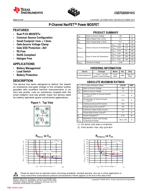
VDS = –10V, IDS = –1A
VDS = –10.25V, VGS = 0V
VDS = –10V, VGS = –4.5V, IDS = –1A, RG = 10Ω
IDS = –1A, VGS = 0V Vdd = –10.25V, IF = –1A, di/dt = 200A/μs Vdd = –10.25V, IF = –1A, di/dt = 200A/μs
td(on)
Turn On Delay Time
tr
Rise Time
td(off)
Turn Off Delay Time
tf
Fall Time
Diode Characteristics
VSD
Diode Forward Voltage
Qrr
Reverse Recovery Charge
trr
Reverse Recovery Time
TJ = 25°C
TJ = 125°C
1
2
3
4
5
-VGS − Gate to Source Voltage − V
6
G006
500 450 400 350 300 250 200 150 100
50 0 0
RD1D2(on) vs VGS
ID1D2 = -1A
TJ = 25°C
TJ = 125°C
1
RDS(on) Drain to Source On Resistance
RD1D2(on) Source to Drain On Resistance
gfs
Transconductance
IOS-MAT-0054_CNv5
参考
本技术规范中化学品要求和测试所引用的标准,如欧盟指令,都适用标准、指令的最新版本,除非 另有说明。
本资料仅供参考,英文版本 IOS-MAT-0054 具有最终法律效力。
1 of 23 2009-10-26 Elsa Hou 译稿
表2. 实木、木基材料和天然材料的要求
物质
要求
测试方法
文件
硼及其化合物
不允许使用硼及其化合物。
在实木(包括实木拼板)、 污染限值:硼及其化合物的迁移 天然纤维、胶合板、层压 值:30 mg 硼/kg 板/弯曲木中
如果木材有涂层,在 SD 测试前应去除涂层。
DIN 53160(用人工 合成汗液进行萃取, 16小时,23 °C), 然后依照EN ISO 11885(ICP/AES分 析)
IOS-MAT-0054 第五版译文
原版本代号:
审稿人:Jason Liu, Teresa Xu, Sebrina Chen
AA-92520-5 2009-10-09
化合物和化学物质:对儿童产品与玩具的附加要求
内容
本规范阐述了宜家对所有儿童产品(包括玩具)的化合物和化学物质的附加要求。
关于此规范
本规范的目的是确保儿童产品和玩具在儿童使用时是安全的,因为儿童更为敏感,并且接触产品的 方式与成人不同(如吮吸和咀嚼)。
染料
不允许使用。
在印刷或上色的纸/纸板中 污染限值:每种染料10 mg/kg
甲醛(50-00-0)
甲醛含量不可高于30mg/kg。 EN 71-11
文件 SD
SD
2.3 纺织品
表4.对纺织品的要求
RA2A23D25中文资料

crossing of the lineSolid State Relays Type SelectionSwitching mode Rated operational Rated operational Control Non-rep. Load voltagecurrentvoltage voltage type A: Zero switching23: 230VACrms 25: 2 x 25AACrms D: 4.5 - 32VDC23: 650V p M: Inductive40: 400VACrms 40: 2 x 40AACrms40: 850V p 48: 480VACrms 48: 1200V p 60: 600VACrms60: 1200V pSelection GuideRated operational Non-rep. voltage Control voltage Rated operational current voltage 2 x 25AACrms 2 x 40AACrms 230VACrms 650V p 4.5 - 32VDC RA2A23D25RA2A23D40RA2A23D25M RA2A23D40M 400VACrms 850V p 4.5 - 32VDC RA2A40D25RA2A40D40RA2A40D25M RA2A40D40M 480VACrms 1200V p 4.5 - 32VDC RA2A48D25RA2A48D40RA2A48D25M RA2A48D40M600VACrms1200V p4.5 - 32VDCRA2A60D25 RA2A60D40 RA2A60D25M RA2A60D40MIndustrial, 2-Pole ZS Type RA2Ademanding inductive loads.Input SpecificationsOutput SpecificationsGeneral SpecificationsFunctional Diagram DimensionsAll dimensions in mm0.680.560.440.320.190.07820.870.730.590.450.310.17721.100.940.780.620.450.29621.41 1.22 1.030.830.640.45521.8 1.6 1.36 1.130.900.67432.3 2.0 1.7 1.4 1.10.86353.0 2.6 2.2 1.9 1.5 1.1127443 2.6 2.0 1.52066543 2.4131312108756203040506070Heatsink Dimensions (load current versus ambient temperature)RA 2....25/25MT AAmbient temp. [°C]5045403530252015105Powerdissipation [W]Thermal resistance [K/W]Loadcurrent [A]1.110.940.780.620.460.29621.36 1.170.990.800.610.43541.68 1.47 1.25 1.030.810.60462.06 1.80 1.54 1.29 1.030.77392.5 2.2 1.87 1.56 1.250.94323.1 2.7 2.3 1.9 1.6 1.17264.0 3.5 3.0 2.5 2.0 1.5220654 3.5 2.8 2.11498764 3.3918161412974RA 2 (40)TAAmbient temp. [°C]8072645648403224168Powerdissipation [W] Thermal resistance [K/W]Loadcurrent [A]Carlo Gavazzi Heatsink Thermal ...for power(see Accessories)resistance... dissipation No heatsink required ---N/ARHS 300 5.00K/W > 0 W RHS 100 3.00K/W > 25 W RHS 45C 2.70K/W > 60 W RHS 45B 2.00K/W > 60 W RHS 90A 1.35K/W > 60 W RHS 45A plus fan 1.25K/W > 0 W RHS 45B plus fan 1.20K/W > 0 WRHS 112A 1.10K/W > 100 W RHS 3010.80K/W > 70 W RHS 90A plus fan 0.45K/W > 0 W RHS 112A plus fan 0.40K/W > 0 W RHS 301 plus fan 0.25K/W > 0 W Consult your distribution > 0.25K/W N/A Infinite heatsink - No solution ---N/AHeatsink SelectionRA 2....40MT AAmbient temp. [°C]100 9080706050403020105Powerdissipation [W]Thermal resistance [K/W]Loadcurrent [A]0.410.320.230.130.04-1080.550.440.340.230.130.02950.720.600.480.350.230.11820.950.800.660.520.370.23701.25 1.080.900.730.560.39581.7 1.5 1.25 1.040.830.61472.2 1.9 1.6 1.4 1.10.82363 2.7 2.3 1.9 1.5 1.1426544 2.9 2.3 1.817109765 3.68201715121074203040506070AccessoriesHeatsinksDIN rail adapter Varistors FusesFor further information refer to "General Accessories".InsulationNote: Add the currents of both poles and compare with datasheets for proper heatsink.Each pole can handle up to the maximum current specified. Example: Each pole of the RA2A23D25 can handle a maximum of 25 A.ApplicationsHeat flowHeatsink temperatureR th j-cR th c-sR th s-aJunction temperatureCasetemperatureAmbient temperatureThis relay is designed for use in applications in which it is exposed to high surge condi-tions. Care must be taken to ensure proper heatsinking when the relay is to be used at high sustained currents. Ade-quate electrical connection between relay terminals and cable must be ensured.Thermal characteristics The thermal design of Solid State Relays is very important.R th c-s = case to heatsink R th s-a = heatsink to ambientThermal resistance:R th j-c = junction to case It is essential that the user makes sure that cooling is ad-equate and that the maximum junction temperature of the relay is not exceeded.If the heatsink is placed in a small closed room, control panel or the like, the power dissipation can cause the ambient tem-perature to rise. The heatsink is to be calculated on the basis of the ambient temperature and the increase in temperature.Thermal SpecificationsApplicationsA single two pole relay in a three phase application. Star and Delta (Economy switch)A two pole relay and a single pole relay connected on a three phase application. Delta, star and star with a neu-tral point.。
ISO-75-2-2013-中文版

ISO-75-2-2013-中文版ISO 75-2: 2013塑料负荷变形温度的测定第2部分:塑料和硬橡胶1 范围ISO 75标准的本部分内容规定了三种使用不同恒定弯曲应力值测定塑料(包括填充塑料和以加工前长度可达7.5 mm纤维增强的塑料)和硬橡胶的负荷变形温度。
——使用1.80 MPa弯曲应力的A法;——使用0.45 MPa弯曲应力的B法;——使用8.00 MPa弯曲应力的C法。
测定负荷变形温度所使用的标准挠度Δs对应于ISO 75本部分所规定的弯曲应变增量Δε。
试样f在室温时由于承受负荷而产生的初始弯曲应变在ISO 75的本部分内容中既没有说明,也不能测量。
弯曲应变差值对初始弯曲应变的比率取决于受试材料的室温弹性模量。
因此,本方法仅适用于对室温弹性性能相似材料的负荷变形温度进行比较。
注1:本方法对无定形塑料比对部分结晶塑料有更好的再现性。
为得到可靠的试验结果,某些材料可能需要将试样进行退火处理。
如果采用了退火程序,通常导致其负荷变形温度增加(见6.6)。
注2:更多信息见ISO 75-1:2013第1章。
2 规范性引用文件以下文件的全部或部分内容被本标准引用,是使用本标准中不可缺少的部分。
对于更新过的文献(包括任何修订),其最新版适用于本标准。
ISO 75-1,塑料——负荷变形温度的测定——第1部分:通用试验方法ISO 293,塑料——热塑性材料压塑试样ISO 294-1,塑料——热塑性材料注塑试样——第1部分:一般原理及多用途试样和长条试样的制备ISO 2818,塑料——机械加工制备试样ISO 10724-1,塑料——热固性粉状模塑料注塑试样(PMCs)——第1部分:一般原理及多用途试样的制备ISO 20753,塑料——试样3 术语和定义ISO 75-1中规定的术语和定义适用于本部分。
注:按所选择的弯曲应力值(见第1章)的不同,负荷变形温度(见ISO 75-1:2013中的3.7定义)分别用Tf 0.45、Tf1.8或Tf8.0三种符号b:(10±0.2)mm;厚度h:(4±0.2)mm。
7525中文资料

TOSGAGE Series
X-ray Thickness Gage
General
The X-ray thickness gage is used to measure the thickness of a strip continuously without contacting that strip. This gage uses the fact that the amount of radiation that passes through the strip varies with the thickness of that strip. The TOSGAGE-7525 is a high quality thickness gage for cold rolling achieving outstanding safety, operability, accuracy and cost-performance developed over many years. It has the following features. • Noise immunity is improved by digitizing the signals between the measuring head and the equipment cabinet.
TOSGAGE -7525
• The operation-PC uses Windows® NT, and is a user-friendly PC. • A newly-developed X-ray generator is used, providing extremely accurate measurement results with a quick response time. The TOSGAGE-7525 focuses X-ray beams finely in the strip width direction to improve thickness resolution in the strip width direction, and making it suited to measuring the shape of the section of measured materials. The TOSGAGE-7525 can also be used as a AGC backup for when the fixed thickness gage (TOSGAGE-7521/7522) has failed.
DIN75220-1992中文版
共 10 页第 1 页1 适用范围和目的该方法有利于检测原来的安装位置和发动机类型中众多汽车构件的老化特性,2.9 试验室温度(即:室外温度)试验室温度就是那种由空气温度所规定的气温。
2.10 试验箱温度(即:室内温度)试验箱温度就是那种由空气温度所规定的气温。
假如试验箱需要室外温度,那么该试验箱温度就是就是测量值。
2.11 试样试样就是整车、标准部件、构件或者其中的断面等等。
2.12 试体试体就是在试验前、试验期间或者试验后为了评估而从试样中取出的材料试样。
2.13 负荷区 1负荷区1就是由于其安装位置应对构件施加强力负荷的乘员舱区域(例如:仪表板、衣帽架)。
2.14 负荷区 2负荷区2就是由于其安装位置应对构件施加极小负荷的乘员舱区域(例如:车门内饰、地毯)3 试验方法简述把整车或者外构件以适当的方法放入试验室。
而内构件则装配到安装位置并放入试验箱。
产生人工全照射的照射装置在7.2.3章所规定的其他气候参数下以规定的照度照射试样,试验结束后评估该整车或者相应的构件。
4 标法按本标准的老化试验标法汇编如下:- 标准号;- 按7.2章的试验方法简述示例 1按7.2.1章在室外条件(OUT)下的循环试验(Z)的标法:试验DIN 75 220 – Z – OUT示例 2按7.2.2章在室内条件(IN)、负荷区2、白昼潮湿气候(F)下的耐久试验(D)的标法:试验DIN 75 220 – D – IN2 – F5 设备和辅助方法5.1 测量装置所有下列所述的测量装置都必须适用于测量值的记录。
必须按照制造商的说明来标定这些测量装置;但是每年至少进行一次标定。
5.1.1 照射只允许使用这些测量装置,在这些测量装置中,制造商可通过温度变化过程和接收器的老化以及通过对所击中照射的cos-可靠评估来予以说明。
为了测量照度E(W/m2)和同时测量照射H(J/m2),可使用下列测量装置:a) 在光谱范围280 <λ< 3000 nm时用辐射强度计进行测量。
SM7523芯片2.5-12V、350mALED照明方案测试报告V1.0
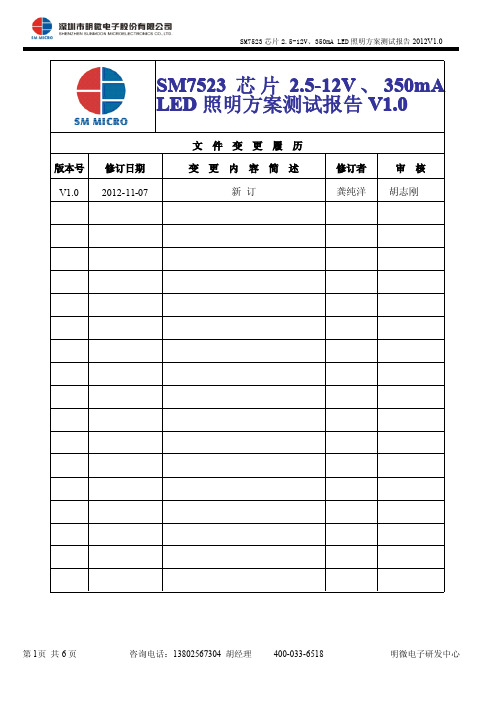
图 3:方案实物图(反面)
第 2页 共 6 页
咨询电话:13802567304 胡经理
400-033-6518
明微电子研发中心
SM7523 芯片 2.5-12V、350mA LED 照明方案测试报告 2012V1.0
三、方案 BOM 清单
位号 D1 D2 R1 R2 R3 R4 C1 C2 C3 C4 U1 材料名称 M7 SS115 2.4Ω 47K 1M 10K 4.7uF/400V 10uF 10 uF/25V 15pF SM7523 规格型号 DO-214 DO-214 1206 贴片电阻 0805 贴片电阻 1206 贴片电阻 0805 贴片电阻 铝电解电容φ8*12 0805 贴片电容 插件电解电容 0805 贴片电容 SOP8 用量(个) 1 1 1 1 1 1 1 1 1 1 1
240Vac 60.00 % 70.15 % 73.62 % 67.92 %
62.28 % 71.10 % 75.11 % 69.50 %
小结:在 180Vac-240Vac 电压输入范围内,系统平均效率>67% 。 2.3
空载功耗测试数据
180Vac 空载功耗 93mW
220Vac 100 mW
240Vac 123 mW
图 4:方案变压器参数
N2(8→5) Φ0.3 1 *1*2 7 T N 1(1→2) Φ0.1 7 *1*1 6 6 T
第 3页 共 6 页
咨询电话:13802567304 胡经理
400-033-6518
明微电子研发中心
SM7523 芯片 2.5-12V、350mA LED 照明方案测试报告 2012V1.0
第 6页 共 6 页
咨询电话:13802567304 胡经理
ST75256中文手册-自己翻译20171019
ST75256中文手册-自己翻译20171019ST752564 Level Gray Scale Dot Matrix LCD Controller/Driver Version 0.4目录1 简介 (4)2 产品特点 (4)3 PAD排列 (6)4 PAD中心坐标 (6)5 框图 (6)6 引脚介绍 (7)7 功能描述 (7)7.1 微处理器接口 (7)7.1.1 芯片选择输入 (7)7.1.2 并行/串行接口 (7)7.1.3 并行接口 (8)7.1.4 设置串行接口 (9)7.1.5 4线串行接口 (9)7.1.6 I2C接口 (9)7.2 数据传输 (9)7.3 显示数据存储器(DDRAM,即显存) (11)7.3.1 页地址电路 (13)7.3.2 列地址电路 (13)7.3.3 I/O缓冲电路 (13)7.3.4 显示数据锁存电路 (13)7.3.5 数据方向 (13)7.3.6 DDRAM映射到LCD驱动器输出 (15)7.3.7 局部显示(Partial Display) (17)7.3.8 区域滚动显示(Area Scroll Display) (17)7.4 LCD电源电路 (18)7.4.1 电源的外部组件 (18)7.4.2 调压电路 (19)9 命令 (21)9.1 指令表 (21)9.2 指令介绍 (25)9.2.1 扩展命令(Extension Command) (25)“扩展指令1”(“Extension Command 1”) (26) 9.2.2 显示开关 (26)9.2.3 反向显示 (26)9.2.4 所有像素开/关 (26)9.2.5 显示控制 (27)9.2.6 节电 (28)2 54 jackielau手动翻译9.2.7 设置页地址 (28)9.2.8 设置列地址 (29)9.2.9 数据扫描方向 (29)9.2.10 写数据 (31)9.2.11 读数据 (32)9.2.12 局部显示模式进入 (32)9.2.13 局部显示模式退出 (32)9.2.14读取/修改/写入模式进入 (33)9.2.15读取/修改/写入模式退出 (33)9.2.16 滚动区域 (34)9.2.17 滚动起始地址设置 (34)9.2.18 OSC ON (34)9.2.19 OSC OFF (34)9.2.20 电源控制 (34)9.2.21 设置Vop (35)9.2.22 Vop控制 (36)9.2.23 读寄存器模式 (36)9.2.24 NOP (36)9.2.25 读取状态 (37)9.2.26 数据格式选择 (37)9.2.27 显示模式 (38)9.2.8 图标控制 (38)“扩展指令2”(“Extension Command 2”) (38) 9.2.29 模拟电路设置 (38)9.2.30 升压倍率 (39)9.2.31 驱动选择 (39)9.2.32 大功率模式(High Power Mode) (40)9.2.33 自动读取控制 (40)9.2.34 OTP读写控制 (40)9.2.35 OTP控制退出 (40)3.2.36 OTP写入 (41)3.2.37 OTP读取 (41)3.2.38 OTP选择控制 (41)9.2.39 OTP编程设置 (41)9.2.40 帧率 (42)9.2.41 温度范围 (42)9.2.42 温度梯度补偿 (43)“扩展指令3”(“Extension Command 3”) (44) 9.2.43 设置ID (44)9.2.44 读取ID (44)10 操作流程 (45)10.1 上电 (45)10.2 掉电 (45)3 54 jackielau手动翻译10.3 OTP操作 (45)11 手触 (45)12 极限参数 (45)13 直流特性 (45)14 交流特性 (46)14.1 8080MCU接口的系统总线时序 (46)14.2 6800MCU接口的系统总线时序 (47)14.3 4线SPI MCU接口的系统总线时序 (48)14.4 串行接口(I2C接口) (49)14.5 复位时序 (50)15 应用注释 (51)15.1 应用电路 (51)15.1.1 并行8080接口 (51)15.1.2 并行6800接口 (52)15.1.3 4线SPI接口 (52)15.1.4 I2C接口 (53)16 主/从模式 (53)17 版本历史 (54)1 简介ST75256是一个用于4级灰度图形点阵液晶显示系统的驱动和控制器的大规模集成电路(LSI),包含256段和162个公用段。
3D7523G-0.5资料

RESET (RESB)
(Left high for normal operation)
1/f C 1 0 1 1 0 0 1 0
CLOCK (CIN)
tDS
DATA (DIN)
tDH T2H T2L T1H T1L
TRANSMIT (TXB) TRANSMIT (TX)
1
0
1
1
0
0
1
0
Figure 1: Timing Diagram (Encoder)
元器件交易网
3D7523
MONOLITHIC MANCHESTER ENCODER/DECODER (SERIES 3D7523)
FEATURES
• • • • • • • • • • All-silicon, low-power CMOS technology Encoder and decoder function independently Encoder has buffered clock output TTL/CMOS compatible inputs and outputs Vapor phase, IR and wave solderable Auto-insertable (DIP pkg.) Low ground bounce noise Maximum data rate: 50 MBaud Data rate range: ±15% Lock-in time: 1 bit For mechanical dimensions, click here. For package marking details, click here.
CIN CEN RX COUT DIN RESB GND
- 1、下载文档前请自行甄别文档内容的完整性,平台不提供额外的编辑、内容补充、找答案等附加服务。
- 2、"仅部分预览"的文档,不可在线预览部分如存在完整性等问题,可反馈申请退款(可完整预览的文档不适用该条件!)。
- 3、如文档侵犯您的权益,请联系客服反馈,我们会尽快为您处理(人工客服工作时间:9:00-18:30)。
PIN DESCRIPTIONS
The 3D7522 product family consists of monolithic CMOS Manchester RX Signal Input Decoders. The unit accepts at the RX input a bi-phase-level, CLK Signal Output (Clock) embedded-clock signal. In this encoding mode, a logic one is DATB Signal Output (Data) represented by a high-to-low transition within the bit cell, while a logic VDD +5 Volts zero is represented by a low-to-high transition. The recovered clock GND Ground and data signals are presented on CLK and DATB, respectively, with the data signal inverted. The operating baud rate (in MBaud) is specified by the dash number. The input baud rate may vary by as much as ±15% from the nominal device baud rate without compromising the integrity of the information received. Because the 3D7522 is not PLL-based, it does not require a long preamble in order to lock onto the received signal. Rather, the device requires at most one bit cell before the data presented at the output is valid. This is extremely useful in cases where the information arrives in bursts and the input is otherwise turned off. The all-CMOS 3D7522 integrated circuit has been designed as a reliable, economic alternative to hybrid TTL Manchester Decoders. It is TTL- and CMOS-compatible, capable of driving ten 74LS-type loads. It is offered in space saving surface mount 8-pin and 14-pin SOICs.
INPUT SIGNAL CHARACTERISTICS
Encoded data transmitted from a source arrives at its destination corrupted. Such corruption of the received data manifests itself as jitter and/or pulse width distortion at the input to the device. The instantaneous deviations from nominal Baud Rate and/or Pulse Width (high or low) adversely impact the data extraction and clock recovery function if their published limits are exceeded. See Table 4, Allowed Baud Rate/Duty Cycle. The 3D7522 Manchester Decoder Data Input is TTL compatible. The user should assure that the 1.5 volt TTL threshold is used when referring to all timing, especially the input pulse widths.
Doc #06002
10/31/2007
DATA DELAY DEVICES, INC.
3 Mt. Prospect Ave. Clifton, NJ 07013
1
元器件交易网
3D7522
APPLICATION NOTES
The 3D7522 Manchester Decoder samples the input at precise pre-selected intervals to retrieve the data and to recover the clock from the received data stream. Its architecture comprises finely tuned delay elements and proprietary circuitry which, in conjunction with other circuits, implement the data decoding and clock recovery function.
FREQUENCY (JITTER) ERRORS
The 3D7522 Manchester Decoder, being a selftimed device, is tolerant of frequency modulation (jitter) present in the input data stream, provided that the input data pulse width variations remain within the allowable ranges.
POWER SUPPLY AND TEMPERATURE CONSIDERATIONS
CMOS integrated circuitry is strongly dependent on power supply and temperature. The monolithic 3D7522 Manchester Decoder utilizes novel and innovative compensation circuitry to minimize timing variations induced by fluctuations in power supply and/or temperature. . 1
元器件交易网
3D7522
MONOLITHIC MANCHESTER DECODER (SERIES 3D7522)
FEATURES
• • • • • • • All-silicon, low-power CMOS technology TTL/CMOS compatible inputs and outputs Vapor phase, IR and wave solderable Low ground bounce noise Maximum data rate: 50 MBaud Data rate range: ±15% Lock-in time: 1 bit
DATB
3D7522Z-xxx
SOIC (.150)
3D7522D-xxx SOIC (.150)
For mechanical dimensions, click here. For package marking details, click here.
FUNCTIONAL DESCRIPTION
data 3 delay devices, inc.
PACKAGES
RX N/C N/C 1 2 3 4 5 6 7 14 13 12 11 10 9 8 N/C N/C N/C N/C N/C
VDD
RX CLK N/C GNDFra bibliotek1 2 3 4
8 7 6 5
VDD N/C N/C DATB
CLK N/C N/C GND
OUTPUT SIGNAL CHARACTERISTICS
The 3D7522 presents at its outputs the decoded data (inverted) and the recovered clock. The decoded data is valid at the rising edge of the clock. The clock recovery function operates in two modes dictated by the input data stream bit sequence. When a data bit is succeeded by its inverse, the clock recovery circuit is engaged and forces the clock output low for a time equal to one over twice the baud rate. Otherwise, the input is presented at the clock output unchanged, shifted in time. When engaged, the clock recovery circuit generates a low-going pulse of fixed width. Therefore, the clock duty cycle is strongly dependent on the baud rate, as this will affect the clock-high duration. The clock output falling edge is not operated on by the clock recovery circuitry. It, therefore, preserves more accurately the clock frequency information embedded in the transmitted data. Therefore, it can be used, if it is desired, to retrieve clock frequency information.
