SG250K3手册
涂装常用物流设备说明书
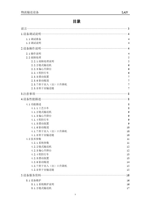
物流输送设备LAN目录前言 (3)1.设备调试说明 (4)1.1调试准备 (4)1.2调试说明 (4)2.设备操作说明 (4)2.1操作说明 (4)2.2故障处理 (5)2.2.1故障处理说明 (5)2.2.2链式输送机 (6)2.2.3偏心升降台 (6)2.2.4程控行车 (6)2.3.5摆动装置 (7)2.3.6驱动辊道 (7)2.3.7烘干室入(出)口升降机 (7)2.3.8烘干室输送链 (7)3.注意事项 (8)4.设备性能描述 (8)4.1功能描述 (8)4.1.1工艺小车 (8)4.1.2链式输送机 (9)4.1.3偏心升降台 (9)4.1.4程控行车 (9)4.1.5摆动装置 (9)4.1.6驱动辊道 (9)4.1.7烘干室入(出)口升降机 (10)4.1.8烘干室输送链 (10)4.2技术参数 (11)4.2.1系统参数 (11)4.2.2链式输送机 (12)4.2.3偏心升降台 (12)4.2.4程控行车 (13)4.2.5摆动装置 (13)4.2.6驱动辊道 (14)4.2.7烘干室入(出)口升降机 (15)4.2.8烘干室输送链 (15)5.设备服务资料 (16)5.1设备维护 (16)5.1.1系统维护说明 (16)5.1.2链式输送机 (17)1物流输送设备LAN5.1.3偏心升降台 (17)5.1.4程控行车 (18)5.1.5摆动装置 (18)5.1.6驱动辊道 (19)5.1.7烘干室入(出)口升降机 (19)5.1.8烘干室输送链 (20)5.2易损件清单 (21)5.3外购件清单 (23)5.3.1链式输送机 (23)5.3.2偏心升降台 (26)5.3.3程控行车 (26)5.3.4摆动装置 (26)5.3.5驱动辊道 (27)5.3.6烘干室入(出)口升降机 (28)5.3.7烘干室输送链 (29)5.4设备图纸清单 (30)6.设备验收证明 (33)2物流输送设备LAN 前言本说明书是针对PQ35涂装线物流输送设备的操作、维护及保养编写的,文中对物流输送系统的故障处理、设备性能、技术参数、设备维护作了详细的说明。
G.S. Blodgett 产品说明书:KLT、KPT、KLS 和 KPS 系列三脚锅

S00055 Rev D (10/15)
Your Service Agency’s Address:
Model Serial number Kettle installed by Installation checked by
IMPORTANT
NOTE: 60, 80 & 100 GALLON KETTLES ARE SUPPLIED WITH
2 REAR SUPPORT LEGS
SAFETY RELIEF VALVE
STRAINER &
L L
FOR OPTIONAL FAUCET COLD WATER/HOTWATER 3/8” [10mm] O.D. TUBING
OPERATION Operating Instructions. . . . . . . . . . . . . . . . . . . . . . . . . . . . . . . . . . . . . . . . . . . . . . . . . . . . . 8
MAINTENANCE Cleaning. . . . . . . . . . . . . . . . . . . . . . . . . . . . . . . . . . . . . . . . . . . . . . . . . . . . . . . . . . . . . . . . . .
[535] [460] [940] [885] [724] [558] [651] [305] [337] [432] [419] [1512]ห้องสมุดไป่ตู้
[391]
KLT-30DS 24 20 37 37.75 31.5 20.75 27.13 12.5 14.25 15 14.5 62.5 - 15.38
SG系列光伏并网逆变器选型手册
Skyworks Solutions Inc. 高性能陶瓷带通滤波器数据手册说明书

Introduction and Applications for Ceramic Band Pass FiltersDATA SHEETFeaturesGHigh Q ceramic G RuggedG Temperature compensated G Custom designsBenefitsGLow insertion loss G Small compact design G Frequency stability G MechanicalstabilityIntroductionTrans-Tech Inc.,a wholly-owned subsidiary of Skyworks Solutions Inc.,is a world-class supplier of high performance ceramic band pass filters.Specializing in band pass,notch and diplexing applications,Trans-Tech can cover a frequency range from 300MHz to 6000MHz with surface mount or connectorized devices.Utilizing state of the art assembly automation,Trans-Tech provides cost-effective solutions meeting high performance specifications.Trans-Tech surface mount PCB configured filters are designed to comply with “green”manufacturing initiatives eliminating heavy metal elements.This configuration is designed to comply with pending European regulations regarding the elimination of lead in electronic assemblies.Custom assemblies can be obtained with flat pack style SMT devices,through-hole or Sn/Pb coated PCB surface mount designs.Trans-Tech assembly methodology offers a wide array of designs,from 2mm x 2pole –8mm x 10pole band pass filters and diplexers,to advanced band stop (notch)designs and high-pass or low-pass filters.For typical applications and ranges of prod-ucts,refer to the Standard Filters/Duplexers listing included in this document.Detailed specifications,both mechanical andelectrical,are maintained for many popular designs on our Web site,or by contacting your local sales representative.The nature of applications utilizing a band pass filter,duplexer or notch filter,necessitates the close interaction of the customer and Trans-Tech application engineering.Our application engi-neers employ the latest in simulation and circuit analysis software with accurately defined design rules to provide rapid turnaround on new filter designs.With our experience and design aids,Trans-Tech can provide the necessary support for your application from prototype through production.In addition to the personal attention,Trans-Tech offers a computer-aideddesign tool,CRaFT,to assist engineers designing filters (the latest version can be downloaded from our Web site,.The strength of Trans-Tech designs begin with our ability to produce our own coaxial resonators from proprietary ceramic formulations.These resonators provide a high Q element that allows us to maintain our low filter insertion loss values.With numerous design package styles,Trans-Tech offers aggressive leadtimes on both prototype and volume applications.DATA SHEET •INTRODUCTION AND APPLICATIONS FOR CERAMIC BAND PASS FILTERSCenter frequency 300MHz to 6GHzStandard filter type Ceramic band pass,duplexer,notch,LPF Number of poles 2–10Resonator sizes 2,3,4,6,8and 12Bandwidth 1.0%–10%(May vary depending on resonator size,F O &εR )Insertion loss 1–4dB typical by design Attenuation Varies by number of poles Impedance 50or 75ΩVSWR2.0:1maximum Operating temperature range -40to +85°CMechanical packaging options PCB surface mount,thru-hole,&flat pack surface mount Power handling (continuous)1W typical*Figure 1.1Standard Capabilities**Contact Skyworks application engineering for assistance with any other requirement.Standard Filters/Duplexers*This list contains Trans-Tech most popular filter and diplexer designs.A variety of footprints and configurations are available for application-specific needs.Please contact the factory or your local representative with your specifications or for more informa-tion on any of these designs.Trans-Tech maintains a list of over 700active filters and diplexers.We welcome every opportunity to assist in the selection or creation of a filter or diplexer that will meet your specifications.Standard Filter Selection GuideTrans-Tech has a wide range of standard filters,as well as the capability to rapidly create new custom designs.Figure 1.1illus-trates our general capability for filters.If a desired requirement falls within the listed categories,Trans-Tech can easily offer a suitable design.Beyond this general list,Trans-Tech has a staff of experienced filter designers who can provide new custom and more technologically difficult filters.In addition,the CRaFT pro-gram functions as a useful tool when analyzing filter requirements.Trans-Tech welcomes the chance to review specifications and determine a design solution.Center FrequencyBandwidth Insertion LossPart Number Filter Type Size/Poles (MHz)(MHz)(dB)Package TT3P2-1068P0-3507Band Pass 3mm/2pole 1068350.7PCB SMT TT4P2-1013P2-2020Band Pass 4mm/2pole 1013202PCB SMT TT4P2-1082.5P2-0720Band Pass 4mm/2pole 1082.572PCB SMT TT4P2-1082P2-0620Band Pass 4mm/2pole 108262PCB SMT TT4P2-1090P2-0610Band Pass 4mm/2pole 109061PCB SMT TT4P3-1030P2-1535Band Pass 4mm/3pole 103015 3.5PCB SMT TT4P3-1067P2-4420Band Pass 4mm/3pole 1067442PCB SMT TT6P4-1080P4-7015Band Pass 6mm/4pole 108070 1.5PCB SMT TT6P4-1090P2-1036Band Pass6mm/4pole1090103.6PCB SMTCATVCenter FrequencyBandwidth Insertion LossPart Number Filter Type Size/Poles (MHz)(MHz)(dB)Package TT6P6-0750P0-5017Band Pass 6mm/4pole 75050 1.7PCB SMT TT6P5-0765P0-11225Band Pass 6mm/5pole 765112 2.5PCB SMT TT6P2-0770T-1215Band Pass 6mm/2pole 77012 1.5PCB SMT TT6P3-0770T-1225Band Pass 6mm/3pole 77012 2.5PCB SMT TT6P3-0770T-2020Band Pass6mm/3pole770202PCB SMTWCSDATA SHEET•INTRODUCTION AND APPLICATIONS FOR CERAMIC BAND PASS FILTERSMDSCenter Frequency Bandwidth Insertion Loss Part Number Filter Type Size/Poles(MHz)(MHz)(dB)PackageTT4P3-2120P2-6020Band Pass4mm/3pole2120602PCB SMTTT4P6-2122P0-2835Band Pass4mm/6pole212228 3.5PCB SMTTT6P4-2158P2-14220Band Pass4mm/4pole2158142PCB SMTTT6P6-2500P3-3635Band Pass6mm/6pole250036 3.5PCB SMTISMCenter Frequency Bandwidth Insertion Loss Part Number Filter Type Size/Poles(MHz)(MHz)(dB)PackageTT4P2-0915P2-2620Band Pass4mm/2pole915262PCB SMTTT6P2-0902F-2518Band Pass6mm/2pole90225 1.8PCB SMTTT6P2-0915T-2518Band Pass6mm/2pole91525 1.8PCB SMTTT6P3-0902T-2520Band Pass6mm/3pole902252PCB SMTTT6P3-0915T-2520Band Pass6mm/3pole915252PCB SMTTT6P3-0917F-1425Band Pass6mm/3pole91714 2.5PCB SMTTT3P3-2400P1-1030Band Pass3mm/3pole2400103PCB SMTTT3P3-2450P1-1445Band Pass3mm/3pole245014 4.5PCB SMTTT6P3-2467P0-3330Band Pass6mm/3pole2467333PCB SMTCellular/PCS/DCS/UMTSCenter Frequency Bandwidth Insertion Loss Part Number Filter Type Size/Poles(MHz)(MHz)(dB)PackageTT3P2-1880P0-6010Band Pass3mm/2pole1880601PCB SMTTT3P3-0881.5P2-2530Band Pass3mm/3pole881.5253PCB SMTTT3P3-1880P0-6022Band Pass3mm/3pole188060 2.2PCB SMTTT3P3-1960P0-6022Band Pass3mm/3pole196060 2.2PCB SMTTT3P3-1960P2-6030Band Pass3mm/3pole1960603PCB SMTTT3P4-0836.5P2-2525Band Pass3mm/4pole836.525 2.5PCB SMTTT3P4-0881.5P2-2525Band Pass3mm/4pole881.525 2.5PCB SMTTT3P4-1880P2-6020Band Pass3mm/4pole1880602PCB SMTTT3P4-1880P2-6030Band Pass3mm/4pole1880603PCB SMTTT4P3-0863P0-0585Band Pass4mm/3pole86358.5PCB SMTTT4P3-2180P1-2540Band Pass4mm/3pole2180254PCB SMTTT4P4-1880P0-6216Band Pass4mm/4pole188062 1.6PCB SMTTT4P4-1960P0-6216Band Pass4mm/4pole196062 1.6PCB SMTTT4P5-2240P2-1032Band Pass4mm/5pole224010 3.2PCB SMTTT4P6-0860.5P0-1937Band Pass4mm/6pole860.519 3.7PCB SMTTT6P3-0836T-2520Band Pass6mm/3pole836252PCB SMTTT6P3-0860P3-2020Band Pass6mm/3pole860202PCB SMTTT6P3-0860T-2020Band Pass6mm/3pole860202PCB SMTTT6P3-0881F-2520Band Pass6mm/3pole881252PCB SMTTT6P5-1960P0-6025Band Pass6mm/5pole196060 2.5PCB SMTTT6P5-2280P1-7032Band Pass6mm/5pole228070 3.2PCB SMTTT6P6-1900P3-8035Band Pass6mm/6pole190080 3.5PCB SMTTT6P3-2140P2-6011Band Pass6mm/3pole214060 1.1PCB SMTTT6P10-R1950-T2140Diplexer6mm/10pole1950--PCB SMTDATA SHEET•INTRODUCTION AND APPLICATIONS FOR CERAMIC BAND PASS FILTERSGPSCenter Frequency Bandwidth Insertion Loss Part Number Filter Type Size/Poles(MHz)(MHz)(dB)Package TT4P4-R1227.6-T1575.42Diplexer6mm/3pole1227.6--PCB SMT TT4P3-1227.6P1-2030Band Pass6mm/3pole1227.6203PCB SMT TT4P3-1575.42P2-2040Band Pass6mm/3pole1575.42204PCB SMT TT3P3-1227.6P1-1030Band Pass6mm/3pole1227.6103PCB SMT TT3P3-1575.42P2-1030Band Pass6mm/3pole1575.42103PCB SMTOtherCenter Frequency Bandwidth Insertion Loss Part Number Filter Type Size/Poles(MHz)(MHz)(dB)Package TT3P4-2513P2-5055Band Pass6mm/3pole251350 5.5PCB SMT TT3P5-3687P1-7466Band Pass6mm/3pole368774 6.6PCB SMT TT4P3-3417P2-0220Band Pass6mm/3pole341722PCB SMT TT4P5-1090P0-1050Band Pass6mm/3pole1090105PCB SMT TT6P5-0810P3-5030Band Pass6mm/3pole810503PCB SMT TT6P4-0509P7-0148Band Pass6mm/3pole5091 4.8PCB SMT TT4P4-1000P2-1030Band Pass6mm/3pole1000103PCB SMT TT6P3-0826.5P3-0520Band Pass6mm/3pole826.552PCB SMT TT6P3-0827P3-0620Band Pass6mm/3pole82562PCB SMT TT6P6-1000P5-8530Band Pass6mm/3pole1000853PCB SMT TT6P6-0545P6-3022Band Pass6mm/3pole54530 2.2PCB SMT TT4P3-3500P2-10020Band Pass6mm/3pole3500102PCB SMT TT6P6-0889P3-4029Band Pass6mm/3pole88940 2.9PCB SMT TT6P4-0722P4-4817Band Pass6mm/3pole72248 1.7PCB SMT TT3P3-1088P2-9015Band Pass6mm/3pole108890 1.5PCB SMT TT6P3-0740P3-2020Band Pass6mm/3pole740202PCB SMT TT6P5-1950P3-6040Band Pass6mm/3pole1950604PCB SMT TT3P4-0917P2-4524Band Pass6mm/3pole91745 2.4PCB SMT TT6P3-1090P2-1029Band Pass6mm/3pole109010 2.9PCB SMT TT6P4-0770P0-1240Band Pass6mm/3pole770124PCB SMT TT6P3-1030P2-1029Band Pass6mm/3pole103010 2.9PCB SMT TT6P5-0881.5P0-2530Band Pass6mm/3pole881.5253PCB SMT TT6P3-0730P3-1213Band Pass6mm/3pole73012 1.3PCB SMT TT6P3-0445.25T-0145Band Pass6mm/3pole445.251 4.5PCB SMT TT4P3-2400P1-20015Band Pass6mm/3pole240020 1.5PCB SMT TT6P3-1080P2-0650Band Pass6mm/3pole108065PCB SMT TT6P3-0745.3P3-1920Band Pass6mm/3pole745.3192PCB SMT TT6P4-0435P0-3019-NS Band Pass6mm/3pole43530 1.9PCB SMT TT3P4-0895.5P2-3926Band Pass6mm/3pole895.539 2.6PCB SMTDATA SHEET •INTRODUCTION AND APPLICATIONS FOR CERAMIC BAND PASS FILTERSAvailable PackagesTrans-Tech offers filters in a number of standard packages.In addition to SMT,Trans-Tech offers a flat-pack and through-hole configuration.Mechanical drawings are provided for most of our filters.In addition to our standard offering,Trans-Tech has the capability and experience to meet many unique footprint layouts and custom packages.For each of our 2to 6pole packages,Trans-Tech can offer pro-files ranging from 2mm to 6mm.2mm SMTTT2P2—P—TT2P3—P—TT2P4—P—TT2P5—P—TT2P6—P—SMT FilterLengthFilter Inches mm P10.43411P20.51213P30.59015P40.66917P50.74819P60.82721P70.90623P0CustomCustomDimension ‘L’will vary in length dependent upon filter’s frequency.DATA SHEET •INTRODUCTION AND APPLICATIONS FOR CERAMIC BAND PASS FILTERSTT3P2—P—3mmSMTTT3P3—P—TT3P4—P—TT3P5—P—TT3P6—P—Dimension ‘L’will vary in length dependent upon filter’s frequency.SMT Filter LengthFilter Inches mm P10.43411P20.51213P30.59015P40.66917P50.74819P60.82721P70.90623P0CustomCustomDATA SHEET •INTRODUCTION AND APPLICATIONS FOR CERAMIC BAND PASS FILTERSTT4P2—P—4mmSMTTT4P3—P—TT4P4—P—TT4P5—P—TT4P6—P—Dimension ‘L’will vary in length dependent upon filter’s frequency.SMT Filter LengthFilter Inches mm P10.43411P20.51213P30.59015P40.66917P50.74819P60.82721P70.90623P0CustomCustomDATA SHEET •INTRODUCTION AND APPLICATIONS FOR CERAMIC BAND PASS FILTERSTT6P2—P—6mmSMTTT6P3—P—TT6P4—P—TT6P5—P—TT6P6—P—Dimension ‘L’will vary in length dependent upon filter’s frequency.SMT Filter LengthFilter Inches mm P10.43411P20.51213P30.59015P40.66917P50.74819P60.82721P70.90623P0CustomCustomDATA SHEET •INTRODUCTION AND APPLICATIONS FOR CERAMIC BAND PASS FILTERS6mm Flat Pack (F)6mm Thru-Hole (T)TT6P2—FTT6P2—TTT6P3—TTT6P3—FDimension ‘L’will vary in length dependent upon filter’s frequency.DATA SHEET•INTRODUCTION AND APPLICATIONS FOR CERAMIC BAND PASS FILTERSCopyright©2006,2007,Trans-Tech Inc.,Inc.All Rights Reserved.Information in this document is provided in connection with Trans-Tech,Inc.("Trans-Tech"),a wholly-owned subsidiary of Skyworks Solutions,Inc.These materials,including the information contained herein,are provided by Trans-Tech as a service to its customers and may be used for informational purposes only by the customer.Trans-Tech assumes no responsibility for errorsor omissions in these materials or the information contained herein.Trans-Tech may change its documentation,products,services,specifications or product descriptions at any time,without notice.Trans-Tech makes no commitment to update the materials or information and shall have no responsibility whatsoever for conflicts,incompatibilities,or other difficulties arising fromany future changes.No license,whether express,implied,by estoppel or otherwise,is granted to any intellectual property rights by this document.Trans-Tech assumes no liability for any materials,products or information provided hereunder,including the sale,distribution,reproduction or use of Trans-Tech products,information or materials,except as may be provided in Trans-Tech Terms and Conditions of Sale.THE MATERIALS,PRODUCTS AND INFORMATION ARE PROVIDED"AS IS"WITHOUT WARRANTY OF ANY KIND,WHETHER EXPRESS,IMPLIED,STATUTORY,OR OTHERWISE,INCLUDING FITNESS FOR A PARTICULAR PURPOSE OR USE,MERCHANTABILITY,PERFORMANCE,QUALITY OR NON-INFRINGEMENT OF ANY INTELLECTUAL PROPERTY RIGHT;ALL SUCH WARRANTIES ARE HEREBY EXPRESSLY DISCLAIMED.TRANS-TECH DOES NOT WARRANT THE ACCURACY OR COMPLETENESS OF THE INFORMATION,TEXT,GRAPHICS OR OTHER ITEMS CONTAINED WITHIN THESE MATERIALS.TRANS-TECH SHALL NOT BE LIABLE FOR ANY DAMAGES,INCLUDING BUT NOT LIMITED TO ANY SPECIAL,INDIRECT,INCIDENTAL,STATUTORY,OR CONSEQUENTIAL DAMAGES,INCLUDING WITHOUT LIMITATION, LOST REVENUES OR LOST PROFITS THAT MAY RESULT FROM THE USE OF THE MATERIALS OR INFORMATION,WHETHER OR NOT THE RECIPIENT OF MATERIALS HAS BEEN ADVISED OF THE POSSIBILITY OF SUCH DAMAGE.Trans-Tech products are not intended for use in medical,lifesaving or life-sustaining applications,or other equipment in which the failure of the Trans-Tech products could lead to personal injury, death,physical or environmental damage.Trans-Tech customers using or selling Trans-Tech products for use in such applications do so at their own risk and agree to fully indemnify Trans-Tech for any damages resulting from such improper use or sale.Customers are responsible for their products and applications using Trans-Tech products,which may deviate from published specifications as a result of design defects,errors,or operation of products outside of published parameters or design specifications.Customers should include design and operating safeguards to minimize these and other risks.Trans-Tech assumes no liability for applications assistance,customer product design,or damage to any equipment resulting from the use of Trans-Tech products outside of stated published specifications or parameters.。
三菱k3g发动机维修手册说明书

SERVICE MANUAL三菱ディーゼルエンジンMITSUBISHI DIESEL ENGINE K3G MITSUBISHI HEAVY INDUSTRIES, LTD.No. 5-1, Marunouchi, 2-chome Chiyoda-ku, Tokyo JapanPhone: Tokyo (03) 212-3111 Telex: J22282, J22443 HISHIJU1988This manual is for engines with the combustion bowl on the top of the pistons.If your engine has flat top pistons or shallow pistons or double recessed top pistons, please contact us for the application information. This is critical for the operation of the engine type.This compiled Mitsubishi engine manual is complementary from:Worldwide Parts Source LLCPhone: +1 269 - 673 - 2313Email:***********************https://Mitsubishi K3G Cylinder H ead Gasket Installation Information with H ead Bolt Tor q ue V alues and Se q uence, W ith V alve Lash Settings .Mitsubishi K3G Cylinder H ead Gasket Installation Information with H ead Bolt Tor q ue V alues and Se q uence,W ith V alve Lash Settings .Courtesy of W orldwide Parts Source LLCSource for hard to find engine gasket sets, pistons and rings sets, and engine overhaul kits.Phone: 269 673 2313 email: Parts@W Worldwide Parts Source LLC - Source for hard to find gasket sets , engine overhaul kits and engine repair parts.Email:*************************************:*****************PhPhone: 269 673 2313 Fax: 269 673 7226Worldwide Parts Source LLC - Source for hard to find gasket sets , engine overhaul kits and engine repair parts.Email:*************************************:*****************PhPhone: 269 673 2313 Fax: 269 673 72260·02 SECTIONAL VIEWS OF ENGINE ®--t==+-*---=®@(!)Longitudinal Sectional View of K3 EngineQ) Water outlet fitting @) ® Thermostat @ Thermostat fitting @ @ Inlet valve @ ® Cooling fan Cl}) @ Water pump @ (J) Water pump pulley @ @ Piston @ ® Connecting rod @ Fan belt Crankshaft pulley Crankshaft Gear case Oil pan Oil screen Oil filler cap Rocker cover Rocker arm0·02 @ Rocker shaft @ Cylinder head @ Cylinder block @ Push rod @ Tappet @ Camshaft Rear plate @ Flywheel0·04 SPECIFICATIONSIITypeFiring orderGeneral Compression ratioCombustion chamberEngine weightCylinderPerformanceNumber of cylindersBore x Stroke (mm)Total displacementMax. horsepower (ps/ r pm)Max. torque (kgm/ r pm)No load max. speed (rpm)Fuel consumption (g/ p s hr)Stability Back and forth, right and left inclina-angle tion (Lower limit of oil level)Injection pumpNozzleFuel systemGovernorFuel-TypeLubricationOil filtersystemOil capacity : Standard type ( ! )Cooling Typesystem Coolant capacity ( Q,)---Starter motorElectricalAlternatorsystemBattery0·04K3G l.... �4-cy cle, water-cooled, vertical diesel engine1-3-218Direct injection134382 X 781.236 Liters I·---·-Specified in each separate specification18525° during continuous operation,30° during short-time (less than 30 minutes) operationBosh M typeHole typeCentrifugal flyweight typeDiesel fuelForced lubrication (trochoid pump)Filter paper (full flow type)Upper limit: 3, 0, Lower limit: I. 8 (except 0. 5 ! for oil filter)-·Pressurized, forced recirculation with radiator3.0 (except for radiator and hoses)-··12V-I. 6kW12V-35A or 12V-40A12V -60AH min.·-----9Worldwide Parts Source LLC Phone: 269 673 2313 Email: Parts@Worldwide Parts Source LLC Phone: 269 673 2313 Email: Parts@(3)Nozzle leak test•Using the nozzle tester, pressurize the nozzleand maintain to 200"-'2 IO kg/ c m 2• Check the nozzle tip for fuel leakage.•Tightening torque of nozzle retaining nut :3"-'4 kgm•Tightening torque to the cylinder head :2. 0"-'2, 5 kgmIll Compression Pressure TestI. Preparation of TestMake sure the following condition before testing, (I)Engine oil, air cleaner, starter and batteryare in good condition.(2)Engine should be warm (coolant temperature :above 50 ·c).2. Test(I)Move the control lever to the stop position.(2)Remove all glow plugs, Install the compressiongauge adaptor and gauge to the cylinder.(3)Crank the engine until the gauge reading stopsrising and read the gauge,(4)After measurement, remove the compressiongauge and adaptor and install the glow plugs and glow plug wires.•Glow plug tightening torque : I. 5"-'2, 0 kgm Compression Pressure MeasurementItem Engine speed Compression pressure Difference between cylinders -19-� � 0·05Standard value270 rpm 29 kg/cm 2 3 kg/ c m 2 max.Worldwide Parts Source LLC - Source for hard to find gasket sets , engine overhaul kits and engine repair parts. Email:*************************************:*****************Phone: 269 673 2313 Fax: 269 673 7226Worldwide Parts Source LLC - Source for hard to find gasket sets , engine overhaul kits and engine repair parts. Email:*************************************:*****************Phone: 269 673 2313 Fax: 269 673 7226Worldwide Parts Source LLC - Source for hard to find gasket sets , engine overhaul kits and engine repair parts.Email:*************************************:*****************Phone: 269 673 2313 Fax: 269 673 7226Ill Inspection .and RepairRepair or replace the parts if necessary.(I)Valve refacingIf the valve face is worn, reface the face witha valve refacer, However, if the margin ofthe valve face exceeds the service limit afterrefacing, replace the valve.Description Standard value Service limit Margine I.0o.5(2)Valve stem end refacingIf the valve stem end is worn or pitting, the end should be ground with the valve refacer oran oil-stone. However, if the margin aftersuch refacing exceeds the limitation, the valveshould be replaced.(3)Valve spring inspection Freelength Check the valve spring for cracks or damage.Measure the free length, tension and squareness of the valve spring,Description Standard value Service limit 43-1. 0(mm) 14±0. 7 (at 36mm)Load 29. 8 ± 2 (at 28mm)(kg) -15% Squareness 2' or less 3'Fatigueand damageValve and Valve Spring Inspection45°Valve Refacing-37-� � 1·04/Dent and/wear i-----uneven wearand damage Wear and----poor contact MarginWorldwide Parts Source LLC - Source for hard to find gasket sets , engine overhaul kits and engine repair parts.Email:*************************************:*****************Phone: 269 673 2313 Fax: 269 673 7226��1·05 CYLINDER HEADII Valve Guide ReplacementReplace the valve guide if it is worn or damaged.Remove the valve guide by pressing it from the upper side to the lower (seat) side with a press,Description Standard value Valve guide 12±0. 5 pressing height(A)II Valve Seat RefacingRefer or replace the valve seat it necessary,Description Standard Servicevalue limitSinkage of 0, 5±0. 35 I. 5valve (A)Valve Guide Pressing HeightValve Head DepthValve Seat WidthValve Seat Refacing -42-Valve SeatWidth" ,, ValveA sinkageWorldwide Parts Source LLC - Source for hard to find gasket sets , engine overhaul kits and engine repair parts.Email:*************************************:*****************Phone: 269 673 2313 Fax: 269 673 7226Worldwide Parts Source LLC - Source for hard to find gasket sets , engine overhaul kits and engine repair parts.Email:*************************************:*****************Phone: 269 673 2313 Fax: 269 673 7226Ill InspectionRepair or replace the parts if necessary.DescriptionFront journal 0. D,Center journal 0. D.Rear journal 0. D.Cam heightCheck gear forwear and damageValve camshaftStandardvalue45443435.72(base 0. D. + lift) Former* 34.69Servicelimit-1.0-1.0BendCheck end face forwear and damageCheck cam contactface for wearCheck cam lobe forwear, shaft for bend,and speedometerdrive gear for damage��1·08Pump camshaftDescription StandardvalueRear journal 0. D. 25'Coupling groove width 5Cam height 44(base 0. D. + lift)-53-Servicelimit-0.5-1.0。
斯塔克 SG2, SG3 喷枪 使用说明书

- For the application of architectural paints and coatings -The following Warnings are for the setup, use, grounding, maintenance and repair of this equipment. The exclamation point symbol alerts you to a general warning and hazard symbols refer to procedure-specific risks. Refer back to these Warnings. Additional, product-specific warnings may be found throughout the body of this manual where applicable.SKIN INJECTION HAZARDHigh-pressure fluid from gun, hose leaks, or ruptured components will pierce skin. This may look like just acut, but it is a serious injury that can result in amputation. Get immediate surgical treatment.•Do not point gun at anyone or at any part of the body.•Do not put your hand over the spray tip.•Do not stop or deflect leaks with your hand, body, glove, or rag.•Do not spray without tip guard and trigger guard installed.•Engage trigger lock when not spraying.•Follow Pressure Relief Procedure in this manual, when you stop spraying and before cleaning, checking, or ser-vicing equipment .FIRE AND EXPLOSION HAZARDFlammable fumes, such as solvent and paint fumes, in work area can ignite or explode. To help prevent fire and explosion:•Use equipment only in well ventilated area.•Eliminate all ignition sources; such as pilot lights, ciga-rettes, portable electric lamps, and plastic drop cloths (potential static arc).•Keep work area free of debris, including solvent, rags and gasoline.•Do not plug or unplug power cords, or turn power or light switches on or off when flammable fumes are present.•Ground all equipment in the work area. See Grounding instructions.•Use only grounded hoses.•Hold gun firmly to side of grounded pail when triggering into pail.•If there is static sparking or you feel a shock, stop oper-ation immediately. Do not use equipment until you identify and correct the problem.•Keep a working fire extinguisher in the work area.EQUIPMENT MISUSE HAZARDMisuse can cause death or serious injury.•Do not operate the unit when fatigued or under the influ-ence of drugs or alcohol.•Do not exceed the maximum working pressure or tem-perature rating of the lowest rated system component. See Technical Data in all equipment manuals.•Use fluids and solvents that are compatible with equip-ment wetted parts. See Technical Data in all equipment manuals. Read fluid and solvent manufacturer’s warn-ings. For complete information about your material, request MSDS forms from distributor or retailer.•Check equipment daily. Repair or replace worn or dam-aged parts immediately with genuine manufacturer’s replacement parts only.•Do not alter or modify equipment.•Use equipment only for its intended purpose. Call your distributor for information.•Route hoses and cables away from traffic areas, sharp edges, moving parts, and hot surfaces.•Do not kink or over bend hoses or use hoses to pull equipment.•Keep children and animals away from work area.•Comply with all applicable safety regulations.PRESSURIZED ALUMINUM PARTS HAZARD Do not use 1,1,1-trichloroethane, methylene chlo-ride, other halogenated hydrocarbon solvents or flu-ids containing such solvents in pressurized aluminumequipment. Such use can cause serious chemical reaction and equipment rupture, and result in death, serious injury, and property damage.PERSONAL PROTECTIVE EQUIPMENTYou must wear appropriate protective equipment when operating, servicing, or in the operating area of the equipment to help protect you from serious injury. This equipment includes but is not limited to:•Protective eyewear•Clothing and respirator as recommended by the fluid and solvent manufacturer •Gloves•Hearing protectionWARNINGS312830MI n s t r u c t i o n s /P a r t s2312830MPressure Relief ProcedureFollow this Pressure Relief Procedure whenever instructed to relieve pressure, stop spraying, check or service equipment, or install or clean spray tip.1.Turn OFF power and turn sprayer pressure control to low-est pressure setting.2.Hold gun against side of flushing pail. Trigger gun into pail to relieve pressure.If you suspect spray tip or hose is clogged or that pressure has not been fully relieved after following the steps above, VERY SLOWLY loosen tip guard retaining nut or hose end coupling to relieve pressure gradually, then loosen completely. Clear hose or tip obstruction.Gun Trigger LockTo prevent injury when the gun is not in use, always set the gun’s trigger lock if unit is being shut down or left unattended.SetupMake sure sprayer is turned off and unplugged from powersource. Refer to your sprayer instruction manual for priming and spray instructions.Connect Gun to Sprayer1.Attach supply hose to sprayer fluid outlet.2.Attach other end of supply hose to gun swivel (5). Use two wrenches (one on the swivel (5) and one on the hose), totighten all connections securely.3.Refer to sprayer instruction manual for priming instructions.Installing Tip (26) and Guard (25) on Gun1.If equipment has recently been operated, relieve pressure . Set trigger lock.ing a pencil or similar object, insert seal(24) into back of guard (25).3.Install guard (25) over end of gun (1).4.Insert tip (26) in guard (25). Tighten retaining nut.OperationSpraying1.Unlock trigger lock.2.Be sure the arrow shaped tip (26) faces forward (spray).3.Hold gun perpendicular and approximately 12-inches (30 cm) from surface. Move gun first, then pull gun trigger (3) to spray a test pattern.4.Slowly increase pump pressure until coverage is uniform and even (see sprayer instruction manual for additional information).Aligning Spray1.Relieve pressure . Set trigger lock.2.Loosen guard retaining nut.3.Align guard (25) horizontally tospray a horizontal pattern.4.Align guard (25)vertically to spray a vertical pattern.Clearing Clogs1.Relieve pressure . Set trigger lock.2.Rotate tip (26) 180°. Unlock trigger lock. Trigger gun into pail or onto ground to remove clog.3.Set trigger lock. Rotate tip (26) 180° back to spray position.CleanupFlush gun after each work shift and store in a dry location. Do not leave the gun or any parts in water or cleaning solvents.WARNINGWARNINGWARNINGTrigger LockedTrigger Unlocked(spray)ti11308aWARNINGWARNINGWARNING(4) Vertical(3) Horizontal ti11564a ti11563a312830M 3Parts1c *Kit 288817 repairs both series A and B guns.1a replaces these three components of series A.Ref.Part DescriptionQty.1288817KIT, repair, gun (includes 1a, 1b, 1c)11a SEAT, valve 11b NEEDLE, gun11c 131477NUT, lock13243639TRIGGER, repair kitincludes 10, 32, 334195495GUARD, trigger 15238817KIT, swivel1195384ADAPTER, gun inlet (SG2)16 288749FILTER, gun 1CAN085FILTER, gun 17 179733SEAL, sleeve 18195395CAP, end110115484PIN, actuator222113409RETAINER, guard 123195393HANDLE, gun (SG2)1195788HANDLE, gun (SG3, SG3-E)1195920HANDLE, gun (SG3-A)124115485O-RING12617R014HOUSING, fluid 132177538STUD, trigger 133131476NUT, lock, hex 1Replacement Warning labels, tags and cards are available at no cost.Keep these spare parts on hand to reduce down timeRef.Part Description Qty.Ref Part Description Qty 24243004Single seal TRU 1CAN004Single seal TRU1243281OneSeal ™, RAC 5 (5-pack)1246453OneSeal ™, RAC X (5-pack)117P501KIT, gasket, FFLP, LP (5-pack)125237859GUARD, TRU 1CAN001GUARD, TRU 1243161GUARD, RAC 51246215GUARD, RAC X and LP 226TRU515TIP, spray 515, TRU 1CAN515TIP, spray 515, TRU 1286515TIP, spray 515, RAC 51LTX515TIP, spray 515, RAC X 1TRU517TIP, spray 517, TRU 1CAN517TIP, spray 517, TRU 1262515TIP, spray 515, RAC 51LP519TIP, spray, 519, LP 1For complete warranty information contact your local Graco distributor, call Graco customer service:1-800-690-2894 or visit our website: .All written and visual data contained in this document reflects the latest product information available at the time of publication.Graco reserves the right to make changes at any time without notice.For patent information, see /patents.Original instructions. This manual contains English. MM 312830Graco Headquarters: MinneapolisInternational Offices: Belgium, China, Japan, KoreaGRACO INC. AND SUBSIDIARIES • P.O. BOX 1441 • MINNEAPOLIS MN 55440-1441 • USA Copyright 2008, Graco Inc. All Graco manufacturing locations are registered to ISO 9001. Revised M, August 2020MaintenanceBefore performing any maintenance on gun, read all warnings on frontcover of this manual and relieve pressure .Cleaning/Replacing Filter (6)1.Relieve pressure . Set trigger lock2.Disconnect fluid hose from gun at swivel (5).3.Disconnect trigger guard (4) from guard retainer (22).4.Unscrew handle (23) from gun (1).5.Remove filter (6) through top of handle (23).6.Clean filter (6). Use a soft brush to loosen and remove excess debris.7.Insert clean filter (6) into handle (23).8.Reattach handle (23) to gun (1). Tighten securely.9.Reconnect trigger guard (4) to guard retainer (22).Translated ManualsRepairReplacing Needle1.Relieve pressure . Set trigger lock.2.Remove tip (26) and guard (25) from gun (1).3.Disconnect fluid hose from gun at swivel (5).4.Squeeze trigger while unscrewing diffuser.5.Remove locknut and end cap.6.Tap out needle.e a soft brush to clean out internal passages of gun.8.Grease o-rings of new needle using a non-silicon grease.9.Guide new needle (15b) through front of gun .10.Install end cap and locknut, loosely.11.For needle housing (15a), apply medium strength (blue) threadsealant to threads.12.Squeeze trigger while installing needle housing. Torque to 26-32 ft-lb (35-43 N•m).13.Hold gun with nozzle facing up.14.Set trigger lock.15.Turn locknut (a) clockwise until you see and feel trigger (3) raise slightly.16.Turn locknut (a) 3/4 turn counter-clockwise.NOTE: When needle is properly adjusted, trigger will move freely.17.Connect fluid hose. Install tip (26) and guard (25).18.Prime sprayer. See sprayer instruction manual.19.Trigger gun into bucket until fluid flows from gun.20.Release trigger (3). Fluid flow should stop immediately.21.Set trigger lock.22.Aim gun into bucket. Trigger gun. No fluid should flow.23.If the gun fails tests, steps 19 and/or 21, relieve pressure and disconnect hose. Readjust needle. Repeat tests.Technical DataWARNINGFrench - 312831Estonian - 312845Spanish - 312832Latvian - 312846Dutch - 312833Lithuanian - 312847German - 312834Polish - 312848Italian - 312835Hungarian - 312849Turkish - 312836Czech - 312850Greek - 312837Slovakian - 312851Croatian - 312838Slovenian - 312852Portuguese - 312839Romanian - 312853Danish - 312840Bulgarian - 312854Finnish - 312841Chinese - 312855Swedish - 312842Japanese - 312856Norwegian - 312843Korean - 312857Russian - 312844WARNINGMaximum working pressure 3600 psi (248 bar, 24.8 MPa)Fluid orifice size 0.125 in. (3.18 mm)Weight (with tip and guard)22 oz. (630 g)InletMaximum material temperature 120 F (49 C)Wetted Parts Stainless steel, polyurethane, nylon, aluminum, tungsten carbide, brass *Noise Level: Sound power 87 dBaSound pressure 78 dBa*Measured at 3.1 ft (1m) while spraying water-based paint, specific gravity 1.36, through a 517 tip at 3000 psi (207 bar, 20.7 MPa) per ISO 3744Translated manuals can be requested through a distributor or at .。
K3系统销售指导手册
K3系统销售指导手册(第一稿)第一章本手册学习指南第二章K/3是什么第三章K/3系统定位与营销的关系第四章K/3系统及其竞争第五章K/3系统的销售策略第六章K/3系统的销售方法第七章K/3标准版、K/3基础版—制造业实施的几个问题第一章本手册学习指南K/3系统,经过开发者多年来夜以继日的辛勤努力,并经历在江淮动力、中山衡器等客户的锤炼,业已正式发版。
但如何做好K/3系统的销售,各分支机构的市场人员大多一时还没有掌握其规律,本手册的编写以期在这方面为有关人员有所帮助。
本手册所指的K/3系统产品是:K/3基础版—制造业、K/3基础版—商业贸易和K/3标准版。
金蝶公司的决策层已经指出:到2005年,金蝶公司要挤身世界管理软件前十强。
这一充满激情的决策为我们的前进道路指明了努力的方向,在此,让我们以一句话共勉:世上无难事,只要肯登攀。
第二章 K/3是什么一.K/3的寓意K:KINGDEE(金蝶)3:营建企业数字神经系统三步走的战略;解决企业供需链、价值链、决策链的管理问题以及金蝶公司的三核管理理论。
二.K/3是什么K/3是企业管理软件。
K/3基础版解决企业的供需链,既物流过程的管理和控制;K/3标准版以计划为核心,整体解决企业的物流、价值流、资金流。
K/3基础版为企业的数字化、信息化建设打下坚实的基础,包括管理水平和计算机技术应用的两个基础;K/3标准版在企业具备相当基础后,实现企业生产经营过程业务的全面整合,对人、财、物、产、供、销的各K/3系统销售指导手册项信息集成处理,迅速提高企业竞争的核心能力。
三.K/3系统的技术特点技术特点:大型数据库平台采用三层C/S结构,支持分布式和并发处理支持Internet/Intranet/Extrant 、电子商务、数据仓库组件程序设计,采用模板、向导、自定义等技术业务与财务完美结合,强大的核算管理和决策支持面向业务、面向职能的设计开放,系统具有高度的可扩充性四.K/3系统的体系结构见K/3系统宣传彩页五.K/3系统产品的模块组成见K/3系统产品宣传册第三章K/3系统定位与营销的关系一.K/3系统的营销定位第3页共13页二.K/3系统的定位与营销的关系从K/3系统的定位来看,有以下几个问题需要注意:1.K/3基础版—商业贸易是金蝶财务软件商业版的替代和增殖性产品,销售的目标客户及其服务与商业版财务软件大同小异。
K3车间技术支持手册
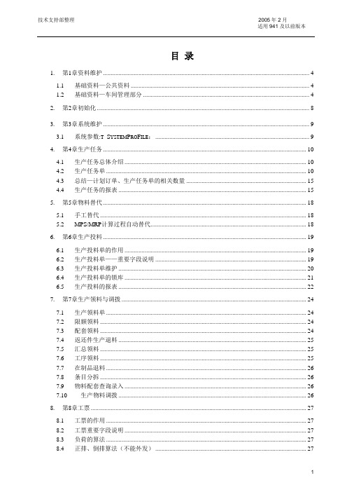
目录1. 第1章资料维护 (4)1.1 基础资料—公共资料 (4)1.2 基础资料—车间管理部分 (4)2. 第2章初始化 (8)3. 第3章系统维护 (9)3.1 系统参数:T_S YSTEM P RO F ILE: (9)4. 第4章生产任务 (10)4.1 生产任务总体介绍 (10)4.2 生产任务单 (10)4.3 总结—计划订单、生产任务单的相关数量 (15)4.4 生产任务的报表 (15)5. 第5章物料替代 (18)5.1 手工替代 (18)5.2 MPS/MRP计算过程自动替代 (18)6. 第6章生产投料 (19)6.1 生产投料单的作用 (19)6.2 生产投料单——重要字段说明 (19)6.3 生产投料单维护 (20)6.4 生产投料单的锁库 (21)6.5 生产投料的报表 (22)7. 第7章生产领料与调拨 (24)7.1 生产领料单 (24)7.2 限额领料 (24)7.3 配套领料 (24)7.4 返还件生产退料 (25)7.5 汇总领料 (25)7.6 工序领料 (25)7.7 在制品退料 (26)7.8 条目分拆 (26)7.9 物料配套查询录入 (26)7.10 生产物料调拨 (26)8. 第8章工票 (27)8.1 工票的作用 (27)8.2 工票重要字段说明 (27)8.3 负荷的算法 (27)8.4 正排、倒排算法(不能外发) (27)9.1 工序排程 (29)9.2 任务优先级设置 (30)10. 第10章工序汇报 (31)10.1 工序汇报维护 (31)10.2 工序的顺序 (31)10.3 工序的移转 (31)10.4 工序检验 (31)11. 第11章任务单汇报 (32)11.1 任务单汇报与工序汇报的区别 (32)11.2 保存任务单汇报 (32)12. 第12章生产物料报废 (33)12.1 生产物料报废 (33)12.2 物料报废单维护 (33)12.3 新增物料报废单 (33)12.4 删除物料报废单 (33)12.5 审核物料报废单 (33)12.6 反审核物料报废单 (33)12.7 注意事项 (33)13. 第13章重复生产 (34)13.1 重复生产总体介绍 (34)13.2 重复生产计划单 (34)13.3 计划订单、重复生产计划单、重复生产任务单的相关数量 (36)13.4 重复生产计划报表 (36)14. 第14章数据表 (38)14.1 资源T_R ESOURCE (39)14.2 工作中心T_W ORK C ENTER (39)14.3 主工厂日历T_W ORK C ALENDAR (39)14.4 多工厂日历T_M UTI W ORK C AL (39)14.5 工厂日历例外信息T_R ESOURCE E XP I NFO (40)14.6 生产类型T_W ORKTYPE (40)14.7 物料替代关系T_S UBS I TEM (40)14.8 工艺路线表头T_R OUTING (41)14.9 工艺路线表体T_R OUTING O PER (41)14.10 生产任务单ICMO (41)14.11 生产投料单PPB OM (43)14.12 生产投料单表体PPB OM E NTRY (44)14.13 物料报废单ICITEMSCRAP (45)14.14 物料报废单表体ICI TEM S CRAP E NTRY (45)14.15 工票SHW ORK B ILL (45)14.16 工票表体SHW ORK B ILL E NTRY (46)14.18 任务单汇报SHICMOR PT (48)1.第1章资料维护1.1基础资料—公共资料1.1.1部门:t_Department部门属性:FDProperty,部门属性定义在t_submessage表中;车间1070非车间1071部门属性对物流管理模块(包括成本管理)没有影响,仅对生产管理模块有影响,只有t_Department.FDProperty = 1070的部门才允许下挂工作中心。
K3操作手册解析
版本号:1.0密级:中级K/3项目操作手册信息科技有限公司2012年07月文档更新记录文档审核记录文档去向记录目录一、基础资料 (4)1、计量单位 (4)2、物料 (4)3、仓库 (8)4、仓位 (8)5、客户 (9)6、供应商: (10)7、部门和职员 (11)8、科目 (12)二、供应链业务 (14)1、采购管理 (14)2、销售管理 (17)3、仓库管理 (24)三、MPS及MRP计算 (26)1、 MPS计算 (26)2、 MRP计算 (32)四、MPS和MRP计划订单维护 (32)1、 MPS计划订单 (32)2、 MRP计划订单 (33)五、生产任务管理 (33)1、生产投料变更 (33)2、生产物料报废/补料 (34)3、任务单汇报/请检 (34)六、操作技巧 (35)一、基础资料1、计量单位新增计量单位“个”在K/3主界面点击【系统设置】——【基础资料】——【公共资料】——【计量单位】,点左边【计量单位】——【新增】打开计量单位组的新增界面,输入组名“个”,如图1.1.1图1.1.1然后点击【确定】,再点击右边空白后点击【新增】打开计量单位新增界面,输入代码“001”,名称“个”后点击确定。
图1.1.22、物料新增物料类别:一级类别产成品,二级类别 ODM,三级类别系列,四级类别炉头数1)、新增一级类别:【系统设置】——【基础资料】——【公共资料】——【物料】,点“新增”打开物料-新增界面,点【上级组】在代码输入‘C’,名称输入‘产成品’,如图1.2.1,然后【保存】;图1.2.1新增二级类别:点“C(产成品)”,点“新增”打开物料-新增界面,点【上级组】在代码输入‘C.D’,名称输入‘ODM’,如图1.2.2,然后【保存】;图1.2.2新增三级类别:点“D(ODM)”,点“新增”打开物料-新增界面,点【上级组】在代码输入‘C.D.81’,名称输入‘单炉、拉伸上、下盖低档炉’,如图1.2.3,然后【保存】;图1.2.3新增四级类别:点“81(单炉、拉伸上、下盖低档炉)”,点“新增”打开物料-新增界面,点【上级组】在代码输入‘C.D.81.1’,名称输入‘单炉头’,如图1.2.4,然后【保存】;图1.2.4新增物料:C.D.81.1.001,属性为配置类,使用的计量单位为台,放在二楼仓库-成品区,使用加权平均法计价,存货科目为1243,收入科目为5101成本科目为5401;在K/3主界面点击【系统设置】——【基础资料】——【公共资料】——【物料】,点【新增】打开物料新增界面,输入相应资料,如图1.2.5,图1.2.5在“物流资料”标签选择物料计价方法和相应的核算、收入、成本科目,如图1.2.6,图1.2.6在“计划资料”标签选择相应的计划策略、计划模式、订货策略,如图1.2.7,然后【保存】。
德国3k氯压机操作手册正文-2
5 压缩机装置的试车和操作电机和辅助单元的试车和操作,应遵从制造商的说明书。
5.1 初始试车的准备工作5.1.1松开压缩机的气体进出管线连接口法兰,检查一下管线在安装时确实没有应力。
5.1.2检查控制和安全系统。
5.1.3对控制阀进行功能性检查(阀门动作是否正常)。
5.1.4油冷却器泄漏检测。
5.1.5严格遵守下列要求,清洗整个润滑油系统:-清洗时采用的清洗油,应与操作时使用的润滑油型号相同。
-进行清洗之前,应拆除压缩机的调整轴承。
-将变速箱箱体上的供油管松开,用软管将供油管与回油管或油箱连接起来。
-用油泵将清洗油进行全量循环。
试车时,应由油冷却器的油侧腔体以及油过滤器排气。
-清洗油的油温应在40~50℃左右。
-两个油冷却器和油过滤器应轮流进行清洗。
-应将被堵塞的油过滤器的滤芯拿出来并清洗干净。
-整个清洗过程所需的时间,取决于过滤器收集的杂质的数量。
只有当经过2h的清洗,检查在过滤器内不存在杂质时才算完成了清洗工作。
-清洗工作结束后,重新安装上压缩机的轴承(操作轴承),把供油管与变速箱重新连接好。
5.1.6充装操作用润滑油。
5.1.7中间冷却器和机后冷却器的水侧的泄漏检测。
5.1.8关闭压缩机的进气阀、出气阀和放空阀。
向压缩机、冷却器及相关管线内充入空气或惰性气体,压力达到1~2 bar(操作压力)。
在所有的法兰连接处涂抹肥皂泡,进行气密检查。
5.1.9开启油泵,用限流孔板设定轴承油压力。
5.1.10脱开联轴器,检查电机的转向。
5.1.11设定轴向轴套的位置控制。
向压缩机进气口方向推压转子,使其就位于跟踪板内。
5.1.12设定轴套的震动控制。
5.2 初始试车5.2.1 机械运转测试检查电机转动方向后,重新将联轴器连接好。
然后按照5.3条款的步骤,启动运行30分钟,使用氮气介质,进行机械运转测试(轴承测试)。
停机后,应打开压缩机轴承进行目测检查。
5.2.2 操作测试压缩机轴承进行目测检查未发现异常后,重新将其安装上。
k3气动打标机的说明书资料

图 11
此时刻印针会立即对准到选择的标记的左上角位置,然后拖动处于选择状态
的标记,刻印针会始终跟随此标记运动,并且停留在标记的左上角位置,如果需
5.禁忌数:规定标记内容里不允许出现的数字。比如一些地域禁忌数字 “4”,那么可以在这里填入“4”,在运算时,标记内容将自动跳过数字“4”。比 如“123”在刻印完成后直接改变为“125”。
注意,无论标记内容的数值如何运算,都不会改变标记内容的字符长度,这 意味着,当流水号“AB9999”增加“1”会变为“AB0000”,而不是“AB10000”。
的布局模式下无效的。 2、扇形的调整的属性,如下图:
图 24 a.布局:可设置为字距调整,角度模式, b.方向:决定扇形排列时字符的顶端是朝向圆心或是背离圆心,不同方向的
效果如下图所示:
向外
向里
3.2.2 建立图形文件标记
用户可将自己制作的企业商标或其它标识图形导入到 K3 打标机系统中,然
后使用图形文件标记功能将其打印到工件上。K3 打标机系统支持 PLT 格式的矢
图9
设置流水号默认的参数设置,点击[设置流水号]按钮。此时我们刚才建立的 第二个标记变为红色,说明此标记已经被设置成了具有流水号功能的标记,如下 图:
图 10
当一个标记具有流水号功能时,每次刻印结束,都将按其规则自动累加,默 认情况下是“+1”,也就是说,当第一次刻印结束后,标记“123450”将变为 “123451”。
数用于指定标记在刻印区域中的位置。注意这里的 Z,Z 位置只在启用了 Z 轴升 降功能后有效,当您的刻印机具备升降功能时,Z 将可以设置标记刻印平面的高 度。 3.3 为标记设置编码
SG系列速度先锋说明书

SG 速度先锋电火花线切割控制柜使用说明书第一章速度先锋线切割控制柜1.概述:速度先锋型脉冲电源是我厂最新研制成功的新一代带MCU控制的高效率、高光洁度快速走丝线切割脉冲电源(具有自主知识产权),其主要特点:1.1新型大功率场效应管作功率管,强劲有力,切割效率高,切割光洁度高,有着良好的综合加工性能。
1.2独特的功能板接插式结构。
1.3可以切割800mm的大厚度工件,切割材料为模具钢和硬质合金等。
1.4具有良好的排屑功能,切割稳定,效率高,不易短路和断丝。
1.5采用220V(380V)交流电供电,可方便地与任何线切割机床配套。
1.6采用静电喷塑面机箱,外观精美,易清洁。
2.主要技术参数及工艺参数:2.1供电电源:AC220V(380V) 50Hz交流电2.2消耗功率:≤800W2.3空载电压:DC 70V~90V2.4带载电压:DC60V~80V2.5加工电流:0.5A~6A可调2.6最大短路电流:10A2.7粗糙度:1.6μm2.8稳定切割速度:60~80平方mm/min,最大加工效率>100平方mm/min2.9脉冲宽度:七档可调2.10脉冲间隔比(Toff/Ton):11档可调2.11功率7挡任选。
3.操作面板使用说明3.1共有7只功率选择数显.3.2脉冲宽度Ton的设定,Ton由脉冲宽度选择2-128.3.3脉冲间隔Toff设定:Toff由脉冲间隔选择开关决定,5-15对应的脉冲间隔与脉冲4.调试4.1要求用户通电之前打开机盖,检查各功能板有无松动,未检之前不得通电。
4.2确认率选择开关置于0位时,打开电源开关,这时,高频电压表应指示在60V~100V之间,~说明电源板工作正常。
如无电压,则检查机箱后面板的熔丝,如熔丝已断,应更换同规格的熔丝。
5.速度先锋型脉冲电源使用在机床品质完好,控制台运行正常的前提下,要发挥线切割机床的加工效率和加工质量,合理地选择脉冲电源的工艺参数是十分重要的。
史瓦格乐克焊接配件 超高纯度、专门清洁和工业焊接配件说明书

WELDFITTINGSWeld FittingsUltrahigh-Purity, Specially Cleaned, and Industrial■ 1/8 to 1 in. and 6 to 18 mm■ 316, 316L, 316L VAR, and 316L VIM-VAR stainless steel materials ■ Fittings for manual or automatic welding equipmentW E L D F I T T I N G SContentsMaterials of Construction . . . . . . . . . . . . . . . . . . . . . . . . 2Cleaning and Packaging . . . . . . . . . . . . . . . . . . . . . . . . .2Pressure Ratings Basis . . . . . . . . . . . . . . . . . . . . . . . . . . 3Micro-Fit ® (Miniature Tube Butt Weld) Fittings . . . . . . . 3Tube Butt Weld Fittings . . . . . . . . . . . . . . . . . . . . . . . . . 6Automatic Tube Butt Weld Fittings . . . . . . . . . . . . . . . . . 9Automatic Tube Socket Weld Fittings . . . . . . . . . . . . .12Tube Socket Weld Fittings . . . . . . . . . . . . . . . . . . . . . .13Pipe Socket Weld Fittings . . . . . . . . . . . . . . . . . . . . . . .15Pipe Butt Weld Fittings . . . . . . . . . . . . . . . . . . . . . . . . .16Swagelok ® Orbital Welding System . . . . . . . . . . . . . . .16➀ Includes straight configurations and all Micro-Fit weld fittings .➁ 20 % minimum elongation allowed .➂ Includes all elbows, crosses, and tees, excluding Micro-Fit weld fittings .Materials of ConstructionCleaning and PackagingStandardWeld fittings are cleaned in accordance with Swagelok Standard Cleaning and Packaging (SC-10) catalog, MS-06-62 .Special (SC‑11)Weld fittings are available cleaned and packaged inaccordance with Swagelok Special Cleaning and Packaging (SC-11) catalog, MS-06-63, to ensure compliance with product cleanliness requirements as stated in ASTM G93 Level C . To order, add ‑SC11 to the ordering number .Example: 6LV-4MW-6-2‑SC11Photovoltaic (SC‑06)Select weld fittings are available cleaned and packaged in accordance with Swagelok Photovoltaic Process Specification (SC-06) catalog, MS-06-64, to meet theprocess requirements of solar cell production . To order, add ‑SC06 to the ordering number .Example: 6LV-4MW-6-2‑SC06SC-06–cleaned weld fittings are available with controlled surface finishes and electropolishing . Wetted surfaces are finished to an average 5 µin . (0 .13 µm) R a . To order, add P6 to the ordering number .Example: 6LV-4MW-6-2P6Ultrahigh‑Purity (SC‑01)Select weld fittings are available with controlled surface finishes, electropolished, and specially cleaned . Wettedsurfaces are finished to an average 5 µin . (0 .13 µm) R a . Refer to Ultrahigh-Purity Process Specification (SC-01) catalog, MS-06-61, for additional information . To order, add P to the ordering number .Example: 6LV-4MW-6-2PCleaning Process AvailabilityOxygen Service HazardsFor more information about hazards and risks of oxygen-enriched systems, refer to Oxygen System Safety Technical Report catalog , MS-06-13 .Additional ConsiderationsConsult ASME Boiler and Pressure Vessel Code, ASME B31 .1,ASME B31 .3, or other applicable codes for information on weld setup, technique, and additional considerations for welded systems .The choice of fitting, pipe, and tubing material being welded is critical . Using the same materials will ensure the same coefficients of expansion and will reduce the possibility of poor welds, out-of-roundness, or dimensional changes that are detrimental to a good weld .Threaded End ConnectionsPipe threads are based on the requirements of ASME B1 .2 .0 .1 (NPT) and SAE AS71051 (ANPT) for tapered pipe threads .WELD FITTINGSCompact Design■ Accommodates tubing systems requiring miniaturization ■ Allows close component spacing■ Provides flow and service ratings equal to larger weldfittings .Ordering Information and Dimensions■ D imensions are for reference only and are subject tochange .■ See Cleaning and Packaging, page 2, to orderMicro-Fit weld fittings cleaned in accordance with Swagelok Special Cleaning and Packaging (SC-11)catalog , MS-06-63; Photovoltaic Process Specification (SC-06) catalog, MS-06-64; or Ultrahigh-Purity Process Specification (SC-01) catalog, MS-06-61 .Rounded body block helps prevent damage to other components during system fabrication or maintenance .Marking identifiesmanufacturer, material, and, when applicable, ultrahigh-purity cleaning .Material heat codeis roll stamped to ensure raw materialtraceability .Reducing UnionBB 1APressure Ratings BasisCatalog pressure ratings shown are for temperatures from–20 to 100°F (–28 to 37°C), which are based on an allowable stress value of 20 000 psi (1378 bar) in accordance with ASME B31 .3 and ASME B31 .1 for 316 stainless steel . 316L stainless steel material is controlled in accordance with Swagelok material specifications and possesses minimum room temperature tensile and yield strengths equivalent to 316 stainless steel .Pressure derating factors for applications at temperatures greater than 100°F (37°C) were determined from these pressure codes and are listed in the table at right .Elevated‑Temperature FactorsTo determine elevated-temperature pressure ratings in accordance with B31 .3 and B31 .1, multiply the pressureratings provided in the ordering number tables on the pages that follow by the factors in the table at right .Examples:A 1/4 in . 316L VIM-VAR reducing union has a pressure rating of 5100 psig (351 bar), as shown in the table below . To obtain the pressure rating at 400°F (204°C), multiply 5100 psig (351 bar) by 0 .77:5100 psig (351 bar) × 0 .77 = 3927 psig (270 bar)A 1/4 in . 316 SS tube socket weld union has a pressure rating of 10 700 psig (737 bar), as shown in the table on page 13 . To obtain the pressure rating at 400°F (204°C), multiply 10 700 psig (737 bar) by 0 .96:10 700 psig (737 bar) × 0 .96 = 10 272 psig (707 bar)Alternative elevated-temperature factors may be chosen from ASME B31 .3 or B31 .1 at the user’s discretion .Micro‑Fit (Miniature Tube Butt Weld) Fittings13 µm) R aW E L D F I T T I N G SExtended Leg 90° Union Elbow45° Union ElbowF flat90° Union ElbowMicro‑Fit (Miniature Tube Butt Weld) Fittings➀ 1/8 in . junction not radiused due to small bore sizeWELD FITTINGSUnion TeeExtended Run Leg Union TeeReducing TeeMicro‑Fit (Miniature Tube Butt Weld) FittingsW E L D F I T T I N G STube Butt Weld FittingsOrdering Information and Dimensions■ D imensions are for reference only and are subject tochange .■ See Cleaning and Packaging, page 2, to ordertube butt weld fittings cleaned in accordance with Swagelok Special Cleaning and Packaging (SC-11)catalog, MS-06-63; Photovoltaic Process Specification (SC-06) catalog, MS-06-64; or Ultrahigh-Purity Process Specification (SC-01) catalog, MS-06-61 .90° Union ElbowTribowThis unique design has weld ends in three planes at 90° to each other . It permits greater flexibility in designing systems, especially where space is limited .Micro‑Fit (Miniature Tube Butt Weld) FittingsUnion CrossPrecisely finished diameter matches tube diameter .Tube ends are machined witha square face and corners to enhance alignment and maintain tube wall uniformity .Standard surface finish is average 10 µin . (0 .25 µm) R a . Controlled surface finish is available for ultrahigh-puritysystems .WELD FITTINGSTube Butt Weld FittingsReducing UnionUnion TeeW E L D F I T T I N G SATW Weld RingATW weld rings are used with tube butt weld fittings . The ring helps align weld joints and adds material to the weld zone during manual or orbital welding .Reducing TeeUnion CrossTube Butt Weld FittingsWELD FITTINGSAutomatic Tube Butt Weld FittingsOrdering Information and Dimensions■ D imensions are for reference only and are subject tochange .■ See Cleaning and Packaging, page 2, to orderautomatic tube butt weld fittings cleaned in accordance with Swagelok Special Cleaning and Packaging (SC-11) catalog, MS-06-63; Photovoltaic Process Specification (SC-06) catalog, MS-06-64; or Ultrahigh-Purity Process Specification (SC-01) catalog, MS-06-61 .Locator UnionUnionReducing Union1Precisely finished diametermatches tube diameter .Integral filler ring aids in alignment .Standard surface finish is average 10 µin . (0 .25 µm) R a . Controlled surface finish is availablefor ultrahigh-puritysystems .W E L D F I T T I N G SSwagelok Tube Fitting to Automatic Tube Weld Connector90° Union ElbowUnion TeeAutomatic Tube Butt Weld FittingsWeld Fittings—Ultrahigh-Purity, Specially Cleaned, and Industrial 11WELDFITTINGSReducing TeeKBF flatBD 1TxTx 1Wall Thickness Ordering NumberDimensions, 0 .035316L-6-ATW-3-6-4Manifold TeeReducing TeeAutomatic Tube Butt Weld Fittings12 Weld, VCR, VCO, Pipe, and Vacuum FittingsW E L D F I T T I N G SUnion CrossUnion TeeBF flatDAutomatic Tube Socket Weld FittingsOrdering Information and Dimensions■ D imensions are for reference only and are subject tochange .■ See Cleaning and Packaging, page 2, to orderautomatic tube socket weld fittings cleaned in accordance with Swagelok Special Cleaning and Packaging (SC-11), MS-06-63 .Thin wall reducesweld heat input .Precise machining of socket ensures proper tube fit .UnionATxEDAutomatic Tube Butt Weld FittingsWeld Fittings—Ultrahigh-Purity, Specially Cleaned, and Industrial 13WELD FITTINGSPrecise machining of socket ensures proper tube fit .Tube Socket Weld FittingsOrdering Information and Dimensions■ D imensions are for reference only and are subject tochange .■ See Cleaning and Packaging, page 2, to orderautomatic tube socket weld fittings cleaned in accordancewith Swagelok Special Cleaning and Packaging (SC-11), MS-06-63 .UnionAEDDMale ConnectorFemale Connector14 Weld, VCR, VCO, Pipe, and Vacuum FittingsW E L D F I T T I N G SE90° Union Elbow90° Male Elbow90° Female ElbowUnion TeeDDTube Socket Weld FittingsWeld Fittings—Ultrahigh-Purity, Specially Cleaned, and Industrial 15WELDFITTINGS UnionPipe Socket Weld FittingsOrdering Information and Dimensions■ D imensions are for reference only and are subject tochange .■ See Cleaning and Packaging, page 2, to order pipesocket weld fittings cleaned in accordance with SwagelokSpecial Cleaning and Packaging (SC-11), MS-06-63 .Union CrossFDTube Butt Weld toTube Socket WeldDTube Socket Weld FittingsQuality machining of allsurfaces ensuresconsistent welding to pipe .Heavy wall, plus strengthof material, ensures longlife in severe serviceapplications .Socket depth equals orexceeds requirements ofASME B16 .11 and ensuresproper pipe support .16 Weld, VCR, VCO, Pipe, and Vacuum FittingsW E L D F I T T I N G SMS-01-149, RevO, August 2019Pipe Butt Weld FittingsOrdering Information and Dimensions■ D imensions are for reference only and are subject tochange .■ See Cleaning and Packaging, page 2, to order pipebutt weld fittings cleaned in accordance with Swagelok Special Cleaning and Packaging (SC-11) catalog, MS-06-63 .Male weld end can be butt or socket welded .37 1/2° chamfer ensuresproper weld(not included on 1/4 in . size) .Tube Socket Weld to Pipe Butt WeldTxSwagelok Orbital Welding SystemRefer to Welding System M200 Power Supply catalog, MS-02-342, for additional information .IntroductionSince 1947, Swagelok has designed, developed, and manufactured high-quality, general-purpose and specialty fluid system products to meet the evolving needs of global industries. Our focus is on understanding our customers’ needs, finding timely solutions, and adding value with our products and services.We are pleased to provide this global edition of the book-bound Swagelok Product Catalog, which compiles more than 100 separate product catalogs, technical bulletins, and reference documents into one convenient, easy-to-use volume. Each product catalog is up to date at the time of printing, with its revision number shown on the last page of the individual catalog. Subsequent revisions will supersede the printed version and will be posted on the Swagelok website and in the Swagelok electronic Desktop Technical Reference (eDTR) tool.For more information, visit your Swagelok website or contact your authorized Swagelok sales and service representative.Safe Product SelectionWhen selecting a product, the total system design must be considered to ensure safe, trouble-free performance. Function, material compatibility, adequate ratings,proper installation, operation, and maintenance are the responsibilities of the system designer and user.Warranty InformationSwagelok products are backed by The Swagelok Limited Life-time Warranty. For a copy, visit or contact your authorized Swagelok representative.Not all trademarks listed below apply to this catalog. Swagelok, Cajon, Ferrule-Pak, Goop, Hinging-Colleting,IGC, Kenmac, Micro-Fit, Nupro, Snoop, Sno-Trik, SWAK, VCO, VCR, Ultra-Torr, Whitey—TM Swagelok Company 15-7 PH—TM AK Steel Corp.AccuTrak, Beacon, Westlock—TM Tyco International Services Aflas—TM Asahi Glass Co., Ltd.ASCO, El-O-Matic—TM Emerson AutoCAD—TM Autodesk, Inc.CSA—TM Canadian Standards AssociationCrastin, DuPont, Kalrez, Krytox, Teflon, Viton—TM E.I. duPont Nemours and Company DeviceNet—TM ODVADyneon, Elgiloy, TFM—TM Dyneon Elgiloy—TM Elgiloy Specialty Metals FM—TM FM GlobalGrafoil—TM GrafTech International Holdings, Inc.Honeywell, MICRO SWITCH—TM Honeywell MAC—TM MAC ValvesMicrosoft, Windows—TM Microsoft Corp.NACE—TM NACE InternationalPH 15-7 Mo, 17-7 PH—TM AK Steel Corp picofast—Hans Turck KGPillar—TM Nippon Pillar Packing Company, Ltd.Raychem—TM Tyco Electronics Corp.Sandvik, SAF 2507—TM Sandvik AB Simriz—TM Freudenberg-NOKSolidWorks—TM SolidWorks Corporation UL—Underwriters Laboratories Inc.Xylan—TM Whitford Corporation© 2021 Swagelok Company。
GWJ3-GXT250输送线设备使用说明书

GWJ3-GXT250输送线设备使用说明书一、系统简介:本工程采用GWJ3-GXT250积放输送机系统,本形式积放系统能满足各个工艺要求而实现工件储存、分支、合流等.输送系统技术参数:1.主要技术参数(1)被输送工件单件最大重量:〈400kg(2)被输送工件最大外形尺寸:L3800mm ×W2000 mm×H2000 mm。
(3)输送线生产节拍:6min。
(4)输送机运行速度:10.0~12.0米/分(标准速度:?M/min)。
(5)输送机牵引链条计算长度约:134米(以双方确认的平面布置图为准)。
(6)输送机牵引链条结合节距:t =250mm,推钩间距:T=1500mm。
(7)积放区车组、工件积放间距:4455 mm。
输送机运行说明:1.本输送装置为工位全部为定点停止操作。
2.上件放行车组运行至喷漆房前停止器,等待前工位操作完毕。
工件运行至喷粉房内,通过停止器实现人工定点旋转喷涂。
3.车组快速进入固化室,停止5个节拍(5组车)。
最后出固化室至冷却工位(3工位),再运行至上下件区。
二、输送设备介绍与维护保养1.直线驱动装置:本积放悬挂输送机的驱动装置是整个输送机系统的动力源。
由机架、专用电机减速机、驱动链条、驱动主从动轮系、过载保护装置等组成。
具有机械过载断电保护、电流过热集电器双重保护,牢固的机架保证驱动站运行平稳,可调整的张紧轮及链条支撑机构使驱动链条处于张紧状态。
驱动装置中的驱动链条与牵引链条采用“轴承顶轴承”方式,实现“零”摩擦啮合传递扭矩。
驱动输出轴配有限扭器,防止卡位,过载等故障造成的不便。
开关保护安置在电机输出轴端,与电控系统配合完成故障保护作用。
表1表2 驱动装置故障及维修方法2.牵引链条GXT250链条为GX250型轻型链,经热处理,强度达到国家标准要求。
技术参数如下表(1).链条张力,(2)链条运行速度,(3)张紧装置的张力,(4)润滑,(5)系统中弯轨的数量。
K3工业物流应用指南(doc 48页)
K3工业物流应用指南(doc 48页)K3工业物流应用指南目录第一章基础资料 (3)第一节基础资料—公共资料 (3)第二节基础资料—工业物流部分 (12)第二章系统设置 (13)第三章初始化 (14)第四章业务流程 (16)第一节采购业务流程 (16)第二节销售业务流程 (22)第三节仓存业务流程 (25)第五章存货核算 (28)第一节核算系统应用流程 (28)第二节入库核算 (28)第三节出库核算 (28)第四节金额调整 (36)第六章特殊业务处理 (38)第七章物流与总帐对帐 (40)第八章生成凭证 (41)第九章结帐 (42)第十章Q & A (43)第一章基础资料基础资料是K3各个系统的公用资料,因此设置基础资料最重要的是要有“全局性”的思维。
尤其是分步实施情况下,最先上财务系统,不能仅着眼于财务系统,还要考虑到当前的设置对日后上业务系统所产生的影响。
第一节基础资料—公共资料一、会计科目1. 科目设置—科目结构设置会计科目时,必须考虑业务系统向总帐传递凭证的问题,否则会导致业务系统无法向总帐传递凭证。
2. 科目模板基础资料的科目可以从模板引入,模板放在在中间层的KDCOM下和客户端的安装目录下ACCOUNT.MDB文件中。
二、计量单位1. 双计量单位的应用例如:网线在采购时是按“箱”为单位采购的,而在使用时是按“米”为单位计量的;油漆在采购时候是按“桶”采购的,在使用时按“升”计量。
这种情况就要使用双计量单位:“系统参数设置==》工业整体选项==》使用双计量单位”。
一旦使用双计量单位,新增物料允许为指定“基本计量单位”和“常用计量单位”,物流单据和物流报表也按双计量单位显示。
K3工业版目前支持双计量单位,但是不支持多计量单位,在所有物流报表中,对于同一个物料,只能按基本和常用计量单位显示。
一个计量单位组中可以有多个计量单位,但只能且必须有一个计量单位是“默认”的计量单位。
一个物料的基本计量单位只能是“默认”的计量单位,一个物料的常用单位与基本单位必须在同一组内。
施道克给煤机学习教程

键盘
•用于输入指令
显示屏
•显示给煤机状态参数
We make processes work
电气元件图片 CPU板 电源板
We make processes work
操作面板
We make processes work
称重传感器、跑偏开关
皮带上有煤开关
We make processes work
We make processes work
2.硬件新特征
•DT-9为模块式设计(CPU板、 电源板等为一整体),包含了 两块主要控制板,每块控制板 都配置32位ARM中央处理器 •其中ARM9处理器用于逻辑计 算及处理参数等等,ARM7处理 器用于信号处理,增加了性能 稳定性 •I/O装置体积更小,不易受水 受潮及受粉尘。且更要的是所 有I/O接口可编程且可增加, 维护更方便,使用寿命更长 •增加了蓝牙接口 •支持最新各种现场总线 •增加了三个通信网口 •增加清扫链综合控制 •可存储200多条历史错误 •支持多种语音 •不断升级的操作系统 •远程诊断系统 •可编程plc程序
堵煤开关
出口温度计
We make processes work
给煤机本体
We make processes work
3.给煤机标定
在什么情况下标定? 首次启动后、运行第一个月后标定一次,此后每六个月标定一次, 调整称重辊或更换皮带、CPU板、称重传感器模块、微处理机程 序芯片时要进行标定。 了解上面的信息后,我们就开始标定 准备标定工具
We make processes work
可编程I/O接口工作状态显示
输入/输出可以随意定义 占用体积小,防尘效果好 指示灯颜色不同,含义不 同 抗电磁干扰强
