Tuning ASDA Series Servo Systems
台达运动控制应用例

台达运动控制应用例目录第1章单轴运动.........................................................................1-11.1原点回归模式...................................................................1-11.2自行规划多段变速度...........................................................1-81.3台达ASDA伺服简单定位展示系统........................................1-161.4手摇轮跟随模式(一)......................................................1-231.5手摇轮跟随模式(二)......................................................1-291.6手摇轮跟随模式(三)......................................................1-35第2章电子凸轮.........................................................................2-12.1电子凸轮(一)–周期性单轴凸轮...........................................2-12.2电子凸轮(二)-非周期性单轴凸轮.......................................2-122.3电子凸轮(三)-多轴凸轮.....................................................2-252.4绕线机应用....................................................................2-322.5电子凸轮应用–旋切控制....................................................2-412.6电子凸轮应用–追剪控制(Fly saw)......................................2-53第3章G-Code应用...................................................................3-13.1G–Code应用-三轴同动绘出Delta LOGO...............................3-13.2M Code应用...................................................................3-63.3GNC载应用-使用PMSoft汇入G-Code.................................3-103.4GNC应用-PMGDL软件下载(一般模式)..............................3-143.5GNC应用-PMGDL软件下载(DNC模式).............................3-223.6GNC应用-使用D Register转G码 ASCII格式下载..................3-283.7GNC应用-使用HMI配方方式透过 USB Disk下载...................3-383.8点胶模式.......................................................................3-49第4章其它应用.........................................................................4-14.1中断应用.........................................................................4-14.2计数器应用......................................................................4-64.3定时器应用....................................................................4-134.4以20PM作为从机应用.....................................................4-16i4.5PWM应用-水闸门控制程序................................................4-194.6高速比较应用.................................................................4-224.7高速捕捉应用.................................................................4-284.8制袋机应用-单段速外部触发模式........................................4-334.9PID应用......................................................................4-38 ii目录1.1 原点回归模式1.2 自行规划多段变速度1.3 台达ASDA伺服简单定位展示系统1.4 手摇轮跟随模式(一)1.5 手摇轮跟随模式(二)1.6 手摇轮跟随模式(三)1-1第1章 单轴运动1-1 1.1 原点回归模式20PM 位置控制与伺服驱动系统系统架构图【范例说明】1. 启动原点回归模式时,不同的启动位置其行走的路径也不同,以原点回归方向正转为例,其行走路径如下图所示:2. 20PM 的原点回归模式的设定参数D1816+80*N( N=0~2 )如以下所示:原点回归方向:原点回归方向可分为正转和反转。
拓斯达 辅机系统 高端智能装备产品说明书
作为中国整厂自动化第一品牌,拓斯达专注于高端智能装备,主张 的品牌价值,即随着技术不断进步与突破,用智能系统替代人工,开拓可替代的应用领域,推动产业进步助力企业发展,同时把制造业从劳动密集型带入完全的自动化,回归到自然,人性,和谐的状态。
新出现的文明与传统的旧工业文明有许多矛盾之处:它既有高度的科学技术,同时又是反工业化的。
As the top brand of complete factory automation in China, TOPSTAR focuses on high-end innovative equipment, proposes the brand value of. We initiate to replacelabor with intelligent systems, expand replaceable application areas and promote industrial progress to help enterprise developing, transform labor intensive type to full automation and return to a natural, human-oriented and harmonious status.Much in this emerging civilization contradicts the old traditional industrial civilization. It is, at one and the same time, highly technological and anti-industrial.摘自《第三次浪潮》——阿尔文·托夫勒from The Third Wave,Alvin Toffler企业简介Guangdong Topstar Technology Co., Ltd.(SZ.300607)is a National High-Tech Enterprise, focusing on the development of industrial robots, manufacturing and sales, dedicated to systems integration, products manufacturing and software development--three in one integration of industrial robot ecosystems and overall automation solution.Since the establishment in 2007, adhering to the brand advocate "Let Industrial Civilization Return To The Natural Beauty” and the core value "one year investment return for the automation solution", the business has maintained a rapid growth. In 2015, Topstar was named “China Industrial Automation Leading Enterprise” by the State Ministry of Information Industry Development Institute. We have served about 4000 customers in domestic and oversea market, including well-known companies from Global 500. Now our sales and service network are all over the country in China and the products have been exported to more than 30 countries in Asia, America, Europe, Africa, etc.In 2014, we were ranked on the 30th as "Potential 100 Non-Listed Chinese Enterprises" by Forbes. In 2015, we were named "China's Most Potential Enterprise" by Ernst & Young with Fudan University, at the same time won the Guangdong Provincial-level Enterprise Technical Center, the Rapid Growth of Small&Medium Enterprises of Guangdong Province, and as the only one robot enterprise selected in Guangdong Province Manufacturing 500, honored “2014 and 2015Annual Golden Globe” by GG Robots, etc. In 2016, was assessed as the first batch of robot key enterprises in Guangdong Province. Our enterprise is highly appreciated by national ministries , provincial and municipal leaders.At present, our shareholders include China Huarong, top PE Shenzhen Fortune Capital, Industrial Securities and Dongguan Sangem Group.Topstar has recruited top R&D experts from Canada, Korea and Taiwan, and carried out long-term research cooperation with Tsinghua University, Huazhong University of Science and Technology, South China University of Technology, Dongguan Institute of Technology and other research institutions and well-known colleges. We have achieved 100 national patents and 10 software copyrights.Three kinds of Robots with independent intellectual property were named Guangdong Provincial Famous Brand and five kinds of machines were named Guangdong High-Tech Products. Many machines have been certified by CE.Company profile广东拓斯达科技股份有限公司(SZ.300607)是国家级高新技术企业,专注于工业机器人的研发、制造、销售,致力于打造系统集成 + 本体制造 + 软件开发三位一体的工业机器人生态系统和整体自动化解决方案。
ASDA-AB安装手册

Preface This quick start will be helpful in the installation, wiring, inspection, and operation of Delta ASDA-AB series AC servo drive and ECMA series servo motor. Before using the product, please read this quick start to ensure correct use. You should thoroughly understand all safety precautions before proceeding with the installation, wiring and operation. If you do not understand please contact your local Delta sales representative. Place this quick start in a safe location for future reference. Please observe the following precautions: Do not use the product in a potentially explosive environment.Install the product in a clean and dry location free from corrosive and inflammable gases or liquids.Do not connect a commercial power supply to the U, V, W terminals of motor. Failure to observe this precaution will damage either the Servo motor or drive.Ensure that the motor and drive are correctly connected to a ground. The grounding method must comply with the electrical standard of the country (Please refer to NFPA 70: National Electrical Code, 2005 Ed.).Do not disconnect the AC servo drive and motor while the power is ON.Do not attach, modify or remove wiring when power is applied to the AC servo drive and motor.Before starting the operation with a mechanical system connected, make sure the emergency stop equipment can be energized and work at any time.Do not touch the drive heat sink or the servo motor during operation. Otherwise, it may result in serious personnel injury.Further information on the AC servo drive and motor can be obtained from the user manual. You can download the user manual via the link /industrialautomation/ above in PDF format.The content of this quick start may be revised without prior notice. Please consult our distributors or download the most updated version at /industrialautomation/ .Safety PrecautionsCarefully note and observe the following safety precautions when receiving, inspecting, installing, operating, maintaining and troubleshooting. The following words, DANGER, WARNING and STOP are used to mark safety precautions when using the Delta’s servo product. Failure to observe these precautions may void the warranty!ASDA-AB series drives are open type servo drives and must be installed in an NEMA enclosure such as a protection control panel during operation to comply with the requirements of the international safety standards. They are provided with precise feedback control and high-speed calculation function incorporating DSP (Digital Signal Processor) technology, and intended to drive three-phase permanent magnet synchronous motors (PMSM) to achieve precise positioning by means of accurate current output generated by IGBT (Insulated Gate Bipolar Transistor).ASDA-AB series drives can be used in industrial applications and for installation in an end-use enclosure thatdo not exceed the specifications defined in the ASDA-AB series user manual (Drives, cables and motors are for use in a suitable enclosure with a minimum of a UL50 type 1 or NEMA 250 Type 1 rating).Unpacking CheckInstallationEnglish-1WiringOperation¾Do not approach or touch any rotating parts (e.g. shaft) while the motor is running. Failure to observe this precaution may cause serious personal injury.Maintenance and Inspection¾Do not touch any internal or exposed parts of servo drive and servo motor as electrical shock may result.¾Do not remove the operation panel while the drive is connected to an electrical power source otherwise electrical shock may result.¾Wait at least 10 minutes after power has been removed before touching any drive or motor terminals or performing any wiring and/or inspection as an electrical charge may still remain in the servodrive and servo motor with hazardous voltages even after power has been removed.¾Do not disassemble the servo drive or motor as electric shock may result.¾Do not connect or disconnect wires or connectors while power is applied to the drive and motor.¾Only qualified personnel who have electrical knowledge should conduct maintenance and inspection. Main Circuit Wiring¾It is not recommended to frequently power the drive on and off. Do not turn the drive off and on more than once per minute as high charging currents within the internal capacitors may cause damage.English-2English-3Main Circuit Terminal WiringInstallation and Storage ConditionsThe product should be kept in the shipping carton before installation. In order to retain the warranty coverage, the AC drive should be stored properly when it is not to be used for an extended period of time. Some storage suggestions are:Store in a clean and dry location free from direct sunlight.Store within an ambient temperature range of -4°F to 149°F (-20°C to +65°C).Store within a relative humidity range of 0% to 90% and non-condensing.Do not store in a place subjected to corrosive gases and liquids.Correctly packaged and placed on a solid surface.Do not mount the servo drive or motor adjacent to heat-radiating elements or in direct sunlight. Do not mount the servo drive or motor in a location subjected to corrosive gases, liquids, or airbornedust or metallic particles.Do not mount the servo drive or motor in a location where temperatures and humidity will exceedspecification.Do not mount the servo drive or motor in a location where vibration and shock will exceedspecification.Do not mount the servo drive or motor in a location where it will be subjected to high levels ofelectromagnetic radiation.Installation Note and Minimum ClearancesInstallation Note:Incorrect installation may result in a drivemalfunction or premature failure of the drive andor motor. Please follow the guidelines in thisinstruction when installing the servo drive andmotor.The AC servo drive should be mountedperpendicular to the wall or in the control panel.In order to ensure the drive is well ventilated,ensure that the all ventilation holes are notobstructed and sufficient free space is given tothe servo drive.Do not install the drive in a horizontal position ormalfunction and damage will occur.English -4Minimum Clearances:Install a fan to increase ventilation to avoid ambient temperatures that exceed the specification. When installingtwo or more drive adjacent to each other please follow the clearances as shown in the following diagram.Servo Drive and Servo Motor Combinations PowerServo Drive Servo Motor 100WASD-A0111-AB ASD-A0121-AB ECMA-C30401 S (S=8mm) 200W ASD-A0211-ABASD-A0221-ABECMA-C30602 S (S=14mm) 400W ASD-A0411-ABASD-A0421-AB ECMA-C30604 S (S=14mm) ECMA-C30804 7 (7=14mm) ECMA-E31305 S (S=22mm)ECMA-G31303 S (S=22mm)750W ASD-A0721-ABECMA-C30807 S (S=19mm)ECMA-G31306 S (S=22mm) 1000W ASD-A1021-ABECMA-C31010 S (S=22mm)ECMA-E31310 S (S=22mm) ECMA-G31309 S (S=22mm)1500W ASD-A1521-AB ECMA-E31315 S (S=22mm)2000W ASD-A2023-AB ECMA-C31020 S (S=22mm)ECMA-E31320 S (S=22mm)ECMA-E31820 S (S=35mm)The boxes ( ) at the ends of the model names are for optional configurations (keyway, brake and oil seal).English-5Cable Specifications for Servo Drive Power Cable - Wire Gauge mm 2 (AWG) Servo Drive and Servo MotorL1, L2 R, S, T U, V, W P , C ASD-A0111-ABASD-A0121-ABECMA-C30401 S 1.3 (AWG16) 2.1 (AWG14) 0.82 (AWG18) 2.1 (AWG14)ASD-A0211-ABASD-A0221-ABECMA-C30602 S 1.3 (AWG16) 2.1 (AWG14) 0.82 (AWG18) 2.1 (AWG14)ECMA-C30604 S 1.3 (AWG16) 2.1 (AWG14) 0.82 (AWG18) 2.1 (AWG14)ECMA-C30804 7 1.3 (AWG16) 2.1 (AWG14) 0.82 (AWG18) 2.1 (AWG14)ECMA-E31305 S1.3 (AWG16)2.1 (AWG14) 0.82 (AWG18) 2.1 (AWG14)ASD-A0411-ABASD-A0421-AB ECMA-G31303 S1.3 (AWG16)2.1 (AWG14) 0.82 (AWG18) 2.1 (AWG14)ECMA-C30807 S1.3 (AWG16)2.1 (AWG14) 0.82 (AWG18) 2.1 (AWG14)ASD-A0721-AB ECMA-G31306 S1.3 (AWG16)2.1 (AWG14) 0.82 (AWG18)2.1 (AWG14)ECMA-C31010 S 1.3 (AWG16) 2.1 (AWG14) 1.3 (AWG16) 2.1 (AWG14)ECMA-E31310 S1.3 (AWG16)2.1 (AWG14) 1.3 (AWG16) 2.1 (AWG14)ASD-A1021-AB ECMA-G31309 S1.3 (AWG16)2.1 (AWG14) 1.3 (AWG16) 2.1 (AWG14)ASD-A1521-AB ECMA-E31315 S 1.3 (AWG16) 2.1 (AWG14) 1.3 (AWG16) 2.1 (AWG14)ECMA-C31020 S1.3 (AWG16)2.1 (AWG14) 2.1 (AWG14) 2.1 (AWG14)ECMA-E31320 S1.3 (AWG16)2.1 (AWG14) 2.1 (AWG14) 2.1 (AWG14)ASD-A2023-AB ECMA-E31820 S 1.3 (AWG16) 2.1 (AWG14)3.3 (AWG12)2.1 (AWG14)Encoder Cable - Wire Gauge mm 2 (AWG) Servo DriveWire Size Core Number UL Rating Standard Wire Length ASD-A0111-ABASD-A0121-AB0.13 (AWG26) 10 core (4 pair) UL2464 3m (9.84ft.) ASD-A0211-ABASD-A0221-AB0.13 (AWG26) 10 core (4 pair) UL2464 3m (9.84ft.) ASD-A0411-ABASD-A0421-AB0.13 (AWG26) 10 core (4 pair) UL2464 3m (9.84ft.) ASD-A0721-AB0.13 (AWG26) 10 core (4 pair) UL2464 3m (9.84ft.) ASD-A1021-AB0.13 (AWG26) 10 core (4 pair) UL2464 3m (9.84ft.) ASD-A1521-AB0.13 (AWG26) 10 core (4 pair) UL2464 3m (9.84ft.) ASD-A2023-AB0.13 (AWG26) 10 core (4 pair) UL2464 3m (9.84ft.)1) Please use shielded twisted-pair cables for wiring to prevent voltage coupling and eliminateelectrical noise and interference.2) The shield of shielded twisted-pair cables should be connected to the SHIELD end (terminalmarked ) of the servo drive.After power in connected to the AC servo drive, the charge LED will be lit which indicates that the AC servo drive is ready.Item ContentGeneral Inspection Periodically inspect the screws of the servo drive, motor shaft, terminal block and the connection to mechanical system. Tighten screws as necessary as they may loosen due to vibration and varying temperatures.Ensure that oil, water, metallic particles or any foreign objects do not fall inside the servo drive, motor, control panel or ventilation slots and holes. As these will cause damage.Ensure the correct installation and the control panel. It should be free from airborne dust, harmful gases or liquids.Ensure that all wiring instructions and recommendations are followed; otherwise damage to the drive and or motor may result.Inspection beforeoperation (Control power is notapplied) Inspect the servo drive and servo motor to insure they were not damaged.To avoid an electric shock, be sure to connect the ground terminal of servo drive to the ground terminal of control panel.Before making any connection, wait 10 minutes for capacitors to discharge after the power is disconnected, alternatively, use an appropriate discharge device to discharge.Ensure that all wiring terminals are correctly insulated.Ensure that all wiring is correct or damage and or malfunction may result.Visually check to ensure that there are not any unused screws, metal strips, or any conductive or inflammable materials inside the drive.Never put inflammable objects on servo drive or close to the external regenerative resistor.Make sure control switch is OFF.If the electromagnetic brake is being used, ensure that it is correctly wired.If required, use an appropriate electrical filter to eliminate noise to the servo drive. Ensure that the external applied voltage to the drive is correct and matched to the controller.Inspection during operation (Control power isapplied) Ensure that the cables are not damaged, stressed excessively or loaded heavily.When the motor is running, pay close attention on the connection of the cables and notice that if they are damaged, frayed or over extended.Check for abnormal vibrations and sounds during operation. If the servo motor is vibrating or there are unusual noises while the motor is running, please contact the dealer or manufacturer for assistance.Ensure that all user-defined parameters are set correctly. Since the characteristics of various machinery are different, in order to avoid accident or cause damage, do not adjust the parameter abnormally and ensure the parameter setting is not an excessive value.Ensure to reset some parameters when the servo drive is off (Please refer to Chapter 7 of ASDA-AB user manual). Otherwise, it may result in malfunction.If there is no contact sound or there be any unusual noises when the relay of the servo drive is operating, please contact your distributor for assistance or contact with Delta.Check for abnormal conditions of the power indicators and LED display. If there is any abnormal condition of the power indicators and LED display, please contact your distributor for assistance or contact with Delta.English-6Single-Phase Power Supply Connection (For 1.5kW and below models, 220V series)Single-Phase Power Supply Connection (For 400W and below models, 110V series)English-7Three-Phase Power Supply Connection (For 2kW models)English-8English-9Basic WiringServo Drive Dimensions1) Dimensions are in millimeters and (inches).2) Weights are in kilograms and (pounds).3) In this quick start, actual measured values are in metric units. The units in (imperialunits) are for reference only. Please use metric for precise measurements.序言感謝您使用本產品,此份安裝手冊提供ASDA-AB系列伺服驅動器及ECMA系列伺服馬達的相關資訊。
一川电机 aasd 伺服电机驱动器 技术手册说明书
YMPC一川电机V 6.0AASD伺服电机驱动器技术手册台州一川电机有限公司安全注意事项为确保安全使用本产品,必须遵守下列安全标志,以免伤害人员,损坏设备。
!警告表示错误操作可引发危险,导致轻度或中度人身伤害,损坏设备,甚至引发火灾。
!危险表示错误操作引发危险,导致伤害或死亡。
表示禁止操作。
!!表示必须操作。
产品到达后,进行确认、安装、配线、运行维护、检查时,以下是必须遵守的重要事项:●安装时注意事项:!警告严禁安装在潮湿及会发生腐蚀的环境、有易燃性气体的环境下、可燃物的附近及灰尘、金属粉末较多的环境,否则有可能会发生触电和火灾。
●配线时的注意事项:!警告◢伺服驱动器的接地端子必须接地,否则,可能会发生触电和火灾。
◢严禁把伺服驱动器的输出端子U,V,W ,连接至三相电源,否则,可能受伤和引发火灾。
◢严禁把220V驱动器连接至380V电源,否则可以触电和引发火灾。
◢务必将电源端子、电机输出端子拧紧,否则有可能会引发火灾。
●运行时的注意事项:!危险◢在运行中,严禁触摸任何旋转部件,否则可能会受伤。
◢在运行中,严禁触摸电机和驱动器,否则可能会烫伤。
!警告◢在运行前,必须选择好正确的电机型号,否则可能人员受到伤害,损伤设备。
◢在运行前,必须设置好与应用场合相适应的用户参数,否则可能受到伤害,损伤设备。
◢在运行前,确认机械是否可随时紧急停止,否则,可能会受伤。
●保养检查时的注意事项:◢严禁触摸伺服驱动器的内部,否则有可能触电。
◢关闭电源后,在5分钟内,严禁触摸端子,否则,残留的电压可能会导致触电。
◢严禁拆装伺服电机,否则有可能触电。
目录第1章产品检查及安装..................................................................................... - 1 -1.1产品检查............................................................................................................ - 1 -1.2产品铭牌............................................................................................................ - 1 -1.3产品前面板........................................................................................................ - 2 -1.4驱动器技术规格 ................................................................................................ - 3 -1.5伺服电机安装 .................................................................................................... - 4 -1.6 电机旋转方向 ................................................................................................... - 5 -1.7 伺服单元与电机型号适配................................................................................. - 5 -第2章接线 ....................................................................................................... - 8 -2.1系统组成与接线 ................................................................................................ - 8 -2.1.1 220V伺服驱动器接线图 ................................................................................................... - 8 -2.1.2 380V伺服驱动器接线图 ................................................................................................... - 9 -2.1.3接线说明 .......................................................................................................................... - 10 -2.1.4电线规格 .......................................................................................................................... - 10 -2.1.5强电端子说明 .................................................................................................................. - 11 -2.2 CN1通信接口 .................................................................................................. - 12 -2.3 CN2控制接口 .................................................................................................. - 13 -2.4 CN3编码器接口............................................................................................... - 18 -2.5标准接线.......................................................................................................... - 19 -2.5.1位置控制接线图(标准版) ................................................................................................ - 19 -2.5.2速度/转矩控制接线图(标准版) ....................................................................................... - 20 -第3章显示与操作 .......................................................................................... - 21 -3.1面板组成.......................................................................................................... - 21 -3.1.1显示屏与按键(标准版) .................................................................................................... - 21 -3.2模式功换.......................................................................................................... - 22 -3.3监控模式(Dn)操作............................................................................................ - 22 -3.4辅助模式(Fn)操作 ............................................................................................ - 23 -3.5用户参数模式(Pn)操作..................................................................................... - 33 -第4章Pn功能参数........................................................................................ - 34 -4.1 参数设置面板操作.......................................................................................... - 34 -4.2参数一览表...................................................................................................... - 34 -4.2.1系统控制参数 .................................................................................................................. - 34 -4.2.2位置控制参数 .................................................................................................................. - 37 -4.2.3速度控制参数 .................................................................................................................. - 39 -4.2.4转矩控制参数 .................................................................................................................. - 40 -4.2.5扩展控制参数 .................................................................................................................. - 41 -4.3 参数详解......................................................................................................... - 43 -4.3.1系统参数 ........................................................................................................................ - 43 -4.3.2位置控制参数 ................................................................................................................ - 63 -4.3.3速度控制参数 ................................................................................................................ - 70 -4.3.4转矩控制参数 ................................................................................................................ - 76 -4.3.5扩展控制参数 ................................................................................................................ - 81 -4.4端口功能详解 ................................................................................................. - 85 -4.4.1SigIn输入端口功能详解............................................................................................... - 85 -4.4.2 SigOut输出端口功能详解........................................................................................... - 88 -第5章监控参数与操作................................................................................... - 90 -5.1 监控面板操作 ................................................................................................. - 90 -5.2 监控参数一览表.............................................................................................. - 90 -第6章报警及处理 .......................................................................................... - 92 -6.1报警清除操作 .................................................................................................. - 92 -6.2警报内容与对策 .............................................................................................. - 92 -6.3其它故障现象及处理措施................................................................................ - 97 -第7章Modbus串口通信 .............................................................................. - 99 -7.1 Modbus通信简介 ............................................................................................ - 99 -7.1.2 编码含义 ......................................................................................................................... - 99 -7.1.3 数据结构 ......................................................................................................................... - 99 -7.2通信协议结构 ................................................................................................ - 100 -7.3 常用命令码 ................................................................................................... - 102 -7.3.1读多个寄存器 ................................................................................................................ - 102 -7.3.2写单个寄存器 ................................................................................................................ - 103 -7.3.3 诊断 ............................................................................................................................... - 105 -7.3.4 写多个寄存器 ............................................................................................................... - 106 -7.3.5 校验码计算 ................................................................................................................... - 109 -7.3.6 异常码 ........................................................................................................................... - 111 -7.4 伺服参数、状态信息通信地址 ..................................................................... - 112 -第8章运行与调整 ........................................................................................ - 113 -8.1 点动运行....................................................................................................... - 113 -8.2 按键调速运行 ............................................................................................... - 113 -8.3 增益调谐....................................................................................................... - 114 -8.3.1 系统惯量识别 ............................................................................................................... - 115 -8.3.2 自动增益调整 ............................................................................................................... - 117 -8.3.3手动增益调整 ................................................................................................................ - 118 -8.3.4抑制抖动方法 ................................................................................................................ - 119 -第9章伺服单元控制结构与实例.................................................................. - 120 -9.1 位置控制实例 ............................................................................................... - 120 -9.1.1位置控制结构图 ............................................................................................................ - 120 -9.1.2位置控制举例 ................................................................................................................ - 120 -9.2 速度控制实例 ............................................................................................... - 121 -9.2.1速度控制结构图 ............................................................................................................ - 121 -9.2.2速度控制举例 ................................................................................................................ - 121 -9.3转矩控制实例 ................................................................................................ - 121 -9.3.1转矩控制结构图 ............................................................................................................ - 121 -9.3.2转矩控制举例 ................................................................................................................ - 122 -9.4电子齿轮比计算 ............................................................................................ - 122 -9.5电子齿轮比举例 ............................................................................................ - 124 -9.5.1滚珠丝杆 ........................................................................................................................ - 124 -9.5.2圆台 ................................................................................................................................ - 124 -9.5.3皮带+皮带轮 .................................................................................................................. - 125 -第10章绝对式伺服单元的使用 ................................................................... - 126 -10.1绝对数据信息输出方式................................................................................ - 126 -10.2绝对数据信息收发时序................................................................................ - 127 -10.3ABZ脉冲信号分频输出 ................................................................................. - 130 -10.4绝对式编码器的初始化................................................................................ - 131 -10.5绝对式编码器电池的安装 ............................................................................ - 131 -附录 .............................................................................................................. - 132 -附录A 增益切换................................................................................................. - 132 -附录B 控制模式切换.......................................................................................... - 132 -B.1位置/速度控制模式切换.................................................................................................. - 132 -B.2位置/转矩控制模式切换 .................................................................................................. - 133 -B.3速度/转矩控制模式切换 .................................................................................................. - 135 -附录C伺服驱动器工作时序................................................................................ - 135 -C.1电机静止时的ON/OFF动作时序 .................................................................................... - 135 -C.2电机运转时的ON/OFF动作时序 .................................................................................... - 136 -C.3伺服ON时报警的时序 .................................................................................................... - 136 -附录D电磁制动器 .............................................................................................. - 137 -附录E 再生制动电阻.......................................................................................... - 137 -附录F原点回归 .................................................................................................. - 138 -F1.1原点回归运行步骤 ........................................................................................................ - 138 -F1.2原点回归触发时序 ........................................................................................................ - 138 -F1.3原点回归组合模式时序.................................................................................................. - 140 -附录G 内部位置控制 ......................................................................................... - 145 -附录H 定长位移中断 ......................................................................................... - 147 -第1章产品检查及安装- 1 - 1第1章产品检查及安装1.1产品检查本产品在出厂前均做过完整功能测试,为防止产品运送过程中因疏忽导致产品不正常,拆封后请详细检查下列事项:●检查伺服驱动器与伺服电机型号是否与订购的机型相同。
台达 ASDA-A系列 伺服驱动器 应用技术手册

序言感谢您使用本产品,本使用操作手册提供ASDA-A系列伺服驱动器及ASMT系列伺服电机的相关信息。
内容包括:z伺服驱动器和伺服电机的安装与检查z伺服驱动器的组成说明z试转操作的步骤z伺服驱动器的控制功能介绍及调整方法z所有参数说明z通信协议说明z检测与保养z异常排除z应用例解说明本使用操作手册适合下列使用者参考z伺服系统设计者z安装或配线人员z试转调机人员z维护或检查人员在使用之前,请您仔细详读本手册以确保使用上的正确。
此外,请将它妥善放置在安全的地点以便随时查阅。
在您尚未读完本手册时,请务必遵守下列事项:z安装的环境必须没有水气,腐蚀性气体及可燃性气体z接线时禁止将三相电源接至电机U、V、W的连接器,一旦接错时将损坏伺服电机z必须确保接地良好z在通电时,请勿拆解驱动器、电机或更改配线z在通电运作前,请确定紧急停机装置是否能随时启动z在通电运作时,请勿接触散热片,以免烫伤如果您在使用上仍有问题,请咨询经销商或者本公司客服中心序言|ASDA-A系列安全注意事项ASDA-A系列为一开放型(open type)伺服驱动器,操作时须安装于屏蔽式的控制箱内。
本驱动器利用精密的反馈控制及结合高速运算能力的数字信号处理器(Digital Signal Processor, DSP),控制IGBT产生精确的电流输出,用来驱动三相永磁式同步交流伺服电机(PMSM)达到准确定位。
ASDA-A系列可使用于工业应用场合上,且建议安装于使用手册中的配线(电)箱环境(驱动器、线材及电机都必须安装于符合UL环境等级1的安装环境最低要求规格)。
在接受检验、安装、配线、操作、维护及检查时,应随时注意以下安全注意事项。
标志「危险」、「警告」及「禁止」代表的涵义:意指可能潜藏危险,若未遵守可能会对人员造成严重或致命的伤害。
意指可能潜藏危险,若未遵守可能会对人员造成中度的伤害,或导致产品严重损坏,或甚至故障。
意指绝对禁止的行动,若未遵守可能会导致产品损坏,或甚至故障而无法使用。
AELTA ASD-A2系列 高机能通讯型伺服器简易说明书

第三章
3.1
配线
周边装置与主电源回路连接 ............................................................................. 3-1
3.1.1 周边装置接线图 ...................................................................................... 3-1 3.1.2 驱动器的连接器与端子 ........................................................................... 3-3 3.1.3 电源接线法 ............................................................................................ 3-5
Revision April, 2010
目录|ASDA-A2 系列
3.1.4 电机 U、V、W 引出线的连接头规格 ...................................................... 3-7 3.1.5 编码器引出线的连接头规格 .................................................................... 3-8 3.1.6 线材的选择.............................................................................................. 3-9 3.2 伺服系统基本方块图 ........................................................................................ 3-11 3.2.1 400W(含)以下机种(无内建回生电阻) ............................................ 3-11 3.2.2 750W ~ 4.5kW 机种(内建回生电阻和风扇) ........................................ 3-12 3.2.3 5.5kW 机种(内建风扇,无回生电阻) .................................................. 3-13 3.3 CN1 I/O 信号接线 ............................................................................................ 3-14 3.3.1 CN1 I/O 连接器端子 Layout.................................................................... 3-14 3.3.2 CN1 I/O 连接器信号说明 ........................................................................ 3-16 3.3.3 界面接线图(CN1) ............................................................................... 3-27 3.3.4 使用者指定 DI 与 DO 信号 ...................................................................... 3-36 3.4 3.5 CN2 编码器信号接线 ....................................................................................... 3-37 CN3 通讯口信号接线 ....................................................................................... 3-39 3.5.1 CN3 通讯口端子 Layout.......................................................................... 3-39 3.5.2 CN3 通讯口与个人电脑的连接方式 ........................................................ 3-40 3.6 3.7 3.8 3.9 3.10 CN4 串列通讯口(USB) ................................................................................ 3-41 CN5 位置反馈信号接头(全闭回路) .............................................................. 3-42 CN6 通讯连接口(CANopen) ....................................................................... 3-43 CN7 扩展 DI ..................................................................................................... 3-45 标准接线方式 ................................................................................................... 3-46 3.10.1 位置(Pt)模式标准接线 ...................................................................... 3-46 3.10.2 位置(Pr)模式标准接线 ...................................................................... 3-47
斯达特系统说明书

操作编程说明书SH-2000H 火焰切割机 数控系统 邮 编:100043 通信地址:北京石景山区阜石路166号泽洋大厦604室 电 话:(010)88799803、88909150 售后服务:(010)88799875 传 真:(010)88909271 网 址: 电子邮箱:stat@ 北 京 斯 达 微 步 控 制 技 术 有 限 公 司*使用系统前请认真阅读本手册。
使用注意事项:1. 包装箱打开后请检查系统在运输过程中有无破损,装箱单上所列内容与箱内物品是否符合。
2.本说明书适用于火焰切割机数控系统、等离子切割机、水刀切割机数控系统。
3. 请检查电源电压是否正确(AC220V±15%),并使用隔离变压器或其它有隔离功能的稳压装置。
以确保系统可靠工作和人身安全。
4.数控系统要求工作环境温度为0℃- +40℃,相对湿度为0-85%。
在高温、高湿和有腐蚀性气体的环境下工作,需要采取特殊的防护。
5.数控系统各部分接线要正确,地线接触良好。
在与等离子电源同时使用时必须有很好的接地与屏蔽。
6.数控系统不允许带电插拔机箱后部所有电缆插头,由此产生的后果,本公司拒绝保修。
7.数控系统后部输出插头的线不允许和+24V电源短路,否则将烧毁数控输出电路。
8.在高粉尘环境下,整机需要做粉尘防护,并且需要定期清理灰尘,尽量保证数控系统的清洁。
9.数控系统应由专人管理,对操作人员应进行培训。
10.不允许将数控系统内部使用的交流/直流电源连接到其他用电器。
11.本系统装载的图形编程软件为检测和征求意见版,需要在使用中完善,不作为系统必备功能和验收项目。
在使用中发现问题请及时告诉我们。
12.如遇问题,请与北京斯达微步控制技术有限公司联系。
切勿在不熟悉的情况下自行拆装、改造系统。
13.维护系统和机床,每班执行一次[日常维护和检查];每月执行一次[二级维护];每六个月执行一次[一级维护]。
详细内容见附录。
14.数控系统的各项参数严格按照本说明书或订货时的补充说明里规定的范围,超出规定的范围会使系统工作不正常甚至损坏本数控系统。
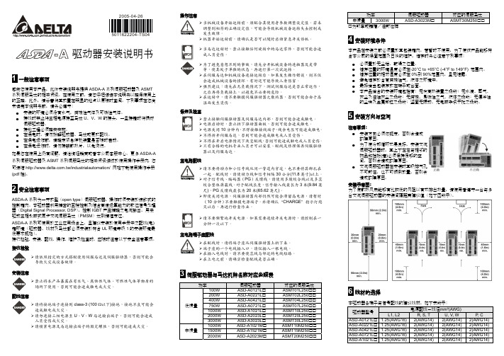
ASDA-A驱动器安装说明书
5 安裝方向與空間
注意事項: 安裝方向必須依規定,否則會造成 故障原因。 為了使冷卻循環效果良好,安裝交流 伺服驅動器時,其上下左右與相鄰的 物品和擋板(牆)必須保持足夠的空 間,否則會造成故障原因。 交流伺服驅動器在安裝時其吸排氣孔 不可封住,也不可傾倒放置,否則會 造成故障原因。
安裝示意圖: 為了使散熱風扇能夠有比較低的風阻以有效排出熱量,請使用者遵守一台與多 台交流伺服驅動器的安裝間隔距離建議值(如下圖所示)。
100W
200W
低慣量
400W 750W
1000W
2000W
3000W
中慣量
1000W 1500W
2000W
伺服驅動器
ASD-A0121L ASD-A0221L ASD-A0421L ASD-A0721L ASD-A1021L ASD-A2023L ASD-A3023L ASD-A1021M ASD-A1521M ASD-A2023M
ASD-A0721L 0.4(AWG26) 10 條 (4 對) UL2464 3 米 (9.84 英呎)
ASD-A1021L 0.4(AWG26) 10 條 (4 對) UL2464 3 米 (9.84 英呎)
ASD-A1021M 0.4(AWG26) 10 條 (4 對) UL2464 3 米 (9.84 英呎)
接收檢驗
請依照指定的方式搭配使用伺服馬達及伺服驅動器,否則可能會 導致火災或設備故障。
安裝注意
禁止將本產品暴露在有水氣、腐蝕性氣體、可燃性氣體等物質的 場所下使用,否則可能會造成觸電或火災。
配線注意
請將接地端子連接到 class-3 (100 Ω以下)接地,接地不良可能會 造成觸電或火災。 請勿連接三相電源至 U、V、W 馬達輸出端子,否則可能會造成 人員受傷或火災。 請鎖緊電源及馬達輸出端子的固定螺絲,否則可能造成火災。
台达ASDA—A2系列伺服助力构建刀库/刀塔系统

馈 单元 和 台达 等 多个 品 牌马 达 ;可 配合 多 品牌 NC系 统 ,只 需 I o 点控 制 ;支 持刀 位 记 忆等 。定 制 版 采用 ASDA— A2系列 伺 N. S - A 动 器 开发 Mo t i o n i n s i d e的 形式 ,大 幅 提升 功能 :可 区 分输 出刀 号与 报警 功能 ;能 够 自成 系统 ,简 化 NC 的控 制工 作 可 对
国轴 承进出口联 营公司发起 。并作 为西门子与
新政权就任 1 0 0天以后才能 看到其 产生 的影响”。 另一方面其国 内订单额完成 3 7 7亿 5 0 0 0万 日元 ,减少 4 . 6 % 。虽然受企业 设备投资 补助金待发放等 因素影响 ,汽车 、半导体相关行业需求仍稳步 发展。
刀片的对 称设计,能实 现左手及右 手方 向
的车削,并能在低的进给率下进行切槽加工。由
于新刀片的前端切削刃结构,加工槽底并非完全 平整。 因此,与现有的N P 型 刀片相 比.S C I R / L 2 2 - A D o 8 ・ 2 4 K 8 刀片在切槽加工中效率略低。 S C l R / L 2 2 一 A D 0 8 — 2 4 K 8 刀片主要推荐用于车 削及1 J \ 尺寸切槽加工,不推荐更多地用于其他切
中国机械 设备工 程股份有限 公司、 以及中国电
力工程有限公司等。
Audin SmartStep servo系统用户手册说明书
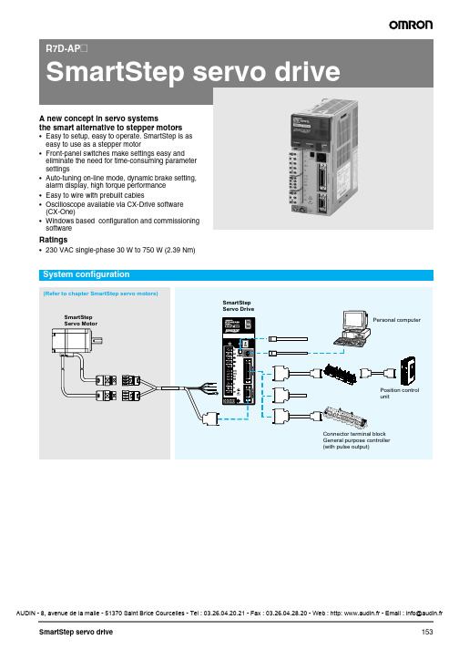
the smart alternative to stepper motors •Easy to setup, easy to operate. SmartStep is as easy to use as a stepper motor•Front-panel switches make settings easy and eliminate the need for time-consuming parameter settings•Auto-tuning on-line mode, dynamic brake setting, alarm display, high torque performance•Easy to wire with prebuilt cables•Oscilloscope available via CX-Drive software (CX-One)•Windows based configuration and commissioning softwareRatings•230 VAC single-phase 30 W to 750 W (2.39 Nm)General specificationsPerformance specificationsI/O specifications Terminal specificationsServo motor FamilyVoltage Models rated torque RemarksR7M-A (3000 min -1)230 V0.095 Nm to 2.39 NmRefer to the SmartStep servo motors chapter for detailsR7M-AP(3000 min -1)230 V 0.318 Nm to 2.39 Nm Refer to the SmartStep servo motors chapter for detailsItemSpecification Ambient operating temperature 0 to 55 °CAmbient operating humidity 90% max. (with no condensation)Ambient storage temperature -20 to 85 °CAmbient storage humidity90% max. (with no condensation)Storage/operating atmosphere No corrosive gases.Vibration resistance 10 to 55 Hz in X, Y, and Z directions with 0.1 mm double amplitude or acceleration of 4.9m/s 2 max., whichever is smallerImpact resistance Acceleration 19.6 m/s 2 max., in X, Y, and Z directions, three times Insulation resistance Between power line terminals and case:0.5 M Ω min. (at 500 VDC)Dielectric strength Between power line terminals and case:1,500 VAC for 1 min at 50/60 Hz Between each control signal and case:500 VAC for 1 min Protective structure Built into panel (IP10).International standardsApproval obtained for UL, cUL, and EN (EMC directiveand low-voltage directive)Item200 VAC input type 30 W 50 W 100 W 200 W 400 W750 WR7D-APA3H R7D-APA5H R7D-AP01H R7D-AP02H R7D-AP04H R7D-AP08H Continuous output current (rms)0.420.60.89 2.0 2.6 4.4Momentary maximum output current (rms) 1.3 1.9 2.8 6.08.013.9Control power supply Single-phase 200/230 VAC (170 to 253 V) 50/60 Hz Main-circuit power supply Single-phase 200/230 VAC (170 to 253 V) 50/60 Hz(three-phase 200/230 VAC can be used with the 750 W model.)Control method All-digital servoSpeed feedback 2,000 pulses/revolution incremental encoder Inverter method PWM method based on IGBT PWM frequency 11.7 kHz Weight0.80.80.80.8 1.1 1.7Compatible motor voltage 200 V Compatible motor capacity 30 W 50 W 100 W 200 W 400 W 750 W Command pulse response 250 kHz Applicable servo motor (R7M-)A03030A05030A10030AP10030A20030AP20030A40030AP40030A75030AP75030Control I/O (CN1) specificationsEncoder connector (CN2) specificationsCommunications connector (CN3) specificationsMonitor output (CN4) specificationsPin SymbolNameFunction1+PULS/CW/A Feed pulses, reverse pulses,or 90° phase difference pulses (A phase)Line-driver input: 7 mA at 3 V Open-collector input Input impedance: 200 ΩMaximum response frequency: 250 kppsPosition control is performed based on the pulses that have been input.2−PULS/CW/A 3+SIGN/CCW/B Direction signal, forward pulses,or 90° phase difference pulses (B phase)4−SIGN/CCW/B 5+ECRST Deviation counter resetLine-driver input: 7 mA at 3 VOpen-collector input: 16 mA at 5 V Input impedance: 200 ΩON: resets deviation counter.6−ECRST 7BKIR Brake interlock outputOutputs holding brake timing signals.8INP Positioning completed output ON when the position error is within the positioning completed range.10OGND Output ground commonGround common for output signals (pins 7 and 8).13+24V +24VDC power input for control Power supply input (+24 VDC) for pins 14 and 18.14RUN RUN command input ON: servo ON (starts power to servo motor)18RESET Alarm reset input ON: servo alarm status is reset.19GND RS-422A groundGround for RS-422A20RXD+RS-422A reception data Interface for RS-422A data transfers21RXD −22TXD+RS-422A transmission data23TXD −24RT Termination resistance terminalConnect to RXD- (pin 21) in the unit at the end of the line.32ZEncoder phase-Z open-collector outputOutput goes ON when the encoder’s phase-Z signal (1 pulse/revolution) is detected.Open-collector output: 20 mA max. at 30 VDC 33ZCOM 34ALMAlarm output Output goes OFF when alarm is detected.Open-collector output: 50 mA max. at 30 VDC 35ALMCOM ShellFGCable shield groundGround for cable's shield wire.Pin Symbol NameFunction1, 2, 3E0V Encoder power supply GND Power supply output for encoder4, 5, 6E5V Encoder power supply +5 V 8S+Encoder + phase-S input Line driver input (conforms to EIA-RS422A)(Input impedance: 220 Ω ± 5%)9S −Encoder − phase-S input 10A+Encoder + phase-A input Line driver input (conforms to EIA-RS422A)(Input impedance: 220 Ω ± 5%)11A −Encoder − phase-A input 12B+Encoder + phase-B input Line driver input (conforms to EIA-RS422A)(Input impedance: 220 Ω ± 5%)13B −Encoder − phase-B input ShellFGCable shield groundGround for cable's shield wire.Pin Symbol NameFunction1/TXD Transmission data Transmission data:RS-232C output Reception data:RS-232C input2/RXD Reception data 3PRMU Unit switching Switching terminal for a parameter unit7+5V +5 V output This is the +5 V power supply output to the parameter unit.8GND GroundShellFGCable shield groundGround for cable's shield wire.Pin Symbol NameFunction1NM Speed monitor Speed monitor output: 1 V per 1,000 r/min 2AM Current monitor Current monitor: 1 V / rated torque 3GND Ground Grounds for monitor output4GNDGroundGeneral specificationsFunction specificationsMode change specificationsItemSpecification Ambient operating temperature 0 to 55 °CAmbient operating humidity 90% max. (with no condensation)Ambient storage temperature -20 to 85 °CAmbient storage humidity90% max. (with no condensation)Storage/operating atmosphere No corrosive gases.Vibration resistance 10 to 55 Hz in X, Y, and Z directions with 0.1 mm double amplitude or acceleration of 9.8m/s 2 max., whichever is smallerImpact resistanceAcceleration 19.6 m/s 2 max., in X, Y, and Z directions, three timesItemFunctionSetting mode Display or change parameter settings.Monitor modeDisplay monitor values.Execute function mode Execute each function mode.Display alarms Display alarms that have occurred.Copy parametersRead or save parameters from the servo drive.Write parameters to the servo drive.Compare parameters in the servo drive with parameters in the parameter unit.Power ONComponentsSwitch operations Gain adjustment switchAdjusts the motor’s responsiveness.When this switch is set to 0, the unit will operate according to the set-tings in the internal parameters (Pn100, Pn101, Pn102, and Pn401).When this switch is set to 1 through F, the unit will operate according to the rotary switch’s setting.Decrease the switch setting to lower the motor’s responsiveness (i.e., so that it moves more smoothly).Increase the switch setting to raise the motor’s responsiveness (i.e., so that it moves faster).Unit number switch Gain adjustment switch DIP switchAutotuning switch• Resolution setting• Command pulse input setting • Dynamic brake settingAlarm indicator Monitor output connector (CN4)Control I/O connector (CN1)Communications connector (CN3)Encoder input connector (CN2)Servo motor power terminalsSetting Position loop gain Speed loop gainSpeed loopintegral constantTorquecommand filter time constant0Enables parameter settings(including settings other than gain settings).115154,000250220203,500200330303,000150440402,000100560601,50070685851,00050712012080030816016060020920020050015A 25025040010B 25025040010C 25025040010D 25025040010E 25025040010F25025040010Enable switch/parameter settingPin 6 of the DIP switch selects whether the servo drive operates according to theDIP switch settings or parameter settings.Online autotuning settingThe autotuning switch selects whether the gain will be adjusted auto-matically during operation.Resolution settingPins 4 and 5 select the positioning resolution.If the resolution is set to 1,000 (the default setting), the motor makesone revolution for every 1,000 pulses input.Command pulse input settingPin 3 selects the command pulse mode. Select “Forward pulse/reversepulse: positive logic” or “feed pulses/direction signal: positive logic.”Dynamic brake settingPin 2 enables or disables dynamic brake operation. If the dynamic brake is ena-bled, the motor can be brought to an emergency stop when the RUN commandgoes OFF or an alarm occurs.Alarm TableNote: 1.These parameters are read when the power is turnedON. Parameter Pn110.2 is valid when online.2.When using a regeneration resistor, set the resistor’scapacity when the temperature has risen to 120°C.Set this parameter to 0 if a regeneration resistor is notbeing used.Pin 6FunctionOFF Enables the DIP switch settings.ON Enables the parameter settings.Pins Resolution54OFF OFF1,000 pulses/revolution(0.36°/step)OFF ON10,000 pulses/revolution(0.036°/step)ON OFF500 pulses/revolution(0.72°/step)ON ON5,000 pulses/revolution(0.072°/step)(Default setting)Perform online autotuning.Complete online autotuning.The result is stored in the inertia ratioparameter (Pn103) and the servo driveruns.(Default setting)Pin 3Command pulse modeOFF Forward pulse/reverse pulse:positive logicON Feed pulses/direction signal:positive logicPin 2Dynamic brake modeOFF Dynamic brake disabled.ON Dynamic brake enabled.(Default setting)(Default setting)Display ALM output Error detection function Display ALM output Error detection functionA.04*OFF Parameter setting error A.7A OFF OverheatA.10*OFF Overcurrent A.bF*OFF System errorA.30OFF Regeneration error A.C1OFF Runaway detectedA.32OFF Regeneration overload A.C2*OFF Phase not detectedA.40OFF Overvoltage/undervoltage A.C3*OFF Encoder disconnect detectedA.51OFF Overspeed A.d0OFF Deviation counter overflowA.70OFF Overload CPF00---Parameter unit transmission error 1A.73OFF Dynamic brake overload CPF01---Parameter unit transmission error 2A.74OFF Inrush resistance overload A.91---Overload warningA.92---Regeneration overload warningServo drivesR7D-APA3H/APA5H/AP01H/AP02H (230 V, 30 to 200 W)R7D-AP04H (230 V, 400 W)R7D-AP08H (230 V, 750 W)FiltersR88A-FIW104-SER88A-FIW107-SE, R88A-FIW115-SEMounting dimensionsMounting dimensions5 dia. holeMounting dimensions5 dia. holeModelR88A-FIW107-SE R88A-FIW115-SE Dimensions in mmA 75 90B 240+5300+5C 50 60D 12 15E11.2Single-phase 200 to 230 VAC +10%/-15% (50/60 Hz)(the 750 W servo drives can input three-phase 200 to 230 VAC.)Connect the shield wire to theconnector shell.Note:*A regeneration resistor can be connected across the B1 and B2 terminals with 400W and 750W servo drives.When using an external regeneration resistor with a 400W servo drive, just connect it across the B1 and B2 terminals.When using an external regeneration resistor with a 750W servo drive, remove the jumper bar from the B2 and B3 terminals and then connect the regeneration resistor across the B1 and B2 terminals.Note:The symbols ABCDE ... show the recommended sequence to select the components in a SmartStep servo systemServo motorsNote:A Refer to the SmartStep servo motor chapter for detailed motor specifications and selection Servo drivesServo motor cables (for CN2)Standard cable (power + encoder)Flexible cables (power + encoder)SymbolSpecifications SmartStep drive model Compatible servo motors A Cylindrical type Flat type C200 VAC30 W R7D-APA3H R7M-A03030-@-50 W R7D-APA5H R7M-A05030-@-100 W R7D-AP01H R7M-A10030-@R7M-AP10030-@200 W R7D-AP02H R7M-A20030-@R7M-AP20030-@400 W R7D-AP04H R7M-A40030-@R7M-AP40030-@750 WR7D-AP08HR7M-A75030-@R7M-AP75030-@Control cables (for CN1)Cable for CN3Cable for CN4FiltersConnectorsExternal regeneration resistorParameter unit & computer softwareSymbolNameCompatible unitsModelAvailable lengths DServo relay unitUse with position control units(doesn’t support communications functions.)Units: CS1W-NC113/133, CJ1W-NC113/133, C200HW-NC113, and C200H-NC112XW2B-20J6-1B (1 axis)---Use with position control units(doesn’t support communications functions.)Units: CS1W-NC213/233/413/433, CJ1W-NC213/233/413/433, C200HW-NC213/413, C500-NC113/211, and C200H-NC211XW2B-40J6-2B (2 axes)Use with position control units(doesn’t support communications functions.)Units: CQM1H-PLB21, and CQM1-CPU43-V1XW2B-20J6-3B (1 axis)Use with position control units (supports communications functions.)Units: CS1W-NC213/233/413/433, CJ1W-NC213/233/413/433XW2B-40J6-4A (2 axes)Use with CJ1M-CPU22/23(doesn’t support communications functions.)XW2B-20J6-8A (1 axis)XW2B-40J6-9A (2 axes)E Cable to servo driveDoesn’t support communications functions. (For the XW2B-@@J6-@B)XW2Z-@@@J-B5 1 m or 2 m(the cable length goes in the empty boxes.)Supports communications functions. (For the XW2B-@@J6-4B)XW2Z-@@@J-B7FCable to position control unitCQM1H-PLB21 and CQM1-CPU43-V1XW2Z-@@@J-A30.5 m or 1 m(the cable length goes in the empty boxes.)C200H-NC112XW2Z-@@@J-A4C200H-NC211 and C500-NC113/211XW2Z-@@@J-A5CS1W-NC113 and C200HW-NC113XW2Z-@@@J-A8CS1W-NC213/413 and C200HW-NC213/413XW2Z-@@@J-A9CS1W-NC133XW2Z-@@@J-A12CS1W-NC233/433XW2Z-@@@J-A13CJ1W-NC113XW2Z-@@@J-A16CJ1W-NC213/413XW2Z-@@@J-A17CJ1W-NC133XW2Z-@@@J-A20CS1W-NC233/433XW2Z-@@@J-A21CJ1M-CPU22/23XW2Z-@@@J-A26G Control cableFor general-purpose controllersR88A-CPU @@@S 1 m or 2 m(the cable length goes in the empty boxes.)HConnector terminal block cableFor general-purpose controllers R88A-CTU @@@N Connector terminal blockXW2B-40F5-P---SymbolNameModelI Computer monitor cableR7A-CCA002P2SymbolNameModelJAnalog monitor cable R88A-CMW001SSymbolApplicable servo driveFilter model Rated current Rated voltageKR7D-APA3H, R7D-APA5H, R7D-AP01H, R7D-AP02H R88A-FIW104-E 4A 250 VAC single phaseR7D-AP04H R88A-FIW107-E 7A R7D-AP08H R88A-FIW115-E 15ASpecificationsModelControl I/O connector (for CN1)R88A-CNU01C SmartStep connectors kit.Models included in kit R7A-CNA00K-DESmartStep encoder connector (for CN2) R7A-CNA01RHypertac power connector female SPOC-06K-FSDN169Hypertac encoder connector femaleSPOC-17H-FRON169Hypertac power connector male (used in the motor)SRUC-06J-MSCN236Hypertac encoder connector male (used in the motor)SRUC-17G-MRWN087Specification Model220 W, 47 ΩR88A-RR22047SSpecificationsModelParameter copy unit (with cable)R7A-PR02A Configuration and monitoring software tool for servo drives and inverters. (CX-drive version 1.11 or higher)CX-drive Complete OMRON software package including CX-drive. (CX-One version 1.1 or higher)CX-OneIn the interest of product improvement, specifications are subject to change without notice.ALL DIMENSIONS SHOWN ARE IN MILLIMETERS.To convert millimeters into inches, multiply by 0.03937. T o convert grams into ounces, multiply by 0.03527.Cat. No. I46E-EN-01。
servo伺服电机(2024)

驱动器参数配置
根据电机参数和应用需求进行驱动器 参数配置,如电流环、速度环、位置 环等参数调整。
2024/1/30
13
调试技巧与注意事项
初始化设置
正确设置电机和驱动器的初始参 数,如电机类型、编码器类型、
通讯协议等。
2024/1/30
调试步骤
按照先开环后闭环、先低速后高速 的原则进行调试,逐步调整控制器 参数以达到最佳性能。
行业竞争日益激烈,国内外企业 纷纷加大研发投入,推出高性能
、高可靠性的伺服电机产品。
随着技术的不断进步和应用领域 的拓展,伺服电机企业需要不断 创新,提高产品附加值和竞争力
。
面对国际贸易摩擦和疫情等不确 定性因素,企业需要加强风险管 理,提高供应链稳定性和市场应
变能力。
2024/1/30
26
THANKS
市场需求
随着工业自动化程度的不断提高和智能制造的快速发展,伺服电机的市场需求不断增长 。同时,对伺服电机的性能、精度和可靠性等方面的要求也越来越高。未来,伺服电机
市场将继续保持快速增长态势,并向更高性能、更高精度和更智能化的方向发展。
6
02
伺服电机结构与组成
Chapter
2024/1/30
7
主要部件及功能
2024/1/30
能够实现高精度的位置 、速度和扭矩控制。
具有快速动态响应特性 ,适用于高速、高精度 运动控制场合。
能够实现宽范围的调速 ,满足不同应用需求。
5
采用高品质材料和先进 制造工艺,具有较高的 可靠性和稳定性。
应用领域及市场需求
2024/1/30
应用领域
伺服电机广泛应用于自动化设备、机器人、数控机床、印刷机械、包装机械、纺织机械 等领域。
asda系列伺服系统应用范洌手册
ASDA系列伺服系统是一种广泛应用于工业自动化控制领域的高性能伺服系统,其功能强大、稳定可靠,深受用户信赖。
本手册旨在为广大用户提供ASDA系列伺服系统的应用范例,帮助用户更好地理解和使用ASDA系列伺服系统,提高其在实际应用中的效率和性能。
一、ASDA系列伺服系统概述ASDA系列伺服系统是由台湾德马科技(Delta)生产的一种高性能伺服系统,具有速度响应快、定位精度高、控制精度高等特点,广泛应用于机械加工、印刷包装、电子设备等领域。
ASDA系列伺服系统包括伺服驱动器、伺服电机和控制器等组成,可根据实际需要选用不同规格和型号的产品,满足不同应用场景的需求。
二、ASDA系列伺服系统的应用范例1. 机床加工领域在数控机床中,ASDA系列伺服系统通常用于驱动主轴、进给轴和刀库等部件,实现高速、高精度的加工操作。
通过ASDA系列伺服系统,可以实现机床的精密切削、高速进给、自动换刀等功能,提高加工效率和加工质量。
2. 包装印刷领域在包装印刷设备中,ASDA系列伺服系统通常用于控制输纸、印刷、模切等运动部件,实现快速、稳定的生产。
通过ASDA系列伺服系统,可以实现印刷对位精度高、印刷速度快、自动调整等功能,提高生产效率和产品质量。
3. 电子设备领域在电子设备中,ASDA系列伺服系统通常用于控制输送、装配、检测等运动部件,实现高速、精密的生产。
通过ASDA系列伺服系统,可以实现设备运行稳定、生产效率高、产品质量可靠等功能,提高生产线的整体性能。
三、ASDA系列伺服系统的优势技术1. 高性能的磁编码器反馈技术ASDA系列伺服系统采用高性能的磁编码器反馈技术,具有高分辨率、高精度、低延迟等特点,可以实现对电机位置、速度、加速度等参数的实时精确控制,保证系统的稳定性和可靠性。
2. 快速的闭环控制算法ASDA系列伺服系统采用快速的闭环控制算法,具有响应速度快、控制精度高、稳定性好等特点,能够迅速响应外部指令,准确控制电机的运动状态,满足复杂工况下的运动控制需求。
路斯特ServoC系列伺服驱动器简易安装手册
请务必注意,本简要说明书仅作为电子版《ServoC 操作手册》的一个补充,而不是替代。
我们的目的是为了操作者和使用者快速掌握ServoC 伺服系统的安装和第一次投入运行的要点及注意事项。
该说明书仅适用于ServoC 驱动器及LSM 伺服电机,如用户选用第三方电机则必须参考《ServoC 操作手册》。
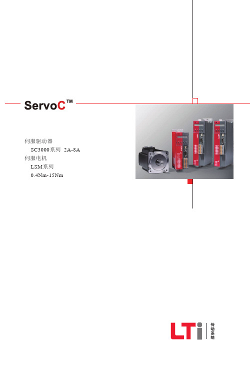
2重要提示)).主电源(底部)3AC 230 V 或 3AC 400 V外接控制电源1AC 230 V (3AC 230 V 系列 DC 24 V (3AC 400 V 系列电机与制动电阻接线端子操作面板6位7段 LED 显示屏4个调试按键RS485CANOpen 通讯端口(选件)USB 端口用于连接 PC I/O 端子2路模拟输入±10 V 输入(14位A/D 转换)1路模拟输出0-10 V 输出(8位A/D 转换)最大输出电流2 mA 7路数字输入光电隔离正负逻辑可选5路数字输出光电隔离最大输出电流40 mA24 V DC 供电输出(给I/O 端口最大输出电流200 mA )参考电压输出(10.5 V )电机温度传感器接口(PTC )编码器反馈接口标配:既可接旋转变压器,16位分辨率;也可接SinCos 单圈绝对值编码器(SEK ),18位分辨率脉冲输入/编码器仿真输出集电极开路或差分信号输入差分信号输出,Z 相集电极 开路输出允许三种类型的指令脉冲输入, 电子齿轮比:1/50<A/B <50硬件滤波,滤除干扰脉冲X1X5X4X6X7X8伺服驱动器接口示意图安装调试简要说明书1 安装接线说明41633 DriveManager调试说明附录A 总观所有的错误信息2 操作面板及其使用介绍3542总观所有的错误信息 (42)目录1.1 动力接线.......................................................................................41.2 编码器接线.......................................................................................51.3 通讯接口X5....................................................................................71.4 连接PC 和安装调试软件DriveManager ...................................................71.5 主令脉冲接线.................................................................................101.6 控制信号接线.................................................................................131.7 抱闸接线 (15)2.1 使用操作面板手动测试电机步骤.........................................................162.2 控制逻辑流程图..............................................................................192.3 操作面板参数详解 (20)3.1 DriveManager 调试说明 (35)安装调试简要说明书41.1 动力接线X1:电机动力电缆接线,使用菲尼克斯插头(随驱动器附赠)图1.1.1 LSML 电机动力插头X1U 、V 、W 分别对应颜色为:黄橙红(电机尾部甩线),或红棕蓝(路斯特传动制作的延长电缆);应使用带屏蔽动力电缆,屏蔽层双端接地(即接驱动器及电机的PE 端或外壳)并保证最大的接触面积; 为接地:黄绿线图1.1.2 LSMM电机动力插头管脚定义中惯量电机动力插头管脚定义12543中惯量电机动力插头管脚图安装调试简要说明书5X2、X3:驱动器电源接线,使用菲尼克斯插头(随驱动器附赠)图1.1.3 电源接线X2、X31.2 编码器接线图1.2.1 编码器接线(旋转变压器/Resolver )X4:编码器线,插头为15针D 形公头应使用双绞带屏蔽层编码器电缆,Sin-/Sin+为一对双绞线,Cos-/Cos+为一对双绞线,Ref-/Ref+为一对双绞线。
斯达特交流伺服驱动器使用手册说明书
斯达特交流伺服驱动器使用手册(第1版)斯达特官网: 电话:************E-mail:*****************目录第一章产品检查与安装 (5)1.1产品检查 (5)1.2安装与接线 (5)1.2.1安装方法 (5)1.2.2接线 (6)第二章接口 (7)2.1驱动器电源端子 (7)2.2控制信号输入/输出端子 (8)2.2.1输入信号 (8)2.2.2输出信号 (8)2.2.3编码器接口 (9)第三章输入/输出接口类型 (10)3.1开关量输入接口 (10)3.2开关量输出接口 (10)3.3机械制动器专用输出接口 (11)第四章参数和报警代码 (12)4.1参数说明 (12)4.2报警代码一览表 (13)第五章显示部分的构成 (14)5.1基本操作模式 (15)5.2参数修改模式 (16)5.3试运转 (17)第六章斯达特系统与伺服驱动器的应用实例 (18)第七章伺服驱动器规格 (19)7.1型号 (19)7.2规格 (19)7.3伺服驱动器尺寸图 (20)7.4伺服驱动器与伺服电机适配 (21)7.560系列电机参数 (21)7.680系列电机参数 (22)7.7110系列电机参数 (23)7.8130系列电机参数 (23)安全注意事项错误操作可能会引起危险并导致人身伤亡。
错误操作可能会引起危险,导致人身伤害,并可能使设备损坏。
严格禁止行为,否则会导致设备损坏或不能使用。
1.使用场合禁止将产品暴露在有水气、腐蚀性气体、可燃性气体的场合使用。
否则会导致触电或火灾。
2.配线请将接地端子可靠接地,接地不良可能会造成触电或火灾。
3.操作必须配合合适的参数设定值。
4.运行禁止接触任何旋转中的零件,否则会造成人员伤亡。
设备运行时,5.保养和检查禁止接触驱动器及其电机内部,否则会造成触电。
6.使用范围请勿用于可能直接危害人身安全的装置上,第一章产品检查与安装1.1 产品检查本产品在出厂前均做过完整功能测试,为防止产品运送过程中因疏忽导致产品不正常第,拆封后请详细检查下列事项:检查伺服驱动器与伺服电机型号是否与订购的机型相同。
DELTA ASD-PU-01B 数位操作器 显示 操作说明

ASD-PU-01B數位操作器/顯示操作說明1一般注意事項感謝您使用本產品,此份說明書提供ASD-PU-01B 的相關信息。
在使用之前,請您仔細詳讀本說明書以確保使用上的正確。
此外,請將它妥善放置在明顯的地點以便隨時查閱。
下列事項在您尚未讀完本說明書前,請務必遵守: z 安裝的環境必須沒有水氣,腐蝕性氣體與可燃性氣體。
z 請注意接線配置的問題,裝配錯誤可能導致產品毀損。
z 請勿大力敲擊、摔放,或是採取不當方式操作本產品。
z請勿破壞線材外觀或是自行拆解本產品。
如果您在使用上仍有問題,請諮詢經銷商或者本公司客服中心。
2安全注意事項ASD-PU-01B 為搭配台達伺服產品 ASDA-B 的數位操作器。
本產品內建4組存儲器可供存儲和寫入驅動器內部的參數組,並提供特殊功能鍵(內含快速參數編譯, 異常重置, 參數儲存/寫出, 寸動模式, 馬達增益動/靜態調整功能)方便操作應用。
ASDBCADK0001通訊線與ASD-PU-01A 連接時,如需要使用螺絲固定,建議採用自攻螺絲φ3*1.06*8規格。
接收檢驗、安裝、配線、操作、維護及檢查時,應隨時注意以下安全注意事項。
接收檢驗及安裝¾ 請依照指定的方式搭配伺服驅動器,否則可能會導致故障。
¾ 禁止將本產品暴露在有水氣、腐蝕性氣體、可燃性氣體等物質的場所下使用,否則可能會造成故障。
配線注意¾ 請注意接線兩端的裝配方向,否則可能造成故障。
操作注意¾ 請勿大力摔放、敲打,或是不當方式操作,否則可能造成故障。
維護及檢查¾ 請勿自行拆解本產品,或是任意破壞線材外觀,否則可能造成產品損壞。
3數位操作器ASD-PU-01B各部說明4驅動器與數位操作器Keypad 通訊線台達型號:ASDBCADK00015 ASD-PU-01B 操作流程圖監控狀態(監控模式)與參數編輯(參數模式)功能操作流程圖參數快速編輯異常重置寸動模式使用鍵離開功能,當下次再進入功能時,會顯示上次跳離前的狀態。
SGDA Series Driver 使用说明书

SGDA Series Driver使用说明书V1.0交流伺服驱动器型号:SGDA7R6AP1.5~5.5KW请将此使用说明书,交给最终用户,并妥善保存南京开通自动化技术有限公司Nanjing KaiTong Automation Technology Co.,Ltd序言感谢您惠购南京开通自动化技术有限公司生产的SG系列伺服驱动器。
SG系列伺服驱动器是南京开通自动化技术有限公司研制、开发生产的高品质、多功能、低噪音的交流伺服驱动器。
SG系列伺服驱动器可对伺服电机的位置、转速、加速度和输出转矩方便地进行控制,SG系列伺服驱动器的研制成功为传动控制领域带来了无限生机。
SG系列伺服驱动器核心采用32位C P U,实现对电机全数字控制,是机械制造业最具竞争力的电气传动产品。
SG系列通用伺服驱动器,是根据自动化领域,针对位置、速度、力矩控制要求而开发,是数控机床、纺织、塑机、造纸及各种自动化流水线等运动控制领域的首选产品。
在使用SG系列伺服驱动器之前,请您仔细阅读该手册,以保证正确使用。
错误使用可能造成驱动器运行不正常、发生故障或降低使用寿命,乃至发生人身伤害事故。
因此使用前应反复阅读本说明书,严格按说明使用。
本手册为随机发送的附件,务必请您使用后妥善保管,以备今后对驱动器进行检修和维护时使用。
安全注意事项在产品存放、安装、配线、运行、检查或维修前,用户必需熟悉并遵守以下重要事项,以确保安全地使用本产品。
目录第1章概要 (1)1.1SGDA系列伺服驱动器 (1)1.2伺服单元格部分名称 (1)1.3伺服单元的额定值和规格 (1)第2章面板操作 (3)2.1面板操作器按键的名称及功能 (3)2.2功能的切换 (3)2.3状态显示 (4)2.4参数设定的操作示例 (5)第3章接线与连接 (6)3.1主回路的接线 (6)3.2输入输出信号的连接 (6)3.3编码器连接器(CN2)的端口排列 (9)3.4泄放电阻的连接 (10)第4章辅助功能(Fn) (12)4.1报警记录的显示(Fn000) (12)4.2JOG运行(Fn002) (13)4.3程序JOG运行(Fn004) (13)4.4参数初始化(Fn005) (14)4.5报警记录的删除(Fn006) (14)4.6绝对值编码器复位(Fn008) (14)4.7参数的写入禁止设定(Fn010) (15)第5章监视功能(Un) (16)第6章故障诊断 (18)6.1警报一览表 (18)6.2警告一览表 (21)第7章参数 (22)1第1章概要1.1SGDA 系列伺服驱动器SGDA 系列主要用于需要“高速、高频度、高定位精度”的场合,该伺服单元可以在最短的时间内最大限度地发挥机械性能,有助于提高生产效率。
埃斯顿PRONET伺服系统调试方法

设定的斜率 指令电压 (V)
Pn400
1.调试准备事项 2.调试控制参数 指令转矩 (%) 模拟指令自动 调整偏移量
指令转矩 偏移量手动调整范围 (%) (-1024~+1024)
3.监视 及 辅助
4.增益参数调试 5.报警 及 排除 指令电压 (V) 指令电压 (V)
Fn003效果图
Fn004效果图
4.增益参数调试 5.报警 及 排除
PRONET伺服调试控制参数 PNP型集电极开路指令信号接线图
1.调试准备事项 2.调试控制参数
3.监视 及 辅助
4.增益参数调试 5.报警 及 排除
PRONET伺服调试控制参数 电子齿轮比的计算方法
1.调试准备事项 2.调试控制参数
3.监视 及 辅助
4.增益参数调试 5.报警 及 排除
1.调试准备事项 2.调试控制参数 指令速度 (rpm) 模拟指令自动 调整偏移量 指令速度 (rpm) 指令电压 (V)
偏移量手动调整范围 (-1024~+1024)
3.监视 及 辅助
4.增益参数调试 5.报警 及 排除
指令电压 (V)
Fn003效果图
Fn004效果图
PRONET伺服调试控制参数 Pn306、Pn307效果图
3.监视 及 辅助
4.增益参数调试 5.报警 及 排除
PRONET伺服调试控制参数 差分指令信号接线图
1.调试准备事项 2.调试控制参数
3.监视 及 辅助
4.增益参数调试 5.报警 及 排除
PRONET伺服调试控制参数 NPN型集电极开路指令信号接线图
1.调试准备事项 2.调试控制参数
3.监视 及 辅助
ESTUN伺服系统的调试
ESTUN-EDB交流伺服驱动器手册2.0V
安装面
通风
3
4
EDB系列交流伺服随机手册
EDB系列交流伺服随机手册
■
伺服电机的安装尺寸ຫໍສະໝຸດ 1.2 伺服驱动器的安装尺寸
在伺服驱动器不使用时,请在[-20~+60℃]的温度范围内进行保管。
EDB-08AMA
200~230V INPUT ACPHASE 3 AC 0~200V 0.8KW 50/60Hz 4.8A 4.0A
键 QK QL W
40 55 55 55 5 6 6 6 8 10 10 10
T
7 8 8 8
U
4 5 5 5
10APA 265(319.5) 210(264.5) 134 185(187.5) 118 20APA 332(401) 253(322) 168 228(245) 140 30APA 40APA
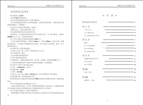
B1,B2,B3 (EDB-08, EDB-10 再生单元连接端子 EDB-15无B3端子) 1 2 电源高次谐波抑制 (EDB-08, EDB-10 用电抗器连接端子 EDB-15无此二端子) (EDB-08, EDB-10 EDB-15无此端子)
概 要 三相交流 200~230V 单相交流 200~230V 与电机连接。 与电源接地和电机接地端子连接,进行接地处理。
200 114.3 13.5 200 114.3 13.5
(注)括号内的数值表示的是带制动器电机的尺寸。
5
6
EDB系列交流伺服随机手册
第二章
2.1 主电路的配线
在配线时,请务必遵守下述的注意事项。
配
线
!
注意
请不要将动力线和信号线从同一管道内穿过,也不要将其绑扎在一起。进 行配线时,请使动力线和信号线相隔30cm以上。 对于信号线、编码器(PG)反馈线,请使用多股绞合线以及多芯绞合整体 屏蔽线。 对于配线长度,指令输入线最长为3m,PG反馈线最长为20m。 即使关闭电源,伺服驱动器内部仍然可能会滞留有高电压,请暂时不要触 摸电源端子。 请在确认CHARGE指示灯熄灭以后,再进行检查工作。 请不要频繁地ON/OFF电源。在需要反复地连续ON、OFF电源时,请控制在 每分钟1次以下。 由于在伺服驱动器的电源部分,有大电容,所以在ON电源时,会流过较大 的充电电流(充电时间0.2秒)。 因此,如果频繁地ON/OFF电源,则会造成伺服驱动器内部的主电路元件性 能下降。 1) 主电路端子的名称及功能 端子记号 L1,L2,L3 L1C,L2C U,V,W 功 能 主回路电源输入端子 控制电源输入端子 电机连接端子 接地端子
ASDA交流伺服驱动系统系列

ASDA交流伺服驱动系统系列交流伺服驱动器随着微处理器技术的日新月异,大功率、高性能半导体功率器和伺服电机所需永磁材料制造工艺的发展及其性价比不断提高,交流伺服电机和交流伺服控制系统已经成为当前工业领域中,实现自动化的基础技术。
台达ASDA交流伺服驱动器以掌握核心的电子技术为基础,针对不同产业机械的客户需求进行研发;提供全方位的伺服系统产品。
全系列产品的控制回路均采用高速数字信号处理器(DSP),配合增益自动调整、指令平滑功能的设计以及软件分析与监控,可达到高速位移、精准定位等运动控制需求。
ASDA-A+系列(new)本系列是台达进阶泛用型的交流伺服驱动系统。
规格上,编码器的分辨率提升到20bit(1280000p/rev);对于需要高精度加工的工具机产业,能够提供更精准的控制。
对于需要高扭力输出的应用设备,ASDA-A+提供了3.0kW到7.5kW的高扭力选择(19.1N.M~47.74N.M)。
规格特性:1.ASDA-A+伺服驱动器包含4.5kW,5.5kW,7.5kW2.全系列机种均为交流三相220V电压输入3.编码器分辨率为20bit(1280000p/rev)4.ECMA伺服电机包含3kW,4.5kW,5.5kW,7.5kW5.电机惯量型式皆为中高惯量(54.95E-4kg.m2~142.7E-4kg.m2)6.内置简易运动模式;支持原点复归、分度功能、自动循环定位等模式7.高速脉冲输入功能,可搭配台达PLC产品–DVP20PM达到两轴同动,圆弧插补等精密控制8.支持MODBUS通讯控制(RS-485RS-422RS-232),ASCIIRTU通讯协议9.ASDA-A+驱动器内设电机匹配选择功能最佳应用:弹簧机械、弯管机械、折床机械、NC送料机械、全电射出机、龙门综合加工机械ASDA-B系列本系列是台达标准功能型的交流伺服驱动系统。
除了提供容易操控的手持式面板,并搭配友善的软件操作界面,能快速进行伺服驱动增益调试及状态监控,并提供多样化的电机容量选择。
- 1、下载文档前请自行甄别文档内容的完整性,平台不提供额外的编辑、内容补充、找答案等附加服务。
- 2、"仅部分预览"的文档,不可在线预览部分如存在完整性等问题,可反馈申请退款(可完整预览的文档不适用该条件!)。
- 3、如文档侵犯您的权益,请联系客服反馈,我们会尽快为您处理(人工客服工作时间:9:00-18:30)。
The Encoder Resolution
Three Scales of Encoder Resolution • The 2500 ppr encoder, which is an AB-phase encoder, will send out 10000 pulses per revolution.
Abundant Operation Modes
The Table Beside is for ASDA-A2 • Most of the operation modes are shared by all series. • Please reference to user manuals for details.
Mode 00 01 02 03 04 05 Dual Mode 06 07 08 09 0A CANopen Mode 0D Multiple Mode 0E 0F Pt Pr S T Sz Tz Single Mode
The Control Skeleton
Multiple Cascaded Loops • Position loop, Speed loop, and Current loop.
20 bits => 1,280,000 p/r (> 220=1,048,576)
The Advantage of High Resolution
Several Advantages • The position of a rotor cannot be known until it is at the division point. • The higher resolution, the more positing accuracy. • The higher resolution, the better low speed stability. • The higher resolution, the smaller acoustical noise.
ASDA-AB 10000 p/rev 450 Hz 100 w ~ 2 kw
ASDA-B 10000 p/源自ev 250 Hz 100 w ~ 2 kw
ECMA Servo Motor
The Power Range 0.1kW ~ 7.5kW
• • • •
Rated Torque: 0.32 N-m ~ 47.74 N-m Max. Torque: 0.96 N-m ~ 119.36 N-m Rotation Speed: 1000 rpm ~ 5000 rpm Encoder Resolution: 2500 ppr,17 bits, 20 bits
The Rigidity
Connected to the Response of a System • The more rigid a system, the higher bandwidth it is . • The resonance frequency of a rigid system is always higher. • It must be taken into account during the developing phase of a machine.
The Control Skeleton
Three Cascaded Loops, Position Control Loop, Speed Control Loop, and Torque Control Loop
Scope Skill
How to Measure Resonance, Performance Monitoring, and Inertia Evaluation
Position Command and Source Selection • Pulse Type Selection, Control Mode, Electronic Gear Ratio, Moving Filter, and Position Control Unit.
The Position and Speed (1)
Presentation Revision
Revision: 1/24/2010 Revision: Rev. 1/21/2010 is abandoned.
Table of Contents
The Background Knowledge
A Glance of ASDA Series Servo System, Resolution of Encoder, Response, Bandwidth, Stiffness, and Rigidity
TUNING ASDA SERIES SERVO SYSTEMS
About This Presentation
Intended Audience
Basic level, for the users who knows how to operate ASDA series servo systems.
The Whole ASDA Series
ASDA-A2 1280000 p/rev (20 bits) 1000 Hz 100 w ~ 5.5 kw ASDA-B2 160000 p/rev (17 bits) 550 Hz 100 w ~ 3 kw ASDA-A 10000 p/rev 450 Hz 100 w ~ 3 kw ASDA-A+ 1280000 p/rev (20 bits) 550 Hz 4.5 kw ~ 7.5 kw
• The notation of a 20-bits encoder represents for its level instead of the number of divisions per revolution, because it communicates with servo motor via communication protocol not pulse signal. • 17 bits => 160,000 p/r (> 217=131,072)
A Stable System
Industry V.S. Academic • The stability is defined to a system before it turns to self-oscillating in academic. • It is unreal for industry even it is not self-oscillating. • The stability is asked to fit the requirements of operation of a machine; excellent smooth speed and accurately positioning performance in CNC world, for example.
Position Control Loop
Position Control Path • Position Command Unit, Position Control Unit, Speed Loop, Current Loop, and Vibration Suppression Unit.
Position Command Unit
Acceleration Zone Stop Zone Constant Speed Zone Position Curve Deceleration Zone Stop Zone Acceleration Zone Stop Zone Constant Speed Zone Position Curve Deceleration Zone Stop Zone
The Position-Speed-Torque
From the View of Real World • The Impulse function does not exist in physical world; that is another perspective to see why we need S-Curve. • If the acceleration or deceleration zone is short, the system should be with the ability to offer tremendous power in a short time or the drive will operate in saturation and cannot follow the command well.
The Position Curve Defines Speed • The longer the distance moved per unit time, the higher the speed will be.
The Position and Speed (2)
Why the S-Curve needed • To generate an acceleration zone and a deceleration zone is necessary for a smooth movement.
The Stiffness
To Evaluate the Ability of a System to Resist Disturbance • Disturbance exists everywhere. • All movements lead to load change can be attributed to disturbance. • Higher gain means faster response which can adjust the system to get rid of load change effect fast.
