JE915HSTR2中文资料
HD74ALVC2G08US中文资料

Item Propagation delay time
•
VCC = 3.3±0.3 V
Symbol tPLH tPHL Min 1.0 Typ Max 2.8 Unit ns Test conditions CL = 30 pF FROM (Input) A or B TO (Output) Y
Conditions
Output voltage range
Output : H or L VCC : OFF
Input clamp current Output clamp current Continuous output current Continuous current through VCC or GND Maximum power dissipation *3 at Ta = 25°C (in still air) Storage temperature Notes:
Package type SSOP-8 pin Package code TTP-8DB Package suffix US Taping code E (3,000 pcs / Reel)
HD74ALVC2G08
Outline and Article Indication
• HD74ALVC2G08
µA µA µA pF
VIN = 3.6 V or GND VIN = VCC or GND, IO = 0 VIN or VO = 0 to 3.6 V VIN = VCC or GND
Note: For conditions shown as Min or Max, use the appropriate values under recommended operating conditions.
RCS-915AS说明书
RCS-915AS微机母线保护装置 技术说明书使用说明书调试大纲南瑞继保电气有限公司南瑞继保电气有限公司版权所有2004.3(V1.3) 此说明书对应版本号为2.10及以下的程序,详细的程序版本更新情况请参见附录2。
注:2.10以下与2.10及以上版本程序的断路器失灵保护逻辑不同。
本说明书和产品今后可能会有小的改动,请注意核对实际产品与说明书的版本是否相符。
更多产品信息,请访问互联网:http://www.nari-relays.com 业务联系 电话:(025)83406078 83439746 传真:(025)83438965 技术支持 电话:(025)52100561 传真:(025)52100597 工程服务 电话:(025)52107703 传真:(025)52100770 质量保证 电话:(025)52100660 目录1概述 (1)1.1应用范围 (1)1.2保护配置 (1)1.3性能特征 (1)2技术参数 (1)2.1额定参数 (1)2.2功耗 (1)2.3电源 (1)2.4主要技术指标 (2)2.5环境参数 (2)2.6电磁兼容 (2)2.7绝缘试验 (2)2.8机箱参数及安装方式 (2)2.9通讯 (2)3工作原理 (2)3.1装置硬件配置 (2)3.2原理说明 (3)4软件说明 (16)4.1保护的程序结构 (16)4.2采样程序 (16)4.3正常运行程序 (16)4.4故障计算程序 (16)5装置整体介绍 (17)5.1输出接点 (17)5.2装置接线端子 (18)5.3结构与安装 (22)6整定方法及用户选择 (24)6.1装置参数定值 (24)6.2系统参数定值 (25)6.3母差保护定值 (27)6.4失灵保护定值 (30)7装置使用说明 (36)7.1装置液晶显示说明 (36)7.2命令菜单使用说明 (39)8调试大纲 (42)8.1试验注意事项 (42)8.2交流回路校验 (42)8.3输入接点检查 (42)8.4整组试验 (42)8.5输出接点检查 (45)8.6开关传动试验 (45)8.7带负荷试验 (45)9装置的运行说明 (46)9.1装置的组成 (46)9.2装置异常信息含义及处理建议 (46)9.3安装注意事项 (48)9.4保护运行注意事项 (48)附录1:模拟盘简介 (49)附录2:程序版本更新情况 (53)1概述1.1 应用范围RCS-915AS型微机母线保护装置,适用于各种电压等级的双母双分段主接线方式,由两套装置完成双母双分段母线的保护。
淼田电子有限公司LQG15HH系列芯片电感说明书
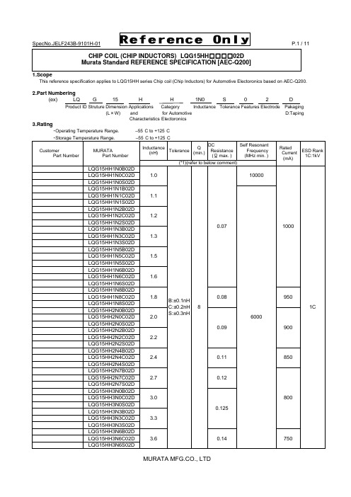
SpecNo.JELF243B-9101H-01 P.1 / 11Reference OnlyCHIP COIL (CHIP INDUCTORS) LQG15HH □□□□02DMurata Standard REFERENCE SPECIFICATION [AEC-Q200]1.ScopeThis reference specification applies to LQG15HH series Chip coil (Chip Inductors) for Automotive Electoronics based on AEC-Q200.2.Part Numbering(ex) LQ G 15 H H 1N0 S 0 2 DProduct ID Struture Dimension Applications Category Inductance Tolerance Features Electrode Pakaging(L ×W) and for Automotive D:TapingCharacteristics Electoronics3.Rating・Operating Temperature Range. –55°C to +125°C ・Storage Temperature Range. –55°C to +125°CCustomer Part Number MURATAPart NumberInductance (nH) ToleranceQ(min.)DC Resistance (Ω max. ) Self ResonantFrequency (MHz min. )Rated Current (mA)ESD Rank 1C:1kV(*1)(refer to below comment)LQG15HH1N0B02D1.0B:±0.1nHC:±0.2nH S:±0.3nH8 0.07 10000 10001CLQG15HH1N0C02D LQG15HH1N0S02D LQG15HH1N1B02D1.1 6000 LQG15HH1N1C02DLQG15HH1N1S02D LQG15HH1N2B02D 1.2 LQG15HH1N2C02D LQG15HH1N2S02DLQG15HH1N3B02D1.3 LQG15HH1N3C02DLQG15HH1N3S02D LQG15HH1N5B02D1.5 LQG15HH1N5C02DLQG15HH1N5S02D LQG15HH1N6B02D 1.6 LQG15HH1N6C02D LQG15HH1N6S02D LQG15HH1N8B02D 1.8 0.08 950LQG15HH1N8C02D LQG15HH1N8S02DLQG15HH2N0B02D2.0 0.09 900LQG15HH2N0C02DLQG15HH2N0S02DLQG15HH2N2B02D 2.2 LQG15HH2N2C02D LQG15HH2N2S02D LQG15HH2N4B02D2.4 0.11 850 LQG15HH2N4C02DLQG15HH2N4S02D LQG15HH2N7B02D 2.7 0.12 800 LQG15HH2N7C02D LQG15HH2N7S02D LQG15HH3N0B02D 3.0 0.125LQG15HH3N0C02D LQG15HH3N0S02DLQG15HH3N3B02D3.3 LQG15HH3N3C02DLQG15HH3N3S02D LQG15HH3N6B02D3.6 0.14 750 LQG15HH3N6C02DLQG15HH3N6S02DCustomer Part Number MURATAPart NumberInductance (nH) ToleranceQ(min.)DC Resistance (Ω max. ) Self ResonantFrequency(MHz min. )RatedCurrent(mA)ESD Rank 1C:1kV(*1)(refer to below comment)LQG15HH3N9B02D3.9 B:±0.1nHC:±0.2nHS:±0.3nH8 0.14 6000 7501CLQG15HH3N9C02DLQG15HH3N9S02DLQG15HH4N3B02D 4.3 LQG15HH4N3C02D LQG15HH4N3S02D LQG15HH4N7B02D 4.7 0.16 700LQG15HH4N7C02D LQG15HH4N7S02DLQG15HH5N1B02D5.1 0.18 5300 650LQG15HH5N1C02DLQG15HH5N1S02DLQG15HH5N6B02D5.6 4500 LQG15HH5N6C02DLQG15HH5N6S02D LQG15HH6N2B02D6.2 0.20 600LQG15HH6N2C02DLQG15HH6N2S02DLQG15HH6N8G02D6.8 G:±2%H:±3%J:±5%0.22 LQG15HH6N8H02DLQG15HH6N8J02D LQG15HH7N5G02D 7.5 0.24 4200 550LQG15HH7N5H02D LQG15HH7N5J02DLQG15HH8N2G02D 8.2 3700 LQG15HH8N2H02D LQG15HH8N2J02DLQG15HH9N1G02D 9.1 0.26 3400500LQG15HH9N1H02D LQG15HH9N1J02DLQG15HH10NG02D10 LQG15HH10NH02D LQG15HH10NJ02D LQG15HH12NG02D12 0.28 3000 LQG15HH12NH02DLQG15HH12NJ02DLQG15HH15NG02D15 0.32 2500 450 LQG15HH15NH02DLQG15HH15NJ02D LQG15HH18NG02D18 0.36 2200 400 LQG15HH18NH02DLQG15HH18NJ02D LQG15HH22NG02D 22 0.42 1900 350 LQG15HH22NH02D LQG15HH22NJ02D LQG15HH27NG02D 27 0.46 1700 LQG15HH27NH02D LQG15HH27NJ02D LQG15HH33NG02D33 0.58 1600 LQG15HH33NH02DLQG15HH33NJ02D LQG15HH39NG02D39 0.65 1200 300 LQG15HH39NH02DLQG15HH39NJ02DCustomer Part Number MURATAPart NumberInductance (nH) Tolerance Q(min.) DC Resistance (Ω max. ) Self Resonant Frequency (MHz min. )Rated Current (mA)ESD Rank 1C:1kV(*1)(refer to below comment)LQG15HH47NG02D 47 G:±2%H:±3%J:±5%8 0.72 1000 3001CLQG15HH47NH02D LQG15HH47NJ02DLQG15HH56NG02D 56 0.82 800 250LQG15HH56NH02D LQG15HH56NJ02DLQG15HH68NG02D68 0.92 LQG15HH68NH02DLQG15HH68NJ02D LQG15HH82NG02D82 1.20 700 200 LQG15HH82NH02DLQG15HH82NJ02D LQG15HHR10G02D100 1.25 600 LQG15HHR10H02DLQG15HHR10J02DLQG15HHR12G02D120 1.30 LQG15HHR12H02DLQG15HHR12J02DLQG15HHR15G02D 150 2.99 550 150LQG15HHR15H02D LQG15HHR15J02DLQG15HHR18G02D 180 3.38 500 LQG15HHR18H02D LQG15HHR18J02D LQG15HHR22G02D 220 3.77 450 120 LQG15HHR22H02D LQG15HHR22J02D LQG15HHR27G02D270 4.94 400 110 LQG15HHR27H02DLQG15HHR27J02D(*1) Standard Testing Conditions《Unless otherwise specified 》 《In case of doubt 》Temperature : Ordinary Temperature / 15°C to 35°C Temperature: 20°C ± 2°CHumidity :Ordinary Humidity / 25%(RH) to 85%(RH) Humidity : 60%(RH) to 70%(RH) Atmospheric Pressure : 86kPa to 106 kPa4. Appearance and Dimensions■Unit Mass (Typical value)6.Q200 Requirement6.1.Performance (based on Table 5 for Magnetics(Inductors / Transformer)AEC-Q200 Rev.D issued June 1. 2010AEC-Q200 Murata Specification / Deviation No Stress TestMethod3 HighTemperatureExposure 1000hours at 125 deg CSet for 24hours at roomtemperature, then measured.Meet Table A after testing.Table A4 TemperatureCycling 1000cycles-40 deg C to +125 deg CSet for 24hours at roomtemperature,thenmeasured.Meet Table A after testing.7 Biased Humidity 1000hours at 85 deg C, 85%RHunpowered.Meet Table A after testing.8 Operational Life Apply 125 deg C 1000hoursSet for 24hours at roomtemperature, then measuredMeet Table A after testing.9 External Visual Visual inspection No abnormalities10 Physical Dimension Meet ITEM 4(Style and Dimensions)No defects12 Resistanceto Solvents PerMIL-STD-202Method 215Not ApplicableAppearance No damageInductanceChange(at 100MHz)Within ±10%AEC-Q200 Murata Specification / Deviation No Stress TestMethod13 Mechanical Shock Per MIL-STD-202Method 213Condition C : 100g’s(0.98N),6ms, Half sine, 12.3ft/sMeet Table A after testing.14 Vibration 5g's(0.049N) for 20 minutes,12cycles each of 3 oritentationsTest from 10-2000Hz.Meet Table A after testing.15 Resistanceto Soldering Heat No-heatingSolder temperature260C+/-5 deg CImmersion time 10sMeet Table A after testing.Pre-heating 150C +/-10 deg C, 60s to 90s17 ESD Per AEC-Q200-002 ESD Rank: refer to the Item3 (Rating).Meet Table A after testing18 Solderbility Per J-STD-002 Method b : Not Applicable90% of the terminations is to be soldered.19 ElectricalCharacterizationMeasured : Inductance No defects20 Flammability Per UL-94 Not Applicable21 Board Flex Epoxy-PCB(1.6mm)Deflection 2mm(min)Holding time 60s Meet Table B after testing.Table BAppearance No damage DCresistanceChangeWithin ±10%22 Terminal Strength Per AEC-Q200-006A force of 17.7Nfor 60s Murata Deviation Request: 5N No defects7.Specification of Packaging(in mm)7.2 Specification of Taping(1) Packing quantity (standard quantity)10,000 pcs. / reel(2) Packing MethodProducts shall be packed in the cavity of the base tape and sealed by top tape and bottom tape.(3) Sprocket holeThe sprocket holes are to the right as the tape is pulled toward the user.(4) Spliced pointBase tape and Top tape has no spliced point.(5) Missing components numberMissing components number within 0.1 % of the number per reel or 1 pc., whichever is greater,andare not continuous. The Specified quantity per reel is kept.0.8m ax.7.3 Pull StrengthTop tape5N min.Bottom tape7.4 Peeling off force of cover tapeSpeed of Peeling off 300mm/min Peeling off force0.1N to 0.6N(minimum value is typical)7.5 Dimensions of Leader-tape,Trailer and ReelThere shall be leader-tape ( top tape and empty tape) and trailer-tape (empty tape) as follows.7.6 Marking for reelCustomer part number, MURATA part number, Inspection number(*1) ,RoHS Marking(*2), Quantity etc ・・・*1) <Expression of Inspection No.> □□ OOOO ⨯⨯⨯(1) (2) (3)(1) Factory Code (2) Date First digit : Year / Last digit of yearSecond digit: Month / Jan. to Sep. → 1 to 9, Oct. to Dec. → O, N, D Third, Fourth digi : Day(3) Serial No.*2) <Expression of RoHS Marking> ROHS – Y (△)(1) (2)(1) RoHS regulation conformity parts. (2) MURATA classification number7.7 Marking for Outside package (corrugated paper box)Customer name, Purchasing order number, Customer part number, MURATA part number, RoHS Marking(*2) ,Quantity, etc ・・・7.8. Specification of Outer CaseOuter Case Dimensions(mm)Standard Reel Quantityin Outer Case (Reel)W D H 186 186 93 5* Above Outer Case size is typical. It depends on a quantity of an order.F165to 180degreeTop tape Bottom tapeBase tapeWDLabelH8. △!Caution8.1 Caution(Rating)Do not exceed maximum rated current of the product. Thermal stress may be transmitted to the product and short/open circuit of the product or falling off the product may be occurred.8.2 Fail-safe Be sure to provide an appropriate fail-safe function on your product to prevent a second damage that may becaused by the abnormal function or the failure of our product.8.3 Limitation of ApplicationsPlease contact us before using our products for the applications listed below which require especially high reliability for the prevention of defects which might directly cause damage to the third party's life, body or property.(1) Aircraft equipment (6) Transportation equipment (trains, ships, etc.) (2) Aerospace equipment (7) Traffic signal equipment(3) Undersea equipment (8) Disaster prevention / crime prevention equipment (4) Power plant control equipment (9) Data-processing equipment (5) Medical equipment (10) Applications of similar complexity and /or reliability requirements to the applications listed in the above9. NoticeProducts can only be soldered with reflow. This product is designed for solder mounting.Please consult us in advance for applying other mounting method such as conductive adhesive.9.1 Land pattern designinga 0.4b 1.4 to 1.5c 0.5 to 0.6(in mm)9.2 Flux, Solder・Use rosin-based flux.Don’t use highly acidic flux with halide content exceeding 0.2(wt)% (chlorine conversion value). Don’t use water-soluble flux. ・Use Sn-3.0Ag-0.5Cu solder.・Standard thickness of solder paste : 100μm to 150μm.Resist9.3 Reflow soldering conditions・Inductance value may be changed a little due to the amount of solder.So, the chip coil shall be soldered by reflow so that the solder volume can be controlled.・Pre-heating should be in such a way that the temperature difference between solder and product surface is limited to 150°C max. Cooling into solvent after soldering also should be in such a way that the temperature difference is limited to 100°C max.Insufficient pre-heating may cause cracks on the product, resulting in the deterioration of products quality. ・Standard soldering profile and the limit soldering profile is as follows.The excessive limit soldering conditions may cause leaching of the electrode and / or resulting in the deterioration of product quality.・Reflow soldering profileStandard Profile Limit Profile Pre-heating 150°C ~180°C 、90s ±30s Heating above 220°C 、30s ~60s above 230°C 、60s max. Peak temperature 245°C ±3°C 260°C,10s Cycle of reflow 2 times 2 times9.4 Reworking with soldering ironThe following conditions must be strictly followed when using a soldering iron.Pre-heating 150°C,1 min Tip temperature 350°C max. Soldering iron output 80W max. Tip diameter φ3mm max. Soldering time 3(+1,-0)sTime 2 timesNote :Do not directly touch the products with the tip of the soldering iron in order to prevent the crack on the products due to the thermal shock.9.5 Solder Volume・ Solder shall be used not to be exceed the upper limits as shown below.・ Accordingly increasing the solder volume, the mechanical stress to Chip is also increased. Exceeding solder volume may cause the failure of mechanical or electrical performance.1/3T ≦t ≦TT :thickness of product9.6 Mount ShockOver Mechanical stress to products at mounting process causes crack and electrical failure etc.Limit ProfileStandard Profile 90s±30s 230℃260℃245℃±3℃220℃30s~60s 60s max.180150Temp.(s)(℃)Time.9.7 Product’s locationThe following shall be considered when designing and laying out P.C.B.'s.(1) P.C.B. shall be designed so that products are not subjected to the mechanical stress due to warping the board.[Products direction ]Products shall be located in the sideways direction (Length:a <b) to the mechanical stress.(2) Components location on P.C.B. separation. It is effective to implement the following measures, to reduce stress in separating the board.It is best to implement all of the following three measures; however, implement as many measures as possible to reduce stress.Contents of MeasuresStress Level (1) Turn the mounting direction of the component parallel to the board separation surface. A > D *1 (2) Add slits in the board separation part.A >B (3) Keep the mounting position of the component away from the board separation surface. A > C*1 A > D is valid when stress is added vertically to the perforation as with Hand Separation.If a Cutting Disc is used, stress will be diagonal to the PCB, therefore A > D is invalid.(3) Mounting Components Near Screw HolesWhen a component is mounted near a screw hole, it may be affected by the board deflection that occurs during the tightening of the screw. Mount the component in a position as far away from the screw holes as possible.9.8 Cleaning ConditionsProducts shall be cleaned on the following conditions.(1) Cleaning temperature shall be limited to 60°C max.(40°C max for IPA.)(2) Ultrasonic cleaning shall comply with the following conditions with avoiding the resonance phenomenon at the mounted products and P.C.B.Power : 20 W / l max. Frequency : 28kHz to 40kHz Time : 5 min max.(3) Cleaner1. Alcohol type cleanerIsopropyl alcohol (IPA)2. Aqueous agentPINE ALPHA ST-100S(4) There shall be no residual flux and residual cleaner after cleaning. In the case of using aqueous agent, products shall be dried completely after rinse with de-ionized water in order to remove the cleaner. (5) Other cleaning Please contact us.〈Poor example 〉〈Good example 〉ba9.9 Resin coatingThe inductance value may change and/or it may affect on the product's performance due to highcure-stress of resin to be used for coating / molding products. So please pay your careful attention whenyou select resin.In prior to use, please make the reliability evaluation with the product mounted in your application set.9.10 Handling of a substrateAfter mounting products on a substrate, do not apply any stress to the product caused by bending ortwisting to the substrate when cropping the substrate, inserting and removing a connector from thesubstrate or tightening screw to the substrate.Excessive mechanical stress may cause cracking in the product.Bending Twisting9.11 Storage and Handing Requirements(1) Storage periodUse the products within 6 months after deliverd.Solderability should be checked if this period is exceeded.(2) Storage conditions・Products should be stored in the warehouse on the following conditions.Temperature: -10°C to 40°CHumidity: 15% to 85% relative humidity No rapid change on temperature and humidityDon't keep products in corrosive gases such as sulfur,chlorine gas or acid, or it may causeoxidization of electrode, resulting in poor solderability.・Products should be storaged on the palette for the prevention of the influence from humidity, dust and so on.・Products should be storaged in the warehouse without heat shock, vibration, direct sunlight and so on.・Products should be storaged under the airtight packaged condition.(3) Handling ConditionCare should be taken when transporting or handling product to avoid excessive vibration or mechanical shock.10.△!Note(1) Please make sure that your product has been evaluated in view of your specifications with our product being mounted to your product.(2) You are requested not to use our product deviating from the reference specifications.(3) The contents of this reference specification are subject to change without advance notice.Please approve our product specifications or transact the approval sheet for product specificationsbefore ordering.Reference OnlySpecNo.JELF243B-9101H-01 P.11 / 11。
EETUQ2A272KJ中文资料(panasonic)中文数据手册「EasyDatasheet - 矽搜」

00 Nov. 2012
芯片中文手册,看全文,戳
铝电解电容器/ UQ
■ 标准产品
耐力:85°C 2000ħ
机箱尺寸
W.V.
Cap.
(120赫兹) Dia.
长度
(±20 %)
型号
PET套
码头长度
4.0 mm
(无顶板)
规范
最小包装台数
波纹
tan δ
当前
(120赫兹)
(120赫兹) (+20 °C)
■ 纹波电流频率修正系数
额定电压
16 V.DC to 100 V.DC /C.F. 160 V.DC to 450 V.DC /C.F.
频率(Hz)
50
60
100
120
500
1k
10 k可
0.93
0.95
0.99
1.00
1.05
1.08
1.15
0.75
0.80
0.95
1.00
1.20
1.25
1.40
0.8
4.0±0.5 2.0 max. Terminal
(t=0.8)
(3.5)
1.5±0.2
Top of spin
Standard terminal type doesnot require terminal trimming process.
Design and specifications are each subject to change without notice. Ask factory for the current technical specifications before purchase and/or use. Should a safety concern arise regarding this product, please be sure to contact us immediately.
42115中文资料
DIM INCHES
MILLIMETERS
MIN
MAX
MIN
MAX
A
1.510 1.550 38.35 39.37
B
0.760 0.780 19.30 19.81
C
0.290
7.37
D
0.97
1.07 0.038 0.042
E
0.080 0.100 2.03
2.54
F
40º BASIC
40º BASIC
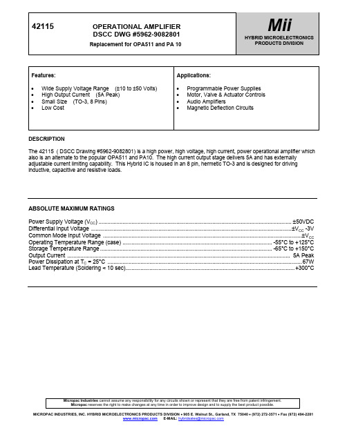
Micropac Industries cannot assume any responsibility for any circuits shown or represent that they are free from patent infringement. Micropac reserves the right to make changes at any time in order to improve design and to supply the best product possible.
ABSOLUTE MAXIMUM RATINGS
Power Supply Voltage (VCC) ................................................................................................................................. ±50VDC Differential Input Voltage ......................................................................................................................................±VCC -3V Common Mode Input Voltage .....................................................................................................................................±VCC Operating Temperature Range (case) .................................................................................................... -55°C to +125°C Storage Temperature Range ................................................................................................................... -65°C to +150°C Output Current ..................................................................................................................................................... 5A Peak Power Dissipation at TC = 25°C ..................................................................................................................................67W Lead Temperature (Soldering < 10 sec)................................................................................................................. +300°C
2SJ598中文资料
TOTAL POWER DISSIPATION vs. CASE TEMPERATURE 30
25
20
15
10
5
0 0 20 40 60 80 100 120 140 160 TC - Case Temperature - ˚C
ID - Drain Current - A
TC = 25˚C
Single Pulse –0.1
Body Diode Forward Voltage
VF(S-D) IF = 12 A, VGS = 0 V
Reverse Recovery Time
trr
IF = 12 A, VGS = 0 V
Reverse Recovery Charge
Qrr
di/dt = 100 A /µs
MIN.
–1.5 5
The information in this document is subject to change without notice. Before using this document, please
confirm that this is the latest version. Not all products and/or types are available in every country. Please check with an NEC Electronics sales representative for availability and additional information.
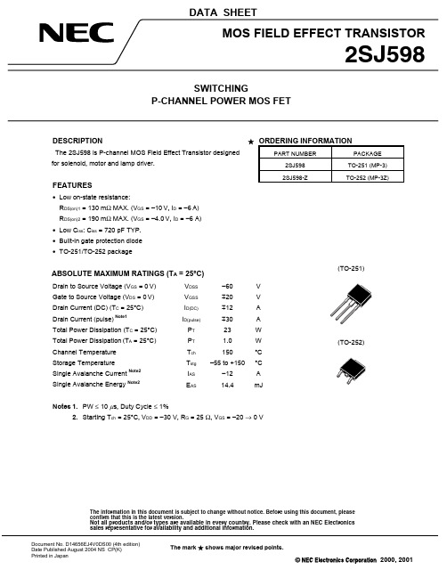
2SJ598
FORWARD TRANSFER CHARACTERISTICS –100
–10
–1
TA = −55˚C
Cat_PMC915 Technical Instruction-CH01
0 . 6 < cos ϕ < 1
频率 0.2Hz 0.1Hz 45-70Hz 电度量 1.0% 0-999,999,999 3.3 工作参数 工作电源:直流 85V-265V 或交流 80V-300V 工作温度:-5°C-+55°C 存储温度:-20°C-+80°C 通讯: MODBUS/ RS485 半双工接口 通讯速率:300/1200/2400/4800/9600/19200bps 可选 继电器输出:30VDC/10A 或 250VAC/10A, 电阻性或一般继电器线圈感性负载 频率:50/60Hz
ABB
负责部门 CNILX/TD 编 制 Karen Tao 日 期 14/8/2002 审 核 Patrick Zhang
技术文件 版 次 1 批 准 Gavin Xu
1TNC911104D2001 页次/总页数 1/9 产 品 ESD2000
PMC915 电力监测与控制装置技术说明书 目
1 2
录
3.1 标准 .................................................................... 4 3.2 测量技术指标 ............................................................ 5 3.3 工作参数 ................................................................ 5 4 安装 .................................................................... 5
概述 .................................................................... 2 功能简介 ................................................................ 2
2STR2215;中文规格书,Datasheet资料

c shows exceptional high gain performances du coupled with very low saturation voltage. Obsolete Pro The complementary NPN is the 2STR1215.
Date
Revision
Changes
09-Feb-2006
1
Initial release.
20-Jul-2006
2
New template.
08-Sep-2008
3
Updated the SOT-23 mechanical data.
Updated Figure 1: Internal schematic diagram
Produc hFE (1) DC current gain
IC = -50 mA VCE = -2 V 200
IC = -500 mA VCE = -2 V 200 280 560
IC = -1 A IC = -2 A
VCE = -2 V 130 VCE = -2 V 80
leteCCBO
Collector-base capacitance (IE = 0)
IEBO
(IC =0)
VEB = -4 V
-0.1 µA
) Collector-base
t(s V(BR)CBO breakdown voltage
IC = -100 µA
-15
V
c (IE = 0)
rodu V(BR)CEO (1)
Collector-emitter breakdown voltage
IC915使用说明书

关键词:应`ELIWELL`温控器IC915PTC12V应`ELIWELL`温控器IC915PTC12V温度控制器IC901、IC902、IC912、IC915、ID961、ID971、ID974、ID985LX、EWCM400、EWCM800、EWCM900、EWCM9000、EWLP120、EWPC915/T、TIC2CWC300、EWPC901/N湿度控制器IC912/R、IC915/R、EWHS280、EWHS、300 EWHS310压力控制器IC912/P、IC915/P、EWPA007、EWPA030、MICTECHIC912/P/R/V-I单输出数显控制器感谢您选用IC912/P/R/V-I产品。
在正式安装使用产品前,请认真仔细地阅读本产品说明书。
请妥善保存此中文产品说明书,以备将来使用。
中文产品说明书是在意大利生产商提供的英文产品说明书的基础上制作的,在实际使用产品时,对此中文说明书若有疑问,请参考英文产品说明书。
输出IC912具有1个开关量输出,用户可以很方便地设定输出的工作是加湿(增压)/去湿(降压)。
举例说明:SP1=20.0%rH、dF1=2.5%rH、HC1=去湿,当湿度≥22.5%rH(SP1+dF1)时,输出工作,当湿度回复到20.0%rH时,输出停止工作;设定点的设定设定点设定步骤如下:1.在仪表显示当前测量值时,按仪表面板上的SET键,仪表将显示SP1。
2.此时按SET键,可以看到当前设定值。
3.再按︽键或︾键,可以改变设定值。
4.按fnc键,仪表将恢复显示传感器测量值,从设定过程中退出。
在设定SP1的过程中,仪表面板上方最右侧的小灯一直亮起,表明仪表正处于设定过程中。
参数设置IC912将所有的参数按对象与功能分类放置在4个参数卷中:rE1、diS、CnF、FPr,进入参数卷的方法如下所列:1.在仪表显示当前传感器测量值时,持续按仪表面板上的SET键至少5秒钟,仪表将显示第一个参数卷代码rE1。
CRE6959VH-S2中文规格书PDF资料
VTH_OCP(V)
VTH_OFF(V)
I_ST(uA)
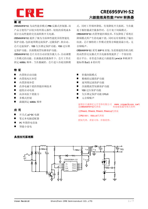
CRE6959VH‐S2
六级能效高性能 PWM 转换器
I_ST(uA) VS Temperature 10
8
6
4
2
0 ‐40 ‐10
20 50 80 Temperature(℃)
110 140
VTH_OFF(V) VS Temperature 8.5
0.05
0º
8º
Vrsion: Rev16.10
ShenZhen CRE Semiconduct CO.,LTD
7/7
推荐条件 VDD 最高工作电压 结温范围 环境温度范围
参考范围 -0.3—80 -0.3—6 -0.3—6
≤650 180 260 0-125 -65--150
单位 V V V V
℃/W ℃ ℃ ℃
80V -40℃-125℃ -40℃-85℃
Vrsion: Rev16.10
ShenZhen CRE Semiconduct CO.,LTD
Drain Drain Drain Drain
管脚功能描述 反馈引脚,接光耦反馈 大电流输出和检测端 电源 地 内置高压 Mos 管漏极 内置高压 Mos 管漏极 内置高压 Mos 管漏极 内置高压 Mos 管漏极
绝对最大额定值
参数 VDD FB CS DRAIN 封装热阻 接合点温度(10 秒) 工作温度范围 储存温度范围
IOTP(uA)
CRE6959VH‐S2
六级能效高性能 PWM 转换器
IOTP(uA) VS Temperature
110.00 108.00 106.00 104.00 102.00 100.00
2SC2235中文资料(toshiba)中文数据手册「EasyDatasheet - 矽搜」
芯片中文手册,看全文,戳
东芝晶体管
音频功率放大器应用 驱动级放大器的应用
硅NPN外延型(厘进程)
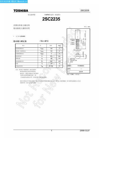
2SC2235
2SC2235
单位:mm
• 为了补充2SA965.
绝对最大额定值
(TA = 25°C)
特点
符
评级
Unit
集电极基极电压
集电极 - 发射极电压
发射极基极电压 集电极电流 基极电流 集电极耗散功率 结温 存储温度范围
100 ms*
10 ms*
50
30 Collector current I
*: Single nonrepetitive 10
pulse Ta = 25°C
5 Curves must be derated
3 linearly with increase in
LinkSwitch-II产品系列应用指南说明书
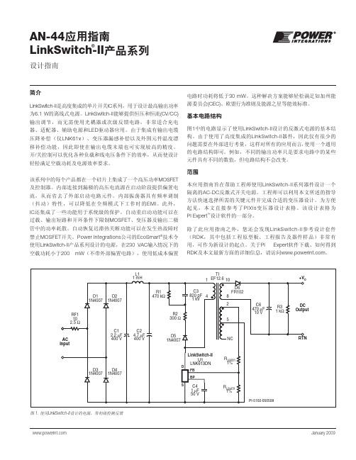
AN-44应用指南LinkSwitch-II 产品系列 January 2009设计指南®简介LinkSwitch-II 是高度集成的单片开关IC 系列,用于设计最高输出功率 为6.1 W 的离线式电源。
LinkSwitch-II 能够提供恒压和恒流(CV/CC) 输出调节,而无需使用光耦器或次级反馈电路,非常适合充电器、适配器、辅助电源和LED 驱动器应用。
由于集成有输出电缆压降补偿(仅LNK61x )、变压器漏感补偿以及外围元件温度漂移补偿功能,因此即使在输出电缆末端也可实现较高的精度。
开/关控制可以优化各种负载和线电压条件下的效率,从而使设计轻松满足空载功耗及电源效率要求。
该系列中的每个产品都在一个硅片上集成了一个高压功率MOSFET 及控制器。
内部连接到漏极的高压电流源在启动阶段提供偏置电流,从而省去了外部启动电路元件。
内部振荡器具有频率调制 (抖动)特性,可以降低在全频模式下工作时的EMI 。
此外,IC 还集成了一些功能用于系统级的保护。
自动重启动功能可以在过载、输出短路和开环条件下限制MOSFET 、变压器及输出二极管中的功率耗散。
自动恢复迟滞热关断功能可以在发生热故障时禁止MOSFET 开关。
Power Integrations 公司的EcoSmart ®技术令使用LinkSwitch-II 产品系列设计的电源,在230 VAC 输入情况下的空载功耗小于200 mW (不带外部偏置电路),使用低成本偏置电路时功耗将低于30 mW 。
这种解决方案能够轻松满足如加州能源委员会(CEC)、欧盟行为准则及能源之星等能效标准。
基本电路结构图1中的电路显示了使用LinkSwitch-II 设计的反激式电源的基本结构。
由于使用了高度集成的LinkSwitch-II 器件,因此仅有很少的问题需要在外部进行考量,这样对所有的应用而言,使用一个通用的电路结构即可。
例如,不同的输出功率只是要求电路中的某些元件具有不同的数值,但电路结构不会改变。
L5-STUDIO用户手册(中文)说明书

简介在英国非常自豪的设计,工程和制造.狮心王(Lionheart)系列带来精品的单端或并联单端的甲类电子管音调提供给独具慧眼的演奏家,正是他们一直在寻找的一种独特的灵敏的具有英国特色电子管音调.L5-STUDIO是5W 甲类单端输出级渗出经典,温暖的电子管色调。
你驱动得越重,听起来就越好。
加上有足够的增益为现代的音调,它也有凶猛、侵略性的一面,使它适合任何风格的玩家. 完美的用于工作室和实践使用(使用5W或0.5W输出),但同样适合在室内舞台上插入兰尼LT112、LT212或L412机柜。
这声音会让你大吃一惊。
利用在IRT-Studio中首次发布的T-USB技术,L5-STUDIO让你能够以一种前所未有的方式将电子管的色调和数字灵活的结合在一起,这对于那些在以前寻找复古美学,伟大的电子管音色与现代功能相结合的玩家来说是不可能的。
每一款 狮心王 Lionheart产品都是由经验丰富的吉他手进行广泛的演奏测试,然后才发货给我们的客户。
只有当设备完成到我们完全满意时,它才被分配到自己的独特的建造编号,然后手工敲击在后面安装的铭牌上。
你的L5-STUDIO应该给你多年的无故障放大,然而,请花时间阅读本手册和熟悉自己的控制,因为它将允许你得到最好的放大器。
我们希望您喜欢使用您的L5-STUDIO,就像我们喜欢设计和制作它一样。
来自全体LANEY成员的最美好的祝福。
高输入:“HI”代表高增益。
这种输入是为低输出电平吉他的连接而设计的,使它非常适合单线圈和低增益双线圈型拾音器。
在这个输入中使用高增益拾取可能会使驱动前置放大器太硬,造成“模糊”的声音。
只能使用优质的吉他电缆. 低输入:“LO”代表低增益。
这种输入从高输入衰减了大约50%,是为高输出电平吉他设计的。
它对于从高增益双线圈型拾音器获得“紧密”而不是“糊状”的输出非常有用。
也使用这个输入为最干净的全范围的声音与扩展低端响应。
只能使用优质的吉他电缆.清音音量:设置清音通道的响度。
LXXLD15 友顺UTC 电子元器件芯片
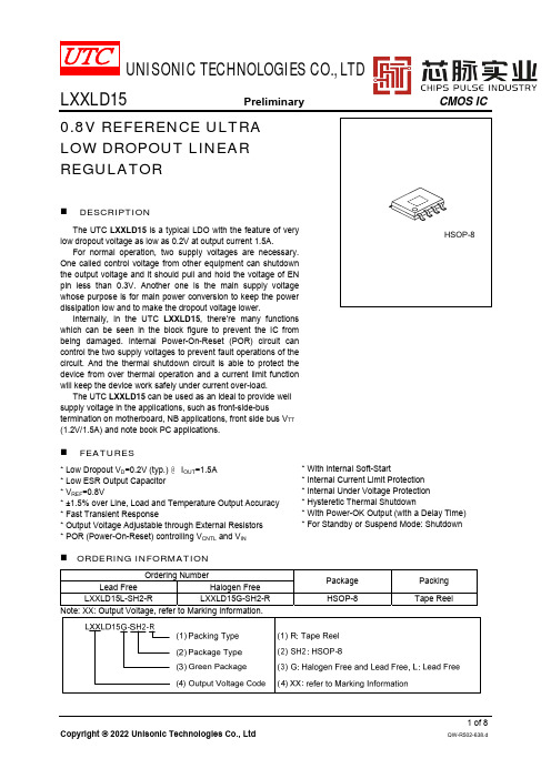
UNISONIC TECHNOLOGIES CO., LTDLXXLD15Preliminary CMOS IC0.8V REFERENCE ULTRALOW DROPOUT LINEARREGULATOR⏹DESCRIPTIONThe UTC LXXLD15 is a typical LDO with the feature of verylow dropout voltage as low as 0.2V at output current 1.5A.For normal operation, two supply voltages are necessary.One called control voltage from other equipment can shutdownthe output voltage and it should pull and hold the voltage of ENpin less than 0.3V. Another one is the main supply voltagewhose purpose is for main power conversion to keep the powerdissipation low and to make the dropout voltage lower.Internally, in the UTC LXXLD15, there’re many functionswhich can be seen in the block figure to prevent the IC frombeing damaged. Internal Power-On-Reset (POR) circuit cancontrol the two supply voltages to prevent fault operations of thecircuit. And the thermal shutdown circuit is able to protect thedevice from over thermal operation and a current limit functionwill keep the device work safely under current over-load.The UTC LXXLD15 can be used as an ideal to provide wellsupply voltage in the applications, such as front-side-bustermination on motherboard, NB applications, front side bus V TT(1.2V/1.5A) and note book PC applications.⏹FEATURES*Low Dropout V D=0.2V (typ.) @ I OUT=1.5A*Low ESR Output Capacitor*V REF=0.8V*±1.5% over Line, Load and Temperature Output Accuracy *Fast Transient Response*Output Voltage Adjustable through External Resistors*POR (Power-On-Reset) controlling V CNTL and V IN *With internal Soft-Start*Internal Current Limit Protection*Internal Under Voltage Protection*Hysteretic Thermal Shutdown*With Power-OK Output (with a Delay Time) *For Standby or Suspend Mode: Shutdown⏹ORDERING INFORMATIONOrdering NumberPackage Packing Lead Free Halogen FreeLXXLD15L-SH2-R LXXLD15G-SH2-R HSOP-8TapeReel⏹MARKING INFORMATION⏹PIN CONFIGURATIONV INGND FB V OUT V OUTV INV CNTL P OK EN ⏹PIN DESCRIPTIONDESCRIPTION There’s an external resistor divider connected to this pin which is necessary to give the feedback voltage to the regulator. The external circuit is combined as the and FB is R1(connected with a bypass capacitor which can improve the load transient response),and between FB and ground is R2.The valueof R2 and R1 are recommended between 100Ω~10k .So the output voltage is The output voltage pin of the regulator. There should be set an output capacitor to compensate for closed-loop and also to improve transient responses. It’s necessary to connect Pin 3 and Pin 4 together by wide tracks. It’s necessary to connect the Exposed Pad and V voltage. Monitoring this pin’s voltage can reset Power-On.Power input pin of the control circuitry. Connecting this pin to a +5V(recommended) supply voltage provides the bias for the control circuitry. Thevoltage at this pin is monitored for Power-On Reset purpose.BLOCK DIAGRAM⏹ABSOLUTE MAXIMUM RATINGPARAMETER SYMBOL RATINGS UNIT Supply Voltage (V CNTL to GND) V CNTL-0.3 ~ +7V Supply Voltage (V IN to GND) V IN-0.3 ~ +3.9VEN and FB to GND V I/O-0.3 ~ V CNTL+0.3VPOK to GND V POK-0.3 ~ +7V Power Dissipation P D 2.8WLead Soldering Temperature, 10 Seconds T SDR260°СJunction Temperature T J+150°СStorage Temperature T STG-65 ~ +150°СNote: Absolute maximum ratings are those values beyond which the device could be permanently damaged.Absolute maximum ratings are stress ratings only and functional device operation is not implied.⏹RECOMMENDED OPERATING CONDITIONSPARAMETER SYMBOL RATINGS UNIT Supply Voltage Control V CNTL 3.1 ~ 6 V Supply Voltage Input V IN 1.1 ~ 3.5 VOutput Voltage V CNTL=3.3±5%V OUT0.8 ~ 1.2 V V CNTL=5.0±5% 0.8 ~ V IN-0.2VOutput Current I OUT0 ~ 1.5 A Junction Temperature T J-40 ~ +125°С⏹THERMAL CHARACTERISTICSPARAMETER SYMBOL RATINGS UNIT Junction to Ambient in Free Air (Note 1) θJA44°C/W Junction to Case (Note 2) θJC19°C/W Notes: 1. θJA is measured with the component mounted on a high effective thermal conductivity test board in free air.The exposed pad of HSOP-8 is soldered directly on the PCB.2.The Thermal Pad Temperature is measured on the PCB copper area connected to the thermal pad ofpackage.ELECTRICAL CHARACTERISTICS(Refer to the typical application circuit. These specifications apply over, V CNTL = 5V, V IN = 1.5V, V OUT = 1.2V andAPPLICATION INFORMATION1.Power SequencingWhen there’s no main voltage applied at V IN, it is suggested not to apply a voltage to V OUT for a long time. Because the internal parasitic diode (between V OUT to V IN) will conduct and dissipate power, there’s no protection.2.Output CapacitorA proper output capacitor to maintain stability and improve transient response over temperature and current is necessary. Proper ESR (equivalent series resistance) and capacitance of the output capacitor should be selected properly for stability of the normal operation and good load transient response.Many kinds of capacitors can be used as an output capacitor, such as ultra-low-ESR capacitors (like ceramic chip capacitors), low-ESR bulk capacitors (like solid Tantalum, POSCap, and Aluminum electrolytic capacitors). And also the value of the output capacitors’ can be increased without limit.In the applications with large stepping load current, the low-ESR bulk capacitors are normally recommended. Decoupling ceramic capacitors are recommended to be placed at the load and ground pins very closely and also the impedance of the layout must be minimized.3.Input CapacitorIn order to prevent the input rail from dropping, the proper input capacitor to supply current surge during stepping load transients is required. Because the limited slew rate of the surge currents, more parasitic inductance needs more input capacitance.Ultra-low-ESR capacitors (>100mF, ESR<300mW) is recommended for the input capacitor.4.Feedback NetworkThe following figure shows the feedback network between V OUT GND and FB pins. Working with the internal error amplifier, the feedback network can provide proper frequency response for the UTC LXXLD15.V OUTTYPICAL APPLICATION CIRCUITS ing an Output Capacitor with ESR≥18mΩing an MLCC as the Output CapacitorUTCLXXLD15POKENEnablePOKENGNDFBOUTOUTVV CNTLR3=1kΩR2=78kR1=39kΩOUT=22µFV OUT+1.2V/1.5AV IN+1.5VCNTL=1µFC IN=22µF=56pFV CNTL+5V5678V OUT (V) R1 (kΩ)R2(kΩ)C1(pF)1.0543137.6471.52730.86821.81512150。
2.7W双声道立体音频放大器
2.7W双声道立体音频放大器概述4985SD是一款双通道桥接的音频功率放大器,在5V电源电压4Ω负载时,可提供2.7W的功率。
具有低功耗关断模式和过温保护功能。
在电路启动时,具有缓冲及防抖动功能。
功能特点l缓冲及防抖动l过温保护l低功耗关断模式l PO为1% THD+N, VDD = 5VRL=4Ω 2.2W(typ)RL=8Ω 1.4W(typ)l PO为10% THD+N, VDD = 5VRL=4Ω 2.7W(typ)RL=8Ω 1.7W(typ)l PO为1% THD+N, VDD = 4VRL=4Ω 1.4W(typ)RL=8Ω0.88W(typ)l关断电流0.04μA(typ)l工作电压范围 2.7V~5.5Vl封装方式:DIP16(4985SD)用途l手机、PDA、MP4、PMPl手提电脑l桌面音响设备l多媒体显示器管脚排列图管脚说明功能框图功能说明桥接参数说明4985SD由两对运算放大器组成双通道(通道A和通道B)立体声放大器。
外接反馈电阻R2,R4和输入电阻R1,R3决定了放大器A(-out)和B(-out)的闭环增益,同时内建20K电阻使放大器A的(+out)和B的(-out)端的增益为1。
4985SD所驱动的负载接在两放大器的输出端-OUTA和+OUTA之间。
放大器A的(-out)端就是放大器A的(+out)端的输入端,这就使两个输出端产生的信号有180°的相位差,利用这个相位差,桥接模式下的增益为:A VD=2*(Rf/Ri)或者A VD=2*(R2/R1)桥接模式比单端模式更有优势。
在桥接模式下,差分输出使增益翻倍,它的输出功率是相同情况下单端模式的4倍。
桥接模式的另一个优势是在负载上没有直流电压。
输出信号由通道A和B偏置在VDD/2。
所以它无需在单端模式下的耦合电容。
在单端输出模式下,如果不使用输出耦合电容,就会在负载上产生一个VDD/2的直流偏置电压,这就会增加芯片的功耗并对负载造成永久性的损害。
LumeroTel-915 使用说明书
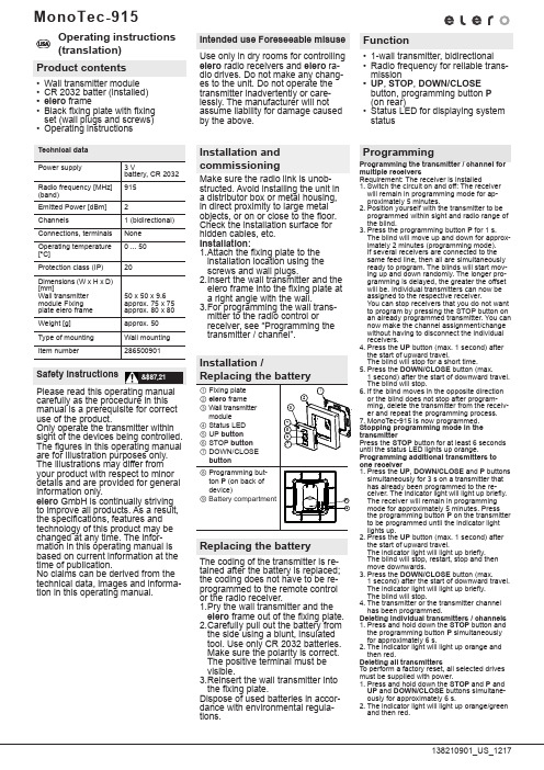
Deleting all A-12 Technical A-13 A-13 Battery A-13 A-13 General declaration of A-13U SAManual/Automatic control lightbutton Pv UP buttonySTOP buttonb DOWN buttonBatterycompartment This equipment has been tested and found to comply with the limits for a class B digital device,pursuant to part 15 of the FCC Rules.These limits are designed to provide reasonable protection against harmful interference in a residential installation.Thisequipment generates,uses and can radiate radio frequency energy and if not installed and used in accordance with the instructions,may cause harmful interference to radio communications.However,there is no guarantee that interference will not occur in a particular installation.If this equipment does cause harmful interference to radio or television reception,which can be determined by turning the equipment off and on,the user is encouraged to try to correct the interference by one or more of the following measures:•Reorient or relocate the receiving antenna.•Increase the separation between the equipment and receiver.•Connect the equipment into an outlet on a circuit different from that to which the receiver is connected.•Consult the dealer or an experienced radio/TV technician for help.Operation with non-approved equipment is likely to result ininterference to radio and TV reception.The user is cautioned that changes and modifications made to the equipment without the approval of manufacturer could void the user's authority to operate this equipment.U SANote:Radio base stations transmitting in the same frequency range may cause reception interference.Please note that the operating range of the radio signal is limited by legislation as well as by the product design.Wall holder installation• Before installing the wall holder,always ensure that the transmitter and receiver are in proper working order.• Mount the holder onto the wall using the two raw plugs and screws provided.General informationThe LumeroTel-915 handheld transmitter can be used to operate one or more receivers.This device is characterised by its user-friendly operation.Designated useThe LumeroTel-915 device may be used to operate roller shutters/sun protection systems only .• Please note that radio-controlled systems may not be used in areas with a high risk of interference (e.g.hospitals,airports).• The remote control is intended solely for use with equipment and systems in which malfunctions in the handheldtransmitter or receiver would not pose any risk to persons,animals or property or which contain safety devices to eliminate such risks.• The operator is not protected from interference from other telecommunications systems and terminal equipment(e.g.even from radio-controlled systems which are properly operated in the same frequency range).• Radio receivers may only be used in combination with equipment and systems stipulated in manufacturers’specifications.U S AProgramming transmitter/channelPrerequisite:The receiver must be installed.1.With pre-installed electric receivers,the fuse must bedisconnected and reconnected after a few seconds.The receiver will remain in programming mode for approximately 5 minutes.2.Position yourself in front of the roller shutter/awning/blind with the remote control in your hand.3.Open the front cover of the device and press the transmitter pro-gramming button P briefly .The shutter/awning/blind will start to move up and down.This will happen for approximately 2 minutes.4.To define the keyboard layout,press the UP button on the trans-mitter as soon as the shutter/awning/blind begins to move upwards (after approx.1 second).The shutter/awning/blind will come to a halt briefly.As soon as the shutter/awning/blind begins to move again,press the DOWN button on the handheld transmitter.The shutter/awning/blind will come to a stop.The transmitter or this channel has been successfully programmed.Programming additional transmittersTo programme additional transmitters in one receiver,please proceed as follows:1.Press the UP,DOWN and programming button P on a transmitter that has already been programmed in the receiver until the LED goes out.2.To define the keyboard layout,press the UP button on the handheld transmitter as soon as the shutter/awning/blind begins to move upwards (after approx.1 second).The shutter/awning/blind will come to a halt briefly.As soon as the shutter/awning/blind begins to move again,press the DOWN button on the handheld transmitter.The shutter/awning/blind will come to a stop.The transmitter or this channel has been successfully programmed.Manual/Automatic sliding switchThe sliding switch is used to switch the receivers into either manual or automatic mode.When the sliding switch is set to automatic mode,thereceivers will respond to every signal transmitted,whereas in manual mode they will only respond to UP,STOP and DOWN control commands,as well as to wind alarm signals.Transmission control lightThe transmission control light is illuminated when a radio signal is being transmitted.The transmission control light will flash during transmission if battery power is low.The transmission power or radio operating range will decrease as battery power decreases.If the transmission control light does not light up when the buttons are pressed,the batteries must be replaced.Group controlGroup control refers to the operation of one or more receivers at the same time.The group selected is controlled via a control command.The LumeroTel-915 operates the chosen group via a radio channel.Note:The inlay card beneath the transparent cover can beused to make a note of the groups which have been programmed.position,press the STOP button in addition.The curtain/canopy/blind will come to a stop.The intermediate position has been successfully programmed. Programming Pos VPrerequisite:The transmitter has been programmed and the end limit positions have been set.The curtain/canopy/blind is in the lower end limit position.1.Move the curtain/canopy/blind in the UP direction using the handheld transmitter until the ventilation slits are open or the reverse position has been reached.Note:Keep the UP button pressed until the desired position is reached.2.When the curtain/canopy/blind has reached the desired position,press the STOP button in addition.The curtain/canopy/blind will come to a stop.The venti-lation/reverse position has been successfully programmed.U S AOperating voltage 3 V DC Battery requirements 2 x LR 03 (AAA)System of protectionIP 20Permissible ambient temperature –10 to +55 °C Operating frequency 915,3 MHz Dimensions in mmL 121 x W 43 x H 23Deleting individual transmittersDisconnect the fuse – and reconnect after a few seconds.1.Open the front cover on the device and press the following buttons simultaneously :• Programming button P • STOP button2.Keep these two buttons pressed until the LED goes out briefly.Deleting all transmittersDisconnect the fuse – and reconnect after a few seconds.1.Open the front cover on the device and press the following buttons simultaneously :• Programming button P • UP button • STOP button • DOWN button2.Keep these buttons pressed until the LED flashes 3 times.Technical data The maximum radio operating range is 25 m indoors and 350 m outdoors.Adjustment to Pos BPrerequisite:The transmitter has been programmed.1.Press the UP button twice in quick succession .2.The drive will adjust the curtain/canopy/blind into the stored intermediate position.If no intermediate position is stored,the curtain/canopy/blind is automatically adjusted into the lower limit position.Adjustment to Pos V (roller shutter,awning)Prerequisite:The transmitter has been programmed.1.Press the UP button twice in quick succession .2.The curtain/canopy is adjusted into the stored ventilationposition.If no ventilation position is stored,the curtain/canopy is automatically adjusted into the upper limit position.Adjustment to Pos V (venetian blind)Prerequisite:The transmitter has been programmed.1.Press the UP button twice in quick succession .2.The blind is adjusted into the stored reverse position.If no reverse position is stored,the blind is automatically adjusted into the lower limit position.Deleting Pos B1.Press the following buttons simultaneously :• DOWN button • STOP button2.Keep these two buttons pressed until the LED goes out briefly.Deleting Pos V1.Press the following buttons simultaneously :• UP button • STOP button2.Keep these two buttons pressed until the LED goes out briefly.Clean the device with a damp cloth only.Do not use a cleansing agent as doing so may damage the plastic.TroubleshootingGeneral declaration of conformity:The company elero GmbH hereby declares that the LumeroTel-915 handheld transmitter complies with the basic requirements and other relevant regulations of the EC Directive 1999/5/EG.。
JBL PRX915 15英寸有力音箱说明书
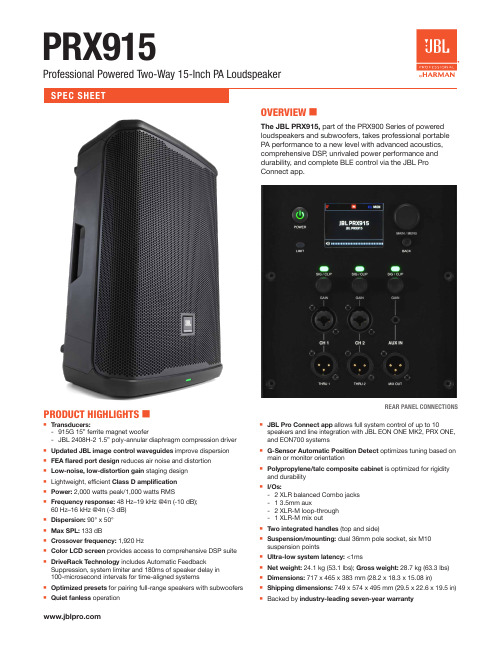
9 Net weight: 24.1 kg (53.1 lbs); Gross weight: 28.7 kg (63.3 lbs)
9 Dimensions: 717 x 465 x 383 mm (28.2 x 18.3 x 15.08 in)
PRODUCT HIGHLIGHTS 6
9 Transducers: - 915G 15” ferrite magnet woofer - JBL 2408H-2 1.5” poly-annular diaphragm compression driver
9 Updated JBL image control waveguides improve dispersion 9 FEA flared port design reduces air noise and distortion 9 Low-noise, low-distortion gain staging design 9 Lightweight, efficient Class D amplification 9 Power: 2,000 watts peak/1,000 watts RMS 9 Frequency response: 48 Hz–19 kHz @4π (-10 dB);
Dial In Your Sound With Class-Leading DSP PRX915 is fully loaded with comprehensive DSP, all accessible via the JBL Pro Connect app and onboard full-color LCD. Processing
MonoTec-915使用说明书
MonoTec-915Operating instructions (translation)Product contents• Wall transmitter module • CR 2032 batter (installed) • elero frame• Black fixing plate with fixing set (wall plugs and screws) •Operating instructionsSafety instructionsPlease read this operating manual carefully as the procedure in this manual is a prerequisite for correct use of the product.Only operate the transmitter within sight of the devices being controlled. The figures in this operating manual are for illustration purposes only. The illustrations may differ from your product with respect to minor details and are provided for general information only.elero GmbH is continually striving to improve all products. As a result, the specifications, features and technology of this product may be changed at any time. The infor -mation in this operating manual is based on current information at the time of publication.No claims can be derived from the technical data, images and informa -tion in this operating manual.&$87,21Intended use Foreseeable misuse Use only in dry rooms for controlling elero radio receivers and elero ra-dio drives. Do not make any chang -es to the unit. Do not operate the transmitter inadvertently or care -lessly. The manufacturer will not assume liability for damage caused by the above.Function• 1-wall transmitter, bidirectional • Radio frequency for reliable trans -mission• UP , STOP , DOWN/CLOSE button, programming button P (on rear)• Status LED for displaying system statusInstallation and commissioningMake sure the radio link is unob -structed. Avoid installing the unit in a distributor box or metal housing, in direct proximity to large metal objects, or on or close to the floor. Check the installation surface for hidden cables, etc. Installation: 1. A ttach the fixing plate to the installation location using the screws and wall plugs. 2. I nsert the wall transmitter and the elero frame into the fixing plate at a right angle with the wall. 3. F or programming the wall trans -mitter to the radio control or receiver, see “Programming the transmitter / channel”.ProgrammingProgramming the transmitter / channel for multiple receiversRequirement: The receiver is installed1. Switch the circuit on and off: The receiver will remain in programming mode for ap -proximately 5 minutes.2. Position yourself with the transmitter to be programmed within sight and radio range of the blind.3. Press the programming button P for 1 s. The blind will move up and down for approx -imately 2 minutes (programming mode). If several receivers are connected to the same feed line, then all are simultaneously ready to program. The blinds will start mov -ing up and down randomly. The longer pro -gramming is delayed, the greater the offset will be. Individual transmitters can now be assigned to the respective receiver.You can stop receivers that you do not want to program by pressing the STOP button on an already programmed transmitter. You can now make the channel assignment/change without having to disconnect the individual receivers.4. Press the UP button (max. 1 second) after the start of upward travel.The blind will stop for a short time.5. Press the DOWN/CLOSE button (max.1 second) after the start of downward travel. The blind will stop.6. If the blind moves in the opposite direction or the blind does not stop after program -ming, delete the transmitter from the receiv -er and repeat the programming process.7. MonoTec-915 is now programmed. Stopping programming mode in the transmitterPress the STOP button for at least 6 seconds until the status LED lights up orange.Programming additional transmitters to one receiver1. Press the UP , DOWN/CLOSE and P buttons simultaneously for 3 s on a transmitter that has already been programmed to the re -ceiver. The indicator light will light up briefly. The receiver will remain in programming mode for approximately 5 minutes. Press the programming button P on the transmitter to be programmed until the indicator light lights up.2. Press the UP button (max. 1 second) after the start of upward travel.The indicator light will light up briefly. The blind will stop, restart, stop and then move downwards.3. Press the DOWN/CLOSE button (max.1 second) after the start of downward travel. The indicator light will light up briefly. The blind will stop.4. The transmitter or the transmitter channel has been programmed.Deleting individual transmitters / channels 1. Press and hold down the STOP button and the programming button P simultaneously for approximately 6 s.2. The indicator light will light up orange and then red.Deleting all transmittersTo perform a factory reset, all selected drives must be supplied with power.1. Press and hold down the STOP and P and UP and DOWN/CLOSE buttons simultane-ously for approximately 6 s.2. The indicator light will light up orange/green and then red.Replacing the batteryThe coding of the transmitter is re -tained after the battery is replaced; the coding does not have to be re -programmed to the remote control or the radio receiver. 1. P ry the wall transmitter and the elero frame out of the fixing plate. 2. C arefully pull out the battery from the side using a blunt, insulated tool. Use only CR 2032 batteries. Make sure the polarity is correct. The positive terminal must be visible. 3. R einsert the wall transmitter into the fixing plate.Dispose of used batteries in accor -dance with environmental regula -tions.DisposalBatteries and old units may not be disposed of with household waste. 1. D ispose of packaging in the recy -cling bin for cardboard and paper. 2. D ispose of old batteries in the recycling bin for used batteries or have a retailer recycle them. 3. D ispose of old units at an elec -tronic waste recycling facility or have a retailer recycle them.Conformityelero hereby declares that Mono -Tec-915 wall transmitter is in com -pliance with Directive 2014/53/EU. The full text of the EU Declaration of Conformity is available at the following Internet address:www.elero.de/downloads-service/Service /manufacturer's addressIf malfunctions have occurred or the device has been damaged despite proper handling, contact your con -tractor or dealer. elero GmbH73278 Schlierbach GERMANYwww.elero.deNotes on troubleshootingRepairPlease specify the item number, item description, type of fault, situ -ational circumstances, presumed cause, unusual events prior to the problem.CleaningClean the device with a damp cloth only. Do not use cleaning agents be -cause they can damage the plastic.WarrantyWithin the legal warranty period, we will remedy any defects caused by material or manufacturing defects by repairing or replacing the unit. Unauthorised modifications will void the warranty.Synchronised programming modeFor programming one transmitter to multiple receivers at the same time. 1. P ress the DOWN/CLOSE buttons and the programming button P simultaneously for 3 s on a trans -mitter that has already been pro -grammed to the receiver. The sta -tus LED flashes orange and green multiple times. The receivers are now in programming mode. 2. P erform steps 2 to 7 under “Pro -gramming the transmitter / channel” with the transmitter to be pro -grammed.Configuring the driveProgramming the intermediate position Requirement:The blind is in the upper end position.1. Press the DOWN/CLOSE button until the desired intermediate position is reached.2. Additionally press the STOP button. The blind will stop. The intermediate position has now been stored.Programming the ventilation / tilting / fabric tautening positions Requirement:The blind is in the lower end position. 1. Press the UP button until the louvres open, the venetian blind slats are tilted or the awning fabric is taut.2. Additionally press the STOP button.The blind will stop. The ventilation / tilting / fabric tautening position has been stored. Moving to the intermediate position Requirement:The intermediate position has been programmed.1. Press the DOWN/CLOSE button twice quickly. The blind will move to the stored intermediate position.If no intermediate position has been pro -grammed, the blind will move to the lower end position.Important: If you are using venetian blinds and a programmed tilt position, the venetian blind slats will also tilt.If no tilt position has been preprogrammed, the blind will stop at the intermediate position with closed slats.Moving to the ventilation / tilting / fabric tautening positions Requirement:The ventilation / tilting / fabric tautening position has been programmed.1. Press the UP button twice quickly.The blind will move to the stored position. If no ventilation / tilting / fabric tauteningposition has been programmed, the blind will travel to the upper end position.You can also use a programmed hand-held transmitter to travel to the ventilation / tilting / fabric tautening position.Deleting the intermediate position Requirement: The transmitter is pro -grammed.1. Press and hold down the DOWN/CLOSE button and the STOP button simultaneous-ly for approximately 3 s.The intermediate position is now deleted. The indicator light will light up briefly.Deleting the ventilation position / tilting position / fabric tautening positionRequirement: The transmitter is programmed. 1. Press and hold down the UP button and the STOP button simultaneously for approximately.The ventilation / tilting / fabric tautening position has now been deleted.MonoTec-915FCC / ICFCC ID: YBU28650IC: 8929A- 28650USA (FCC)Part 15 Statement gem. FCC 15.19/RSS Gen Issue 3 Sect. 7.1.3This device (elero MonoTec-915) complies with Part 15 of the FCC Rules and with Industry Canada license-exempt RSS standard(s). Operation is subject to the following two conditions:(1) this device may not cause harmful interference, and(2) t his device must accept any interference received, including interference that may cause undesired operation. Canada, Industry Canada (IC)Le présent appareil (elero MonoTec-915) est conforme aux CNR d‘Industrie Canada applicables aux appareils ra-dio exempts de licence. L‘exploitation est autorisée aux deux conditions suivantes :(1) l‘appareil ne doit pas produire de brouillage, et(2) l‘utilisateur de l‘appareil doit accepter tout brouillage radioélectrique subi, même si le brouillage est susceptibled‘en compromettre le fonctionnement.Caution:Changes or modifications not expressly approved by the party responsible for compliance could void the user’s au-thority to operate the equipment.Information:This equipment has been tested and found to comply with the limits for a Class B digital device, pursuant to part15 of the FCC Rules. These limits are designed to provide reasonable protection against harmful interference in a residential installation. This equipment generates, uses and can radiate radio frequency energy and, if not installed and used in accordance with the instructions, may cause harmful interference to radio communications. However, there is no guarantee that interference will not occur in a particular installation. If this equipment does cause harmful interference to radio or television reception, which can be determined by turning the equipment off and on, the user is encouraged to try to correct the interference by one or more of the following measures:• Reorient or relocate the receiving antenna.• I ncrease the separation between the equipment and receiver.• C onnect the equipment into an outlet on a circuit different from that to which the receiver is connected.• C onsult the dealer or an experienced radio/ TV technician for help。
新版PYRO-915说明书
目录手册说明--------------------------------------------------------------------------------------------------- 2 安全指导--------------------------------------------------------------------------------------------------- 3 标志注解--------------------------------------------------------------------------------------------------- 3 介绍--------------------------------------------------------------------------------------------------------- 4 应用--------------------------------------------------------------------------------------------------------- 5 主要技术数据和特征--------------------------------------------------------------------------------- 5 运行条件------------------------------------------------------------------------------------------------ 5 附件设计和操作------------------------------------------------------------------------------------------ 6 外观和功能控制------------------------------------------------------------------------------------------ 7 运行前准备步骤------------------------------------------------------------------------------------------ 9 操作步骤--------------------------------------------------------------------------------------------------- 11 主要运行步骤------------------------------------------------------------------------------------------ 12 校准--------------------------------------------------------------------------------------------------- 12 获得校准点--------------------------------------------------------------------------------------- 12 绘制校准曲线------------------------------------------------------------------------------------ 12 测量步骤--------------------------------------------------------------------------------------------- 13 结果计算------------------------------------------------------------------------------------------ 13 维护--------------------------------------------------------------------------------------------------------- 14 储存规则--------------------------------------------------------------------------------------------------- 16 故障处理--------------------------------------------------------------------------------------------------- 16 附录--------------------------------------------------------------------------------------------------------- 17手册说明该手册能够帮助您熟悉PYRO-915+配件(以下特指该配件)的构造、运行原理、工作特征和运行环境。
- 1、下载文档前请自行甄别文档内容的完整性,平台不提供额外的编辑、内容补充、找答案等附加服务。
- 2、"仅部分预览"的文档,不可在线预览部分如存在完整性等问题,可反馈申请退款(可完整预览的文档不适用该条件!)。
- 3、如文档侵犯您的权益,请联系客服反馈,我们会尽快为您处理(人工客服工作时间:9:00-18:30)。
7;5A<6?@>?FEL<G B8I:?@D>G<B8M:EDI8:I ;8I8:E@B/IG=:5>07;6KF>27KF>26KF>28/Chmmhf ob^p0Onmebg^Ebf^glbhglEJIB@D<;@C<DH@EDH+L@G@D>;@8>G8C 8D;F:9E8G;B8MEJIUgbm?ffPDC LZrhnm 70Ghk ab`a bgknla ehZ]pbma ma^lm^Z]r2lmZm^\nkk^gm h_e^ll maZg 95B1ie^Zl^\ahhl^mri^J380Ug]^k ma^Zf[b^g\^pbma ]Zg`^khnl `Zl ebd^I 7S1SO 7hk NO 71pZla mb`am mri^bl k^\hff^g]^]@ie^Zl^m^lm ma^k^eZr bg k^Ze Ziieb\Zmbhgl3J_ma^Zf[b^g\^Zeehpl1]nlm ikhm^\m^]bl ik^_^k^gmbZeer k^\hff^g]^]390K F>bl Zg ^gobkhgf^gmZe _kb^g]er ikh]n\m3Pe^Zl^fZkdZ li^\bZe \h]^/:::0hk /::60pa^g hk]^kbg`3/::60lmZg]l RhIS \hfiebZgm pbma DZ]fbnf \hgmZ\m@/:::0lmZg]l _hk RhIS \hfiebZgm pbma DZ]fbnf2_k^^\hgmZ\m3DZ^Q]7W^e]bg`ib\mnk^l _hk KF>pbma mpblmbg`\hii^k pbk^3Pe^Zl^lahp p^e]bg`lmre^/B mh J 0Zg]ma^e^g`ma h_pbk^l pa^g hk]^kbg`3Pe^Zl^fZkdma^e^g`ma h_^Z\a pbk^_khf e^_m mh kb`am b_ma^e^g`ma bl ]b__^k^gm3/Chmmhf ob^p0H<I~OZY^NO^OWZ]Q*G<H<I~OZY^NO^Z[QY*SFTRFSFT SFTRFSFT Mhngmbg`T^kfbgZe Mhngmbg`T^kfbgZeMhngmbg`T^kfbgZe/\hgmZ\m \ehl^0/\hgmZ\m hi^g0/\hgmZ\m \ehl^0/\hgmZ\m hi^g0SFTRFSFT Mhngmbg`T^kfbgZe/\hgmZ\m \ehl^0/\hgmZ\m hi^g0SFTRFSFT Mhngmbg`T^kfbgZe/\hgmZ\m \ehl^0/\hgmZ\m hi^g0Mhngmbg`T^kfbgZe Mhngmbg`T^kfbgZeMhngmbg`T^kfbgZeH<I~OZY^NO^OWZ]Q*H<I~OZY^NO^OWZ]Q*H<I~OZY^NO^OWZ]Q*H<I~OZY^NO^Z[QY*H<I~OZY^NO^Z[QY*H<I~OZY^NO^Z[QY*KF>26KF>27KF>28KF>261R6KF>271R7KF>281R8KF>281R:KF>281R97;7Wbkbg`EbZ`kZf EJIB@D<;@C<DH@EDH+L@G@D>;@8>G8C 8D;F:9E8G;B8MEJIUgbm?ffPhlbmbo^iheZkbmrN^`Zmbo^iheZkbmrN^`Zmbo^iheZkbmr7;8=04/aA61RA;5501=05/aA71RA8550=06/aA61RA<5501=1-/aA71RA8:50=./aA61RA:5501=//aA71RA7:50=0/aA61RA:5501=1/aA71RA7:50=6/aA61RA8<501=.-/aA71RA6=:0=../aA61RA<5501=.//aA71RA8:50=.4/aA61RA;;501=.5/aA71RA8850=.6/aA61RA8;501=/-/aA71RA6=50=/2/aA61RA8=501=/3/aA71RA6>50=/4/aA61RA:5501=/5/aA71RA7:50=00/aA61RA95501=01/aA71RA7550=02/aA61RA;5501=03/aA71RA8550Smre^h_fZg`Zgbg langmDZ^Q]7Smre^G6mh G991ma^mab\dg^ll h_langm?aA6hk aA71R?k^lblmZg\^h_langm [^mp^^g B2C i v 1f 65,j=2=.0/aA61RA8>501=.1/aA71RA6>:0=/./aA61RA9:501=///aA71RA77:0=/6/aA61RA:5501=0-/aA71RA7:50=4/aA61RA8;501=5/aA71RA6=50=.2/aA61RA8:501=.3/aA71RA6<:0=/0/aA61RA:5501=/1/aA71RA7:50=0./aA61RA=5501=0//aA71RA9550EJIB@D<;@C<DH@EDH+L@G@D>;@8>G8C 8D;F:9E8G;B8MEJIUgbm?ffEbl\eZbf^kTabl ]ZmZla^^m bl _hk ma^\nlmhf^klx k^_^k^g\^3Bee ma^li^\b_b\Zmbhgl Zk^ln[c^\m mh \aZg`^pbmahnm ghmb\^3W^\hne]ghm ^oZenZm^Zee ma^i^k_hkfZg\^Zg]Zee ma^iZkZf^m^kl _hk ^o^kr ihllb[e^Ziieb\Zmbhg3Tanl ma^nl^k lahne][^bg Z kb`am ihlbmbhg mh \ahhl^ma^lnbmZ[e^ikh]n\m _hk ma^bk hpg Ziieb\Zmbhg3J_ma^k^bl Zgr jn^kr1ie^Zl^\hgmZ\m Ihg`_Z _hk ma^m^\agb\Ze l^kob\^3Ihp^o^k1bm bl ma^nl^kxl k^lihglb[bebmr mh ]^m^kfbg^pab\a ikh]n\m lahne][^nl^]hger3t XbZf^g Ihg`_Z Fe^\mkhZ\hnlmb\Dh31Lm]3Bee kb`aml h_Ihg`_Z Zk^k^l^ko^]37;9DZ^UOQ63R^eZr bl hg ma^yl^mz lmZmnl pa^g [^bg`k^e^Zl^]_khf lmh\d1pbma ma^\hglb]^kZmbhg h_lah\d kbl^g _khf mkZglbm Zg]k^eZr fhngmbg`1k^eZr phne][^\aZg`^]mh yk^l^mz lmZmnl1ma^k^_hk^1pa^g Ziieb\Zmbhg /\hgg^\mbg`ma^ihp^k lniier01ie^Zl^k^l^m ma^k^eZr mh yl^mz hk yk^l^mz lmZmnl hg k^jn^lm373Jg hk]^k mh fZbgmZbg yl^mz hk yk^l^mz lmZmnl1^g^k`bs^]ohemZ`^mh \hbe lahne]k^Z\a ma^kZm^]ohemZ`^1bfinel^pb]ma lahne][^:mbf^l fhk^maZg yl^mz hk yk^l^mz mbf^3Eh ghm ^g^k`bs^ohemZ`^mh yl^mz \hbe Zg]yk^l^mz \hbe lbfnemZg^hnler3Bg]Zelh ehg`^g^k`bs^]mbf^/fhk^maZg 6fbg0lahne][^Zohb]^]383Ta^m^kfbgZel h_k^eZr pbmahnm mpblm^]\hii^k pbk^\Zg ghm [^mbg2lhe]^k^]1\Zg ghm [^fho^]pbee_neer1fhk^ho^k mph m^kfbgZel \Zg ghm [^_bq^]Zm ma^lZf^mbf^3Smre^5:;k BAw937Smre^5:;26k BAw:37Smre^5<;k BAw937Smre^5<;26k BAw:37Smre^5<<k BAw937Smre^5<<26k BAw:37Smre^5<<27k BAw;37Dhgg^mhk lmre^Trib\Ze langm \hgg^\mbhg pZrlDZ^Q]7W^\Zg fZd^li^\bZe \hgg^\mbhg Z\\hk]bg`mh \nlmhkf^k.l k^jnbk^f^gm3Pe^Zl^ikhob]^nl pbmama^]kZpbg`1Zg]langm li^\b_b\Zmbhg Zg]\hgg^\mhk.l li^\b_b\Zmbbhg3GQXN\V760Jg \Zl^h_gh mhe^kZg\^lahpg bg hnmebg^]bf^glbhg?hnmebg^]bf^glbhg g 6ff1mhe^kZg\^lahne][^u537ff@hnmebg^]bf^glbhg l 6ffZg]g :ff1mhe^kZg\^lahne][^u538ff@hnmebg^]bf^glbhg l :ff1mhe^kZg\^lahne][^u539ff370Ta^mhe^kZg\^pbmahnm bg]b\Zmbg`_hk PDC eZrhnm bl ZepZrl u536ff3EJIB@D<;@C<DH@EDH+L@G@D>;@8>G8C 8D;F:9E8G;B8MEJIUgbm?ffSmre^h_fZg`Zgbg langmDZ^Q]7Smre^G6mh G991ma^mab\dg^ll h_langm?aA6hk aA71R?k^lblmZg\^h_langm [^mp^^g B2C i v 1f 65,j=1./aA61RA99501=1//aA71RA7750=10/aA61RA;5501=11/aA71RA8550。