Detection of Oil Slick Signatures in SAR Images by Fusion of
大副航海英语题库2501完全翻译版

[1]A cargo exception would appear onA. a Bill of Lading.B. the cargo manifest.C. the-Export Declaration.D. a Letter of Indemnity.Key: A 一个货物例外条款将出现在提货单上[2]A vessel emitting harmful substances into the air or spilling oil into the sea is aA: Polluter B. Emitter C. Spiller. D. OilerKey : A (光盘)船舶排放有害物质进入空气或溢出流入海中的石油是污染源[3]Antiseptics are used principally toA. speed-healingB. prevent infectionC. reduce inflammation.D. increase blood circulationKey: B (光盘)消毒剂主要用于防止感染[4]Any partial loss or damage shall be pro rata on the basis of such declared value.A. adjustedB. arrangedC. determinedD. fixedKey : A (光盘)任何部分的损伤或损害应根据这类声明的价值被按比例核算。
[5]At the time of ,you will be credited with two days' extra basic salary.A: paying-off B. signing off C. sending off D. going offKey: B 在签署解雇合同时,你将得到两天额外的基本工资。
参阅《劳务输出合同》第9条[6]Beams are cambered toA. increase their strengthB. provide drainage from the decksC. relievedeck stress D. All of the aboveKey: B 甲板横梁被制成弧型是方便甲板排水。
格拉尔德通风机操作指南说明书

Chapter 3 – Maintenance, Page 3-1Operator Cleaning and MaintenanceOverviewTo maintain the Gaylord Ventilator in good working order, and to keep the system operating at optimum efficiency, preventive maintenance, using the following schedule should be performed.Important Note: Ventilators incorporating UV Lamps require special maintenance as shown on Page 3-4. Some of the required maintenance on Ventilators with UV can be performed by the operator. However, direct exposure to UV light is hazardous to your skin and eyes and contact with live electrical components poses a significant risk of shock or death.Daily Cleaning and MaintenanceAt the end of the each cooking day, or at periodic intervals, depending upon the type of cooking, the XGS Extractors and Grease Drawer must be removed and cleaned. The Grease Gutter should also be wiped out. CAUTION: Before proceeding with cleaning, check to see that the exhaust fan is shut off and the cooking equipment is cool. To clean proceed as follows:1. Remove Extractors: CAUTION: Care should be taken when removing the Extractors, especially overfryers. It is recommended that the cooking equipment be cooled down and the fryers be covered prior to removing the Extractors. They may be removed by hand or by use of an optional Extractor Removal Tool (Refer to Figure 3-2-1). To remove, lift up slightly on the Extractor and pull out from the bottom, then straight down.2. The Extractors may be cleaned either by using a dishwasher or by soaking in a deep well sink using hotwater with a degreasing detergent, then scrubbed and rinsed. Gaylord Formula G-510EF detergent is highly recommended for this application. Refer to Page 3-7 for details.3. With the Extractors removed inspect the back wall and the underside of the exhaust plenum. If neces-sary clean with hot detergent water.4. Wipe and clean the Grease Gutter.5. Remove and empty the Grease Drawer, clean and replace.6. Replace the filters or Extractors. Note: Filters and Extractors must be installed with the openings run-ning vertical as shown in Figure 3-2-2. Gaylord XGS Extractors have an arrow stamped on the face designating “UP”.Additional Cleaning Instructions for UVi Series VentilatorsThe UV Lamps will develop a coating of dust, and sometimes debris that will have to be wiped away. The Lamps should be inspected weekly and cleaned when necessary. To clean proceed as follows:1. Remove all the Extractors.2. Reach up through the opening and carefully wipe each Lamp with a non abrasive wet cloth with milddetergent. Remove all the dust, grease or other contaminants that may have collected on the Lamp.3. Replace the Extractors.Note: Failure to maintain the cleanliness of the Lamps will reduce the UV systems ability to reduce the build-up of grease and debris on the exhaust ducts and fans.Figure 3-2-2 Gaylord Model XGS ExtractorChapter 3 – Maintenance, Page 3-3Operator Cleaning and Maintenance – Cont.Code Required Inspection and CleaningThe National Fire Protection Association Standard NFPA-96 (Standard for Ventilation Control and Fire Pro-tection of Commercial Cooking Operations) requires that hoods (Ventilators), ducts and exhaust fans must be inspected by a properly trained, qualified and certified company or person(s) in accordance with the following table.Table T-3-3-1Upon inspection, if found to be contaminated with deposits from grease laden vapors, the entire exhaust system shall be cleaned by a properly trained, qualified, and certified company or person(s) acceptable to the authority having jurisdiction.When a vent cleaning service is used, a certificate showing date of inspection or cleaning shall be main-tained on the premises. After cleaning is completed, the vent cleaning contractor shall place or display within the kitchen area a label indicating the date cleaned and the name of the servicing company. It shall also indicate any area not cleaned.CAUTION regarding pressure washing or steam cleaning: If the Ventilator includes a UV System the UV Modules must be removed prior to pressure washing or steam cleaning.Chapter 3 - Maintenance, Page 3-4CAUTION: Preventive maintenance and repairs made to the UV System as outlined on pages 3-3 through 3-5 MUST be performed by Gaylord Certified Service Agent. For a list of Gaylord Certified Service Agen-cies (CSA’s) visit and go to “Service Agencies”.WARNING: Certified Service Agent maintenance and repair warning. Do not defeat any Safety Interlocks during cleaning, maintenance and repair.Safety RequirementsCaution: Exposure to UV light is harmful to skin and eyes. Before servicing or repairing any of the UV System read and perform the following safety requirements.OverviewThe ELX-UVi Ventilator is equipped with light attenuation barriers and Safety Interlocks to protect opera-tors from direct exposure to UV light. All safety precautions called for in this manual must be followed to avoid the potential for harm to service personnel or operators.As with many types of technology if it is not used properly and/or proper precautions are not taken there is the potential for injury or harm. This is especially true of UV light due to the fact that it does not physically hurt at the time of exposure. UV generated in these Ventilators is greater than what results from direct exposure to the sun. Under no circumstances is it acceptable to view the lighted lamps without proper eye protection or expose bare skin directly to the light. All safety precautions called for in this manual must be followed to avoid the potential for harm to service personnel and/or operators.Personal Protective Equipment1. Eye protection that prevents 100% of UV light from being transmitted through the lens must be wornat all times when replacing the UV Lamps on any ELX-UVi Ventilator that is energized and/or has the potential to be energized and expose personnel to UV light.2. Whenever service work is performed it is recommended that long sleeve shirts and pants be worn tominimize the potential for inadvertent exposure of the skin to UV light.Preventive MaintenanceThe following Preventive Maintenance items must be performed by a trained and qualified Certified Ser-vice Agency at a frequency shown on page 3-2, Table T-3-2-1, EXHAUST SYSTEM INSPECTION SCHEDULE. These tasks involve potential exposure to high doses of UV light and live electrical components. There is a risk of shock, injury and/or death from contact with live electrical components.1. Testing UV Lamps and Ballasts(For these tests all XGS Extractors must be in place, the Extractor Access Doors closed and all UVModule Access Doors in place and latched.)a. Turn on the exhaust fan at the Gaylord Command Center. The “UV i SYSTEM ON” green Status Light in each Ventilator Section should be on. In addition to the Status Lights on the Ventilator, the Gaylord Command Center should display text indicating the similar message as the Status Lights.Chapter 3 - Maintenance, Page 3-5Testing UV Lamps and Ballasts - Cont.b. If the yellow “UV i LAMP FAILURE” Status Light is on it indicates that one or more of the UV Lamps are not operating. To troubleshoot and replace a lamp refer to the Troubleshooting page 4-4, and Testing and Repair section of this manual beginning on page 5-13.c. If the blue “UVi SYSTEM STANDBY” Status Light is on it indicates that one or more XGS Extractors are not in place and/or one or more UV Module Access Doors have not been closed properly or the internal temperature of the Ballast Box has exceeded 118° F. which activates the High Temperature Shutdown Controller. Refer to page 5-26 for troubleshooting and corrective action for the Tempera - 2. Inspect and Clean UV Modules a . Turn off the exhaust fan at the Command Center. b. Open the UV Module Access Door(s) (refer to Figure 2-10-2). c. Disconnect the UV Module Lamp Ballast Connector.d. Remove the UV Module(s) from the Ventilator. (Caution: Care must be taken to keep the connector from hitting the lamps while removing the module.) e . Using a damp non abrasive cloth and mild detergent, wipe down the Lamps and Lamp Housing. Lamps should be free of all grease and debris.f. Carefully inspect the UV Module Access Door and replace the gasket as needed to ensure a good seal.g. Reinstall the UV Module(s) being careful to not hit the Lamps.h. Reconnect the UV Module Lamp Ballast Connector.i. Close the UV Module Access Door(s).3. Test Safety Interlocks for the XGS Extractors (Pressure Switches) (Caution: For the following tests Polycarbonate Safety Glasses must be worn.) a . Turn on the exhaust fan at the Command Center. The “UVi SYSTEM ON ” green Status Light in each Ventilator Section should be on.UVi SYSTEM ON SYSTEM STATUSChapter 3 - Maintenance, Page 3-6Test Safety Interlocks for the XGS Extractors (Pressure Switches) - Cont.b. Open the Extractor Access Door at the left end of the Ventilator remove one XGS Extractor. The blue “UVi System Standby” Status Light should come on. If this action does not occur, immediately shut down the exhaust fan at the Command Center. Refer to the Troubleshooting section of this manual for corrective action. Repeat tests 3a and 3b for the right most XGS Extractor and again for the center XGS Extractor.c. If there is more than one Ventilator section, repeat tests 3a and 3b for each section.4. Test Safety Interlocks for the UV Module Access Panel (Pressure Switches)(Caution: For the following tests Polycarbonate Safety Glasses must be worn.)a.Turn on the exhaust fan at the Command Center. The “UV System On” green Status Light in eachVentilator Section should be on.b. Open one UV Module Access Door (refer to Figure 2-10-2). (Note: If there are two UV ModuleAccess Doors always open the shortest door for the test). The blue “UVi System Standby” Status Light should come on. If this action does not occur, immediately shut down the exhaust fan at the Command Center, refer to the Trouble Shooting section beginning on page 4-4 for corrective action.c. If there is more than one Ventilator section, repeat the tests above, 4a and 4b, for each section.5. Lamp ReplacementThe UV Lamps need to be replaced after 13,000 hours of use. After 13,000 hours the Lamps will still work but the performance of the Lamps decreases dramatically. The Gaylord Command Center has a built-in UV hours of operation clock. Refer to the Operation and Maintenance Manual for the Gaylord Command Center for complete operational instructions. If the Lamps have been in use over 13,000 hours they should be replaced. Refer to Page 5-13 of this manual for detailed instructions for replacing Lamps.Chapter 3 – Maintenance, Page 3-7Detergent for CleaningFORMULA G-510EF is the only cleaner recommended by Gaylord Industries for use in cleaning Gaylord Model ELX Extractors. FORMULA G-510EF is a concentrated colloid cleaner specially formulated to remove the daily accumulation of grease in the Extractors and all other interior and exterior surfaces of the Ventila-tor. FORMULA G-510EF is safe for kitchen personnel and has a variety of uses.FORMULA G-510EF SafetyFORMULA G-510EF is registered with the U.S. EPA’s Design for the Environment Program (DfE) which seeks to promote the use of institutional cleaners and maintenance products with improved environmental and human health characteristics.Cleaning the Gaylord ExtractorsThe Gaylord XGS Extractors may be cleaned by running through a dishwasher or by soaking in a deep well sink.To soak proceed as follows:1. Place the Extractors in a deep well sink.2. Pour in 2-3 cups of FORMULA G-510EF.3. Fill sink with hot water until the water covers the Extractors.4. Let soak for 15-30 minutes.5. Scrub and rinse.6. Repeat if necessary.FORMULA G-510EF for Cleaning the Ventilator ExteriorMix one part FORMULA G-510EF to twenty parts water in hand spray bottle. Spray on, let stand for a few minutes and wipe off.FORMULA G-510EF for Other Cleaning JobsThe colloidal action of FORMULA G-510EF makes it a cleaner especially well-suited for use in kitchens. The colloids break up dirt and grease into millions of tiny particles that constantly repel each other. These particles cannot recombine or redeposit on a surface and are, therefore, easily washed away. FORMULA G-510EF contains no harsh chemicals, yet offers outstanding performance on the toughest cleaning jobs.Use a mixture of one part FORMULA G-510EF to twenty parts water for:- VINYL/PLASTIC/WALLS...Removes dirt, grease, food deposits and fingerprints.- REFRIGERATORS...Removes dirt, spilled milk, blood, mildew and objectionable odors.- RESTROOMS...Add a disinfectant to clean all fixtures, walls, floors, etc.Use a mixture of one part FORMULA G-510EF to five parts water for extremely heavy grease build-up, such as on the floor and on equipment around deep-fryers. Spray on, let set for a few minutes and rinse or wipe off. For extremely soiled areas, gentle agitation, followed by a soaking period, will result in more thorough cleaning. DON’T be afraid to experiment with FORMULA G-510EF because it contains no phos-phates, nitrates, enzymes, sulfates, suffocates or silicates.Chapter 3 – Maintenance, Page 3-8Limited Warranty2010 Products, Inc. warrants that Formula G-510EF will not cause cleansing agent damage to the rubber and synthet-ic parts of the injection pump (“O” rings, diaphragms, washers, tubing, and other such parts) used with The Gaylord Ventilator, Heat Reclaim Unit, or Pollution Control Equipment so long as used pursuant to its product instructions. 2010 Products, Inc. obligation under this warranty and any warranties implied by law shall be limited to repairing or replacing, at its option, any of said parts which 2010 Products, Inc. examination shall disclose to its satisfaction to have been damaged by the use of Formula G-510EF for the life of the detergent pumping system. This warranty shall not cover damages caused by any other detergent. The use of any other detergent shall void this warranty. All repairs and replacement parts under this warranty shall be F.O.B. 2010 Products, Inc. The owner shall pay the neces-sary freight and delivery charges; also removal and installation costs. Any federal, state or local taxes are also extra. Requests for repairs or replacement part should be made to 2010 Products, Inc., P.O. Box 7609, Salem, Oregon, 97303. This is the sole warranty with respect to FORMULA G510EF.2010 Products, Inc. MAKES NO OTHER WARRANTY OF ANY KIND WHATSOEVER, EXPRESSED OR IMPLIED, AND ALL IMPLIED WARRANTIES OF MERCHANTABILITY AND FITNESS FOR A PARTICULAR PURPOSE WHICH EXCEED THE AFORESAID OBLIGATION ARE HEREBY DISCLAIMED AND EXCLUDED FROM THIS AGREEMENT. 2010 Products, Inc. SHALL NOT BE RESPONSIBLE FOR INCIDENTAL OR CONSEQUENTIAL DAMAGES RESULTING FROM A BREACH OF THIS WARRANTY.IMPORTANTIf a cleansing agent other than FORMULA G-510EF is used with The Gaylord Ventilator injection pump and solenoid valves, it is recommended that a warranty similar to the above be obtained from the manu-facturer of said product, that the detergent has foaming properties similar to FORMULA G-510EF and that the above-referenced Warranty shall become null and void.FORMULA G-510EF DistributorFor the name and address of the nearest FORMULA G-510EF distributor contact:Gaylord Industries10900 SW Avery StreetTualatin, OR 97062E-mail: ***************************Website: Phone: 800-547-9696。
EN 267_1999

C O P Y R I G H T ©D a n i s h S t a n d a r d s . N O T F O R C O M ME R C I A L U S E O R R E P R O D U C T I O NEUROPEAN STANDARDNORME EUROPÉENNE EUROPÄISCHE NORM EN 267September 1999ICS 01.040.27; 27.060.10Supersedes EN 267:1991 and EN 267:1991/A1:1996English version Forced draught oil burners - Definitions, requirements, testing,marking Brûleurs à fioul à air soufflé - Définitions, spécifications,essais, marquage Ölbrenner mit Gebläse - Begriffe, Anforderungen, Prüfung,Kennzeichnung This European Standard was approved by CEN on 7 June 1999.CEN members are bound to comply with the CEN/CENELEC Internal Regulations which stipulate the conditions for giving this European Standard the status of a national standard without any alteration. Up-to-date lists and bibliographical references concerning such national standards may be obtained on application to the Central Secretariat or to any CEN member.This European Standard exists in three official versions (English, French, German). A version in any other language made by translation under the responsibility of a CEN member into its own language and notified to the Central Secretariat has the same status as the official versions.CEN members are the national standards bodies of Austria, Belgium, Czech Republic, Denmark, Finland, France, Germany, Greece,Iceland, Ireland, Italy, Luxembourg, Netherlands, Norway, Portugal, Spain, Sweden, Switzerland and United Kingdom.EUROPEAN COMMITTEE FOR STANDARDIZATION C O M I T É E U R O P ÉE N D E N O R M A LI S A T I O N EUR OP ÄIS C HES KOM ITEE FÜR NOR M UNG Central Secretariat: rue de Stassart, 36 B-1050 Brussels© 1999 CEN All rights of exploitation in any form and by any means reservedworldwide for CEN national Members.Ref. No. EN 267:1999 E C O P Y R I G H T © D a n i s h S t a n d a r d s . N O T F O R C O M M E R C I A L U S E O R R E P R O D U C T I O NPage 2EN 267:1999ContentsPage Foreword (3)1 Scope (3)2 Normative references (3)3 Definitions (3)4 Classification of oil burners (6)5 Requirements (7)6 Testing (12)7 Conformity evaluation (18)8 Marking (19)9 Operating instructions (19)Annex A (normative) Smoke number (27)Annex B (normative) Emission measurements and corrections (28)Annex C (informative) Conversion factors (29)Annex D (normative) FID measuring method for recording the unburnt hydrocarbons (30)Annex E (informative) Conformity evaluation (31)Annex F (informative) Examples for equipping of the burners (33)Annex G (informative) Other fuels (36)Page 3EN 267:1999ForewordThis European Standard has been prepared by Technical Committee CEN/TC 47 "Atomizing oil burners and their components - Function - Safety - Testing", the secretariat of which is held by DIN.This European Standard supersedes EN 267:1991 and EN 267:1991/A1:1996.This European Standard shall be given the status of a national standard, either by publication of an identical text or by endorsement, at the latest by March 2000, and conflicting national standards shall be withdrawn at the latest by March 2000.According to the CEN/CENELEC Internal Regulations, the national standards organizations of the following countries are bound to implement this European Standard: Austria, Belgium, Czech Republic, Denmark, Finland,France, Germany, Greece, Iceland, Ireland, Italy, Luxembourg, Netherlands, Norway, Portugal, Spain, Sweden,Switzerland and the United Kingdom NOTE: This European Standard had also been proposed for inclusion in the mandate under the EU Directive 98/37/EC (Machinery Directive). As the mandate has been given after the Standard had been accepted by the Technical Committee for submission to formal vote and in order not to further delay its publication, it will be reviewed within the context of the Directive 98/37/EC directly after the publication.1 Scope This European Standard specifies the test requirements and methods for laboratory testing of forced draught oil burners supplied with a fuel having a viscosity at the burner inlet of 1,6 mm²/s (cSt) up to 6 mm²/s (cSt) at 20 °C.This standard also applies to the oil function of dual fuel burners designed to operate on liquid and gaseous fuels in which case the requirements of EN 676 will also apply in respect of the gaseous fuel function.This standard does not apply to burners intended for use in industrial processes although some aspects of the standard may be relevant.2 Normative references This standard incorporates by dated or undated reference, provisions from other publications. These normative references are cited at the appropriate places in the text and the publications are listed hereafter. For dated references, subsequent amendments to or revisions of any of these publications apply to this standard only when incorporated in it by amendment or revision. For undated references the latest edition of the publication referred to applies.EN 230Monobloc oil burners – Safety, control and regulation devices and safety times EN 264Safety shut-off devices for combustion plants using liquid fuels – Safety requirements and testing EN 60204-1Safety of machinery - Electrical equipment of machines - Part 1: General requirements (IEC 60204-1 : 1997)EN 60335-1Safety of household and similar electrical appliances - Part 1: General requirements (IEC 60335-1 : 1991,modified)EN 50165Electrical equipment of non-electric appliances for household and similar purposes – Safety requirements EN 60529Degrees of protection provided by enclosures (IP-code) (IEC 60529 : 1989)EN 60730-1Automatic electrical controls for household and similar use – Part 1: General requirements EN 60947-5-1Low-voltage switchgear and controlgear - Part 5-1: Control circuit devices and switching elements -Eletromechanical control circuit devices (IEC 60947-5-1 : 1997)C O P Y R I G H T ©D a n i s h S t a n d a r d s . N O T F O R C O M ME R C I A L U S E O R R E P R O D U C T I O NPage 4EN 267:1999EN ISO 6806Rubber hoses and hose assemblies for use in oil burners – Specification (ISO 6806 : 1992)3 DefinitionsFor the purposes of this standard the following definitions apply:3.1 Oil burner3.1.1 fully automatic oil burner: an oil burner, equipped with automatic ignition, flame supervision, control and regulating devices. Ignition, flame supervision and the on-off switch of the burner are achieved without the intervention of operating personnel.3.1.2 semi-automatic oil burner: an oil burner, that differs from the fully automatic burner only in that start-up of the burner is initiated manually by the operating personnel and there is no automatic restart after switching off the burner.3.1.3 burners as a structural unit: burners as a structural unit are individually operating burners and comprise all the devices necessary for operation such as oil atomizing, air mixing and recirculating sections, where appropriate internal oil pre-heating devices including oil pressure pump in the case of oil pressure atomizers, combustion air fan (in the case of duobloc-burners also the combustion air fan delivered separately) and flame supervision devices,ignition device and the necessary valves for control and safety shut-down of the burner.3.1.4 multi-fuel burner: a multi-fuel burner is a burner that is capable of burning different fuels simultaneously or as an alternative to liquid fuel.3.2 Fuel throughput and performance3.2.1 throughput: constant mass of fuelconsumed during one hour.Unit: kg/h3.2.1.1 maximum throughput: mass of fuelconsumed during one hour at the highest throughput stated by themanufacturer.Unit: kg/h3.2.1.2 minimum throughput: mass of fuelconsumed during one hour at the lowest throughput indicated by themanufacturer.Unit: kg/h 3.2.2 heat input Q F : amount of heat as a function of time released by the burner at a given throughput (oil flow rate x lower calorific value H i of the fuel).Unit: Kilowatt (kW)3.2.2.1 maximum heat input Q F max : maximum heat input of the burner as indicated by the manufacturer.Unit: Kilowatt (kW)3.2.2.2 minimum heat input Q F min : minimum heat input of the burner as indicated by the manufacturer.Unit: Kilowatt (kW)3.2.3 starting input Q s : the starting input is the input of the burner during start-up position as a function of the maximum heat input.Unit: Per cent (%)3.3 test rig: the test rig is the combustion chamber nominated by the manufacturer.In the case that the manufacturer has not nominated a combustion chamber, the test is carried out on test rigs with the flame tubes according to 6.3.3.4 Combustion chamber, flame tubes3.4.1 combustion chamber pressure p F : effective positive pressure or negative pressure relative to the atmosphe-ric pressure prevailing in the combustion chamber.Unit: Millibar (mbar)3.4.2 lenght l 1 of the combustion chamber: distance between the face of the nozzle or the fuel outlet and the rear wall of the test flame tube or combustion chamber.Unit: Millimeter (mm)3.5 Composition of the gaseous combustion products3.5.1 CO 2 content: quantity of carbon dioxide (CO 2) in the dry gaseous products expressed as a proportion of the total volume, in %.Page 5EN 267:19993.5.2 O 2 content: quantity of oxygen (O 2) contained in the dry gaseous products, expressed as a proportion of the total volume, in %.3.5.3 CO content: quantity of carbon monoxide (CO) in the dry gaseous combustion products, measured as volumetric ppm indicated as mg/kWh.3.5.4 content of nitrous oxide: quantity of nitrous oxide (NO and NO 2) in the dry gaseous combustion products,measured as volumetric ppm, calculated as NO 2, expressed in mg/kWh.3.5.5 content of unburnt hydrocarbons: quantity of unburnt hydrocarbons in the dry gaseous combustion products, measured as volumetric ppm, calculated as C 3H 8.3.5.6 smoke number: see annex A.3.6 air figure λ: the air figure λ is the ratio between the effectively introduced quantity of air and the theoretically required quantity of air.3.7 Oil burner shut-down 3.7.1 controlled shut-off: the process by which the power to the fuel shut-off valve(s) is immediately removed before any other action takes place, e. g. as a result of the action of a controlling function.3.7.2 safety lock-out: operation initiated by the action of a flame detector, as a result of abnormal operating conditions described in 5.3.2.3.7.3 safety shut-down: the process which is effected immediately following the response of a safety limiter or the detection of a fault in the automatic burner control system and which puts the burner out of operation by immediately removing the power to the fuel shut-off valve(s) and the ignition device.NOTE: Safety shut-down can also occur as a result of an interruption/decrease of the power supply.3.7.4 safety shut-off device: a safety shut-off device is a device that automatically cuts off the fuel supply.3.7.5 lock-out: shut-down condition of the burner control unit such that re-start cannot be achieved without manual intervention.3.7.6 ignition-restoration: operation by which the fuel is re-ignited after the extinction of the flame during operation without the fuel supply being interrupted.3.7.7 re-start: operation by which the starting process is repeated, after the extinction of the flame during operation. When re-start takes place, the stipulated sequences of the control programme shall be adhered to.3.7.8 pressure switch: the pressure switch compares the actual value of a pressure with the desired value, gives a signal when the actual value exceeds or drops below the desired value and initiates the shut-off sequence.3.8 Safety times and operating sequences 3.8.1 total ignition time: period during which the ignition device is in operation. Pre-ignition, actual ignition and post-ignition times make up the total ignition time.Unit: Seconds (s)3.8.1.1 pre-ignition time: period between the start of the ignition cycle and the release of the fuel.Unit: Seconds (s)3.8.1.2 ignition time: period between the release of the fuel and the first indication of the flame by the flame detector device.Unit: Seconds (s)3.8.1.3 post-ignition time: period between the first indication of the flame by the flame detector device and the ignition device shut-off.Unit: Seconds (s)3.8.2 safety time t s : duration of the maximum permissible time during which the burner control unit allows the fuel to be released without there being a flame.Unit: Seconds (s)3.8.2.1 ignition safety time: time starting from the signal for release of the fuel and terminating at the moment at which the signal for interrupting the fuel supply is given.Unit: Seconds (s)3.8.2.2 safety time during operation: time starting at the moment the flame is extinguished and ending at themoment the signal for interrupting the fuel supply is given.Unit: Seconds (s)C O P Y R I G H T ©D a n i s h S t a n d a r d s . N O T F O R C O M ME R C I A L U S E O R R E P R O D U C T I O NPage 6EN 267:19993.8.3 purge time: period during which the combustion chamber is compulsorily ventilated without any fuel being supplied.Unit: Seconds (s)3.8.3.1 pre-purge time: period immediately proceeding the release of fuel.Unit: Seconds (s)3.8.3.2 post-purge time: period immediately following the cutting-off of the fuel supply.Unit: Seconds (s)3.8.4 flame simulation: signal indicating the existence of a flame when no flame is present.3.8.5 operational state: state commencing with the presence of flame after the permissible ignition safety time has expired; i.e. the end of the starting process. Starting can, however, not be considered to have taken place if the fuel release is not authorized or if it is interrupted after expiry of the safety time by the lock-out of the burner control unit.3.8.6 intermittent operation: state of operation the duration of which does not exceed 24 h.3.8.7 continuous operation: state of operation the duration of which exceeds 24 h.3.9 working field: the working field represents the admissible range of application of the burner (pressure in the combustion chamber as a function of fuel flow) (see figure 4, hatched area).3.10 testing field: the testing field represents the test range of the burner during the tests (pressure in the combustion chamber as a function of fuel flow, see figure 4).4 Classification of oil burnersOil burners are classified as follows according to:– type of atomization;– method of control;– means of ignition.4.1 Types of atomizationThe following different types of atomization are noted:4.1.1 Mechanical atomization by pressurization of the combustion liquidAtomization of the fuel by means of an atomizing nozzle, through pressure release.4.1.2 Atomization by auxiliary fluidAtomization is obtained by the fuel flow meeting a flow of air, steam, other gases or any other liquid. These types of burner include particularly:– emulsion burners, in which there is a prior mixing of the fuel with the atomizing fluid;– rotary cup burners in which atomization is obtained by the fuel, when leaving the edge of a rotating cup, meetsa flow of air, steam, other gases or any other fluid.Burners having other means of preparation are allowed, if they comply in all respects with the requirements and test conditions of the European Standard.4.2 Methods of control of oil burnersAutomatic or semi-automatic oil burners may be controlled as follows:4.2.1 On-off control (single stage burner)Type of control where the oil burner is either in operation at constant throughput or switched off.4.2.2 Multi-stage control (two and multi-stage burner)Type of control where several firing stages may be utilised. Oil burners with only two firing rates are in this category.4.2.3 Modulating control (modulating burner)Type of control where the throughput may be infinitely varied between the lower and upper limits.Page 7EN 267:19994.3 Means of ignition4.3.1 Automatic electric ignitionSystem in which the ignition of the fuel is brought about by means of electrical energy.4.3.1.1 Ignition by controlled spark System in which fuel is released when the presence of the ignition spark has been proven.4.3.1.2 Ignition by non-controlled spark System in which fuel may be released when the ignition spark is not controlled.4.3.2 Automatic ignition with liquid or gaseous fuels System in which the fuel is ignited by an ignition burner using liquid or gaseous fuels. The operation of these ignition burners may be either permanent or intermittent.Permanent ignition burners may be started manually.Intermittent ignition burners are started automatically.4.3.2.1 Ignition by controlled ignition burner System in which the main fuel supply may only be released when the controlled flame of the ignition burner has been proven.4.3.2.2 Ignition by non-controlled ignition burner System in which the main fuel supply may be released when the ignition burner flame is not controlled.5 Requirements 5.1 Construction and operation 5.1.1 General design 5.1.1.1 Materials The quality of materials, form and dimensioning of the components shall ensure that the oil burners are capable of operating safely and for suitable periods when they are installed correctly under the operating, maintenance and adjustment conditions specified by the manufacturer and the related mechanical, chemical and thermal stresses.The manufacturer has to ensure that the materials meet all the chemical, mechanical and thermal requirements.The construction of the burners shall be such that no instability, distortion or breakage likely to impair its safety can occur.Levers and similar devices which are operated by the installer or user shall be appropriately identified.Under normal conditions of use, maintenance and adjustment, they shall not show any changes that could affect their normal functioning.Housings not made of corrosion-resistant material shall be suitably protected with an effective anti-corrosion coating.Asbestos or asbestos-containing materials shall not be used.5.1.1.2 Design The construction and design of the oil burners shall be such that the fuel oil to be used according to the scope burns safely for the specified input (input range) and pressure range specified by the manufacturer and the requirements given in clause 6 are met.Oil burners that can only operate by means of permanent ignition are not permitted.5.1.1.3 Mounting The oil burners shall be designed so that they can be easily attached to the heat generator.The oil burner components shall be arranged and secured in such a manner that the correct operating position and above all the correct position of the burner orifices does not change during operation. The correct position shall be maintained if the components are dismantled and reassembled.Parts of the burner that are set or adjusted at the stage of manufacture and which shall not be manipulated by theuser or installer shall be sealed.C O P Y R I G H T ©D a n i s h S t a n d a r d s . N O T F O R C O M ME R C I A L U S E O R R E P R O D U C T I O NPage 8EN 267:19995.1.1.4 Accessibility for maintenance and useComponents requiring regular maintenance shall be so arranged or so designed that they are easily detachable. Furthermore, they shall be designed or marked in such a way that if the manufacturer s instructions are followed they cannot be replaced incorrectly.Constructional parts accessible during use and maintenance shall be free from sharp edges and corners that might cause damage or personal injury during use or maintenance.Burners that can be withdrawn or swivelled out of position without the use of tools shall be interlocked (e.g. by means of limit switches) in such a way that they cannot be operated in the withdrawn or swivelled position.The interlock device shall be fail safe in design and, if it is a limit switch, shall comply with EN 60204-1 and EN 60947-5-1, depending on the design.5.1.2 Equipment5.1.2.1 Motors and fansMotors and fans shall be so protected by suitable guards, shields or screens of adequate size, strength and durability that they are not liable to be touched accidentally. The degree of protection shall be at least IP 20, according to EN 60529. Removal of such guards, shields or screens shall only be possible with the use of tools.Belt drives, where used, shall be so designed or positioned as to afford protection to the operator.The correct belt tension is important. This can be achieved either by automatic means or manually. In the latter case access shall only be possible by the use of tools.5.1.2.2 Electric safetyFor the electrical safety of the burner and the connected devices that have not been prototype tested EN 50165 and the following requirements of EN 60335-1 apply:a)– nominal value;b)– protection against electric shock;– insulation resistance and electric strength;– internal wiring;– supply connection and external wiring;– connection terminals for external conductors;– earth terminal;– creepage or track distances, clearances and distances through insulation;– components;c)– radio interference suppression;– resistance to heat;– track resistance.In addition the documentation of the electrical connections for the individual components shall be provided by means of an electrical wiring and connection diagram.5.1.2.3 Installation of oil burner controlsThe oil burner controls shall meet the requirements of EN 230 and, in the installed condition, (e.g. in the burner housing) shall have at least IP 40 degree of protection as specified in EN 60529.5.1.2.4 Ignition devicesThe ignition device shall ensure safe ignition of the ignition and/or main burner under the specified conditions of operation device.5.1.2.5 Rubber hoses and hose assembliesRubber hoses and hose assemblies for use in oil burners according to EN ISO 6806 for fuel oil according to the definition of the scope at the burner are permitted, if they have a corrosion-proof metal braiding.5.1.2.6 Safety shut-off devices and oil pressure switches5.1.2.6.1 Safety shut-off devices shall be type-tested in accordance with EN 264.5.1.2.6.2 Burners with a flow rate ≤ 100 kg/hThe safety shut-off devices for burners with a flow rate ≤ 100 kg/h shall be provided between pump and nozzle corresponding to the burner system as shown in figures F.1 to F.4. It is permissible that the safety shut-off device be integrated with the oil-pump.a) One-stage burners shall be provided with one safety shut-off device in accordance with EN 264;b) two-stage or multi-stage burners shall be fitted with one safety shut-off device for each nozzle (see figure F.2);c) burners with spill back nozzle shall be fitted with a safety shut-off device complying with EN 264 in the feed line and in the return line.The nozzle shut-off valve may be fitted in lieu of one each of the safety shut-off devices in the feed line and in the return line, on conditions that nozzle shut-off valve is tested and approved as a safety shut-off device in accordance with EN 264. For atomizing oilburning with spill back nozzle and an oil throughput > 30 kg/h a pressure monitor in the return line shall be provided. The pressure monitor has to monitor the pressure in the return line (see figures F.3 and F.4).5.1.2.6.3 Burners with a flow rate > 100 kg/hTwo series-connected safety shut-off devices shall be provided in the flow of oil burners with a flow rate > 100 kg/h.One of the devices shall be of the fast closing type. The second device may also be used as a final controlling element for the combustion chamber input and the closing time shall not exceed 5 seconds.In the case of burners with a return nozzle, two safety shut-off devices shall be provided in the return line and one pressure monitoring device between the power regulator and the shut-off device (see figures F.6 and F.7). A nozzle shut-off valve may replace a safety shut-off device in each line, one in the flow and one in the return line, provided it has been tested and certified as a safety shut-off device in accordance with EN 264. The safety shut-off devices shall be interlocked so that when the flow is open the return is not closed (does not apply to the full-load stage in the case of step-regulated return burners). This can be done, for example, by– a mechanical connection between the safety shut-off devices in the flow and return by means of an actuator or– electric or pneumatic interlocking of the safety shut-off devices in the flow and return.It shall be ensured that no excessive pressure builds up between the two shut-off devices.5.1.3 Operating requirements 5.1.3.1 Shut-downIf an on/off control, switch or limiter operates, the fuel oil supply shall be automatically cut off immediately.5.1.3.2 Protection of the oil and air supply5.1.3.2.1 The oil supply shall not be released if the atomizing process is not ensured (e.g. failure of the atomizing medium, oil pressure too low, return pressure too high in the case of burners with return nozzle, speed too low) or the combustion air is not available. If the atomizing medium or combustion air supply fails during operation, the oil supply shall be automatically cut off immediately. In the case of oil pressure atomizers, if no spring-loaded fast closing devices are available in the oil-pump, oil pressure switches shall be used.Where there are no oil or air supply monitoring devices or spring-loaded fast closing device in the pump, the above requirements are considered to have been met if there is a motor-fan-pump assembly in the case of a single shaft motor output or a fan-motor-oil pump assembly in the case of a double ended shaft motor output. In the latter case,there shall be a positive coupling between the motor and the fan.5.1.3.2.2 The control circuit of the automatic safety shut-off devices shall be so designed that it does not release the oil supply during start-up and cuts off the oil supply during operation:a) when the required atomizing pressure is not reached in the case of steam and compressed air atomizers or when the speed of the rotary cup is too low in the case of rotary atomizers (when the coupling between the atomizing cup and fan cannot be detached, monitoring of the fan air pressure is adequate);b) when the maximum oil return pressure is exceeded (in the case of return atomizers > 30 kg/h);c) when the combustion air fails if the fan is separate;d) when the main switch is activated;e) when burners (or even burner lances) are swung out or moved out in cases where this can be done without the use of tools;C O P Y R I G H T ©D a n i s h S t a n d a r d s . N O T F O R C O M ME R C I A L U S E O R R E P R O D U C T I O Nf) if at combustion > 30 kg/h the combustion air fails.Control is not required if the fuel/air ratio is mechanically fixed and the ratio cannot be altered by interference or operating effects. The fuel/air ratio device have to be prototype tested with the combustion or is to be in compliance with EN 60730-1, H.6.18.3.As soon as the conditions listed under a) to c) no longer pertain, the burners may start up automatically with the start-up programme maintained.With regard to clauses d) to e), a restart shall only be possible by manual intervention.5.2 Safety devices5.2.1 GeneralThe following requirements are generally applicable. Deviations from the sequence specified in the standard are permitted in the case of special types of apparatus and oil burners of special design or size.The system and oil burners are also regarded as meeting the requirements of this standard if the design is declared safe to operate by the test laboratory after testing of the whole unit or of the oil burner with the relevant equipment.5.2.2 Ignition safety times for start-up5.2.2.1 The safety equipment for the flame supervision system shall ensure that the safety times for ignition given in table 1 are adhered to.Table 1: Maximum heat intput Qsmax and ignition safety times tsmaxheat inputQFkg/h direct main burnerignition at full ratetsmaxin sdirect main burner igni-tion at reduced rate Qstsmaxin sQsmaxin %reduced rate Qsbyignition burnertsmaxin sQsmaxin %≤ 30t smax = 10t smax =10t smax = 10> 30 ≤ 100tsmax = 5tsmax= 5tsmax= 5> 100 ≤ 500not permitted≤ 100 kg/horQsmax ≤ 70 %t smax = 5≤ 100 kg/htsmax= 5> 500not permitted Qsmax ≤ 35 %t smax = 5Qsmax≤ 50 %tsmax= 55.2.2.2 In the case of an ignition burner ignited by electric energy, supervision of the pilot flame is necessary if the time between opening of the fuel shut-off valve of the ignition burner and opening of the main oil valve of the main burner is more than 5 seconds.Separate supervision of the pilot flame is not necessary up to 5 seconds pre-ignition time if the oil supply is cut off and the pilot valve closed within the safety time in the case of non-ignition of the oil flame. In this case, the ignition fuel is permitted to flow for a maximum of 10 seconds (5 seconds pre-ignition time and 5 seconds safety time).5.2.3 Safety lock-out and restart of the oil burnerThe oil supply shall be cut off automatically and safety lock-out occur not later than at the end of the safety time ifa) during the oil burner start-up, no flame has been established at the end of the safety time;b) the flame is extinguished during operation;1) In this case, one re-ignition attempt may be made, provided the cut-off prior to the re-ignition was notlonger than one second after flame extinction.2) For burners ≤ 30 kg/h one re-ignition attempt may be made (see EN 230).c) a restart of the oil burner may not be possible until the burner control unit has been reset.。
火灾探测器用户手册说明书
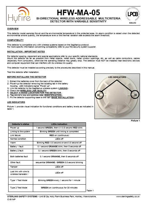
OVERVIEWThis detector model samples the air and the environmental temperature in the protected area. An alarm condition is raised when the detected environmental smoke quantity, the temperature level or the thermal variation rate exceeds the alarm threshold.COMPATIBILITYThis detector is compatible only with wireless systems based on the Sagittarius protocol.For more specific information concerning compatibility refer to your fire security system supplier.INSTALLATION - IMPORTANT NOTESFor detector spacing, placement and special applications refer to your specific national standards.Mount the detector as far as possiblefrom metal objects,metal doors, metal window openings, etc. as well as cable conductors, cables (especially from computers), otherwise the operating distance may greatly drop. The detector must NOT be installed near electronic devices and computer equipment that can interfere with its wireless link quality.This detector must be installed according precisely to the procedures described in this manual.Test this detector after installation.BEFORE INSTALLING THE DETECTOR1) Extract the batteries cover from the back of the detector.2) Power -up the detector removing the isolating tab in the battery housing. LED indicators signal “Power up ”.3) Link the detector to the Sagittarius wireless system (LINKING ). 4) Check the WIRELESS LINK QUALITY .5) SELECT A GOOD LOCATION FOR THE DETECTOR . 6) Tag device ’s loop and address data (IDENTIFICATION ).7) Fix the detector supporting base to the wall (BASE INSTALLATION ).LED INDICATORSPicture 1: provide visual indication for functional conditions and battery levels as indicated in table 1.HFW -MA -05BI -DIRECTIONAL WIRELESS ADDRESSABLE MULTICRITERIADETECTOR WITH VARIABLE SENSITIVITYLED INDICATORS Picture 1928m/02LINKINGrefer to the translator ’s or the Wirelex configuration software ’s literature):1) Move the link switch ’call it BLANK, since it carries no indication). LED indicators signal “system ” (picture 2).Linking is successful when: a) the translator indicates so (check translator ’s literature)ORb) the Wirelex software indicates so (check the Wirelex ’s literature).If linking is unsuccessful:2) Check if evident mistakes were made.3) Perform the LINKING RECOVERY .LINKING RECOVERY1) Take out both batteries from their holders2) Move alternatively the link switch to ON / BLANK five times (picture 2) 3) Move the link switch to ON4) Reinsert both batteries into their holders, oriented as per polarity marks5) Perform the LINKING procedure.DETECTOR SENSITIVITY SETTINGSDuring installation using the Wirelex software it ’s possible to set the smoke sensitivity and the heat class of the detector (see tables 4 and 5). Otherwise if the installation is performed manually through the translator keyboard, default setting will be applied.WIRELESS LINK QUALITYIt is possible to check wireless link quality between the detector and its linked -to translator or expander in this way:1) Move the link switch to the ON position.2) LED indicators will start blinking according to the following table:3) NOTE: Ensure the link switch is returned to the "BLANK" (operational) position on completion of testing.SELECT A GOOD LOCATION FOR THE DETECTORChoose for the detector a placement position that:- compliances with your specific standards- is reached by a strong wireless signal from its linked -to translator or expander module- is not interfered by environmental factors.IDENTIFICATIONFor identification purposes, analogue loop number and device ’address can be recorded on the plastic tag supplied with base (picture 3).base.**********************.ukL20-LMCXX -1400 (vA.2)Picture 3Assessment Device ’s indicationDuring the linking phase, the detector must be positionedclose to the aerial (within a few centimeters) of the translator or expander to which it is being linked. Picture 2 Link switchBASE INSTALLATIONFix the base to the wall with the provided screws (picture 4).DETECTOR PLACEMENT1)Install the batteries cover.2)Position the detector centrally on the baseensuring it is level.3)Rotate clockwise applying gentle pressure.The detector will drop into its keyed location.4)Continue to rotate clockwise a few degreesuntil the detector has fully engaged in thebase.5)When the detector is firmly engaged, checkthe alignment of the raised reference markson the detector and on the base (picture 5).DETECTOR LOCKINGTo lock the detector to the base, screw in the provided security screw; screw entry is locat-ed on the side of the detector’s base (picture 6).TAMPER DETECTIONWhen the detector is detached from the base a tamper message event is sent to the control panel.TESTINGTest this detector after installation.After each test reset the fire security system from the control panel, as per your control panel in-structions.TEST MODESTest modes make the HFW-MA-05 more reactive to aerosol stimulus; two test mode types are provided:Type 1 Test Mode -almost instantaneously alarm agent reactive.Type 2 Test Mode -makes the detector as reactive to smoke as an optical smoke detector, simulating it.TEST 1 - MAGNET TEST1) Hold a suitable magnet in correspondence of the indicated area (picture 7)2) LED indicator will signal “Type 1 Test Mode”3) Apply again the magnet in correspondence of the indicated area (picture 7)4) LED indicator will signal “Alarm”TEST 2 - AEROSOL TESTUse only suitable aerosol testers supplied by approved manufacturers.1) Hold a suitable magnet in correspondence of the indicated area (picture 7)2) LED indicator will signal “Type 1 Test Mode”3) By following its specific instructions, apply the aerosol test device to the detector4) Wait a few seconds5) LED indicator will signal “Alarm”TEST 3 - AEROSOL TESTUse only suitable aerosol testers supplied by approved manufacturers.1) Remotely activate the detector’s green LED from the Wirelex program2) LED indicator will signal “Type 2 Test Mode”3) By following its specific instructions, apply the aerosol test device to the detector4) Wait a few seconds5) LED indicator will signal “Alarm”TEST 4 - HEAT TESTUse only suitable heat test devices from approved manufacturers.1) By following its specific instructions, apply the heat test device to the detector.2) Wait a few seconds.3) LED indicator will signal “Alarm”.Picture 5Dust covers DO NOT providecomplete protection againstcontamination: detectorsshould be removed before construc-tion, major re-decoration or other dustproducing work is started.Dust covers MUST be removed beforethe system can be made operational.Picture 4Picture 6Picture 7MAINTENANCE - CLEANING1) Remove the detector from its base.2) Smoke entry areas and thermistor area: use asoft bristle brush to dislodge any obvious such as insects, spider webs, hairs, etc.3) Smoke entry areas and thermistor area: use a blow any remaining small particles away.4) damp, lint -free cloth to remove any surface film that later attract airborne contaminants.5) Install the detector onto its base again.6) Test the detector. MAINTENANCE - BATTERY REPLACEMENTWhen a low battery condition is indicated, both batteries must be changed altogether.During this procedure the linking switch must NOT be touched at all !1) Detach the detector from its base.2) Extract the batteries cover.3) Extract the batteries.4) Insert the new batteries into their holders, oriented as per polarity marks.5) Reinstall the batteries cover.6) Reinstall the detector onto its base.7) Test the detector.**********************.ukL20-LMCXX -1400 (vA.2)Table 3Table 4Table 5* When a low battery condition is indicated, both batteries must be changed for new cells. Lifespan of batteries indicated is subject to standard environmental conditions, default monitor settings and excellent link quality.** Check latest version of document TDS -LMCXX for further data, obtainable from your supplier.。
certufucate of analysis
certufucate of analysisCertificate of Analysis (COA) is a document provided by a testing laboratory or a manufacturer to ensure the quality and authenticity of a product. It contains detailed information about the product's composition, purity, potency, and other relevant parameters. The COA serves as a proof of quality and safety for consumers and regulatory authorities. In this article, we will discuss the importance of COA and the key information it typically includes.The primary purpose of a Certificate of Analysis is to provide transparency and assurance to consumers regarding the quality and safety of a product. It is especially crucial in industries where the accuracy of product claims can have significant implications on consumers' health and well-being, such as pharmaceuticals, food supplements, and cosmetics.One of the key components of a COA is the product identification section. This section includes essential details like product name, batch or lot number, manufacturing date, and expiration date. These details help consumers and regulatory authorities track and identify specific product batches, ensuring traceability and accountability.Another critical aspect of a COA is the composition analysis. This analysis provides information about the product's ingredients and their respective concentrations. It ensures that the product does not contain any prohibited substances or allergens. For example, in food supplements, the COA may specify the presence and concentration of vitamins, minerals, and other active ingredients. In cosmetics, it may outline the composition of essential oils,preservatives, and other chemicals used in the formulation.Purity and potency testing are often included in a COA. These tests verify that the product is free from impurities, contaminants, or adulterants that may compromise its quality or safety. For pharmaceuticals, purity and potency testing help ensure that the product meets the required standards for efficacy and dosage accuracy. In the case of dietary supplements, it ensures that the product does not contain harmful substances, such as heavy metals or microbial contaminants.The COA may also include details about the testing methods used to analyze the product. This information is crucial for evaluating the validity and reliability of the results. Common analytical techniques include chromatography, spectroscopy, and microbiological testing. By providing information about the testing methods, consumers and regulatory authorities can assess the accuracy and precision of the analysis.Furthermore, a COA may include information about the testing laboratory or manufacturer, such as their accreditation status and certifications. This adds an additional layer of credibility to the document. Accreditation from recognized bodies ensures that the laboratory or manufacturer has undergone rigorous assessments of their competence and compliance with international standards.In conclusion, a Certificate of Analysis plays a vital role in ensuring the quality and safety of products. It provides consumers and regulatory authorities with essential information regarding the product's composition, purity, potency, and testing methods. Bytransparently disclosing this information, the COA enhances trust, accountability, and confidence in the product.。
PAHs欧盟最新标准AfPS-GS-2014-01-PAK-EN

3Leabharlann AfPS GS 2014:01 PAK
Testing and assessment of polycyclic aromatic hydrocarbons (PAHs) in the course of awarding the GS mark
Preliminary observations On Aug. 4th 2014 the Product Safety Commission (AfPS) has assigned the requirements of PAH testing in the course of GS mark certification as specification according to art. 21 Product Safety Act (ProdSG) para. 1 no. 3. The implementation is achieved by means of this PAH document.
2. Basics PAH contamination of materials is primarily due to the use of: - PAH contaminated softening oils in rubber and flexible (soft) plastics - PAH-contaminated carbon black as a black pigment in rubber, plastics and paints. PAH contamination has previously been detected not only in rubber but also in various types of plastic, e.g. ABS and PP, and various paints/coatings, as well as in a variety of natural materials.
大连海事大学航海英语3080

[2201] Which document lists all the lifesaving equipment required for a vessel ?______A. Certificate of InspectionB. American Bureau of Shipping Classification CertificateC. International Convention for the Safety of Life at Sea CertificateD. Certificate of Registry哪一个文件列出船上要求的救生设备?检验证书[2202] Which document will describe lifesaving equipment located aboard your vessel?______A. Muster ListB. Certificate of InspectionC. Forecastle CardD. Clearance Papers哪种文件上有你船上关于救生设备的描述?检查证书。
[2203] Which emergency equipment should you keep near the towing bitts ?______A. A self-contained breathing apparatus (SCBA)B. A boat hook and a spanner wrenchC. A fire ax and / or cutting torchD. A Stokes litter basket你应该在拖带缆桩旁边准备什么紧急设备?消防斧或者切割器。
[2204] Which ending is NOT acceptable in a wire rope that is free to rotate when hoisting?A. Poured socketB. Liverpool eye spliceC. Eye formed with a pressure clamped sleeveD. Eye formed by clips为了让钢丝绳吊起时不至于旋转下面哪种绳端不被采用?利物浦眼接头。
基于DB-YOLO的双基地雷达弱运动目标检测方法
第 22 卷 第 2 期2024 年 2 月太赫兹科学与电子信息学报Journal of Terahertz Science and Electronic Information TechnologyVol.22,No.2Feb.,2024基于DB-YOLO的双基地雷达弱运动目标检测方法陆源,宋杰,熊伟,陈小龙(海军航空大学信息融合研究所,山东烟台264001)摘要:非合作双基地雷达因其特殊的探测方式,致使回波中目标信噪比较低,特别是海上运动目标,在雷达扫描周期的帧与帧之间探测并不稳定,会对后续目标跟踪造成较大困难。
本文首先采用低门限恒虚警率(CFAR)检测器将雷达距离-多普勒维和距离-方位维的检测结果匹配,得到相应掩码图,筛选出潜在的运动目标;然后提出一种融合多维特征信息的双主干YOLO(DB-YOLO),该网络采用双主干结构,同时提取动目标掩码图和其映射下相同尺度P显图的特征,并采用深度可分离卷积模块降低网络的模型参数。
将该模型与Faster RCNN、YOLOv5及其常见变种YOLOv5-ConvNeXt进行对比,实验表明,DB-YOLO有效提高了目标检测性能并保证了推理速度,为非合作双基地雷达的目标跟踪奠定了基础。
关键词:非合作双基地雷达;目标检测;双主干YOLO;特征融合中图分类号:TN914.42 文献标志码:A doi:10.11805/TKYDA2023170Bistatic radar weak moving target detection method based on DB-YOLOLU Yuan,SONG Jie,XIONG Wei,CHEN Xiaolong(Research Institute of Information Fusion,Naval Aviation University,Yantai Shandong 264001,China) AbstractAbstract::Non-cooperative bistatic radar has a low signal-to-noise ratio in the echo due to its special detection method. In particular, the detection between frames in the radar scanning cycle formaritime moving targets is not stable, which will bring great difficulties for subsequent target tracking.The low threshold Constant False Alarm Rate(CFAR) detector is employed to match the detection resultsof radar range-Doppler dimension and range-azimuth dimension to obtain the corresponding mask map,and the potential moving targets are found. Then, a Double Backbone-YOLO(DB-YOLO) that fusesmulti-dimensional feature information is proposed. The network adopts a dual-trunk structure, extractsthe features of the moving target mask map and the same-scale P-display map under its mapping, anduses a deep separable convolution module to reduce the model parameters of the network. Finally, thecomparison experiments with Faster RCNN, YOLOv5 and its common variant YOLOv5-ConvNeXt showthat DB-YOLO effectively improves the target detection performance and ensures the inference speed,which lays a foundation for target tracking of noncooperative bistatic radar.KeywordsKeywords::non-cooperative bistatic radar;target detection;DB-YOLO;feature fusion 随着现代战场的电磁环境日益复杂,传统的有源雷达由于其主动发射电磁波,容易被敌方发现,人们开始研究新体制雷达,即非合作双基地雷达。
exploration technologies and practices 1
15
EXPLORATION RETURNS
• Since 1997, exploration full cycle returns have averaged 17% (based on US$ 70/barrel forward Brent price) • But since 1999 overall trend has been down • And for the period 2004-2007 much of the value gained from higher oil prices has been offset by:
19
ROLE OF TECHNOLOGY
PHASE
DURATION (YEARS)
3–6 1–3 3–7 15 - 30
GEOLOGICAL RISK
VERY HIGH MODERATE/ LOW LOW VERY LOW
INVESTMENT LEVEL
HIGH HIGH VERY HIGH OPERATING COSTS
9
EXPLORATION INVESTMENT
GLOBAL EXPLORATION INVESTMENT SINCE 1997
10
EXPLORATION INVESTMENT
• Increase in oil price has encouraged industry to invest more in exploration • Major companies have been responsible for most of the increase • But all categories of companies have spent more on exploration • Part of the increase in exploration expenditures has been in response to increased costs
技能认证船舶英语考试(习题卷6)

技能认证船舶英语考试(习题卷6)第1部分:单项选择题,共30题,每题只有一个正确答案,多选或少选均不得分。
1.[单选题]Automatic identification systems(AIS)are required to ______.A)provideB)receiveC)exchangeD)all答案:D解析:2.[单选题]A printer would be considered a(n) ______.A)controllerB)peripheralC)inputD)US答案:B解析:3.[单选题]The main objective of the SOLAS Convention is ______.A)toB)toC)toD)to答案:C解析:4.[单选题]Anti-Virus protects your computer from viruses by ___your computer's memory and disk devices.A)deletingB)changingC)replacingD)scanning答案:D解析:5.[单选题]What would the amps be at 240 volts with an 8 ohm resistance?A)32.5B)25C)3D)30答案:D解析:【注】欧姆定律公式I = U/R6.[单选题]A feedback is an input ______.解析:【注】feedback:反馈7.[单选题]A process of comparing the actual performance of a machine with the intended performance, and then adjusting the machine to reduce and eventually eliminate the difference between the actual and intended performance is called ______.A)openB)feedbackC)combiningD)integral答案:B解析:【注】actual performance:实际性能;intended performance:预期性能8.[单选题]The difference between measured and desired values is called _________.A)offsetB)errorC)deviationD)set答案:C解析:【注】deviation:偏差9.[单选题]In the bridge or engine control room ACP of AC C20, the telegraph is ______.A)theB)theC)theD)the答案:A解析:10.[单选题]For revolution speed regulating, a ______ can give stepless speed regulation.A)governorB)frequencyC)speedD)frequency答案:B解析:11.[单选题]Electro-technical officers are working under the leadship of the ______.A)masterB)shipC)engineerD)chief答案:D解析:12.[单选题]______ is not the dry cargo vessel.A)The13.[单选题]In a series circuit, which value will remain unchanged at all places in the circuit?A)VoltageB)CurrentC)ResistanceD)In答案:B解析:14.[单选题]Radar makes it possible and much safer for us to sail ______.A)inB)inC)inD)in答案:A解析:【注】boisterous:凶猛的,粗鲁的15.[单选题]If both the "high level" and "low level" alarms come on for the same address of a centralized control console, the most likely problem is a/an _____.A)sensorB)failedC)lowD)extremely答案:A解析:16.[单选题]A ground can be defined as an electrical connection between the wiring of a motor and its_____.A)shuntB)circuitC)metalD)inter-pole答案:C解析:17.[单选题]In the 7 inch colour graphics display of ACP in AC C20 system, which information can NOT be displayed?A)TheB)TheC)TheD)The答案:C解析:18.[单选题]The operation of paralleling two alternators requires the voltages to be _____ and also in phase.19.[单选题]The controlled object and parameter of the fuel oil viscosity control system are ______.A)theB)theC)theD)the答案:D解析:20.[单选题]Internet Explorer, Firefox, Google Chrome, Safari, and Opera are the major ______.A)webB)uniformC)fileD)Java答案:A解析:21.[单选题]With respect to automatic identification systems(AIS), which information is expected to be broadcast every 1 to 10 seconds?A)RateB)LatitudeC)NavigationalD)All答案:D解析:【注】latitude:纬度;longitude:经度22.[单选题]In the short circuit protection of the automatic power plant, ______. The purpose of this measure is to prevent the 2nd short circuit.A)theB)theC)theD)all答案:C解析:23.[单选题]The closed-loop system differs from the open-loop system by ______.A)theB)theC)theD)the答案:B解析:24.[单选题]The ionization sensor is the commonly used detecting device in capacious space; it detects the ______ of fire.25.[单选题]If the resistance of a circuit is cut in half and the applied voltage is kept constant, the current flow will be _____.A)doubledB)quadrupledC)unchangedD)cut答案:A解析:【注】quadruple:四倍。
塔里木盆地顺托果勒地区北东向走滑断裂带的油气勘探意义
石 ib -b k f W jt A第3#卷第5期OIL (GAS GEOLOGY2017年10月文章编号=0253 -9985(2017)05 -0831 -09doi:10.11743/ogg20170501塔里木盆地顺托果勒地区北东向走滑断裂带的油气勘探意义焦方正(中国石化股份有限公司油田事业部,北京100029)摘要:古隆起碳酸盐岩风化壳领域是多年来塔里木盆地油气勘探发现的重要领域。
近年来,在塔中、塔北古隆起之间的顺托果勒低隆、斜坡区,通过新的地震资料识别出一系列走滑断裂带,且钻井揭示其具有较好的含油气性,相继在顺南、顺托、顺北实现重大油气突破。
顺托果勒地区北东向左行走滑断裂带在构造样式上具有“纵向分层变形、深部主滑移带沿走向分段变形”的特征,上奥陶统及其之上的碎屑岩层系多发育雁列式正断层,其下部对应于发育在碳酸盐岩层系的走滑断层主滑移带。
受斜列侧接部位局部应力场改变的影响,走滑断裂带深部通常表现为拉分负花状、压隆正花状及平移平直状3类样式。
多期活动的系列北东向走滑断裂带形成了规模较大的碳酸盐岩缝洞体系,为后期埋藏溶蚀改造形成规模储层和油气运聚均提供了有利条件,具有明显的“控储、控藏、控富”特征。
在这种奥陶系发育较为齐全的低隆斜坡区呈现出沿断裂带大面积富含油气的勘探形势,具有不同于古隆起暴露剥蚀区风化壳领域的油气成藏模式,使得“塔河之外找塔河”成为可能,已初步落实轻质油资源量12 x 10#=,将成为中石化塔里木探区“十三五”期间增储建产的主战场。
关键词:热液溶蚀改造;断裂控储;走滑断裂带;顺托果勒地区;塔里木盆地中图分类号:TE121.2 文献标识码!ASignificance of oil andgas explorationinNEstrike-slipfault belts inShuntuoguole area of Tarim BasinJiao Fangzheng(Oilfield Business Division,China Petroleum and Chemical Corporation,Beijing 100029,China)Abstract:For years,the carbonate weathering crust of paleo-uplifts has been a major exploration domain in Ta A series of strike-slip fault belts were recognized with updated seismic data in the Shuntuoguole low up tween the Tazliong and Tabei paleo-uplifts in Tarim Basin.Drilling data from the area revealed great oi and later significant oil and gas discoveries in the south (also called Shunnan)and north (also called Shunbei)parts aswell as Shuntuo of the area verified the revelation.The left lateral strike-slip fault belts of north-east trending in the areaare characterized by“layered deformation in vertical direction and segmented deformation along strike of the major slipzone in the d eep*.Echelon normal faults are common in the clastic rocks in the upper Ordovician and layers above it.Thelower Ordovican corresponds t o the major strike-slip zone developed in carbonates.Local stress field variation in echelonand side joint parts had shaped the strike-slip fault belts into three types of structural patterns:pull-apart pattern,compressive uplifting p ositive flower pattern and straight parallel displacement.The strike-slip fault belts withmultiple stages of a ctivities formed massive carbonate fracture-vug systems,which provided favorable conditions for themigration and accumulation of oil and gas after a later burial and dissolution process and showed obvious features of “controlling reservoir formation,hydrocarbon accumulation and enrichment*.The slope zones of low-uplifts with fullydeveloped Ordovician feature in extensive hydrocarbon accumulation along the fault belts,which is different from those in weathering crust of the exposed and denuded paleo-uplifts.The understanding of the new hydrocarbon accumulationpattern made it possible to obtain another T ahe-like discovery.Currently,about 1.2 billion tons of light oil resources havebeen confirmed,making the area a main“battlefield”of achieving the goal of reserve growth and pr收稿日期=2017-03-01!修订日期:2017-07-03。
炼油污泥油含量检测方法探究
炼油与化工REFINING AND CHEMICAL INDUSTRY第34卷炼油污泥油含量检测方法探究田超1,袁康2,马春阳2(1.陕西延长石油(集团)有限责任公司永坪炼油厂,陕西延川717208;2.陕西延长石油(集团)有限责任公司炼化公司,陕西洛川727406)摘要:文中主要探究了炼油污泥油含量直接测量的方法,对比研究了油泥几种不同的前处理方法,得出使用无机化学试剂使污油泥脱水分离,四氯乙烯溶解,红外分光光度法测定油泥中含油量的试验方法。
解决了长期以来通过测定油泥中含水和含泥沙杂质含量,间接计算油泥含油量、测定过程繁杂、结果不准确等问题,验证了1种更加准确、方便的炼油污泥油含量检测的新方法。
关键词:炼油污泥;油含量;脱水;红外分光中图分类号:TE622文献标识码:B文章编号:1671-4962(2023)05-0052-03Exploration of detection methods for oil content of refining sludgeTian Chao1,Yuan Kang2,Ma Chunyang2(1.Yongping Refinery,Shaanxi Yanchang Petroleum(Group)Co.,Ltd.,Yanchuan717208,China;2.Refinery&Chemical Company,Shaanxi Yanchang Petroleum(Group)Co.,Ltd.,Yan'an727406,China)Abstract:This paper mainly explored thedirect determination method of oil content in refining sludge,compared and studied several different sludgepretreatment methods,obtained the trial method of dewatering and separating the sludge with inorganic chemical reagent,dissolving the tetrachloroethylene,and determining the oil content in the sludge by infrared spectrophotometry, solved the problems of complicated process and inaccurate result in the determination of the oil content in the sludge by measuring the content of water and sediment and indirectly calculating the oil content in the sludge,and verifiedthe accuracy and convenience of this new method.Keywords:refinery sludge;oil content;dewatering;infrared spectroscopy石油炼制过程中会产生大量含油污水,在处理过程中一般需要使用到聚丙烯酰胺、聚合氯化铝等不同类型的添加剂,用来吸附和凝聚石油类物质等,形成含油浮渣,以达到油水分离净化污水的目的[1]。
保护海边的措施英语作文初一

保护海边的措施英语作文初一The world's coastlines are some of the most precious and fragile ecosystems on Earth. From the vibrant coral reefs teeming with marine life to the serene sandy beaches that draw millions of visitors each year the seaside is a truly remarkable and irreplaceable natural wonder. However these delicate environments face a multitude of threats from human activity pollution and climate change. It is crucial that we take immediate and decisive action to protect our coastlines for future generations. In this essay I will outline several key measures that can be implemented to safeguard the health and beauty of our beloved seasidesOne of the most pressing issues facing coastal regions is the problem of pollution. Plastic waste plastic bags and microplastics pose a grave danger to marine ecosystems. Sea turtles and other creatures often mistake floating plastic bags for food and ingest them leading to internal blockages and starvation. Microplastics which are tiny pieces of broken down plastic can be ingested by plankton and work their way up the food chain contaminating the seafood that humans consume. To combat this scourge of plasticpollution governments must enact bans on single-use plastics such as plastic bags straws and bottles. Incentives should be provided for businesses to use biodegradable or reusable alternatives. Beach cleanups organized by local communities can also play a vital role in removing existing plastic waste from shorelines. Education campaigns to raise awareness about the plastic pollution crisis and encourage people to reduce their plastic usage are another essential component of the solution.Coastal regions are also under threat from oil spills which can devastate marine life and ecosystems. When oil is spilled into the ocean it can form a thick slick on the surface preventing sunlight from penetrating the water and disrupting photosynthesis in plankton. Birds and other animals that rely on the ocean can become coated in oil leading to hypothermia and drowning. To mitigate the risk of oil spills stricter regulations and safety protocols must be implemented for offshore drilling operations. Contingency plans and rapid response mechanisms need to be in place to quickly contain and clean up any spills that do occur. Investing in advanced oil spill detection and cleanup technologies can also greatly improve the ability to minimize the environmental damage caused by these disasters.Habitat destruction is another major threat facing coastal regions. The construction of seawalls breakwaters and other coastalinfrastructure can disrupt natural sand and sediment flows leading to beach erosion. Deforestation of mangrove forests and other coastal vegetation removes crucial habitats and natural barriers that protect against storms and flooding. To preserve the integrity of coastal ecosystems development in these areas must be carefully planned and regulated. Environmental impact assessments should be mandatory for any proposed construction projects. Protecting and restoring natural habitats like mangrove forests and coral reefs should be a top priority. Sustainable ecotourism models that allow people to enjoy and appreciate these environments without causing harm can also play an important role.Climate change poses an existential threat to coastal regions around the world. Rising sea levels driven by melting glaciers and ice caps are causing more frequent and severe flooding events. Increased ocean temperatures are bleaching and killing off coral reefs. Stronger hurricanes and typhoons fueled by warmer ocean waters are battering shorelines with ever-greater intensity. To build resilience against these climate change impacts coastal communities must invest in robust flood defense systems like seawalls and storm surge barriers. Protecting and restoring natural coastal habitats like mangroves and wetlands can also help to mitigate the effects of flooding and erosion. Transitioning to renewable energy sources and reducing greenhouse gas emissions are crucial for slowing the pace of global warming and sea level rise in the long term.In conclusion the world's seasides are precious natural assets that provide immense ecological economic and recreational value. However they face a multitude of threats that require a comprehensive and multi-faceted response. Tackling plastic pollution oil spills habitat destruction and climate change impacts through a combination of legislation regulation and community-driven initiatives will be essential to safeguarding the future of our beloved coastlines. By taking bold and immediate action we can preserve these irreplaceable environments for generations to come.。
oil extraction看法作文英语

oil extraction看法作文英语My Perspective on Oil ExtractionOil extraction has long been a pivotal activity in the global economy, shaping the development of nations and the lives of individuals. However, it is also a topic that evokes complex emotions and diverse opinions.On one hand, oil extraction is essential for the functioning of modern society. It fuels our cars, heats our homes, and powers our industries. Without oil, the world we know today would be drastically different. Moreover, oil extraction provides jobs and economic opportunities in many regions, contributing significantly to local economies.However, the extraction and use of oil also have significant environmental and social costs. Oil spills and leaks can contaminate vast areas of land and water, while the burning of oil releases greenhouse gases that contribute to climate change. Furthermore, oil extraction often takes place in sensitive ecosystems, displacing wildlife and destroying habitats.Additionally, oil extraction can have serious socialimplications. Disputes over oil resources have led to conflicts and wars, causing immense suffering and displacement. In some cases, oil extraction has also been linked to human rights abuses and corruption.In my view, oil extraction is a necessary evil in today's world. While we must continue to rely on oil to meet our energy needs, we must also strive to reduce its environmental and social impacts. This means investing in renewable energy sources, improving oil extraction technologies, and ensuring that oil extraction activities are conducted in a responsible and sustainable manner. Only by balancing the economic benefits of oil extraction with its environmental and social costs can we ensure a sustainable future for our planet.。
润滑油荧光光谱标准物质
润滑油荧光光谱标准物质英文回答:Fluorescence spectroscopy is a widely used technique in the analysis of lubricating oils. It provides valuable information about the composition and quality of the oil. In order to ensure accurate and reliable measurements, itis important to have standardized reference materials for calibration and validation purposes. These reference materials are known as fluorescence spectral standard substances or standard solutions.The fluorescence spectral standard substances are carefully prepared to have well-defined and reproducible fluorescence properties. They are typically composed of known concentrations of specific fluorescent compounds that are commonly found in lubricating oils. These compounds are chosen based on their characteristic fluorescence spectra and their relevance to the analysis of lubricating oils.For example, one common fluorescent compound used in lubricating oil analysis is polycyclic aromatic hydrocarbons (PAHs). PAHs are formed during the combustionof fossil fuels and can be present in lubricating oils as contaminants. By measuring the fluorescence intensity and emission spectra of PAHs, we can determine theconcentration of these contaminants in the oil.Another example is the use of fluorescent dyes as standard substances. These dyes are specifically designedto exhibit strong fluorescence properties and are added to lubricating oils to enhance their visibility under UV light. By comparing the fluorescence spectra of the dye in the oil sample to the fluorescence spectra of the standard dye solution, we can assess the quality and performance of the oil.In addition to PAHs and fluorescent dyes, other fluorescent compounds such as antioxidants, detergents, and wear metals can also be used as standard substances. These compounds play important roles in the performance and longevity of lubricating oils. By measuring theirfluorescence properties, we can gain insights into the condition and effectiveness of the oil.The availability of fluorescence spectral standard substances is crucial for the calibration and validation of fluorescence spectroscopy instruments used in lubricating oil analysis. These standards ensure the accuracy and reliability of the measurements, allowing for consistent and meaningful interpretation of the fluorescence data.中文回答:荧光光谱是润滑油分析中常用的技术手段之一。
ASTM D6594-01
Designation:D 6594–01An American National StandardStandard Test Method forEvaluation of Corrosiveness of Diesel Engine Oil at 135°C 1This standard is issued under the fixed designation D 6594;the number immediately following the designation indicates the year of original adoption or,in the case of revision,the year of last revision.A number in parentheses indicates the year of last reapproval.A superscript epsilon (e )indicates an editorial change since the last revision or reapproval.INTRODUCTIONAny properly equipped laboratory,without outside assistance,can use the procedure described in this test method.However,the ASTM Test Monitoring Center (TMC)2provides reference oils and an assessment of the test results obtained on those oils by the laboratory (see Annex A1).By these means,the laboratory will know whether their use of the test method gives results statistically similar to those obtained by other laboratories.Furthermore,various agencies require that a laboratory utilize the TMC services in seeking qualification of oils against specifications.For example,the U.S.Army imposes such a requirement in connection with several Army engine lubricating oil specifications.Accordingly,this test method is written for use by laboratories that utilize the TMC boratories that choose not to use those services may simply ignore those portions of the test method that refer to the TMC.This test method may be modified by means of information letters issued by the TMC.In addition,the TMC may issue supplementary memoranda related to the method (see Annex A1).For other information,refer to the research report of this test method 3.1.Scope1.1This test method is used to test diesel engine lubricants to determine their tendency to corrode various metals,specifi-cally alloys of lead and copper commonly used in cam followers and bearings.1.2The values stated in SI units are to be regarded as the standard.1.3This standard does not purport to address all of the safety concerns,if any,associated with its use.It is the responsibility of the user of this standard to establish appro-priate safety and health practices and determine the applica-bility of regulatory limitations prior to use.2.Referenced Documents 2.1ASTM Standards:D 130Test Method for Detection of Copper Corrosion fromPetroleum Products by the Copper Strip Tarnish Test 4D 5185Test Method for Determination of Additive Ele-ments,Wear Metals,and Contaminants in Used Lubricat-ing Oils and Determination of Selected Elements in Base Oils by Inductively Coupled Plasma Atomic Emission Spectrometry (ICP-AES)5D 5844Test Method for Evaluation of Automotive Engine Oils for Inhibition of Rusting (Sequence IID)6D 6557Test Method forEvaluation of the Rust Preventive Characteristics of Automotive Engine Oils 7E 691Practice for Conducting an Inter-Laboratory Study to Determine the Precision of a Test Method 83.Terminology 3.1Definitions:3.1.1corrosion ,n —the chemical or electrochemical reac-tion between a material,usually a metal surface,and its environment that can produce a deterioration of the material and its properties.D 58443.1.2developer ,n —of an ASTM test method ,the assigned ASTM group,working under the supervision of its governing1This test method is under the jurisdiction of ASTM Committee D02on Petroleum Products and Lubricants and is the direct responsibility of Subcommittee D02.B0on Automotive Lubricants.Current edition approved Nov.10,2001.Published January 2002.Originally published as D st previous edition D 6594-00.2The ASTM Test Monitoring Center will update changes in this test method by means of Information Letters.This edition incorporates revisions contained in all Information Letters through rmation Letters may be obtained from the ASTM Test Monitoring Center,6555Penn Ave.,Pittsburgh,PA 15206-4489,Attention:Administrator.3Available from ASTM International Headquarters.Request the High Tempera-ture Corrosion Bench Test Research Report,RR:D02-1443.4Annual Book of ASTM Standards ,V ol 05.01.5Annual Book of ASTM Standards ,V ol 05.02.6Annual Book of ASTM Standards ,V ol 05.03.7Annual Book of ASTM Standards ,V ol 05.04.8Annual Book of ASTM Standards ,V ol 14.02.1Copyright ©ASTM International,100Barr Harbor Drive,PO Box C700,West Conshohocken,PA 19428-2959,United States.NOTICE:This standard has either been superseded and replaced by a new version or withdrawn.Contact ASTM International ()for the latest informationsubcommittee and main committee,that formats the test method in accordance with the Form and Style for ASTM Standards,and continually refines the test method.3.1.3developer,n—of a test procedure,an individual or organization that selects the test apparatus and operating conditions.3.1.4non-reference oil,n—any oil other than a reference oil;such as a research formulation,commercial oil,or candi-date oil.D5844 3.1.5reference oil,n—an oil of known performance char-acteristics,used as a basis for comparison.D5844 3.1.5.1Discussion—Reference oils are used to calibrate testing facilities,to compare the performance of other oils,or to evaluate other materials(such as seals)that interact with oils.3.1.6specimen,n—a piece or portion of a sample used to make a test.3.1.7sponsor,n—of an ASTM test method,an organization that is responsible for ensuring supply of the apparatus used in the test procedure portion of the test method.3.1.7.1Discussion—In some instances,such as a test method for chemical analysis,an ASTM working group can be the sponsor of a test method.In other instances,a company with a self-interest may or may not be the developer of the test procedure used within the test method,but is the sponsor of the test method.3.1.8test oil,n—any oil subjected to evaluation in an established procedure.D65574.Summary of Test Method4.1Four metal specimens of copper,lead,tin,and phosphor bronze are immersed in a measured amount of engine oil.The oil,at an elevated temperature,is blown with air for a period of time.When the test is completed,the copper specimen and the stressed oil are examined to detect corrosion and corrosion products,respectively.4.2A reference oil is tested with each group of tests to verify test acceptability.5.Significance and Use5.1This test method is intended to simulate the corrosion process of non-ferrous metals in diesel lubricants.The corro-sion process under investigation is that believed to be induced primarily by inappropriate lubricant chemistry rather than lubricant degradation or contamination.This test method has been found to correlate with an extensivefleet database containing corrosion-induced cam and bearing failures.36.Apparatus6.1The main apparatus consists of the following items of standard wall borosilicate glassware as shown in Figs.1-6.6.1.1Main Sample Tube,Fig.1.6.1.2Sample Tube Head,Fig.2.6.1.3Air Tube,Fig.3.6.1.4Thermocouple Tube,Fig.4.6.1.5Condenser,Allihn Type,Fig.5.6.1.6Assembled Apparatus,Fig.6.6.2Additional glassware items and assembly accessories needed are:6.2.1Hanger(for metal specimens),of stainless steel,hav-ing the dimensions listed in Fig.7.6.2.2Adapter,polytetrafluoroethylene for10/18joint for sealing of the air tube to the sample tube head.6.3Other items and equipment are:6.3.1Heating bath,with constant temperature control within 60.5°C(61°F)of test temperature with an immersion depthofFIG.1SampleTubeFIG.2Sample TubeHead250620mm.Oil baths are recommended.(Warning —There are exposed hot surfaces on apparatus.Avoid skin contact by use of protective equipment.)6.3.2Ventilation ,to adequately remove fumes during heat-ing.6.3.3Dry Air Supply ,with a dew point of −68°C.6.3.3.1When air needs to be conditioned an air drier is required.The method used is optional provided the air char-acteristics of 6.3.3are attained.For drying,a satisfactorymethod is the use of a glass column containing 8-mesh anhydrous calcium sulfate with a column diameter such that velocity of air does not exceed 1.2m/min.6.3.4Flowmeter ,capable of measuring 1061L/h.6.3.5Balance ,with a capacity of 2500g and sensitivity of 0.1g.6.3.6Syringe ,capable of accurately measuring out 100mL of liquid.6.3.7Oven ,optional,to dry glassware at elevated tempera-ture.FIG.3AirTubeFIG.4ThermocoupleTubeFIG.5Condenser,AllihnTypeFIG.6AssembledApparatus6.3.8Forceps ,stainless steel;or gloves (powder free).6.3.9Thermocouple ,or e sheathed thermo-couple when used directly in contact with e unsheathed thermocouple when thermocouple well is used;fill thermo-couple well with a heat transfer medium.6.3.10Sanding Block and Holder ,for specimen preparation.7.Reagents and Materials7.1Purity of Reagents —Use reagent grade chemicals in all tests.Unless otherwise indicated,it is intended that all reagents conform to the specifications maintained by the Committee on Analytical Reagents of the American Chemical Society 9.7.2Metal Specimens 10,117.2.1Specimens are 0.081cm thick by 2.5cm square,except that lead specimen that is 0.178cm thick.One specimen from each of the following metal types,each with two drilled holes,is required:7.2.1.1Copper (R401-A),7.2.1.2Lead (R401-lead),7.2.1.3Tin (R401-tin),and7.2.1.4Phosphor Bronze (R401-PBz).7.3Abrasive Paper 12,240-grit aluminum oxide and 400-grit silicon carbide.Do not use iron-containing abrasives such as natural emery.7.4Cotton ,100%.7.5Acetone (ACS),sulfur free.(Warning—Flammable.Health hazard.)7.6Glassware Cleaning Solution ,NOCHROMIX 13,11.(Warning—Causes severe burns.)7.7Tetrahydrofuran (THF).(Warning—Toxic and flam-mable.Health hazard.)7.8Degreasing Solvent ,(THF recommended).7.9Naphtha ,Aromatic.(Warning—Flammable.Health hazard.)7.10Reference Oil 2.8.Preparation of Apparatus 8.1Cleaning of Glassware :8.1.1Rinse all glassware items and the air tube adapter with degreasing solvent to remove residual oil,and air-dry.8.1.2Wash all glassware items and the air tube adapter with detergent.Rinse with tap water,distilled water,and dry.8.1.3Store all items in a dust-free cabinet until needed for test.If stored longer than one week,rinse again with distilled water before use,and dry.8.1.4The following more thorough glassware cleaning procedure can be used,if it is required for a given situation:8.1.4.1Fill and immerse all glassware items with glassware cleaning solution (see 7.6)and soak for 3to 16h.(Warning—Corrosive,causes severe burns.)9Reagent Chemicals,American Chemical Society Specifications ,American Chemical Society,Washington,DC.For suggestions on the testing of reagents not listed by the American Chemical Society,see Analar Standards for Laboratory Chemicals ,BDH Ltd.,Poole,Dorset,U.K.,and the United States Pharmacopeia and National Formulary,U.S.Pharmacopeial Convention,Inc.(USPC).10Obtain metal specimens from Test Engineering,Inc.(TEI),12718Cimarron Path,San Antonio,TX 78249-3423.11The sole source of supply of the apparatus known to the committee at this time is noted in the adjoining footnote.If you are aware of alternative suppliers,please provide this information to ASTM International Headquarters.Your comments will receive careful consideration at a meeting of the responsible technical committee,which you may attend.12Suitable abrasive paper meeting these specifications is included with the metal specimens when the specimens are ordered.13Obtain NOCHROMIX from Godax Laboratories,Inc.,720-B Erie Avenue,Takoma Park,MD20912.N OTE 1—All dimensions in mm.FIG.7SpecimenHanger8.1.4.2Remove glassware from cleaning solution;rinse several times with tap water,followed by distilled water,and oven-dry.8.1.4.3This more thorough glass cleaning procedure is necessary in a referee situation,unless an alternative glassware cleaning solution is available which is satisfactory to all parties involved.8.2Assembled Apparatus,shown in Fig.6.8.3Preparation of Metal Specimens:8.3.1In all succeeding steps,handle the specimens only with stainless steel forceps or powder-free gloves until thefinal weighing.If large defects or particles are present on the metal specimens,remove themfirst using coarse sandpaper,followed by polishing with the240and400-grit abrasive papers,as described in8.3.2.8.3.2Using a sanding block with a specimen holder,remove all surface blemishes from both sides and all four edges of each specimen with240-grit abrasive paper.Remove any burrs from the drilled holes with a1⁄16in.drill bit.Finish polishing with 400-grit paper wetted by acetone to remove marks from previous polishing.8.3.2.1A good technique is to rub the specimen with longitudinal strokes in direction perpendicular to that used with 240-grit e a different sheet of paper for each metal type.8.3.2.2Make sure that the specimen edges are polished in the same manner as the surfaces.Carry out this procedure using normal room lighting and without magnification of the specimen surface.Do not scribe or otherwise mark the sur-faces.8.3.3Store the polished metal specimens in tetrahydrofuran.8.3.4Just prior to a test start,remove each specimen from the tetrahydrofuran,and clean all metal dust from the specimen using100%cotton.Rub with a light-to-medium touch to remove particles but do not polish the specimen further.8.3.5Wash specimens in tetrahydrofuran and allow them to dry in a desiccator.9.Procedure9.1Place the specimen hanger onto the air tube and hang test specimens on their respective hooks.9.1.1Arrange the specimens on the hanger in the sequence: lead,copper,tin,and phosphor bronze.9.2Insert the air tube with the attached specimens into the sample tube so that the air tube rests on the bottom of the sample tube.9.3Place the sample tube top on the sample tube.9.4Weigh the air tube,sample tube,and contents together within0.1g.9.5Add10061mL of test oil volumetrically to the sample tube by syringe.Reweigh the air tube,sample tube,and contents together to within0.1g,and determine the weight of the oil added.9.6Assemble the sample tube and condenser and mount the assembly so that3065cm of the sample tube is submerged in the bath with the test oil temperature set at13560.5°C.9.7Start theflow of the cooling water through the con-denser jacket.9.8To begin testing,connect the source of clean,dry air(5 60.5L/h)to the air tube and allow the air toflow for168h. House air with pre-drying or bottle reagent grade air should be e a calibratedflow meter in setting airflow rates. 9.9End of Test—After168h at135°C,shut off the airflow and disassemble.9.9.1Remove air supply and disconnect condenser.9.9.2Remove sample tube from the bath,allow it to cool at least for15min,and wipe off the outside of the tube with a cloth dampened with naphtha.9.9.3Make the following measurements:Re-weigh the air tube,sample tube,and contents to within0.1g,determine weight of the oil sample remaining,and compute the percent-age of weight loss resulting from evaporation of oil(see 10.5.1).If the evaporation loss is greater than8%leakage is present.Correct the leak,and repeat the determination,using a fresh oil sample and new specimens.10.Test Results10.1Remove the air tube with the attached specimens from the sample tube.Do not touch the specimens with hands. Retain the sample tube and test oil for further examination.10.2Using forceps or gloves,wash the copper specimen in tetrahydrofuran,and discard the other specimens.10.3Rate the copper specimen for tarnish according to the Strip Examination,Interpretation,and Report sections of Test Method D130.10.4Immediately after calibration of the ICP-AES instru-ment(as specified in Test Method D5185),use Test Method D5185to determine the concentration of copper,lead,and tin in both the new and used oil.10.5Calculations:10.5.1Evaporation Loss:L5@~W12W2!/W3#3100(1) where:L=percent evaporation loss,W1=initial weight of air tube,sample tube and contents, including test oil,W2=final weight of air tube,sample tube and contents, including test oil,andW3=initial weight of test oil.10.5.2Change in metal concentration in the used test oil:D C5C22C1(2) where:D C=change in metal concentration before and after test, C1=measurement of metal concentration in new test oil (as determined in10.4),andC2=measurement of metal concentration in used test oil (as determined in10.4).11.Reference Oil Testing11.1Test a TMC-coded reference oil along with each batch of non-reference oil tests.Run the reference oil simultaneously with,and in the same bath as,the non-reference oils.N OTE1—Annex A1discusses the involvement of the ASTM TMC with respect to the reference test-monitoringprogram.11.1.1Prior to requiring a reference oil test,procure a supply of reference oils directly from the TMC.These oils have been formulated or selected to represent specific chemistry types,or performance levels,or both.Each reference oil sample is identified using a unique set of identification codes on the container labels.The coded reference samples provide for a blind reference-testing program to protect against the possibility of bias in the results.11.1.1.1The testing laboratory tacitly agrees to use the TMC reference oils exclusively in accordance with the TMC’s published Policies for Use and Analysis of ASTM Reference Oils,and to run and report the reference oil test according to TMC guidelines.N OTE2—Policies for the Use and Analysis of ASTM Reference Oils is available from the TMC.11.1.2Request a reference oil assignment from the TMC for this test method.The TMC will determine the specific refer-ence oil to be tested by the laboratory.Assignments will be made by the unique identifying codes on the reference oil container labels.Provide the TMC with the bath identification number for the test.11.1.3Run the TMC reference oil test according to the test method and in the same manner as the non-reference oil test(s).11.1.4Reporting of Reference Oil Test Results—Report the results of all reference oil tests to the TMC according to the following directives:11.1.4.1Use the data reporting formats detailed in Annex A2(see Figs.A2.1-A2.4)for reporting all TMC reference oil test data to the TMC.Report only the reference oil results to the TMC.Do not include any non-reference test plete all of the required blankfields on the forms.11.1.4.2Transmit reference test data to the TMC by elec-tronic means or by telephone facsimile immediately upon completion of the test analysis.Include all of the reporting forms in the transmission.N OTE3—Specific protocols for the electronic transmission of test data to the TMC are available from the TMC.11.1.5Evaluation of Reference Test Oil Results—Upon receipt of the transmitted TMC reference oil test results,the TMC will review the test for operational adherence to the published test method.If the test is found to be operationally valid,the reference oil results will be evaluated using accep-tance criteria established by the governing surveillance panel. The reference oil acceptance criteria are subject to change at the discretion of the surveillance panel.11.1.5.1If the transmitted test is found to be both opera-tionally valid and statistically acceptable,the testing laboratory will be notified of the acceptable status of the reference test. The uncoded TMC reference oil identification will also be disclosed to the testing laboratory.11.1.5.2In the event that a TMC reference oil test is found to be unacceptable,an explanation of the problem relating to the failure will be provided to the testing laboratory.If there is an obvious operational reason for the failed test,the problem shall be corrected before requesting another TMC reference oil assignment.If the reason for the failure is not obvious,all test-related equipment shall be re-checked for compliance to the test method and good laboratory practice.Following this re-check the TMC will assign another TMC reference oil for testing.11.1.6Status of Non-reference Oil Tests Relative to TMC Reference Oil Tests—The batch of non-reference tests is considered valid only if the results of the TMC reference oil test meet the predetermined acceptance specifications for the particular reference oil tested.12.Report12.1Report(see Annex A2for Report Format)the tarnish rating of the copper specimen(as determined in10.3)based on the highest rating(most corrosion)if the rating is different for either side.12.2Report the concentrations of copper,lead,and tin in the new oil(C1in10.5.2)and stressed oil(C2in10.5.2),and the respective changes in metal concentrations(D C in10.5.2).13.Precision and Bias13.1Precision—The precision of the test method was determined by performing round robin tests in seven laborato-ries,in accordance with guidelines in Practice E691.13.1.1Intermediate Precision(I.P.),(formerly called repeat-ability)is defined as the difference between two results obtained by the same operator in the same laboratory,using the same test method on the same oil.Based on round robin tests, Intermediate Precision,in the long run,in the normal and correct conduct of the test method,would exceed the followingI.P.values in only one case in twenty.13.1.2Reproducibility(R),is defined as the difference between two single and independent results obtained by different operators working in different laboratories,using the same test method on the same oil.Based on round robin tests, Reproducibility,in the long run,in the normal and correct conduct of the test method,would exceed the following R values in only one case in twenty.13.1.3D Copper,ppm(with natural log transformation):S I.P.50.272I.P.50.754(3)S R50.400R51.10913.1.4D Lead,ppm.S I.P.56.14I.P.543.02(4) 13.1.5D Tin,content precision to be determined when an appropriate reference oil is located.13.2Bias is unknown at this time,but will be determined as more data are collected.14.Keywords14.1corrosion;diesel engine;lubricantANNEXES(Mandatory Information)A1.THE ROLE OF THE ASTM TEST MONITORING CENTER AND THE CALIBRATION PROGRAMA1.1Nature and Functions of the ASTM Test Monitoring Center(TMC):A1.1.1The TMC2is a non-profit organization located in Pittsburgh,Pennsylvania(USA).The TMC is staffed to admin-ister technical studies,conduct laboratory visits,perform statistical analyses of reference oil test data,blend,store and ship reference oils,and provide associated administrative functions to maintain the referencing calibration program for various lubricant tests as directed by Subcommittee D02.B and the Test Monitoring Board.The TMC coordinates its activities with the test sponsors,the test developers,the surveillance panels,and the testing laboratories through a consensus pro-cess.A1.2Rules of Operation of the TMC:A1.2.1The TMC operates in accordance with the ASTM Charter,the ASTM Bylaws,the Regulations Governing ASTM Technical Committees,the Bylaws Governing ASTM Commit-tee D02,and the Rules and Regulations Governing the ASTM Test Monitoring System.A1.3Management of the TMC:A1.3.1The management of the Test Monitoring System is vested in the Test Monitoring Board(TMB)elected by Sub-committee D02.B.The TMB selects the TMC Administrator who is responsible for directing the activities of the TMC staff. A1.4Operating Income of the TMC:A1.4.1The TMC’s Operating income is obtained from fees levied on the reference oils supplied,and on the calibration tests conducted.Fee schedules are established and reviewed by Subcommittee D02.B.A1.5Conducting a Reference Oil Test:A1.5.1For those laboratories choosing to utilize the ser-vices of the TMC in maintaining the calibration of test methods and apparatus,calibration testing is conducted at regular intervals as determined by the Diesel Lubricants Surveillance Panel.These tests are conducted using coded reference oils supplied by the TMC as outlined in11.1of this test method.It is the laboratories’responsibility to maintain the calibration in accordance with the test method.It is also the laboratories’responsibility to keep an on-site reference oil inventory at or above the minimum level specified by the TMC test represen-tative.A1.6New laboratories:A1.6.1Laboratories wishing to participate in the ASTM Test Monitoring System will be requested to conduct reference oil tests to ensure that the laboratory is using the proper testing rmation concerning fees,laboratory inspec-tions,reagents,testing practices,appropriate committee mem-bership,and rater training can be obtained by contacting the TMC Administrator.2A1.7Introducing New Reference Oils:A1.7.1The calibrating reference oils produce various cor-rosion characteristics.When new reference oils are selected, member laboratories will be requested to run their share of the tests needed to enable the TMC to recommend proper industry performance and precision targets and performance acceptance limits.These donated tests will be run as required by the ASTM D02.B02Corrosiveness of Diesel Lubricants Surveillance Panel to establish these targets and acceptance limits for new oils.A1.8TMC Information Letters:A1.8.1Occasionally it may become necessary to change the test method,and notify the test laboratories of the change,prior to consideration of the change by either Subcommittee D02.B on Automotive Lubricants,or Committee D02on Petroleum Products and Lubricants.In such a case,the TMC will issue an Information Letter.Subsequently,prior to each semiannual Committee D02meeting,the accumulated Information Letters are balloted by Subcommittee D02.B.Following this action, the approved Information Letters are used to revise the affected standards,and these are balloted in the main committee,and finally,the Society.By this means,the Society due process procedures are applied to these Information Letters.A1.8.2The review of an Information Letter prior to its original issue will differ according to its nature.In the case of an Information Letter concerning a part number change,which does not affect test results,the TMC is authorized to issue such a letter.Long-term studies by the Surveillance Panel to improve test procedures through improved operation and hardware control may result in a recommendation to issue an Information Letter.If obvious procedural items affecting test results need immediate attention,the test sponsor and the TMC will issue an Information Letter and present the background and data to the Surveillance Panel for approval prior to the semiannual Subcommittee D02.B meeting.A1.8.3The ASTM Committee on Technical Committee Operations(COTCO)in1984gave authority for the issuance of Information Letters,as follows:“COTCO recognizes that D02has a unique and complex situation.The use of Informa-tion Letters is approved providing each letter contains a disclaimer to the effect that such has not obtained ASTM consensus.These Information Letters should be moved to such consensus as rapidly as possible.”A1.9TMC Memoranda:A1.9.1In addition to the Information Letters discussed under A1.8,supplementary memoranda may be issued bytheTMC.These memoranda are developed by the TMC,often under the guidance of the surveillance panel,and distributed to the Corrosiveness of Diesel Lubricants Surveillance Panel,and to participating laboratories.The memoranda convey such information as approval for test parts or materials,clarification of the test procedure,notes and suggestions of the collection and analysis of special data that the TMC may request,or for any other pertinent matters having no direct affect on test performance,results,precision and bias.A2.REPORT FORMAT AND DATA DICTIONARYA2.1Use the standardized report form package detailed in Annex A2,to report all corrosion evaluation test results for all reference and non-reference oils.A2.2Test Report Forms with Data Dictionary Variable Mnemonics—The following report forms containfield names for all reported e these variable designations in electronic data transmission as defined by the Data Communi-cations Committee;see Figs.A2.1-A2.3.A2.3Test Report Variable Data Dictionary—The following is a complete Data Dictionary of thefield names used in A2.1-A2.3;also see Fig.A2.4.。
日照美食菜单英语版

日照美食菜单英语版1黑椒西芹百合炒东星粤菜的做法,却用了香辣的黑胡椒来提味,每一口都让人惊喜。
stir frying coral trout with black pepper, celery and lilythough cooked in style of cantonese cuisine, it uses spicy and hot black pepperto render more palatable, amazing you at every sup.2特级肋眼皇:(荐)牛扒老饕们的心头好。
中心部位一块明显的油花,非得要烤到七、八分熟,把油脂烧透,散发出牛油香来才最美味。
grilled prime rib steak: (recommended)it is the favorite cate for epicures of grilled fillet steak. a piece ofvisible oil slick in the center, it has to be heavily grilled to seven or eightmedium to burn over the grease and throw off beef suet fragrance, showing offits best taste.3桂花绿豆糕:平日里普普通通的绿豆糕,竟也有如此惊艳的造型。
层层叠叠的心意,清甜在细碎的桂花香末之中。
sweet-scented osmanthus -green bean cake:so rare that an ordinary green bean cake may be sculpted surprisinglypealike! layers and layers of regards are withheld in light-scented bits ofthis osmanthus.4青苹果银鳕鱼:(荐)青苹果,性凉、味甘;银鳕鱼,味咸,性平温。
油品检测新闻稿范文
油品检测新闻稿范文英文回答:Oil Product Testing Press Release.I am pleased to announce the latest advancements in oil product testing. Our company has developed a cutting-edge technology that revolutionizes the way we detect impurities and ensure the quality of oil products.Traditionally, oil product testing has relied on manual inspection and laboratory analysis. However, these methods are time-consuming, expensive, and often yield inconsistent results. Our new technology, called the Automated Oil Quality Analyzer (AOQA), addresses these challenges and provides a more efficient and accurate solution.The AOQA utilizes state-of-the-art sensors and algorithms to detect impurities in oil products. It can analyze multiple parameters, including viscosity, density,and flash point, in a matter of seconds. The results are then compared to industry standards to determine thequality of the oil product. This automated process eliminates human error and ensures consistent and reliable testing results.In addition to its speed and accuracy, the AOQA is also user-friendly. It features a simple interface that allows operators to easily input the sample and obtain the test results. The device is portable and can be used in various settings, such as oil refineries, transportation hubs, and even remote locations.The benefits of the AOQA are numerous. Firstly, it significantly reduces the time and cost associated with oil product testing. With faster results and less reliance on laboratory analysis, companies can streamline their operations and make informed decisions more quickly. Secondly, the AOQA enhances product quality control. By detecting impurities at an early stage, companies can prevent costly recalls and ensure customer satisfaction. Lastly, the AOQA promotes sustainability by reducing waste.With more accurate testing, companies can avoid unnecessary disposal of oil products that do not meet quality standards.To demonstrate the effectiveness of the AOQA, let's consider a hypothetical scenario. Company A is a major oil producer that supplies fuel to various industries. Theyhave been using traditional testing methods, which aretime-consuming and yield inconsistent results. As a result, they have experienced quality issues and customer complaints. Company A decides to implement the AOQA fortheir testing processes. The device quickly detects impurities in their oil products and allows them to take corrective actions before the products are distributed. Asa result, Company A improves their product quality, reduces customer complaints, and saves time and costs associatedwith manual testing.中文回答:油品检测新闻稿。
美国签证敏感专业

The State Department maintains a Technical Alert List, also known as the sensitive major list, to guide their evaluation of visa submission. Sorted by rate.CRITICAL FIELDS LISTA. CONVENTIONAL MUNITIONS: Technologies associated with:-- Warheads and other large caliber projectiles-- Reactive armor and warhead defeat systems-- Fusing and arming systems.-- Electronic countermeasures and systems-- New or novel explosives and formulations-- Automated explosive detection methods and equipmentB. NUCLEAR TECHNOLOGY: Technologies associated with production and use of nuclear material for both peaceful and military applications. Included are technologies for:-- Enrichment of fissile material-- Reprocessing irradiated nuclear fuel to recover produced plutonium-- Production of heavy water for moderator material-- Plutonium and tritium handlingAlso, certain associated technologies related to nuclear physics and/or nuclear engineering. Includes materials, equipment or technology associated with:-- Power reactors, breeder and production reactors-- Fissile or special nuclear materials-- Uranium enrichment, including gaseous diffusion, centrifuge, aerodynamic, chemical, Electromagnetic Isotopic Separation (EMIS), Laser Isotope Separation (LIS)-- Spent fuel reprocessing, plutonium, mixed oxide nuclear research, Inertial Confinement Fusion (ICF)-- Magnetic confinement fusion-- Laser fusion, high power lasers, plasma,-- Nuclear fuel fabrication including Mixed Oxide (uranium-plutonium) fuels (MOX)-- Heavy water production-- Tritium production and use-- Hardening technologyC. ROCKET SYSTEMS (including ballistic missile systems, space launch vehicles and sounding rockets) and Unmanned Air Vehicles (UAV) (including cruise missiles, target drones, and reconnaissance drones): Technologies associated with rocket systems and UAV systems. The technology needed to develop a satellite launch vehicle is virtually identical to that needed to build a ballistic missile.D. ROCKET SYSTEM AND UNMANNED AIR VEHICLE (UAV) SUBSYSTEMS: Propulsion technologies include solid rocket motor stages, and liquid propellant engines. Other critical subsystems include re-entry vehicles, guidance sets, thrust vector controls and warhead safing, arming and fusing. Many of these technologies are dual-use. Technologies include:-- Liquid and solid rocket propulsion systems-- Missile propulsion and systems integration-- Individual rocket stages or staging/separation mechanism-- Aerospace thermal (such as superalloys) and high-performance structures-- Propulsion systems test facilitiesE. NAVIGATION, AVIONICS AND FLIGHT CONTROL USEABLE IN ROCKET SYSTEMSAND UNMANNED AIR VEHICLES (UAV): These capabilities directly determine the delivery accuracy and lethality of both unguided and guided weapons. The long-term costs to design, build and apply these technologies have been a limiting proliferation factor. Technologies include those associated with:-- Internal navigation systems-- Tracking and terminal homing devices-- Accelerometers and gyroscopes-- Rocket and UAV and flight control systems.-- Global Positioning System (GPS)F. CHEMICAL, BIOTECHNOLOGY AND BIOMEDICAL ENGINEERING: The technology used to produce chemical and biological weapons is inherently dual-use. The same technologies that could be applied to develop and produce chemical and biological weapons are used widely by civilian research laboratories and industry; these technologies are relatively common in many countries. Advanced biotechnology has the potential to support biological weapons research. In the biological area, look for interest in technologies associated with:-- Aerobiology (study of microorganisms found in the air or in aerosol form)-- Biochemistry-- Pharmacology-- Immunology-- Virology-- Bacteriology-- Mycology-- Microbiology-- Growth and culturing of microorganisms-- Pathology (study of diseases)-- Toxicology-- Study of toxins-- Virulence factors-- Genetic engineering, recombinant DNA technology-- Identification of nucleic acid sequences associated with pathogenecity-- Freeze-drying (lyophilization)-- Fermentation technology-- Cross-filtration equipment-- High "DOP-rated filters" (e.g., HEPA filters, ULPA filters)-- Microencapsulation-- Aerosol sprayers and technology, aerosol and aerosolization technology-- Spray or drum drying technology-- Milling equipment or technology intended for the production of micron-sized particles-- Technology for eliminating electrostatic charges of small partic les-- Flight training-- Crop-dusting, aerosol dissemination-- Unmanned aerial vehicle (UAV) technology-- Fuses, detonators, and other munitions technology-- Submunitions technology-- Computer modeling of dissemination or contagion-- Chemical absorption (nuclear-biological-chemical (NBC) protection)In the chemical area, look for:-- Organo-phosphate chemistry-- Neurochemistry-- Chemical engineering-- Chemical separation technology-- Pesticide production technology-- Pharmaceutical production technology-- Chemical separation technology-- Toxicology-- Pharmacology-- Neurology-- Immunology-- Detection of toxic chemical aerosols-- Chemical absorption (Nuclear-Biological-Chemical (NBC) protection)-- Production of glass-lined steel reactors/vessels, pipes, flanges, and other equipment-- Aerosol sprayers and technology-- Flight training-- Crop-dusting, aerosol dissemination-- Unmanned Aerial Vehicle (UAV) technology-- Fuses, detonators, and other munitions technology-- Submunitions technology-- Computer modeling of disseminationG. REMOTE SENSING, IMAGING AND RECONNAISSANCE: Satellite and aircraft remote sensing technologies are inherently dual-use; increasingly sophisticated technologies can be used for civilian imagery projects or for military and intelligence reconnaissance activities. Drones and remotely piloted vehicles also augment satellite capabilities. Key-word associated technologies are:-- Remote sensing satellites-- High resolution multi-spectral, electro-optical and radar data/imagery-- Imagery instruments, cameras, optics, and synthetic aperture radar systems-- Ground receiving stations and data/image processing systems-- Photogrammetry-- Imagery data and information products-- Piloted aircraft-- Unmanned Air Vehicles (UAV)-- Remotely-piloted vehic les; and dronesH. ADVANCED COMPUTER/MICROELECTRONIC TECHNOLOGY: Advanced computers and software play a useful (but not necessarily critical) role in the development and deployment of missiles and missile systems, and in the development and production of nuclear weapons.Advanced computer capabilities are also used in over-the-horizon targeting, airborne early warning targeting, Electronic Countermeasures (ECM) processors. These technologies are associated with:-- Supercomputing, hybrid computing-- Speech processing/recognition systems-- Neural networks-- Data fusion-- Quantum wells, resonant tunneling-- Superconductivity-- Advance optoelectronics-- Acoustic wave devices,-- Superconducting electron devices-- Flash discharge type x-ray systems-- Frequency synthesizers-- Microcomputer compensated crystal oscillatorsI. MATERIALS TECHNOLOGY: The metallic, ceramic and composite materials are primarily related to structural functions in aircraft, spacecraft, missiles, undersea vehicles, and propulsion devices. Polymers provide seals and sealants for containment of identified fluids and lubricants for various vehicles and devices. High density graphite is used in missile nosetips, jet vanes and nozzle throats. Selected specialty materials (i.e., stealth and the performance of these materials) provide critical capabilities that exploit electromagnetic absorption, magnetic, or superconductivity characteristics. These technologies are associated with:-- Advanced metals and alloys-- Non-composite ceramic materials-- Ceramic, cermet, organic and carbon materials-- Polymeric materials-- Synthetics fluids-- Hot isostatic-- Densifications-- Intermetallic-- Organometals-- Liquid and solid lubricant-- Magnetic metals and superconductive conductorsJ. INFORMATION SECURITY: Technologies associated with cryptography and cryptographic systems to ensure secrecy for communications, video, data and related software. K. LASER AND DIRECTED ENERGY SYSTEMS TECHNOLOGY: Lasers have critical military applications, including incorporation in guided ordinance such as laser guided bombs and ranging devices. Directed energy technologies are used to generate electromagnetic radiation or particle beams and to project that energy on a specific target. Kinetic energy technologies are those used to impart a high velocity to a mass and direct it to a target. Directed energy and kinetic energy technologies have potential utility in countering missiles and other applications. Look for technologies associated with:-- Atomic Vapor Laser Isotope Separation (AVLIS)-- Molecular Laser Isotope Separation (MLIS)-- High Energy Lasers (HEL) (i.e., laser welders)-- Low Energy Lasers (LEL)-- Semiconductor lasers-- Free electron lasers-- Directed Energy (DE) systems-- Kinetic Energy (KE) systems-- Particle beam, beam rider, electromagnetic guns, Optoelectronics/electro-oPtics (Europe)-- Optical tracking (i.e., target designators)-- High energy density-- High-speed pulse generation, pulsed power-- Hypersonic and/or hypervelocity-- MagnetohydrodynamicsL. SENSORS AND SENSOR TECHNOLOGY: Sensors provide real-time information and data, and could provide a significant military advantage in a conflict. Marine acoustics is critical inanti-submarine warfare; gravity meters are essential for missile launch calibration. Look for technologies associated with:-- Marine acoustics-- Optical sensors-- Night vision devices, image intensification devices-- Gravity meters-- High speed photographic equipment-- MagnetometersM. MARINE TECHNOLOGY: Marine technologies are often associated with submarines and other deep submersible vessels; propulsion systems designed for undersea use and navigation and quieting systems are associated with reducing detectability and enhancing operations survivability. Look for technologies connected with:-- Submarines and submersibles-- Undersea robots-- Marine propulsion systems-- Signature recognition-- Acoustic and non-acoustic detection-- Acoustic, wake, radar and magnetic signature reduction-- Magnetohydrodynamics-- Stirling engines and other air independent propulsion systemsN. ROBOTICS: Technologies associated with:-- Artificial intelligence-- Automation-- Computer-controlled machine tools-- Pattern recognition technologies.O. URBAN PLANNING: Expertise in construction or design of systems or technologies necessary to sustain modern urban societies. (PLEASE NOTE: Urban Planning may not fall under the purview of INA section 212 (a) (3) (a), U.S. technology transfer laws, or any other U.S. law or regulation. However, Urban Planning is a special interest item and posts are requested to refer such visa application requests to CA/VO/L/C for further review.) Look for technologies/skillsassociated with:-- Architecture-- Civil engineering-- Community development-- Environmental planning-- Geography-- Housing-- Landscape architecture-- Land use and comprehensive planning -- Urban design。
克虏伯空气压缩机油KluberSummitSH性能参数表

Klüber Summit ® SH 32, 46, 68, 100Synthetic air compressor oils for oil change intervals up to 10,000 operating hours*Klüber Summit SH 32, 46, 68, 100, Art. No.: 050004, 050005, 050006, 050007, en Edition 06.08, replaces edition 04.07MA-TM/SZBenefits for your application— Low maintenance and operating costs due to extended oil change intervals up to 10,000 operating hours* in oil-injected screw-type compressors— Easy compressor oil conversion due to neutral behaviour of oils towards seals**— Low tendency to evaporation ensures clean (oil-free) compressed air and oil-free compressed air ductwork system, no unnecessary cleaning or failure of gummed pneumatic valves— Low formation of oxidation residues in the oil circuit, reduced operating costs due to extended oil filter and separator lifeApplication Klüber Summit SH oils have been designed especially for the lubrication of highly loaded, oil-injected screw-type compressors with oil change intervals up to 10,000 operating hours*. Klüber Summit SH oils can also be used for compressors that were previously run with mineral oils. They are neutral towards most elastomer seals used in air compressors, therefore leakage is not to be expected. Klüber Summit SH 32 is especially suitable for centrifugal compressors and Klüber Summit SH 100 for reciprocating piston compressors. Klüber Summit SH oils offer good oxidation stability due to the synthetic base oil, thus minimizing oxidation residues in the compressors and extending oil change intervals and the service life of oil filters and separators. Special inhibitors contained in the oils keep the inside of compressors clean. Owing to the evaporation stability of the base oil, the oil vapour content in the compressed air can be considerably reduced compared to conventional mineral oils. This contributes to a reduction of oil consumption and clean compressed air; gumming of pneumatic valves in the compressed air circuit can be prevented as well due to the low oil content of the Klüber Summit SH oils.DescriptionKlüber Summit SH oils are air compressor oils based on synthetic hydrocarbon and additives. They can be mixed with mineral oils and synthetic hydrocarbon oils, however are not miscible with polyglycol oils.Application notesWhen selecting the oil viscosity for air compressors please observe themanufacturers' instructions.When switching a used compressor to a Klüber Summit SH oil, drain old oil from whole circuit of compressor while still warm. We alsorecommend changing all oil filters and separators. Then refill the compressor with Klüber Summit SH oil.When switching from mineral oil to a synthetic Klüber Summit SH oil please consider that the compressor may contain oxidation residues in the form of blackened or contaminated oil. As such residues can affect the service life of the fresh Klüber Summit SH oil, the compressor should be cleaned using the Klüber Summit Varnasolv conditioner (cf. product information leaflet).Your contact persons at Klüber Lubrication would be pleases to provide further information.Klüber Summit ® SH 32, 46, 68, 100Synthetic air compressor oils for oil change intervals up to 10,000 operating hours*Lubrication is our worldWith more than 2000 products available around the world, you can be sure that Klüberhas the right product for your application. Please contact Klüber Lubrication specialists worldwide to assist you in all matters regarding lubrication. Klüber Lubrication München KG, Geisenhausenerstraße 7, 81379 München, Germany, phone +49 89 7876-0, fax +49 89 7876-333.The data in this product information is based on our general experience and knowledge at the time of printing and is intended to give information of possible applications to a reader with technical experience. It constitutes neither an assurance of product properties nor does it release the user from the obligation of performing preliminary tests with the selected product. We recommend contacting our Technical Consulting Staff to discuss your specific application. If required and possible we will be pleased to provide a sample for testing. Klüber products are continually improved. Therefore, Klüber Lubrication reserves the right to change all the technical data in this product information at any time without notice.Klüber Lubrication, a company of the Freudenberg GroupPublisher and Copyright: Klüber Lubrication München KG. Reprints, total or in part, are permitted only prior consultation with Klüber Lubrication München KG and if source is indicated and voucher copy is forwarded.Application notesAfter switching to a Klüber Summit SH oil we recommend determining the oil change interval through an oil analysis or the Klüber Summit TAN Kit. Minimum shelf lifeThe minimum shelf life is approx. 36 months if the product is stored in its unopened original container in a dry, frost-free place . Pack sizes19 l canister208 l drumMaterial Safety Data SheetsMaterial safety data sheets can bedownloaded or requested via our website . You may also obtain them through your contact person at KlüberLubrication.* The indicated oil change intervals are guide values which are based in practical experience. They depend on the intended use, the application method and the technical condition of the compressor. Lubricants change their condition depending on the mechano-dynamical loads, pressures and temperatures and the mixture with oil residues or buildups of the previous oils fills .** Based on our current experience. Owing to the many different elastomer and plastic components, we recommend the user checking their compatibility under conditions similar to actual use.Product data Klüber Summit SH 32 Klüber Summit SH 46 Klüber Summit SH 68 Klüber Summit SH 100Colour, aspect colourless, clear colourless, clear colourless, clear colourless, lightyellowDensity, DIN 51757, [g/cm 3], 20°C,approx. 0.85 0.85 0.86 0.86 Kinematic viscosity, DIN 51562, pt. 1 at 40°C, [mm²/s], approx.at 100°C, [mm²/s], approx 32 5.8 46 7.3 68 9.8 10013.1Viscosity index, DIN ISO 2909 ≥ 115 ≥ 115 ≥ 115 ≥ 115 Pour point, DIN ISO 3016, [°C] ≤ -51 ≤ -36 ≤ -36 ≤ -33 Flash point, DIN EN ISO 2592, [°C] ≥ 230 ≥ 240 ≥ 240 ≥ 240 Corrosion on copper, DIN EN ISO 2160(24 h at 100°C), corrosion rating 1-100 1-100 1-100 1-100 Foaming tendency, seq. I, II, III,ASTM-D 892, [ml] < 50/50/50 < 50/50/50 < 50/50/50 < 50/50/50 Demulsification, DIN ISO 6614 [ml] 40/37/3 (30 min.) 40/37/3 (30 min.) 40/37/3 (30 min.) 40/37/3 (60 min.)。
- 1、下载文档前请自行甄别文档内容的完整性,平台不提供额外的编辑、内容补充、找答案等附加服务。
- 2、"仅部分预览"的文档,不可在线预览部分如存在完整性等问题,可反馈申请退款(可完整预览的文档不适用该条件!)。
- 3、如文档侵犯您的权益,请联系客服反馈,我们会尽快为您处理(人工客服工作时间:9:00-18:30)。
Detection of Oil Slick Signaturesin SAR Images by Fusion of Hysteresis Thresholding ResponsesThomas.F.N.Kanaa a,b,c,E.Tonye a,G.Mercier b,V.P.Onana c,J.Mvogo Ngono c,P.L.Frison d,J.P.Rudant d,and R.Garello bt kanaa@yahoo.fr,Gregoire.Mercier@enst bretagne.fr,tonyee@onanav@yahoo.fr,Rene.Garello@enst bretagne.fr,{frison,rudant}@univ-mlv.fr,mvogo@a:Laboratoire d’´Electronique et de Traitement du Signal,´Ecole Nationale Sup´e rieure Polytechnique(ENSP)de Yaound´e,B.P.8390,Yaound´e,Cameroun t´e l:(237)2231226,fax:(237)2231841b:D´e partement ITI,´Ecole Nationale Sup´e rieure des T´e l´e communications(ENST)de Bretagne, Technopole de Brest-Iroise,BP832-29285,Brest Cedex France t´e l´e phone:(33)229001059Fax:(33)229001098 c:Laboratoire Imagerie Spatiale,Information G´e ographique et environnemental(ISIGE), Institut Universitaire de Technologie(IUT)de Douala B.P.8698Douala,Cameroun t´e l/fax:(237)3402482 d:Laboratoire de G´e omat´e riaux,IFG,Universit´e de Marne-la-Vall´e e,Cit´e Descartes,5bd DescartesChamps-sur-Marne,77454Marne-la-Vall´e e,Cedex2France t´e l´e phone:(33)149329071/72-t´e l´e copieur:(33)149329137Abstract—A new method is proposed in this paper to de-tect oil slick signatures in oceanographic SAR images.This method is based on directional behavioural oil slick in the sea surface.Therefore,directional hysteresis thresholding re-sponses arefirst computed in order to bring to the fore dark spots,and increase pixels connexity in each Freeman direc-tion.Those responses are then merged with the help of a Con-text Independent Constant Behaviour(CICB)operator.The proposed method is tested on ERS SAR amplitude images of Mediterranean and Atlantic seas.The obtained results are promising and show a good qualitative detection.I.INTRODUCTIONThe marine oil spills pollution of the world seas based on Synthetic Aperture Radar(SAR)images has been re-ally studied since the ERS orbital focusing on1991.Sev-eral approaches has been developed to explain and monitor the phenomena.Thefirst studies(first generation)has al-lowed to validate SAR images[1]-[6].They has based on experiments,physical and statistical analysis to identify the acquisition and sea surface conditions that are favourable to the goal.The second generation approaches has permit-ted to bring to the fore dark spots[7]-[10].However,Oil Spill Detection and Monitoring Systems are disturbed by several other atmospheric and oceanic natural phenomena [11]called look-alikes(naturalfilms,grease ice,threshold wind speed areas,wind sheltering by land,rain cells,in-ternal waves,shear zones,upwelling and natural oil seep-age),which can lead to false alarms detection,due to sim-ilar signatures to those of oil spill,in oceanographic SAR images.So that the last generation of methods[9][12]-[16]has dealed with discrimination between oil and look-alikes,includes direct and contextual analysis[11].For these raisons,the Oil Spill Detection and Monitoring Sys-tems operate in three steps[7][9][17]:detection of dark spots,feature extraction,and slick classification.In general,numerous approaches to the goal can be classi-fied according to two criteria.Its depended on the type of data(amplitude,polarimetric,multifrequency,or multipo-larization images),and it processing goal(oil slick signa-tures detection or oil slick signatures classification).Con-cerning thefirst aim who is our development interest,sev-eral methods have been developed before,include the adap-tative thresholding[7][9],the fuzzy c-mean algorithm[8], and the polarimetrics likelihood discriminators[10].The development of robust detection methods is then nec-essary to more improve performance of these systems,con-sidering the importance of each step,and in particular the oil slick signatures detection.So that,the direct and contex-tual analysis are essential to perform the slick classification, and the feature extraction depend on the spot detection ac-curacy.Thefirst step is therefore vital to perform a direct analysis,then very essential to the Oil Spill Detection and Monitoring Systems.The exact definition of the contour of oil slicks in SAR im-ages of sea is of mayor importance to predict their future evolution and prevent possible damages to the marine and coastal environment[10].On the other hand,oil slick sig-natures have tendency to take a certain direction imposed by the wind and the modulation of the sea surface rough-ness due to gravity waves which spreads ocean pollution. To take these characteristics into account,a new method namely designed to detect the possible presence of an oil slick in a homogeneous environment is proposed.It goes further into the adaptative thresholding,one of the several image processing community numerous approaches.The paper is then organised as follows:In section2,we continue with the presentation of the de-tection method model.In this section,we explain the gen-eral synoptic and the different steps of the method,describe the Directional Hysteresis Thresholding(DHT)as a direc-tional decomposition of the model,and present the strategyfor merging DHT responses to achieve the process.Thesection3illustrates the method efficiency with experimen-tal results over several areas of Mediterranean and Atlanticseas.Finally some suggestions for future research and theconclusions are drawn in section4.II.DETECTION METHODA.SynopticThe detection method proposed in this paper is based onthe hysteresis thresholding.This transformation has beenusedfirst by Canny to detect edges of a Gaussian-smoothedimage[18].Because it accentuates linear feature,we needto identify oil slick candidates at the most on each directionimposed by the wind and the modulation of the sea sur-face roughness due to gravity waves which spreads oceanpollution.So the method[Fig.1]is applyed to cover all theangular space,hence the DHT.The given SAR image has tobe decomposed using this to increase pixels connexity andbring to the fore dark spots,then theses binary responsesare merged by an adaptative operator to detect oil slick sig-natures.Fig.1.Synoptic of the detection methodB.Direction Hysteresis ThresholdingThe literal description of the hysteresis thresholding isdevelopped in[18],and we need to explain it once here byintroducing and varying the direction of the operation.Letthen consider an image represented by a set of cells S sothat S={s i,i∈[1,N]},the processing is done pixel by pixel by increasing i over each neighborhood to define thedirection d of the transformation[Fig.2].The hysteresis direction is given by:d=−−−→s i−1s i||−−−→s i−1s i||= x cosθ+ y sinθ(1)whereθis the hysteresis angle(0≤θ≤2π).Inaccor-Fig.2.DHT direction illustration dance with the direction d,DHT is define as a function that depend on four parameters:DHTθ(s i)=χ(t h,t l,p(s i),DHTθ(s i−1))(2)0≤θ≤2π,0≤i≤N,where p(s i)is the present cell measure(local or global,gray scales or other measure),DHTθ(s i−1)the DHT result of the precedent cell according toθ,t h the high threshold,and t l the low threshold.In the practice,theθspace must be dis-credited.This has been done by Freeman to code edges over an8-connexity neighbourhood[19].The method isthen computed in the eight Freeman set directions Fd=0, 1, 2, 3, 4, 5, 6, 7to extract the information at the most.C.Fusion of the DHT responsesThe fusion problem is formulated as a clustering problem of the8dimensional image vector derived from the DHTs. The redundancy and the complementarity are characteris-tics of the information in these images.The best compro-mise numeric fusion operatorζwhich is adapted to this problem is the probabilistic and Bayesian model,in partic-ular the Context Independent Constant Behaviour(CICB) [20],define here as the maximum,located between means and T-conorms operators as follow:ζ(DHTθl(s i),DHTθh(s i))=max(DHTθl(s i),DHTθh(s i))(3)l=h,0≤i≤N,whereθl andθh correspond to two Freeman directions of Fd.III.EXPERIMENTAL RESULTSTwo ERS-2SAR amplitude images[Fig.3]are avail-able for the processing described in this paper.Thefirst one[Fig.3a]coded in one byte is270x270pixels(range andflight directions)from the Atlantic sea in front of the Cameroonian and Guinean coast,acquired on2000.It is a tropical rain forest region image.We can remark by photo-interpretation that it is characterized by good acqui-sition conditions.The second[Fig.3b]coded in two bytes is656x656pixels from the Mediterranean sea acquired on 1999.Here,It presented a different configuration,in partic-ular a lot of small and linear darks due to difficult conditions with strong winds.Each Freeman direction applied on original images is then explored to extract the linear feature corresponding. The oil slick signatures detected by the CICB operator are presented in[Fig.)].In case of homogeneous context of the darks,the experimental results[Fig.4a]have proof his overall accuracy in accordance with previously works[7] [8][9].In another hand,spots are scattered around the sea. The simulation results[Fig.4b]show the robustness of this method because of his simplicity,with respect to keep on detecting linear feature taking by oil slick in accordance with directions imposed by strong winds.a bFig.3.Original SAR imagesa bFig.4.Detected oil slick signaturesIV.CONCLUSION AND FUTURE RESEARCHThe proposed oil slick signatures detection method basedon the DHT has given qualitative satisfactory and promis-ing results.It has been tested on SAR amplitude imagesfrom satellites ERS of Atlantic sea in the Golf of Guinearegions in front of Cameroon,and of Mediterranean sea.We have noted that it accentuates linear feature in the cor-responding Freeman direction.In any case,it explain the oilslick behaviour due to the directions imposed by the windand the modulation of the sea surface roughness,submis-sive to gravity waves which spreads ocean pollution.Butthe method need to be quantitively evaluate on real truthdata before anyfinal conclusions can be drawn.The nextstep will then be the classification of these oil slick signa-tures to two classes,oil slicks and look-alikes,to completethe numerous processing on oil spill detection and monitor-ing system.ACKNOWLEDGMENTSThe authors wish to thank the MAJOR and MARSAISprojets for supporting this work and the Europeen SpaceAgency(ESA)for providing the images.R EFERENCES[1]W.Alper and H.Huhnerfuss.Radar signatures of oilfilmsfloat-ing on the sea surface and the marangoni effect.J.Geophys.Res.,93(C4):3642–3648,1988.[2]Kobayashi T.,Okamoto K.,Masuko H.,Nakamura K.,and HorieH.and Kumagai H.Artificial oil pollution and wave observation inthe sea adjacent to japan by ers-1sar images.In Geoscience andRemote Sensing Symposium,IGARSS’93.Better Understanding ofEarth.Environment.,International,volume3,pages946–948,1993.[3]Wismann V.,Gade M.,and Alpers W.and Huhnerfuss H.Radar sig-natures of mineral oil spills measured by an airborne multi-frequencymulti-polarization microwave scatterometer.In OCEANS’93.En-gineering in Harmony with Ocean.Proceedings,volume2,pagesII348–II353,1993.[4]Terje Wahl,Age Skoelv,and Jorn Harald S.Andersen.Practicaluse of ers-1sar images in pollution monitoring.In Geoscience andRemote Sensing Symposium,IGARSS’94.Surface and AtmosphericRemote Sensing:Technologies,Data Analysis and Interpretation.,International,volume4,pages1954–1956,1994.[5]Konstantin Litovchenko.Detection of oil slicks parameters fromalmaz-1and ers-1sar imagery.In Geoscience and Remote Sens-ing Symposium,IGARSS’99Proceedings.IEEE1999International,volume3,pages1484–1486,1999.[6]Martin Gade,Jochen Scholz,and Christoph von Viebahn.On thedetectability of oil pollution in european marginal waters by meansof ers sar imagery.In Geoscience and Remote Sensing Symposium,2000.Proceedings.IGARSS2000.IEEE2000International,pages2510–2512,2000.[7]K.W.Bjerde,A.H.S.Solberg,and R.Solberg.Oil spill detectionin sar imagery.In International Geoscience and Remote SensingSymposium,IGARSS’93,volume3,pages943–945,1993.[8]Mauro Barni,Michele Betti,and Alessandro Mecocci.Fussy seg-mentation of sar images for oil spill recognition.In Image Process-ing and its Applications,1995.,Fifth International Conference on,pages534–538,1995.[9] A.H.Schistad Solberg,G.Storvik,R.Solberg,and E.V olden.Au-tomatic detection of oil spills in ers sar images.IEEE Transactionson Geoscience and Remote Sensing,37:1916–1924,july1999.[10]P.Lombardo,D.I.Conte,and parison of optimisedprocessors for the detection and segmentation of oil slicks with po-larimetric sar images.In Geoscience and Remote Sensing Sympo-sium,2000.Proceedings.IGARSS2000.IEEE2000International,volume7,pages2963–2965,july2000.[11]H.A.Espedal.Oil spills and its look-alikes in ers sar imagery.EarthObservation and Remote Senseng,Russian Academy of Science,5,1998.[12]Heidi A.Hovland,Jonny A.Johannessen,and Gunnar Digranes.Slicks detection in sar images.In Geoscience and Remote SensingSymposium,1994.IGARSS’94.Surface and Atmospheric RemoteSensing:Technologies,Data Analysis and Interpretation.,Interna-tional,volume4,pages2038–2040,1994.[13]P.Trivero,B.Fiscella,F.Gomez,and P.Pavese.Sar detectionand characterization of sea surface slicks.Int.J.Remote Sensing,19:543–548,1998.[14]Heidi Espedal.Detection of oil spill and naturalfilm in the marineenvironment by spaceborne sar.In Geoscience and Remote Sens-ing Symposium,1999.IGARSS’99Proceedings.IEEE1999Inter-national,volume3,pages1478–1480,1999.[15]Fabio Del Frate,Andrea Petrocchi,Juerg Lichtenegger,and GiannaCalabresi.Neural networks for the oil spill detection using ers-sardata.Geoscience and Remote Sensing,IEEE Transactions on.,pages2282–2287,sept2000.[16]Antonio de Maio,Giuseppe Ricci,and Manlio Tesauro.On cfar de-tection of oil slicks on the ocean surface by a multifrequency and/ormultipolarization sar.In Radar Conference,2001.Proceedings ofthe2001IEEE,pages351–356,2001.[17]G.Calabresi,F.Del Frate,J.Lichtenegger,and A.Petrocchi.Neuralnetworks for the oil spill detection using ers-sar data.In Geoscienceand Remote Sensing Symposium,1999.IGARSS’99Proceedings.IEEE1999International,volume1,pages215–217,1999.[18]J.F.Canny.A computational approach to edge detection.IEEETransactions on Pattern and Machine Intelligence,8(6),1986.[19]H.Freeman.On the encoding of arbitrary geometric configurations.IEEE Transactions on pu.,10:260–268,1961.[20]rmation combination operators for data fusion:A com-parative review with classification.IEEE Transactions on Systems,Man and Cybernetics,26(1):52–67,1996.。