STPS120E中文资料
GREAmerica PSR-120 中文说明书
一旦你理解了本手册中使用的一些简单的术语,熟悉扫描仪的功能, 你可以把扫描仪为你工作。您只需确定你想要的类型的通信 接收,然后将扫描仪进行扫描。
的频率是接收信号的位置(kHz 或 MHz)。找到活动的频率,你可以使用 搜索或调整功能。
当你找到一个频率,你可以把它存储到一个可编程存储器单元称为一个通道,这 是 与其他信道进行分组一个通道存储银行中。然后,您可以扫描通道存储银行 存储在那里的频率是否有活动。每次扫描仪找到一个活动的频率,它停留在 该通道,直到发送结束。这种扫描仪具有独立的通道扫描仪模式之间的位置 (共 300 个通道)和 FM 收音机模式(共 20 个通道)。
3。 装入三节 AA 电池,匹配的极性符号(+, - )标记内。
4。 更换的电池仓盖。 设置的 ALK 如果您使用碱性 batteriesSet 如果您使用的镍氢(Ni-MH)充电 镍氢(Ni-MH)电池
警告:切勿安装碱性电池,镍氢(Ni-MH)电池类型选择开关设置。碱性 电池会变热,或爆炸,如果您尝试充电。
交通安全
驾驶机动车或骑自行车时不要戴耳机或耳机与您的扫描仪 或附近的交通。这样做可能会造成交通事故的危险,并在某些领域可能是非法的。
如果您在使用耳机或耳机与您的扫描仪,而骑自行车时,要非常小心。不要听 一个连续的广播。尽管一些耳机和耳机让你听到一些外界的声音, 当你听到他们在正常水平,还可以出现的交通危险。
警告:为避免触电,请勿使用 AC 适配器的极化插头的扩展名 电源线,插座或其它电源插座,除非你能完全插入,以防止刀片的刀片 曝光。
充电电池
本机的充电方法是最简单的充电方法。
,而他们在你的扫描仪可充电镍金属氢化物(镍氢)充电电池(不提供) 扫描仪。确保安装了镍氢(Ni-MH)电池和镍氢(Ni-MH)电池类型选择开关设 置为。对 为充电电池进行充电,则需要使用附带的 AC 适配器。
SAMPO SK-SA120R 说明书

‧ 使用前請詳細閱讀本說明書各項說明。
‧ 請保持電源線插頭、本體的乾燥。
‧ 避免和其他電器產品共同使用同一插座(請使用110V 60Hz的插座)。
‧ 使用中請勿接近火源、水源、易燃物。
‧ 若不使用,將開關關閉,再拔掉插頭。
‧ 使用中如有小孩接近時請密切注意。
‧ 拔下插頭時,請先按住插頭,勿硬拉扯電線,並請注意手部是否注意乾燥。
‧ 嚴禁將機器置於不平坦處,以免因傾倒而引發可能性的危險。
‧ 為了確保您機器的壽命,請勿擅自拆卸零件。
‧ 如有異常,請送至本公司各地服務處或經銷處,由技術人員予以檢修。
‧ 若電源線損壞時,必須由製造廠或服務處或具有類似技術資格者更換,以避免發生危險。
‧ 長時間不使用或外出時,請務必拔掉電源線插頭,否則易生故障和危險。
使用方法組裝說明1. 將前後底座組合,如圖一。
(本底座設有方向性,若本體無法順利組裝時,請確認 一下組合孔位是否正確,切勿強行施力,以免造成機器故障!)2. 將電源線穿過左右底座,將左右底座對準卡榫組合,如圖二。
3. 鎖上螺絲,如圖三所示位置進行組裝,螺絲4大2小。
4. 將電源線放進電源線固定器裡,並鎖緊螺絲,即完成組裝,如圖四。
‧使用時若有持續發生冒煙或起火燃燒現象,請將插頭儘速拔起,並通知聲 寶0800免費諮詢專線協助處理。
‧本產品的電源線如有任何損壞時,必須由製造廠或其服務處或具有類似資 格的人員更換,以避免危險。
請在初次使用時,把電池的保護貼除去,方可正常使用遙控器810生活小常識清潔與保養‧清潔與保養本產品之前,務必拔掉插頭,待電器完全冷卻之後,再進行清潔。
‧請勿使用漂白水、硬質刷子、溶劑等可能刮傷和腐蝕之清潔劑。
‧沾污或不易脫落之污垢,可用餐具專用中性清潔劑清洗。
‧清理本體時,請用軟質布沾少許的中性清潔劑擦拭,再用乾布將殘留的清潔劑擦拭乾淨。
‧因為灰塵容易阻塞吸風口、入風口,而造成機器故障,請每星期清理一次。
收藏前的保養‧吸風口的保養方式: 利用吸塵器或柔毛刷,將後殼表面的灰塵清除掉。
VISTA-120手册新版

VISTA-120手册新版第一部分硬件安装过程i ii第四章主机安装安装主机箱•用膨胀螺钉或其他紧固件把主机箱固定在一隐蔽、干燥、洁净、牢固的墙上,主机箱后面有相应的固定孔。
•在安装电路板之前拆掉过线孔处的铁片,不要在安装电路板之后再试图做这些工作。
安装箱体锁1. 拿掉箱盖,箱盖易于拆卸。
拆掉箱盖锁孔处的铁片,把锁插进锁孔并置于适当位置2. While holding the lock steady, insert the retainer clip into the retainer slots.图1. 安装箱体锁安装主机电路板参考安装图•把随机附带的两个黑色锁舌挂在主机箱内的突起上•把电路板的上边沿插入箱体上部的夹缝内,要4确保主机板位于正确的位置•用螺丝把电路板底部固定在两个黑色锁舌上.图 2. 安装电路板注意拧紧螺丝、主机板和主机箱间接地良好。
走线避开中间的微处理器,避开电视机的射频干扰。
电话线连接1. 输入电话线和连接电话机的接线柱如下TB1-26: 本地电话机(TIP)TB1-27: 本地电话机(RING)TB1-28: 输入电话线(TIP)TB1-29: 输入电话线(RING)2. 若需连接需要地启动的电话线。
需要使用675地启动模块,此模块用J7的一个输出触发。
为防止电流冲击,主机正式使用以前不要把电话线插入电话插座。
PABX•若使用有小交换机的电话网络,要保证小交换机有后备电池支持以保证不断电。
56兔 3. 电话线连接连接主交流变压器使用220V AC~16.5V AC/40VA 的交流变压器,接在主机的1、2接线柱上。
主机安装完以前不要急于连接交流电。
图 4: 交流电源和后备电池连接安装后备电池:必要的话,参考最终供电章节计算所需电池容量。
不要基于连接电池供电。
1. 把电池放到主机箱内。
.2.如下所述把红、黑色线接到主机板的两极端子上。
a. 红线连到主机板正极.b. 黑线连到主机板负极.注意:有两套接线端子,可以并联两个电池提高容量。
PS120_1中文资料
100 80 60
48V
32
350 300 250 200 150 100 80 80 160 85 170 90 180 95 190 100 200 105 210 110 220 115 230 120 240 125 250 130 260
OUTPUT VOLTAGE (V)
28 24 20 16 12 8
Mechanical Specification
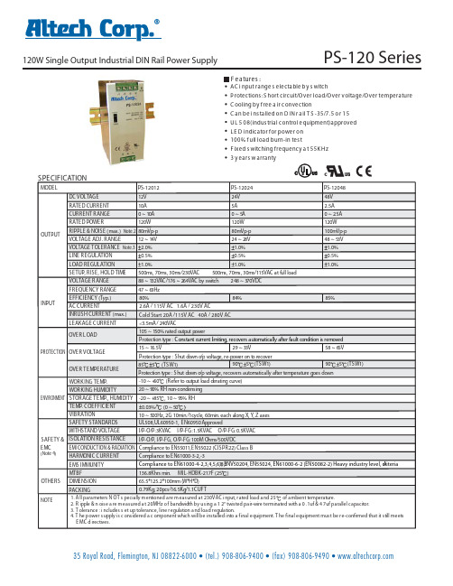
PS-120 Series
100
125.2
115VAC 230VAC TB2 1 2 3 4 LE D
+V ADJ.
TB1 1 2 3
ADMISSIBLE DIN-RAIL:TS35/7.5 OR TS35/15
Terminal Pin. No Assignment (TB1)
Protection type : Shut down o/p voltage, recovers automatically after temperature goes down -10 ~ + 60 (Refer to output load derating curve) 20 ~ 90% RH non-condensing -20 ~ + 85 , 10 ~ 95% RH 0.03%/ (0 ~ 50 10 ~ 500Hz, 2G 10min./1cycle, 60min. each along X, Y, Z axes UL508, UL60950-1, EN60950 Approved I/P-O/P:3KVAC I /P-FG:1.5KVAC O/P-FG:0.5KVAC
OTHERS
NOTE
DIMENSION PACKING
STMicroelectronics STPS10M120SF 高频微型DC DC转换器接线板芯片说

STPS10M120SFFeatures•Low profile design – package height of 1.1 mm typ.•Wettable flanks for automatic visual inspection •Low forward voltage drop •Avalanche capability •ECOPACK ®2 compliantApplications•Switching diode •DC / DC converter •LED Lighting •SMPS•Secondary rectification •Auxiliary powerDescriptionThis high voltage Schottky barrier rectifier has been optimized for use in highfrequency miniature DC/DC converters, reverse battery protection, battery chargers and adaptors.Packaged in PSMC (TO-277A), the STPS10M120SF provides a high level ofperformance in a compact and flat package which can withstand very high operating junction temperature.120 V power Schottky rectifierSTPS10M120SFDatasheetSTPS10M120SFCharacteristics 1CharacteristicsTable 1. Absolute ratings (limiting values at 25 °C, unless otherwise specified, anode terminals short-circuited)1.(dP tot/dT j) < (1/R th(j-a)) condition to avoid thermal runaway for a diode on its own heatsink.Table 2. Thermal resistance parametersFor more information, please refer to the following application note:•AN5088: Rectifiers thermal management, handling and mounting recommendationsTable 3. Static electrical characteristics (anode terminals short-circuited)1.Pulse test: t p = 5 ms, δ < 2%2.Pulse test: t p = 380 µs, δ < 2%To evaluate the conduction losses, use the following equation:P = 0.53 x I F(AV) + 0.014 x I F2(RMS)For more information, please refer to the following application notes related to the power losses:•AN604: Calculation of conduction losses in a power rectifier•AN4021: Calculation of reverse losses in a power diodeSTPS10M120SFCharacteristics (curves) 1.1Characteristics curvesFigure 7. Thermal resistance junction to ambient versus copper surface under tab (typical values, epoxyprinted board FR4, e Cu= 35 µm) (PSMC (TO-277A))020406080100120012345678910STPS10M120SFCharacteristics (curves)2Package informationIn order to meet environmental requirements, ST offers these devices in different grades of ECOPACK ®packages, depending on their level of environmental compliance. ECOPACK ® specifications, grade definitions and product status are available at: . ECOPACK ® is an ST trademark.2.1PSMC (TO-277A) package information•Epoxy meets UL94,V0•Cooling method : by conduction (C)Figure 8.PSMC (TO-277A) package outlineSTPS10M120SFPackage informationSTPS10M120SFPSMC (TO-277A) package information Table 4. PSMC (TO-277A) package mechanical dataFigure 9. PSMC (TO-277A) package footprint in mm (in inches)STPS10M120SFOrdering information 3Ordering informationTable 5. Ordering informationSTPS10M120SFRevision historyTable 6. Document revision historySTPS10M120SFIMPORTANT NOTICE – PLEASE READ CAREFULLYSTMicroelectronics NV and its subsidiaries (“ST”) reserve the right to make changes, corrections, enhancements, modifications, and improvements to ST products and/or to this document at any time without notice. Purchasers should obtain the latest relevant information on ST products before placing orders. ST products are sold pursuant to ST’s terms and conditions of sale in place at the time of order acknowledgement.Purchasers are solely responsible for the choice, selection, and use of ST products and ST assumes no liability for application assistance or the design of Purchasers’ products.No license, express or implied, to any intellectual property right is granted by ST herein.Resale of ST products with provisions different from the information set forth herein shall void any warranty granted by ST for such product.ST and the ST logo are trademarks of ST. All other product or service names are the property of their respective owners.Information in this document supersedes and replaces information previously supplied in any prior versions of this document.© 2018 STMicroelectronics – All rights reservedSTPS10M120SF。
MITSUBISHI PM100RSE120 数据手册

INSULATED PACKAGEINSULATED PACKAGEINSULATED PACKAGEInverter partV D = 15V (Fig. 5,6)Break part–20 ≤ T j ≤ 125°C, V D = 15V(Fig. 5,6)–20≤ T j ≤ 125°C, V D = 15V (Fig. 5,6)V D = 15V (Fig. 5,6)CONTROL PART(Note-3)Fault output is given only when the internal OC, SC, OT & UV protection.Fault output of OT protection operate by lower arm.Fault output of OC, SC protection given pulse.Fault output of OT, UV protection given pulse while over level.—————V CE(sat)I CESV FM V mAMin.Typ.Max.V Collector-Emitter Saturation Voltage FWDi Forward Voltage Collector-Emitter Cutoff CurrentI F = 50A(Fig. 2)T j = 25°CT j = 125°CUnit ParameterSymbol Test ConditionLimits 3.303.253.51102.652.602.5——T j = 25°CT j = 125°CBRAKE PARTV D = 15V , I C = 50A V CIN = 0V , Pulsed (Fig. 1)V CE = V CES , V CIN = 15V(Fig. 4)3.53.5————Main terminal screw : M5Mounting partscrew : M5—Symbol ParameterMounting torque Mounting torque WeightTest ConditionUnit N • m N • m gLimits Min.Typ.Max.2.52.5—3.03.0920MECHANICAL RATINGS AND CHARACTERISTICSI D Circuit CurrentInput ON Threshold Voltage Input OFF Threshold Voltage Over Current Trip LevelShort Circuit Trip Level Over Current Delay Time Over Temperature Protection Supply Circuit Under-Voltage ProtectionFault Output Current Minimum Fault Output Pulse WidthV th(on)V th(off)OCSC t off(OC)OT OT r UV UV r I FO(H)I FO(L)t FOParameterSymbol Trip level Reset level Trip levelReset level °C V mA ms 82201.82.3——————125—12.5—0.0115—mA ——1.21.722814575———111—11.5———1.0Max.Min.Typ.Unit Limits 60151.52.0345——3401441011810012.012.5—101.8Vµs AA Inverter partBrake partV D = 15V , V CIN = 15VApplied between :U P -V UPC , V P -V VPC , W P -V WPCU N • V N • W N • B r -V NC Test ConditionBase-plateTemperature detection, V D = 15V–20 ≤ T j ≤ 125°CV D = 15V , V FO = 15V (Note-3)V D = 15V(Note-3)V N1-V NC V XP1-V XPCT j = 25°C T j = 125°C RECOMMENDED CONDITIONS FOR USERecommended valueUnit Test ConditionSymbol ParameterV Applied across P-N terminalsApplied between :V UP1-V UPC , V VP1-V VPCV WP1-V WPC , V N1-V NC (Note-4)Applied between :U P -V UPC , V P -V VPC , W P -V WPCU N • V N • W N • B r -V NCUsing Application Circuit input signal of IPM, 3φsinusoidal PWM VVVF inverter (Fig. 8)For IPM ’s each input signals(Fig. 7)Supply Voltage Control Supply Voltage Input ON Voltage Input OFF Voltage PWM Input Frequency Arm Shoot-through Blocking Time≤ 80015±1.5≤ 0.8≥ 4.0≤ 20≥ 3.0V CC V CIN(on)V CIN(off)f PWM t deadV D V kHz µsV (Note-4)Allowable Ripple rating of Control Voltage : d v /d t ≤ ±5V/µs, 2V p-pINSULATED PACKAGEINSULATED PACKAGE。
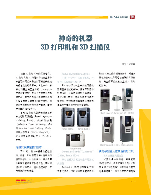
神奇的机器3D打印机和3D扫描仪
IM3D Print 科普专栏撰文/杨启森随着3D 打印技术的逐渐普及,3D 打印机和3D 扫描仪作为行业中十分重要的两类产品也如雨后春笋般地出现在我们的视野中。
由北京市计算中心和震旦集团主办的“2016年3D 打印科普行动”展示了许多技术成熟神奇的机器3D 打印机和3D 扫描仪FDM 技术实现的超精细细节。
凭借多样化的色彩以及可轻松去除的支撑材料,完全颠覆传统意义上对3D 打印的期待。
DimensionEliteDimension BST 1200esDimensionSST 1200es Fortus 250mcFortus 380mc/450mc/900mc 无需“生产线”的制造系统,行业领先的高性能技术支持Fortus 系列3D 生产系统可提供耐用且高精度的部件,具有可预见的机械性能、化学特性和热力学特性。
Fortus 380mc Fortus 450mcFortus 900mcDimensionElite/BST 1200es/SST 1200es、Fortus 250mc打印未来3D的表面扫描零件的横截面形状,在紫外激光的光束照射下的树脂固化形成扫描形状的零件横截层,结合在之前形成的零件横截层上。
SL200/300/450/500/660中瑞科技光固化技术的最大的优点是精度高,其精密程度甚至无法用肉眼或触觉来分辨。
同时,还可对光固化样机可进行机加工,可用在注射成型、热成型、吹塑和各种金属铸造过程。
SL 200SL 300SL 450来了灵活性和美观。
基于PolyJet 3D打印技术,这些系统可提供令人惊异的表面光滑度、精致的细节和最为丰富的材料特性。
Objet 260Connex1/2/3Objet 350Connex1/2/3Objet 500Connex1/2/3Objet 1000 PlusObjet 24/30/30pro/30primeObjet 24Objet 30Objet 30 Pro Objet 30PrimeObjet Eden 260VS完美精准的个性化解决方案基于Stratasys先进的PolyJet技术,Objet Eden系统能够打印出拥有超精细细节和复杂几何结构的0.6mm厚薄壁的模型,适用于牙科和医疗器具的专业材料打印。
120series-IM-TS UE温度开关说明书中文

安装与维护说明书
安装维护前,请先通读说明书,并参阅最后一页推荐的操作、保修、厂家责任。
概述
错误的使用此项产品会导致爆炸及人员伤亡。在安装 前一定要仔细阅读并理解此产品的性能及特点以确保 使用的安全。
这个设备仅只能用于 CLASS I,DIVISIONS 1 & 2, GROUPS B,C 以及 D;CLASS II,DIVISIONS 1 & 2,GROUPS E, F 和 G;CLASS III, 或是非危险情况的区域。
注意事项: 美国联合电器控制公司推荐在选择和安装UE压力和 温度控制的过程中注意下列的事项。在安装前,必须 详细阅读和理解安装和维护说明。 1.为了避免损害器件,耐压和最高温度不能超过说
明书内允许的范围,即使是短暂的过程中。操作 中可以允许在启动和测试时达到最大压力和最高 温度,但是在连续操作中,,一定要严格安装范 围制定的数据来操作。长时间的工作在最大压力 和最高温度下会减小传感器的寿命。 2.一个备用件在恶劣环境应用中非常必要,如元件 的损坏可能会危及到生命和财产,或高低限的失 控将导致系统崩溃。 3.必须要注意控制器量程的选择,确保在无意甚至 有意的情况下的设定值错误选择也不会导致系统 安全上有隐患。 4.在震动,冲击的地方或者温度变化大的地方不会 损害或影响控制器,但是在潮湿的地方要将入口 点密封起来防止湿气的进入。 5.出货后禁止改变或修整元件,如果必须更改,必 须先要和UE公司咨询。 6.要注意对元件的监控,注意元件是否有设定点飘 移或者显示错误的情况发生,如果有,立刻要对 元件进行检查。 7.对元件进行预防性的维护和定期的检查是很重要 的,可以检查元件是否有损害,这些可能会危及 到财产和人员安全。 8.对于所有的元件,在使用前都必须检查出厂设置。 9.说明书中规定的额定功率一定不能超过。超载将 会对元件进行损害。电线单元一定要安照当地或 国际的标准选择正确的型号安装。 10. 不要把元件安装在一个环境温度超过说明书制 定范围的环境中 质量保证体系: 在质保期间,如果材料或者工艺出现的问题,将由出 售者负责免费维修或者更换。但是这些服务只限于从 购买产品起的36个月内。
希斯特电动货车S1.0E和S1.2E系列技术指南说明书
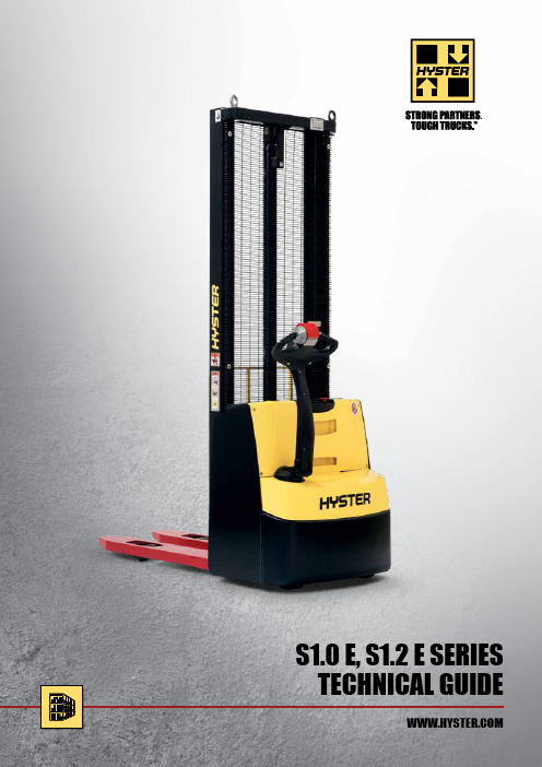
S1.0 E, S1.2 E SERIES TECHNICAL GUIDES1.0 E, S1.2 E1-11-21-3NOTE:Specifications are affected by the condition of the vehicle and how it is equipped, as well as the nature and condition of the operating area. Inform your dealer of the nature and condition of the intended operating area when purchasing your Hyster T ruck.(1)These values may vary of +/-5%.(2)A vailable batteries 24V / 150Ah (144 kg) ; 24V / 200Ah Polypropylene case version (160 kg) ; 24V / 150Ah Polypropylenecase version (125 kg)(3)Available batteries 24V / 200Ah Polypropylene case version (160 kg)(4)W ith 2 stg mast and b5=570mm the s dimension increases 5mm for first 250mm at toe(5)These values are with loadbackrest up(6)These values are with loadbackrest down(7)Available battery 24V / 100Ah Li-Ion (144 kg)(8)Available battery 24V / 200Ah Li-Ion (154 kg)MAST TABLES(1)With free lift of 100 mm.(2)All weights are: mast structures (weldment, cylinders, chain, pulley) + oil. EXCLUDED: forks, accessories(3)With optional load backrest value is increased of 585mm Specification data is based on VDI 2198 NOTICECare must be exercised when handling elevated loads. When the carriage and/ or load is elevated, truck stability is reduced. It is important that the mast tilt in either direction is kept to a minimum when loads are elevated. Operators must be trained and must read, understand and follow the instructions contained in the Operating Manual. All values are nominal values and they are subject to tolerances. For further information, please contact the manufacturer. Hyster products are subject to change without notice. Lift trucks illustrated may feature optional equipment. Values may vary with alternative configurations.Safety: This truck conforms to thecurrent EU requirements.3Lift Height (1) h 3 (mm)Height, mast loweredh 1 (mm)Height, mast extended (3)h 4 (mm)Weight (2) (kg)S 1.0 E S 1.2 E144019001945120164021002145127184023002345135204025002545142Lift height h 3 (mm)Free lift h 2 (mm) Height, mast lowered (1)h 1 (mm)Height, mast extended (3)(mm)Weight (2)(kg) S 1.2 ES 1.0 E238010017502890188258010018503090196278010019503290203298010020503490210318010021503690218338010022503890225358010023504090233378010024504290239398010025504490256418010026504690263www.hyster.eu*********************/HysterEurope@HysterEurope/HysterEuropeSTRONG PARTNERS. TOUGH TRUCKS.TMFOR DEMANDING OPERATIONS, EVERYWHERE.Hyster supplies a complete range of warehouse equipment, IC and electric counterbalanced trucks, container handlers and reach stackers. Hyster is committed to being much more than a lift truck supplier.Our aim is to offer a complete partnership capable ofresponding to the full spectrum of material handling issues: Whether you need professional consultancy on your fleet management, fully qualified service support, or reliable parts supply, you can depend on Hyster.Our network of highly trained dealers provides expert, responsive local support. They can offer cost-effective finance packages and introduce effectively managedmaintenance programmes to ensure that you get the best possible value. Our business is dealing with your material handling needs so you can focus on the success of your business today and in the future.HYSTER-YALE UK LIMITED trading as Hyster Europe. Registered Address: Centennial House, Building 4.5, Frimley Business Park, Frimley, Surrey GU16 7SG, United Kingdom.Registered in England and Wales. Company Registration Number: 02636775.©2020 HYSTER-YALE UK LIMITED, all rights reserved. HYSTER, , and STRONG PARTNERS. TOUGH TRUCKS. are trademarks of HYSTER-YALE Group, Inc.NDIIThane is a trademarks of Wicke GmbH + Co. KG.Hyster products are subject to change without notice. Forklift trucks illustrated may feature optional equipment.Printed in EU. Part number: 3990177 Rev. 08-04/20-TLCHYSTER EUROPECentennial House, Frimley Business Park, Frimley, Surrey, GU16 7SG, England.Tel: +44 (0) 1276 538500。
西博思电动门技术资料
8 9 10 11 12-16 17 18 19 20-24 25 26 27 27 28-29 30 31-48 49 50 50 51 52-68 69 70-72 73-74 75-78 80
stps20s100ct参数
stps20s100ct参数(最新版)目录1.概述 STPS20S100CT 参数2.STPS20S100CT 的主要参数3.参数详解4.参数应用场景正文【概述 STPS20S100CT 参数】STPS20S100CT 是一种电子元器件的参数,常用于描述其性能、功能和规格等。
了解 STPS20S100CT 参数有助于我们更好地选择和使用这种元器件,确保其在各种应用场景下都能发挥出最佳性能。
【STPS20S100CT 的主要参数】STPS20S100CT 的主要参数包括以下几个方面:1.类型:STPS20S100CT 是一种二极管参数。
2.额定电压:该参数表示二极管能承受的最高电压。
3.额定电流:该参数表示二极管能承受的最大电流。
4.封装形式:封装形式是指二极管的外形和结构,包括有引脚、无引脚等不同形式。
5.工作温度:该参数表示二极管能在哪些温度范围内正常工作。
【参数详解】以下是 STPS20S100CT 参数的详细解释:1.类型:STPS20S100CT 是一种常见的二极管参数,表示该二极管的结构、材料和性能等。
2.额定电压:STPS20S100CT 的额定电压为 100V,意味着该二极管能承受的最高电压为 100 伏特。
在实际应用中,如果电压超过该值,二极管可能会损坏。
3.额定电流:STPS20S100CT 的额定电流为 20 安培,表示该二极管能承受的最大电流为 20 安培。
超过该电流值,二极管可能会过热、损坏甚至烧毁。
4.封装形式:STPS20S100CT 的封装形式可能包括有引脚、无引脚等不同形式。
封装形式影响二极管的稳定性、可靠性和散热性能等,因此需要根据实际应用场景选择合适的封装形式。
5.工作温度:STPS20S100CT 的工作温度范围为 -40℃至 +125℃,表示该二极管能在这个温度范围内正常工作。
温度过高或过低可能会影响二极管的性能、寿命和可靠性等。
【参数应用场景】STPS20S100CT 参数广泛应用于各种电子设备和产品中,如电源、放大器、电视机、收音机等。
proteus元件对照表(经典详细)

proteus元件对照表(经典详细)proteus常用元件中英文对照表元件名称中文名说明7407 驱动门1N914 二极管74Ls00 与非门74LS04 非门74LS08 与门74LS390 TTL 双十进制计数器7SEG 4针BCD-LED 输出从0-9 对应于4根线的BCD码7SEG 3-8译码器电路BCD-7SEG转换电路ALTERNATOR 交流发电机AMMETER-MILLI mA安培计AND 与门BATTERY 电池/电池组BUS 总线CAP 电容CAPACITOR 电容器CLOCK 时钟信号源CRYSTAL 晶振D-FLIPFLOP D触发器FUSE 保险丝GROUND 地LAMP 灯LED-RED 红色发光二极管LM016L 2行16列液晶可显示2行16列英文字符,有8位数据总线D0-D7,RS,R/W,EN三个控制端口(共14线),工作电压为5V。
没背光,和常用的1602B功能和引脚一样(除了调背光的二个线脚)LOGIC ANALYSER 逻辑分析器LOGICPROBE 逻辑探针LOGICPROBE[BIG] 逻辑探针用来显示连接位置的逻辑状态LOGICSTATE 逻辑状态用鼠标点击,可改变该方框连接位置的逻辑状态LOGICTOGGLE 逻辑触发MASTERSWITCH 按钮手动闭合,立即自动打开MOTOR 马达OR 或门POT-LIN 三引线可变电阻器POWER 电源RES 电阻RESISTOR 电阻器SWITCH 按钮手动按一下一个状态SWITCH-SPDT 二选通一按钮VOLTMETER 伏特计VOLTMETER-MILLI mV伏特计VTERM 串行口终端Electromechanical 电机Inductors 变压器Laplace Primitives 拉普拉斯变换Memory IcsMicroprocessor IcsMiscellaneous 各种器件AERIAL-天线;ATAHDD;ATMEGA64;BATTER Y;CELL;CRYSTAL-晶振;FUSE;METER-仪表;Modelling Primitives 各种仿真器件是典型的基本元器模拟,不表示具体型号,只用于仿真,没有PCBOptoelectronics 各种发光器件发光二极管,LED,液晶等等PLDs & FPGAsResistors 各种电阻Simulator Primitives 常用的器件Speakers & SoundersSwitches & Relays 开关,继电器,键盘Switching Devices 晶阊管Transistors 晶体管(三极管,场效应管)TTL 74 seriesTTL 74ALS seriesTTL 74AS seriesTTL 74F seriesTTL 74HC seriesTTL 74HCT seriesTTL 74LS seriesTTL 74S seriesAnalog Ics 模拟电路集成芯片Capacitors 电容集合CMOS 4000 seriesConnectors 排座,排插Data Converters ADC,DACDebugging Tools 调试工具ECL 10000 SeriesDevice.lib 包括电阻、电容、二极管、三极管和PCB的连接器符号ACTIVE.LIB 包括虚拟仪器和有源器件DIODE.LIB 包括二极管和整流桥DISPLAY.LIB 包括LCD、LEDBIPOLAR.LIB 包括三极管FET.LIB 包括场效应管ASIMMDLS.LIB 包括模拟元器件VALVES .LIB 包括电子管ANALOG.LIB 包括电源调节器、运放和数据采样IC CAPACITORS.LIB 包括电容COMS.LIB 包括4000系列ECL.LIB 包括ECL10000系列MICRO.LIB 包括通用微处理器OPAMP.LIB 包括运算放大器RESISTORS.LIB 包括电阻FAIRCHLD .LIB 包括FAIRCHLD 半导体公司的分立器件LINTEC.LIB 包括LINTEC公司的运算放大器NATDAC.LIB 包括国家半导体公司的数字采样器件NATOA.LIB 包括国家半导体公司的运算放大器TECOOR.LIB 包括TECOOR公司的SCR 和TRIACTEXOAC.LIB 包括德州仪器公司的运算放大器和比较器ZETEX .LIB 包括ZETEX 公司的分立器件分立元件库元件名称及中英对照AND 与门ANTENNA 天线BATTERY 直流电源BELL 铃,钟BVC 同轴电缆接插件BRIDEG 1 整流桥(二极管) BRIDEG 2 整流桥(集成块) BUFFER 缓冲器BUZZER 蜂鸣器CAP 电容CAPACITOR 电容CAPACITOR POL 有极性电容CAPVAR 可调电容CIRCUIT BREAKER 熔断丝COAX 同轴电缆CON 插口CRYSTAL 晶体整荡器DB 并行插口DIODE 二极管DIODE SCHOTTKY 稳压二极管DIODE VARACTOR 变容二极管DPY_3-SEG 3段LEDDPY_7-SEG 7段LEDDPY_7-SEG_DP 7段LED(带小数点)ELECTRO 电解电容FUSE 熔断器INDUCTOR 电感INDUCTOR IRON 带铁芯电感INDUCTOR3 可调电感JFET N N沟道场效应管JFET P P沟道场效应管LAMP 灯泡LAMP NEDN 起辉器LED 发光二极管METER 仪表MICROPHONE 麦克风MOSFET MOS管MOTOR AC 交流电机MOTOR SERVO 伺服电机NAND 与非门NOR 或非门NOT 非门NPN NPN 三极管NPN-PHOTO 感光三极管OPAMP 运放OR 或门PHOTO 感光二极管PNP 三极管NPN DAR NPN三极管PNP DAR PNP三极管POT 滑线变阻器PELAY-DPDT 双刀双掷继电器RES1.2 电阻RES3.4 可变电阻RESISTOR BRIDGE ? 桥式电阻RESPACK ? 电阻SCR 晶闸管PLUG ? 插头PLUG AC FEMALE 三相交流插头SOCKET ? 插座SOURCE CURRENT 电流源SOURCE VOLTAGE 电压源SPEAKER 扬声器SW ? 开关SW-DPDY ? 双刀双掷开关SW-SPST ? 单刀单掷开关SW-PB 按钮THERMISTOR 电热调节器TRANS1 变压器TRANS2 可调变压器TRIAC ? 三端双向可控硅TRIODE ? 三极真空管VARISTOR 变阻器ZENER ? 齐纳二极管DPY_7-SEG_DP 数码管SW-PB 开关元件名称中文名说明7407 驱动门1N914 二极管74Ls00 与非门74LS04 非门74LS08 与门74LS390 TTL 双十进制计数器7SEG 4针BCD-LED 输出从0-9 对应于4根线的BCD码7SEG 3-8译码器电路BCD-7SEG转换电路ALTERNATOR 交流发电机AMMETER-MILLI mA安培计AND 与门BATTERY 电池/电池组BUS 总线CAP 电容CAPACITOR 电容器CLOCK 时钟信号源CRYSTAL 晶振D-FLIPFLOP D触发器FUSE 保险丝GROUND 地LAMP 灯LED-RED 红色发光二极管LM016L 2行16列液晶可显示2行16列英文字符,有8位数据总线D0-D7,RS,R/W,EN三个控制端口(共14线),工作电压为5V。
Kongsberg TOPAS PS120 参数子底探测器说明书
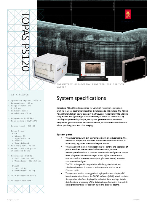
482731/APARAMETRIC SUB-BOTTOM PROFILER FOR SHALLOW WATERSSystem specificationsKongsberg TOPAS PS120 is designed for very high-resolution sub-bottomprofiling in water depths from less than 2 meters up to 500 meters. The TOPAS PS 120 transmits high power signals in the frequency range from 70 to 100 kHz using a small and light-weight transducer array of only 32x42 cm and 13 kg. Utilizing the parametric principle, the system generates low sub-bottomfrequencies @2-30 kHz with very narrow beams, no side lobes and wide band width, providing clear and crisp imaging.System parts•Transducer array with 6x4 elements and 15m transducer cable. The transducer may be hull mounted or fixed temporarily to the hull in other ways, e.g. by an over-the-side pole mount.•Transceiver unit cabinet with electronics for control and operation of power amplifier, the data acquisition electronics, and thetransmit/receive switch. It controls the transmitted signature, output level, ping rate and transmit angles. It has digital interfaces for external vertical reference sensor (roll, pitch and heave) as well as synchronization signal.The TRU is designed to be portable with integrated shock and vibration absorbers. It connects to the operator station via an Ethernet cable.•The operator station is a ruggedized high-performance Laptop PC-based workstation. It runs the TOPAS software (MMI), which contains the operator interface, displays the collected data, and logs data to disk. Realtime processing of the data is also performed in this unit. It has digital interfaces for position input and external depths.AT A GLANCE• Operating depths: 2-500 m • Penetration: >50 m • Range resolution:0.5-4 cm• Sediment layerresolution: <5 cm• Frequency: 2-30 kHz • Beam width: ±(1.5°x2°)• Source level: 208 dB• Pulse typeso CWo Linear FMo Hyperbolic FM o Rickero User defined• Max ping rate: 40 Hz • Heave, roll and pitchstabilized beams• Dimensions (DxWxH)o TRU: 70x53x40 cmo Transducer: 32x42x7 cm• Weight:o TRU: 45 kgo Transducer: 13 kg• 15 m transducer cable• PC-based platformTOPAS PS120Kongsberg Maritime AS Phone: +47 32 02 38 00 P.O. Box 111N-3191 Horten, Norway********************Penetration performance depends on sediment characteristics, water depth, transmitted signature etc. With PS120 a demonstrated penetration of more than 50 meters can be achieved in water depths up to more than 400 meters with a range resolution of typically better than 5 cm.The powerful TOPAS MMI software for realtime acquisition, as well as offline replay and processing. TOPAS PS120 operator station is a ruggedized laptopPS120 transducer – outline dimensionsPS120 transceiver unit – outline dimensions (lids removed)T O P A S P S 120 T E C H N I C A L S P E C I F I C A T I O N SPrimary source level (max)>238 dB // μPa @ 1 meterSecondary signal source level >202 dB @12 kHz // μPa @ 1 meter >208 dB @20 kHz // μPa @ 1 meterPulse typesRicker, CW (Continuous Wave), Linear FM, Hyperbolic FM, user defined Pulse lengths 0.01 – 30 ms, adjustableBeam widthPrimary: 3x4°, Secondary: ~4x5° Range resolution <0.05 mElectronic beam steering Across: 12° Along: 8°Ping rate Up to 40 pings per second Ping modesMultipulse mode, burst mode Heave, roll and pitchcompensation Yes (depending on external sensor inputData acquisition digital 24 bit @ 192 kHz sample rate; SLF full-waveform sub-bottom data Auxiliary input GNSS, EM® multibeam echo sounder depth, attitude, trigger Data export formatsTOPAS raw data format SEGYReal time processing capabilitiesDigital band-pass filterSpiking deconvolution filter Matched filterTime Varying Filter (TVF) DereverberationTime Variable Gain (TVG)Automatic Volume Control (AVC) Stacking (Trace mixing) Swell filterManual/automatic gain Attribute processing StatisticsPower Spectral Density (PSD) display Replay and processingIncluded in the acquisition software TOPAS MMIPower supply TRU 220 to 240 VAC, <1kW, 47-63 Hz Top side unit size and weight 0.53 m x 0.7 m x 0.4 m // 45 kg Transducer array size and weight0.32 m x 0.42 m x 0.07 m // 13 kg。
TFS140E中文资料
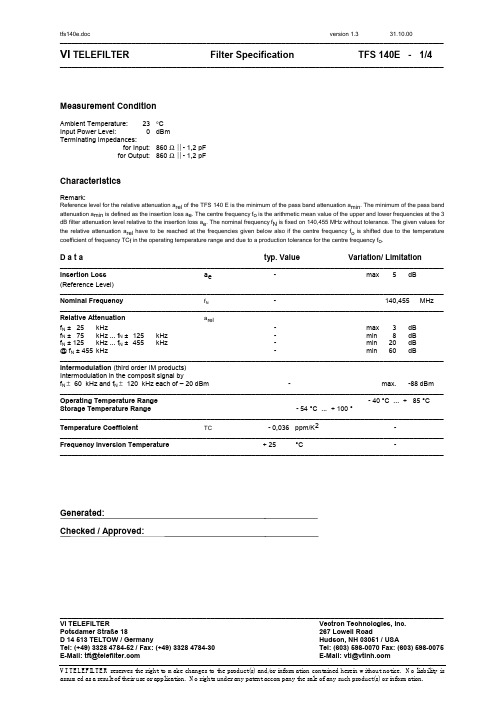
TFS 140 E tft L5
-
Pin 4 - Output Pin 5 - Output RF Return Pin 9 - Input Pin 10 - Input RF Return Pin 1,2,3,6,7,8 - Ground
Generated: Checked / Approved:
______________________________________________________________________________________________________ VI TELEFILTER Vectron Technologies, Inc. Potsdamer Straße 18 267 Lowell Road D 14 513 TELTOW / Germany Hudson, NH 03051 / USA Tel: (+49) 3328 4784-52 / Fax: (+49) 3328 4784-30 Tel: (603) 598-0070 Fax: (603) 598-0075 E-Mail: tft@ E-Mail: vti@ VI TELEFILTER reserves the right to make changes to the product(s) and/or information contained herein without notice. No liability is assumed as a result of their use or application. No rights under any patent accompany the sale of any such product(s) or information.
PET120中文标准说明书
JWS120系列PET片材塑料挤出机电脑控制系统用户手册上海金纬电气自动化设备制造有限公司二OO六年十月目录一、公司简介------------------------------------3二、概述----------------------------------------3三、电气配置------------------------------------4四、电脑屏操作----------------------------------6五、辅机部分------------------------------------20六、安装及注意事项------------------------------21七、故障及报警排出------------------------------23附录:电气原理图备注:1、本操作说明书为JWS120通用型说明书,因各设备差异导致与说明书不尽相同的地方实属正常。
2、因设备的改进将不会及时通知相关客户,请谅解。
3 本说明书解释权归金纬机械公司所有。
一、公司简介上海金纬电气自动化设备制造有限公司是国内为数不多的机电一体化的专业制造公司,主要服务对象为世界各地的直接用户,以及无电气成套部门的机械制造公司.公司以业内技术创新为前锋,以国外技术为外援,以全球计数服务为后卫的经营宗旨,推动中国制造业的发展.多年来,公司以现代领先自动化技术为核心,以系统设计,采购,安装,调试,维护为手段服务于国内外的广大客户.在橡塑机械,化纤纺织机械,水处理,造纸机械,印刷机械等领域中赢得数以万计客户的青睐和好评.目前德国西门子,瑞士ABB,日本安川,富士,欧盟的施耐德和丹佛斯等跨国公司已经成为我公司的重要合作伙伴.金纬电气成套产品设备遍布国内和俄罗斯,土耳其,西班牙,法国,墨西哥,加拿大,新西兰,越南,印度,韩国,伊朗等50多个国家和地区."快速有序,用心持久"是电气公司的企业精神,是全体员工的努力方向,我们本着热情为客户服务的态度,不断追求产品的完美如一,保证产品使用的可靠,简便,运用新技术,不断创新,走专业服务型的企业之路.二、概述JWS120系列片材挤出机主要分为主机和三辊辅机两大部分。
stps20s100ct参数
stps20s100ct参数【1】STPS20S100CT参数简介STPS20S100CT是一种电力电子器件,其参数包括:STP(Surface Mounted Package,表面贴装封装)、20A(最大电流)、S100(电容器容量为100uF)和CT(无铁芯电感)。
这些参数代表了器件的类型、电流容量和电感特性。
【2】参数的具体含义和作用1.STP:表面贴装封装,意味着这款器件采用表面贴装技术(SMT)制造,具有体积小、重量轻、可靠性高等优点。
2.20A:最大电流,表示该器件能承受的最大电流为20A。
在选择器件时,应根据电路需求选择合适的电流规格,以确保器件的安全稳定运行。
3.S100:电容器容量为100uF,表示这款器件具有一定的储能能力。
在实际应用中,可以根据电路需求选择相应容值的电容器,以满足储能和滤波等需求。
4.CT:无铁芯电感,意味着这款器件具有高品质因数、低损耗和高稳定性等特点。
无铁芯电感在电力电子领域具有广泛的应用,如逆变器、整流器和滤波器等。
【3】如何应用这些参数1.根据电路需求,选择合适的STP20S100CT参数。
例如,若电路需要承受较大电流,可选择20A电流规格的器件。
2.考虑电容器容量S100uF的作用。
在需要储能和滤波的场合,应选择适当容值的电容器,以满足电路性能要求。
3.无铁芯电感CT有助于提高电路的稳定性和降低损耗。
在设计电力电子装置时,可优先考虑使用无铁芯电感。
【4】总结STPS20S100CT参数代表了这款电力电子器件的类型、电流容量和电感特性。
了解这些参数的含义和作用,有助于我们更好地选择和使用这类器件。
在实际应用中,应根据电路需求,合理选择参数,确保器件的安全稳定运行。
EPA120E资料
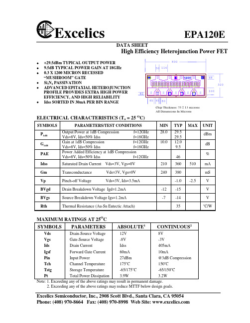
ExcelicsEPA120EDATA SHEETHigh Efficiency Heterojunction Power FET• +29.5dBm TYPICAL OUTPUT POWER • 9.5dB TYPICAL POWER GAIN AT 18GHz • 0.3 X 1200 MICRON RECESSED “MUSHROOM” GATE • Si 3N 4 PASSIVATION• ADVANCED EPITAXIAL HETEROJUNCTION PROFILE PROVIDES EXTRA HIGH POWER EFFICIENCY, AND HIGH RELIABILITY • Idss SORTED IN 30mA PER BIN RANGEELECTRICAL CHARACTERISTICS (T a = 25 O C)SYMBOLS PARAMETERS/TEST CONDITIONS MIN TYP MAX UNITP 1dB Output Power at 1dB Compression f=12GHz Vds=8V, Ids=50% Idss f=18GHz 28.029.529.5 dBm G 1dB Gain at 1dB Compression f=12GHz Vds=8V, Ids=50% Idss f=18GHz 10.0 12.0 9.5 dB PAE Power Added Efficiency at 1dB Compression Vds=8V, Ids=50% Idss f=12GHz 46 % Idss Saturated Drain Current Vds=3V, Vgs=0V 210 360 510 mA Gm Transconductance Vds=3V, Vgs=0V 240 380 mS Vp Pinch-off Voltage Vds=3V, Ids=3.5mA -1.0 -2.5 V BVgd Drain Breakdown Voltage Igd=1.2mA -12 -15 V BVgs Source Breakdown Voltage Igs=1.2mA -7 -14 V RthThermal Resistance (Au-Sn Eutectic Attach)35oC/WMAXIMUM RATINGS AT 25O C SYMBOLS PARAMETERS ABSOLUTE 1 CONTINUOUS 2Vds Drain-Source Voltage 12V 8V Vgs Gate-Source Voltage -8V -3V Ids Drain Current Idss 405mA Igsf Forward Gate Current 60mA 10mA Pin Input Power 27dBm @3dB Compression Tch Channel Temperature 175o C 150o C Tstg Storage Temperature -65/175o C -65/150o C Pt Total Power Dissipation3.9W 3.2WNote: 1. Exceeding any of the above ratings may result in permanent damage.2. Exceeding any of the above ratings may reduce MTTF below design goals.Excelics Semiconductor, Inc., 2908 Scott Blvd., Santa Clara, CA 95054 Phone: (408) 970-8664 Fax: (408) 970-8998 Web Site: Chip Thickness: 75 ± 13 microns All Dimensions In Microns830320501164810080954045DSGDD D SSSSGGGEPA120EDATA SHEETHigh Efficiency Heterojunction Power FETS-PARAMETERS8V, 1/2 IdssFREQ --- S11 ------ S21 --- --- S12 --- --- S22 --- FREQ --- S11 --- --- S21 --- --- S12 --- --- S22 ---(GHz) MAG ANG MAG ANG MAG ANG MAG ANG (GHz) MAG ANG MAG ANG MAG ANG MAG ANG1.0 0.898 -97.8 14.488 124.9 0.034 39.3 0.300 -95.1 21.0 0.938 162.3 0.751 -2.6 0.036 7.9 0.725 179.62.0 0.885 -134.7 8.805 103.0 0.041 22.6 0.313 -125.6 22.0 0.938 161.2 0.701 -6.4 0.036 6.4 0.743 177.53.0 0.882 -150.7 6.129 90.7 0.042 16.0 0.322 -135.8 23.0 0.939 160.1 0.659 -10.5 0.037 7.6 0.758 175.34.0 0.887 -159.7 4.668 81.9 0.042 10.9 0.338 -140.7 24.0 0.939 159.3 0.622 -14.1 0.039 10.6 0.769 173.45.0 0.896 -165.0 3.747 74.9 0.042 9.3 0.349 -143.7 25.0 0.948 158.8 0.592 -18.1 0.040 12.3 0.776 170.96.0 0.898 -168.8 3.128 68.6 0.040 8.5 0.366 -145.2 26.0 0.946 158.7 0.559 -21.2 0.041 12.6 0.783 168.37.0 0.901 -171.8 2.674 62.8 0.040 7.3 0.390 -146.7 27.0 0.945 158.5 0.535 -24.4 0.044 15.2 0.790 166.08.0 0.904 -174.2 2.329 57.5 0.039 6.7 0.411 -148.1 28.0 0.946 158.0 0.513 -27.1 0.046 16.3 0.791 164.09.0 0.908 -176.0 2.057 52.2 0.037 5.3 0.433 -150.2 29.0 0.958 157.6 0.493 -30.1 0.049 16.5 0.790 161.310.0 0.912 -177.2 1.842 47.7 0.037 5.6 0.458 -152.2 30.0 0.948 156.9 0.472 -33.6 0.050 11.6 0.799 158.511.0 0.916 -178.7 1.657 42.9 0.035 5.4 0.483 -154.7 31.0 0.961 155.8 0.451 -36.8 0.051 12.6 0.802 156.012.0 0.917 -179.9 1.501 38.2 0.035 6.4 0.511 -157.7 32.0 0.955 154.5 0.430 -40.1 0.049 10.4 0.813 152.913.0 0.920 178.8 1.370 33.5 0.033 6.8 0.538 -160.3 33.0 0.951 153.2 0.405 -42.9 0.048 13.5 0.824 150.114.0 0.922 177.5 1.256 28.9 0.033 6.5 0.564 -163.1 34.0 0.959 151.2 0.388 -46.3 0.048 11.3 0.836 147.615.0 0.927 175.6 1.163 24.2 0.033 4.8 0.590 -165.9 35.0 0.963 148.9 0.369 -49.0 0.048 13.2 0.856 144.816.0 0.927 173.8 1.077 19.4 0.033 5.8 0.616 -168.7 36.0 0.967 147.5 0.348 -51.4 0.050 9.7 0.875 141.417.0 0.929 171.4 0.998 14.4 0.033 3.9 0.638 -171.4 37.0 0.978 145.4 0.338 -54.7 0.052 7.8 0.891 138.218.0 0.934 169.1 0.934 9.9 0.034 6.0 0.658 -173.5 38.0 0.993 143.3 0.325 -58.0 0.055 0.1 0.891 134.719.0 0.934 166.8 0.880 5.2 0.034 5.7 0.675 -176.4 39.0 1.005 139.3 0.320 -64.0 0.057 -12.6 0.883 131.920.0 0.936 164.2 0.827 0.5 0.035 4.2 0.692 -178.4 40.0 0.994 137.0 0.312 -67.9 0.058 -21.3 0.876 130.0Note: The data included 0.7 mils diameter Au bonding wires:4 gate wires, 15 mils each; 4 drain wires, 20 mils each; 10 source wires, 7 mils each.。
- 1、下载文档前请自行甄别文档内容的完整性,平台不提供额外的编辑、内容补充、找答案等附加服务。
- 2、"仅部分预览"的文档,不可在线预览部分如存在完整性等问题,可反馈申请退款(可完整预览的文档不适用该条件!)。
- 3、如文档侵犯您的权益,请联系客服反馈,我们会尽快为您处理(人工客服工作时间:9:00-18:30)。
Inches
Min. Typ. Max. Min. Typ. Max.
1.5
1.2
(3x)
2.3
6.4
1.5
4.6
Recommended soldering pattern SOT223
A B C D E F G H I J K L M
2.90 0.60 1.50 0.43 0.50 0.63
6.70 0.248 0.256 0.264 7.30 0.264 0.275 0.287 3.70 0.130 0.139 0.146 0.181 0.090 3.10 0.114 0.118 0.122 0.80 0.023 0.027 0.031 1.70 0.059 0.063 0.067 0.47 0.017 0.018 0.019 0.70 0.019 0.023 0.027 0.67 0.024 0.025 0.026 0.002 0.32 0.012
March 1992
1/3
元器件交易网
STPS120E/STPS130E/STPS140E
ELECTRICAL CHARACTERISTICS STATIC CHARACTERISTICS
Symbol IR ** Tj = 25°C Tj = 100°C VF * Tj = 125°C Tj = 125°C Tj = 25°C IF = 2 A IF = 1 A IF = 2 A Tests Conditions VR = VRRM Min. Typ. Max. 500 10 0.72 0.55 0.81 Unit µA mA V
SOT 223 (Plastic)
Value 1.4 1 10 1 - 65 to + 150 - 65 to + 150 1000 STPS 130E 30 140E 40
Unit A A A A °C V/µs Unit V
THERMAL RESISTANCE
Symbol RTH (j-t) RTH (j-a) Parameter Junction to Tab for D.C Junction to Ambient with 5cm2 Copper Surface Under Tab Total Value 20 55 Unit °C/W
B A 15˚(4x) H 0˚/7˚ I D F J E K L M C
G
Marking : Type number Weight : 0.11 g
Information furnished is believed to be accurate and reliable. However, SGS-THOMSON Microelectronics assumes no responsability for the consequences of use of such information nor for any infringement of patents or other rights of third parties which may results from its use. No license is granted by implication or otherwise under any patent or patent rights of SGS-THOMSON Microelectronics. Specifications mentioned in this publication are subject to change without notice. This publication supersedes and replaces all information previously supplied. SGS-THOMSON Microelectronics products are not authorized for use as critical components in life support devices or systems without express written approval of SGS-THOMSON Microelectonics. © 1994 SGS-THOMSON Microelectronics - All Rights Reserved TURBOSWITCH, TRANSIL, TRISIL, SNUBBERLESS are Trademarks of SGS-THOMSON Microelectronics. SGS-THOMSON Microelectronics GROUP OF COMPANIES Australia - Brazil - France - Germany - Hong Kong - Italy - Japan - Korea - Malaysia - Malta - Morocco - The Netherlands Singapore - Spain - Sweden - Switzerland - Taiwan - Thailand - United Kingdom - U.S.A
1 2 3 4
= = = =
NC K A K
DESCRIPTION Single chip schottky rectifier suited for switchmode power supply and high frequency DC to DC converters. Packaged in SOT 223, this device is intended for surface mounting and use in low voltage, high frequency inverters, free wheeling and polarity protection applications. ABSOLUTE RATINGS (limiting values)
3/3
Pulse test : * tp = 380 µs, duty cycle < 2 % ** tp = 5 ms, duty cycle < 2%
To evaluate the conduction losses use the following equation : P = 0.38 x IF(AV) + 0.17 IF2(RMS) Voltage (V) Marking 20 S12 30 S13 40 S14
2/3
元器件交易网
E/STPS130E/STPS140E
PACKAGE MECHANICAL DATA SOT223
3.3
DIMENSIONS REF. Millimeters
6.30 6.70 3.30 6.50 7.00 3.50 4.60 2.30 3.00 0.70 1.60 0.45 0.60 0.65 0.05
元器件交易网
STPS120E STPS130E STPS140E
SCHOTTKY RECTIFIER
. . . . . .
PRELIMINARY DATASHEET VERY SMALL CONDUCTION LOSSES NEGLIGIBLE SWITCHING LOSSES LOW FORWARD VOLTAGE DROP LOW THERMAL RESISTANCE EXTREMELY FAST SWITCHING SURFACE MOUNTED DEVICE
Symbol IF(RMS) IF(AV) IFSM IRRM Tstg Tj dV/dt Symbol VRRM RMS Forward Current Average Forward Current Surge Non Repetitive Forward Current Peak Repetitive Reverse Current Storage and Junction Temperature Range Critical Rate of Rise of Reverse Voltage Parameter 120E Repetitive Peak Reverse Voltage 20 TL = 135°C δ = 0.5 tp = 10 ms Sinusoidal tp = 2 µs F = 1KHz Parameter