FAR-F6CC-1G6190-L2ZN中文资料
6190说明书
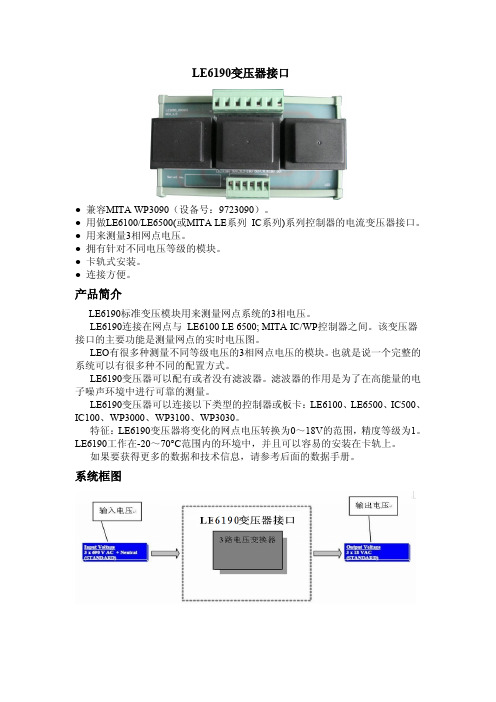
LE6190变压器接口
● 兼容MITA WP3090(设备号:9723090)。
● 用做LE6100/LE6500(或MITA LE系列IC系列)系列控制器的电流变压器接口。
● 用来测量3相网点电压。
● 拥有针对不同电压等级的模块。
● 卡轨式安装。
● 连接方便。
产品简介
LE6190标准变压模块用来测量网点系统的3相电压。
LE6190连接在网点与LE6100 LE 6500; MITA IC/WP控制器之间。
该变压器接口的主要功能是测量网点的实时电压图。
LEO有很多种测量不同等级电压的3相网点电压的模块。
也就是说一个完整的系统可以有很多种不同的配置方式。
LE6190变压器可以配有或者没有滤波器。
滤波器的作用是为了在高能量的电子噪声环境中进行可靠的测量。
LE6190变压器可以连接以下类型的控制器或板卡:LE6100、LE6500、IC500、IC100、WP3000、WP3100、WP3030。
特征:LE6190变压器将变化的网点电压转换为0~18V的范围,精度等级为1。
LE6190工作在-20~70°C范围内的环境中,并且可以容易的安装在卡轨上。
如果要获得更多的数据和技术信息,请参考后面的数据手册。
系统框图
技术数据。
FIREX 辅助设备 - 辅助设备说明书

T h e p r o f e s s i o n a l c h o i c e i n f i r e s a f e t y.FIREX®the recognized leader in residential fire protection, brings you the latest in duct smoke detection technology. FIREX®Duct Smoke Detectors provide early detection of smoke and products of combustion present in air moving through an HVAC duct. These devices are designed for prevention of smoke recirculation in areas by the air handling systems. Fans, blowers, and complete systems may be shut down in the event of smoke detection. Our universal voltage models will operate on any one offour input voltages.Air sampling is accomplished by two tubes, which protrude into the duct. An exhaust tube of one standard length (7'') is provided with each FIREX®Duct Smoke Detector. Intake sampling tubes, which must be ordered separately, are available in three standard lengths.Duct smoke detector mounting is accomplished by the use of a mounting template and four sheet metal screws, which are provided.Duct Smoke DetectorsUniversal Voltage Models230 VAC, 115 VAC, 24 VAC or 24 VDC operation2650-660 Ionization • 2650-661 PhotoelectricHigh Temperature DesignRated to 155˚F (ionization model)for rooftop and other installationswhere high temperatures cancause problems.InterconnectUp to 30 ModelsUp to 30 models can beinterconnected to providecomplete HVAC systemprotection–controlling allconnected blowers, fansand dampers.Alerts When DirtyAutomatically indicates whenmaintenance is required.THR EE Y E ARW AR R A N T YInstallation FlexibilityFast and easy mounting torectangular ducts.Item:2650-660 - 115 Volt AC, 230 Volt AC, 24 Volt AC,or 24 Volt DC ionization2650-661 - 115 Volt AC, 230 Volt AC, 24 Volt ACor 24 Volt DC photoelectric532 - Sampling tube for 6'' to 2.5' duct widths 533 - Sampling tube for 2.5' to 5.0' duct widths 534 - Sampling tube for 5.0' to 10.0' duct widthsPower Requirements:115 Volt AC operation @ 5 mA standby, 15 mA alarm 230 Volt AC operation @ 12 mA standby, 16 mA alarm 24 Volt AC operation @ 20 mA standby, 50 mA alarm 24 Volt DC operation @ 20 mA standby, 50 mA alarmRelay Contact Rating:Alarm contacts, two form “C” rated at 10 Amps @ 230 VAC resistive Trouble contact, one form “C” rated 10 Amps @ 230 VAC resistiveRadioactive Element:For model 2650-660 only, Americium 241; 0.9 Micro-CuriesSensitivity:Factory setAir Velocity:500 to 3000 feet/minuteApproval:Underwriters Laboratories Listed (UL 268A)Ambient Temperature:-5ºF to 155ºF (-23º to 68ºC) Model 2650-660-5ºF to 120ºF (-23º to 48ºC) Model 2650-661Humidity:10% to 85% R.H.Material:18 ga. steel backbox, clear plastic ABS-94VO coverFinish:Textured gray finishMaximum net weight:4.0 poundsMounting:Template and necessary hardware suppliedDimensions:9'' H x 7'' W x 2.25'' D (22.9 cm H x 17.8 cm W x 5.7 cm D)Air duct smoke detectors shall be Firex ®‚ item number 2650-660 ionization type (2650-661 for photoelectric). The detectors shall be listed by Underwriters Laboratories to verify operational characteristics in accordance with U.L. 268A standard and local code requirements. The detectors shall operate at an ambient temperature up to 155°F (2650-661photoelectric, 120°F) and air velocities from 500feet per minute to 3,000 feet per minute. A custom fitted NEMA 3R rated Firex‚ Weatherproof Enclosure item number 590 shall be used for indoor or outdoor locations that require protection from environmental elements.The detector housing shall be of 18 gauge steel construction with a special ABS-94VO high strength plastic cover for maximum plete mechanical installation of the unit must be performed without removal of detector cover to prevent dirt and debris from entering unit. The plastic cover shall be clear to allow full visibility of the internal components for future visual inspections.Detector heads contained within the unit shall not require separate filters or screens which must be maintained or replaced to insure that unit is fully operational. The housing shall accept eitherionization or photoelectric type detector heads as required.Terminal connections shall be of screw type and be a minimum of #6 screw for easy wiring during installation. Terminals shall be provided for remote pilot and alarm indication.Visual indicators shall be mounted at an angle on the front housing for pilot and alarm status to allow easy viewing from lower elevations during routine inspections. A manual test/reset switch shall also be provided on the front of the detector for unit testing during standby conditions or rou-tine inspections.Product SpecificationsEngineers & Architects SpecificationsT HR EE Y E ARW AR R A N T YControls Americas515 South Promenade AvenueCorona California 92879-1736 USA Cust. Svc. Telephone +1 800 951 5526Cust. Svc. Facsimile +1 630 260 7299********************************3505 Laird Road Unit #14Mississauga Ontario L5L 5Y7 Canada Cust. Svc. Telephone +1 800 387 7978Cust. Svc. Facsimile +1 905 828 1265********************************Technical ServiceTelephone +1 800 445 8299Facsimile +1 630 260 723*****************************See sell sheet 150-1661 and 150-1991 for listing of accessories© 2006 Invensys Controls Americas 6/06 - #150-1610D。
MAX6190中文资料
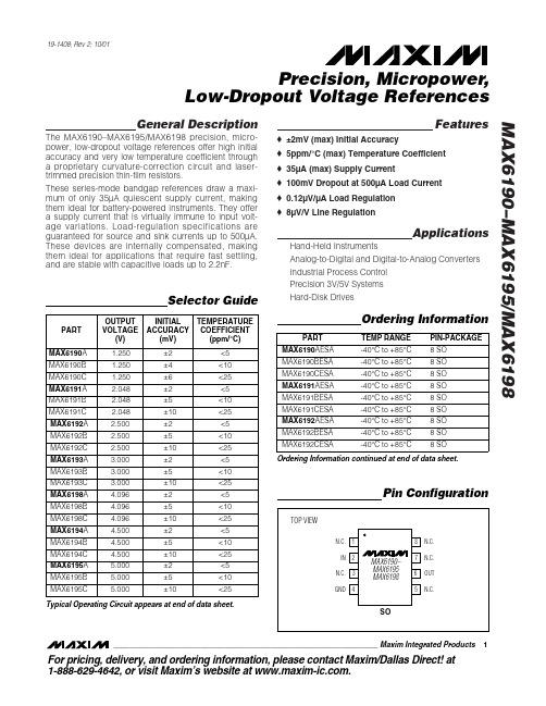
MAX6190– MAX6195 MAX6198
8 N.C. 7 N.C. 6 OUT 5 N.C.
SO
________________________________________________________________ Maxim Integrated Products 1
For pricing, delivery, and ordering information, please contact Maxim/Dallas Direct! at 1-888-629-4642, or visit Maxim’s website at .
80
µV/V
0.5 µV/µA
0.6 mA
ppm
ppm/ 1000hrs
µVP-P
µVRMS
dB
µs
2.2
nF
12.6
V
35
µA
2
µA/V
2 _______________________________________________________________________________________
Output-Voltage Temperature Coefficient (Note 1)
SYMBOL
CONDITIONS
VOUT TA = +25°C
TCVOUT
MAX6190A MAX6190B MAX6190C
MAX6190A MAX6190B MAX6190C
MIN
1.248 1.246 1.244
Selector Guide
PART
OUTPUT
INITIAL TEMPERATURE
测速雷达主要设备功能及技术参数

测速雷达主要设备功能及技术参数测速雷达型号:KTR-C3(品牌:KITOZER/开拓者)采用高速DSP信号处理芯片、0.1秒快速捕捉。
1)设计小巧轻便、制作精良。
2)纯铸铁结构,坚固耐用。
3)232串口输出。
4)精确度高,捕捉目标速度快。
5)动态时具有同向功能。
6)静态时可分别检测来车、去车。
7)静态测速范围:0~322 KPH。
8)移动测速范围:19~322KPH。
9)环境要求:温度:-30度 ~ +70度;湿度:0 % ~ 90% 。
10)Ka波段窄波雷达,微波频率:34.7GHz(Ka-band),可有效规避探测狗检测。
11)发射角:±4度。
12)规格:重:0.52kg、直径:6.7cm、长:11.8cm。
13)精确度:+/-1KPH。
高清摄像机(品牌:KITOZER/开拓者)高清摄像机功能:CCD成像,200万象素,主要端口有:闪光灯同步口,通过同步线与闪光灯连接;拍照触发口,当收到外部脉冲触发信号时,高清摄像机会抓取一张图片,脉冲信号由独立的拍照触发器发出;网口(100M),与控制主机连接,接收参数配置,上传图片,也可接收带由协议内容的抓拍命令。
产品详细参数表百万像素变焦镜头日本精工本次中煤平朔公司系统百万像素变焦镜头选型为日本精工SE5018MP产品,AVENIR ETOKU(日本精工)十几年来始终专心于监控镜头的市场发展,成为中国安防监控领域用得最多的专业镜头。
本次系统高清摄像机选型为广州莱安智能化系统开发有限公司出品的KTR200A型高清摄像机。
KTR200A是集成一体的高速彩色/单色智能工业相机,采用总像素200万像素的CCD图像传感器,具有处理速度快、分辨率高、图像质量好等特点。
广泛应用于智能交通、电子警察、卡口、高速公路、停车厂等领域的检测和识别。
百万像素网络拍照摄像一体机,将高清图像抓拍、标清视频摄像完美结合,超高清晰度,分辨率达130万~500万像素,专业用于如平安城市建设、机场、银行、道路卡口监控及牌照识别等安全防范领域,能够为客户提供专业的可定制产品及服务,支持后续增值开发。
飞龙 wi
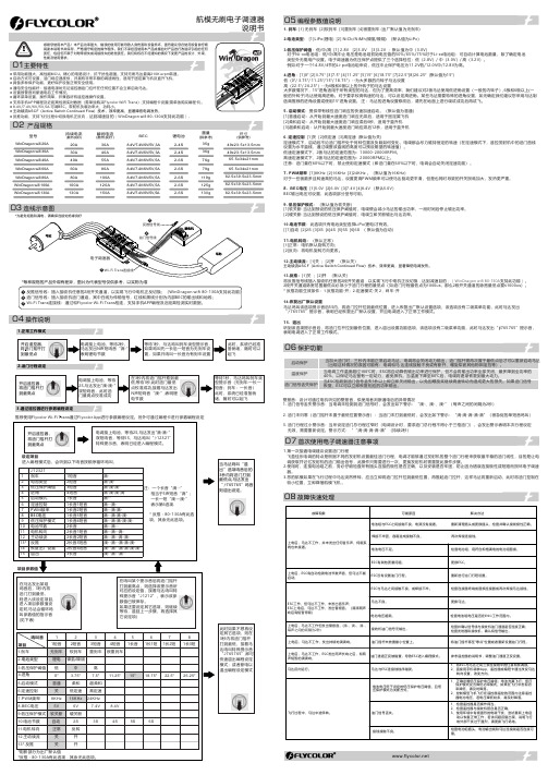
持续电流(散热良好)瞬间电流(散热良好)BEC尺寸(供参考)重量(供参考)20A 30A 40A 60A 30A 40A 55A 80A 锂电池型号79g 35g 36g 76g 49x23.5x13.5mm 65.5x34x21mm● 反推功能,支持飞行过程中切换电机正反向,达到减速目的(WinDragon wifi 80-130A 支持此功能)。
2-4S 2-4S 2-6S 2-6S 8.4V/7.4V/6V/5V ,5A 80A 100A 119g 2-6S 100A 120A 125g 2-6S 130A150A130g82.5x39.5x23.5mm2-6S航模无刷电子调速器WinDragon wifi 130AWinDragon wifi 100A WinDragon wifi 80A WinDragon wifi 60A WinDragon wifi 30A WinDragon wifi 40A WinDragon wifi 20A 8.4V/7.4V/6V/5V ,5A 8.4V/7.4V/6V/5V ,5A 8.4V/7.4V/6V/5V,5A8.4V/7.4V/6V/5V ,5A 82.5x39.5x23.5mm 82.5x39.5x23.5mm 65.5x34x21mm 49x23.5x13.5mm 02 产品规格04 操作说明1.正常工作模式2.油门行程设定3.通过遥控器进行参数编程设定推荐使用Flycolor Wi-Fi Trans 通过Flycolor App 进行参数编程设定。
另外可通过编程卡进行参数编程设定1. 刹车: [1] 无刹车 [2]软刹车 [3]重刹车 [4]很重刹车 (出厂默认值为无刹车)2.电池类型: [1]LiPo(锂电) [2] NiCb/NiMh(镍氢/镍隔) (默认值为Li Po )3.低压保护阈值:低/中/高 [1] 2.8V [2]3.0V [3]3.2V ;默认值为中(3.0V)对于Ni-xx电池组:低/中/高中止电压是电池组初始电压值的50%/65%/75%对于Li-xx电池组:可自动计算电池数量,除了确定电池 类型外无需用户设置。
F6系列中文使用说明书(all)

使用手册ATEQ F6th 系列F620 / F610 / F6701.04 版Reference: RF-28300D-UF6系列使用手册修订由于持续更新,本使用手册中包含的信息,本设备的功能和设计如有更改,将不另行通知。
前言/演示:定义、特点和测量原理(#673) 前面板和界面 (#676)安装/ 配件:气源 (#677)启动 (#678)配件 (#682)选配件 (#683)错误消息 (#684)以 CC/min显示结果 (#687)F610 电子连接器 (#692/1)F620 电子连接器(#692/2)F670 电子连接器(#692/7)气动连接器(#693)参数/ 特殊循环:特殊循环 (#623)服务特殊循环 (#631)程序选择 (#679)程序参数 (#680)测试循环管理 (#681)爆裂测试 (#698)程序功能:功能管理 (#601)名称 (#602)程序链接 (#603)单位 (#604)自动连接器 (#605)测试检查 (#606)ATR (#607)预充气模式和充气模式 (#608) 阀代码 & 24V辅助输出 (#609) 循环结束 (#610)迷你阀 (#611)复工界限 (#612)密封零件 (#613)N 测试 (#614)参考容积 (#615)标记 (#617)温度校正 1 (#618)峰值保持 (#620) 正负号 (#621)过滤 (#622)流量水平 (#624)非负 (#625)绝对值 (#626)显示模式 (#627) 不排气(#630)蜂鸣器 (#639)外部排气 (#655)ATF (#685)隔断 (#686)By pass (#691)配置菜单:日期 / 时间 (#635)语言 (#642)电子调压阀 (#645)调压阀控制 (#646)稳定调压阀 (#647)压力传感器自动归零 (#648)自动短归零 (#649)排气水平 (#651)RS232 (#652)安全性 (#653)I/O 配置 (#654)IN7 测试 (#656)智能键 (#688)压力单位 (#695)USB (#696)结果菜单 / USB 菜单:储存 (#638)阀服务 (#658)I/O服务 (#661)系统信息 (#665)重置参数 (#669)结果菜单 (#689)服务 / USB (#690)CAN 状态 (#697)# 601: 功能管理# 602: 名称# 603: 程序链接# 604: 单位# 605: 自动连接器# 606: 测试检查# 607: ATR# 608: 预充气模式和充气模式# 609: 阀代码 & 24V 辅助输出# 610: 循环结束# 611: 迷你阀# 612: 复工界限# 613: 密封零件# 614: N 测试# 615: 参考容积# 617: 标记# 618: 温度校准 1# 620: 峰值保持# 621: 符号取反# 622: 过滤# 623: 特殊循环# 624: 流量水平# 625: 非负# 626: 绝对值# 627: 显示模式# 631: 服务特殊循环# 635: 日期 / 时间# 638: 储存# 639 : 蜂鸣器# 642: 语言# 645: 电子调压阀# 646: 调压阀控制# 647: 稳定调压阀# 648: 压力传感器自动归零# 649: 自动短归零# 651: 排气水平# 652: RS232# 653: 安全性# 654: I/O 配置# 655 : 外部排气# 656: IN7 测试# 658: 阀服务# 661: I/O 服务# 665: 系统信息# 669: 重置参数# 673: 定义,特性和测试原理# 676: 前面板和界面# 677: 气源# 678: 启动# 679: 程序选择# 680: 程序参数 (Leak)# 681: 测试循环管理# 682: 配件# 683: 选配件# 684: 错误消息# 685: ATF# 686: 隔断# 687: 以CC/min显示结果# 688: 智能键# 689: 结果菜单# 690: 服务 / USB# 691: By pass# 692/1: F610电子连接器# 692/2: F620电子连接器# 692/7: F670 电子连接器# 693: 气动# 695: 压力单位# 696: USB# 697: CAN 状态# 698 : 爆裂测试功能管理扩展菜单功能能够进行个性化设置和添加个人选项到测试循环当中。
爱普生保护站无线电源61062说明书
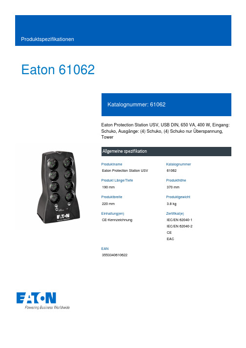
Eaton 61062Eaton Protection Station USV, USB DIN, 650 VA, 400 W, Eingang:Schuko, Ausgänge: (4) Schuko, (4) Schuko nur Überspannung,TowerAllgemeine spezifikationProduktname KatalognummerEaton Protection Station USV61062Produkt Länge/Tiefe Produkthöhe190 mm370 mmProduktbreite Produktgewicht220 mm 3.8 kgEinhaltung(en)Zertifikat(e)CE-Kennzeichnung IEC/EN 62040-1IEC/EN 62040-2CEEACEAN3553340610622400 W0,6TowerNeinSchutzkontakt (SCHUKO)161 V284 VEaton UPS Companion (ermöglicht eine sichere Systemabschaltung, Stromverbrauchsmessung und Konfiguration der USV-Einstellungen)Auswechselbarverschlossen, Bleisäurebatterie98Eaton Protection Station UPS - 650/800 VA - Installation and user manual (multiple languages)EU Declaration of Conformity Eaton Protection Station UPSLeistungAusg.leist.faktor FormfaktorBeinhaltet Netzwerkkarte Eingangsanschluss Eingangsspannung – min Ausgangsspannung – max Softwarekompatibilität Batteriewechsel BatterietypEffizienzBesondere Merkmale Benutzerhandbücher Zertifizierungsberichte3-in-1-Konzept: USV +Überspannungsschutz + Mehrfachsteckdosenleiste Enthält ein leistungsstarkes Überspannungsschutzgerät, das der Norm IEC 616431 entsprichtMit der EcoControl-Funktion sparen Sie bis zu 30 % mehr Strom als mit USVs der Vorgängergeneration8 Steckdosen zum Anschluss Ihres PCs undIhrer Peripheriegeräte oderIhrer AV-AusrüstungSchutz der Datenleitung, um sicherzustellen, dass die Internetleitung(einschließlich xDSL) vorÜberspannungen geschütztistUSB-Anschluss und Energieverwaltungssoftwarefür Windows/Linux/Mac als StandardBauformFreistehendes ModellAusgangsspannung – min161 VFarbeSchwarzErweiterte AkkukapazitätNoAusgangsspannungsbereich184–264 V (einstellbar auf 161–284 V)TopologieOfflineÜberspannungsschutzJaLaufzeit auf Halblast1 minEingangsnennspannung230 V Standard (220/230/240 V)Eingangsfrequenz-Bereich46-70 HzEingangsspannung – max284 VSpannungsartACPhase (Ausg.)1AkkumanagementWechselbare Batterien, automatischer Batterietest, Tiefentladeschutz, kaltstartfähigAutomatische AusschaltfunktionJaBetriebstemperatur - min0 °CVA Wert650 VAPotentialfreier SchaltkontaktNeinSteckdosen(4) Schuko, (4) Schuko, nur ÜberspannungPhase (Ein.)1VerpackungsinhaltBefestigtes NetzkabelUSB-KabelBenutzerhandbuch in 20SprachenSicherheitshinweise,Geräuschpegel< 25 dB bei 1 MeterEinspeisungstyp1LaufzeitgrafikAnzeige des LaufzeitgraphsBenutzeroberflächeLEDsAnzahl Batterien1Betriebstemperatur - max35 °CSpannung230 VEingangskabellänge1,5 mTemperaturbereich0° bis 35°C (32° bis 95°F)Ethernet-SchnittstelleNeinKommunikationUSB-Port (HID-konform), Kabel im Lieferumfang enthaltenRelative Luftfeuchtigkeit0-85 % ohne BetauungAusgangsscheinleistung650 VARack-Montage-BausatzNeinAnzahl der Ausgänge PC (SCHUKO)8Ausgangsfrequenz50/60 HzLaufzeit bei Volllast1 Min.SchnittstellentypUSBPrimäre Frequenz - min46 HzBatterieleistung12 V/7,2 AhTypUSV-AnlageAusgangsnennspannung230 V Standard (220/230/240 V)ErweiterungssteckplätzeNoEingangsspannungsbereich184–264 V (einstellbar auf 161–284 V)Nennfrequenz50/60 HzPrimäre Frequenz - max70 HzHöhe2000 mEaton Konzern plc Eaton-Haus30 Pembroke-Straße Dublin 4, Irland © 2023 Eaton. Alle Rechte vorbehalten. Eaton ist eine eingetrageneMarke.Alle anderen Warenzeichen sindEigentum ihrer jeweiligenBesitzer./socialmedia。
FAR-G6CH-1G8425-L222-T中文资料
FUJITSU MEDIA DEVICE DATA SHEET
DS04-23121-5E
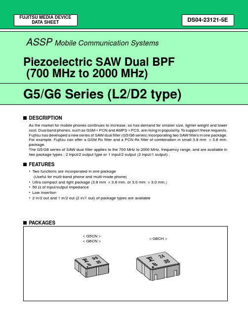
ASSP Mobile Communication Systems
Piezoelectric SAW Dual BPF (700 MHz to 2000 MHz)
G5/G6 Series (L2/D2 type)
Remarks
3.0 mm × 3.0 mm 3.0 mm × 3.0 mm 3.8 mm × 3.8 mm 3.8 mm × 3.8 mm 3.8 mm × 3.8 mm 3.8 mm × 3.8 mm 3.8 mm × 3.8 mm Low insertion loss type 3.8 mm × 3.8 mm High Aff. type 3.8 mm × 3.8 mm 3.8 mm × 3.8 mm 3.8 mm × 3.8 mm 3.0 mm × 3.0 mm 3.8 mm × 3.8 mm
4
元器件交易网
G5/G6 Series
s STANDARD DEVICES
No.
1
Part number
FAR-G5CN-942M50-D296
System
PDC800 Tx
Frequency (MHz)
893 MHz to 898 MHz 925 MHz to 960 MHz 810 MHz to 843 MHz 870 MHz to 885 MHz 824 MHz to 849 MHz 1850 MHz to 1910 MHz 869 MHz to 894 MHz 1930 MHz to 1990 MHz 890 MHz to 915 MHz 1710 MHz to 1785 MHz 935 MHz to 960 MHz 1805 MHz to 1880 MHz 925 MHz to 960 MHz
FLUKE六类永久链路测试报告参数详解
FLUKE六类永久链路测试报告参数详解flukedtx系列六类双绞线测试参数说明:1.插入损耗:是指发射机与接收机之间,插入电缆或元件产生的信号损耗,通常指衰减。
插入损耗以接收信号电平的对应分贝(db)来表示。
对于光纤来说插入损耗是指光纤中的光信号通过活动连接器之后,其输出光功率相对flukedtx系列六类双绞线测试参数说明:1.插入损耗:指在发射机和接收机之间插入电缆或元件引起的信号损耗,通常指衰减。
插入损耗用接收信号电平的相应分贝(DB)表示。
对于光纤,插入损耗是指光纤中的光信号通过可移动连接器后,输出光功率与输入光功率之比的分贝。
2.next(近端串扰):是指在与发送端处于同一边的接收端处所感应到的从发送线对感应过来的串扰信号。
在串扰信号过大时,接收器将无法判别信号是远端传送来的微弱信号还是串扰杂讯。
3.Psnext(集成近端串扰):它实际上是一个计算值,而不是直接测量结果。
Psnext是根据每对线对其他三对线的next影响通过公式计算得出的。
Psnext和FEXT(稍后介绍)是非常重要的参数,可以确保布线系统的性能能够支持同时传输四对导线(如千兆以太网)的应用。
4.ACR(衰减串扰比):指链路中的有效信噪比。
ACR只是衰减与下一个衰减的比率,它测量来自远端的衰减信号与串扰噪声之间的比率。
例如,一位讲师在老师面前讲课。
演讲者的目标是使受训者能清楚地听到他的演讲。
演讲者的音量是一个重要因素,但更重要的是,演讲者的音量与背景噪音之间的差异。
如果讲师在安静的图书馆里讲话,甚至可以听到耳语。
想象一下,如果同一位讲师在繁忙的足球场上以同样的音量讲话,会发生什么。
教练必须提高音量,使他的声音(要求的信号)与人群的欢呼声(背景噪音)完全不同,以至于可以听到。
这里是acr。
ACR=衰减信号-近端串扰产生的噪声5.psacr(综合衰减串扰比):反映了三对线同时进行信号传输时对另一对线所造成的综合影响。
它只要用于保证布线系统的高速数据传输,即多线对传输协议。
xc6192系列电池供电设备电源按钮开关芯片数据手册说明书
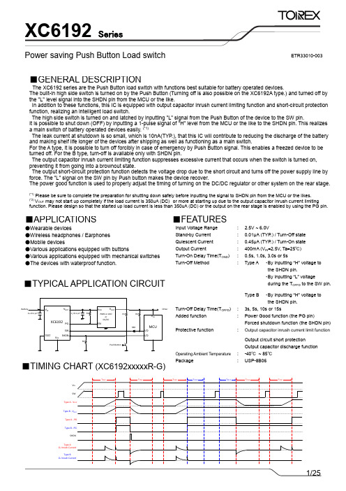
XC6192SeriesPower saving Push Button Load switch ETR33010-003■BLOCK DIAGRAMXC6192AXC6192B* Diodes inside the circuit are an ESD protection diodes and a parasitic diodes.OUTSSV IN SWSHDNOUTSSV IN SWSHDNXC6192Series ■PRODUCT CLASSIFICATION●Ordering Information(*1)●Selection GuideParts No. Turn-On Delay Time (s) Turn-Off Delay Time (s) PackageXC6192AA05ER-G0.5s 5sUSP-8B06XC6192AA10ER-G 10sXC6192BANNER-G Not applicable■PIN CONFIGURATION*The dissipation pad for the USP-8B06 package should be solder-plated in recommended mount pattern and metal masking so as to enhance mounting strength and heat release.When taking out a potential of the heat-sink, connect with V SS pin (#5 pin).■PIN ASSIGNMENTPIN NUMBER PIN NAMEFUNCTIONUSP-8B061 V IN Power Supply Input2 N.C No connection pin(The N.C pin should be connected the V SS pin.) 3 SW Push Button Signal input pin 4 PG Power Good Status Output 5 V SS Ground Pin6 TEST The TEST pin must be connected the V SS pin.7 SHDNForced Shutdown pin 8V OUTOutput pin■PIN FUNCTIOS ASSIGNMENTPIN NAME SIGNALSTATUS SW (*3)L ActiveH Keep the current state OPEN Undefined State (*1) SHDN (*3)LKeep the current state H Shut down OPEN Undefined State (*1) PGLow impedance V OUT < V RUSH (*2) High impedanceV OUT ≥ V RUSH (*2)(*1) Please do not leave the SW pin and the SHDN pin open. Each should have a certain voltage (*2) Please refer to electrical characteristics.(*3)Please refer to notes on use.43215867V OUT SHDN TEST V SS V IN N.C SW PGUSP-8B06(BOTTOM VIEW)XC6192Series ■ABSOLUTE MAXIMUM RATINGSXC6192Series■TEST CIRCUITSTest Circuit (1)Unless otherwise stated, V SS common, V IN =6.0V, V SW =6.0V, V SHDN =0V, V PG =Open, I OUT =0mA, C IN =0.1μF, C L =0.1μF■TYPICAL APPLICATION CIRCUIT【Typical Examples】(*1) Please select freely according to the threshold of the MCU's I/O.XC6192Series■OPERATIONAL EXPLANATIONThe XC6192 series A type fixes V OUT at “H” voltage (same level as the V IN pin voltage) when “L” voltage is input the required time into the SW pin, and shuts down V OUT (same level as GND) when “L” voltage is subsequently input the required time into the SW pin, thereby realizing alternating ON/OFF control (*1). Two shutdown methods are available: inputting “H” voltage into the SHDN pin, and inputting “L” voltage the required time into the SW pin.(*1)Alternating ON/OFF control on this IC is a system that alternates between VOUT “H” voltage and shutdown each time “L” voltage is input the required time into the SW pin.The B type fixes V OUT at “H” voltage when “L” voltage is input the required time into the SW pin. After V OUT is fixed at “H” voltage, the signal is not accepted if “L” voltage is subsequently input into the SW pin. The shutdown method is inputting “H” voltage into the SHDN pin.As protective functions, the XC6192 series is equipped with a rush current prevention circuit and a short-circuit protection circuit.OUTV IN SWSHDN■OPERATIONAL EXPLANATION (Continued)[Turn-On sequence: Fig.3]On the XC6192 series, when “L” voltage is input for the duration T OND into the SW pin with V OUT fixed at “L” voltage, the Pch pre-driver transistor PM1 (Fig.1) turns ON and V OUT starts to rise. If the SW pin is switched from “L” voltage to “H” voltage while V OUT is rising by PM1, V OUT will change to the shutdown state.When the V OUT pin voltage reaches Inrush Current Limit Voltage (V RUSH: refer to Electrical Characteristics), the main driver transistor PM2 (Fig.1) turns ON, and V OUT is fixed at “H” voltage even if the SW pin voltage changes to “H” voltage.When the V OUT pin voltage reaches V RUSH, the Nch transistor NM1 that is connected to the PG pin (Fig.1) turns OFF and the PG pin changes to high impedance.These operations suppress rush current to the capacitor that is connected to the V OUT pin and allow the input power supply to maintain stability. In addition, by connecting the PG pin to the Enable pin of the device that follows the XC6192 series, malfunctioning of that device is prevented. (Fig.2)[Shutdown sequence: Fig.4]On the XC6192 series, when one pulse of “H” voltage (at least 1ms as a guideline) is input into the SDHN pin with V OUT fixed at “H” voltage, V OUT changes to the shutdown state and the IC enters the standby state.[Turn-Off sequence: Fig.5]On the A type, when “L” voltage is input into the SW pin for the duration T OFFD with V OUT fixed at “H” voltage, V OUT shuts down. After shutdown, returning the SW pin to “H” voltage reduces the supply current to the standby current while holding the IC’s logic.The B type does not have this function.V OUT Pin VoltagePG Pin VoltageSHDN pin Voltage[Operation after Turn-On: Fig. 6]On the A type, when “L” voltage is input into the SW pin for the duration T OND and V OUT is fixed at “H” voltage, and then “L”voltage is input into the SW pin for the duration T OFFD , the Turn-Off sequence cannot be initiated. To initiate the Turn-Off sequence, “H” voltage must be input into the SW pin, and then “L” voltage must again be input for the duration T OFFD . The B type does not have a Turn-Off sequence by SW pin.[Operation after Turn-Off:Fig.7]On the A type, when “L” voltage is input into the SW pin for the duration T OFFD and V OUT is shut down, and then “L” voltage isinput into the SW pin for the duration T OND , the Turn-On sequence cannot be initiated.To initiate the Turn-On sequence, “H” voltage must be input into the SW pin, and then “L” voltage must again be input for the duration T OND .The B type does not have a Turn-Off sequence by SW pin.[Operation after shutdown: Fig. 8]On the XC6192 series, in order to initiate the Turn-On sequence after “H” voltage is input into the SHDN pin and V OUT is shut down, “H” voltage must be input into the SW pin and then “L” voltage must again be input for the duration T OND.[Inrush current limit and output short circuit protection:Fig.9 ]The XC6192 series has a function that limits rush current and a circuit that shuts down the output when an output short-circuit is detected.During the time until the V OUT pin voltage reaches V RUSH during the Turn-On sequence, only PM1 turns ON, and therefore the voltage rises through the Pre-driver On Resistor (R ONP: refer to the Electrical Characteristics).When the V OUT pin voltage reaches V RUSH or more, PM2 turns ON and rush current limiting is released.The rush current at the instant when PM1 turns ON is calculated using the following equation.Inrush Current = V IN / R ONP (A)In addition, during the time until the V OUT pin voltage reaches V RUSH by means of the rush current limiting function, the load current while V OUT rises must be set to less than the value given by the equation below.Start-up Load Current < (V IN – V RUSH (Max.)) / R ONP (A)Example: 4.2V – 4.15V / 135 Ohms = 0.359mA;Note this very low 0.359mA is used to charge the output capacitors. If startup load current exceeds this, the output current will pass thru PM1 only, and have a 135 ohm resistor creating a voltage drop. If it’s noticed that V OUT is significantly below V IN, please ensure start-up load current is NOT exceeded.If the V OUT pin voltage drops below the Short Circuit Detect Voltage (V SHORT: refer to the Electrical Characteristics) after the Turn-On sequence, a short-circuit is detected and PM1 and PM2 are latched in the OFF state, causing V OUT to shut down. The relation between the output current (I SHORT) and V SHORT when a short circuit occurs is given by the equation below.I SHORT = (V IN - V SHORT) / R ON (A)The equation for the maximum output current is as follows.I OUT (Min.) = (V IN - V SHORT (Max.)) / R ON (Max.) (A)[SW pin]When “L” voltage is input into the SW pin for the duration T OND with the IC in the standby state, the pin fixes V OUT at “H” voltage.On the A type, when V OUT is fixed at “H” voltage, “L” voltage can be input for the duration T OFFD to shut down V OUT.[SHDN pin]This pin shuts down V OUT when one pulse of “H” voltage (1ms or more as a guideline) is input into the SHDN pin with V OUT fixed at “H” voltage.[PG pin]NM1 and R2 (Fig.1) are connected to the PG pin.NM1 is an Nch MOSFET and is synchronized with the GATE signal of PM2, so NM1 turns OFF when PM2 turns ON.[VOUT pin]PM1, PM2, and R1 (Fig.1), and R2 (Fig.1) and the CL discharge transistor NM2 (Fig.1) are connected to the output pin.PM1 is a Pch MOSFET, and is effective in preventing rush current.PM2 is a Pch MOSFET and functions as the main driver.NM2 is an Nch MOSFET, and is synchronized with the GATE signal of PM1. Therefore, when PM1 turns ON, NM2 turns OFF.[SW Circuit]This circuit transmits the signal input into the SW pin to the internal circuitry.[SHDN Circuit]This circuit transmits the signal input into the SHDN pin to the internal circuitry.[VREF & POR]This circuit supplies the internal circuit reference voltage and is a reset circuit that is input into the logic circuitry.[Type Select]This circuit selects the product type.[Turn-On Delay Counter]This circuit count-controls the time until V OUT is fixed at “H” voltage after “L” voltage is input into the SW pin.During the time until the count is completed, the counter circuit can be returned to the initial state by inputting “H” voltage into the SW pin.[Turn-Off Delay Counter]This circuit only operates on the A type.When V OUT is fixed at “H” voltage, this circuit count-controls the time from input of “L” voltage into the SW pin until V OUT shuts downDuring the time until the count is completed, the counter circuit can be returned to the initial state by inputting “H” voltage into the SW pin.[VREF2 & POR2]This circuit sets the initial state of the V OUT pin.The circuit is set so that V OUT is in the shutdown state when the power is turned on, so there is no need to input “H” voltage into the SHDN pin after power is supply to shut down the output.[Inrush Current Limit]This circuit limits rush current until the V OUT pin voltage reaches V RUSH.[Short Circuit Protect]This circuit outputs a shutdown signal if the V OUT pin voltage reaches V SHORT.[Gate Slope]After the V OUT pin voltage reaches V RUSH, this circuit gradually changes the GATE voltage of PM2 from “H” voltage to “L” voltage.■NOTES ON USE1) For temporary, transitional voltage drop or voltage rising phenomenon. The IC is liable to malfunction should the ratings beexceeded.2) Please use this IC within the specified operating ranges.3) In some cases, power supply noise may cause malfunctioning of the internal counter circuit. Sufficiently reinforce the V IN,V OUT, and GND lines, and connect 0.1μF or higher capacitors near the IC between V IN and GND (V SS), and between V OUT and GND (V SS).4) Turn-On Delay Time characteristics and Turn-Off Delay Time characteristics are increased when using a capacitor largerthan 0.1 μF for CL connected to V OUT - GND (V SS). Sufficiently test actual operation before use.5) When “L” level is input into the SW pin, Operation Current flows. Sufficiently test actual operation before designingperipheral circuits.6) The SW pin and SHDN pin are connected to the gate of a CMOS inverter. If a voltage lower than the V IN pin voltage or avoltage higher than the V SS pin voltage is input into each pin, the flow-through current of the CMOS inverter may appear as supply current.7) If an intermediate voltage between “L” voltage and “H” voltage is input into the SW pin or SHDN pin, starting and stoppingof the IC may become unstable. Sufficiently test peripheral components and other parts to ensure that an intermediate voltage between “L” voltage and “H” voltage is not continuously input for an excessive time into the SW pin and SHDN pin.8) The TEST pin must be connected to GND (V SS).9) When using for an application other than a push-button application, please design the timing to include deviations and testsufficiently with the actual device before use.10) The USP-8B06 is a thin surface-mount package. Therefore, distortion of the board during PCB mounting may betransmitted to the IC chip, which may affect Turn-On Delay Time characteristics and Turn-Off Delay Time characteristics.Sufficiently test actual operation before use.11) Torex places an importance on improving our products and their reliability.We request that users incorporate fail-safe designs and post-aging protection treatment when using Torex products in their systems.(12) SHDN pin "H" "L" Voltage vs. Ambient Temperature(13) PG pin Output Current vs. Ambient Temperature(14) C L Discharge Current vs. Ambient Temperature0.500.550.600.650.700.750.800.850.90-50-25255075100125S H D N p i n "H " "L " V o l t a g e :V S H D N [V ]Ambient Temperature :Ta [℃]X C6192SeriesVSHDN "H" Voltage VSHDN "L" VoltageV IN =2.5VC IN =0.1uF, C L =0.1uF0.500.550.600.650.700.750.800.850.90-50-25255075100125S H D N p i n "H " "L " V o l t a g e :V S H D N [V ]Ambient Temperature :Ta [℃]X C6192SeriesVSHDN "H" Voltage VSHDN "L" VoltageV IN =3.7VC IN =0.1uF, C L =0.1uF0.500.550.600.650.700.750.800.850.90-50-25255075100125S H D N p i n "H " "L " V o l t a g e :V S H D N [V ]Ambient Temperature :Ta [℃]X C6192SeriesVSHDN "H" Voltage VSHDN "H" VoltageV IN =6.0VC IN =0.1uF, C L =0.1uF1.501.601.701.801.902.002.102.20-50-25255075100125P G p i n O u t p u t C u r r e n t :I P G [m A ]Ambient Temperature :Ta [℃]X C6192SeriesTurn-Off State, V IN =2.5V, V PG =0.3V C IN =0.1uF, C L =0.1uF1.501.601.701.801.902.002.102.20-50-25255075100125C LD i s c h a r g e C u r r e n t :I D C G [m A ]Ambient Temperature :Ta [℃]X C6192SeriesTurn-Off State, V IN =2.5V, V OUT =0.3V C IN =0.1uF, C L =0.1uF■PACKAGING INFORMATIONFor the latest package information go to, /technical-support/packagesPACKAGE OUTLINE / LAND PATTERN THERMAL CHARACTERISTICSUSP-8B06 USP-8B06 PKG High heatdissipation Board USP-8B06 Power Dissipation■MARKING RULE① represents product series.MARK PRODUCT SERIE 2 XC6192******-G② represents Type and Turn-On delay time. MARK Type Turn-On delay time PRODUCT SERIE0 A0.5s XC6192AA****-G 1 1.0sXC6192A1****-G 2 3.0s XC6192A3****-G 3 5.0s XC6192A5****-G 4 B0.5s XC6192BA****-G 5 1.0sXC6192B1****-G 6 3.0s XC6192B3****-G 7 5.0sXC6192B5****-G③ represents Turn-Off delay time.MARK Turn-Off delay timePRODUCT SERIE A 3s XC6192**03**-G B 5s XC6192**05**-G C 10s XC6192**10**-G D 15s XC6192**15**-G 0-XC6192B*NN**-G④,⑤ represents production lot number01~09, 0A~0Z, 11~9Z, A1~A9, AA~AZ, B1~ZZ in order. (G, I, J, O, Q, W excluded) * No character inversion used.。
中英文安装说明书20111年_FCC_

Enclosure Climate Control Unit工业控制柜制冷机Assembly Instructions安装说明书(FCC系列)雷子克(广州)电气设备有限公司 Let Us Take You To The Top...3.3顶装按照开孔图开孔, 再锁紧制冷机底部内置的螺丝孔保证制冷机与控制柜的固定与密封。
4.安全与注意安全提示¾制冷机为精密电气,搬运务必轻放,严禁倒置,倾斜存放。
¾安装制冷机前,应该先取开外壳,(松开制冷机顶部的螺丝,由下向上垂直推卸外壳),把制冷机安装上控制柜后再把外壳装上制冷机(靠紧制冷机四周边框,由上向下卡入钩环,再拧紧制冷机顶部的两粒螺钉)¾因制冷机为无冷凝水设计,制冷机的出水管只为安全备份使用,正常使用时无水导出,不必考虑冷凝水的处理。
注意事项¾制冷机在灰尘大,或油性,毛绒的环境务必及时清理过滤网,否则会影响制冷机性能。
¾制冷机入风口需安装到控制柜体的上部。
¾控制柜外的温度不能超过55摄氏度,但短暂的高温并不影响制冷机运作。
¾包装应完好,如果发现制冷机有油渍,极有可能是泄漏制冷剂,包装的任何损坏都有可能引起制冷机的故障。
¾控制柜必须达到IP54,如果控制柜有漏洞或缝隙,冷凝水可能会发生。
¾制冷机之间或制冷机与墙壁距离至少不小于200mm¾在控制柜内部,制冷机入风和出风口不可有障碍物阻塞。
¾制冷机需水平安装、使用,最大倾斜角度不大于2°¾维护及送电必须由专业人员操作。
¾为避免冷凝物的形成,建议采用门位开关,保证当控制柜门打开时,制冷机必须关闭。
¾控制柜内部的电气元件的热释放不能超过制冷机可用制冷功率,否则会出现制冷机长期运作。
¾不可用任何方式修改制冷机。
5.电气联接电压与频率必须与制冷机的铭牌相匹配,在制冷机电气联接前端不可有其他的温度控制,制冷机上回路电保护元件应与制冷机额定功率相吻合,在安装时参考相关说明。
Ruffneck FX6系列爆炸防护电气空气加热器产品说明书
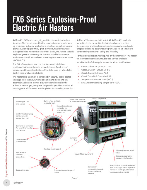
Arctic Duty MotorSpare fuse locatedin convenient holderJunctionboxFigure 16Ruffneck™Notes* Exceeds the 48 amp circuit limit of NEC 424-22. DS not available for these units.**480 V: 1-phase units are certified for Class I, Div. 1, Group D and Class II, Div.1 Groups F & G1. Minimum conductor size for 86˚F (30˚C) ambient. Derate conductor forambient temperature. Use minimum 194˚F (90˚C) insulation.2. Heater is functioning normally if at rated voltage the amp draw iswithin 10% of the value in this table.3. Operation at lower voltages will result in reduced heat output and ampdraw.4. Add “T” to model number when adding a built-in thermostat.5. Add “D” to model number when adding a built-in disconnect switch.6. Add “P” to model number when adding a built-in pilot light.7. Add “U” to model number for units with continuous fan option.8. Add “A” to model number for units with stainless steel cabinet.9. Add “L” for large junction box.10. Add "C" to model number for units with Heresite coating.For installation and model coding, see page C10.Consult Terms & Conditions of Sale or FX6 Owner’s Manual for warranty information.7Ruffneck™8Ruffneck™E x p l o s i o n -P r o o f E l e c t r i c A i r H e a t e r s –F X 6 S e r i e sInstallation Conditions࢞The FX6 Series Electric Air Heaters are for dry indoor use only. Donot immerse in water. Do not store or use in areas exposed to rain or snow.࢞The FX6 heaters are to be used only in atmospheres having anignition temperature higher than 329°F (165°C).࢞Altitude restrictions apply, see General Specifications, page 11࢞Heaters should be connected to a fixed power supply and mustbe permanently mounted in a level, upright position during operation.࢞Read and be aware of the terms of our Warranty located in theowner’s manual.࢞For more information please refer to owner's manual.* Exceeds the 48 amp circuit limit of NEC 424-22. DS not available for these units.**480 V: 1-phase units are certified for Class I, Div. 1, Group D and Class II, Div. 1 Groups F & G 1. Minimum conductor size for 86˚F (30˚C) ambient. Derate conductor for ambient temperature. Use minimum 194˚F (90˚C) insulation.2. Heater is functioning normally if at rated voltage the amp draw is within 10% of the value in this table.3.Operation at lower voltages will result in reduced heat output and amp draw.4. Add “T” to model number when adding a built-in thermostat.5. Add “D” to model number when adding a built-in disconnect switch.6. Add “P” to model number when adding a built-in pilot light.7. Add “U” to model number for units with continuous fan option.8. Add “A” to model number for units with stainless steel cabinet.9.Add “L” for large junction box.10. Add "C" to model number for units with Heresite coating.ote: N*For specifications common to all FX6 models, see General Specifications, page 11. Weights are an approximate maximum. Manufacturer reserves the right to replace motors with suitable alternates.9 Ruffneck™elEfoorP-noisolpxE10Ruffneck™11Ruffneck™ FX6 Series – Explosion-Proof Electric Air HeatersGeneral Specifications1. Hazardous Location RatingClass I, Divisions 1 and 2; Groups C and D; Class II, Groups E, F and G;Class II Division 2, Groups F & G; Class I Zones 1 & 2, Groups IIA & IIBTemperature Code T3B [329°F (165°C)]*2. Enclosures NEMA Type 7 & 9. For dry, indoor use only. Do not immerse in water. Do not store or use in areas exposed to rain or snow3. Motor Type Explosion-proof. Thermally protected. Permanently lubricated ball bearings.4. Fan Aluminum blade. Steel spider and hub with 5/8" (15.875 mm) bore5. Fan Guard Split design with close wire spacing. 1/4" (6.3 mm) diameter probe will not enter 6. Mounting Holes Two 9/16". (14.3 mm) diameter holes at top7. Heating Elements Three long-life, low watt-density, high grade metal sheathed elements 8. Temperature High-Limit Automatic reset type, snap-action bimetal, open on temperature rise. Rated 100,000 cycles at 10 amps, handles 0.128 amps 9. Control Circuit 120 V, 0.128 amps, 15 VA. (Grounded)10. Safety Protection Circuit Snap action bimetal switch, rated for 100,000 cycles at 10 amps. Part of secondary thermal protection circuit with dedicated contactor. Independent of main control circuit.11. Slim Junction Box 10.25" (230 mm) x 8.00" (180 mm) x 6.75" (172 mm) 12. Optional Built-in Thermostat Explosion-proof. 36°F to 82°F (2°C to 28°C)13. Optional Built-in Disconnect Switch DS for use only on heaters with total current not exceeding 48 amps. Lockout handle accepts 1/4" diameter padlock shackle 14. Optional Pilot Light Indicates heat-on cycle15. Control TransformerMulti-tap primary, 120 V secondary, 50 VA16. Contactors75 amps. Rated for 1,000,000 mechanical operations. 120 V, 15 VA coil (separately fuse-protected)17. Heat Transfer Fluid Proprietary heat transfer fluid18. Cabinet Material 12 ga. (0.104") (2.60 mm) steel. Epoxy coated with five-stage pretreatment, including iron phosphate. Optional stainless steel.19. CoreSteel with integral aluminum fins, vacuum charged and hermetically sealed 20. C onduit Material Heavy walled, 0.122" (3.1 mm) steel21. Overpressure Protection Preset 100 psig (690 kPa) pressure relief valve, no field serviceable parts. Preset 300 PSIG (2070 KPa) rupture disk, no field servicable parts.22. O perational Temperature Limitations -58ºF to 104ºF (-50ºC to 40ºC)23. S torage Limitations-58°F to 176°F (-50°C to 80°C). Do not immerse in water. Do not expose to rain or snow.THS2053-0922。
卡莱恩科技611 621系列小型杆状开关产品介绍说明书

The 611/621-Series small-size, sleek styling, actuator andtermination choices make this switch a cost effectivemost any switching need. Internationalapprovals, single or double pole circuitry, and ratings to Typical ApplicationsAppliances∙Audio-Visual∙Power Supplies2.YX.093[2.36]-.156[3.96].508[12.90].060[1.52]-.093[2.36].508[12.90].030[.762]-.060[1.52].508[12.90]PANEL THICKNESS.780[19.81].764[19.40].756[19.20].825.500PADDLENotes:1 Base part number specifies black rocker with black bezel. To specify paddle actuator change 2nd digit from 2 to 1. ex.: 61115919 = black paddle with black bezel. For additional ratings & colors, consult factory.2 Dry circuit rating is available, consult factory.3 Not available with 6(4) A 250 V rating or VDE approval.4 6(4)A 250V VDE approved rating available with On-none-Off and On-none-On circuits only.5 Available with visi-rocker option only.6 Consult factory for PC footprint.7 Rated 2A 250VAC, 5A 125 VAC resistive. ( ) Indicates momentary function.Ordering SchemeV W Configure Complete Part Number > Browse Standard Parts >Dimensional Specsinches [millimeters]SamplePart Number 62116919-0-9-VSelection1234Tech SpecsDielectric StrengthUL/CSA: 1000V - live to dead metal parts & opposite polarityVDE: 4000V - live to dead metal parts; 1250V opposite polarity & across open contactsElectrical Life50,000 cycles- single pole 50,000 cycles- double poleOperating Temperature32°F to 185°F (0°C to 85°C)*Manufacturer reserves the right to change product specification without prior notice.3.Authorized Sales Representatives and DistributorsAbout CarlingFounded in 1920, Carling Technologies is a leading manufacturer of electrical and electronic switches and assemblies, circuit breakers, electronic controls, power distribution units, and multiplexed power distribution systems. With six ISO9001 and IATF16949 registered manufacturing facilities and technical sales offices worldwide, Carling Technologies Sales, Service and Engineering teams do much more thanmanufacture electrical components, they engineer powerful solutions! To learn more about Carling please visit /company-profile .To view all of Carling’s environmental, quality, health & safety certifications please visit /environmental-certifications .Click on a region of the map below to find your local representatives and distributors or visit /findarep.© Carling Technologies, Inc.Carling, Visi-Rocker are registered trademarks of Carling Technologies, Inc. in the U.S. and other countries.。
FL6000 用户手册说明书
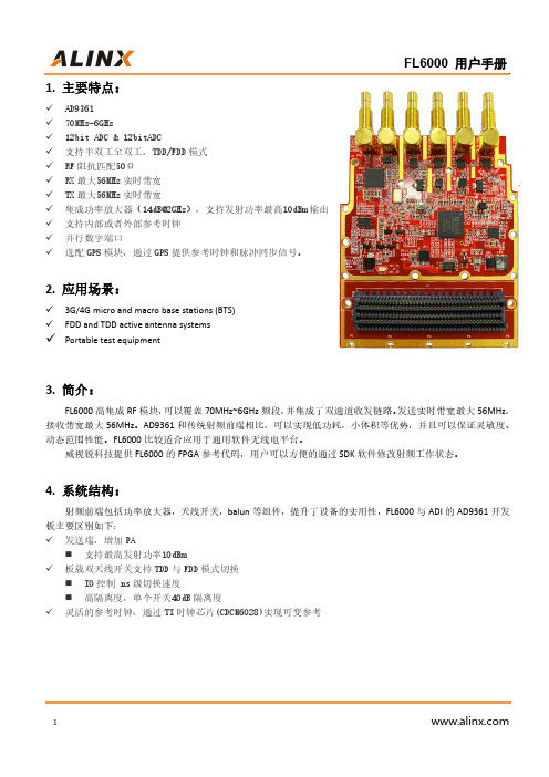
1.主要特点:✓AD9361✓70MHz-6GHz✓12bit ADC&12bitADC✓支持半双工全双工,TDD/FDD模式✓RF阻抗匹配50Ω✓RX最大56MHz实时带宽✓TX最大56MHz实时带宽✓集成功率放大器(14dB@2GHz),支持发射功率最高10dBm输出✓支持内部或者外部参考时钟✓并行数字端口✓选配GPS模块,通过GPS提供参考时钟和脉冲同步信号。
2.应用场景:✓3G/4G micro and macro base stations(BTS)✓FDD and TDD active antenna systems✓Portable test equipment3.简介:FL6000高集成RF模块,可以覆盖70MHz~6GHz频段,并集成了双通道收发链路。
发送实时带宽最大56MHz,接收带宽最大56MHz。
AD9361和传统射频前端相比,可以实现低功耗,小体积等优势,并且可以保证灵敏度、动态范围性能。
FL6000比较适合应用于通用软件无线电平台。
威视锐科技提供FL6000的FPGA参考代码,用户可以方便的通过SDK软件修改射频工作状态。
4.系统结构:射频前端包括功率放大器,天线开关,balun等组件,提升了设备的实用性,FL6000与ADI的AD9361开发板主要区别如下:✓发送端,增加PA⏹支持最高发射功率10dBm✓板载双天线开关支持TDD与FDD模式切换⏹IO控制ns级切换速度⏹高隔离度,单个开关40dB隔离度✓灵活的参考时钟,通过TI时钟芯片(CDCM6028)实现可变参考图1整体框图图2收发切换射频开关名称10TRX-SW TX->TRX TRX->MUX2FDD-TDD-SWRX<-RXMUX1->RX名称10REF_SELREFINGPS module5.射频指标:表1射频指标No.Items Specifications RemarkTx 1Frequency70~6000MHz2Interface SMB3Bandwidth Up to56MHz Tx real-time bandwidth,tunable 4Transmission Power10dBm2500MHz,CW5EVM<2%6Gain Control Range89dB7Gain Step0.25dB8ACLR<-45dBc@10dBm output9Spurious TBD10SSB Suppression35dBc11LO Suppression45dBc12DAC Sample Rate(max)61.44MS/s13DAC Resolution12bitsRx 1Frequency70~6000MHz2Interface SMB3Bandwidth Up to56MHz real-time bandwidth,tunable 4Sensitivity:-90dBm@20MHz5EVM<1.5%6Gain Control Range>60dB7Gain Step1dB8Noise Figure<6dB Maximum RX gain9IIP3(@typ NF)-15dBm10ADC Sample Rate(max)61.44MS/s11ADC Resolution12bits1Voltage 3.3V&12V2ON/OFF TIME<6uS TDD model3Duplexing Model TDD/FDD4Power Consumptions<3W6管脚列表:表2管脚列表信号名称FMC管脚名称FMC管脚方向备注AD9361芯片信号CLOCKOUT LA20_N G22输出可配置时钟输出CTRL_IN0LA26_P D26输出可配置控制信号CTRL_IN1LA22_N G25输出可配置控制信号CTRL_IN2LA21_P H25输出可配置控制信号CTRL_IN3LA25_P G27输出可配置控制信号CTRL_OUT0LA25_N G28输入可配置控制信号CTRL_OUT1LA24_N H29输入可配置控制信号CTRL_OUT2LA21_N H26输入可配置控制信号CTRL_OUT3LA22_P G24输入可配置控制信号CTRL_OUT4LA23_N D24输入可配置控制信号CTRL_OUT5LA24_P H28输入可配置控制信号CTRL_OUT6LA26_N D27输入可配置控制信号CTRL_OUT7LA16_N G19输入可配置控制信号EN_AGC LA16_P G18输入AGC使能控制ENABLE LA19_N H23输入TDD切换控制RESETB LA23_P D23输入低电平复位TXNRX LA17_N_CC D21输入TDD切换控制SPI_CLK LA18_N_CC C23输入SPI总线时钟SPI_CS#LA19_P H22输入SPI总线片选SPI_MISO LA20_P G21输入SPI总线数据SPI_MOSI LA18_P_CC C22输出SPI总线数据SYNC_IN LA17_P_CC D20输入同步触发信号RX_CLK_N CLK0_M2C_N H5输出LVDS数据时钟RX_CLK_P CLK0_M2C_P H4输出LVDS数据时钟RX_FRAME_N LA06_N C11输出LVDS数据帧同步RX_FRAME_P LA06_P C10输出LVDS数据帧同步RXD_N0LA08_N G13输出LVDS数据RXD_N1LA10_N C15输出LVDS数据RXD_N2LA04_N H11输出LVDS数据RXD_N3LA03_N G10输出LVDS数据RXD_N4LA05_N D12输出LVDS数据RXD_N5LA02_N H8输出LVDS数据RXD_P0LA08_P G12输出LVDS数据RXD_P1LA10_P C14输出LVDS数据RXD_P2LA04_P H10输出LVDS数据RXD_P3LA03_P G9输出LVDS数据RXD_P4LA05_P D11输出LVDS数据RXD_P5LA02_P H7输出LVDS数据FB_CLK_N CLK1_M2C_N G3输入LVDS数据回环时钟FB_CLK_P CLK1_M2C_P G2输入LVDS数据回环时钟TX_FRAME_N LA07_N H14输入LVDS数据帧同步TX_FRAME_P LA07_P H13输入LVDS数据帧同步TXD_N0LA12_N G16输入LVDS数据TXD_N1LA11_N H17输入LVDS数据TXD_N2LA13_N D18输入LVDS数据TXD_N3LA14_N C19输入LVDS数据TXD_N4LA15_N H20输入LVDS数据TXD_N5LA09_N D15输入LVDS数据TXD_P0LA12_P G15输入LVDS数据TXD_P1LA11_P H16输入LVDS数据TXD_P2LA13_P D17输入LVDS数据TXD_P3LA14_P C18输入LVDS数据TXD_P4LA15_P H19输入LVDS数据TXD_P5LA09_P D14输入LVDS数据FL6000附加信号CDCM_SPI_CLK LA29_N G31输入CDCM6208SPI配置总线CDCM_SPI_CS LA30_P H34输入CDCM6208SPI配置总线CDCM_SPI_MISO LA31_N G34输入CDCM6208SPI配置总线CDCM_SPI_MOSI LA30_N H35输出CDCM6208SPI配置总线CDCM_SYNC LA33_P G36输入CDCM6208同步触发GPIO_SCL SCL C30双向I2C eeprom AT24CM01GPIO_SDA SDA C31双向I2C eeprom AT24CM01PPS_1SR LA32_N H38输出GPS模块的1ppsREF_SELECT LA29_P G30输入1=外参考,0=内部GPS模块参考REF_SELECT2LA31_P G33输入0=内部VCTCXO晶振,1=外参考或GPS FDDTDD_SW LA28_N H32输入射频开关双工切换TRX_SW LA27_N C27输入射频开关双工切换TXD_GPSR LA32_P H37输出GPS模块UARTRXD_GPSR LA33_N G37输入GPS模块UART所有单端信号电平范围1.8V~2.5V7.FMC供电:扩展模块需要三种电源供电:12V:1A3.3V:1AVADJ:1A1.8V~2.5V8.FL6000尺寸图:图4FMC子板图9.FL6000实物图:图5实物图片10.FL6000典型指标测试:表3P1dB 输出功率频点(MHz)衰减值(mdB)txatt输出功率(dBm)5008e313.110008e312.615006e312.120005e312.925005e31230004e3 6.835002e37.540002e310.445002e310.250002e39.455002e3 6.358002e34.7表4接收5dB增益P1dB输入功率频点(MHz)P1dB输入(dBm) 500-10.81000-11.21500-12.12000-11.82500-73000-2.43500 2.240007.24500-3.15000-3.45500-2.5表5接收70dB增益P1dB输入功率频点(MHz)P1dB输入(dBm)500-65.81000-66.21500-67.12000-66.82500-673000-62.43500-62.34000-57.84500-53.15000-53.45500-58.8表6灵敏度频点(MHz)灵敏度(dBm)500-85.81000-88.21500-87.12000-86.82500-873000-84.43500-84.34000-81.84500-81.15000-82.45500-83.8注:带宽30.72MHz,载噪比门限3.5dB,Y520_50接收增益rx_gain=71表7相位噪声Y520_50200MHz400M1000M2000M2500M3000M3800M4500M5000M5500M 100Hz-86-82-75-71-68-66-6363-62-611KHz-103-99-92-86-85-82-81-80-79-78 10KHz-105-102-95-89-88-85-84-82-81-80 100KHz-115-112-106-99-99-95-94-92-91-901MHz-132-130-127-123-115-116-118-113-114-112。
f620a中文使用手册使用方法

f620a中文使用手册使用方法
嘿,朋友们!今天咱就来好好唠唠 f620a 中文使用手册的使用方法!
比如说,你拿到一个新玩意儿,是不是得先看看说明书咋用呀,这 f620a
中文使用手册也一样!
打开手册,那就是打开了一扇通往了解 f620a 的大门呀!你看里面详
细的步骤,就像一个个小向导,指引着你顺利操作。
就好比你在迷宫里,突然有了清晰的路线,是不是感觉超棒!
嘿,咱先说说怎么找到你需要的那部分内容。
这可不像大海捞针那么难,手册都给你分得清清楚楚的呢。
就像你找东西,一下子就知道在哪个柜子里,多轻松!比如说你想了解它的某个功能怎么用,嘿,一翻手册,准能找到!不信你试试!
然后呢,跟着步骤一步步来。
这就像是你走路一样,一步一个脚印,稳稳当当的。
可别着急,慢慢看,就像解谜题一样,解开了你就恍然大悟啦!
哇塞,这么简单易懂的 f620a 中文使用手册,难道你不想赶快拿起来
试试?真的超有用的呀!
我的观点就是,f620a 中文使用手册简直就是我们使用 f620a 的好帮手,一定要好好利用起来呀!。
艾奎森108046型号的电源保护设备说明书
Eaton 108046Eaton Moeller series xPole - PFIM Type AC, A, U, R RCCB.Residual current circuit breaker (RCCB), 63A, 2p, 30mA, type G/AGeneral specificationsEaton Moeller series xPole - PFIM Type AC, A, U, R RCCB108046PFIM-63/2/003-G/A401508107688880 mm 76 mm 35 mm 0.201 kg RoHS conformIEC/EN 61008 ÖVE E 8601Product NameCatalog NumberModel Code EANProduct Length/Depth Product Height Product Width Product Weight Compliances Certifications63 AIs the panel builder's responsibility. The specifications for the switchgear must be observed.7035-35 °CMeets the product standard's requirements.Is the panel builder's responsibility. The specifications for the switchgear must be observed.Quick attachment with 2 latch positions for DIN-rail IEC/EN 60715DIN rail63 ADoes not apply, since the entire switchgear needs to be evaluated.0.03 A196 V AC - 264 V ACMeets the product standard's requirements.Short time-delayedInterlocking device630 A eaton-rcd-application-guide-br019003en-en-us.pdfeaton-xpole-pfim-x-rccb-catalog-ca019029en-en-us.pdf eaton-xpole-pfim-u-rccb-catalog-ca019028en-en-us.pdfDA-DC-03_PFIeaton-circuit-breaker-xeffect-frcmm-rccb-dimensions.jpg eaton-xpole-pf6/7-rccb-3d-drawing.jpgIL019140ZUeaton-xeffect-frcmm-rccb-wiring-diagram.jpgRated operational current for specified heat dissipation (In) 10.11 Short-circuit ratingRAL-numberPermitted storage and transport temperature - min10.4 Clearances and creepage distances10.12 Electromagnetic compatibilityMounting MethodAmperage Rating10.2.5 LiftingRated fault current - maxTest circuit range10.2.3.1 Verification of thermal stability of enclosures Tripping timeFitted with:Rated residual making and breaking capacityFrequency rating Application notes Catalogs Certification reports DrawingsInstallation instructions Wiring diagrams50 Hz10.8 Connections for external conductorsIs the panel builder's responsibility.Fault current rating30 mATerminal protectionFinger and hand touch safe, DGUV VS3, EN 50274Special featuresMaximum operatingtemperature is 60 °C:Starting at 40 °C, the max.permissible continuouscurrent decreases by 1.8%for every 1 °CTripping signal contact forsubsequent installation Z-NHK 248434Sensitivity typePulse-current sensitiveAmbient operating temperature - max60 °CHeat dissipation per pole, current-dependent0 WClimatic proofing25-55 °C / 90-95% relative humidity according to IEC 60068-2Built-in depth70.5 mmShort-circuit rating63 A (max. admissible back-up fuse)FeaturesAdditional equipment possibleResidual current circuit breakerLifespan, electrical4000 operationsConnectable conductor cross section (solid-core) - min1.5 mm²10.9.3 Impulse withstand voltageIs the panel builder's responsibility.Number of polesTwo-poleTerminal capacity (solid wire)1.5 mm² - 35 mm²Ambient operating temperature - min-25 °C10.6 Incorporation of switching devices and componentsDoes not apply, since the entire switchgear needs to be evaluated.Rated short-circuit strength10 kA10.5 Protection against electric shockDoes not apply, since the entire switchgear needs to be evaluated.Used withResidual current circuit breakersPFIMKLV-TC-2 276240 (Compact enclosure)Z-FW/LP 248296 (Remote control and automatic switching device)Z-RC/AK-2MU 285385 (sealing cover set)Type G/A (ÖVE E 8601)Equipment heat dissipation, current-dependent9.7 W10.13 Mechanical functionThe device meets the requirements, provided the information in the instruction leaflet (IL) is observed.10.2.6 Mechanical impactDoes not apply, since the entire switchgear needs to be evaluated.10.9.4 Testing of enclosures made of insulating materialIs the panel builder's responsibility.Static heat dissipation, non-current-dependent0 WApplicationResidual current circuitbreaker for residential andcommercial applicationsxPole - Switchgear forresidential and commercialapplications10.3 Degree of protection of assembliesDoes not apply, since the entire switchgear needs to be evaluated.Voltage typeACTerminal capacity (stranded cable)16 mm² (2x)Leakage current typeAFrame45 mmBuilt-in width (number of units)35 mm (2 SU)Terminals (top and bottom)Open mouthed/lift terminalsHeat dissipation capacity0 WImpulse withstand currentSurge-proof, 3 kAWidth in number of modular spacings2Busbar material thickness0.8 mm - 2 mm10.2.3.2 Verification of resistance of insulating materials to normal heatMeets the product standard's requirements.10.2.3.3 Resist. of insul. mat. to abnormal heat/fire by internal elect. effectsMeets the product standard's requirements.Lifespan, mechanical20000 operationsVoltage rating230 V AC10.9.2 Power-frequency electric strengthIs the panel builder's responsibility.Connectable conductor cross section (solid-core) - max35 mm²Degree of protectionIP20IP20, IP40 with suitable enclosureRated short-time withstand current (Icw)10 kAAccessories requiredZ-HK 248432Pollution degree210.7 Internal electrical circuits and connectionsIs the panel builder's responsibility.Connectable conductor cross section (multi-wired) - min 1.5 mm²Rated impulse withstand voltage (Uimp)4 kV10.10 Temperature riseThe panel builder is responsible for the temperature rise calculation. Eaton will provide heat dissipation data for the devices.FunctionsShort-time delayed trippingConnectable conductor cross section (multi-wired) - max 16 mm²TypePFIMResidual current circuitbreakersType G/A (ÖVE E 8601)10.2.2 Corrosion resistanceMeets the product standard's requirements.10.2.4 Resistance to ultra-violet (UV) radiationMeets the product standard's requirements.10.2.7 InscriptionsMeets the product standard's requirements.Surge current capacity3 kAPermitted storage and transport temperature - max60 °CEaton Corporation plc Eaton House30 Pembroke Road Dublin 4, Ireland © 2023 Eaton. All Rights Reserved. Eaton is a registered trademark.All other trademarks areproperty of their respectiveowners./socialmedia40 A gG/gL0.03 A230 V440 VAdmissible back-up fuse overload - max Rated fault current - min Rated operational voltage (Ue) - max Rated insulation voltage (Ui)。
L6 Flotect 浮动开关规格说明书

Explosion-Proof; UL and CSA Listed -Class I, Groups *A, B, C, & DClass II, Groups E, F & GDirective 2014/34/EU (ATEX) Compliant for2813IECEx Compliant for Ex db IIC T6 Gb Process Temp≤75°C *(Group A, stainless steel body only)Attention: Units without the “AT” suffix are not Directive 2014/34/EU (ATEX) compliant. These units are not intended for use in potentially hazardous atmospheres in the EU. These units may be CE marked for other Directives of the EU.INSTALLATIONUnpack switch and remove any packing material found inside lower housing or float chamber.Switch must be installed with body in a horizontal plane and arrow on side pointing down.If switch has an external float chamber (tee), connect it to vertical sections of 1˝ NPT pipe installed outside vessel walls at appropriate levels. If unit has no external float chamber, it must be mounted in a 1˝ NPT half coupling welded to the vessel wall. The coupling must extend through the wall.Inspect and clean wetted parts at regular intervals.ELECTRICAL CONNECTIONSConnect wire leads in accordance with local electrical codes and switch action required. N.O. contacts will close and N.C. contacts will open when liquid level causes float to rise. They will return to “normal” condition on decreasing liquid level. Black = common, Blue = N.O. and Red = N.C.For units supplied with both internal ground and external bonding terminals, the ground screw inside the housing must be used to ground the control. The external bonding screw is for supplementary bonding when allowed or required by local code. When external bonding conductor is required, conductor must be wrapped a minimum of 180° about the external bonding screw. See below. Some CSA listed models are furnished with a separate green ground wire. Such units must be equipped with a junction box, not supplied but available on special order.EU-Type Certificate IECEX and KC Installation Instructions: Cable ConnectionThe cable entry device shall be certified in type of explosion protection flameproof enclosure “d”, suitable for conditions of use and correctly installed. For Ta ≥ 65°C cable and cable gland rated ≥ 90°C shall be used.Conduit ConnectionAn Ex d certified sealing device such as a conduit seal with setting compound shall be provided immediately to the entrance of the valve housing. For Ta ≥ 65°C wiring andsetting compound, in the conduit seal, rated ≥ 90°C shall be used.FRONT VIEW DETAILSIDE VIEW DETAILNote: ATEX, IECEx and KC units only: The temperature class is determined by the maximum ambient and or process temperature. Units are intended to be used in ambient of -20°C≤ Tamb ≤75°C. Units may be used in process temperatures up to 105°C providing the enclosure and switch body temperatures do not exceed 75°C. The standard Temperature Class is T6 Process Temp ≤75°C. DIMENSIONSModel L6 FLOTECT ® Float SwitchPolypropylene float Cylindrical stainless steel floatCSA, IECEx, ATEX conduit enclosureRound stainless steel floatWith external chamber (tee)Terminal connections CSA, IECEx, ATEX enclosures Refer to Certificate No: IECEx DEK 11.0039 for conditions of safe use for IECEx compliant units.All wiring, conduit and enclosures must meet applicable codes for hazardous areas. Conduits and enclosures must be properly sealed. For outdoor or other locations where temperatures vary widely, precautions should be taken to prevent condensation inside switch or enclosure. Electrical components must be kept dry at all times.MAINTENANCEInspect and clean wetted parts at regular intervals. The cover should be in place at all times to protect, the internal components from dirt, dust and weather and to maintain hazardous location ratings. Disconnect device from the supply circuit before opening to prevent ignition of hazardous atmosphere. Repairs to be conducted by DwyerInstruments, Inc. Units in need of repair should be returned to the factory prepaid.3/4 MALE NPT CONDUITØ13/4 FEMALE NPT CONDUIT SPDT DPDTToprevent ignition of hazardous atmospheres, disconnect the device from the supply circuit before opening. Keep assembly tightly closed when in use.Printed in U.S.A. 8/21FR# 440726-00 Rev. 20©Copyright 2021 Dwyer Instruments, Inc.Limited Warranty: The Seller warrants all Dwyer instruments and equipment to be free from defects in workmanship or material under normal use and service for a period of one year from date of shipment. Liability under this warranty is limited to repair or replacement F.O.B. factory of any parts which prove to be defective within that time or repayment of the purchase price at the Seller’s option provided the instruments have been returned, transportation prepaid, within one year from the date of purchase. All technical advice, recommendations and services are based on technical data and information which the Seller believes to be reliable and are intended for use by persons having skill and knowledge of the business, at their own discretion. In no case is Seller liable beyond replacement of equipment F.O.B. factory or the full purchase price. This warranty does not apply if the maximum ratings label is removed or if the instrument or equipment is abused, altered, used at ratings above the maximum specified, or otherwise misused in any way.THIS EXPRESS LIMITED WARRANTY IS IN LIEU OF AND EXCLUDES ALL OTHER REPRESENTATIONS MADE BY ADVERTISEMENTS OR BY AGENTS AND ALL OTHER WARRANTIES, BOTH EXPRESS AND IMPLIED. THERE ARE NO IMPLIED WARRANTIES OF MERCHANTABILITY OR OF FITNESS FOR A PARTICULAR PURPOSE FOR GOODS COVERED HEREUNDER.Buyers Remedies: THE BUYER’S EXCLUSIVE AND SOLE REMEDY ON ACCOUNT OF OR IN RESPECT TO THE FURNISHING OF NON-CONFORMING OR DEFECTIVE MATERIAL SHALL BE TO SECURE REPLACEMENT THEREOF AS AFORESAID. THE SELLER SHALL NOT IN ANY EVENT BE LIABLE FOR THE COST OF ANY LABOR EXPENDED ON ANY SUCH MATERIAL OR FORM ANY SPECIAL, DIRECT, INDIRECT OR CONSEQUENTIAL DAMAGES TO ANYONE BY REASON OF THE FACT THAT IT SHALL HAVE BEEN NON-CONFORMING OR DEFECTIVE.。
API619 标准(翻译版)
API619 一般炼油厂装置用旋转式正排量压缩机~~前面略4 概述 (3)4.1 基本职责 (3)4.2 术语 (3)4.3 单位度量标准 (3)4.4 法定要求 (3)4.5 选择性设计 (3)4.6 相互冲突的要求 (3)5 基础设计 (3)5.1 概述 (3)5.2 压力壳体 (7)5.3 壳体接头 (9)5.4 外力与力矩 (11)5.5 旋转部件 (11)5.5.1 转子 (11)5.5.2 同步齿轮 (12)5.6 轴封 (12)5.6.1 概述 (12)5.6.2 密封辅助系统 (13)5.6.3 干气螺杆压缩机轴封 (13)5.6.4 喷油式螺杆压缩机轴封 (14)5.7 动力 (14)5.7.1 概述 (14)5.7.2 扭转分析 (18)5.7.3 振动与平衡 (19)5.8 轴承 (20)5.8.1 概述 (20)5.8.2 滚子轴承 (22)5.8.3 流体动力轴承 (23)5.9 轴承箱 (24)5.10 润滑油与密封油系统 (25)5.10.1 概述 (25)5.10.2 干气螺杆压缩机 (25)5.10.3 喷液式螺杆压缩机 (25)5.11 材料 (28)5.11.1 概述 (28)5.11.2 铸件 (29)5.11.3 锻件 (31)5.11.4 焊接 (31)5.11.5 低温装置 (32)5.12 铭牌与旋转方向指示箭头 (33)5.13 质量 (33)6 辅助设备 (34)6.1 驱动机 (34)6.1.1概述 (34)6.1.2电机 (34)6.1.3 蒸汽透平 (35)6.2 联轴节和保护装置 (35)6.3 安装板 (36)6.3.1 概述 (36)6.3.2 基础板 (37)6.3.3 底板和子底板 (38)6.4 控制装置和检测仪器 (38)6.4.1 概述 (38)6.4.2 控制系统 (38)6.4.3 仪表与控制盘 (39)6.4.4 检测仪器 (39)6.4.5 报警和停车 (41)6.4.6 电气系统 (44)6.5 配管系统 (44)6.5.1概述 (44)6.5.2 辅助系统配管 (45)6.5.3 仪表配管 (45)6.5.4 工艺配管 (45)6.6 中间冷却器和后冷却器 (45)6.7 空气进气过滤器 (46)6.8 入口分离器 (47)6.9 干式螺杆压缩机的减振消声器 (47)6.9.1 概述 (47)6.10 专用工具 (49)附录C (标准化) 力和力矩 (50)4 概述4.1 基本职责具有基本职责的卖方应当确保所有下一级卖方遵守这个标准以及所有相关文件的要求。
埃森·莫尔尔系列快速连接速控器 198726说明书

Eaton 198726Eaton Moeller® series Rapid Link - Speed controllers, 2.4 A, 0.75 kW, Sensor input 4, 180/207 V DC, AS-Interface®, S-7.4 for 31 modules, HAN Q5, with manual override switchGeneral specificationsEaton Moeller® series Rapid Link Speed controller198726157 mm270 mm 220 mm 3.58 kgIEC/EN 61800-5-1 RoHS UL 61800-5-1 UL approval CERASP5-2401A31-512R000S1Product NameCatalog NumberProduct Length/Depth Product Height Product Width Product Weight Certifications Catalog Notes Model Code3 fixed speeds and 1 potentiometer speedcan be switched over from U/f to (vector) speed control Connection of supply voltage via adapter cable on round or flexible busbar junctionParameterization: KeypadParameterization: drivesConnect mobile (App) Parameterization: FieldbusDiagnostics and reset on device and via AS-Interface Parameterization: drivesConnectControl unitKey switch position HANDTwo sensor inputs through M12 sockets (max. 150 mA) for quick stop and interlocked manual operationPC connectionIGBT inverterSelector switch (Positions: REV - OFF - FWD)Thermo-click with safe isolationKey switch position OFF/RESETKey switch position AUTOInternal DC linkManual override switchPTC thermistor monitoring3 fixed speedsFor actuation of motors with mechanical brake1 potentiometer speed IP65NEMA 121st and 2nd environments (according to EN 61800-3)IIISpeed controllerAS-Interface profile cable: S-7.4 for 31 modulesASIC2, C3: depending on the motor cable length, the connected load, and ambient conditions. External radio interference suppression filters (optional) may be necessary.C1: for conducted emissions only2000 VCenter-point earthed star network (TN-S network)AC voltagePhase-earthed AC supply systems are not permitted.Vertical15 g, Mechanical, According to IEC/EN 60068-2-27, 11 ms, Half-sinusoidal shock 11 ms, 1000 shocks per shaftResistance: According to IEC/EN 60068-2-6Resistance: 10 - 150 Hz, Oscillation frequencyResistance: 6 Hz, Amplitude 0.15 mmResistance: 57 Hz, Amplitude transition frequency on acceleration Max. 2000 mAbove 1000 m with 1 % performance reduction per 100 m -10 °C40 °C-40 °C70 °CFeatures Fitted with:Functions Degree of protectionElectromagnetic compatibility Overvoltage categoryProduct categoryProtocolRadio interference classRated impulse withstand voltage (Uimp) System configuration typeMounting position Shock resistance Vibration AltitudeAmbient operating temperature - min Ambient operating temperature - max Ambient storage temperature - min Ambient storage temperature - maxIn accordance with IEC/EN 50178 < 95 %, no condensation0.2 - 2.4 A, motor, main circuit Adjustable, motor, main circuit < 10 ms, Off-delay < 10 ms, On-delay 97 % (η)2.5 A3.5 mA120 %Maximum of one time every 60 seconds 380 V480 V380 - 480 V (-10 %/+10 %, at 50/60 Hz)Sensorless vector control (SLV) U/f control BLDC motors PM and LSPM motors Synchronous reluctance motors 0 Hz500 HzFor 60 s every 600 s At 40 °C3.6 AClimatic proofingCurrent limitationDelay timeEfficiency Input current ILN at 150% overload Leakage current at ground IPE - max Mains current distortion Mains switch-on frequencyMains voltage - min Mains voltage - max Mains voltage toleranceOperating modeOutput frequency - min Output frequency - max Overload current Overload current IL at 150% overload45 Hz66 Hz0.75 kW400 V AC, 3-phase480 V AC, 3-phase0.1 Hz (Frequency resolution, setpoint value)200 %, IH, max. starting current (High Overload), For 2 seconds every 20 seconds, Power section50/60 Hz8 kHz, 4 - 32 kHz adjustable, fPWM, Power section, Main circuitCenter-point earthed star network (TN-S network)AC voltagePhase-earthed AC supply systems are not permitted.1 HP≤ 0.6 A (max. 6 A for 120 ms), Actuator for external motor brake≤ 30 % (I/Ie)Adjustable to 100 % (I/Ie), DC - Main circuit280/207 V DC -15 % / +10 %, Actuator for external motor brake10 kAType 1 coordination via the power bus' feeder unit, Main circuit24 V DC (-15 %/+20 %, external via AS-Interface® plug)180/207 V DC (external brake 50/60 Hz)AS-InterfacePlug type: HAN Q5Specification: S-7.4 (AS-Interface®)Max. total power consumption from AS-Interface® power supply unit (30 V): 190 mANumber of slave addresses: 31 (AS-Interface®)C2 ≤ 5 m, maximum motor cable length C1 ≤ 1 m, maximum motor cable length C3 ≤ 25 m, maximum motor cable lengthMeets the product standard's requirements.Rated frequency - minRated frequency - maxRated operational power at 380/400 V, 50 Hz, 3-phase Rated operational voltageResolutionStarting current - maxSupply frequencySwitching frequencySystem configuration type Assigned motor power at 460/480 V, 60 Hz, 3-phase Braking currentBraking torqueBraking voltageRated conditional short-circuit current (Iq)Short-circuit protection (external output circuits) Rated control voltage (Uc)Communication interfaceConnectionInterfacesCable length10.2.2 Corrosion resistanceMeets the product standard's requirements.Meets the product standard's requirements.Meets the product standard's requirements.Meets the product standard's requirements.Does not apply, since the entire switchgear needs to be evaluated.Does not apply, since the entire switchgear needs to be evaluated.Meets the product standard's requirements.Does not apply, since the entire switchgear needs to be evaluated.Meets the product standard's requirements.Does not apply, since the entire switchgear needs to be evaluated.Does not apply, since the entire switchgear needs to be evaluated.Is the panel builder's responsibility.Is the panel builder's responsibility.Is the panel builder's responsibility.Is the panel builder's responsibility.Is the panel builder's responsibility.Rapid Link 5 - brochureDA-SW-Driver DX-CBL-PC-3M0DA-SW-USB Driver DX-COM-STICK3-KITDA-SW-drivesConnectDA-SW-drivesConnect - installation helpDA-SW-drivesConnect - InstallationshilfeDA-SW-USB Driver PC Cable DX-CBL-PC-1M5Material handling applications - airports, warehouses and intra-logisticsDA-DC-00003964.pdfDA-DC-00004184.pdfDA-DC-00004508.pdfDA-DC-00004514.pdfeaton-bus-adapter-rapidlink-speed-controller-dimensions-002.eps eaton-bus-adapter-rapidlink-speed-controller-dimensions-003.eps eaton-bus-adapter-rapidlink-speed-controller-dimensions-004.eps eaton-bus-adapter-rapidlink-speed-controller-dimensions-005.epsETN.RASP5-2401A31-512R000S1.edzIL034085ZUrasp5_v20.stpramo5_v20.dwgGeneration change RAMO4 to RAMO5Generation change from RA-SP to RASP 4.0Generation change from RA-MO to RAMO 4.0Configuration to Rockwell PLC for Rapid LinkGeneration Change RASP4 to RASP5Generation Change RA-SP to RASP510.2.3.1 Verification of thermal stability of enclosures10.2.3.2 Verification of resistance of insulating materials to normal heat10.2.3.3 Resist. of insul. mat. to abnormal heat/fire by internal elect. effects10.2.4 Resistance to ultra-violet (UV) radiation10.2.5 Lifting10.2.6 Mechanical impact10.2.7 Inscriptions10.3 Degree of protection of assemblies10.4 Clearances and creepage distances10.5 Protection against electric shock10.6 Incorporation of switching devices and components10.7 Internal electrical circuits and connections10.8 Connections for external conductors10.9.2 Power-frequency electric strength10.9.3 Impulse withstand voltage10.9.4 Testing of enclosures made of insulating material Broszury CertyfikatyDWGeCAD model Instrukcje montażu mCAD model Notatki aplikacyjneEaton Corporation plc Eaton House30 Pembroke Road Dublin 4, Ireland © 2023 Eaton. Wszelkie prawa zastrze żone.Eaton is a registered trademark.All other trademarks areproperty of their respectiveowners./socialmediaThe panel builder is responsible for the temperature rise calculation. Eaton will provide heat dissipation data for the devices.Is the panel builder's responsibility. The specifications for the switchgear must be observed.Is the panel builder's responsibility. The specifications for the switchgear must be observed.The device meets the requirements, provided the information in the instruction leaflet (IL) is observed.10.10 Temperature rise10.11 Short-circuit rating10.12 Electromagnetic compatibility10.13 Mechanical function。
埃森克 HFD2060 完整铬壳电路保护器说明说明书
Eaton HFD2060Eaton Series C complete molded case circuit breaker, F-frame, HFD, Complete breaker, Fixed thermal, Fixed magnetic trip type, Two-pole, 60 A, 600 Vac, 250 Vdc, 100 kAIC at 240 Vac, 65 kAIC at 480 Vac, Load side, 50/60 HzGeneral specificationsEaton Series C complete molded case circuit breakerHFD20607866791754393.38 in 6 in2.75 in 3 lb Eaton Selling Policy 25-000, one (1) year from the date of installation of the Product or eighteen (18) months from the date of shipment of the Product, whichever occurs first.UL Listed Product NameCatalog Number UPCProduct Length/Depth Product Height Product Width Product Weight WarrantyCertificationsSeries C100 kAIC at 240 Vac65 kAIC at 480 VacFHFD50/60 HzComplete breakerLoad side600 Vac, 250 Vdc60 AFixed thermal, fixed magnetic Two-pole Application of Tap Rules to Molded Case Breaker Terminals Application of Multi-Wire Terminals for Molded Case Circuit BreakersUL listed 100%-rated molded case circuit breakersCircuit breaker motor operators product aidPlug-in adapters for molded case circuit breakers product aidCurrent limiting Series C molded case circuit breakers product aidMulti-wire lugs product aidMOEM MCCB Product Selection GuideStrandAble terminals product aidPower metering and monitoring with Modbus RTU product aidMotor protection circuit breakers product aidBreaker service centersCounterfeit and Gray Market Awareness GuideMolded case circuit breakers catalogEaton's Volume 4—Circuit ProtectionHFD2 2D Drawing XchangeTime Current Curves for Series C® F-Frame Circuit BreakersF-frame Molded Case Circuit Breaker DrawingHFD2 2D PDFHFD2 3D InventorHFD2 3D Model XchangeInstallation Instructions for EHD, EDB, EDS, ED, EDH, EDC, FDB, FD, HFD, FDC, HFDDC Circuit Breakers and Molded Case SwitchesCircuit Breakers ExplainedCircuit breakers explainedSeries C J-Frame molded case circuit breakers time current curves Series C F-Frame molded case circuit breakersMOEM MCCB product selection guideSeries C G-Frame molded case circuit breakers time current curvesSeriesInterrupt ratingFrameCircuit breaker type Frequency ratingCircuit breaker frame type TerminalsVoltage rating Amperage RatingTrip TypeNumber of poles Application notesBrochuresCatalogsDrawingsInstallation instructions MultimediaSpecifications and datasheetsEaton Corporation plc Eaton House30 Pembroke Road Dublin 4, Ireland © 2023 Eaton. All Rights Reserved. Eaton is a registered trademark.All other trademarks areproperty of their respectiveowners./socialmediaEaton Specification Sheet - HFD2060F-Frame 310+ Molded-case circuit breakers 15-225A。
- 1、下载文档前请自行甄别文档内容的完整性,平台不提供额外的编辑、内容补充、找答案等附加服务。
- 2、"仅部分预览"的文档,不可在线预览部分如存在完整性等问题,可反馈申请退款(可完整预览的文档不适用该条件!)。
- 3、如文档侵犯您的权益,请联系客服反馈,我们会尽快为您处理(人工客服工作时间:9:00-18:30)。
F6 Series (L2)s PIN ASSIGNMENTs PIN DESCRIPTIONSPin No.Pin name Description 1GND Ground Pin2IN Input Pin3GND Ground Pin4GND Ground Pin5OUT Output Pin6GND Ground PinF6 Series (L2)sABSOLUTE MAXIMUM RATINGSsRECOMMENDED OPERATING CONDITIONS* :Standard Rating for 2.45 GHz Wireless LAN Systems is 0 to +60 °C.sSTANDARD FREQUENCIESParameterSymbol Rating Unit Operating temperature Ta –30 to +85°C Storage temperature T stg –40 to +100°C Frequency range 1000 to 2500MHz Maximum input levelP INRefer to electrical characteristicsmWParameterSymbol Value Unit Operating temperatureTa–30 to +85*°CCenter freq. (MHz)BW (MHz)System Part symbol Part numberPackage size1441.024PDC1.5 G (Tx)ZA FAR-F6CC-1G4410-L2ZA C 1489.024PDC1.5 G (Rx)ZB FAR-F6CC-1G4890-L2ZB C 1619.024PDC1.5 G (Lo)ZN FAR-F6CC-1G6190-L2ZN C 1747.575DCS1800 (Tx)A FAR-F6CE-1G7475-L2YA E 1842.575DCS1800 (Rx)B FAR-F6CE-1G8425-L2YB E 1880.060PCS (Tx)C FAR-F6CE-1G8800-L2XA E 1960.060PCS (Rx)D FAR-F6CE-1G9600-L2XB E 2450.0100Wireless LANEFAR-F6CE-2G4500-L2WAEF6 Series (L2)s ELECTRICAL CHARACTERISTICS (STANDARD VERSION)1.PDC 1.5 G system (Tx)Part number : FAR-F6CC-1G4410-L2ZA Ta = –30 to 85 °CParameter Symbol ConditionValueUnit Remarks Min.Typ.Max.Insertion loss IL1429 to 1453 MHz— 2.6 3.5dB In-band deviation1429 to 1453 MHz— 1.0 1.8dBAbsolute stopband attenuation DC to 1200 MHz2026—dB 1200 to 1260 MHz2530—dB 1260 to 1287 MHz3034—dB 1287 to 1380 MHz2529—dB 1477 to 1513 MHz1014—dB 1513 to 1607 MHz3339—dB 1607 to 1631 MHz3539—dB 1631 to 1900 MHz3038—dB 1900 to 2906 MHz1820—dBIn-band VSWR1429 to 1453 MHz— 1.3 2.0—Max. input power P IN1429 to 1453 MHz200mWF6 Series (L2) 2.PDC 1.5 G system (Rx)Part number : FAR-F6CC-1G4890-L2ZB Ta = –30 to 85 °CParameter Symbol ConditionValueUnit Remarks Min.Typ.Max.Insertion loss IL1477 to 1501 MHz— 2.9 3.2dB In-band deviation1477 to 1501 MHz— 1.2 1.7dBAbsolute stopband attenuation DC to 130 MHz3038—dB 130 to 958 MHz2026—dB 958 to 1216 MHz2527—dB 1216 to 1241 MHz3032—dB 1241 to 1429 MHz2628—dB 1429 to 1453 MHz1017—dB 1542 to 1566 MHz2040—dB 1566 to 1607 MHz3040—dB 1607 to 1631 MHz3540—dB 1631 to 1737 MHz3040—dB 1737 to 1761 MHz3540—dB 1761 to 1900 MHz3037—dB 1900 to 3000 MHz1520—dBIn-band VSWR1477 to 1501 MHz— 1.4 2.0—Max. input power P IN1477 to 1501 MHz200mWF6 Series (L2)3.PDC 1.5 G system (Lo)Part number : FAR-F6CC-1G6190-L2ZN Ta = –30 to 85 °CParameter Symbol ConditionValueUnit Remarks Min.Typ.Max.Insertion loss IL1607 to 1631 MHz— 3.0 4.0dB In-band deviation1607 to 1631 MHz— 1.5 2.0dBAbsolute stopband attenuation DC to 130 MHz3038—dB 130 to 1501 MHz2528—dB 1737 to 1809 MHz3035—dB 1809 to 2500 MHz2029—dB 3214 MHz1525—dBIn-band VSWR1607 to 1631 MHz— 1.6 2.0—Max. input power P IN1607 to 1631 MHz200mWF6 Series (L2)4.DCS 1800 system (Tx)Part number : FAR-F6CE-1G7475-L2YATa = –30 to 85 °C 5.DCS 1800 system (Rx)Part number : FAR-F6CE-1G8425-L2YBTa = –30 to 85 °C ParameterSymbol Condition ValueUnit RemarksMin.Typ.Max.Insertion loss IL1710 to 1785 MHz — 3.5 4.5dB In-band deviation 1710 to 1785 MHz — 2.0 3.0dB Absolute stopband attenuationDC to 1500 MHz 1517—dB 1500 to 1670 MHz 2022—dB 1805 to 1880 MHz 510—dB 1880 to 2200 MHz 2224—dB 3420 to 3570 MHz 2527—dB 5130 to 5355 MHz1020—dB In-band VSWR 1710 to 1785 MHz —2.03.0—Max. input powerP IN1710 to 1785 MHzT.B.D.mWParameterSymbol Condition ValueUnit RemarksMin.Typ.Max.Insertion loss IL1805 to 1880 MHz — 3.9 4.8dB In-band deviation 1805 to 1880 MHz — 2.0 2.5dB Absolute stopband attenuationDC to 1500 MHz 2123—dB 1600 to 1710 MHz 2628—dB 1710 to 1785 MHz 824—dB 1920 to 2400 MHz 2224—dB 3610 to 3760 MHz2225—dB In-band VSWR 1805 to 1880 MHz —2.03.0—Max. input powerP IN1805 to 1880 MHzT.B.D.mWF6 Series (L2)6.PCS system (Tx)Part number : FAR-F6CE-1G8800-L2XATa = –30 to 85 °C 7.PCS system (Rx)Part number : FAR-F6CE-1G9600-L2XBTa = –30 to 85 °C ParameterSymbol Condition ValueUnit RemarksMin.Typ.Max.Insertion loss IL1850 to 1910 MHz — 3.5 4.5dB In-band deviation 1850 to 1910 MHz — 1.5 2.5dB Absolute stopband attenuationDC to 1500 MHz 2224—dB 1500 to 1800 MHz 2528—dB 1930 to 1990 MHz 58—dB 3700 to 3820 MHz 2024—dB 5550 to 5730 MHz45—dB In-band VSWR 1850 to 1910 MHz —1.82.5—Max. input powerP IN1850 to 1910 MHzT.B.D.mWParameterSymbol Condition ValueUnit RemarksMin.Typ.Max.Insertion loss IL1930 to 1990 MHz — 4.0 4.8dB In-band deviation 1930 to 1990 MHz — 2.0 2.8dB Absolute stopband attenuationDC to 1500 MHz 2224—dB 1500 to 1850 MHz 2528—dB 1850 to 1910 MHz 1025—dB 3920 to 4040 MHz2023—dB In-band VSWR 1930 to 1990 MHz —1.82.5—Max. input powerP IN1930 to 1990 MHzT.B.D.mWF6 Series (L2) 8.Wireless-LAN systemPart number : FAR-F6CE-2G4500-L2WA Ta = 0 to 60 °CParameter Symbol ConditionValueUnit Remarks Min.Typ.Max.Insertion loss IL2400 to 2500 MHz— 4.5 5.5dB In-band deviation2400 to 2500 MHz— 2.3 3.5dBAbsolute stopband attenuation DC to 1700 MHz2025—dB 1800 to 2200 MHz2528—dB 2700 to 3100 MHz3034—dB 4800 to 5000 MHz1518—dBIn-band VSWR2400 to 2500 MHz— 2.0 3.0—Max. input power P IN2400 to 2500 MHz1mWF6 Series (L2)s TYPICAL CHARACTERISTICS (STANDARD VERSION)1.PDC 1.5 G system (Tx)Part number : FAR-F6CC-1G4410-L2ZA(Continued)F6 Series (L2)(Continued)2.PDC 1.5 G system (Rx)Part number : FAR-F6CC-1G4890-L2ZBF6 Series (L2)(Continued)3.PDC 1.5 G system (Lo)Part number : FAR-F6CC-1G6190-L2ZNF6 Series (L2)(Continued)4.DCS 1800 system (Tx)Part number : FAR-F6CE-1G7475-L2YAF6 Series (L2)(Continued)5.DCS 1800 system (Rx)Part number : FAR-F6CE-1G8425-L2YBF6 Series (L2)(Continued)6.PCS system (Tx) PreliminaryPart number : FAR-F6CE-1G8800-L2XAF6 Series (L2)(Continued)7.PCS system (Rx) PreliminaryPart number : FAR-F6CE-1G9600-L2XBF6 Series (L2)(Continued)8.Wireless-LAN system PreliminaryPart number : FAR-F6CE-2G4500-L2WAF6 Series (L2)s MEASURING CIRCUITs PART NUMBER DESIGNATIONF6 Series (L2)s PACKAGE DIMENSIONS*There are some package types don’t have castration.F6 Series (L2)s MARKINGF6 Series (L2)s PACKING : Reel type21All Rights Reserved.The contents of this document are subject to change without notice. Customers are advised to consult with FUJITSU sales representatives before ordering.The information and circuit diagrams in this document presented as examples of semiconductor device applications, and are not intended to be incorporated in devices for actual use. Also, FUJITSU is unable to assume responsibility for infringement of any patent rights or other rights of third parties arising from the use of this information or circuit diagrams.FUJITSU semiconductor devices are intended for use in standard applications (computers, office automation and other office equipment, industrial, communications, and measurement equipment, personal or household devices, etc.). CAUTION:Customers considering the use of our products in special applications where failure or abnormal operation may directly affect human lives or cause physical injury or property damage, or where extremely high levels of reliability are demanded (such as aerospace systems, atomic energy controls, sea floor repeaters, vehicle operating controls, medical devices for life support, etc.) are requested to consult with FUJITSU sales representatives before such use. The company will not be responsible for damages arising from such use without prior approval.Any semiconductor devices have inherently a certain rate of failure. You must protect against injury, damage or loss from such failures by incorporating safety design measures into your facility and equipment such as redundancy, fire protection, and prevention of over-current levels and other abnormal operating conditions.If any products described in this document represent goods or technologies subject to certain restrictions on export under the Foreign Exchange and Foreign Trade Control Law of Japan, the prior authorization by Japanese government should be required for export of those products from Japan.。