51CTO学院-从零开始掌握Cocos2d-x 3.x视频教程第10季__瓦片地图
DirectX3D SDK 基础教程(一)
DirectX3D SDK 基础教程(一)Direct3D 10 基础Tutorial 1: Direct3D 10 Basics概述在这第一篇教程中,我们将通过一些必要的元素去创建一个最小的Direct3D 10 应用. 每一个 Direct3D 10 应用都必须有这些功能元素对应功能属性. 这些元素包括设置窗口和设备对象,然后在窗口中显示一种颜色。
设置Direct3D 10 设备现在我们在一个只有一个空窗体的工程中, 去设置一个 Direct3D 10 设备, 如果你想去渲染任何一个3D 场景,设置3D 设备是非常必要的。
我们首先要做的是去创建2个对象:一个设备和一个交互链。
应用程序使用设备对象在缓冲区上执行渲染。
设备也包含了去创建资源的方法。
交互链对象的责任是从缓冲区中获得数据,这些数据是将被设备对象渲染并显示在显示器屏幕上。
交互链对象包含两个或更多地缓冲区,主要分为前端和后端缓冲区。
前端缓冲区是当前正在被显示给用户的数据,大多是设备对象渲染的材质,前端缓冲区是只读的,不能被修改。
后端缓冲区是渲染目标,就是设备将要渲染的材质。
一旦完成了绘画操作,这个交互链对象将显示后端缓冲区。
通过交互两个缓冲区,这个后端缓冲区变成了前端缓冲区。
为了创建交互链对象,我们要填写一个DXGI_SWAPCHAIN_DESC 结构体,这个结构体是我们要创建的交互链的描述。
有几个字段值的我们去说一下.BackBufferUsage 是一个标志字段,告诉应用程序怎样去使用后端缓冲区。
如果我们想去渲染后端缓冲区,我们就要设置 BackBufferUsage 标志为 DXGI_USAGE_RENDER_TARGET_OUTPUT.OutputWindow 字段代表窗口,交互链使用这个窗口去显示图像到屏幕上。
SampleDesc 被用来打开duo重采样. 由于这个教程不做多重采样,所以SampleDesc的 Count 被设置到 1,并且Quality被设置到 0 去关闭此功能。
Theta
27 27 29 30 31
2
28.1 Full Circles . . . . . . . . . . . . . . . 58 28.2 Ellipses . . . . . . . . . . . . . . . . . 58 28.3 Circular and Elliptical Arcs . . . . . . 58
The current implementation is programmed entirely within \standard TEX and METAFONT", i.e., using TEX macros (no \specials) and with fonts designed using METAFONT. Optionally special `drivers' make it possible to produce DVI les with `specials' for extra graphics capabilities, e.g., using PostScript.1
BRICS, Computer Science, Aarhus University (bld. 540), Ny Munkegade, DK{8000 Aarhus C, Denmark. y MPCE (Mathematics dept.), Macquarie University, North Ryde, Sydney, Australia NSW 2109. 1 PostScript is a registered Trademark of Adobe, Inc. 1].
BE 9 q j j j @G S AF B CD j j j j Aj j
第12课《cocos2d-x的Layer》
Cocos2d-x中的Layer(一)一.Layer的概念Layer,即层。
在Cocos2d-x官网上,Layer是这样定义的://添加子节点到layeraddChild( Node child )//添加子节点到layer,并设置它的显示等级addChild( Node child, int zOrder )//添加子节点到layer上,并设置他的显示等级和标签addChild( Node *child, int zOrder, int tag )其中,Child参数就是节点。
对于场景而言,通常我们添加的节点就是层。
先添加的层会被置于后添加的层之下。
如果需要为它们指定先后次序,可以使用不同的zOrder 值。
tag是元素的标识号码,如果为子节点设置了tag值,就可以在它的父节点中利用tag 值就可以找到它了。
层可以包含任何Node作为子节点,包括Sprites(精灵), Labels(标签),甚至其他的Layer对象。
官网给出的解释很多,很全面,这里给大家总结一下大概意思是:layer 是node的子类,用来显示sprite,文本等其他游戏元素,并可以对这些元素在layer上进行操作,如改变他的位置,大小等。
另外layer还有一个重要的功能就是用来响应用户的输入操作,例如:触摸操作,输入操作,和加速度计。
看了我的总结是不是有点明白Layer是个什么东东了呢。
下面我们通过代码来讲解Layer的创建和使用。
二.Layer的创建创建Layer两种方法,第一种就是直接创建,代码如下:我们通过代码以及注释可以看出layer的创建是很简单的。
下面我们来学习一下layer的第二种创建方法,也就是通过继承Layer来实现Layer的创建。
这儿需要创建一个C++的类,头文件代码如下:源文件代码如下:从代码我们可以看出,这种创建方式首先需要去创建一个C++的类LayerTest,并让它继承Layer,这样LayerTest就是Layer的子类了,也就是说它继承了Layer的方法和相关属性,在项目开发中就可以把它当做一个Layer来使用。
Movicon10 入门教程
Movicon X - Versione 10.0.804QuickStart TutorialVersion 10.0.804 Date 28.09.2004Impariamo ad utilizzare Movicon XMovicon X - Release 10.0.804Summary1 2 3 Introduction ......................................................................................................................3 User License ....................................................................................................................3 How to create and structure a project .............................................................. 43.1 3.2 3.3 3.44 5Creating a new project.......................................................................... 5 The Workspace ....................................................................................... 10 Project Properties................................................................................. 10 Project Structure................................................................................... 12How to create Tags....................................................................................................13 How to communicate with drivers .........................................................................155.1 5.2 5.36Configuring the Driver ......................................................................... 17 Assigning addressed to Tags ........................................................... 19 Importing Tags directly from PLC................................................... 21 Displaying the screen at project startup .................................. 24 Graphic Editing with Objects..............................................................26 Object Libraries.......................................................................................27 Symbol Libraries.....................................................................................29 Creating a composed symbol .............................................................30 Dynamic Color ..........................................................................................33 Other examples of dynamic animations.........................................35 Button.........................................................................................................38 Gauge ..........................................................................................................38 Operating Commands ............................................................................ 40 Start Runtime.......................................................................................... 41 Inserting Alarm Objects...................................................................... 42 Displaying Alarms.................................................................................. 45 Displaying Alarm History ................................................................... 47 Simulation ................................................................................................. 48 Executing Runtime................................................................................. 49How to create a Screen (Synoptic) ..................................................................... 236.1 6.2 6.3 6.4 6.57How to create dynamic animations ...................................................................... 337.1 7.28How to execute commands from object ............................................................. 378.1 8.2 8.3 8.49How to manage alarms ............................................................................................. 429.1 9.2 9.3 9.4 9.5Movicon X - QuickStart Tutorial - Page 2Movicon X - Release 10.0.8041 IntroductionWelcome to the Movicon X tutorial. This tutorial is aimed at giving you a quick guided demonstration of the main Movicon X Scada/HMI platform techniques used. At the end of this tutorial you will have learnt the most essential techniques for using Movicon X base functionalities. Before going ahead with this tutorial you should first install the software by using the setup procedures. All the information in this document is based on the assumption that: 1. Windows XP is the operating system being used 2. The user knows how to use the Windows’ techniques 3. The user has sufficient knowledge on automation systems, on variable and PLC concepts. For further information on each argument, please consult the Online Guide or the User’s Manual.2 User LicenseAt the Movicon X startup the program will verify user license validity. The License can be hardware type (usually a USB key) or Software type (Softkey activation). The program will be run in DEMO mode if there is no license where Movicon X offers all its functionalities without any limits except for the repeated appearance of the ‘Evaluation Mode’ window for a period of two hours. When this time has run out you will have to save and restart Movicon X. To activate a software license, you need to use the ‘Dongle Requirements’ command found on the project’s command Pane, then use the ‘Softkey’ button from the ‘Dongle Options’ window.To purchase the license, sold according a scaled range of functions and number of tags needed, contact Progea or your local dealer.Movicon X - QuickStart Tutorial - Page 3Movicon X - Release 10.0.8043 How to create and structure a projectStarting up Movicon X with the option command line, the program will start in Programming mode (Developer). The last project being used is usually opened. The workspace will display empty upon the first execution. The workspace uses the modern disappearing window techniques and therefore just simply point the mouse on the Tab you require to make it appear in the workspace. To keep the window displayed in the workspace use the relevant commands as indicated below:Point the mouse near the relative tab to display the windowMovicon Workspace with hidden windows:To keep the window displayed use the relative commands:Movicoin X workspace with window kept displayed.Movicon X - QuickStart Tutorial - Page 4Movicon X - Release 10.0.8043.1 Creating a new projectTo create a new project, use the ‘New’ command from the File menu (Ctrl+N).A Wizard will appear to guide you in creating the new project:First of all you need to select the type of platform on which the project must be run. In this way the functions which are not supported by the selected platform will not be available in programming mode (the selection can be changed later). Confirming this operation will display the configuration window:Movicon X - QuickStart Tutorial - Page 5Movicon X - Release 10.0.804In the window (as shown above), you will need to enter the desired name of the project in editing phase. The other settings are not to be used for the time being but can be checked out in the manual if wished. Click on the next Tab indicating ‘Users’.The security settings can be defined in this window. We will skip this part for the time being and go on to the next Tab to access the Driver settings.Movicon X - QuickStart Tutorial - Page 6Movicon X - Release 10.0.804The drivers you wish to include in the project can be selected from this window. We will also skip this part and leave it for later. We will not set anything at this stage. Now scroll through the other Tabs using the arrows on the right hand side until you reach the Screens Tab.Here you can indicate whether or not to create screens in the project. You can also indicate whether to create each one with a Title, and a contents navigation bar with scroll page buttons on the bottom border. The default setting can be left alone or adapted to your requirements which can always be changed later. Now select the next Tab indicating Network settings.Movicon X - QuickStart Tutorial - Page 7Movicon X - Release 10.0.804We will ignore these settings for the moment and go on to the next Tab indicating the types of ODBC links to be used for the historical: By means of using the ‘ODBC Database Settings’ window you can let Movicon X know which type of links and data format you wish to use for the your project’s Historical Log and Trace.The historical archives can then set in detail through the properties. Let’s go on to the next Tab for creating and setting up the Data Logger resource.Movicon X - QuickStart Tutorial - Page 8Movicon X - Release 10.0.804We will deal with this functionality later. The last Wizard window is dedicated to creating two alarm templates (digital or analog).We will leave this setting alone for now and come back to it when inserting alarms.When confirming these operations with OK we can then proceed creating the project according to the settings carried out. The Wizard will create the project’s structure by pre-setting all the basic configurations in automatic.Movicon X - QuickStart Tutorial - Page 9Movicon X - Release 10.0.8043.2The WorkspaceProject Window. All the project resources are clearly and intuitively accessible. Properties Window. All the properties of the selected object or resource are grouped together in a clear and simple way.Editing screen graphics areaCommand Pane. The commands and functions relating to selected resource, which can be inserted into the project, are shown here.Logic Explorer Window. The VBA codes or the AWL Logic codes are available based on the resource selected.Area Toolboxes. The Toolboxes give you quick access to the symbol and object libraries.3.3 Project PropertiesEach Movicon project has properties, which are used to set all the project’s configuration functions. To display the project’s properties, click on the project name, at the beginning of its tree structure, or select the name and activate the Properties Window with the right mouse key.Movicon X - QuickStart Tutorial - Page 10Movicon X - Release 10.0.804The Project’s properties permit you to setup the general characteristics of the project itself, among which are: 1. Eventual encrypted file protection 2. Selecting project’s destination Operating System 3. Working Folder paths 4. Setting Startup behaviour (runtime execution) 5. Operating system access security 6. Historical Log settings 7. Tracing historical settings For further details on all the properties please refer to the Programmer’s Manual.Movicon X - QuickStart Tutorial - Page 11Movicon X - Release 10.0.8043.4 Project StructureThe Movicon X projects are built from a set of files XML format. Each project resource is saved in a XML file in that project’s folder and in the subfolder of the relating resource. Unless specified otherwise, the projects are saved in the "Documents\Movicon Projects“ default folder. The files, being ‘open’ thanks to the XML, can be encrypted and compressed in the project by means of using the project’s properties .The structure of the files respects the structure the resources provided in the Movicon X project window. Let’s go over the structure of the project files in detail, using the Windows Resource Explorer.Project Folder Each resource is constituted by a XML file in the project folder. In this order: Alarms DataLogger – Recipes Variable Events Client Networking Server Networking OPC Client Project Data Tag Database Schedulers ScalingResource Folder The resource folder is accessed from the project folder. Each resource is constituted by a name assigned to the resource and the type (in order): Screens Accelerators Script Basic VBA MenuMovicon X - QuickStart Tutorial - Page 12Movicon X - Release 10.0.8044 How to create TagsTo introduce a new variable (Tag) into the project you need to: 1. Select the RealTime Database resource from the project window2. Select the “Add a new Variable” command from the Command Pane found at the bottom of the project window. You can also use the analog command by using the right mouse key.A new variable will be created in the project with default name and properties. The Properties Window, if hidden, is displayed by doubleclicking on the new variable (if can be further displayed by using the relevant command from the ‘View’ menu). You now need to assign the properties deemed necessary, especially the General properties, through the ’Properties Window’. In our case we shall keep the default settings, with the PLC address to be assigned later. However we shall briefly go over the main properties for you:Movicon X - QuickStart Tutorial - Page 13Movicon X - Release 10.0.804Variable Property The crucial Tag properties are in the general properties group. Here you can set the name, data type, any area/address and link to the device’s physical address.Let’s go over which are the fundamental properties of each Tag: Name: permits you to assign the name desired for the variable. Type: permits you to specify the data type (bit, byte, word, etc.) Area: permits you to indicate whether an explicit memory area is to be used for the supervisor. For instance, in order to use internal areas (not accounted for by the license), you need to select the Flag area having made sure you assigned a specific internal address. When leaving the area as ‘Not Shared’, the supervisor will decide which area to assign to the Tag. Dynamic Address: permits you to set the physical address to connect to the Tag to. The Tags Explorer can be used to specify the connection by means of an I/O Driver, OPC or Networking.• All the other properties allow you to go and specify the Tag’s behaviour, in the project, in detail. We, therefore, advise you to refer to the Programmer’s Manual for further details.We will leave the Tag with its default settings for the time being.Movicon X - QuickStart Tutorial - Page 14Movicon X - Release 10.0.8045 How to communicate with driversNew communication drivers (I/O Drivers) can be inserted into the project at any time. In order to do this you need to: 1. Select the RealTime Database Resource from the project window2. Select the ‘Add a new Comm.Driver’ command from the Command Pane found at the bottom of the project window. You can also use the analog command by using the right mouse key. 3. A window will appear through which you must choose the driver you need from the list of drivers available. 4. Each driver is subdivided into product categories. By clicking on one product will get you the drivers and the relative communication protocols available.Check the communication driver relating to the product and the protocol desired.Movicon X - QuickStart Tutorial - Page 15Movicon X - Release 10.0.804We will check the Siemens S7 MPI “PC Adapter” protocol for our example. When confirming the operation the driver will be inserted into the project and add4ed to the list of drivers in the project window. We can now proceed with necessary configurations through the properties window:First of all you must proceed with the driver settings configurations from the General properties group. Go to the ‘Settings’ item where you will find an activation button for accessing the communication settings window.Movicon X - QuickStart Tutorial - Page 16Movicon X - Release 10.0.8045.1 Configuring the DriverIn this example we have chosen to use the Siemens S7-MPI PC Adapter driver as an example. The techniques used are the same for all the other drivers accept a few protocol specifications. The first thing to do is sort out the configurations of the driver’s General Characteristics.1.Usually the default settings are left as they are accept for certain specifications required by the device being used. As an example lets suppose we have a standard PLC with a standard MPI connection for which we will keep the General default settings.2. After the general settings, select the ‘Stations’ window needed for the communication station settings which we will create for the driver.Movicon X - QuickStart Tutorial - Page 17Movicon X - Release 10.0.8043. Use the “Add” button to add the necessary communication station to the driver in order for it to communicate. 4. When entering the new Station, its relating settings window will display through which we will configure the communication details of our station for which we will only concentrate on the fundamental properties.Station Name: Assign a name to the station. In our case we will put PLC1 (but any other name is acceptable). Port: Assign the serial port number being used. In our case we will use the COM1 serial port, for which we will leave the value left at 1. Baudrate, Byte Size, Parity, Stop Bit: Assign the parameters of the communication port. In our case we will keep the Default settings. Station ID: this is the last property on the list whose setting is based on the ID address set in the PLC. All the other station properties permit you to further configure the communication modalities. For instance, the TAPI functions can be used for communicating via modem or the Bridging functions used for communicating via the modem on the PC, to use the same communication port for the PLC’s remote maintenance (eg. Teleservice). To get further information on these features please consult the Programmer’s Manual. However, we will limit ourselves in using just the base functions relating to device communication for the time being. When confirming the settings, the communication station will be inserted in the communication driver. Other stations for communicating with other devices on different COM ports can also be inserted with the same MPI protocol.Movicon X - QuickStart Tutorial - Page 18Movicon X - Release 10.0.804When arriving at this point the driver should have been inserted and the device already connected and ready for communicating. To verify whether all is in order and working correctly we shall run a test by using the “Test Cable/Comm.” button. In this way Movicon X will be able to verify whether communication with PLC device has been set up correctly and the cables are correct. Any errors found should then be resolved to ensure that communication works correctly.5.2 Assigning addressed to TagsAfter having inserted at least one station, we will proceed with how to assign a physical address to the Tags. 1. Select the Tag previously inserted into the project (or create a new one)2. Double-click on it to open the Properties Window.Movicon X - QuickStart Tutorial - Page 19Movicon X - Release 10.0.8043. Select the ‘Dynamic’ property from the ‘General’ group to open the Tag Browser window.4. Select the Tab relating to the communication driver from the Browser window. 5. Double-click on the PC Adapter previously inserted to open a window to assign the physical address.Movicon X - QuickStart Tutorial - Page 20Movicon X - Release 10.0.8046. Select the driver’s station with which you want to communicate with (in our example we have only entered the station named PLC1), then you need to specify the device’s physical address in "Device Address" to which the variable is to be connected. 7. In our example, we shall connect the Word type variable called VAR00001 to the PLC’s DB1 data block’s word DW0. Note: You can also enter the syntax of the physical address In the Tag' s `Dynamic' property directly: [DRV]PC Adapter.Sta=PLC1|Addr=DB1.DBW0 With the Tag property set, Movicon will establish communication with the device for reading-writing data from the PLC on the corresponding variable during project runtime.5.3 Importing Tags directly from PLCThe Movicon X drivers offer an extremely useful feature when the database of ready-made PLC variables is being used: The ‘Import-Update device database’ command, from the Command Pane, is made available when selecting the driver from the Movicon project window. When activating this command you will be request to select the file corresponding to the PLC database. As we are using Siemens S7 we need to select the .SDF file by means of the file selection window:Movicon X - QuickStart Tutorial - Page 21Movicon X - Release 10.0.804When selecting the file with the PLC database, the Movicon X Import Device variables window will open to allow you to select all or part of the variables contained in the PLC database.When confirming the operation the ‘Import’ button, Movicon X will go ahead with: 1. Creating the Tags in the Movicon project keeping the same name and type taken from the PLC database 2. Assigning the relative physical address to each Tag By using this useful function you can get the Movicon X project’s Variables DB created and completed with the device’s physical addresses assigned automatically in just a few seconds. Each Tag’s ‘Dynamic’ property will be shown associated with the following syntax (which can be changed as pleased): [DRV]PC Adapter.Sta=Default Station|Addr=M265.0|Typ=0Movicon X - QuickStart Tutorial - Page 22Movicon X - Release 10.0.8046 How to create a Screen (Synoptic)To create a graphic interface you need to used the project’s Screen resource. 1. Select the Resources Folder from the Project window’s tree structure.2. Select the ‘Add new screen in the project’ command from the Command Pane at the bottom of the project window. You can also use the analog command by using the right mouse key.3. The new screen will be created in the project and displayed with its default settings in the workspace. 4. You can change the screens default properties through the Properties Window. This window is accessed by double-clicking on the screen itself or by using the same command from the View menu.Movicon X - QuickStart Tutorial - Page 23Movicon X - Release 10.0.8045. We will only deal with the screen’s background color properties. Please refer to the Programmer’s Manual for details on the other properties. 6. Select the ‘Back Color’ property from the ‘Background’ property group and assign white as the screen’s background color. This property takes effect when being confirmed with the a key.7. Repeat this operation to introduce another screen into the project. By doing this we can setup an example to be used in the ‘change page’ lesson up ahead.6.1 Displaying the screen at project startupTo get the screen to open automatically at the start of a project Runtime you need to specify the screen in the project’s Execution properties.1.Double-click on the project name at the beginning of the project’s tree structure to display the its properties, or select the name and activate the Properties Window with the right mouse key.Movicon X - QuickStart Tutorial - Page 24Movicon X - Release 10.0.8042. Select the Execution Property, then the ‘Startup Synoptic’ property. By using the activation button, activate the window for selecting the screen desired. Then press the ‘Refresh’ button to add it to the list.3. We will select ‘Screen 1’ to use in our example (or you can select another one if you prefer). Then confirm with OK.The specified screen will be the one to open and display automatically at the project startup.Movicon X - QuickStart Tutorial - Page 25Movicon X - Release 10.0.8046.2 Graphic Editing with ObjectsWe will now re-open ‘Screen1’ to examine the basic graphic editing concepts. 1. Double-click on the ‘Screen1’ resource, found in the Resource folder in the project window, to open the screen2. Use the drawings tools by taking them from the Toolbox positioned on the workspace’s right border. 3. Select the ‘Basic Shapes’ from the Toolbox and then select the drawing to be used graphically on the screen.4. After having selected the chosen drawing, double-click on the insertion point on the screen and drag the drawing until you reach the size desired. 5. Repeat these operations to create the drawing you want on screen. 6. These graphic elements, once on the screen, can be given general, style and animation properties by using the Properties Window as described below.Movicon X - QuickStart Tutorial - Page 26Movicon X - Release 10.0.804This figure illustrates a screen where a Rectangle object has been entered (Basic Shapes). The Filling property, relating to the Back colour and Gradient type have been associated to the rectangle.6.3 Object LibrariesIn addition to the Basic shapes provided in the Toolbox you can also access other graphic object categories. These categories contain vectorial drawings with style and animation properties similar to those of the basic shapes but already predisposed with execution functions for which they have been designed for.Movicon X - QuickStart Tutorial - Page 27Movicon X - Release 10.0.804To use the ToolBox’s Objects, simply select the object desired then double-click the mouse to insert the object on the point of the screen where you want it to be and drag it until you reach the size desired.This figure shows an example of a screen with objects taken from the ToolBox. These objects belong to the basic shape category.After having inserted the your chose objects, you can then proceed with assigning their properties by using the Properties Window. Each object will have, apart from the general properties, also style and animation properties, which are common to all objects, and the execution properties specified for each single object. Please refer to the Programmer’s Manual for further details.Movicon X - QuickStart Tutorial - Page 28Movicon X - Release 10.0.8046.4 Symbol LibrariesMovicon X provides a vast variety of graphic symbols in libraries which have been pre-built purposely to meet all the graphical representation requirements in automation. These symbol libraries can either be accessed through the ‘Symbol Libraries’ window, displayed on the border on the right hand side of the workspace, or by using the analog command from the ‘View’ menu.This figure shows an example of the symbol libraries in the Movicon workspace. You can scroll the various categories by using the Tabs or scroll arrows on the window borders.Each symbol from each category can be inserted on screen by simply using the Drag&Drop techniques and re-sizing it as desired by dragging its borders just like any other graphic object. • The symbols can be configured in their properties just like any other drawing object, by using the Properties Window.Graphic editing example: Insert a ‘Rectangle’ object into the screen from the ‘Basic Shapes’ ToolBox and a ‘Tank’ symbol from the Symbol Library.Movicon X - QuickStart Tutorial - Page 29Movicon X - Release 10.0.804The rectangle being edited in its style properties ……and after. The drawing’s General and Style properties allow it to be completely configured graphically.6.5 Creating a composed symbolAll the drawing elements (Drawings, Symbols, Objects) can be grouped together in Symbols and then added to the Symbol Library. Now let’s proceed with inserting a few drawing elements which we will then associate to a graphic symbol. By following the procedure described above, insert a Rectangle and two Ellipses from the Basic Shapes ToolBox to form the shape shown below:A set of drawing elements can be grouped together to make one symbol and added to the symbol library.Movicon X - QuickStart Tutorial - Page 30Movicon X - Release 10.0.804Select all three elements with the mouse by clicking in the area and dragging the selection. The figure below shows how the drawing should look like with the reference object highlighted for any eventual align commands.With the right mouse key, in the workspace, select the Symbol – Group command to group all three drawings together to make one symbol.Create the Group Symbol by using the relevant commands with the right mouse key..The symbol can now be added to the Movicon Templates library by using the right mouse key on Symbol -> Add to Library. Any animations or codes associated to the symbol will also be kept in the library.Movicon X - QuickStart Tutorial - Page 31。
02 Cocos2d-x基础知识学习
p导演 p节点 p场景、图层、精灵
导演
选择在恰当的时期选择让哪些节点显示和隐藏
节点
可以近似的将节点与自然界中的单位或者物质进行对比。
(1)可以包含Node类及其子类对象作为子节点,对应的方法 为:addChild、getChildByTag、removeChild等。
(2)每一个Node类及其子类都可以使用定时器,如schedule 等。
(3)每一个Node类及其子类都可以继承动作,如runAction、 stioAction等。
场景
cocos2d中导演所控制的节点所在的容器、其本身也是一个节 点。主要可以分为以下三类:
(1)游戏内容场景:主要展示游戏中的内容如地图、怪物等。 (2)选项类场景:如游戏设置界面、关卡选择界面等。 (3)展示类场景:如游戏的开场动画、RPG游戏战斗结束后 的胜利信息等。
图层
每个场景由多个不同的图层构成,主要包括以下3类: (1)接收用户操作,比如点击、触摸屏幕等。 (2)作为显示内容的容器,比如在图层中显示游戏角色、选 项、文字等内容。 (3)作为游戏背景使用。
Байду номын сангаас
精灵
玩家所能够看到的最基本的单位。
51CTO学院-Cocos2d-x入门与提高视频教程__Part 2

Cocos2d-x入门与提高视频教程__Part 2课程目标使零基础手机游戏开发学员掌握cocos2d-x开发技术,掌握cocos2d-x设计工具,能独立开发手机手机游戏开发者并发布游戏,投入到手机游戏开发的岗位中。
适用人群学员要有一定的C、C++语言基础课程简介本课程属于《cocos2d-x手机游戏开发实战》课程第一期:第二部分内容课程介绍全面、细致、专业、直播-打造史上最权威的cocos2d-x手机游戏开发课程。
由业界权威、移动游戏开发专家关东升先生及游戏设计专家赵大羽联手打造。
多角度全方位学习体验。
内容新:采用最新cocos2d-x3.0版本范围广:知识面广,覆盖cocos2d-x开发中各个知识点成本省:windows平台下开发省成本平台全:包含iOS,Android,WindowsPhone8三个平台,并详细介绍三个应用商店产品上线发布细节培养目标学员要有一定的C、C++语言基础使零基础手机游戏开发学员掌握cocos2d-x开发技术,掌握cocos2d-x设计工具,能独立开发手机手机游戏开发者并发布游戏,投入到手机游戏开发的岗位中。
授课方式:本次课程以网络的方式进行直播,主要使用QQ 群(咨询群号:257760386)进行直播为了更好的服务学员,我们为本次课程专门设置课程班主任,期间课程班主任会督促学员学习进度,定期收学员课后作业,整理总结学员集中问题,并且组织学员与老师进行技术交流与答疑。
第一时间为学员服务。
课程1【Cocos2D-x直播课程】课程介绍[免费观看]14分钟直播时间:每周一、三、五晚上20:00-22:00直播,计划时间为2014/06/09 –2014/08/9,更多常见问题请参考:/701759/14145552【Cocos2D-x直播课程】学习路线图-知识点介绍[免费观看]13分钟全面、细致、专业、直播-打造史上最权威的cocos2d-x手机游戏开发课程。
由业界权威、移动游戏开发专家关东升先生及游戏设计专家赵大羽联手打造。
Cocos2d-x入门教程(详细的实例和讲解)

Cocos2d-x⼊门教程(详细的实例和讲解)智能终端上的游戏⽬前风头正劲,试问哪个智能⼿机上没有⼏款企鹅公司出品的游戏呢!之前从未涉猎过游戏开发,但知道游戏开发前要挑选⼀款合适的游戏引擎,⾃⼰从头开始敲代码的时代已经out了。
在寻觅游戏引擎之前,我需要回答三道摆在我⾯前的选择题:1、2D引擎还是3D引擎?2、平台专⽤引擎还是跨平台引擎?3、收费引擎还是开源引擎?作为⼊门级选⼿,2D游戏显然更适合上⼿⼀些,另外适合果果这个年龄段的幼教类的游戏也多以2D游戏居多。
3D游戏本⾝也太难了,不仅要 Programming能⼒,还要3D建模能⼒,这些学习起来周期就太长了;⼀直是Ubuntu Fans,⼿头没有Mac Book,这样开发iOS程序变成⼀件糟⼼的事,在Ubuntu下搭建iOS App开发环境繁杂的很,即便是虚拟机也懒得尝试。
但从游戏体验来看,还是在iPad上玩更好⼀些,因此最好引擎能跨平台,以便后续迁移到iOS上;开源和⽤开源惯了,收费的引擎⽬前不在考虑范围之内。
综上,我要寻找的是⼀款开源的、跨平台的Mobile 2D Game Engine。
于是我找到了Cocos2d-x!Cocos2d-x是Cocos2d-iphone的C++跨平台分⽀,由于是国⼈创⽴的,在国内有着较⼤的⽤户群,引擎资料也较多,社区⼗分活跃。
国内已经出版了多本有关Cocos2d-x的中⽂书籍,⽐如《Cocos2d-x⾼级开发教程:制作⾃⼰的 “捕鱼达⼈”》、《Cocos2d-x权威指南》等都还不错。
更重要的是Cocos2d-x⾃带了丰富的例⼦,供初学者“临摹学习”,其中cocos2d-x-2.2.2/samples/Cpp /TestCpp这个例⼦⼏乎涵盖了该引擎的绝⼤多数功能。
下⾯就开启Cocos2d-x的⼊门之旅(For Android)。
试验环境:复制代码代码如下:Ubuntu 12.04.1 x86_64gcc 4.6.3javac 1.7.0_21java "1.7.0_21" HotSpot 64-bit Server VMadt-bundle-linux-x86_64-20131030.zipandroid-ndk-r9d-linux-x86_64.tar.bz2Cocos2d-x官⽹⽬前提供2.2.2稳定版以及3.0beta2版的下载(当然你也可以下载到更⽼的版本)。
quick-cocos2d-x 学习系列之六 CoinFlip

quick-cocos2d-x 学习系列之六CoinFlip下面我们来看一个很完整的例子,CoinFlip,这个DEMO已经非常完整可以直接用来玩耍了。
代码路径:.. \quick\samples\coinflip这个游戏还是很益智的。
1.代码逻辑开始部分基本和其他的都一致,从main.lua文件进入,到达MyApp.lua文件中。
(MyApp继承于cc.mvc.AppBase)主要函数是run,enterMenuScene,enterMoreGamesScene,enterChooseLevelScene,playLevel (程序逻辑结构比之前略微复杂一点:有多个文件夹data,scenes,ui,views.其中data用来存放关卡信息,ui是UI相关文件,scenes是4个场景文件,views是显示相关的函数和类)1.1.1R un该函数会增加程序搜索路径res文件,加载游戏的相关PNG文件,加载声音文件,然后调用程序self:enterMenuScene().2.1.1enterMenuScene该函数调用如下:self:enterScene("MenuScene", nil, "fade", 0.6, display.COLOR_WHITE)这个enterScene函数是继承自父类的。
直接进入到MenuScene场景中,该场景定义在文件app/scenes/MenuScene.lua文件中。
3.1.1nterMoreGamesScene该函数调用如下:self:enterScene("MoreGamesScene", nil, "fade", 0.6, display.COLOR_WHITE)其他同上4.1.1enterChooseLevelScene该函数调用如下:self:enterScene("ChooseLevelScene", nil, "fade", 0.6, display.COLOR_WHITE)其他同上5.1.1playLevel该函数调用如下:self:enterScene("PlayLevelScene", {levelIndex}, "fade", 0.6, display.COLOR_WHITE)其他同上2.MenuScene导入其他函数如下:local AdBar = import("..views.AdBar")local BubbleButton = import("..views.BubbleButton")游戏开始后的第一个场景,即菜单场景。
cocos2dx入门教程CCSprite动画
Cocos2d-x-->CCSprite动画帧动画是我们见得最多的,电视、电影等,如果印象深刻的话,小时候的那种老款照相机的胶卷...大小相同的一张一张的底片....哈哈!其实如果对游戏要求不高,游戏的图片也不多,咋们就可以采用这种方式来制作动画,不过好游戏一般都不是这样做的....那是什么呢?...动作编辑器,先讲讲最基础的制作动画方式(其实利用动作编辑器,其实也是切割图片,如果还没有接触过动作编辑器的,可以学着用下SpriteX)...好了,就此开始吧!1、先用texturePacker制作我们的素材找一组动画图片,我直接test里面那个大叔的一组图片...由于用直接用test里面的图片有点问题,所以我直接把组图,用ps切出每帧然后导出,然后用texturePacker打包,导出role.plist和role.png2、上传代码:...老样子(我没有新建工程,直接用的原来的工程)红色框出来的就是我基于上讲工程新添加的文件:(因为我特别怕乱,所以单独创建和场景和层)ActionScene.h#pragma once#include "cocos2d.h"using namespace cocos2d;class ActionScene :public CCScene{public:ActionScene(void);~ActionScene(void);static CCScene* scene();};ActionScen.cpp#include "ActionScene.h"#include "ActionLayer.h"ActionScene::ActionScene(void){}ActionScene::~ActionScene(void){}CCScene* ActionScene::scene(){CCScene* scene=CCScene::create();CCLayer* layer=ActionLayer::layer(0);scene->addChild(layer);scene->scheduleUpdate();return scene;}ActionLayer.h#pragma once#include "cocos2d.h"using namespace cocos2d;enum{ACTION_ANIMA TION_LAYER=0};class ActionLayer :public CCLayer{public:ActionLayer(void);~ActionLayer(void);static CCLayer* layer(int id); protected:CCSprite* grossini;};ActionLayer.cpp#include "ActionLayer.h"#include "ActionAnimationLayer.h" ActionLayer::ActionLayer(void){}ActionLayer::~ActionLayer(void){}CCLayer* ActionLayer::layer(int id){CCLayer* pLayer=NULL;switch(id){case ACTION_ANIMA TION_LAYER:pLayer=new ActionAnimationLayer();break;}return pLayer;}ActionAnimationLayer.h#pragma once#include "actionlayer.h"class ActionAnimationLayer :public ActionLayer {public:ActionAnimationLayer(void);~ActionAnimationLayer(void);virtual void onEnter();void frameAnimation(CCSpriteFrameCache *cache);void jumpAnimation();void fadeAnimation();void sequenceAnimation(CCSize s);void followAnimation(CCSize s);};ActionAnimationLayer.cpp#include "ActionAnimationLayer.h"ActionAnimationLayer::ActionAnimationLayer(void){}ActionAnimationLayer::~ActionAnimationLayer(void){}void ActionAnimationLayer::onEnter(){//【注意:】此句话千万不要漏了,漏了是不会有动画效果的,底层包含了动画的刷新,//我就是这个地方啊!搞得我多搞了几个小时,还好这个工程熟悉了一下底层的代码CCLayer::onEnter();CCSize s=CCDirector::sharedDirector()->getWinSize();CCSpriteFrameCache *cache=CCSpriteFrameCache::sharedSpriteFrameCache();cache->addSpriteFramesWithFile("role.plist","role.png");grossini=CCSprite::spriteWithSpriteFrameName("role2.png");grossini->setPosition(ccp(s.width/2,s.height/2));this->addChild(grossini);//播放帧动画//this->frameAnimation(cache);//播放跳动画//this->jumpAnimation();//浅入浅出//this->fadeAnimation();//组动画:move+rotate//this->sequenceAnimation(s);//拉屏幕效果this->followAnimation(s);}void ActionAnimationLayer::frameAnimation(CCSpriteFrameCache *cache){//第一种方式:CCAnimation* animation = CCAnimation::create();for( int i=1;i<5;i++){char szName[100] = {0};sprintf(szName, "role%1d.png", i);//animation->addSpriteFrameWithFileName(szName);animation->addSpriteFrame(cache->spriteFrameByName(szName));}// 每针停留2.8/14f秒animation->setDelayPerUnit(2.8f / 14.0f);//设置恢复初始针animation->setRestoreOriginalFrame(true);//设置循环次数animation->setLoops(4);//创建动画CCAnimate* action = CCAnimate::create(animation);//运行动画grossini->runAction(CCSequence::create(action, action->reverse(), NULL));//第二种方式:/*CCArray* animFrames=CCArray::create(4);char str[100]={0};for(int i=1;i<5;i++){sprintf(str, "role%1d.png", i);CCSpriteFrame* frame=cache2->spriteFrameByName(str);animFrames->addObject(frame);}CCAnimation* animation = CCAnimation::create(animFrames,0.3f);grossini->runAction(CCRepeatForever::create(CCAnimate::create(animation)));*/}void ActionAnimationLayer::jumpAnimation(){//参数说明:时间秒,移动点,高度,步数CCActionInterval* actionTo = CCJumpTo::create(2, CCPointMake(300,300), 50, 4);CCActionInterval* actionBy = CCJumpBy::create(2, CCPointMake(300,0), 50, 4);CCActionInterval* actionByBack = actionBy->reverse();//让动作回到actionBy之前的地方grossini->runAction( actionTo);grossini->runAction( CCSequence::create(actionBy, actionByBack, NULL));}void ActionAnimationLayer::fadeAnimation(){grossini->setOpacity(0);//设置透明度0为完全透明,1不透明CCActionInterval* action1 = CCFadeIn::create(1.0f);CCActionInterval* action1Back = action1->reverse();//同上grossini->runAction( CCSequence::create( action1, action1Back, NULL));}void ActionAnimationLayer::sequenceAnimation(CCSize s){grossini->setPosition(ccp(60, s.height/2));//移动到(240,0)然后旋转540度CCFiniteTimeAction* action = CCSequence::create(CCMoveBy::create( 2, CCPointMake(240,0)),CCRotateBy::create( 2, 540),NULL);grossini->runAction(action);}void ActionAnimationLayer::followAnimation(CCSize s){//这个效果我喜欢,以后游戏中可以用到...grossini->setPosition(CCPointMake(-200, s.height / 2));CCActionInterval* move= CCMoveBy::create(2, CCPointMake(s.width * 3, 0));CCActionInterval* move_back = move->reverse();CCFiniteTimeAction* seq = CCSequence::create(move, move_back, NULL);//来回移动CCAction* rep = CCRepeatForever::create((CCActionInterval*)seq);//设置成永远循环grossini->runAction(rep);this->runAction(CCFollow::create(grossini, CCRectMake(0, 0, s.width * 2 - 100, s.height)));//设定一个拉动层区域动画}帧动画,跳动画,组合动画,浅入浅出动画,拉屏幕动画,对于这些了解了,然后如果还有其他需求,相对就简单很多了.好了。
游戏引擎—伪阴影在Cocos2d-x中的实现

cocos引擎—伪阴影在Cocos2d-x中的实现本文检索关键词:游戏引擎,游戏开发引擎,cocos引擎html5游戏开发概要:这篇教程里,我们会简单的介绍一下两种基本的伪阴影的概念,以及在Cocos2d-x中的实现方法。
何谓伪阴影:在游戏过程中,我们通常会是用阴影来增强视觉效果的真实度,在这里,我们讨论伪阴影的计算方法,所谓的伪阴影,是指根据指定的空间位置的模型生成一个简单的阴影,这个阴影的形状——或者说轮廓与被生成阴影的模型的真实样子并无映射关系。
这种影子虽然看起来简单,但是在某些场合也会非常的有用,比方说在一个光源在比较远和比较高的角度,光线比较充足的场景里。
比方说,在艳阳高照的足球场上,球员脚底的阴影就是一团模糊不清的圆环状,伪阴影与模型无关,有实现简单,计算效率高等,所以在一些开阔明亮的场景里通常会使用。
通过距离计算的方式:我们先说一种非常简单的方式。
首先,我们获取到玩家角色的位置,然后将制定的地面的每一像素点的位置与玩家角色位置的距离作比较,当小于一个制定的范围的阈值的时候,就将该点涂黑。
实现现在我们来描述一下如何具体的实现这个方式,首先我们读入一个地面,并自定义自己的s hader,并将这个地面的所有顶点的属性属性,存入这个shader的state中:23 4 5 6 7 8 9 1 0 1 1 1 2 1 3 1 4 1 5 1auto plane = Sprite3D::create("plane.c3b");plane->setRotation3D(Vec3(90,0,0));auto shader =GLProgram::createWithFilenames("simple_shadow.vert","simple_shadow.fra g");auto state = GLProgramState::create(shader);plane->setGLProgramState(state);//pass mesh's attribute to shaderlong offset = 0;auto attributeCount = plane->getMesh()->getMeshVertexAttribCount();for (auto i = 0; i < attributeCount; i++) {auto meshattribute = plane->getMesh()->getMeshVertexAttribute(i);state->setVertexAttribPointer(s_attributeNames[meshattribute.vertexAttrib],meshattribute.size,meshattribute.type,GL_FALSE,plane->getMesh()->getVertexSizeInBytes(),(GLvoid*)offset);offset += meshattribute.attribSizeBytes;}1718接着我们要将角色的坐标传入这个shader:1 p lane->getGLProgramState()->setUniformVec3("u_target_pos",orc->getPosition3D());目前我们无法获得平面在世界坐标系下的位置,我们将地面的模型变换的矩阵传入shader 内1 s tate->setUniformMat4("u_model_matrix",plane->getNodeToWorldTransform());这样前期的准备工作就已经做好了,接下来,我们来看一下shader内部是如何处理的,首先我们看一看顶点着色器部分:1 2 3 4 attribute vec4 a_position; attribute vec2 a_texCoord; uniform mat4 u_model_matrix; varying vec2 TextureCoordOut;5 6 7 8 9 10 11 12 varying vec4 v_position;void main(void){gl_Position = CC_PMatrix * CC_MVMatrix * a_position;TextureCoordOut = a_texCoord;TextureCoordOut.y = (1.0 - TextureCoordOut.y);v_position = u_model_matrix * a_position;}请注意加粗的部分,u_model_matrix ,就是我们之前传入的模型变换的矩阵,v_position 是我们自己定义的一个易变变量,我们用平面的顶点的局部坐标的位置与u_model_matri x 相乘,得出平面的世界坐标,并将其插值,传给片段着色器阶段,使其能够获得平面上每个像素点的世界坐标。
quick-cocos2d-x 学习系列之十二 关于websocket
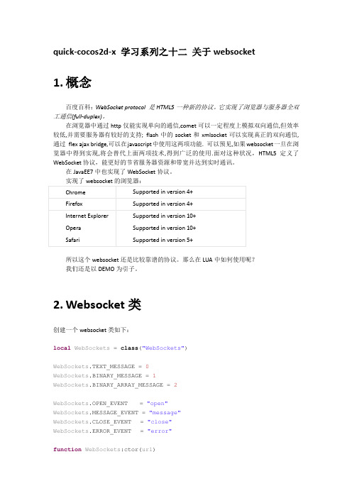
quick-cocos2d-x 学习系列之十二关于websocket1.概念百度百科:WebSocket protocol 是HTML5一种新的协议。
它实现了浏览器与服务器全双工通信(full-duplex)。
在浏览器中通过http仅能实现单向的通信,comet可以一定程度上模拟双向通信,但效率较低,并需要服务器有较好的支持; flash中的socket和xmlsocket可以实现真正的双向通信,通过flex ajax bridge,可以在javascript中使用这两项功能. 可以预见,如果websocket一旦在浏览器中得到实现,将会替代上面两项技术,得到广泛的使用.面对这种状况,HTML5定义了WebSocket协议,能更好的节省服务器资源和带宽并达到实时通讯。
在JavaEE7中也实现了WebSocket协议。
实现了websocket的浏览器:所以这个websocket还是比较靠谱的协议。
那么在LUA中如何使用呢?我们还是以DEMO为引子。
2.Websocket类创建一个websocket类如下:local WebSockets = class("WebSockets")WebSockets.TEXT_MESSAGE = 0WebSockets.BINARY_MESSAGE = 1WebSockets.BINARY_ARRAY_MESSAGE = 2WebSockets.OPEN_EVENT = "open"WebSockets.MESSAGE_EVENT = "message"WebSockets.CLOSE_EVENT = "close"WebSockets.ERROR_EVENT = "error"function WebSockets:ctor(url)cc(self):addComponent("components.behavior.EventProtocol"):exportMeth ods()self.socket = cc.WebSocket:create(url)if self.socket thenself.socket:registerScriptHandler(handler(self, self.onOpen_), cc.WEBSOCKET_OPEN)self.socket:registerScriptHandler(handler(self,self.onMessage_), cc.WEBSOCKET_MESSAGE)self.socket:registerScriptHandler(handler(self, self.onClose_), cc.WEBSOCKET_CLOSE)self.socket:registerScriptHandler(handler(self, self.onError_), cc.WEBSOCKET_ERROR)endendfunction WebSockets:isReady()return self.socket and self.socket:getReadyState() ==cc.WEBSOCKET_STATE_OPENendfunction WebSockets:send(data, messageType)if not self:isReady() thenprintError("WebSockets:send() - socket is't ready")return falseendmessageType = checkint(messageType)self.messageType = messageTypeif messageType == WebSockets.TEXT_MESSAGE thenself.socket:sendString(tostring(data))elseif messageType == WebSockets.BINARY_ARRAY_MESSAGE then data = checktable(data)self.socket:sendString(data, table.nums(data))elseself.socket:sendString(tostring(data))endreturn trueendfunction WebSockets:close()if self.socket thenself.socket:close()self.socket = nilendself:removeAllEventListeners()endfunction WebSockets:onOpen_()self:dispatchEvent({name = WebSockets.OPEN_EVENT})endfunction WebSockets:onMessage_(message)local params = {name = WebSockets.MESSAGE_EVENT,message = message,messageType = self.messageType}self:dispatchEvent(params)endfunction WebSockets:onClose_()self:dispatchEvent({name = WebSockets.CLOSE_EVENT})self:close()endfunction WebSockets:onError_(error)self:dispatchEvent({name = WebSockets.ERROR_EVENT, error = error}) endreturn WebSockets3.MainScene调用该类的场景MainScene,如下。
cocos2d-x引擎介绍PPT课件

cocos2d-x是一款流行的开源游戏引擎,它基于C语言编写,支持跨平台开发,包括iOS 、Android、Windows、Mac等平台。cocos2d-x提供了丰富的游戏开发工具和功能, 包括场景管理、粒子系统、物理引擎等。
游戏框架
游戏框架定义
游戏框架是一个为游戏开发者提供的软件开发框架,它提供了一套完整的游戏开发解决方案,包括游戏逻辑、图形渲 染、物理模拟等。
02 游戏开发中的核心概念
游戏引擎
游戏引擎定义
游戏引擎是一个为游戏开发者提供的一套软件开发工具包,用于构建游戏。它集成了游戏 开发所需的各种核心功能,包括图形渲染、物理模拟、音频处理等。
游戏引擎的重要性
游戏引擎是游戏开发的核心,它简化了游戏开发的过程,提高了开发效率,使开发者能够 专注于游戏的创意和玩法设计。
虚拟现实与增强现实
随着VR和AR技术的不断发展, 未来的游戏将更加沉浸式和交 互式。
云游戏
随着云计算技术的进步,云游戏 将逐渐成为主流,玩家可以在任 何设备上随时随地畅玩游戏。
人工智能与机器学习
AI和机器学习技术在游戏中的 应用将更加广泛,例如智能 NPC、自适应游戏难度等。
跨平台社交
未来的游戏将更加注重社交互动 ,玩家可以在不同平台上与好友
高效资源管理
cocos2d-x提供高效的资源管理机 制,确保游戏在跨平台运行时能够 快速加载和释放资源。
丰富的游戏开发工具
cocos2d-x Studio
性能分析和优化工具
提供可视化的编辑器,支持场景编辑、 动画制作、UI设计等功能,提高游戏 开发效率。
内置性能分析工具,帮助开发者实时 监控游戏运行状态,发现性能瓶颈并 进行优化。
Cocos2d-x(1)CCAction动作机制

Cocos2d-x(1)CCAction动作机制动作机制ActionCCAction是动作类的基类,所有的动作都派⽣⾃这个类,它创建的⼀个对象代表了⼀个动作。
动作作⽤于CCNode,因此,任何⼀个动作都需要由CCNode对象来执⾏。
以下代码实现了⼀条鱼⽤1 秒钟的时间移动到了(0, 0)点:CCSprite* sprite = CCSprite ::create("fish.png");CCAction* action = CCMoveTo ::create(1.0f, ccp(0, 0));sprite->runAction(action);值得注意的是,⼀个 CCAction只能使⽤⼀次,这是因为动作对象不仅描述了动作,还保存了这个动作持续过程中不断改变的⼀些中间参数。
对于需要反复使⽤的动作对象,可以通过copy⽅法复制使⽤。
CCAction作为⼀个基类,其实质是⼀个接⼝(即抽象类),由它派⽣的实现类(如运动和转动等)才是我们实际使⽤的动作。
CCAction的绝⼤多数实现类都派⽣⾃ CCFiniteTimeAction,这个类定义了在有限时间内可以完成的动作。
CCFiniteTimeAction定义了reverse ⽅法,通过这个⽅法可以获得⼀个与原动作相反的动作(称作逆动作),例如隐藏⼀个精灵后,⽤逆转动作再显⽰出来。
当然,并⾮所有的动作都有对应的逆动作,例如类似" 放⼤到" 等设置属性为常量的动作不存在逆动作,⽽设置属性为相对值的动作则往往存在相应的逆动作。
关于逆动作,后⾯将会看到更多演⽰。
由CCFiniteTimeAction派⽣出的两个主要类分别是瞬时动作(CCActionInstant )和持续性动作(CCActionInterval),这两类动作与4.4 节中介绍的复合动作配合使⽤,能得到复杂⽣动的动作效果。
如图,为CCAction的继承关系图-----------------------CCAction-的分割线----------------------------------------------------2.瞬时动作(CCActionInstant )瞬时动作是指能⽴刻完成的动作,是 CCFiniteTimeAction中动作持续时间为 0 的特例。
龙图教育:Cocos2d-x3.0新的触摸机制介绍
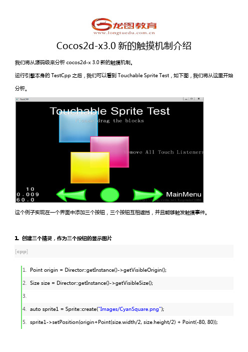
Cocos2d-x3.0新的触摸机制介绍我们将从源码级来分析cocos2d-x 3.0新的触摸机制。
运行引擎本身的TestCpp之后,我们可以看到Touchable Sprite Test,如下图,我们将从这里开始分析。
这个例子实现在一个界面中添加三个按钮,三个按钮互相遮挡,并且能够触发触摸事件。
1. 创建三个精灵,作为三个按钮的显示图片[cpp]1.Point origin = Director::getInstance()->getVisibleOrigin();2.Size size = Director::getInstance()->getVisibleSize();3.4.auto sprite1 = Sprite::create("Images/CyanSquare.png");5.sprite1->setPosition(origin+Point(size.width/2, size.height/2) + Point(-80, 80));6.addChild(sprite1, 10);7.8.auto sprite2 = Sprite::create("Images/MagentaSquare.png");9.sprite2->setPosition(origin+Point(size.width/2, size.height/2));10.a ddChild(sprite2, 20);11.a uto sprite3 = Sprite::create("Images/YellowSquare.png");12.s prite3->setPosition(Point(0, 0));13.s prite2->addChild(sprite3, 1);2. 创建一个单点触摸事件监听器,在监听器中完成逻辑处理[cpp]1.// 创建一个事件监听器 OneByOne 为单点触摸2.auto listener1 = EventListenerTouchOneByOne::create();3.// 设置是否吞没事件,在 onTouchBegan 方法返回 true 时吞没4.listener1->setSwallowTouches(true);5.6.// 使用 lambda 实现 onTouchBegan 事件回调函数7.listener1->onTouchBegan = [](Touch* touch, Event* event){8.// 获取事件所绑定的 target9. auto target = static_cast<Sprite*>(event->getCurrentTarget());10.11.// 获取当前点击点所在相对按钮的位置坐标12. Point locationInNode = target->convertToNodeSpace(touch->getLocation());13. Size s = target->getContentSize();14. Rect rect = Rect(0, 0, s.width, s.height);15.16.// 点击范围判断检测17.if (rect.containsPoint(locationInNode))18. {19. log("sprite began... x = %f, y = %f", locationInNode.x, locationInNode.y);20. target->setOpacity(180);21.return true;22. }23.return false;24.};25.26.// 触摸移动时触发27.l istener1->onTouchMoved = [](Touch* touch, Event* event){28. auto target = static_cast<Sprite*>(event->getCurrentTarget());29.// 移动当前按钮精灵的坐标位置30. target->setPosition(target->getPosition() + touch->getDelta());31.};32.33.// 点击事件结束处理34.l istener1->onTouchEnded = [=](Touch* touch, Event* event){35. auto target = static_cast<Sprite*>(event->getCurrentTarget());36. log("sprite onTouchesEnded.. ");37. target->setOpacity(255);38.// 重新设置 ZOrder,显示的前后顺序将会改变39.if (target == sprite2)40. {41. sprite1->setZOrder(100);42. }43.else if(target == sprite1)44. {45. sprite1->setZOrder(0);46. }47.};3. 添加事件监听器到事件分发器[cpp]1.// 添加监听器2._eventDispatcher->addEventListenerWithSceneGraphPriority(listener1, sprite1);3._eventDispatcher->addEventListenerWithSceneGraphPriority(listener1->clone(), sprite2);4._eventDispatcher->addEventListenerWithSceneGraphPriority(listener1->clone(), sprite3);_eventDispatcher是Node的属性,通过它管理当前节点(如场景、层、精灵等)的所有事件分发情况。
科大讯飞AIUI集成指引-讯飞开放平台
5
科大讯飞 AIUI 集成指南
// 4.向AIUI服务发送各种消息,以msgType字段区分类型,可携带参数和数据。如:
IAIUIMessage * wakeupMsg = IAIUIMessage::create(AIUIConstant::CMD_WAKEUP); agent->sendMessage(wakeupMsg); wakeupMsg->destroy();
2
科大讯飞 AIUI 集成指南
1. 概述
该 SDK 用于接入科大讯飞 AIUI 开放云平台服务。支持 Linux, Windows 平台,提供的 接口为 C++形式。Android 平台提供的 Java 接口文档请参考 / 。 iOS 平 台 AIUI 接口一样,可参考该文档。
SDK 使用方法 .................................................................................................................. 3 3.1. 3.2. 3.3. 3.4. 3.5. 调用流程简介 ............................................................................................................ 3 主要类接口介绍 ........................................................................................................ 3 接口调用 .................................................................................................................... 4 事件处理 .................................................................................................................... 6 参数设置 .................................................................................................................... 7
cocos2dX显示中文字符和解析XML文件
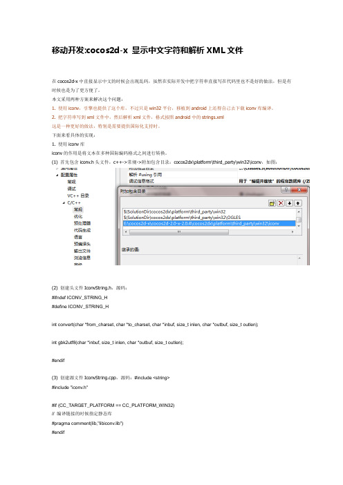
移动开发:cocos2d-x 显示中文字符和解析XML文件在cocos2d-x中直接显示中文的时候会出现乱码,虽然在实际开发中把字符串直接写在代码里也不是好的做法,但是有时候也是为了更方便了。
本文采用两种方案来解决这个问题:1. 使用iconv,引擎也提供了这个库,不过只是win32平台,移植到android上还得自己去下载iconv库编译。
2. 把字符串写到xml文件中,然后解析xml文件,格式按照android中的strings.xml这是一种更好的做法,特别是需要提供国际化支持时。
下面来看具体的实现:1. 使用iconv库iconv的作用是将文本在多种国际编码格式之间进行转换。
(1) 首先包含iconv.h头文件,c++->常规->附加包含目录:cocos2dx\platform\third_party\win32\iconv,如图:(2) 创建头文件IconvString.h,源码:#ifndef ICONV_STRING_H#define ICONV_STRING_Hint convert(char *from_charset, char *to_charset, char *inbuf, size_t inlen, char *outbuf, size_t outlen);int gbk2utf8(char *inbuf, size_t inlen, char *outbuf, size_t outlen);#endif(3) 创建源文件IconvString.cpp,源码:#include <string>#include "iconv.h"#if (CC_TARGET_PLATFORM == CC_PLATFORM_WIN32)// 编译链接的时候指定静态库#pragma comment(lib,"libiconv.lib")#endifint convert(char *from_charset, char *to_charset, char *inbuf, size_t inlen, char *outbuf, size_t outlen){iconv_t iconvH;iconvH = iconv_open(to_charset, from_charset);if( !iconvH ) return NULL;memset(outbuf, 0, outlen);#if(CC_TARGET_PLATFORM == CC_PLATFORM_WIN32)const char *temp = inbuf;const char **pin = &temp;char **pout = &outbuf;if( !iconv(iconvH, pin, &inlen, pout, &outlen) ){iconv_close(iconvH);return NULL;}#elseif( !iconv(iconvH, &inbuf, &inlen, &outbuf, &outlen) ){iconv_close(iconvH);return NULL;}#endificonv_close(iconvH);return NULL;}int gbk2utf8(char *inbuf, size_t inlen, char *outbuf, size_t outlen){return convert("gb2312", "utf-8", inbuf, inlen, outbuf, outlen);}代码比较简单,需要注意的是win32和android对应的iconv函数参数不一样。
我的cocos2D-x3.10安装之路

WIN10系统安装VS2015+Cocos-X3.10方法经过长时间的摸索与尝试Cocos2D-X3.10 终于可以在Windows10上运行了。
Cocos2D-X3.10的安装和配置个人觉得还是比较麻烦的,主要在于它不像其他软件一键安装就能使用,而在于安装Cocos的同时还要附加其他安装软件和组件,例如Python、JDK、NDK、ANT等,而这些组件又有不同的版本,版本的选择如果不正确就会导致Cocos 无法运行或无法打包生成APK。
目前,Cocos2D-x 支持Win32、Android、iOS 三个平台的开发,本文分别介绍在windows和Android环境下的开发环境搭建。
一个完整的开发环境包括开发、编译、链接、运行和调试等几部分,所以需要相应的开发环境,比如Win32 环境下的VS(Visual Studio,微软公司集成开发环境),Android 的开发环境Eclipse 和Android SDK 等,iOS 则需要Xcode环境,然后使用Cocos2D-x 的模板编译出相应环境的软件包。
一般情况下,使用Cocos2D-x 的开发流程是:首先在VS 环境中进行开发调试,之后分别在另外两个平台的开发环境中编译生成相应的软件包。
当然,如果是首先使用Cocos2DiPhone进行开发,并使用Cocos2D-x 进行Android 版本移植的,一般先在Xcode 环境中进行开发,然后使用Android 的开发环境进行开发。
下面我们就开始搭建跨平台的开发环境。
1.安装VS2015下载地址:链接:/s/1eS363Km 密码:eqdh搭建Windows 下的Cocos2D-x 开发环境,首先需要安装VS,它可以用来创建Windows 平台下的Windows 应用程序、网络应用以及网络服务等,支持的语言包括C++、Basic、C# 等。
双击安装文件,便可以开始安装,默认安装即可。
如果是自定义安装,应选中Visual C++ 组件。
- 1、下载文档前请自行甄别文档内容的完整性,平台不提供额外的编辑、内容补充、找答案等附加服务。
- 2、"仅部分预览"的文档,不可在线预览部分如存在完整性等问题,可反馈申请退款(可完整预览的文档不适用该条件!)。
- 3、如文档侵犯您的权益,请联系客服反馈,我们会尽快为您处理(人工客服工作时间:9:00-18:30)。
从零开始掌握视频教程第季瓦片地图
课程目标
让学员掌握瓦片地图的使用方法。
适用人群
任何对感兴趣的学员
课程简介
本套教程的目标是让初学者快速掌握的基本开发技术(包括开发环境的搭建、、、、等,这些技术都是开发游戏必备的技术。
并且可以利用本套教程讲解的技术实现一个射击类游戏:星空大战。
对本套教程感兴趣的学员可以加入群:
购买本课程的学员请加入付费学员群:加入时需要提供账号
加入时请阐明主要使用的游戏开发技术,如、等。
适合对象:
•想从事游戏开发,但从没有接触过游戏开发的程序员。
•以前开发过游戏,但从没使用过跨平台开发引擎的程序员。
•以前使用过或,但希望学习的程序员。
•所有对游戏开发有着浓厚兴趣的程序员和非程序员。
学习条件:
虽然本课程是的入门课程,但仍然要求学员有一定的知识储备。
基本的要求如下:
1.了解、或中至少一个操作系统的基本操作。
2.掌握、和中至少一个的基本操作。
3.了解的基本开发知识
课程
[免费观看]
分钟
本讲主要介绍了支持的地图样式以及应用场景。
[免费观看]
分钟
本讲主要介绍了地图编辑器()的基本情况,包括格式的地图文件,下载地址以及主要特性和功能。
分钟
本讲主要介绍了如何使用来创建和编辑地图。
其中包括新建鸟瞰地图、角地图、创建和导入图块,设置图块属性,添加图层、移动地图、改变地图尺寸等功能。
分钟
本讲主要介绍了如何在中将一个用制作的地图文件(文件)显示在屏幕上。
分钟
分钟
本讲主要介绍了如何获取图块的,并且根据图块的获取图块的属性值信息。
通过图块的属性,可以实现图块的特殊特性。
例如,对于表示墙的图块,精灵是不能穿过的,这就要求精灵在移动时检测当前正要穿过的图块的属性值。
分钟
本讲主要介绍了如何复制、移动和删除地图上的图块。
这也充分说明了地图是可编辑的,这一点不同于普通的背景图。