B2001RU中文资料
Insulin中文说明书

l
2001-07
374
概述:
胰岛素是一分子量约为6000D的激素肽,由胰岛的B细胞分泌,经门静脉和肝脏进 入血循环。胰岛素的释放呈波段性,并紧随血糖分泌周期之后,约迟2分钟。 胰岛素由二条肽链组成,a-链含21个氨基酸,β-链含30个氨基酸。胰岛的B细胞先 合成单链的前胰岛素原,随后迅速裂解成前胰岛素。特异的蛋白酶再将前胰岛素裂 解成胰岛素和C-肽。全部的C-肽和一半的胰岛素即刻被释放进入血流,另一半的胰 岛素被储留在肝脏。 血循环中的胰岛素半衰期为3-5分钟,主要在肝脏降解。前胰岛素和C-肽主要在肾 脏灭活和排泄。 胰岛素的氨基酸序列在进化过程中高度保守。因此,在基因工程人胰岛素之前,已 成功将猪或牛胰岛素用于糖尿病的治疗。 胰岛素的生理作用通过特异的受体传导,主要通过肝脏、脂肪组织和肌肉系统的细 胞摄取血糖,这是胰岛素降血糖作用的基础。 血清胰岛素检测主要用于针对低血糖患者。可帮助了解葡萄糖/胰岛素比值和有关 胰岛素分泌情况,如甲糖宁试验、胰高血糖素试验、口服葡萄糖耐量试验及饥饿激 发试验等。 尽管胰腺合成胰岛素的量经常是通过测定C-肽来判定,但仍有必要测定胰岛素。例 如,治疗剂量的非人源性胰岛素可导致产生抗胰岛素抗体。在这些病例中,检测血 清胰岛素的浓度反映了游离的、具有生理活性的胰岛素含量,而C-肽测定反映的是 内源性胰岛素分泌的总量。 胰岛素代谢紊乱可对许多代谢过程产生重大影响。游离的、具有生理活性的胰岛素 含量过低,可导致糖尿病。部分原因可能是β-细胞的破坏(I型糖尿病)、胰岛素 活性降低或胰腺合成减少(II型)、循环抗胰岛素抗体、胰岛素释放延迟或胰岛素 受体缺乏(不足)。 另一方面,自发的、不规则的胰岛素分泌是低血糖的常见原因。这种状况下糖原异 生被抑制,可见于严重的肝、肾功能衰竭,胰岛细胞瘤或癌。也有假性低血糖症。 糖耐量降低人群中有3%的人其代谢状况经一段时间后会恶化成糖尿病。怀孕期间糖 耐量降低需要治疗。胎儿死亡危险性的明显升高要求加强监测。 Elecsys 胰岛素试验采用了二种人胰岛素特异的单克隆抗体。 原理: 采用双抗体夹心法,整个过程18分钟完成。 · 第1步:20µl标本、生物素化的抗胰岛素单克隆抗体和钌(Ru)标记的抗胰岛素 单克隆抗体混匀,形成夹心复合物。 · 第2步:加入链霉亲和素包被的微粒,让上述形成的复合物通过生物素与链霉 亲和素间的反应结合到微粒上。 · 第3步:反应混和液吸到测量池中,微粒通过磁铁吸附到电极上,未结合的物质 被清洗液洗去,电极加电压后产生化学发光,通过光电倍增管进行测定。 ·检测结果由机器自动从标准曲线上查出。此曲线由仪器通过2点定标校正,由从 试剂条形码扫描入仪器的原版标准曲线而得。 试剂: M:链霉亲和素包被的微粒(透明瓶盖),1瓶,6.5ml。粒子浓度0.72mg/ml,生物
_城市规划学刊_投稿指南
要求准确得体 ! 简短精炼 ! 外延和 内涵恰如其 分 " 若简短题名不足 以显示论文内容或反映 出属于系列 研究 的性质 , 可加 副标题 来补充说 明特 定的对 象 !
方法及 内容等信息 "
麟, 陈 宝 明, 赵 琼, 等, 译. 高 等 教 育 出 版 社,
2 0 1 0: 1 1 8 . (以 L KE R
= ] 深圳 市规划局. 中 国城 市规划设计研 究院. 深 4 圳市经济特区总体规划 = R2 . 198 6 : 10 .
(p l日 n n jn g Ch 万 na
M aste r
(5 )
参考文献的标注与排序
参 考文献在 正文 中以 / (作者姓 名 , 年份 ) . 的形 式进行标 注 ; 文后所有参考文献按作者姓的英
tion of urban Pl己 nning 1. Beijjng: Chi no Ar一
eh ite etu re Ind u st ry p re ss . 1 98 0)
以黑 白线条 明确表达 的建议采 用黑 白图形式 " . 注释格式 : 注释 是对文章 中的语汇 ! 内容 ! 引文等作介绍 ! 说 明 ! 评议的文字 , 而不是 简单标 明资料来源之用 " 正文 中位置依据先后顺序 以上标
引 用的插 图和表格 , 而注 明资料来源 , 资料来 源信息格式参见参考文献格式 "
插 图排入 正文 w o r d 文档 , 并另附. t计格 式文 件 , 要求 300dpi 以上 , 接受彩 色和 黑白插 图 " 照 片和 规划设 计 图纸 以彩 色为主 , . 幻s x 格式 文件可
(S HE N 树 eie卜 e n g. T he
BRUBXXX中文资料
Tel : 01209 215424 Fax : 01209 215197
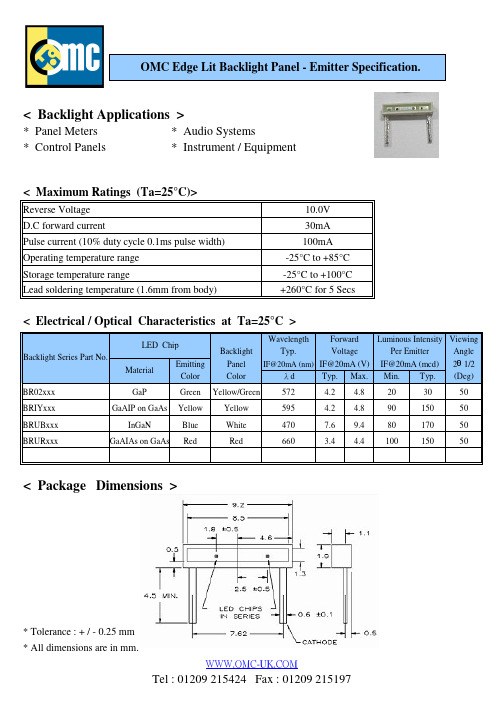
Emitting Color
Backlight Panel Color
Forward Luminous Intensity Viewing Voltage Per Emitter Angle 2 1/2 IF@20mA (nm) IF@20mA (V) IF@20mA (mcd) d Typ. Max. Min. Typ. (Deg) 50 50 50 50
< Maximum Ratings (Ta=25°C)>
Reverse Voltage D.C forward current Pulse current (10% duty cycle 0.1ms pulse width) Operating temperature range Storage temperature range Lead soldering temperature (1.6mm from body) 10.0V 30mA 100mA -25°C to +85°C -25°C to +100°C +260°C for 5 Secs
元器件交易网
OMC Edge Lit Backlight Panel - Emitter Specification.
< Backlight Applications >
* Panel Meters * Control Panels * Audio Systems * Instrument / Equipment
67.00 xreen Bi-Colour
523-227
67.00 x 28.00 x 3.0mm
67.00 x 23.00mm
B2001RW中文资料

Key Features:• 20W Output Power• 2:1 Input Voltage Range • 1,500 VDC Isolation• Compact 1 x 2 Inch Case • Single & Dual Outputs • Optional Remote ON/OFF •Industry Standard Pin-OutB2000RW Compact 1 x 2 Inch 20W Wide Input Range DC/DC Con v ert e rsSeriesInputParameter Conditions Min.Typ.Max.Units Input Start Voltage12 VDC Input 8.68.89.0VDC 24 VDC Input 17.017.518.048 VDC Input 34.035.036.0Input Filter (Pi) Filter (Complies with EN55022 Class “A”)Reverse Polarity Input Current 2.0A Short Circuit Input Power3,500mW OutputParameterConditionsMin.Typ.Max.Units Output Voltage Accuracy ±0.5±1.0%Output Voltage Balance Dual Output , Balanced Loads±0.5±2.0%Line Regulation Vin = Min to Max ±0.1±0.3%Load RegulationIout = 10% to 100%±0.1±0.5%Ripple & Noise (20 MHz) (Note 1)5580mV P - P Ripple & Noise (20 MHz)Over Line, Load & Temp.100mV P - P Ripple & Noise (20 MHz)10mV rms Output Power Protection110160%Transient Recovery Time (Note 2)25% Load Step Change150300µSec Transient Response Deviation ±2.0±4.0%Temperature Coeffi cient ±0.01±0.02%/°C Output Short CircuitContinuous (Autorecovery)GeneralParameterConditionsMin.Typ.Max.Units Isolation Voltage60 Seconds1,500VDC Isolation Test Voltage Flash Tested For 1 Sec1,650VDC Isolation Resistance 500 VDC 1,000M ⍀Isolation Capacitance 100 kHz, 1V1,2001,500pF Switching Frequency290330360kHzRemote On/Off (Note 3)Parameter ConditionsMin.Typ.Max.Units Supply On 2.5100.0VDC Supply Off0.01.0VDCStandby Input Current 25mAControl CommonReferenced to Negative Input (pin 2)EnvironmentalParameterConditionsMin.Typ.Max.Units Operating Temperature Range Ambient -40+25+50°C Operating Temperature Range Case+105°C Storage Temperature Range -50+125°C Cooling Free Air ConvectionHumidity RH, Non-condensing95%RFISix-Side Shielded Metal CaseConducted EMI EN55022 Class “A”Physical Case Size 2.0 x 1.0 x 0.40 Inches (50.8 x 25.4 x 10.2 mm)Case Material Metal with Non-Conductive BaseWeight1.06 Oz (30g)Reliability Specifi cationsParameter ConditionsMin.Typ.Max.Units MTBFMIL HDBK 217F , 25°C, Gnd Benign800kHours Absolute Maximum RatingsParameterConditionsMin.Typ.Max.Units Input Voltage Surge (1 Sec)12 VDC Input -0.725.0VDC 24 VDC Input -0.750.048 VDC Input-0.7100.0Lead Temperature1.5 mm From Case For 10 Sec260.0°C Internal Power DissipationAll Models4,500mWCaution: Exceeding Absolute Maximum Ratings may damage the module. These are not continuous operating ratings.MicroPower Direct292 Page Street Suite DStoughton, MA 02072USAT: (781) 344-8226F: (781) 344-8481E: sales@ W: Electrical Specifi cationsSpecifi cations typical @ +25°C, nominal input voltage & rated output current, unless otherwise noted. Specifi cations subject to change without notice.Model Number Input Refl ectedRippleCurrent(mA, Typ)Output OverVoltageProtection(VDC)Effi ciency(%, Typ)CapacitiveLoad(µF Max)Fuse RatingSlow-Blow(mA) Voltage (VDC)Current (mA)Voltage(VDC)Current(mA, Max)Current(mA, Min)Nominal Range Full-Load No-LoadB2001RW129.0 - 18.01,3583050 3.34,000.0240.0 3.9814704,000B2002RW129.0 - 18.01,9843050 5.04,000.0240.0 6.8844704,000B2003RW129.0 - 18.01,898305012.01,670.0100.015.0884704,000B2004RW129.0 - 18.01,903305015.01,340.080.018.0884704,000B2005RW129.0 - 18.01,8983050±12.0±835.0±50.0±15.088±2204,000B2006RW129.0 - 18.01,9033050±15.0±670.0±40.0±18.088±2204,000B2011RW2418.0 - 36.06711730 3.34,000.0240.0 3.9824702,000B2012RW2418.0 - 36.09801730 5.04,000.0240.0 6.8854702,000B2013RW2418.0 - 36.0938173012.01,670.0100.015.0894702,000B2014RW2418.0 - 36.0941173015.01,340.080.018.0894702,000B2015RW2418.0 - 36.09381730±12.0±835.0±50.0±15.089±2202,000B2016RW2418.0 - 36.09411730±15.0±670.0±40.0±18.089±2202,000B2021RW4836.0 - 75.03351020 3.34,000.0240.0 3.9824701,000B2022RW4836.0 - 75.04901020 5.04,000.0240.0 6.8854701,000B2023RW4836.0 - 75.0469102012.01,670.0100.015.0894701,000B2024RW4836.0 - 75.0471102015.01,340.080.018.0894701,000B2025RW4836.0 - 75.04691020±12.0±835.0±50.0±15.089±2201,000B2026RW4836.0 - 75.04711020±15.0±670.0±40.0±18.089±2201,000 Model Selection GuideMechanical DimensionsHeatsink Notes:• Use of the heatsink will extend the units operating temperaturerange by approximately 10°C.• The heatsink is black anodized aluminum.MicroPower DirectWe Power Your Success - For Less!292 Page Street Ste D Stoughton, MA 02072 • TEL: (781) 344-8226 • FAX: (781) 344-8481 • E-Mail: sales@ Heatsink Dimensions (Optional)For heatsink option, add suffi x “H” to model number (i.e. B2003RW-H) For Remote Control option, add suffi x “R” to model number (i.e. B2003RW-R)Mechanical Notes:• All dimensions are typical in inch e s (mm)• Tolerance x.xx = ±0.01 (±0.25)Pin Single Dual1+Vin+Vin2-Vin-Vin3+Vout+Vout4No Pin Comm.5-Vout-Vout6ON/OFF ON/OFFPin ConnectionsDerating CurveNotes:1. When measuring output ripple, it is recommended that an external 1.0 µF ceramic capacitor be placed fromthe +Vout pin to the -Vout pin for single output units and from each output to common for dual output units.2. Transient recovery is measured to within a 1% error band for a load step change of 75% to 100%.3. The maximum control current at the on/off pin (pin 6) during a logic high is 5 µA. The maximum control currentto the on/off pin at logic low is -100 µA. If the on/off pin is left open, the unit operates. If it is grounded, theunit will shut off.4. Operation at no-load will not damage these units. However, they may not meet all specifi cations.5. Dual output units may be connected to provide a 24 VDC or 30 VDC output. To do this, connect the load acrossthe positive (+Vout) and negative (-Vout) outputs and fl oat the output common.6. The converter should be connected to a low ac-impedance source. An input source with a highly inductiveimpedance may affect the stability of the converter. In applications where the converter output loading is highand input power is supplied over long lines, it may be necessary to use a capacitor on the input to insurestart-up.In this case, it is recommended that a low ESR (ESR <1.0 at 100 kHz) capacitor be mounted close to theconverter. For 12V input units, a 22.0 µF is recommended; for 24V & 48V units a 6.8 µF.7. It is recommended that a fuse be used on the input of a power supply for protection. See the table above forthe correct rating.。
钌

制备方法
钌衍生自铂金属矿石。生产方法取决于矿石类型。但是,萃取过程与其他贵金属(参见铂,铑和铱)相似。 像铑一样,钌可以从某些类型的矿石电解精炼镍或铜时,从累积的阳极污泥中获得。钌元素存在于铱和的天然合 金(铱,亚硫酸盐)中,硫化物和其他矿石(戊铁矿,月桂石等)中也有少量商业上可回收的 。
通过与王水处理(分离不溶的铑,钌和铱),与硫酸氢钠(与铑起反应)融合以及与过氧化钠融合(与硅酸 钠溶解)的顺序将元素与其他铂金属分离。用乙醇处理所得的钌酸和渗透酸溶液,以沉淀出二氧化钌 。
研究简史
钌的发现过程 :钌是铂系元素中在地壳中含量最少的一个,也是铂系元素中最后被发现的一个。它在铂被 发现100多年后,比其余铂系元素晚40年才被发现。不过,它的名字早在1828年就被提出来了。当时俄国人在乌 拉尔发现了铂的矿藏,塔尔图大学化学教授奥桑首先研究了它,认为其中除了铂外,还有三个新元素。奥桑把他 分离出的新元素样品寄给了贝齐里乌斯,贝齐里乌斯认为其中只有pluranium一个是新金属元素,其余的分别是 硅石和钛、锆以及铱的氧化物的混合物。
2、钌系电阻浆料:电导电材料(二氧化钌、钌酸铋、钌酸铅等)玻璃粘结剂、有机载体等组成的使用最广泛 的一种电阻浆料,具有阻值范围宽、电阻温度系数低、阻值重现性好、环境稳定的性好等优点,用于制作高性能 电阻和高可靠精密电阻络 。
3、超细水合二氧化钌粉:有于生产厚膜电阻浆料或催化剂用的黑色或蓝黑色超细粉未,其中钌的质量分数为 60%~71%。粉未的平均粒度<1.0um,松装密度为0.5~0.9g/cm,振实密度为1.0~1.4g/cm-3。
4、钌基厚膜电阻浆料:由二氧化钌粉、钌酸盐、无机添加物和有机载体组成的一种满足于印制或涂敷的膏状 物,用于厚膜混合集成电路、电阻络。钌电阻浆料的烧成条件为烧成峰值温度840~860℃,峰值温度保温时间 8~10min,烧结周期30~60min。
电气自动化英语日语中文用语集

机电工程词汇中日英对照2001-11-7 日文中文pinin 英文 1 10炭素钢10炭素钢tan shu gan 2 1F 1 层yi chen 3 2直2个班er ge ban 4 AF移载装置总装移载装置zhong zhuan yi zai zhuan ji 5 OHC 空中线输送机kong zhong xian shu song ji OHC 6 PBS 入口待装车体储存区入口dai zhuang che ti cun chun qu ru kou 7 PBS 待装车体储存线dai zhuang che ti cun chun xian 8 PVC涂布涂PVC tu PVC 9 T 定规T形尺xing chi T SQUARE10 溶接电弧焊dian hu han ARC WELDING11 叉臂cha bi ARM/LIMP12 主意zhu yi IDEA13 光洁度guan jie du14 促进剂cu jin jiALTAX15 扇形键shan xin jian ALFA KEY16 铝lu ALUMINIUM17 (齿轮)根切qi lungen que UNDER CUT18 止退器zhi tui qi19 锑ti anti20 内侧nei ceINSIDE21 智能的灵活的zhi neng deling huo de INTELLIGENT22 渐开线jian kai xiang INVOLUTE23 蜗轮wo lun WORM GEAR24 蜗轮wo lun WORM WHEEL25 尿烷轮、摩擦轮niao wan lun .mo cha lun URETHANE-WHEEL26 充气器chong qi qi AERATOR27 能源neng yuan ENERGY28 接油盘jie you pan OIL-PAN29 选择、任选项xuan ze ren xuan xiang OPTION30 碳刷tang shua CARBON31 管煤气管mei qi guan GAS PIPE32 溶接气焊qi hang GAS WELDING33 盖、罩gai zhao COVER34 键jian KEY35 、车轮底轮、小脚轮di lun xiao jiao lun CASTOR36 齿轮马达qi lun ma da GEAR MOTOR37 吊具diao ju CARRIER38 きりもみ捻钻nian zuan39 银银镍yin nie NI SILVER40 离合器li he qi CLUTCH41 离合器、制动装置li he qi zhi dong zhuan zhi CLUTCH BRAKE42 润滑脂run hua zhi GREASE43 入带润滑脂轴承dai run hua zhi zhou cheng44 蠕变、爬行ru bian pa xing CREEP45 起重机qi zhong ji CRANE46 闭式连接链bi shi lian jie lian CLOSED JOINT CHAIN47 公用、环球gong yong huan qiu GLOBAL48 沟、槽gou .cao GROOVE49 铬ge50 钢铬钢ge gang51 素硅gui52 表规biaogui gauge53 箱、盒、壳xiang.he .ke CASING54 合金铅青铜轴承合金qian qing tong zhou cheng he jin KELMET ALLOY55 减速器减速器jia su qi REDUCER56 项圈链xian quan lian COIL CHAIN57 绕线弹簧rao xian tan huan58 、栓栓COCK59 销shuan .xiao COTTER60 开口销kai kou xiao COTTER PIN 61 継ぎ手销接头xiao jie tou 62 钴gu 63 橡胶密封xiang jiao mi feng GOM-SEAL 64 注解、注释说明zhu jie zhu shi shuo ming COMMENT 65 、小型小型xiao xing COMPACT 66 圆规yuan gui COMPASS 67 传送机、输送线chuan shong ji shu shong xian CONVEYOR 68 压力波、浪涌ya li be .lang yong SURGING 69 维修部件wei ciu bu jian SERVICE-PARTS 70 周期、循环、中程zhou qi .xun huanzhong cheng CYCLE 71 循环xun huan CYCLO 72 歯形摆线齿形bai xian chi xing CYCLOID 73 侧顶机ce ding ji SIDE LIFT 74 侧辊ce gun SIDE ROLLER 75 无声链wu sheng lian SILENT CHAIN 76 穴锪钻huo zuan 77 鞍形键an xing jian SADDLE KEY 78 维持、保持wei chi bao chi SUPPORT 79 总数zhong shu SUM 80 打磨da mo SANDING 81 密封胶mi feng jiao SEALLER 82 密封mi feng SEAL 83 系统、体系xi tong ti xi SYSTEM 84 塞尺cai chi thickness gauge 85 轴颈zhou jing JOURNAL 86 串联chuan lian SERIES 87 简单、容易jian dan rong yi SIMPLE 88 符号、记号fu hao ji hao SYMBOL 89 整流转换zheng liu zhuan huan SWITCHING 90 螺旋泵luo xuan beng SCREW PUMP 91 简图、草图jian tu qao tu SKETCH 92 锡锡xi TIN 93 机架ji jia STAND 94 步骤/托脚、踏板/台阶bu zhou/tuo jiao ta ban/tai jie STEP 95 停止器ting zhi qi STOPPER 96 存储器、储存线chun cu qi cu chun xian STORAGE 97 蛇行she xing SNAKE 98 蛇形泵she xing beng SNAKEPUMP 99 扳手ban shou SPANNERS100 花键轴hua jian zhou SPLINE101 链轮lian lun SPROCKET102 、空间空间kong jian SPACE103 すべり滑动键hua dong jian104 溶接点焊dian han SPOT WELDING105 止推轴颈zhi tui zhou jing THRUST JORUNAL106 正常正常zheng chang107 断面图、型钢、型材duan mian tu xing gangxing cai108 锯齿形ju chi xing SERRATION109 选择器xuan ze qi SELECTOR110 、选択选择xuna ze SELECT111 せん断剪断jian duan112 区域qu yu ZONE113 插口、插座/孔、锭座cha kou.cha zuo/kong .ding zou SOCKET114 实心轴shi shin zhou SOLID SHAFT115 回转滚柱/倒置滚柱hui zhuan gun zhu /dao zhi gun zhuTURN-ROLLER116 拉模铸造la mo zhu zao DIE CASTING117 型、式xing.shi TYPE118 超时chao shi TIME-OVER119 径节jing jie DIAMETRAL PITCH120 、直接笔直、直接bi zhi zhi jie DIRECT121 、尘受け防尘罩/粉尘罩fang chen zhao /fen chen zhao DUST COVER122 负担、压力fu danya li TAX123 钨wu TUNGSTEN124 钽tan TANTALUM125 链条lian tiao CHAIN126 、検査检测jian ce CHECK127 钛tai TITANIUM128 、管管guan TUBE129 分规fen gui DIVIDER130 磁带、绝缘带ci dai jue yuan dai TAPE131 贴C/V 贴黑窗框tie hei chuang kuang132 溶接铝热焊、热剂焊lv re han re ji hang THERMIT WELDING133 扭力杆niu li gan TORSION BAR SPRING134 移行机yi xing ji TRAVERSER135滴水盘、接油盘di shui pan.jie you pan DRIPPAN136 螺帽luo mao NUT137 需要、必要、要求xu yao .bi yao .yao qiu NEEDS138 镍nie NICKEL139 钢镍铬钢nie ge gang NICKEL-CHROMIUM140 合金镍合金nie he jin141 青铜镍青铜nie qing tong NI BRONZE142 螺丝、螺钉、螺栓、螺旋luo shi .luo ding .luo xuan .luo xuan SCREW143 游标卡尺you biao ka chi VERNIER MICROMETER144 歯车145 、垂直垂直chui zhi VERTICAL146 垂直弯轨chui zhi wan guiVERTICAL-CURVE147 、部品部分、要素、零件、部件bu fen yao su ling jian bu jian PARTS148 双曲面shuang qu mian HYPOID149 下刻痕、下缺口xia ke henxia que kou HYPO-NIEK150 汇流条/工艺电缆hui liu tiao /gong yi dian lang BUS BAR151 ?P停 J?me xing me shi PATTERN152 齿隙间隙回差chi xijian xihui cha BACKLASH153 钒fan VANADIUM154 仕上げ磨光加工mo guang jia gong155弹簧tan huang SPRING156 材料弹簧材料tan huang cai liao SPRING157 仕上げ抛光加工pao guang jia gong158 配合pei he159 棘爪、掣子/锤垫/货架ji zhua zhi zi /chui dian /huo jia PALLET160 托架、滑撬tuo jiahua qiao PALLET161 电动吊车dian dong diao che POWER-TROLLEY162 钩子、吊钩、部件gou zi .diao gou bu jian HANGER163 手柄shuo bing HANDLE164 线弦线xian xian PIANO WIRE165 大圆规da yuan gui BEAM COMPASS166 铋bi BISMUTH167 节距jie ju PITCH168 间隙规jian xi gui pitch gage169 坑、糟、穴、地窖kengcaoxue di jiao PIT170 内藏式nei cang shi BUILD-IN171 销xiao PEEN172 销xiao PIN173 、最终最终zui zhong FINAL174 翼子板、防护板、防冲板yi zi ban fang hu ban fan chong ban FENDER175 叉车cha che FORK-LIFT176 钩、扣、夹子gou kou jia zi HOOK177 推进器、推杆tui jing qi tui gan PUSHER178 推进链条tui jin lian tiao POOTH CHAIN179 仕上げ180 削り铣刀加工xi dao jia gong181 塞子、销子/插头、芯棒sai zi xiao zi /cha tou xin bang PLUG182 刷子shua zi BRUSH183 元电刷yuan dian shua BRUSHLESS184 法兰盘、带凸缘fa lan pandai tu yuan FLANGE185 柱塞泵zhu sai beng PLUNGER PUMP186 空闲线kong xian xiang FREE LINE187 自由导轨、自由滚轮/吊轨zi you dao gui zi you gun lun FREE-RAIL188 地点、位置di dian wei zhi PLACE189 冲床chong chuang PRESS190 拉刀la dao BROACH191 削り192 可编程序的ke bian cheng xu de PROGRAMMABLE193 表示器可编程序显示器ke bian cheng xu xian shi qi PROGRAMMABLE DISPLAY194 工程gong cheng PROJECT195 工艺规程、工艺方法gong yi gui cheng gong yi fang fa PROCESS196 车链che lian BLOCK CHAIN197 鼓风机、增压器gu feng ji zheng ya qi BLOWER198 覆盖层、轴承fu gai ceng zhou cheng BEARING199 轴承滚柱zhou cheng gun zhu BEARING-ROLLER200 基础、底座/灯头ji chu di zuo/deng to.。
RAS错误返回码表

NCRGBNA/GBRU 错误代码说明书B006-6524-A000第二版常用RAS命令表GBNA/GBRU 的错误代码列表变动表REV.日期变动描述主要事务所117/09/2004首次发行228/09/2004添加错误代码.(6604)整理传感器的名称.(FF0D,FF5D) AA08306/10/2004添加错误代码.(3201,6F71) AA09413/10/2004添加命令代码.(ES)添加错误代码.(6103)AA10529/11/2004添加相关的螺线管和传感器.(6108)位置加上所有的错误信息.AA14615/02/2005改变错误信息(1001,2020)添加错误代码.(3501,2502,2503,3510)添加"起因/检查与检验/解决(方法)".(25**,29**) AA17711/03/2005添加错误代码(6703,6704)AA18820/05/2005添加错误信息(72A0)AA20918/01/2006添加错误代码(E211,E213,E30B)AA261021/04/2006添加错误代码(E212,E213,E30C,E30D)添加命令代码.(LN)AA30介绍这个说明书描述了GBNA/GBRU的错误代码.1.错误代码系统一个错误代码由8位字母数字组成.一个错误代码分为3部分.像下面显示的.XXXX+YY+ZZ命令代码+类别+详述第一部分显示的是命令代码.第二部分显示的是检测到的类别错误以及检测的位置.第三部分显示的是详细信息.当一个错误产生的时候,类别和错误代码的详细描述就会显示在PCB板上的LED显示屏上,像下面显示的一样.1秒钟2 秒钟Blink 0.5 秒钟1 秒钟当主机接受命令的时候,就停止显示错误代码.2.象征代码显示LED上,由7节组成.0123456789ABCDEFH-显示在LED上的7节代码.代码实体00一般*一般**: 当ST开关推3秒,代码就会改变.(执行开开关)H0 检查IPL-程序的总和值H1检查内存H2检查外存H3检查启动程序H4 检查文件系统-0 启动程序不足-1 主程序不足-2 用USB下载-3 用SCI下载-4 系统崩溃-5文件系统缺损-6 奇偶错误-7 内存错误-8 没有定义被中断-9 一般的非法指示/非法插槽指示-A 地址错误-B NMI/看门狗错误-C 主程序的总和错误-D 启动程序的总和错误-E USB发送错误-F IPL-程序的总和误差DB在启动程序下开始调试DE终止调试3.命令代码列表(参考"GBNA/GBRU的数据级接口"有关内容的命令)号码代码(H)命令总结15254 RT 复位(软件复位)24854 HT 停止(退出)命令35354 ST 读组件的状态44C44 LD 加载程序54C45 LE 停止加载程序6454B EK 设定加密密钥74650 FP 设定固定参数84350 CP 设定钞箱参数94944 ID 读识别的组件10 4C4E L N 加载组件的序号11 4352 CR 校对纸币的计数器12 5349 SI 读统计信息13 4943 IC 清理统计信息14 4C49 LI 加载统计信息15 5342 SB 读BV的信息16 5652 VR 读验证定单信息17 5347 SG 读纸币识别标志18 534E SN 读纸币序号19 5049 PI 读纸币图案20 4C47 LG 读日志数据21 5359 SY 断电22 4956 IV 接受23 4450 DP 存款24 424B BK 返回接受纸币25 5743 WC 分配26 5050 PP 目前准备27 544F TO 目前28 534F SO 打开快门29 5343 SC 强行关闭快门30 5543 UC 和解31 4243 BC 从临时钞箱返回纸币32 434C CL 收集纸币数据33 534B SK 机械准备34 524A RJ 捕获/拒绝35 4D52 MR 机械复位36 4D4A MJ 卡清理,拒绝和机械复位37 4A41 JA 卡清理准备接受38 4150 AP 自动列出39 5253 RS 远程RAS40 4442 DB 调试41 4553 ES 逃脱纸币(自动清除)4.错误代码(类+详述)错误代码错误消息如何在何时发现错误起因/检测&检验/解决马达/螺线管传感器与FRU 有关0C** 固件的非法功能错误0C00 <固件>从系统管理任务返回系统管理任务已经完成013,307 PC0C01 <固件>不正当的增加功能增加的功能无效.当需要操作的时候,前接受器位于一个意外的位置。
D R I L L S 2001年版商品目录说明书

D R I L L S2001N O T E SiI N D E XFractional Sizes,118°Point,Surface Treated . . . . . . . . . . . . . . . .1600 . . . . .1Fractional Diameters,118°Point,Bright .1600 . . . . .1Fractional Diameters,118°Point,TiN Coated . . . . . . . . . . . . . . . . . . . .1600 . . . . .1Wire Sizes,118°Point,Surface Treated .1601 . . . . .2Wire Sizes,118°Point,Bright . . . . . . . .1601 . . . . .2Wire Sizes,118°Point,TiN Coated . . . . .1601 . . . . .2Letter Sizes,118°Point,Surface Treated .1602 . . . . .3Letter Sizes,118°Point,Bright . . . . . . .1602 . . . . .3Letter Sizes,118°Point,TiN Coated . . . .1602 . . . . .3Metric Sizes,118°Point,Surface Treated 1603 . . . .4–6Metric Sizes,118°Point,Bright . . . . . . .1603 . . . .4–6J O B B E R S L E N G T H , H E A V Y D U T YHigh Speed SteelFractional Sizes,135°Split Point,Surface Treated . . . . . . . . . . . . . . . .1604 . . . . .7Fractional Diameters,135°Split Point,TiN Coated . . . . . . . . . . . . . . . . . . . .1604 . . . . .7Wire Sizes,135°Split Point,Surface Treated . . . . . . . . . . . . . . . .1605 . . . . .8Wire Sizes,135°Split Point,TiN Coated .1605 . . . . .8Letter Sizes,135°Split Point,Surface Treated . . . . . . . . . . . . . . . .1605-A . . . .9Letters Sizes,135°Split TiN Coated . . .1605-A . . . .9CobaltFractional Sizes,135°Split Point,Surface Treated . . . . . . . . . . . . . . . .1606 . . . .10Wire Sizes,135°Split Point,Surface Treated . . . . . . . . . . . . . . . .1607 . . . .11Letter Sizes,135°Split Point,Surface Treated . . . . . . . . . . . . . . . .1608 . . . .12Fractional Sizes,118°Point,Surface Treated . . . . . . . . . . . . . . . .1609 . . .13–14Fractional Sizes,118°Point,Bright . . . . .1609 . . .13–14Wire Sizes,118°Point,Surface Treated .1610 . . . .15Letter Sizes,118°Point,Bright . . . . . . .1611 . . . .16S C R E W M A C H I N E L E N G T H S , H E A V Y D U T YHigh Speed SteelFractional Sizes,135°Split Point,Surface Treated . . . . . . . . . . . . . . . .1612 . . . .17Fractional Sizes,135°Split Point,TiN Coated . . . . . . . . . . . . . . . . . . . .1612 . . . .17Wire Sizes,135°Split Point,Surface Treated . . . . . . . . . . . . . . . .1613 . . . .18Wire Sizes,135°Split Point,TiN Coated .1613 . . . .18Letter Sizes,135°Split Point,Surface Treated . . . . . . . . . . . . . . . .1614 . . . .19CobaltFractional Sizes,135°Split Point,Surface Treated . . . . . . . . . . . . . . . .1615 . . . .20Wire Sizes,135°Split Point,Surface Treated . . . . . . . . . . . . . . . .1616 . . . .21Letter Sizes,135°Split Point,Surface Treated . . . . . . . . . . . . . . . .1617. . . .22R E D U C E D S H A N KHigh Speed Steel1/2" Round Shank S &D,118°Point,Surface Treated . . . . . . . . . . . . . . . .1618 . . . .23S E T SDrill Sets . . . . . . . . . . . . . . . . . . . . . . . . .1619 . . .24–25LIST STYLENO.PAGE Drill Feeds And Speeds . . . . . . . . . . . . . . . . . . . . . . . .30Trouble Shooting Guide . . . . . . . . . . . . . . . . . . . . . . . .31Tap Drill Sizes For Metric Screw Threads . . . . . . . . . . .34Hardness Conversion Table . . . . . . . . . . . . . . . . . . . . .35LIST STYLENO.PAGEI N D E XSurface TreatedTiN Coatedii1J O B B E R S L E N G T H , H I G H S P E E D S T E E LG E N E R A L P U R P O S E , J O B B E R S L E N G T H D R I L L118°P o i n t , S u r f a c e T r e a t e d , B r i g h t , o r T i N C o a t e dG E N E R A L F E A T U R E S A N D A P P L I C A T I O N SDesigned for portable and machine drilling in a broad range of steel,ferrous and non-ferrous materials (bright finish in non-ferrous),under many different conditions.TiN coating with increased surface hardness allows for extended tool life,greater lubricity,betterchip ejection,increased productivity,and lower horsepower requirements.J O B B E R S L E N G T H , H I G H S P E E D S T E E L2J O B B E R S L E N G T H , H I G H S P E E D S T E E L3L e t t e r S i z e sG e n e r a l P u r p o s e , 118°P o i n tP A C K A G I N GA to N — 12 per package O to Z — 6 per packageEDP NO.EDP NO.J O B B E R S L E N G T H , H I G H S P E E D S T E E L4c o n t i n u e dM E T R I C , J O B B E R S L E N G T H D R I L L118°P o i n t (M a n u f a c t u r e d t o D I N S t a n d a r d s ),B r i g h t F i n i s h t o .50, S u r f a c e T r e a t e d .55 a n d L a r g e rG E N E R A L F E A T U R E S A N D A P P L I C A T I O N SDesigned for portable and machine drilling in a broad range of steel,ferrous and non-ferrous materials (bright finish in non-ferrous),under many different conditions.TiN coating with increased surface hardness allows for extended tool life,greater lubricity,better chip ejection,increased productivity,and lower horsepower requirements.J O B B E R S L E N G T H , H I G H S P E E D S T E E L5c o n t i n u ed Me t r i c S i z e sG e n e r a l P u r p o s e , 118°P o i n tFLUTE LENGTHOVERALL LENGTH EDP NO.c o n t i n u ed FLUTE LENGTH OVERALL LENGTH EDP NO.c o n t i n u e dJ O B B E R S L E N G T H , H I G H S P E E D S T E E L6J O B B E R S L E N G T H , H I G H S P E E D S T E E LM E D I U M D U T Y , J O B B E R S L E N G T H D R I L L135°S p l i t P o i n t , S u r f a c e T r e a t e d o r T i N C o a t e dG E N E R A L F E A T U R E S A N D A P P L I C A T I O N SMedium duty aircraft type B drills are designed for more demanding applications.The 135°split point is self-centering,reduces thrust is quick start-ing and highly accurate.ideal for portable or machine drilling of low tensile strength alloy material and stainless steels.TiN coating with increased surface hardness allows for extended tool life,greater lubricity,better chip ejection,increased productivity,and lower horsepower requirements.J O B B E R S L E N G T H,H I G H S P E E D S T E E LJ O B B E R S L E N G T H,H I G H S P E E D S T E E LH E A V Y D U T Y,J O B B E R S L E N G T H D R I L L135°S p l i t P o i n t,S t r a w F i n i s hG E N E R A L F E A T U R E S A N D A P P L I C A T I O N SHeavy duty aircraft type J drills are designed for tough,high tensile strength materials such as PH stainless steel, titanium,and inconel.The heat resistant cobalt material in combination with the 135°degree self-centering split point reduces thrust,is quick starting and highly accurate.Ideal for machine drilling.J O B B E R S L E N G T H,C O B A L T H I G H S P E E D S T E E LS C R E W M A C H I N E L E N G T H , H I G H S P E E D S T E E Lc o n t i n u e dG E N E R A L P U R P O S E , S C R E W M A C H I N E L E N G T H D R I L L H i g h S p e e d S t e e l , 118°P o i n t , S u r f a c e T r e a t e dG E N E R A L F E A T U R E S A N D A P P L I C A T I O N SPrimarily used in screw machines.Shorter flute and overall length provides increase rigidity in machine drilling resulting in lessdeflection,increased tool life,and better hole accuracy.Designed to drill in a wide variety of low tensile strength materials.S C R E W M A C H I N E L E N G T H,H I G H S P E E D S T E E LS C R E W M A C H I N E L E N G T H,H I G H S P E E D S T E E LS C R E W M A C H I N E L E N G T H,H I G H S P E E D S T E E LS C R E W M A C H I N E L E N G T H , H I G H S P E E D S T E E LH E A V Y D U T Y , S C R E W M A C H I N E L E N G T H D R I L L 135°S p l i t P o i n t , S u r f a c e T r e a t e d o r T i N C o a t e dG E N E R A L F E A T U R E S A N D A P P L I C A T I O N SHeavy duty,aircraft type C drills are ideal for portable drilling.The 135°split point is self-centering,reduces thrust,and is quick starting.The short rugged constructions performs will in a broad range of materials in the iron and steel families.TiN coating with increased surface hardness allowsfor extended tool life,greater lubricity,better chip ejection,increased productivity,and lower horsepower requirements.S C R E W M A C H I N E L E N G T H,H I G H S P E E D S T E E LS C R E W M A C H I N E L E N G T H,H I G H S P E E D S T E E LS C R E W M A C H I N E L E N G T H,C O B A L T H I G H S P E E D S T E E Lrugged construction performs well in a broad range of materials especially high alloys and work hardened material.T5F r a c t i o n a l S i z e sH e a v y D u t y,135°S p l i t P o i n tP A C K A G I N G1/16 to 19/64 — 12 per envelope5/16 to 1/2 — 6 per envelopeEDP NO.SIZE EQUIV.LENGTH LENGTH FINISH1/16.06255/81-5/8687005/64.078111/161-11/16687013/32.09383/41-3/4687027/64.109413/161-13/16687031/8.12507/81-7/8687049/64.140615/161-15/1668705S C R E W M A C H I N E L E N G T H,C O B A L T H I G H S P E E D S T E E LS C R E W M A C H I N E L E N G T H,C O B A L T H I G H S P E E D S T E E LR E D U C E D S H A N K D R I L L S , H I G H S P E E D S T E E L1/2 RO U N D S H A N K S & D D R I L L , R E D U C E D S H A N K D R I L LH i g h S p e e d S t e e l , 118°P o i n t , S u r f a c e T r e a t e dG E N E R A L F E A T U R E S A N D A P P L I C A T I O N SFor use in a 1/2" diameter portable drill chuck.Precision ground for a high degree of concentricity between the shank and body diameter.Ideal for drilling in low and medium tensile mon flute and overall lengths allow for minimal adjustment during tool change.S E T S118°J O B B E R S L E N G T H,G E N E R A L P U R P O S E,H I G H S P E E D S T E E L118°M E T R I C J O B B E R S L E N G T H,G E N E R A L P U R P O S E,H I G H S P E E D S T E E LS E T S135°M E D I U M D U T Y , J O B B E R S L E N G T H , H I G H S P E E D S T E E L135°H E A V Y D U T Y , J O B B E R S L E N G T H , C O B A L T H I G H S P E E D S T E E LS E T S118°G E N E R A L P U R P O S E,S C R E W M A C H I N E L E N G T H,H I G H S P E E D S T E E L135°M E D I U M D U T Y,S C R E W M A C H I N E L E N G T H,H I G H S P E E D S T E E L135°H E A V Y D U T Y,S C R E W M A C H I N E L E N G T H,C O B A L T H I G H S P E E D S T E E LS E T S27118°1/2 R E D U C E D S H A N K , H I G H S P E E D S T E E LT E C H N I C A L I N F O R M A T I O N28D RI L L N O M E N C L A T U R EAxis – The imaginary straight line which forms the longitudinal center line of the drill.Back Taper – A slight decrease in diameter from front to back in the body of the drill.Body – The portion of the drill extending from the shank or neck to the outer corners of the cutting lips.Body Diameter Clearance – That portion of the land that has been cut away so it will not rub against the walls of the hole.Chisel Edge – The edge at the end of the web that connects the cut-ting lips.Chisel Edge Angle – The angle included between the chisel edge and the cutting lip,as viewed from the end of the drill.Clearance – The space provided to eliminate undesirable contact between the drill and the workpiece.Clearance Diameter – The diameter over the cut away portion of the drill lands.Drill Diameter – The diameter over the margins of the drill measured at the point.Flutes – Helical or straight grooves in the body of the drill to provide cutting lips,permit removal of chips and allow coolant to reach the cutting lips.Flute Length – The length from the outer corners of the cutting lips to the extreme back end of the flutes.Helix Angle – The angel made by the leading edge of the land with a plane containing the axis of the drill.Land – the peripheral portion of the body between adjacent nd Width – The distance between the leading edge and the heel of the land measured at a right angle to the leading edge.Lead – The axial advance of the leading edge of the land in one turnaround the circumference.Lips – The cutting edges of a two-flute drill extending from the chisel edge to the periphery.Lip Relief – The axial relief angle at the outer corner of the lip.It is measured by projection into a plane,tangent to the periphery,at the outer corner of the lip.Margin – The cylindrical portion of the land which is not cut away to provide clearance.Overall Length – The length from the extreme end of the shank to the outer corners of the cutting lips.It does not include the conical shank end,often used on straight shank drills,or the conical cutting point.Point – The cutting end of a drill,made up of the ends of the lands and the web.In form it resembles a cone but departs from a true cone to furnish clearance behind the cutting lips.Point Angle – The angle included between the cutting lips,projected upon a plane parallel to the drill axis and parallel to the two cutting lips.Relative Lip Height – The difference in indicator reading between the cutting lips of the drill.It is measured at a right angle to the cutting lip at a specific distance from the axis of the drill.Relief –The result of the removal of tool material behind the cutting lip and leading edge of the land to provide clearance and prevent rub-bing.Web – The central portion of the body that joins the lands.The extreme end of the web forms the chisel edge on a two-flute drill.Web Thickness – The thickness of the web at the point,unless anoth-er specific location is specified.Web Thinning – The operation of reducing the web thickness,at the point,to reduce drilling thrust.T E C H N I C A L I N F O R M A T I O NS P E E D S F O R D R I L L I N GCUTTING POINTSPEED POINT ANGLEMATERIAL BEING DRILLED(SFM)STYLE(DEGREES)FEED RATE Aluminum Alloys200-300Conventional118Medium to Heavy Magnesium Alloys200-300Conventional118Medium to Heavy Brass and Bronze75-150Conventional118Medium to Heavy Cast IronSoft75-125Conv.or Split118 or 135Medium to Heavy Medium Hard50-100Conv.or Split118 or 135MediumHard Chilled10-20Conventional118Light to Medium Malleable75-125Conv.or Split118 or 135MediumSteelMild,.2 to .3 Carbon50-100Conventional118Medium to Heavy Medium,.4 to .5 Carbon45-80Conventional118MediumTool,1.2 Carbon40-60Conventional118MediumForgings40-60Conventional118MediumAlloy,300 to 400 BHN20-30Conv.or Split118 or 135MediumHigh TensileRc 35-4030-40Conv.or Split118 or 135MediumRc 40-4525-35Conv.or Split118 or 135MediumRc 45-5015-25Conv.or Split118 or 135Light to Medium Rc 50-557-15Conv.or Split118 or 135Light to Medium Maraging,Heat Treated7-20Conv.or Split118 or 135MediumMaraging,Annealed40-55Conv.or Split118 or 135Light to Medium Titanium AlloysCommercially Pure50-60Heavy Duty Split135Medium5AI-2Sn,8Al-1 Mo-1V20-45Heavy Duty Split135Medium2Fe-2Cr-Mo Annealed6Al-4V,4Al-4Mn,7Al-4Mo20-35Heavy Duty Split135Medium5Al-2Sn,8Al-1Mo-1V15-20Heavy Duty Split135Medium2Fe-2Cr-Mo SolutionTreated and AgedHigh Temperature AlloysCobalt Base,HS25,S816,V367-20Heavy Duty Split135MediumINCO 800,A286,N1557-20Heavy Duty Split135MediumNickel Base,Inconel 700,5-15Heavy Duty Split135MediumU500,Rene 41Monel Metal30-50Heavy Duty Split135Medium Stainless SteelFree Machining,303,416,42030-100Heavy Duty Split135MediumAustenitic,300 Series20-60Heavy Duty Split135MediumFerritic,400 Series20-60Heavy Duty Split135MediumMartensitic,Heat Treated10-30Heavy Duty Split135MediumPlastics and Related Materials100-200Low Angle90Medium to Heavy Zinc Alloys150-250Conventional118Medium to Heavy The speeds shown are for average conditions where coolant can be efficiently applied.Where the strength of the drill is not a critical factor and where the workpiece can be rigidly supported.When one or more of these conditions vary,the speeds must be adjusted accordingly.29T E C H N I C A L I N F O R M A T I O N30F E E D R A T E P E R R E V O L U T I O N F O R D R I L L SDRILL DIAMETER FEED PER REVOLUTIONRANGELIGHTMEDIUMHEAVY1/16 Thru 1/8.0005–.0010.0010–.0020.0020–.0030Over 1/8 Thru 1/4.0010–.0030.0030–.0050.0050–.0070Over 1/4 Thru 1/2.0030–.0050.0050–.0070.0070–.0090Over 1/2 Thru 3/4.0050–.0080.0080–.0110.0110–.0140Over 3/4 Thru 1.0080–.0110.0110–.0140.0140–.0170Over 1.0120–.0150.0150–.0200.0200–.0250The feed rates shown are for average conditions where coolant can be efficiently applied,where the strength of the drill is not a critical factor and where the workpiece can be rigidly supported.When one or more of these conditions vary; the feeds must be adjusted accordingly.S P E E D S A N D F E E D S F O R D E E P H O L E D R I L L I N GHoles which must be drilled three or more diameters deep fall into the “Deep Hole”drilling class and some adjustment of speeds and feeds is necessary.The deeper the hole,the greater the tendency for chip to pack and clog the flutes of the drill.This increases the amount of heat generated and prevents coolant from reaching the drill points.Heat buildup will eventually result in premature failure.Step drilling,that is,drilling a short distance and then retracting the drill,will often reduce the chip packing.The deeper the hole the more often the drill must be retracted.A reduction in speed and feed to reduce the amount of heat generated is generally required in most deep-hole applications where coolant cannot be effectively applied.S P E E D A N D F E E D R E D U C T I O N P E R C E N T A G E S F O R D E E P H O L E D R I L L I N GREDUCE REDUCE HOLE DEPTHSPEED BYFEED BY3 x Drill Diameter 10%10%4 x Drill Diameter 20%10%5 x Drill Diameter 30%20%6 x Drill Diameter 40%20%S P E E D C A L C U L A T I O N S F O R D R I L L I N GSurface Feet Per Minute (SFM) = .26 X RPM X Drill DiameterRevolutions Per Minute (RPM) =SFMDrill DiameterT E C H N I C A L I N F O R M A T I O NT R O U B L E S H O O T I N G G U I D E F O R D R I L L SPROBLEM PROBABLY CAUSESCorners break down.Cutting speed too high.Hard spots in material.Insufficient coolant at drill point.Flutes clogged with chips.Cutting lips chip.Too much feed.Lip relief too great.Margin chips.Oversize drill bushing.Drill breaks.Point improperly ground.Too much feed.Drill is dull.Flutes clogged with chips.Tang breaks.Imperfect fit between taper shank and socket caused by dirt or chips.Socket is burredor badly worn.Drill splits up center.Not enough lip relief.Too much feed.Drill will not enter work.Drill is dull.Not enough lip relief.Web is too heavy.Surface of hole is rough.Point improperly ground or dull.Insufficient coolant at drill point.Too much feed.Workholding device not rigid.Hole is oversize.Unequal point angles.Unequal length of cutting edges.Machine spindle bearings may be worn.Chip shape changes while drilling.Drill is dull.Cutting lips are chipped.Large chip coming out of one flute,Point is improperly ground and one lip is doing all of the cutting.small chip coming out of the other.31T E C H N I C A L I N F O R M A T I O N32T E C H N I C A L I N F O R M A T I O Ndrilled.The actual percent of thread engagement may be determined by pin gaging the hole.33T E C H N I C A L I N F O R M A T I O NT A P D R I L L S I Z E S F O R M E T R I C S C R E W T H R E A D S34T E C H N I C A L I N F O R M A T I O N35H A R D N E S S C O N V E R S I O N T A B L EROCKWELL HARDNESS TENSILE BRINELL STRENGTH CBAHARNESS(PSI)70–86.6––69–86.1––68–85.6––67–85.0––66–84.5––65–83.9––64–83.4––63–82.8––62–82.3––61–81.8––50–81.2–314,00059–80.7–306,00058–80.1–299,00057–79.6–291,00056–79.0–284,00055–78.5–277,00054–78.0–270,00053–77.4–263,00052–76.8500256,00051–76.3487250,00050–75.9475243,00049–75.2464236,00048–74.7451230,00047–74.1442223,00046–73.6432217,00045–73.1421211,00044–72.5409205,00043–72.0400199,000ROCKWELL HARDNESS TENSILE BRINELL STRENGTH CBAHARNESS(PSI)42–71.5390194,00041–70.9381188,00040–70.4371182,00039–69.9362176,00038–69.4353171,00037–68.9344166,00036–68.4336162,00035–67.9327157,00034–67.4319153,00033–66.8311149,00032–66.3301144,00031106.065.8294140,00030105.565.3286136,00029104.564.7279132,00028104.064.3271129,00027103.063.8264126,00026102.563.3271123,00025101.562.8253120,00024101.062.4247117,00023100.062.0243114,0002299.061.5237112,0002198.561.0231110,0002098.060.5226108,0001796.059.0215–1594,057.5204–1292.056.5194–990.055.0184–A Talbots Holdings Company200 Front Street Millersburg, Pennsylvania 17061 800-682-8832Fax: 717-692-270762-23047。
XL2001中文原厂资料演示版

VIN=8V VOUT(V)
5.009 5.007 5.007 5.005 5.005 5.006 5.007 5.007 5.009 5.011 5.013 5.015 5.016 5.019 5.021 5.024 5.027 5.030 VIN=24V VOUT(V) 5.028
100
95
90
85
80
75
70
65
Vin=8V,Vout=5V
Vin=12V,Vout=5V
60
Vin=24V,Vout=5V
55
Vin=36V,Vout=5V
50
45
40 0.1 0.2 0.3 0.4 0.5 0.6 0.7 0.8 0.9 1.0 1.1 1.2 1.3 1.4 1.5 1.6 1.7 1.8
100uF,16V,Electrolytic,(6.3*11)
4
1
D1
60V,3A,SMA,Schottky Barrier Rectifier
5
1
L1
47uH,3A,(13*7)
6
1
LED
Blue,0805,SMD
7
1
R1
2KΩ,1%,1/16W,Thick Film,0603
8
1
R2
75KΩ,1%,1/16W,Thick Film,0603
XL2001
Yageo Yageo Yageo Yageo XLSEMI
VIN=12V VOUT(V)
5.019 5.015 5.014 5.014 5.013 5.012 5.014 5.015 5.016 5.018 5.019 5.020 5.022 5.023 5.025 5.029 5.033 5.036 VIN=36V VOUT(V) 5.040
初一下学期语文电子版笔记
初一下学期电子笔记1.2. 3. 4. 5. 6. 7. 8.9. 10. 11. 12. 13. 14. 中文名: 周树人别名: 鲁迅,周樟寿,周豫才 国籍: 中国 民族: 汉 出生地: 浙江绍兴 出生日期: 1881年9月25日 逝世日期: 1936年10月19日职业: 文学 作家,杂文家,思想家 毕业院校:南京路矿学堂,仙台医学院 代表作品: 《呐喊》《彷徨》,《故事新编》《狂人日记》《朝花夕拾》身高: 161厘米重要事件:新文化运动 笔记:这是一篇回忆性散文,也是一篇记叙鲁迅童年生活的作文百草园的生活:无忧无虑,主要体现在2、4、7段。
写百草园一直围绕着一个“乐”字。
2、4、7段分别写了百草园的美景、美女蛇的故事和雪中捕鸟。
第二段:“不必说”是为了撇开一些东西,为了突出“单是”,既然“单是”就那么趣味无穷,那么整个百草园就更是令人留念往返了。
而且这个句式还把诸多景物连在一起,将三个季节中的各种生物描绘下来,先写整体的多彩,再写泥墙根一带的趣味,理顺了层次。
第二段还运用了从整体到局部,从高到低,从低到高,从动到静,从静到动的顺序和多角度刻画,使文章更生动具体。
第四段:讲述了美女蛇的故事,给百草园增添了一种神秘色彩和乐趣。
第七、八段:主要写了捕鸟的时间、条件、方法、收获和教训,从中凸显了鲁迅的性格:没有耐心,求知好问。
同时也运用了欲扬先抑的手法,衬托了下雪后捕鸟的乐趣。
三味书屋:在过渡段中写出了“我”对去三味书屋的无奈与对百草园的恋恋不舍。
介绍了三味书屋的礼节、后院、教学内容、教书先生和同窗学友。
三味书屋的趣事:1、一有机会就出去玩2、折腊梅花3、寻蝉蜕教书先生:1、知识渊博但拒绝回答“怪哉”一类的问题。
2、教学认真,不断增加教学内容,学生捧读四书五经。
3、不大束缚学生。
通过在课堂上贪玩表现教学方式的陈旧整篇文章通过鲁迅的描述写出童年的欢乐,体现教学的陈旧,可谓一篇佳作。
第二课字词(一) 昨(二) 然(三) 每(四) 于(五) 等了蒲公英。
MPC2001中文资料

MPC20011256KB AsynchronousSecondary Cache Module for PowerPC ™The MPC2001 is designed to provide asynchronous 256KB L2 cache for the PowerPC 60x processors. The module is configured as 32K x 64 bits in a 136pin dual readout single inline memory module (DIMM). The module uses eight of Motorola’s MCM6206 CMOS RAMs.Eight write enables are provided for byte write control.The cache is designed to interface with the PowerPC 60x bus and requires ex-ternal tag.PD0 – PD2 are reserved for density and speed identification.The cache is plug and pin compatible with Motorola’s MPC2002 and MPC2003BurstRAM ™ synchronous cache modules.•Dual Readout SIMM (DIMM) for Circuit Density •Single 5 V ±5% Power Supply•All Inputs and Outputs are TTL Compatible •Three State Outputs •Byte Write Capability•Decoupling Capacitors for each Fast Static RAM•High Quality Multi–Layer FR4 PWB With Separate Power and Ground Planes •Fast SRAM Access Times 12 ns, 15 ns•Low Cost Asynchronous Solution for MPC105 PCI Bridge/Memory Controller ChipBurstRAM is a trademark of Motorola.PowerPC and PowerPC 601 are trademarks of International Business Machines Corp.Order this documentby MPC2001/DMOTOROLASEMICONDUCTOR TECHNICAL DATAMPC2001(Formerly MCM64AC32)5/95associated with such unintended or unauthorized use, even if such claim alleges that Motorola was negligent regarding the design or manufacture of the part. Motorola and。
GPON技术规范 中文版

前言《接入网技术要求——吉比特的无源光网络(GPON)》是无源光网络(PON)系列标准之一,该标准系列还包括下列标准:——YD/T 1077-2000《接入网技术要求——窄带无源光网络(PON)》——YD/T 1090-2000《接入网技术要求——基于ATM的无源光网络(A-PON)》——YD/T 1250-2003《接入网设备测试方法——基于ATM的无源光网络(A-PON)》――YD/T 1475-2006《接入网技术要求——基于以太网的无源光网络(EPON)》——YD/T xxxx-xxxx《接入网设备测试方法——基于以太网的无源光网络(EPON)》随着技术的发展,还将制定后续的相关标准。
《接入网技术要求——吉比特的无源光网络(GPON)》分为四个部分:——第1部分:总体要求——第2部分:物理媒质相关(PMD)层要求——第3部分:传输汇聚(TC)层要求——第4部分:ONT管理控制接口(OMCI)要求本部分为《接入网技术要求——吉比特的无源光网络(GPON)》的第3部分。
本部分和ITU-T G.984.3 吉比特无源光网络(GPON):传输汇聚层规范的主要差异如下:-本部分规定的GPON系统TC层仅支持GEM模式;-附录A、附录B和附录C为规范性附录;-本部分采用完全不同的章节结构。
本部分中的附录A、附录B和附录C为规范性附录。
本部分由中国通信标准化协会提出并归口。
本部分起草单位:信息产业部电信研究院上海贝尔阿尔卡特股份有限公司华为技术有限公司中兴通讯股份有限公司武汉邮电科学研究院UT斯达康(重庆)通讯有限公司北京西门子通信网络有限公司本部分主要起草人:陈洁敖立刘谦党梅梅程强赵苹葛坚李云洁齐江周惠琴黄伟何岩陆伟接入网技术要求——吉比特的无源光网络(GPON)第3部分:传输汇聚(TC)子层要求1 范围本部分规定了吉比特无源光网络(GPON)系统的传输汇聚(TC)层协议、核心功能、帧结构、交互消息定义、激活方式、告警、安全和差错控制等要求。
ePass2001硬件说明2.0版

i
EnterSafe 软件开发协议
本《软件开发协议》(以下简称《协议》)是用户(个人或者单一机构团体)与 EnterSafe 之间有 关随附本《协议》的 EnterSafe 软件产品的法律协议。本软件产品包括计算机软件,并且还可能包括电 子文档、相关媒体和印刷材料(以下简称“软件产品”)。您一旦安装、复制或以其他方式使用本“软 件产品”,即表示您同意接受本《协议》中的条款的约束。如果您不同意本《协议》中的条款,则您不 得安装、复制或以其他方式使用本“软件产品”;您可以将本“软件产品”退还原购买处并取得全额退 款。
ii
性、回应的准确性或完整性、结果或工艺的精良性、无病毒以及无疏忽;还包括通过本“软件产品”或 因使用本“软件产品”而提供或未提供支持服务或其他服务、信息、软件和相关内容。用户对本“软件 产品”没有所有权、不受干扰的使用权、不受干扰的占有权、与说明一致或不侵权的任何保证或条件。 6.版权所有
EnterSafe 保留所有本《协议》中未明确授予您的权利,本“软件产品”受版权和其它知识产权法 及相关条款的保护。EnterSafe 拥有本“软件产品”的所有权、版权和其他知识产权。 7.协议终止
EnterSafe 与其供应商在本协议条款下的所承担的全部责任以及全部损害的唯一补偿,不超出您购买本 “软件产品”所支付的款额。
5.免责声明 在适用法律所允许的最大范围内,EnterSafe 或其供应商按“现有状况且包含所有错误”提供本“软
件产品”或支持服务(如果有),并声明不承担所有其他明示、隐含或法定的担保、责任和条件。其中 包括但不限于下列任何担保、责任或条件(如果有):适销性、对于特定目的的适用性、可靠性或可用
ePass2001 的优点............................................................................................................................................................1 ePass2001 的硬件特性....................................................................................................................................................2 ePass2001 的技术参数....................................................................................................................................................2
ULN2001ADR中文资料
PACKAGING INFORMATIONOrderable Device Status(1)PackageType PackageDrawingPins PackageQtyEco Plan(2)Lead/Ball Finish MSL Peak Temp(3)ULN2001AD OBSOLETE SOIC D16TBD Call TI Call TIULN2001ADR OBSOLETE SOIC D16TBD Call TI Call TIULN2001AN OBSOLETE PDIP N16TBD Call TI Call TIULN2002AD OBSOLETE SOIC D16TBD Call TI Call TIULN2002AN ACTIVE PDIP N1625Pb-Free(RoHS)CU NIPDAU Level-NC-NC-NCULN2002ANE4ACTIVE PDIP N1625Pb-Free(RoHS)CU NIPDAU Level-NC-NC-NCULN2003AD ACTIVE SOIC D1640Green(RoHS&no Sb/Br)CU NIPDAU Level-1-260C-UNLIMULN2003ADE4ACTIVE SOIC D1640Green(RoHS&no Sb/Br)CU NIPDAU Level-1-260C-UNLIMULN2003ADR ACTIVE SOIC D162500Green(RoHS&no Sb/Br)CU NIPDAU Level-1-260C-UNLIMULN2003ADRE4ACTIVE SOIC D162500Green(RoHS&no Sb/Br)CU NIPDAU Level-1-260C-UNLIM ULN2003AJ OBSOLETE CDIP J16TBD Call TI Call TIULN2003AN ACTIVE PDIP N1625Pb-Free(RoHS)CU NIPDAU Level-NC-NC-NCULN2003ANE4ACTIVE PDIP N1625Pb-Free(RoHS)CU NIPDAU Level-NC-NC-NCULN2003ANSR ACTIVE SO NS162000Green(RoHS&no Sb/Br)CU NIPDAU Level-1-260C-UNLIMULN2003ANSRE4ACTIVE SO NS162000Green(RoHS&no Sb/Br)CU NIPDAU Level-1-260C-UNLIMULN2003ANSRG4ACTIVE SO NS162000Green(RoHS&no Sb/Br)CU NIPDAU Level-1-260C-UNLIMULN2003APW ACTIVE TSSOP PW1690Green(RoHS&no Sb/Br)CU NIPDAU Level-1-260C-UNLIM ULN2003APWE4ACTIVE TSSOP PW1690TBD Call TI Call TIULN2003APWG4ACTIVE TSSOP PW1690Green(RoHS&no Sb/Br)CU NIPDAU Level-1-260C-UNLIMULN2003APWR ACTIVE TSSOP PW162000Green(RoHS&no Sb/Br)CU NIPDAU Level-1-260C-UNLIMULN2003APWRE4ACTIVE TSSOP PW162000Green(RoHS&no Sb/Br)CU NIPDAU Level-1-260C-UNLIMULN2004AD ACTIVE SOIC D1640Green(RoHS&no Sb/Br)CU NIPDAU Level-1-260C-UNLIMULN2004ADE4ACTIVE SOIC D1640Green(RoHS&no Sb/Br)CU NIPDAU Level-1-260C-UNLIMULN2004ADR ACTIVE SOIC D162500Green(RoHS&no Sb/Br)CU NIPDAU Level-1-260C-UNLIMULN2004ADRE4ACTIVE SOIC D162500Green(RoHS&no Sb/Br)CU NIPDAU Level-1-260C-UNLIMULN2004AN ACTIVE PDIP N1625Pb-Free(RoHS)CU NIPDAU Level-NC-NC-NCULN2004ANE4ACTIVE PDIP N1625Pb-Free(RoHS)CU NIPDAU Level-NC-NC-NCOrderable Device Status(1)PackageType PackageDrawingPins PackageQtyEco Plan(2)Lead/Ball Finish MSL Peak Temp(3)ULN2004ANSR ACTIVE SO NS162000Green(RoHS&no Sb/Br)CU NIPDAU Level-1-260C-UNLIMULN2004ANSRG4ACTIVE SO NS162000Green(RoHS&no Sb/Br)CU NIPDAU Level-1-260C-UNLIMULQ2003AD ACTIVE SOIC D1640Pb-Free(RoHS)CU NIPDAU Level-2-250C-1YEAR/Level-1-235C-UNLIMULQ2003ADR ACTIVE SOIC D162500Pb-Free(RoHS)CU NIPDAU Level-2-250C-1YEAR/Level-1-235C-UNLIMULQ2003AN ACTIVE PDIP N1625Pb-Free(RoHS)CU NIPDAU Level-NC-NC-NCULQ2004AD ACTIVE SOIC D1640Pb-Free(RoHS)CU NIPDAU Level-2-250C-1YEAR/Level-1-235C-UNLIMULQ2004ADR ACTIVE SOIC D162500Pb-Free(RoHS)CU NIPDAU Level-2-250C-1YEAR/Level-1-235C-UNLIMULQ2004AN ACTIVE PDIP N1625Pb-Free(RoHS)CU NIPDAU Level-NC-NC-NC(1)The marketing status values are defined as follows:ACTIVE:Product device recommended for new designs.LIFEBUY:TI has announced that the device will be discontinued,and a lifetime-buy period is in effect.NRND:Not recommended for new designs.Device is in production to support existing customers,but TI does not recommend using this part in a new design.PREVIEW:Device has been announced but is not in production.Samples may or may not be available.OBSOLETE:TI has discontinued the production of the device.(2)Eco Plan-The planned eco-friendly classification:Pb-Free(RoHS)or Green(RoHS&no Sb/Br)-please check /productcontent for the latest availability information and additional product content details.TBD:The Pb-Free/Green conversion plan has not been defined.Pb-Free(RoHS):TI's terms"Lead-Free"or"Pb-Free"mean semiconductor products that are compatible with the current RoHS requirements for all6substances,including the requirement that lead not exceed0.1%by weight in homogeneous materials.Where designed to be soldered at high temperatures,TI Pb-Free products are suitable for use in specified lead-free processes.Green(RoHS&no Sb/Br):TI defines"Green"to mean Pb-Free(RoHS compatible),and free of Bromine(Br)and Antimony(Sb)based flame retardants(Br or Sb do not exceed0.1%by weight in homogeneous material)(3)MSL,Peak Temp.--The Moisture Sensitivity Level rating according to the JEDEC industry standard classifications,and peak solder temperature.Important Information and Disclaimer:The information provided on this page represents TI's knowledge and belief as of the date that it is provided.TI bases its knowledge and belief on information provided by third parties,and makes no representation or warranty as to the accuracy of such information.Efforts are underway to better integrate information from third parties.TI has taken and continues to take reasonable steps to provide representative and accurate information but may not have conducted destructive testing or chemical analysis on incoming materials and chemicals.TI and TI suppliers consider certain information to be proprietary,and thus CAS numbers and other limited information may not be available for release.In no event shall TI's liability arising out of such information exceed the total purchase price of the TI part(s)at issue in this document sold by TI to Customer on an annual basis.元器件交易网IMPORTANT NOTICETexas Instruments Incorporated and its subsidiaries (TI) reserve the right to make corrections, modifications,enhancements, improvements, and other changes to its products and services at any time and to discontinueany product or service without notice. Customers should obtain the latest relevant information before placingorders and should verify that such information is current and complete. All products are sold subject to TI’s termsand conditions of sale supplied at the time of order acknowledgment.TI warrants performance of its hardware products to the specifications applicable at the time of sale inaccordance with TI’s standard warranty. T esting and other quality control techniques are used to the extent TIdeems necessary to support this warranty. Except where mandated by government requirements, testing of allparameters of each product is not necessarily performed.TI assumes no liability for applications assistance or customer product design. Customers are responsible fortheir products and applications using TI components. T o minimize the risks associated with customer productsand applications, customers should provide adequate design and operating safeguards.TI does not warrant or represent that any license, either express or implied, is granted under any TI patent right,copyright, mask work right, or other TI intellectual property right relating to any combination, machine, or processin which TI products or services are used. Information published by TI regarding third-party products or servicesdoes not constitute a license from TI to use such products or services or a warranty or endorsement thereof.Use of such information may require a license from a third party under the patents or other intellectual propertyof the third party, or a license from TI under the patents or other intellectual property of TI.Reproduction of information in TI data books or data sheets is permissible only if reproduction is withoutalteration and is accompanied by all associated warranties, conditions, limitations, and notices. Reproductionof this information with alteration is an unfair and deceptive business practice. TI is not responsible or liable forsuch altered documentation.Resale of TI products or services with statements different from or beyond the parameters stated by TI for thatproduct or service voids all express and any implied warranties for the associated TI product or service andis an unfair and deceptive business practice. TI is not responsible or liable for any such statements.Following are URLs where you can obtain information on other Texas Instruments products and applicationsolutions:Products ApplicationsAmplifiers Audio /audioData Converters Automotive /automotiveDSP Broadband /broadbandInterface Digital Control /digitalcontrolLogic Military /militaryPower Mgmt Optical Networking /opticalnetworkMicrocontrollers Security /securityTelephony /telephonyVideo & Imaging /videoWireless /wirelessMailing Address:Texas InstrumentsPost Office Box 655303 Dallas, Texas 75265Copyright 2005, Texas Instruments Incorporated。
bdi-2001b说明书

bdi-2001b说明书BDI-2001B说明书第一章:产品概述BDI-2001B是一种先进的电子设备,用于实现多种功能。
本产品采用先进的技术和设计,具有高性能和稳定性。
它适用于各种应用场景,包括工业自动化、智能家居、医疗设备等。
第二章:产品特性1. 高性能处理器:BDI-2001B采用了先进的处理器技术,提供卓越的计算能力和运行速度。
2. 多功能接口:本产品配备了多种接口,包括USB、RS232、以太网等,方便用户进行数据传输和设备连接。
3. 大容量存储空间:BDI-2001B拥有大容量的存储空间,可以存储大量的数据和文件。
4. 可编程控制:本产品支持用户自定义编程,可以根据需要定制各种功能和操作。
5. 高精度测量:BDI-2001B内置高精度传感器,可以实现精确的测量和监测。
第三章:产品安装和设置1. 安装:将BDI-2001B放置在平坦的表面上,并确保通风良好。
连接适当的电源和设备接口。
2. 设置:按照说明书中的指示,进行产品的初始化设置和参数配置。
第四章:产品操作和功能1. 开机:按下电源按钮,BDI-2001B将启动并进入工作状态。
2. 数据采集:本产品可以实现数据的采集和记录,用户可以通过设置相关参数来实现不同类型的数据采集。
3. 数据处理:BDI-2001B内置了强大的数据处理功能,可以对采集的数据进行各种分析和计算。
4. 远程控制:通过网络连接,用户可以远程控制BDI-2001B,实现远程监控和操作。
5. 报警功能:本产品具有报警功能,可以根据设定的条件和阈值进行报警提醒。
第五章:故障排除1. 无法开机:检查电源是否连接正常,确认电源开关是否打开。
2. 数据采集失败:检查设备接口是否连接正确,确认传感器是否正常工作。
3. 远程控制失败:检查网络连接是否正常,确认网络设置是否正确。
第六章:维护和保养1. 清洁:使用柔软的干布清洁产品表面,避免使用有机溶剂或腐蚀性清洁剂。
2. 防护:在长时间不使用时,应将BDI-2001B存放在干燥、阴凉的地方,避免受潮和过热。
BU20012CH-3BW中文资料

DescriptionBU20012CH-3BW is the organic EL driver with high-quality display ability, which is featured in gradation control by electric current. Column output 288 circuits and low output 96 circuits are integrated.In condition that one RGB picture element consists of 3 circuits of the column output, display of 262,144 colors 96 RGB X 96 dots is available by 1 chip.Further, installing the driver for icon display of 50 lines, BU20012CH-3BW is optimum as the organic EL display driver of mobile equipment.FeaturesApplicationsCellular phone, mobile game, DSC, etc.1) Control method : Absolute current gradation 2) Image data : RGB 6bit per color3) Color : 262,144 colors(65,536 colors, 4,096 colors)4) Dot matrix line : Column driver 288 lines (96 pixels) Row driver 96 lines 5) Icon driver line : Column driver 50 lines Row driver 4 lines6) Hue adjustment circuit : RGB 8bit per color (256 gradations)October, 200303W195ABU20012CH-3BW26.2k colors 96RGBÅ~96Full color pas s ive matrix OE L column/R ow driverAbsolute Maximum RatingsÅiTa=25˚C, DVSS=0V , AVSS=0V , GND=0VÅjApplication CircuitÅñ2 Current expectation when D/A converter (DAC) at Full bit.Åñ3 An internal data bus for hue adjustment for icons is called ICONCT.Åñ4 Current expectation when D/A converter (DAC) for Icon at Full bit.Recommended Operating ConditionsÅiTa=25˚C, DVSS=0V , AVSS=0V , GND=0VÅjAppendixAbout Export Control Order in JapanProducts described herein are the objects of controlled goods in Annex 1 (Item 16) of Export Trade ControlOrder in Japan.In case of export from Japan, please confirm if it applies to "objective" criteria or an "informed" (by MITI clause)on the basis of "catch all controls for Non-Proliferation of Weapons of Mass Destruction.Appendix1-Rev1.0。
ASUS PT2001 迷你笔记本电脑说明书
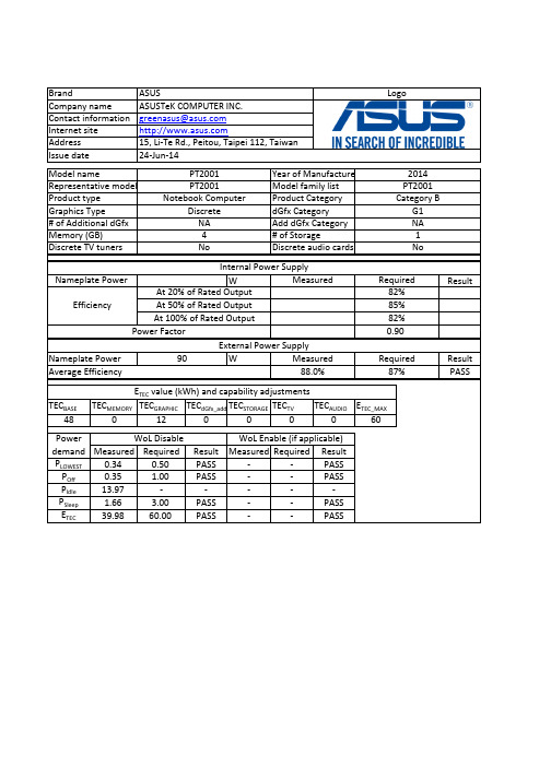
WResultW Result PASSTEC BASETEC MEMORY TEC GRAPHIC TEC dGfx_add TEC STORAGE TEC TVTEC AUDIO E TEC_MAX48012000060Measured Required ResultMeasured Required ResultP LOWEST 0.340.50PASS --PASSP Off 0.35 1.00PASS --PASSP Idle 13.97-----P Sleep 1.66 3.00PASS --PASSE TEC 39.9860.00PASS--PASS0.90Power FactorIssue date24-Jun-14Product Category 2014Representative model Model nameYear of Manufacture Notebook ComputerCategory BProduct type PT2001PT2001Model family list EfficiencyAt 20% of Rated Output 82%Graphics Type# of Additional dGfx Internal Power SupplyNameplate Power Measured Required Memory (GB)Discrete TV tunersG1NA Discrete audio cards15, Li-Te Rd., Peitou, Taipei 112, Taiwan PT2001BrandCompany name Contact information Internet site Address LogoASUSASUSTeK COMPUTER INC.******************Discrete NA 4NoPower demand E TEC value (kWh) and capability adjustmentsAverage Efficiency 88.0%87%External Power SupplyAt 50% of Rated Output 85%At 100% of Rated Output 82%1No dGfx Category Add dGfx Category # of StorageWoL DisableWoL Enable (if applicable)Nameplate Power 90Measured Required4. The power management feature is enabled by default.The measurement methodologyECMA-383, Measuring the Energy Consumption of Personal Computing ProductsThe instrumentation, set-up and circuits used for electrical testing are accordance with ECMA-383Test voltage in V and frequency in Hz Total harmonic distortion of the electricity supply system 230V, 50Hz <21. Power management is a process that allows displays and computers (CPU, hard drive, etc.) to enter low-power states when sitting idle.12. Users can adjust how long your computer waits before sleeping or hibernating. Please refer to the user manual or website of O.S. provider for further information.Can the battery[ies] in this notebook computer be easily replaced by users themselvesNO13. Lowest power state means the state with the lowest power demand found in a computer. This mode may be entered or left by either a mechanical means or via automatic means14. Idle state means a state of a computer in which the operating system and other software have completed loading, a user profile has been created, the computer is not in sleep mode, and activity is limited to those basic applications that the operating system starts by default 9. The computer is automatically set to sleep after 30 minutes of user inactivity.2. Inactive displays with enabled power management enter low-power modes by turning off monitor output, which can save $10 to $30(USD) per monitor annually3. The low power modes of inactive computers can involve reducing power consumption or spinning down the hard disk, which can save $15 to $45(USD) per desktop computer annually.10. To wake your computer, click the mouse, press power button, or press any key on the keyboard.11. For windows system, Notebook Computers will enter into hibernation after 360 minutes5. Sleep is a power-saving state that allows a computer to quickly resume full-power operation (typically within several seconds) when users want to start working again.6. Hibernation is a power-saving state designed primarily for laptops. Of all the power-saving states in Windows, hibernation uses the least amount of power.7. Hybrid sleep is designed primarily for desktop computers. Hybrid sleep is a combination of sleep and hibernate. When hybrid sleep is turned on, putting your computer into sleep automatically puts your computer into hybrid sleep. Hybrid sleep is typically turned on by default on desktop computers.the minimum number of loading cycles that the batteries can withstand 26.70300noise levels (the declared A-weighted sound power level)the total content of mercury as X,X mg of integrated displayNA 8. The display is automatically set to sleep after 10 minutes of user inactivity.。
PR2001资料

PR2001 - PR20052.0A FAST RECOVERY RECTIFIERFeaturesAAB CDDO-15Dim Min Max A 25.40¾B 5.507.62C 0.6860.889D2.603.6All Dimensions in mmMaximum Ratings and Electrical Characteristics@ T A = 25°C unless otherwise specified·Diffused Junction·Fast Switching for High Efficiency·High Current Capability and Low Forward Voltage Drop·Surge Overload Rating to 50A Peak ·Low Reverse Leakage Current ·Plastic Material: UL Flammability Classification Rating 94V-0Mechanical Data·Case: Molded Plastic·Terminals: Plated Leads Solderable per MIL-STD-202, Method 208·Polarity: Cathode Band ·Marking: Type Number·Weight: 0.4 grams (approx.)Single phase, half wave, 60Hz, resistive or inductive load.For capacitive load, derate current by 20%.CharacteristicSymbol PR 2001PR 2002PR 2003PR 2004PR 2005Unit Peak Repetitive Reverse Voltage Working Peak Reverse Voltage DC Blocking Voltage V RRM V RWM V R 50100200400600V RMS Reverse VoltageV R(RMS)3570140280420V Average Rectified Output Current (Note 1)@ T A = 50°C I O 2.0A Non-Repetitive Peak Forward Surge Current8.3ms Single half sine-wave Superimposed on Rated Load (JEDEC Method)I FSM 50A Forward Voltage@ I F = 2.0A V FM 1.2V Peak Reverse Current@ T A = 25°C at Rated DC Blocking Voltage @ T A = 100°CI RM 5.0100m AReverse Recovery Time (Note 3)t rr 150250ns Typical Junction Capacitance (Note 2)C j 3515pF Typical Thermal Resistance Junction to Ambient R q JA 50K/W Operating and Storage Temperature RangeT j,T STG-65 to +150°CNotes:1.Valid provided that leads are maintained at ambient temperature at a distance of 9.5mm from the case.2.Measured at 1.0MHz and applied reverse voltage of 4.0 V DC.3.Measured with I F = 0.5A, I R = 1.0A,I rr = 0.25A. See figure 5.I ,P E A K F O R W A R D S U R G E C U R R E N T (A )F S M 0204060110100NUMBER OF CYCLES AT 60Hz Fig.3Peak Forward SurgeCurrent110100110100C ,C A P A C I T A N C E (p F )j V ,REVERSE VOLTAGE (V)Fig.4Typical Junction CapacitanceR00.40.81.21.62.0255075100125150175200I ,A V E R A G E F W D R E C T I F I E D C U R R E N T (A )(A V )T ,AMBIENT TEMPERATURE (C)Fig.1Forward Derating Curve A °Set time base for 50/100ns/cm+0.5A0A -0.25A-1.0ANotes:1.Rise Time =7.0ns max.Input Impedance =1.0M ,22pF.2.Rise Time =10ns max.Input Impedance =50.ΩΩFig.5Reverse Recovery Time Characteristic and Test Circuit0.010.11.0100.60.8 1.0 1.2 1.4I ,I N S T A N T A N E O U S F W D C U R R E N T (A )F V ,INSTANTANEOUS FORWARD VOLTAGE (V)Fig.2Typical Forward CharacteristicsF。
2001 Honda Civic Sedan 用户手册说明书

2001 Civic Sedan Online Reference Owner's ManualUse these links (and links throughout this manual) to navigate through this reference.For a printed owner's manual, click on authorized manuals or go to .If you have a Civic GX refer to Civic Sedan GX Owner’s Manual Supplement for additional information.ContentsOwner's Identification Form Introduction (i)A Few Words About Safety (ii)Your Car at a Glance (2)Driver and Passenger Safety (5)Proper use and care of your car's seat belts, and Supplemental Restraint System.Instruments and Controls (57)Instrument panel indicator and gauge, and how to use dashboard and steering column controls.Comfort and Convenience Features (105)How to operate the climate control system, the audio system, and other convenience features.Before Driving (159)What gasoline to use, how to break-in your new car, and how to load luggage and other cargo. Driving (173)The proper way to start the engine, shift the transmission, and park, plus towing a trailer. Maintenance (191)The Maintenance Schedule shows you when you need to take your car to the dealer.Appearance Care (253)Tips on cleaning and protecting your car. Things to look for if your car ever needs body repairs.Taking Care of the Unexpected (261)This section covers several problems motorists sometimes experience, and how to handle them.Technical Information (289)ID numbers, dimensions, capacities, and technical information.Warranty and Customer Relations (U.S. and Canada) (303)A summary of the warranties covering your new Honda, and how to contact us.Authorized Manuals (U.S. only) (309)How to order manuals and other technical literature.Index (I)Service Information SummaryA summary of information you need when you pull up to the fuel pump.。
- 1、下载文档前请自行甄别文档内容的完整性,平台不提供额外的编辑、内容补充、找答案等附加服务。
- 2、"仅部分预览"的文档,不可在线预览部分如存在完整性等问题,可反馈申请退款(可完整预览的文档不适用该条件!)。
- 3、如文档侵犯您的权益,请联系客服反馈,我们会尽快为您处理(人工客服工作时间:9:00-18:30)。
Key Features:
• 20W Output Power • 4:1 Input Voltage Range • Compact 1 x 2 Inch Case • 1,600 VDC Isolation • High Effi ciency • Single & Dual Outputs • Remote ON/OFF
•
Industry Standard Pin-Out B2000RU 4:1 Input Range, 20W Single & Dual Output DC/DC Con v ert e rs
Series
MicroPower Direct
292 Page Street Suite D
Stoughton, MA 02072USA
T: (781) 344-8226F: (781) 344-8481
E: sales@ W:
Electrical Specifi cations
Specifi cations typical @ +25°C, nominal input voltage & rated output current, unless otherwise noted. Specifi cations subject to change without notice.
Notes:
1. Transient recovery is measured to within a 1% error band for a load step change of 75% to 50% to 25%.
2. Operation at no-load will not damage these units. However, they may not meet all specifi cations.
3. Dual output units may be connected to provide a 10 VDC, 24 VDC or 30 VDC output. To do this, connect the load across the positive (+Vout) and negative (-Vout) outputs and fl oat the output common.
4. It is recommended that a fuse be used on the input of a power supply for protection. See the table above for the correct rating.
To help meet EN55022 conducted emissions requirements, a simple Pi fi lter should be added externally to the input of the converter. Recommended components (C 1, C 2 & L 1) are shown in the diagram above.These compo-nents should be mounted as close to the module as possible.
To meet the requiremets of EN61000-4-4, EN61000-4-5 and EN61000-4-6, an external capacitor is required. It is recommended that the value shown in the fi gure above (C 3) be used.
When measuring output ripple, it is recommended that an external 1.0 µF ceramic capacitor be placed from the +Vout pin to the -Vout pin for single output units and from each output to common for dual output units. For noise sensitive applications, the use of 3.3 µF capacitors (as shown in the diagram above) will reduce the output ripple.
A positive logic Remote On/Off input (Pin 6) can be used
to control the converter. An open collector (or open drain) switch (Q 1) is placed between the control input (Pin 6) and the -V Input (Pin 2).
If not being used, the control input should be left open.
Model Selection Guide
Recommended Input/Output Components
Page 2 Web: • Email: sales@ • Tel: (781) 344 - 8226 • Fax: (781) 344 - 8481
Series
B2000RU
A simple external circuit may be used to adjust Vout on single output models. To adjust the output DOWN, con-nect a 5%, 3W resistor between the plus output pin and the Vout trim pin. To adjust the output UP , connect a 5%, 3W resistor between the minus output pin and the Vout trim pin. Resistor values are given in the chart below. For UP/Down trimming capability, connect a 10 kW poten-tiometer between the plus and minus outputs with the wiper arm connected to the Vout trim pin.
Care should be taken that the maximum output power of the unit does not exceed the maximum rating.
Output Trim (Single Output Models)
MicroPower
Direct
Web: • Email: sales@ • Tel: (781) 344 - 8226 • Fax: (781) 344 - 8481
Page 3
MicroPower Direct
292 Page Street Ste D Stoughton, MA 02072 • TEL: (781) 344-8226 • FAX: (781) 344-8481 • E-Mail: sales@
Mechanical Dimensions
Mechanical Notes:
• All dimensions are typical in inch e s (mm)
•
Tolerance x.xx = ±0.01 (±0.25)
Derating Curve。