HLMP-CW23-SV0xx中文资料
HP Pavilion 23cw IPS LED Backlit Monitor 说明书

HP Pavilion 23cw 23-inch IPSLED Backlit MonitorStreamlined colorful brillianceExperience amazing imagery at aprice within reach. Share thespectacular viewing angles andstunning Full-HD resolution,radiating from the streamlined HPPavilion 23cw IPS LED BacklitMonitor.(1)Product overview•Amazing angles: Share consistent high-color fidelity with In-Plane Switching (IPS) technology across a 23-inch diagonal screen. A stunning vantage point for everyone, from almost any angle.•Distinctively modern and accessible: The contemporary thin profile is enhanced by the modern black and silver colors.The open WEDGE stand design provides convenient access to VGA and dual HDMI ports. •Captivating imagery: Color and clarity radiate from the screen with Full HD 1920 x 1080 resolution(1), incredible 5,000,000:1 dynamic contrast ratio, 16:9 aspect ratio, and quick 7 ms response time.(2)Key specifications•Viewable image area: 23-inch diagonally measured•Panel: Anti-glare•Contrast: 5,000,000:1 Dynamic Contrast Ratio(2)•Resolution: 1920 x 1080 @ 60 Hz (Full HD)•HDMI: 2 ports•VGA: 1 port•Response time: 7ms(2)•Exterior color: Jet Black and Natural Silver Product features•Frameless display: Bezel-less design creates a larger viewing experience.•Reduce the reflection: The anti-glare treatment reduces glare and reflection.•Versatile viewing: Easily adjust your view by tilting 2° forward to 25° backward.•Enhanced visuals: HP Enhance+ improves image quality with advanced noise reduction.(3)•User control OSD settings: User-preferred settings can be saved with the HP My Display software.•Quick response: Response Time - 7ms GtG with overdrive•Simple button control: Subtle buttons underneath display provide convenient screen, menu and power control.•Color: Certified by Technicolor(10)Environmentally conscious•Mercury-free LED backlighting•Arsenic-free display glass•Low halogen design(5)•Recyclable components and packaging(8)•Energy Star® 6.0•EPEAT® Silver rating(7)Peace of mind coverageRest easy and work confidently with an HP standard 1 year limited warranty. Certain restrictions and exclusions apply.(9)HP Pavilion 23cw 23-inch IPS LED Backlit MonitorHD (High Definition) content required to view HD images. All performance specifications represent the typical specifications provided by HP's component manufacturers; actual performance may vary either higher or lower. Results may vary based on the viewing quality of the original image (picture, photo or video) and the difference between the monitor’s previous settings compared to the new HP Enhance+ mode. Standard parts-and-labor hardware 1-year warranty. Contact HP Consumer Support 24x7 at 800-334-5144 US for HP technical phone support during the warranty period. See /go/support for details. Plastic parts incorporated into the chassis generally contain < 1000 ppm (0.1%) of bromine or chlorine. Printed circuit board and substrate laminates generally contain < 1500 ppm (0.15%) of total bromine and chlorine. Service parts after purchase may not be BFR/PVC-free. External accessories, including power supplies, power cords, and peripherals are not BFR/PVC-free. Arsenic and its compounds were not detected using U.S. EPA test methods 3052/6010b by ICP-AES with a Method Detection Limit of 10 ppm. Low-halogen except for adapter and cord. EPEAT® Silver where HP registers consumer display products. See for registration status in your country. Free recycling in select countries. Program may not be available in your area. Check /go/recycling to see if HP offers free recycling in your area. Standard parts-and-labor hardware 1-year warranty. Contact HP Consumer Support 24x7 at 800-334-5144 US for HP technical phone support during the warranty period. See /go/support for details. TCO Certification administered by TCO Development, owned by the Swedish Confederation of Professional Employees.Actual product may vary from image shown on datasheet. ©Copyright 2015 Hewlett-Packard Development Company, L.P. The information contained herein is subject to change without notice. The only warranties for HP products and services are set forth in the express warranty statements accompanying such products and services. Nothing herein should be construed as constituting an additional warranty. HP shall not be liable for technical or editorial errors or omissions contained herein. ENERGY STAR and the ENERGY STAR mark are registered trademarks owned by the U.S. Environmental Protection Agency. 02/04_r1 tgLearn more at Monitor SpecificationsPanel Type •23-inch diagonal IPS with LED Backlight Panel Active Area•509.184mm x 286.416mmViewable image area •23-inch diagonally measured Viewing angle •Horizontal: 178° •Vertical: 178° Anti-Glare Panel •YesNative Resolution (recommended)•1920 x 1080 @ 60 Hz (Full HD)Contrast Ratio •Static: 1,000:1•Dynamic: 5,000,000:1(2)Brightness (typical)•250 nits Color Gamut •72% Pixel Pitch •0.265mm •96 PPIResponse Time (typical)•7ms gray to gray (2)Signal Input Connectors • 1 VGA • 2 HDMI•HDCP supportPower Supply •External power supply, 100 to 240 VAC Maximum Power Consumption •27W Energy Saving Mode •<0.5WTilt•-2 to + 25 degrees Detachable Base •YesUnpackaged Dimensions •20.94 in x 5.94 in x 15.87 in Unpackaged Weight•9.24 lbPackaged Dimensions •23.94 in x 5.12 in x 16.54 in Packaged Weight •14.7 lbLanguages•German, Simplified Chinese, Traditional Chinese,Japanese, English, Spanish, French, Italian, Netherlands, Brazilian Portuguese Certifications•Microsoft WHQL Certification (Windows 8.1 and Windows 7)•Technicolor Certified (10)Software•HP My Display software: Partition screen for multiple windows.On Screen Display•Display features: Brightness, Contrast, Color, Image Control, OSD control, Management, Language, Information, Factory Reset, Input Control User controls •User programmable modes: 10•Monitor Control Buttons:-Main Menu, Next or Enter, Select/OK-Brightness, Minus/Down, Quick View Menu -AUTO, Plus/Up, Quick View -Next Input, Back/Cancel/Exit -PowerEnvironmental FeaturesLED Backlights •Mercury-freeArsenic-Free •Arsenic-free display glass Low Halogen •Yes (5)Certifications•ENERGY STAR® 6.0 certified •EPEAT® Silver registered (7)Accessories & WarrantySupplied Accessories •AC power cable •Power adapter •VGA cable•CD (User guide, warranty, drivers)•Quick Setup posterLimited Warranty•Protected by an HP standard one-year limited warranty. Certain restrictions and exclusions apply.Additional InformationProduct Number •J7Y74AA#ABA Ad Embargo Date •04/19/2015UPC Code •888793389478Country of Origin •China Tariff Number•852*******Pallet Information•Dimensions: 48.0 in x 40.0 in x 86.5 in •Total weight: 929.5 lb •Layers: 5•Products per layer: 14•Total products per pallet: 70。
丹佛斯产品册中文
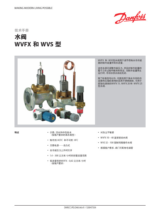
MAKING MODERN LIVING POSSIBLE特点y y介质:淡水和中性盐水(按客户要求的海水类型)yy y制冷剂:HCFC y和不可燃y HFC yy y无需电源——自力式yy y在冷凝压力上升时打开yy 1.4 – 300 立方米/小时的完整流量范围yy y低流量型的WVFX – 0,63 立方米/小时y(按客户要求)yy y对灰尘不敏感yy WVFX 10 – 40 直接驱动水阀yy WVS 32 – 100 强制伺服操作水阀y y y根据客户需求,阀门可配有毛细管技术手册水阀WVFX 和 WVS 型WVFX y和y WVS型水阀用于调节带有水冷冷凝器的制冷装置中的水流量。
这些水阀可调整冷凝压力,并且在制冷装置的整个工作过程中维持其恒定。
当制冷装置停止运行时,冷却水供水自动关闭。
除了标准型号以外,可提供用于海水冷却的冷凝器和压缩机使用的采用不锈钢阀体,可用于腐蚀性液体的WVFX 15、WVFX 20 和y WVFX 25型水阀。
参数表 水阀,WVFX 和 WVS 型技术参数1) k v值为水在通过阀的压差等于 1 bar时的流量,单位为[立方米/小时],密度ρ = 1000 千克/立方米。
2)完全打开阀则需要比使用压力范围为 3.5-16 bar的WVFX阀压力高y33%y的压力,3) WVFX 15、WVFX 20 和y WVFX 25型水阀可提供不锈钢阀体。
WVFX 10 – 40 为直接驱动调节阀yWVS 32 – 100 为伺服操作调节阀介质温度范围yWVFX 10 – 25: -25 – 130 °C yWVFX y32 – 40: -25 – 90 °C yWVS:y y-25 – 90 °C y如果一个WVS型调节器需要 1 - 10 bar y的开启压力差时,y必须更换阀的伺服弹簧。
见“订货”部分。
开启压力差yWVFX 10 – 25:yy最大 10 bar y WVFX 32 – 40:yy最大 10 bar y WVS 32 – 40:yy最小 0.5 bar:y y最大 4 bar y WVS 50 – 100:yy最小 0.3 bar;y y最大 4 bar y低于最大负荷的 20% 时,WVSy实际上将作为一个开关调节器。
海道夫 旋转蒸发仪 信息

• 蒸发瓶的倾斜角度可以在20度到80度范围内快速调整
持续经济效益-可衡量的高效率
• 节省处理时间取决于您所选的型号,最高可达30% • 耐化学腐蚀的真空密封设备使用寿命长,让您减少
高达75%的费用支出 • 长使用寿命的蒸汽管同样让您节省费用 • 使用5L蒸发瓶,增加各种应用范围而无其他费用增加
配件费用
• 冷凝器一侧的密封圈和夹子是PPS材质(聚 苯硫醚),优越的工业设计比不锈钢或合成 铝具有 更优异的耐化学腐蚀性,使冷凝水和 腐蚀性试剂对仪器的损害降低到最小程度,节 省了额外维修和更换部件的费用
• Hei-VAP加热锅温度达210°C,比市场其他 旋转蒸发仪最高温度高30°C,应用更为广 泛,从而减少在其他各种应用设备的投资
套装 Page 22-23
制冷器 Pag e 24-25 制冷器Pa
3
Hei-V AP系列 - 模块化概念设计
Hei-VAP 产品系列
选配的遥控操作面板可让您 监控旋转蒸发仪的进程数据, 让您的工作更灵活。
蒸汽管容易装卸,是延长使用 寿命的专利。
简易卸除蒸汽管, 简化您的工作。
长使用寿命从而减少75%的 额外更换费用。
高安全性: 由于Hei-VAP 蒸汽管不再被固定于 马达上,避免打碎玻璃组件。
Hei-VAP Series 4 5
- 乙醇
- 水 冷凝 面积
(cm2)
电压*** (V/Hz)
* ∆T = 不同的加热温度和沸腾温度 ** 需结合真空系统使用
155 20 - 280
刻度
1300 20 - 210
± 1
刻度 电子/数字
250 V4A (1.4404)
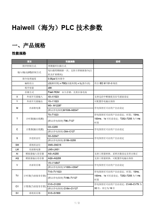
Haiwell(海为)PLC技术参数
输入通道 1 的输入值 通道 1 的输入值
通道 1 的输入值
通道 2 的输入值
通道 3 的输入值
通道 4 的输入值
通道 1 的信号类 型,备注 2 通道 2 的信号类 型,同上 通道 3 的信号类 型,同上 通道 4 的信号类 型,同上 使用工程量标志, 备注 6 通道 1 的工程量下 限值 通道 2 的工程量下 限值 通道 3 的工程量下 限值 通道 4 的工程量下 限值 通道 1 的工程量上 限值
程序容量
48K
存储方式
Flash ROM 永久存储,无需后备电池
X
外部开关量输入 X0~X1023
支持边沿中断捕捉及信号滤波设定
Y
外部开关量输出 Y0~Y1023
可配置停电输出保持
M0~ M12287
M
内部继电器
(默认停电保持)M1536~M2047
停电保持区可由用户自由设定
T0~T1023
T
计时器(输出线圈)
停电保持区可由用户自由设定
SM
系统状态位
SM0~SM215
LM
局部继电器
LM0~LM31
AI
模拟量输入寄存器 AI0~AI255
支持工程量转换、采样次数设定及零点修正
AQ
模拟量输出寄存器 AQ0~AQ255
V0~V14847
V
内部寄存器
(默认停电保持) V1000~V2047
TV0~TV1023 TV 计时器(当前值寄存器)
-10V~+10V 5mV
电压输入
0V~+10V 0V~+5V
2.5mV
1.25mV
1V~+5V 1.25mV
麦克维尔产品手册

10101010101010101010101010101010101010101010101010101010101010101010101001010101010101010101010101010101010100101010101010101010101010101010101010101010101010101010101010101010101010101010101010101010101010101010101010010101010101010101010101010101010101001010101010101010101010101010101010101010101010101010101010101010101010101010101010101001010101010101010101010101010101010100101010
E3612/C3612 E3612/C3012 E3612/C3012 E3612/C3012 E3612/C3612 E4212/C3612 E4212/C3612 E4212/C3612 E4212/C3612 E4212/C3612 E4212/C4212 E4812/C4812
制冷量
RT
750
型号
WSC WDC WSC(H) WDC(H) WMC HSC PFS PFS XE PES WMD WHS.B HHS.B CUW CUW-HR CUWD-HR CUWD CUWD-HC WGZ-B
制冷量
制冷剂
300RT〜1300RT
HFC-134a
600RT〜2560RT 600RT〜1200RT 1200RT〜2300RT 140RT〜287RT
HLMP-C517-X0000中文资料
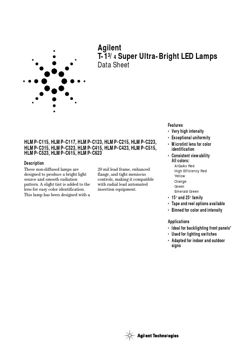
DescriptionThese non-diffused lamps are designed to produce a bright light source and smooth radiationpattern. A slight tint is added to the lens for easy color identification.This lamp has been designed with aHLMP-C115, HLMP-C117, HLMP-C123, HLMP-C215, HLMP-C223,HLMP-C315, HLMP-C323, HLMP-C415, HLMP-C423, HLMP-C515,HLMP-C523, HLMP-C615, HLMP-C623Features•Very high intensity •Exceptional uniformity •Microtint lens for color identification•Consistent viewability All colors: AlGaAs RedHigh Efficiency Red Yellow Orange GreenEmerald Green •15° and 25° family•Tape and reel options available •Binned for color and intensity Applications•Ideal for backlighting front panels*•Used for lighting switches •Adapted for indoor and outdoor signsAgilentT-13/4 Super Ultra-Bright LED LampsData Sheet20mil lead frame, enhanced flange, and tight meniscus controls, making it compatible with radial lead automated insertion equipment.Selection GuidePart Number Luminous Intensity Iv (mcd) Color2θ1/2[1]Standoff Leads HLMP-Min.Max.DH AS AlGaAs15No C115290.0–C115-O00xx290.0–C115-OP0xx290.01000.0Yes C117-OP0xx290.01000.025No C12390.2–C123-L00xx90.2–Red15No C215138.0–C215-M00xx138.0–C215-MN0xx138.0400.025No C22390.2–C223-L00xx90.2–C223-MN0xx138.0400.0 Yellow15No C315147.0–C315-L00xx147.0–C315-LM0xx147.0424.025No C32396.2–C323-K00xx96.2–C323-KL0xx96.2294.0 Orange15No C415138.0–C415-M00xx138.0–C415-M0D0xx138.0–C415-MN0xx138.0400.025No C42390.2–C423-L00xx90.2–C423-LM0xx90.2276.0 Green15No C515170.0–C515-L00xx170.0C515-LM0xx170.0490.025No C52369.8–C523-J00xx69.8–C523-KL0xx111.7340.0 Emerald Green15No C61517.0–C615-G00xx17.0–25No C623 6.7–C623-E00xx 6.7–Part Numbering SystemHLMP - C x xx - x x x xxMechanical Options00: Bulk01: Tape & Reel, Crimped Leads02: Tape & Reel, Straight LeadsB2: Right Angle Housing, Even LeadsUQ: Ammo Pack, Horizontal LeadsColor Bin Options0: Full Color Bin DistributionD: Color Bins 4 & 5 onlyMaximum Iv Bin Options0: Open (No Maximum Limit)Others: Please refer to the Iv Bin TableMinimum Iv Bin OptionsPlease refer to the Iv Bin TableViewing Angle & Standoffs Options15: 15 Degree, without Standoffs17: 15 Degree, with Standoffs23: 25 Degree, without StandoffsColor Options1. AS AlGaAs Red2. High Efficiency Red3. Yellow4. Orange5. Green6. Emerald GreenPackage OptionsC: T-1 3/4 (5 mm)Absolute Maximum Ratings at T A = 25°CHighHighDH AS Efficiency Performance AlGaAs Red and Green and ParameterRed Orange Yellow Emerald Green Units DC Forward Current [1]30302030mA Transient Forward Current [2]500500500500mA (10 µsec Pulse)Reverse Voltage (Ir = 100 µA)5555V LED Junction Temperature 110110110110°C Operating Temperature Range –20 to +100–55 to +100–20 to +100°C Storage Temperature Range –55 to +100°CWave Soldering Temperature 250°C for 3 seconds [1.59 mm (0.063 in.) from body]Lead Solder Dipping Temperature 260°C for 5 seconds[1.59 mm (0.063 in.) from body]Notes:1. See Figure 5 for maximum current derating vs. ambient temperature.2. The transient current is the maximum nonrecurring peak current the device can withstand without damaging the LED die and wire bond.Package DimensionsHLMP-Cx15 and HLMP-Cx23HLMP-Cx17(0.039)NOTES:1. ALL DIMENSIONS ARE IN MILLIMETERS (INCHES).2. LEADS ARE MILD STEEL, SOLDER DIPPED.3. AN EPOXY MENISCUS MAY EXTEND ABOUT 0.5 mm (0.020 in.) DOWN THE LEADS.± 0.20± 0.008)Electrical Characteristics at T A = 25°CForward Reverse Capacitance Speed of ResponseVoltage Breakdown C (pF)Thermalτs (ns)Vf (Volts)Vr (Volts)Vf = 0Resistance Time Constant@ If = 20 mA@ Ir = 100 µA f = 1 MHz RθJ-PIN e-t/τsPart Number Typ.Max.Min.Typ.(°C/W)Typ.HLMP-C115 1.8 2.253021030HLMP-C117HLMP-C123HLMP-C215 1.9 2.651121090HLMP-C223HLMP-C315 2.1 2.651521090HLMP-C323HLMP-C415 1.9 2.654210280HLMP-C423HLMP-C515 2.2 3.0518210260HLMP-C523HLMP-C615 2.2 3.0518210260HLMP-C623Optical Characteristics at T A = 25°CLuminous Color,ViewingIntensity Peak Dominant Angle LuminousIv (mcd)Wavelength Wavelength2θ1/2Efficacy@ 20 mA[1]λpeak (nm)λd[2] (nm)(Degrees)[3]ηvPart Number Min.Typ.Typ.Typ.Typ.(lm/w) HLMP-C1152906006456371180HLMP-C117HLMP-C1239020026HLMP-C215138300635626171459017023HLMP-C315146300583585175009617025HLMP-C415138300600602173809017023HLMP-C515170300568570205956917028HLMP-C61517455585602065662728Notes:1. The luminous intensity, Iv, is measured at the mechanical axis of the lamp package. The actual peak of the spatial radiation pattern may not bealigned with this axis.2. The dominant wavelength, λd, is derived from the CIE Chromaticity Diagram and represents the color of the device.3. 2θ1/2 is the off-axis angle where the luminous intensity is 1/2 the on-axis intensity.Figure 1. Relative intensity vs. wavelength.Figure 2. Forward current vs. forward voltage (non-resistor lamp).Figure 3. Relative luminous intensity vs. forward current.WAVELENGTH – nmR E L A T I V E I N T E N S I T Y1.00.50I F – F O R W A R DC U R R E N T – m AV F – FORWARD VOLTAGE – VI F – F O R W A R D C U R R E N T – m AV F – FORWARD VOLTAGE – VHIGH EFFICIENCY RED, ORANGE,YELLOW, AND HIGH PERFORMANCEGREEN, EMERALD GREENR E L A T I V E L U M I N O U S I N TE N S I T Y (N O R M A L I Z E D A T 20 m A )I F – DC FORWARD CURRENT – mA R E L A T I V E L U M I N O U S I N T E N S I T Y (N O R M A L I Z E D A T 20 m A )0I DC – DC CURRENT PER LED – mA10201.60.80.4515301.2250.20.61.01.4HER, ORANGE, YELLOW, AND HIGH PERFORMANCE GREEN, EMERALD GREENFigure 5. Maximum forward dc current vs. ambient temperature. Derating based on T j MAX = 110°C.Figure 4. Relative efficiency (luminous intensity per unit current) vs. peak current.Figure 6. Relative luminous intensity vs. angular displacement. 15 degree family.R E L A T I V E E F F I C I E N C Y (N O R M A L I Z E D A T 20 m A )0I PEAK – PEAK FORWARD CURRENT – mA0.60.8300201001.21.00.20.45020010DH As AlGaAs REDηP E A K – R E L A T I V E E F F I C I E N C Y (N O R M A L I Z E D A T 20 m A )I PEAK – PEAK FORWARD CURRENT – mAHER, ORANGE, YELLOW, HIGHPERFORMANCE GREEN, EMERALD GREENI F – F O R W A R D C U R R E NT – m AT A – AMBIENT TEMPERATURE – °C DH As AlGaAs REDI F – F O R W A R D C U R R E N T – m AT A – AMBIENT TEMPERATURE – °CHER, ORANGE, YELLOW, AND HIGH PERFORMANCE GREEN, EMERALD GREEN N O R M A L I Z E D L U M I N O U S I N T E N S I T Y10ANGULAR DISPLACEMENT – DEGREES0.80.60.50.70.2450.10.30.4403530252010515-5-10-15-20-25-30-35-40-450.9Figure 7. Relative luminous intensity vs. angular displacement. 25 degree family.Intensity Bin Limits Intensity Range (mcd)ColorBin Min.Max.L 101.5162.4M 162.4234.6N 234.6340.0O 340.0540.0P 540.0850.0Q 850.01200.0R 1200.01700.0Red/OrangeS 1700.02400.0T 2400.03400.0U 3400.04900.0V 4900.07100.0W 7100.010200.0X 10200.014800.0Y 14800.021400.0Z 21400.030900.0L 173.2250.0M 250.0360.0N 360.0510.0O 510.0800.0P 800.01250.0YellowQ 1250.01800.0R 1800.02900.0S 2900.04700.0T 4700.07200.0U 7200.011700.0V 11700.018000.0W18000.027000.0N O R M A L I Z E D L U M I N O U S I N T E N S I T Y10ANGULAR DISPLACEMENT – DEGREES0.80.60.50.70.2450.10.30.4403530252010515-5-10-15-20-25-30-35-40-450.9Intensity Bin Limits, continuedIntensity Range (mcd) Color Bin Min.Max.E7.612.0F12.019.1G19.130.7H30.749.1I49.178.5J78.5125.7K125.7201.1L201.1289.0 Green/M289.0417.0 Emerald Green N417.0680.0O680.01100.0P1100.01800.0Q1800.02700.0R2700.04300.0S4300.06800.0T6800.010800.0U10800.016000.0V16000.025000.0W25000.040000.0 Maximum tolerance for each bin limit is ± 18%.Color CategoriesLambda (nm)Color Category #Min.Max.6561.5564.55564.5567.5 Green4567.5570.53570.5573.52573.5576.51582.0584.53584.5587.0 Yellow2587.0589.54589.5592.05592.0593.01597.0599.52599.5602.03602.0604.5 Orange4604.5607.55607.5610.56610.5613.57613.5616.58616.5619.5 Tolerance for each bin limit is ± 0.5 nm.Mechanical Option MatrixMechanical Option Code Definition00Bulk Packaging, minimum increment 500 pcs/bag01Tape & Reel, crimped leads, minimum increment 1300 pcs/bag02Tape & Reel, straight leads, minimum increment 1300 pcs/bagB2Right Angle Housing, even leads, minimum increment 500 pcs/bagUQ Ammo Pack, horizontal leads, in 1K minimum incrementNote:All categories are established for classification of products. Products may not be available in all categories. Please contact your local Agilent representative for further clarification/information./semiconductorsFor product information and a complete list ofdistributors, please go to our web site.For technical assistance call:Americas/Canada: +1 (800) 235-0312 or(916) 788-6763Europe: +49 (0) 6441 92460China: 10800 650 0017Hong Kong: (+65) 6756 2394India, Australia, New Zealand: (+65) 6755 1939Japan: (+81 3) 3335-8152 (Domestic/Interna-tional), or 0120-61-1280 (Domestic Only)Korea: (+65) 6755 1989Singapore, Malaysia, Vietnam, Thailand,Philippines, Indonesia: (+65) 6755 2044Taiwan: (+65) 6755 1843Data subject to change.Copyright © 2004 Agilent Technologies, Inc.Obsoletes 5965-6165ENovember 11, 20045988-2149EN。
德国哈威HAWE参数技术资料

德国哈威HAWE参数技术资料HAWE R系列哈威径向柱塞泵产品介绍: R型径向柱塞泵是由阀配式星形排列的柱塞缸组成。
通过多达6排柱塞缸的并联配置,可以实现较大的流量输出。
一般情况下,电机驱动泵,并通过法兰和联轴器与泵联接。
特别令人感兴趣的是该泵可派生多个压力输出口。
zui大压力Pmax=700bar zui大流量Qmax=91.2l/min德国HAWE哈威LP型液压泵工作气容量Vmax geom.=28,3 ml/双冲程输出流量Qmax液=approx.12 lpm工作压力Pmax液=1500 bar Pmax气=10 bar可与各种规格的油箱组成液压泵站,此泵站也可与换向阀组合德国HAWE哈威LP型液压泵的种类:1、按流量是否可调节可分为:变量泵和定量泵。
输出流量可以根据需要来调节的称为变量泵,流量不能调节的称为定量泵。
2、按液压系统中常用的泵结构分为:齿轮泵、叶片泵和柱塞泵3种。
齿轮泵:体积较小,结构较简单,对油的清洁度要求不严,价格较便宜;但泵轴受不平衡力,磨损严重,泄漏较大。
叶片泵:分为双作用叶片泵和单作用叶片泵。
这种泵流量均匀、运转平稳、噪音小、作压力和容积效率比齿轮泵高、结构比齿轮泵复杂。
德国哈威V30Z型轴向变量柱塞泵结构特征工作压力pmax=420bar排量vmax=2x115cm3/u.zui小的功率重量比.通过减轻变量机构重量,获得很短的调节时间.特殊的斜盘轴承,显著降低了噪音.全钢质柱塞套置于摇摆滑动圆盘的新型卸压支承结构,提高了典型磨损件的寿命..抗磨钢制造的控制盘结构设计,可降低柱塞腔内升压与减压产生的噪音德国哈威V30Z型轴向变量柱塞泵重要的优点.低的声压电平,因而在很多情况不必采取降噪的辅助措施.控制组件采用模块化结构,在装配与拆卸,以及改装控制部件时,不用拆开泵本体.机械式转角指示,是重要的功能控制辅助机构.通轴式驱动轴,便于组装各种符合ASE-A法兰标准的辅助泵HAWE哈威径向柱塞泵分为阀配流与轴配流两大类。
CWP_WROH中文操作手册

LOCAL 和 REMOTE ........................................................................2:11
HZCS12139 修订于 2004 年 11 月
序言
CE 标志 依据欧洲共同体委员会于 1993 年 6 月 14 日对医疗设备所发布的 93/42/EEC 指令的要求,本产品符合 CE 认证。 认证机构为:英国标准机构 (BSI),认证号为 0086。 以下标志为:制造年份。
本手册的 CE 标志只有在此产品经过 CE 认证后才有效。 生产厂家: Gambro Lundia AB,设备部门, Box 10101, SE-220 10 LUND,瑞典。 电话 +46 46 16 90 00。
微生物学指标 ...................................................................................... 1:4 化学质量.............................................................................................. 1:4
在 LOCAL/MAN 模式下运行 .............................................................2:7
正常启动.............................................................................................. 2:7 停止运行.............................................................................................. 2:7 启动热水循环 ...................................................................................... 2:7
Edwards mXDS3和mXDS3s干燥滚动吸力机产品介绍说明书
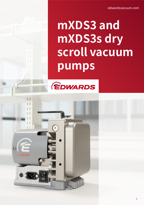
mXDS3 and mXDS3s dry scroll vacuum pumpsFILLING THE PERFORMANCE GAPEdwards mXDS3 and mXDS3s Small Dry Scroll Vacuum PumpsExtending the Edwards small dry pump portfolio.mXDS3 continues our scroll pump experience filling the performance gap and giving more choice to System builders and OEMs. A small dry alternative to oil sealed rotary vane pumps and diaphragm pumps of a similar capacity. mXDS3 are offered as standard or configured with an inlet valve accessory and exhaust silencer/filter to become the mXDS3s.The compact and lightweight mXDS3 weighs in at just 7.8kg and comes with a purpose made carry handle making it highly portable. For system builders the pump can typically be mounted horizontally or vertically and for convenient connection the inlet can be orientated vertically or horizontally with a push fit alternative available as an accessory.Edwards mXDS3 and mXDS3s dry scroll pumps deliver 3m3h-1peak speed and 0.1mbar ultimate. The pumping speed and good ultimate vacuum make these pumps well suited for backing turbomolecular pumps. These small scroll pumps have a gas ballast facility incorporated in the design as standard for water vapour handling and an exhaust valve just like the larger nXDS. Edwards mXDS3 and mXDS3s are clean oil free pumps with no oil to top up, replace or dispose of. They typically have a lower power requirement compared to similar capacity pumps making them great for energy savings, an ideal choice for helping to reduce your carbon footprint. The optimised fan cooling is beneficial in reducing noise for quieter operation and a pleasant working environment.Flexibility Performance EnvironmentScientific Instruments andOEMsResearch and DevelopmentSmall System BuildersOccupies minimal footprint saving valuable space in your environment. Highly portable vacuum pump with carry handle making it easy to move and position. Standard pump weighs in at just 7.8kg.FlexibilityCompact and LightweightPump can typically be mounted horizontally but can also be mounted vertically, giving flexibility to the system builder. Brackets and baseplate can also enable vibration isolators to be fitted.FlexibilityMounting optionsfor convenient connection a push fitalternative is available along with a wide range of other accessories.FlexibilityInlet can be orientated vertically or horizontallywith a pumping speed of 3m 3h -1and a good ultimate vacuum 0.1mbar makes these pumps well suited for backing turbomolecular pumps.PerformanceExcellent performanceas standard for water vapour handling.PerformanceGas ballast incorporatedas standard just like the larger nXDS in the family, this acts to reduce the rate of pressure rise at the inlet for system protection.PerformanceExhaust valve includedfully configured variant supplied withfactory fitted delay opening inlet valve and exhaust silencer/filter accessory.PerformancemXDS3sclean and dry with a typically lower power requirement compared to similar capacity pumps making for good energy savings and the opportunity to reduce your carbon footprint. With optimised fan cooling for quiet operation making a more pleasant working environment.EnvironmentEnvironmentally friendlyCompact air cooled motorSelect appropriate motor variant for local electric supplyPlug in IEC power cableOn/off switch for local control Easy to set up and runDN 16-KF flange can face up or to the back of the pump for compact installation.An alternative inlet with 1/4 inch BSP connection available as an accessory which can be used withsuitable push fit fittings1. Mains driven motor2. InletAssists with water vapour pumping and clean up 1/8 inch BSP adaptors and restrictors offered as accessories1/8 inch BSP push in fitting supplied as standard suitable for 8mm od hose.Silencer supplied with configured pumpPick up and place pumpSupplied as standard mXDS3s only. Fast closing in the event of power failure, this inlet valve provides extra system protection especially if using gas ballast.Delay opening on startup ensures the pump is evacuated when the inlet valve opensBase plate and bracket accessories available.Flexibility in orientation, optimising spaceutilisation and the option to fit vibration isolators3. Gas ballast4. Exhaust5. Carry handle6. Solenoid inlet valve with delayopening relay7. Base mounting or face mounting11Ultimate vacuum with closed gas ballast mbar 0.1Ultimate vacuum with gas ballast (1 turn)mbar 0.15Peak pumping speed (50Hz)m 3h-13Peak pumping speed (60Hz)m 3h-13.5Maximum permitted inlet pressure*mbar 1000Typical initial pressure rise on power loss (no inlet valve, with no inlet or gas ballast flow)mbar l5*These pumps are designed to pump down from atmospheric pressure, but prolonged operation at high inlet pressures may reduce bearing life.* These pumps are intended to exhaust to atmospheric pressure. High exhaust pressure may reduce tip-seal life.* Large volumes may be pumped, but prolonged operation at high inlet pressures may reduce bearing life.Supply voltageV100 +/- 6% 1 phase 115 +/- 10% 1 phase200 +/- 10% 1 phase 230 +/- 10% 1 phaseSupply frequencyHz 50/60Power consumption at ultimate W180210Mains connectorIEC EN60320 C13Weightkg 7.88Inlet connection DN 16 ISO-KFOutlet connectioninch 1/8 BSP for 6x8mm hose 1/8 BSP for 6x8mm hose exhaust filter suppliedVACUUM DATAMOTOR DATAPHYSICAL DATAmXDS3 and mXDS3s (3601 0743 01)PHYSICAL DATANoise level at ultimate vacuum dB (A)54.0 ±2.5Vibration measured at plane of bearing mms-1Class 1C…<4.5 (rms radial)Leak tightness mbar/ls-11x10-4Overall dimensions (L x W x H)mm224 x 158 x 231Nominal rotational speed Hz3000 rpm @ 50 / 3600 rpm @ 60Ambient temperature range (operation)°C+5 to +4013mXDS3 and mXDS3s (3601 0743 01)PRODUCTSmXDS3 230V 1ph 50/60Hz A74401903High Volts 230VmXDS3s 230V 1ph 50/60Hz A74402903mXDS3 200V 1 ph 50/60Hz A74401904High Volts 200VmXDS3s 200V 1ph 50/60Hz A74402904mXDS3 115V 1ph 50/60Hz A74401906Low Volts 115VmXDS3s 115V 1ph 50/60Hz A74402906mXDS3 100V 1ph 50/60Hz A74401907Low Volts 100VmXDS3s 100V 1ph 50/60Hz A74402907 ACCESSORIESInlet valve 100 - 120V A74402920Inlet valve 200 - 240V A74402921Delay relay A74402922Gas ballast or exhaust push-in fitting 1/8 inch BSP A74402925Gas ballast fine restrictor A74402926Inlet push-in fitting 1/4 inch BSP A74402927Inlet 1/4 inch BSP adaptor A74402928mXDS base mounting plate A74402929Bracket A74402930Exhaust silencer / gas ballast filter 1/8 inch BSP A74402931Vibration isolator kit A74402932Adhesive rubber pads (pack of 4)A74402933Inlet filter DN25 ISO KF A50597805Lead assembly, 10 amax, C13, UK A50505000Lead assembly, 10 amax, C13, europe A50506000Lead assembly, 10 amax, C13, USA A5050700015ACCESSORIESLead assembly, 10 amax, C13, no plug A50508000 SPARESTip seal kit GK7440001 Bearing replacement kit GK7440002 Gas ballast and exhaust kit GK7440003 Inlet KF16 adaptor kit GK7440004mXDS3 and mXDS3s (3601 0743 01)3601 0743 01 - 2023. All rights reserved. Edwardsand the Edwards logo are trademarks ofEdwards Limited. Whilst we make every effort toensure that we accurately describe our productsand services, we give no guarantee as to theaccuracy or completeness of any information.Edwards Ltd, registered in England and WalesNo. 6124750, registered office: Innovation Drive,Burgess Hill, West Sussex, RH15 9TW, UK.Part of the Atlas Copco Group。
东莞爱维步进电机资料

命名规则E W 23 - 2 40 M E1000 - B 02 200①②① E =EVER STEP MOTOR② W =低压马达③ 08=NEMA 08(□20mm)⑦ E1000=编码器步进马达线数1000LINE11=NEMA 11(□28mm)14=NEMA 14(□35mm)17=NEMA 17(□42mm)23=NEMA 23(□57mm)24=NEMA 24(□60mm)34=NEMA 34(□86mm)步进马达总览H =高压马达④ 2=机身长度代码⑧ B =滚珠丝杆步进马达(详见各系列规格)T =外部驱动式丝杆步进马达G =贯通轴式丝杆步进马达⑧⑤ 40=电流4A ⑥ M =刹车步进马达H =中空轴步进马达⑨ 02=丝杆导程2mm⑩ 200=丝杆长度200特点◆ RoHS 符合品◆ 法兰尺寸:□28mm ◆ 角度误差:±0.09°◆ 绝缘耐压:500V AC /1分钟◆ 绝缘电阻:100MΩ◆ 马达表面最高承受温度:100℃◆ 湿度范围:20%RH-90%RH ◆ 轴向容许负载:10N◆ 径向容许负载:21N (轴末端)◆ 匹配驱动器:EPDO-02◆ 驱动器资料参考第12规格型号步距角电流degA/PHASE Ω/PHASE 电阻电感mH/PHASE保持力矩 N.m转子惯量质量kg马达长度mm机械尺寸(单位mm )2g.cm 驱动器A+A-B+B-黑绿红蓝型号:EW11-110 驱动电压:24VDC0.060.100.090.15Q Q U U E E ((N N ..m m ))001010202030304040000.030.05SPEED(RPS)SPEED(RPS)T T O O R R 5050两相直流28mm步进马达单/双轴力矩曲线接线图型号:EW11-310□ 驱动电压:24VDC特点◆ RoHS 符合品◆ 法兰尺寸:□35mm ◆ 角度误差:±0.09°◆ 绝缘耐压:500V AC /1分钟◆ 绝缘电阻:100MΩ◆ 马达表面最高承受温度:100℃◆ 湿度范围:20%RH-90%RH ◆ 轴向容许负载:10N◆ 径向容许负载:21N (轴末端)◆ 匹配驱动器:EPDO-02◆ 驱动器资料参考第12规格型号步距角电流degA/PHASE Ω/PHASE 电阻电感mH/PHASE保持力矩 N.m转子惯量质量kg马达长度mm机械尺寸(单位mm )2g.cm 驱动器A+A-B+B-黑绿红蓝型号:EW14-210 驱动电压:24VDC0.140.21Q U E (N .m )01020304000.07SPEED(RPS)T O R 50两相直流35mm步进马达单/双轴力矩曲线接线图特点◆ RoHS 符合品◆ 法兰尺寸:□42mm ◆ 角度误差:±0.09°◆ 绝缘耐压:500V AC /1分钟◆ 绝缘电阻:100MΩ◆ 马达表面最高承受温度:100℃◆ 湿度范围:20%RH-90%RH ◆ 轴向容许负载:10N◆ 径向容许负载:21N (轴末端)◆ 匹配驱动器:EPDO-02◆ 驱动器资料参考第12规格型号步距角电流degA/PHASE Ω/PHASE 电阻电感mH/PHASE保持力矩 N.m转子惯量质量kg马达长度mm机械尺寸(单位mm )2g.cm 驱动器A+A-B+B-黑绿红蓝型号:EW17-220 驱动电压:24VDC型号:EW17-320□ 驱动电压:24VDC型号:EW17-420□ 驱动电压:24VDC型号:EW17-520 驱动电压:24VDC0.300.300.400.600.450.450.600.90Q Q Q Q U U U U E E E E ((((N N N N ....m m m m ))))00001010101020202020303030304040404000.150.150.200.30SPEED(RPS)SPEED(RPS)SPEED(RPS)SPEED(RPS)T T T T O O O O R R R R 50505050两相直流42mm步进马达单/双轴力矩曲线接线图特点◆ RoHS 符合品◆ 法兰尺寸:□57mm ◆ 角度误差:±0.09°◆ 绝缘耐压:500V AC /1分钟◆ 绝缘电阻:100MΩ◆ 马达表面最高承受温度:100℃◆ 湿度范围:20%RH-90%RH ◆ 轴向容许负载:15N◆ 径向容许负载:75N (轴末端)◆ 匹配驱动器:EPDO-04◆ 驱动器资料参考第14规格型号步距角电流degA/PHASE Ω/PHASE 电阻电感mH/PHASE保持力矩 N.m转子惯量质量kg马达长度mm机械尺寸(单位mm )2g.cm 驱动器A+A-B+B-黑橙红黄型号:EW23-140 驱动电压:24VDC0.601.00 1.400.901.502.10Q Q Q U U U E E E (((N N N ...m m m )))00010101020202030303040404000.300.500.70SPEED(RPS)SPEED(RPS)SPEED(RPS)T T T O O O R R R 505050两相直流57mm步进马达单/双轴力矩曲线接线图48VDC型号:EW23-240 驱动电压:24VDC□ 48VDC型号:EW23-340 驱动电压:24VDC□ 48VDC特点◆ RoHS 符合品◆ 法兰尺寸:□60mm ◆ 角度误差:±0.09°◆ 绝缘耐压:500V AC /1分钟◆ 绝缘电阻:100MΩ◆ 马达表面最高承受温度:100℃◆ 湿度范围:20%RH-90%RH ◆ 轴向容许负载:15N◆ 径向容许负载:75N (轴末端)◆ 匹配驱动器:EPDO-04◆ 驱动器资料参考第14规格型号步距角电流degA/PHASE Ω/PHASE 电阻电感mH/PHASE保持力矩 N.m转子惯量质量kg马达长度mm机械尺寸(单位mm )2g.cm 驱动器A+A-B+B-黑橙红黄型号:EW24-240 驱动电压:24VDC1.001.50Q U E (N .m )01020304000.50SPEED(RPS)T O R 50两相直流60mm步进马达单/双轴力矩曲线接线图48VDC型号:EW24-440 驱动电压:24VDC2.003.00Q U E (N .m )0510152001.00SPEED(RPS)T O R 2548VDC特点◆ RoHS 符合品◆ 法兰尺寸:□86mm ◆ 角度误差:±0.09°◆ 绝缘耐压:500V AC /1分钟◆ 绝缘电阻:100MΩ◆ 马达表面最高承受温度:100℃◆ 湿度范围:20%RH-90%RH ◆ 轴向容许负载:60N◆ 径向容许负载:220N (轴末端)◆ 匹配驱动器:EPDO-08◆ 驱动器资料参考第16规格型号步距角电流degA/PHASE Ω/PHASE 电阻电感mH/PHASE保持力矩 N.m转子惯量质量kg马达长度mm机械尺寸(单位mm )2g.cm 驱动器A+A-B+B-黑橙红黄型号:EW34-260 驱动电压:24VDC 3.00 4.00 6.004.506.009.00Q Q Q U U U E E E (((N N N ...m m m )))000553101061515920201201.502.003.00SPEED(RPS)SPEED(RPS)SPEED(RPS)T T T O O O R R R 252515两相直流86mm步进马达单/双轴力矩曲线接线图48VDC 型号:EW34-360 驱动电压:24VDC 48VDC 型号:EW34-560 驱动电压:24VDC 48VDC 8.0012.0Q U E (N .m )03691204.00SPEED(RPS)T O R 15型号:EW34-660 驱动电压:24VDC48VDCC-C’ VIEW特点◆ RoHS 符合品◆ 法兰尺寸:□86mm ◆ 角度误差:±0.09°◆ 绝缘耐压:1500V AC /1分钟◆ 绝缘电阻:100MΩ◆ 马达表面最高承受温度:100℃◆ 湿度范围:20%RH-90%RH ◆ 轴向容许负载:60N◆ 径向容许负载:220N (轴末端)◆ 匹配驱动器:EPAO-04◆ 驱动器资料参考第18规格型号步距角电流degA/PHASE Ω/PHASE 电阻电感mH/PHASE保持力矩 N.m转子惯量质量kg马达长度mm机械尺寸(单位mm )2g.cm 驱动器A+A-B+B-黑橙红黄型号:EH34-530 驱动电压:220VAC6.009.00Q U E (N .m )0510152003.00SPEED(RPS)T O R 25两相高压86mm步进马达单/双轴力矩曲线接线图C-C’ VIEW特点◆ RoHS 符合品◆ 法兰尺寸:□42mm ◆ 角度误差:±0.09°◆ 绝缘耐压:500V AC /1分钟◆ 绝缘电阻:100MΩ◆ 马达表面最高承受温度:100℃◆ 湿度范围:20%RH-90%RH ◆ 轴向容许负载:10N◆ 径向容许负载:21N (轴末端)◆ 匹配驱动器:EPDO-02◆ 驱动器资料参考第12规格型号步距角电流degA/PHASE Ω/PHASE 电阻电感mH/PHASE保持力矩 N.m转子惯量质量kg马达长度mm机械尺寸(单位mm )2g.cm 驱动器A+A-B+B-绿黑红蓝型号:EW17-420M 驱动电压:24VDC型号:EW17-520M 驱动电压:24VDC0.400.600.600.90Q Q U U E E ((N N ..m m ))00101020203030404000.200.30SPEED(RPS)SPEED(RPS)T T O O R R 5050两相直流42mm刹车步进马达刹车力矩力矩曲线接线图N.m红 +黑 -24VDC马达接线刹车接线特点◆ RoHS 符合品◆ 法兰尺寸:□57mm ◆ 角度误差:±0.09°◆ 绝缘耐压:500V AC /1分钟◆ 绝缘电阻:100MΩ◆ 马达表面最高承受温度:100℃◆ 湿度范围:20%RH-90%RH ◆ 轴向容许负载:15N◆ 径向容许负载:75N (轴末端)◆ 匹配驱动器:EPDO-04◆ 驱动器资料参考第14规格型号步距角电流degA/PHASE Ω/PHASE 电阻电感mH/PHASE保持力矩 N.m转子惯量质量kg马达长度mm机械尺寸(单位mm )2g.cm 驱动器A+A-B+B-绿黑红蓝1.00 1.401.502.10Q Q U U E E ((N N ..m m ))00101020203030404000.500.70SPEED(RPS)SPEED(RPS)T T O O R R 5050两相直流57mm刹车步进马达力矩曲线接线图型号:EW23-240 驱动电压:24VDCM 48VDC型号:EW23-350 驱动电压:24VDCM 48VDC刹车力矩N.m红 +黑 -24VDC马达接线刹车接线特点◆ RoHS 符合品◆ 法兰尺寸:□60mm ◆ 角度误差:±0.09°◆ 绝缘耐压:500V AC /1分钟◆ 绝缘电阻:100MΩ◆ 马达表面最高承受温度:100℃◆ 湿度范围:20%RH-90%RH ◆ 轴向容许负载:15N◆ 径向容许负载:75N (轴末端)◆ 匹配驱动器:EPDO-04◆ 驱动器资料参考第14规格型号步距角电流degA/PHASE Ω/PHASE 电阻电感mH/PHASE保持力矩 N.m转子惯量质量kg马达长度mm机械尺寸(单位mm )2g.cm 驱动器A+A-B+B-绿黑红蓝两相直流60mm刹车步进马达力矩曲线接线图型号:EW24-450M 驱动电压:24VDC 2.003.00Q U E (N .m )0510152001.00SPEED(RPS)T O R 2548VDC刹车力矩 N.m红 +黑 -24VDC马达接线刹车接线特点◆ RoHS 符合品◆ 法兰尺寸:□86mm ◆ 角度误差:±0.09°◆ 绝缘耐压:500V AC /1分钟◆ 绝缘电阻:100MΩ◆ 马达表面最高承受温度:100℃◆ 湿度范围:20%RH-90%RH ◆ 轴向容许负载:60N◆ 径向容许负载:220N (轴末端)◆ 匹配驱动器:EPDO-08◆ 驱动器资料参考第16规格型号步距角电流degA/PHASE Ω/PHASE 电阻电感mH/PHASE保持力矩 N.m转子惯量质量kg马达长度mm机械尺寸(单位mm )2g.cm 驱动器A+A-B+B-绿黑红蓝6.009.00Q U E (N .m )03691203.00SPEED(RPS)T O R 15两相直流86mm刹车步进马达力矩曲线接线图型号:EW34-460M 驱动电压:24VDC48VDC刹车力矩 N.m红 +黑 -24VDC马达接线刹车接线C-C’ VIEW特点◆ RoHS 符合品◆ 法兰尺寸:□42mm ◆ 编码器:4000CPR◆ 绝缘耐压:500V AC /1分钟◆ 绝缘电阻:100MΩ◆ 马达表面最高承受温度:100℃◆ 湿度范围:20%RH-90%RH ◆ 轴向容许负载:10N◆ 径向容许负载:21N (轴末端)◆ 匹配驱动器:EPDC-10◆ 驱动器资料参考第20规格型号电流A/PHASE Ω/PHASE 电阻电感mH/PHASE保持力矩 N.m转子惯量质量kg马达长度mm机械尺寸(单位mm )2g.cm 驱动器A+A-B+B-绿黑红蓝型号:EW17-420-E1000 驱动电压:24VDC型号:EW17-520-E1000 驱动电压:24VDC0.400.600.600.90Q Q U U E E ((N N ..m m ))00101020203030404000.200.30SPEED(RPS)SPEED(RPS)T T O O R R 5050两相直流42mm闭环步进马达编码器力矩曲线接线图步距角degCPR编码器接线黑红蓝白蓝橙白橙GND +5V A /A B /B电机线编码器线1098765端子序号2431129101234马达接线编码器接线特点◆ RoHS 符合品◆ 法兰尺寸:□57mm ◆ 编码器:4000CPR◆ 绝缘耐压:500V AC /1分钟◆ 绝缘电阻:100MΩ◆ 马达表面最高承受温度:100℃◆ 湿度范围:20%RH-90%RH ◆ 轴向容许负载:15N◆ 径向容许负载:75N (轴末端)◆ 匹配驱动器:EPDC-10◆ 驱动器资料参考第20规格型号步距角电流degA/PHASE Ω/PHASE 电阻电感mH/PHASE保持力矩 N.m转子惯量质量kg马达长度mm机械尺寸(单位mm )2g.cm 驱动器1.00 1.401.502.10Q Q U U E E ((N N ..m m ))00101020203030404000.500.70SPEED(RPS)SPEED(RPS)T T O O R R 5050两相直流57mm闭环步进马达力矩曲线接线图型号:EW23-240 驱动电压:24VDC -E1000 48VDC型号:EW23-350驱动电压:24VDC -E1000 48VDC编码器CPRA+A-B+B-绿黑红蓝编码器接线黑红蓝白蓝橙白橙GND +5V A /A B /B电机线编码器线1098765端子序号2431129101234马达接线编码器接线特点◆ RoHS 符合品◆ 法兰尺寸:□60mm ◆ 编码器:4000CPR◆ 绝缘耐压:500V AC /1分钟◆ 绝缘电阻:100MΩ◆ 马达表面最高承受温度:100℃◆ 湿度范围:20%RH-90%RH ◆ 轴向容许负载:15N◆ 径向容许负载:75N (轴末端)◆ 匹配驱动器:EPDC-10◆ 驱动器资料参考第20规格型号步距角电流degA/PHASE Ω/PHASE 电阻电感mH/PHASE保持力矩 N.m转子惯量质量kg马达长度mm机械尺寸(单位mm )2g.cm 驱动器两相直流60mm闭环步进马达力矩曲线接线图型号:EW24-450-E1000 驱动电压:24VDC2.003.00Q U E (N .m )0510152001.00SPEED(RPS)T O R 2548VDC编码器CPRA+A-B+B-绿黑红蓝编码器接线黑红蓝白蓝橙白橙GND +5V A /A B /B电机线编码器线1098765端子序号2431129101234马达接线编码器接线特点◆ RoHS 符合品◆ 法兰尺寸:□86mm ◆ 编码器:4000CPR◆ 绝缘耐压:500V AC /1分钟◆ 绝缘电阻:100MΩ◆ 马达表面最高承受温度:100℃◆ 湿度范围:20%RH-90%RH ◆ 轴向容许负载:60N◆ 径向容许负载:220N (轴末端)◆ 匹配驱动器:EPDC-10◆ 驱动器资料参考第20规格型号步距角电流degA/PHASE Ω/PHASE 电阻电感mH/PHASE保持力矩 N.m转子惯量质量kg马达长度mm机械尺寸(单位mm )2g.cm 驱动器型号:EW34-260-E1000 驱动电压:24VDC 3.00 6.004.509.00Q Q U U E E ((N N ..m m ))0053106159201201.503.00SPEED(RPS)SPEED(RPS)T T O O R R 2515两相直流86mm闭环步进马达力矩曲线接线图48VDC 型号:EW34-460-E1000 驱动电压:24VDC48VDC编码器CPRC-C’ VIEWA+A-B+B-绿黑红蓝编码器接线黑红蓝白蓝橙白橙GND +5V A /A B /B电机线编码器线1098765端子序号2431129101234马达接线编码器接线特点◆ RoHS 符合品◆ 法兰尺寸:□42mm ◆ 编码器:4000CPR◆ 绝缘耐压:500V AC /1分钟◆ 绝缘电阻:100MΩ◆ 马达表面最高承受温度:100℃◆ 湿度范围:20%RH-90%RH ◆ 轴向容许负载:10N◆ 径向容许负载:21N (轴末端)◆ 刹车力矩0.5N .m◆ 匹配驱动器:EPDC-10◆ 驱动器资料参考第20规格型号电流A/PHASE Ω/PHASE 电阻电感mH/PHASE保持力矩 N.m转子惯量质量kg马达长度mm机械尺寸(单位mm )2g.cm驱动器A+A-B+B-绿黑红蓝型号:EW17-420M-E1000 驱动电压:24VDC型号:EW17-520M-E1000 驱动电压:24VDC0.400.600.600.90Q Q U U E E ((N N ..m m ))00101020203030404000.200.30SPEED(RPS)SPEED(RPS)T T O O R R 5050两相直流42mm闭环刹车步进马达编码器力矩曲线接线图步距角degCPR编码器接线黑红蓝白蓝橙白橙GND +5V A /A B /B电机线编码器线1098765端子序号2431129101234马达接线编码器接线红 +黑 -24VDC刹车接线特点◆ RoHS 符合品◆ 法兰尺寸:□57mm ◆ 编码器:4000CPR◆ 绝缘耐压:500V AC /1分钟◆ 绝缘电阻:100MΩ◆ 马达表面最高承受温度:100℃◆ 湿度范围:20%RH-90%RH ◆ 轴向容许负载:15N◆ 径向容许负载:75N (轴末端)◆ 刹车力矩2N .m◆ 匹配驱动器:EPDC-10◆ 驱动器资料参考第20规格型号步距角电流degA/PHASE Ω/PHASE 电阻电感mH/PHASE保持力矩 N.m转子惯量质量kg马达长度mm机械尺寸(单位mm )2g.cm驱动器1.00 1.401.502.10Q Q U U E E ((N N ..m m ))00101020203030404000.500.70SPEED(RPS)SPEED(RPS)T T O O R R 5050两相直流57mm闭环刹车步进马达力矩曲线接线图型号:EW23-240 驱动电压:24VDCM-E1000 48VDC型号:EW23-350 驱动电压:24VDC M-E1000 48VDC编码器CPRA+A-B+B-绿黑红蓝编码器接线黑红蓝白蓝橙白橙GND +5V A /A B /B电机线编码器线1098765端子序号2431129101234马达接线编码器接线红 +黑 -24VDC刹车接线特点◆ RoHS 符合品◆ 法兰尺寸:□60mm ◆ 编码器:4000CPR◆ 绝缘耐压:500V AC /1分钟◆ 绝缘电阻:100MΩ◆ 马达表面最高承受温度:100℃◆ 湿度范围:20%RH-90%RH ◆ 轴向容许负载:15N◆ 径向容许负载:75N (轴末端)◆ 刹车力矩2N .m◆ 匹配驱动器:EPDC-10◆ 驱动器资料参考第20规格型号步距角电流degA/PHASE Ω/PHASE 电阻电感mH/PHASE保持力矩 N.m转子惯量质量kg马达长度mm机械尺寸(单位mm )2g.cm驱动器两相直流60mm闭环刹车步进马达力矩曲线接线图型号:EW24-450M-E1000 驱动电压:24VDC2.003.00Q U E (N .m )0510152001.00SPEED(RPS)T O R 2548VDC编码器CPRA+A-B+B-绿黑红蓝编码器接线黑红蓝白蓝橙白橙GND +5V A /A B /B电机线编码器线1098765端子序号2431129101234马达接线编码器接线红 +黑 -24VDC刹车接线特点◆ RoHS 符合品◆ 法兰尺寸:□86mm ◆ 编码器:4000CPR◆ 绝缘耐压:500V AC /1分钟◆ 绝缘电阻:100MΩ◆ 马达表面最高承受温度:100℃◆ 湿度范围:20%RH-90%RH ◆ 轴向容许负载:60N◆ 径向容许负载:220N (轴末端)◆ 刹车力矩5N .m◆ 匹配驱动器:EPDC-10◆ 驱动器资料参考第20规格型号步距角电流degA/PHASE Ω/PHASE 电阻电感mH/PHASE保持力矩 N.m转子惯量质量kg马达长度mm机械尺寸(单位mm )2g.cm 驱动器6.009.00Q U E (N .m )03691203.00SPEED(RPS)T O R 15两相直流86mm闭环刹车步进马达力矩曲线接线图型号:EW34-460M-E1000 驱动电压:24VDC48VDC编码器CPRA+A-B+B-绿黑红蓝编码器接线黑红蓝白蓝橙白橙GND +5V A /A B /B电机线编码器线1098765端子序号2431129101234马达接线编码器接线红 +黑 -24VDC刹车接线C-C’ VIEW特点◆ RoHS 符合品◆ 法兰尺寸:□28-86mm ◆ 导程:2mm-12mm◆ 绝缘耐压:500V AC /1分钟◆ 绝缘电阻:100MΩ◆ 马达表面最高承受温度:100℃◆ 湿度范围:20%RH-90%RH ◆ 匹配驱动器:EPDO◆ 驱动器资料参考第12规格型号电流A/PHASE Ω/PHASE 电阻电感mH/PHASE导程 mm转子惯量质量kg马达长度mm机械尺寸(单位mm )2g.cm驱动器外部驱动式丝杆步进马达电机尺寸步距角degmmEW11-110-T02150EW17-320-T08200外部驱动式丝杆步进马达EW23-240-T10300EW34-260-T12300型号:EW11-110-T02150 驱动电压:24VDC4060120609018000055510101015151********203060SPEED(RPS)SPEED(RPS)SPEED(RPS)252525力矩曲线型号:EW17-320-T08200 驱动电压:24VDC型号:EW23-240-T10300 驱动电压:24VDC 48VDC 4006000369120200SPEED(RPS)15型号:EW34-260-T12300 驱动电压:24VDC48VDCF O R C E (N )F O R C E (N )F O R C E (N )F O R C E (N )A+A-B+B-黑绿红蓝接线图特点◆ RoHS 符合品◆ 法兰尺寸:□28-86mm ◆ 导程:2mm-12mm◆ 绝缘耐压:500V AC /1分钟◆ 绝缘电阻:100MΩ◆ 马达表面最高承受温度:100℃◆ 湿度范围:20%RH-90%RH ◆ 匹配驱动器:EPDO◆ 驱动器资料参考第12规格型号电流A/PHASE Ω/PHASE 电阻电感mH/PHASE导程 mm转子惯量质量kg马达长度mm机械尺寸(单位mm )2g.cm驱动器贯通轴式丝杆步进马达电机尺寸步距角degmmEW11-110-G02200EW17-320-G04425EW23-240-G04425EW34-260-G12425型号:EW11-110-G02200 驱动电压:24VDC401002006015030000055510101015151520202002050100SPEED(RPS)SPEED(RPS)SPEED(RPS)252525力矩曲线型号:EW17-320-G04425 驱动电压:24VDC型号:EW23-240-G04425 驱动电压:24VDC 48VDC 4006000369120200SPEED(RPS)15型号:EW34-260-G12425 驱动电压:24VDC48VDCF O R C E (N )F O R C E (N )F O R C E (N )F O R C E (N)A+A-B+B-黑绿红蓝接线图贯通轴式丝杆步进马达特点◆ RoHS 符合品◆ 法兰尺寸:□28-57mm ◆ 导程:1mm-4mm◆ 长寿命:10倍于T 型丝杆◆ 绝缘耐压:500V AC /1分钟◆ 绝缘电阻:100MΩ◆ 马达表面最高承受温度:100℃◆ 湿度范围:20%RH-90%RH ◆ 匹配驱动器:EPDO◆ 驱动器资料参考第12规格型号电流A/PHASE Ω/PHASE 电阻电感mH/PHASE导程 mm转子惯量质量kg马达长度mm机械尺寸(单位mm )2g.cm驱动器滚珠丝杆步进马达电机尺寸步距角degmmEW11-110-B01100EW17-320-B02200EW23-240-B04200型号:EW11-110-B01100 驱动电压:24VDCSPEED(RPS)SPEED(RPS)SPEED(RPS)力矩曲线型号:EW17-320-B02200 驱动电压:24VDC 型号:EW23-240-B04200 驱动电压:24VDCF O R C E (N )F O R C E (N )F O R C E (N )A+A-B+B-黑绿红蓝接线图滚珠丝杆步进马达特点◆ RoHS 符合品◆ 法兰尺寸:□20mm ◆ 角度误差:±0.09°◆ 绝缘耐压:500V AC /1分钟◆ 绝缘电阻:100MΩ◆ 马达表面最高承受温度:100℃◆ 湿度范围:20%RH-90%RH ◆ 轴向容许负载:10N◆ 径向容许负载:21N (轴末端)◆ 匹配驱动器:EPDO-02◆ 驱动器资料参考第12规格型号步距角电流degA/PHASE Ω/PHASE 电阻电感mH/PHASE保持力矩 N.m转子惯量质量kg马达长度mm机械尺寸(单位mm )2g.cm 驱动器A+A-B+B-黑绿红蓝型号:EW08-210H 驱动电压:24VDC0.020.03Q U E (N .m )01020304000.01SPEED(RPS)T O R 50两相直流20mm中空步进马达中空孔径力矩曲线接线图mm特点◆ RoHS 符合品◆ 法兰尺寸:□28mm ◆ 角度误差:±0.09°◆ 绝缘耐压:500V AC /1分钟◆ 绝缘电阻:100MΩ◆ 马达表面最高承受温度:100℃◆ 湿度范围:20%RH-90%RH ◆ 轴向容许负载:10N◆ 径向容许负载:21N (轴末端)◆ 匹配驱动器:EPDO-02◆ 驱动器资料参考第12规格型号步距角电流degA/PHASE Ω/PHASE 电阻电感mH/PHASE保持力矩 N.m转子惯量质量kg马达长度mm机械尺寸(单位mm )2g.cm 驱动器A+A-B+B-黑绿红蓝型号:EW11-110H 驱动电压:24VDC0.060.09Q U E (N .m )102030400.03SPEED(RPS)T O R 50两相直流28mm中空步进马达中空孔径力矩曲线接线图mm。
HLMP-CW77-RS0xx中文资料
DescriptionThese high intensity white L ED lamps are based on InGaN material technology. A blue L ED die is coated by phosphor to produce white. The typical resulting color is described by the coordinates x = 0.31, y = 0.31using the 1931 CIE Chromaticity Diagram.These T-1 ¾ lamps are untinted, diffused, and incorporate precise optics which produce well-defined spatial radiation patterns at specific viewing coneangle.HLMP-CW46, HLMP-CW47. HLMP-CW76, HLMP-CW77T-1 ¾ (5mm) Extra Bright Precision Optical Performance White LED Lamps.Data SheetFeatures •Well defined spatial radiation pattern •High luminous white emission •Viewing angle: 50° and 70°.•Standoff or non-standoff leads •Superior resistance to moistureApplications •Electronic signs and signals •Small area illumination •Legend backlighting•General purpose indicatorsBenefit•Reduced power consumption, higher reliability, and increased optical/mechanical design flexibility compared to incandescent bulbs and other alternative white light sources.Part Numbering SystemPackage Dimensions Package Dimension BPackage Dimension ANotes:1.All dimensions are in millimeters /inches.2.Epoxy meniscus may extend about 1mm (0.040") down the leads.3.If heat-sinking application is required, the terminal for heat sink is anode.Mechanical Option 00: BulkDD: Ammo Pack Straight Leads Color Bin Options0: Full color bin distribution B: Color bin 2 & 3 onlyMaximum Intensity Bin0: No maximum intensity bin limitOthers: Refer to Device Selection Guide Minimum Intensity BinRefer to Device Selection Guide Viewing Angle and Standoff Option 46: 50˚ without standoff 47: 50˚ with standoff 76: 70˚ without standoff 77: 70˚ with standoffH L M P --XX X X X XXCW DIMENSION H:50°: 11.98 ± 0.25mm (0.4715 ± 0.01 inches)70°: 11.09 ± 0.25mm (0.4365 ± 0.01 inches)Device Selection GuideNotes:1.Tolerance for luminous intensity measurement is +/- 15%2.The luminous intensity is measured on the mechanical axis of the lamp package.3.The optical axis is closely aligned with the package mechanical axis.4.2θ1/2 is the off-axis angle where the luminous intensity is ½ the on axis intensity5.Part numbers in BOLD are recommended for new designs.Part Number Typical Viewing Angle,2θ ½ (Degree)Intensity (mcd) at 20 MA Standoff Package Dimension Min.Max.HLMP-CW46-PS0xx 508802500No A HLMP-CW46-QR0xx 5011501900No A HLMP-CW46-QRBxx 5011501900No A HLMP-CW46-RU0xx 5015004200No A HLMP-CW46-ST0xx 5019003200No A HLMP-CW46-STBxx 5019003200No A HLMP-CW47-PS0xx 508802500Yes B HLMP-CW47-QR0xx 5011501900Yes B HLMP-CW47-QRBxx 5011501900Yes B HLMP-CW47-RU0xx 5015004200Yes B HLMP-CW47-ST0xx 5019003200Yes B HLMP-CW47-STBxx 5019003200Yes B HLMP-CW76-NR0xx 706801900No A HLMP-CW76-PQ0xx 708801500No A HLMP-CW76-PQBxx 708801500No A HLMP-CW76-QT0xx 7011503200No A HLMP-CW76-RS0xx 7015002500No A HLMP-CW76-RSBxx 7015002500No A HLMP-CW77-NR0xx 706801900Yes B HLMP-CW77-PQ0xx 708801500Yes B HLMP-CW77-PQBxx 708801500Yes B HLMP-CW77-QT0xx 7011503200Yes B HLMP-CW77-RS0xx 7015002500Yes B HLMP-CW77-RSBxx7015002500YesBAMBIENT TEMPERATURE - ˚CI F - F O R W A R D C U R R E N T - m AFigure 3. Relative Intensity versus DC Forward CurrentFigure 1. Relative Intensity vs. WavelengthFigure 2. Forward Current vs. Ambient TemperatureElectrical/Optical Characteristics T A = 25o CNotes:1.The reverse voltage of the product is equivalent to the forward voltage of the protective chip at I R = 10 µA2.The chromaticity coordinates are derived from the CIE 1931 Chromaticity Diagram and represent the perceived color of the device.Parameters Symbol Min Typ Max Units Test Condition Forward voltage V F 3.2 4.0V I F = 20 mA Reverse Voltage [1]V R 5.0VI R = 10 µAThermal resistance R θJ-PIN 240oC/WLED Junction to anode lead Chromaticity Coordinates [2]X Y 0.310.31I F = 20 mA CapacitanceC70V F =0, f=1MHz0.00.20.40.60.81.0380480580680780WAVELENGTH - nmR E L A T I V E L U M I N O U S I N T E N S I T Y0.30.60.91.21.50102030FORWARD CURRENT - mAR E L A T I V E L U M I N O U S I N T E N S I T YNotes:1.Derate linearly as shown in figure2.2.Duty factor 10%, frequency 1KHzAbsolute Maximum Rating at T A = 25o CParameters Value Unit DC forward current [1]30mA Peak pulsed forward current [2]100mA Power dissipation 105mWLED junction temperature 110o C Operating temperature range -40 to +85o C Storage temperature range-40 to +100oCIntensity Bin Limit TableFigure 7. Spatial Radiation P attern for CW7xBin Intensity (mcd) at 20 mAMin Max N 680880P 8801150Q 11501500R15001900S 19002500T25003200U 32004200Figure 4. Chromaticity shift vs. Current *Note: (x,y) values @ 20mA reference to (0,0)Figure 5. Forward Current vs. Forward VoltageFigure 6. Spatial Radiation P attern for CW4x510152025302.0 2.2 2.4 2.6 2.83.0 3.2 3.4 3.6V F - FORWARD VOLTAGE - VOLTSI F - F O R W A R D C U R R E N T - mAX-COORDINATESY -C O O R D I N A T E S00.51-90-60-300306090ANGULAR DISPLACEMENT (˚)R E L A T I V E L U M I N O U S I N T E N S I TY00.51-90-60-30306090ANGULAR DISPLACEMENT (˚)R E L A T I V E L U M I N O U S I N T E N S I T YTolerance for each bin limit is ± 15%Color Bin Limit TableNote:1.Bin categories are established for classification of products. Products may not be availablein all bin categories. Please contact your Avago Technologies representative for information on currently available bins.Color Bin Limits with Respect to CIE 1931 Chromaticity DiagramRank Limits (Chromaticity Coordinates)1X0.3300.3300.3560.361 Y0.3600.3180.3510.385 2X0.2870.2960.3300.330 Y0.2950.2760.3180.339 3X0.2640.2800.2960.283 Y0.2670.2480.2760.305 4X0.2830.2870.3300.330 Y0.3050.2950.3390.360Y-COORDINATEX-COORDINATETolerance for each bin limit is ± 0.01Wave Soldering Manual SolderDippingPre-heat temperature 105 °C Max.−Preheat time 30 sec Max −Peak temperature 250 °C Max.260 °C Max.Dwell time3 sec Max.5 sec MaxBOTTOM SIDE OF PC BOARDTOP SIDE OF PC BOARDNOTE: ALLOW FOR BOARDS TO BE SUFFICIENTLY COOLED BEFORE EXERTING MECHANICAL FORCE.CONVEYOR SPEED = 1.83 M/MIN (6 FT/MIN)PREHEAT SETTING = 150 C (100 C PCB)SOLDER WAVE TEMPERATURE = 245 C AIR KNIFE AIR TEMPERATURE = 390 C AIR KNIFE DISTANCE = 1.91 mm (0.25 IN.)AIR KNIFE ANGLE = 40SOLDER: SN63; FLUX: RMA 250200150TIME - SECONDST E M P E R A T U R E - ˚C1005030102030405060708090100LED component ead sizeDiagonal Plated through hole diameter 0.457 x 0.457mm (0.018 x 0.018inch)0.646 mm (0.025 inch)0.976 to 1.078 mm (0.038 to 0.042 inch)0.508 x 0.508mm (0.020 x 0.020inch)0.718 mm (0.028 inch)1.049 to 1.150mm (0.041 to 0.045 inch)Precautions:Lead Forming:•The leads of an L ED lamp may be preformed or cut to length prior to insertion and soldering into PC board.•If lead forming is required before soldering, care must be taken to avoid any excessive mechanical stress induced to LED package. Otherwise, cut the leads of LED to length after soldering process at room temperature. The solder joint formed will absorb the mechanical stress of the lead cutting from traveling to the L ED chip die attach and wirebond.•It is recommended that tooling made to precisely form and cut the leads to length rather than rely upon hand operation.Soldering Condition:•Care must be taken during PCB assembly and soldering process to prevent damage to LED component.•The closest LED is allowed to solder on board is 1.59mm below the body (encapsulant epoxy) for those parts without standoff.•Recommended soldering condition:Recommended Wave Soldering ProfileNote: Refer to application note AN1027 for more information on soldering LED components.•Wave soldering parameter must be set and maintain according to recommended temperature and dwell time in the solder wave. Customer is advised to periodically check on the soldering profile to ensure the soldering profile used is always conforming to recommended soldering condition.•If necessary, use fixture to hold the L ED component in proper orientation with respect to the PCB during soldering process.•Proper handling is imperative to avoid excessive thermal stresses to LED components when heated. Therefore, the soldered PCB must be allowed to cool to room temperature, 25°C before handling.•Special attention must be given to board fabrication,solder masking, surface plating and lead holes size and component orientation to assure solderability.•Recommended PC board plated through holes size for LED component leads.For product information and a complete list of distributors, please go to our web site: Avago, Avago Technologies, and the A logo are trademarks of Avago Technologies, Limited in the United States and other countries. Data subject to change. Copyright © 2006 Avago Technologies Pte. All rights reserved.5989-1431EN - May 29, 2006。
HL型斜流泵立式混流泵

设计特点
● 可设计型谱图范围中任意流量和扬程的水泵。 ●根据泵输送的介质条件,可选择不同的零件材质。
●根据用户要求,可选择不同的密封和轴承类型。 ●高效节能,稳定可靠。 ●结构合理,便于安装,检修。
Design characteristics
● All pumps can be purposely designed according to any capacity and head range in the below
Overview
The main application of the vertical mixed flow pumps of Type HL 、 HLK and HLKS 、 HLKT is as circulation pumps in power plants. In general, these pumps can be also used for transporting clean water, rainwater, sewage and seawater under 55 ℃ for mines, city infrastructures and agricul ture projects.
4. The axial force is normally borne by the thrust bearing of motor, and it can be borne by the thrust bearing of the pump with special design.
5. Rubber bearing, Thordon bearing and Tianlong bearing can be adopted for guide Bearing. 6. Soft packing or liquid packing can be adopted for shaft seal.
CW旋涡式磁力泵的型号规格及性能参数
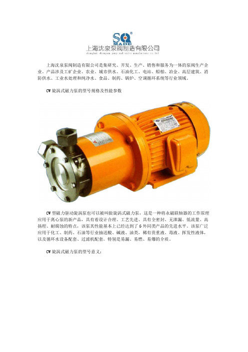
上海沈泉泵阀制造有限公司是集研究、开发、生产、销售和服务为一体的泵阀生产企业。
产品涉及工矿企业、农业、城市供水、石油化工、电站、船舶、冶金、高层建筑、消防供水、工业水处理和纯净水、食品、制药、锅炉、空调循环系统等行业领域。
CW旋涡式磁力泵的型号规格及性能参数
CW型磁力驱动旋涡泵也可以被叫做旋涡式磁力泵,这是一种将永磁联轴器的工作原理应用于离心泵的新产品,具有着设计合理、工艺先进、具有全密封、无泄漏、低流量、高扬程、耐腐蚀的特点,该泵其性能基本上已经达到了G外同类产品的先进水平。
该泵广泛应用于化工、制药、石油等行业抽送酸、碱液、油类,稀有贵重液、毒液、挥发性液体,以及循环水设备配套、过滤机配套。
特别是易漏、易燃、易爆的介质。
CW旋涡式磁力泵的型号意义:
CW型磁力驱动旋涡泵性能参数选型表:
好了,以上内容由上海沈泉泵阀制造有限公司为大J提供,希望能够对大J有所帮助。
艾迪斯莱·X20(c)SLX系列数字输入模块说明书

2 OverviewTable 2: Digital input modules3 Order dataX20SLX210/ X20SLX410X20SLX811X20SLX910Short descriptionIntelligent programmable modulessafe digital input module, safety controller, openSAFETY,SafeMOTION axes, 2 safe digital inputs, configurable input filter, 2 pulse outputs, 24 VDCsafe digital input module, safety controller, openSAFETY,SafeMOTION axes, 4 safe digital inputs, configurable input filter, 4 pulse outputs, 24 VDCX20 safe digital input module, coated, safety controller, openSAFETY, 11 openSAFETY nodes,4 SafeMOTION axes, 4 safe digital inputs, configurable input filter, 4 pulse outputs, 24 VDCsafe digital input module, safety controller, openSAFETY,SafeMOTION axes, 8 safe digital inputs, configurable input filter, 4 pulse outputs, 24 VDC, sin-safe digital input module, safety controller, openSAFETY,SafeMOTION axes, 20 safe digital inputs, configurable input filter, 4 pulse outputs, 24 VDCX20 safe digital input module, coated, safety controller, openSAFETY, 11 openSAFETY nodes,4 SafeMOTION axes, 20 safe digital inputs, configurable input filter, 4 pulse outputs, 24 VDCRequired accessoriesBus modulesX20 bus module, for X20 SafeIO modules, internal I/O power supply continuous, single-widthX20 bus module, for X20 SafeIO modules, internal I/O power supply continuousX20 bus module, for X20 SafeIO modules, with node number switch, internal I/O power supplycontinuousX20 bus module, coated, for X20 SafeIO modules, internal I/O power supply continuousTerminal blocksX20 terminal block, 12-pin, safety-keyedTable 3: X20SLX210, X20SLX410, X20cSLX410, X20SLX811, X20SLX910, X20cSLX910 - Order data4 Technical dataTable 4: X20SLX210, X20SLX410, X20cSLX410, X20SLX811, X20SLX910, X20cSLX910 - Technical data1)It is also important to take note of the danger warnings in the technical data sheet.2)If multiple SafeLOGIC-X controllers exist in the AS hardware tree, all but 1 must be disabled.3)Keep in mind that 8 BOOL count as 1 data point.4)Protection is provided for max. 30 minutes for continuous short circuits.Danger!Operating outside of technical data specifications is not permitted and can result in dangerous situ-ations.Information:For additional information about installation, see chapter "Installation notes for X20 safety modules"on page 67.X20SLXx10 - DeratingThe number of inputs that should be used at the same time depends on the operating temperature and the mounting orientation. The resulting amount can be looked up in the following table.The derating curve refers to operation at 28.8 VDC. When operated at 24 VDC and mounted horizontally, the derating curve is shifted to the right by the derating bonus specified in the technical data.If a dummy module is installed on the left, right or left and right next to the module, then the derating curve is shifted to the right by the derating bonus specified in the technical data (with horizontal mounting).X20SLX410X20SLX811X20SLX910Table 5: Derating in relation to operating temperature and mounting orientationInformation:Regardless of the values specified in the derating curve, the module cannot be operated above thevalues specified in the technical data.5 LED status indicatorsX20SLX210X20SLX410X20SLX811X20SLX910Table 6: Status displayDanger!Constantly lit "SE" LEDs indicate a defective module that must be replaced immediately.It is your responsibility to ensure that all necessary repair measures are initiated after an error occurs since subsequent errors can result in dangerous situations!6 PinoutsSI 1SI 2r 12e 000CSEX 20 S L X 210Pulse 1Pulse 2Figure 1: X20SLX210 - Pinout SI 1SI 2r 12e 000C SEX 20 S L X 410Pulse 1Pulse 234000CSI 3SI 4Pulse 3Pulse 4Figure 2: X20SLX410 - PinoutSI 1SI 2r 13e 24SEX 20 S L X 811Pulse 1Pulse 25768SI 3SI 4Pulse 3Pulse 4SI 7SI 5SI 8SI 6Figure 3: X20SLX811 - Pinout r 13e 14SEX 20 S L X 91015161718SI 9SI 10SI 11SI 12SI 5SI 6SI 7SI 8SI 1SI 2SI 3SI 4Pulse 1Pulse 3SI 151920123456789101112SI 16SI 14SI 13SI 20SI 19SI 18SI 17Pulse 4Pulse 2Figure 4: X20SLX910 - Pinout。
HLMP-EH32-MQ000中文资料
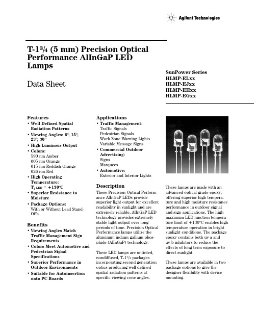
T-13/4 (5 mm) Precision Optical Performance AlInGaP LED LampsData SheetFeatures• Well Defined Spatial Radiation Patterns• Viewing Angles: 6°, 15°, 23°, 30°• High Luminous Output• Colors:590 nm Amber605 nm Orange615 nm Reddish-Orange626 nm Red• High Operating Temperature:T J LED=+130°C• Superior Resistance to Moisture• Package Options:With or Without Lead Stand-OffsBenefits• Viewing Angles Match Traffic Management Sign Requirements• Colors Meet Automotive and Pedestrian Signal Specifications• Superior Performance in Outdoor Environments• Suitable for Autoinsertion onto PC Boards Applications• Traffic Management:Traffic SignalsPedestrian SignalsWork Zone Warning LightsVariable Message Signs• Commercial OutdoorAdvertising:SignsMarquees• Automotive:Exterior and Interior LightsDescriptionThese Precision Optical Perform-ance AlInGaP LEDs providesuperior light output for excellentreadability in sunlight and areextremely reliable. AlInGaP LEDtechnology provides extremelystable light output over longperiods of time. Precision OpticalPerformance lamps utilize thealuminum indium gallium phos-phide (AlInGaP) technology.These LED lamps are untinted,nondiffused, T-13/4 packagesincorporating second generationoptics producing well definedspatial radiation patterns atspecific viewing cone angles.SunPower SeriesHLMP-ELxxHLMP-EJxxHLMP-EHxxHLMP-EGxxThese lamps are made with anadvanced optical grade epoxy,offering superior high tempera-ture and high moisture resistanceperformance in outdoor signaland sign applications. The highmaximum LED junction tempera-ture limit of +130°C enables hightemperature operation in brightsunlight conditions. The packageepoxy contains both uv-a anduv-b inhibitors to reduce theeffects of long term exposure todirect sunlight.These lamps are available in twopackage options to give thedesigner flexibility with devicemounting.Device Selection GuideTypicalViewing Color and Luminous Angle Dominant Lamps Without Standoffs Lamps With Standoffs Intensity Iv (mcd) [1,2] 2θ1/2Wavelength on Leads on Leads@ 20 mA (Deg.)[4](nm), Typ.[3] (Outline Drawing A)(Outline Drawing B)Min.Max.HLMP-EL08-VY000HLMP-EL10-VY000360013800HLMP-EL08-VYK00*360013800HLMP-EL08-VXK00*360010700HLMP-EL08-VX400**360010700HLMP-EL08-VX000360010700HLMP-EL08-WZ000HLMP-EL10-WZ000470018400HLMP-EL08-XZ400**620018400 Amber 590HLMP-EL08-XZ000620018400HLMP-EL08-XZK00*620018400HLMP-EL08-XY000620013800HLMP-EL08-XYK00*620013800HLMP-EL08-X1K00*620024100HLMP-EL08-X1000HLMP-EL10-X1000620024100 6°[5]HLMP-EJ08-WZ000HLMP-EJ10-WZ000470018400 Orange 605HLMP-EJ08-X1000HLMP-EJ10-X1000620024100HLMP-EJ08-Y2000HLMP-EJ10-Y2000800031000HLMP-EH08-UX000HLMP-EH10-UX000275010700HLMP-EH08-VY000HLMP-EH10-VY000360013800 Red-Orange 615HLMP-EH08-WZ000HLMP-EH10-WZ000470018400HLMP-EH08-X1000HLMP-EH10-X1000620024100HLMP-EH08-Y2000HLMP-EH10-Y2000800031000HLMP-EG08-VW00036008300HLMP-EG08-VY000HLMP-EG10-VY000360013800HLMP-EG08-WZ000HLMP-EG10-WZ000470018400 Red 626HLMP-EG08-X1000HLMP-EG10-X1000620024100HLMP-EG08-YZ000800018400HLMP-EG08-Y1000800024100HLMP-EG08-Y2000HLMP-EG10-Y2000800031000 Notes:1. The luminous intensity is measured on the mechanical axis of the lamp package.2.The optical axis is closely aligned with the package mechanical axis.3. The dominant wavelength, λd, is derived from the CIE Chromaticity Diagram and represents the color of the lamp.4. θ1/2 is the off-axis angle where the luminous intensity is one half the on-axis intensity.5.The intensity of narrow viewing angle lamps is measured at the intensity peak.Part numbers in bold are recommended for new designs.*HLMP-xLxx-xxK00 are selected to amber color bins 2 and 4 only.Device Selection Guide (Continued)TypicalViewing Color and Luminous Angle Dominant Lamps Without Standoffs Lamps With Standoffs Intensity Iv (mcd) [1,2] 2θ1/2Wavelength on Leads on Leads@ 20 mA (Deg.)[4](nm), Typ.[3] (Outline Drawing A)(Outline Drawing B)Min.Max.HLMP-EL15-PS000HLMP-EL17-PS0007652900HLMP-EL15-QR00010002200HLMP-EL15-QRK00*10002200HLMP-EL15-QS00010002900 Amber 590HLMP-EL15-QS400**10002900HLMP-EL15-QSK00*10002900HLMP-EL15-QT000HLMP-EL17-QT00010003700 15°HLMP-EL15-QTK00*10003700HLMP-EL15-RU000HLMP-EL17-RU00013004800HLMP-EJ15-PS0007652900 Orange 605HLMP-EJ15-RU000HLMP-EJ17-RU00013004800HLMP-EJ15-SV000HLMP-EJ17-SV00016506300 Red-Orange 615HLMP-EH15-QT000HLMP-EH17-QT00010003700HLMP-EH15-RU000HLMP-EH17-RU00013004800HLMP-EG15-PS0007652900 Red 626HLMP-EG15-QT000HLMP-EG17-QT00010003700HLMP-EG15-RU000HLMP-EG17-RU00013004800HLMP-EL24-MQ0004501730HLMP-EL24-NR000HLMP-EL26-NR0005902200HLMP-EL24-PS000HLMP-EL26-PS0007652900HLMP-EL24-PSK00*7652900HLMP-EL24-PR400**7652200HLMP-EL24-PQK00*7651730 Amber 590HLMP-EL24-QR00010002200HLMP-EL24-QRK00*10002200 23°HLMP-EL24-QS00010002900HLMP-EL24-QSK00*10002900HLMP-EL24-QS400**10002900HLMP-EL24-QT000HLMP-EL26-QT00010003700HLMP-EL24-QTK00*10003700 Notes:1. The luminous intensity is measured on the mechanical axis of the lamp package.2.The optical axis is closely aligned with the package mechanical axis.3. The dominant wavelength, λd, is derived from the CIE Chromaticity Diagram and represents the color of the lamp.4. θ1/2 is the off-axis angle where the luminous intensity is one half the on-axis intensity.5.The intensity of narrow viewing angle lamps is measured at the intensity peak.Device Selection Guide (Continued)TypicalViewing Color and Luminous Angle Dominant Lamps Without Standoffs Lamps With Standoffs Intensity Iv (mcd) [1,2] 2θ1/2Wavelength on Leads on Leads@ 20 mA (Deg.)[4](nm), Typ.[3] (Outline Drawing A)(Outline Drawing B)Min.Max.Orange 605HLMP-EJ24-QT000HLMP-EJ26-QT00010003700HLMP-EJ24-RU000HLMP-EJ26-RU00013004800HLMP-EH26-PS0007652900 Red-Orange 615HLMP-EH24-QT000HLMP-EH26-QT00010003700 23ºHLMP-EH24-RU000HLMP-EH26-RU00013004800HLMP-EG24-PS000HLMP-EG26-PS0007652900 Red 626HLMP-EG24-QT000HLMP-EG26-QT00010003700HLMP-EG24-RU000HLMP-EG26-RU00013004800HLMP-EL30-MQ000HLMP-EL32-MQ0004501730HLMP-EL30-NR000HLMP-EL32-NR0005902200HLMP-EL30-PQ0007651730HLMP-EL30-PQK00*7651730 Amber 590HLMP-EL30-PR0007652200HLMP-EL30-PR400**7652200HLMP-EL30-PRK00*7652200HLMP-EL30-PS000HLMP-EL32-PS0007652900HLMP-EL30-PSK00*7652900 30°HLMP-EJ30-MQ0004501730 Orange 605HLMP-EJ30-NR000HLMP-EJ32-NR0005902200HLMP-EJ30-PS000HLMP-EJ32-PS0007652900HLMP-EH30-MQ000HLMP-EH32-MQ0004501730 Red-Orange 615HLMP-EH30-NR000HLMP-EH32-NR0005902200HLMP-EH30-PS000HLMP-EH32-PS0007652900HLMP-EG30-KN0002701010HLMP-EG30-MQ000HLMP-EG32-MQ0004501730HLMP-EG30-NQ0005901730HLMP-EG30-NR000HLMP-EG32-NR0005902200 Red 626HLMP-EG30-PQ0007651730HLMP-EG30-PR0007652200HLMP-EG30-PS000HLMP-EG32-PS0007652900 Notes:1. The luminous intensity is measured on the mechanical axis of the lamp package.2.The optical axis is closely aligned with the package mechanical axis.3. The dominant wavelength, λd, is derived from the CIE Chromaticity Diagram and represents the color of the lamp.4. θ1/2 is the off-axis angle where the luminous intensity is one half the on-axis intensity.5.The intensity of narrow viewing angle lamps is measured at the intensity peak.Part Numbering SystemHLMP-x x xx-x x x xxMechanical Options00: Bulk PackagingDD: Ammo PackYY: Flexi-Bin; Bulk PackagingZZ: Flexi-Bin; Ammo PackColor Bin Selections0: No color bin limitation4: Amber color bin 4 onlyK: Amber color bins 2 and 4 onlyMaximum Intensity Bin0: No Iv bin limitationMinimum Intensity BinViewing Angle & Lead Stand Offs08: 6 deg without lead stand offs10: 6 deg with lead stand offs15: 15 deg without lead stand offs17: 15 deg with lead stand offs24: 23 deg without lead stand offs26: 23 deg with lead stand offs30: 30 deg without lead stand offs32: 30 deg with lead stand offsColorG: 626 nm RedH: 615 nm Red-OrangeJ: 605 nm OrangeL: 590 nm AmberPackageE: 5 mm RoundNOTES:1. ALL DIMENSIONS ARE IN MILLIMETERS (INCHES).2. LEADS ARE MILD STEEL, SOLDER DIPPED.3. TAPERS SHOWN AT TOP OF LEADS (BOTTOM OF LAMP PACKAGE) INDICATE AN EPOXY MENISCUS THAT MAY EXTEND ABOUT 1 mm (0.040 in.) DOWN THE LEADS.4. RECOMMENDED PC BOARD HOLE DIAMETERS:• LAMP PACKAGE A WITHOUT STAND-OFFS: FLUSH MOUNTING AT BASE OF LAMP PACKAGE = 1.143/1.067 (0.044/0.042).• LAMP PACKAGE B WITH STAND-OFFS: MOUNTING AT LEAD STAND-OFFS = 0.965/0.889 (0.038/0.035).5. FOR DOME HEIGHTS ABOVE LEAD STAND-OFF SEATING PLANE, d, LAMP PACKAGE B, SEE TABLE.BPackage DimensionsA(0.039)(0.039)PART NO.d HLMP-XX1012.37 ± 0.25 (0.487 ± 0.010)HLMP-XX1712.42 ± 0.25 (0.489 ± 0.010)HLMP-XX2612.52 ± 0.25 (0.493 ± 0.010)HLMP-XX3211.96 ± 0.25 (0.471 ± 0.010)Electrical/Optical Characteristics at T A = 25°CParameter SymbolMin.Typ.Max.UnitsTest Conditions Forward VoltageI F = 20 mAAmber (λd = 590 nm) 2.02Orange (λd = 605 nm)V F 1.98 2.4VRed-Orange (λd = 615 nm) 1.94Red (λd = 626 nm) 1.90Reverse Voltage V R 520VI F = 100 µAPeak Wavelength:Peak of Wavelength of Amber (λd = 590 nm)592Spectral Distribution Orange (λd = 605 nm)λPEAK 609nmat I F = 20 mARed-Orange (λd = 615 nm)621Red (λd = 626 nm)635Spectral Halfwidth∆λ1/217nmWavelength Width at Spectral Distribution 1/2 Power Point at I F = 20 mASpeed of Response τs 20ns Exponential Time Constant, e -t/τCapacitanceC 40pF V F = 0, f = 1 MHzThermal Resistance R θJ-PIN240°C/WLED Junction-to-Cathode LeadLuminous Efficacy [1]Emitted LuminousAmber (λd = 590 nm)480Power/Emitted Radiant Orange (λd = 605 nm)ηv370lm/WPowerRed-Orange (λd = 615 nm)260Red (λd = 626 nm)150Note:Absolute Maximum Ratings at T A = 25°CDC Forward Current [1,2,3]............................................................50 mA Peak Pulsed Forward Current [2,3]..............................................100 mA Average Forward Current [3].........................................................30 mA Reverse Voltage (I R = 100 µA).........................................................5 V LED Junction Temperature..........................................................130°C Operating Temperature ..............................................-40°C to +100°C Storage Temperature ..................................................-40°C to +120°C Dip/Drag Soldering Temperature...........................260°C for 6 seconds Through-the-Wave Preheat Temperature......................................145°C Through-the-Wave Solder Temperature.................245°C for 3 seconds [1.59 mm (0.060 in.) below seating plane]Notes:1. Derate linearly as shown in Figure 4.2. For long term performance with minimal light output degradation, drive currentsbetween 10 mA and 30 mA are recommended. For more information on recommended drive conditions, please refer to Application Brief I-024 (5966-3087E).3. Operating at currents below 1 mA is not recommended. Please contact your local representative for further information.sFigure 2. Forward Current vs.Forward Voltage.Figure 3. Relative Luminous Intensity vs. Forward Current.Figure 4. Maximum Forward Current vs. Ambient Temperature. Derating Based on T JMAX = 130°C.Figure 1. Relative Intensity vs. Peak Wavelength.I F – F O R W A R D C U R R E N T – m AT A – AMBIENT TEMPERATURE – °CR E L A T I V E I N T E N S I T Y – %1000θ – ANGULAR DISPLACEMENT – DEGREES8060507020-20-15103040-1051015202590-25-5WAVELENGTH – nmR E L A T I V E I N T E N S I T YR E L A T I V E L U M I N O U S I N T E N S I T Y (N O R M A L I Z E D A T 20 m A )00I F – DC FORWARD CURRENT – mA 403.02.01.51.00.520602.5C U R R E NT – m AV F – FORWARD VOLTAGE – VBin Name Min.Max.K 310400L 400520M 520680N680880P 8801150Q 11501500R 15001900S 19002500T 25003200U 32004200V 42005500W 55007200X 72009300Y 930012000Z 12000160001160002100022100027000Intensity Bin Limits (mcd at 20 mA)Tolerance for each bin limit is ± 15%.Bin Name Min.Max.1584.5587.02587.0589.54589.5592.06592.0594.5Amber Color Bin Limits (nm at 20 mA)Tolerance for each bin limit is ± 0.5 nm.Note:1.Bin categories are established for classification of products. Products Figure 7. Representative Spatial Radiation Pattern for 23° Viewing Angle Lamps.R E L A T I V E I N T E N S I T Y – %1000θ – ANGULAR DISPLACEMENT – DEGREES806050702010304090-20-15-10510152025-25-5R E L A T I V E I N T E N S I T Y – %1000θ – ANGULAR DISPLACEMENT – DEGREES806050702010304090-20-15-10510152025-25-5R E L A T I V E I N T E N S I T Y – %1000θ – ANGULAR DISPLACEMENT – DEGREES806050702010304090-20-15-10510152025-25-5Figure 6. Representative Spatial Radiation Pattern for 15° Viewing Angle Lamps.Data subject to change.Copyright © 2001 Agilent Technologies, Inc. August 13, 2001。
高亮度AlInGaP LED灯数据表单说明书
HLMP-EGxx, HLMP-ELxx and HLMP-EHxxT-1¾ (5mm) Extra High Brightness AlInGaP LED LampsData SheetDescription These Precision Optical Performance Al I nGaP LEDs provide superior light output for excellent readability in sunlight and are extremely reliable. AlI nGaP LED tech-nology provides extremely stable light output over longperiods of time. Precision Optical Performance lampsutilize the aluminum indium gallium phosphide (AlInGaP)technology. These LED lamps are untinted, T-1¾ packages incorpo-rating second generation optics producing well defined spatial radiation patterns at specific viewing cone angles.These lamps are made with an advanced optical grade epoxy offering superior high temperature and highmoisture resistance performance in outdoor signal andsign application. The maximum LED junction tempera-ture limit of +130°C enables high temperature operationin bright sunlight conditions. The epoxy contains both uv-a and uv-b inhibitors to reduce the effects of longterm exposure to direct sunlight.Benefits• Superior performance for outdoor environments •Suitable for auto-insertion onto PC board Features• Viewing angle: 15°, 23°, 30°• High luminous output • Colors:590nm Amber 615nm Red-Orange 626nm Red • Package options: With or without lead standoff • Superior resistance to moisture• Untinted non-diffused for 15° and 30° lamps • Untinted diffused for 23° lampsApplications • Traffic management:- Traffic signals - Pedestrian signals- Work zone warning lights- Variable message signs• Commercial outdoor advertising - Signs- MarqueesPackage DimensionNOTES:1. ALL DIMENSIONS ARE IN MILLIMETERS (INCHES).2. TAPERS SHOWN AT TOP OF LEADS (BOTTOM OF LAMP PACKAGE) INDICATE AN EPOXY MENISCUS THAT MAY EXTEND ABOUT 1 mm (0.040 in.) DOWN THE LEADS.3. RECOMMENDED PC BOARD HOLE DIAMETERS:-LAMP PACKAGE A WITHOUT STAND-OFFS: FLUSH MOUNTING AT BASE OF LAMP PACKAGE = 1.143/1.067 (0.044/0.042).-LAMP PACKAGE B WITH STAND-OFFS: MOUNTING AT LEAD STAND-OFFS = 0.965/0.889 (0.038/0.035).4. FOR DOME HEIGHTS ABOVE LEAD STAND-OFF SEATING PLANE, d, LAMP PACKAGE B, SEE TABLE.BA(0.039)(0.039)PART NO.d HLMP-XX1312.42 ± 0.25(0.489 ± 0.010)HLMP-XX2311.59± 0.25(0.446± 0.010)HLMP-XX3711.96 ± 0.25(0.471 ± 0.010)5. FOR IDENTIFICATION OF POLARITY AFTER THE LEADS ARE TRIMMED OFF, PLEASE REFER TO THE ILLUSTRATION BELOW:7. MAJOR HEAT PATH IS THROUGH THE ANODE LEADCATHODEDevice Selection GuideTypical Viewing Angle 2θ½ (Deg) [4]Color and DominantWavelength (nm), Typ. [3]Lamps withoutStandoffs on Leads(Outline Drawing A)Lamps withStandoffs on Leads(Outline Drawing B)Luminous IntensityIv (mcd) [1,2,5] @ 20mAMin.Max.15°Amber 590HLMP-EL12-VY0DD HLMP-EL13-VY0DD420012000HLMP-EL12-XYKDD720012000 Red-Orange 615HLMP-EH12-VY0DD HLMP-EH13-VY0DD420012000Red 626HLMP-EG12-VY0DD HLMP-EG13-VY0DD420012000HLMP-EG12-WX0DD55009300 23°Amber 590HLMP-EL22-UXKDD HLMP-EL23-UXKDD32009300HLMP-EL22-UX0DD HLMP-EL23-UX0DD32009300HLMP-EL22-VWKDD42007200 Red-Orange 615HLMP-EH22-TW0DD HLMP-EH23-TW0DD25007200Red 626HLMP-EG22-UX0DD HLMP-EG23-UX0DD32009300HLMP-EG22-VW0DD42007200 30°Amber 590HLMP-EL35-TW0DD HLMP-EL37-TW0DD25007200HLMP-EL35-TWKDD HLMP-EL37-TWKDD25007200HLMP-EL35-UVKDD32005500 Red-Orange 615HLMP-EH35-SV0DD HLMP-EH37-SV0DD19005500Red 626HLMP-EG35-TW0DD HLMP-EG37-TW0DD25007200HLMP-EG35-UV0DD32005500 Notes:1. The luminous intensity is measured on the mechanical axis of the lamp package.2. The optical axis is closely aligned with the package mechanical axis.3. Dominant wavelength, λd, is derived from the CIE Chromaticity Diagram and represents the color of the lamp.4. θ½ is the off-axis angle where the luminous intensity is half the on-axis intensity.5. Tolerance for each intensity bin limit is ± 15%.Part Numbering SystemAbsolute Maximum Ratings at T A = 25°CDC Forward Current [1]50 mA Peak Pulsed Forward Current 100 mA Average Forward Current 30 mA Reverse Voltage (Ir = 100 µA) 5 VOperating Temperature –40°C to +100°C Storage Temperature–40°C to +100°CNotes:1.Derate linearly as shown in Figure 4.Mechanical Options 00 : Bulk Packaging DD : Ammo PackYY : Flexi-Bin; Bulk Packaging ZZ : Flexi-Bin; Ammo Pack Color Bin Selections 0 : Full color distribution 2 : Amber color bin 2 only 4 : Amber color bin 4 onlyK : Amber color bin 2 and 4 only Z : Special Vf Bin RangeMaximum Intensity Bin0 : No maximum intensity bin limitation Minimum Intensity BinViewing Angle and Lead Standoffs 12 : 15 deg without lead standoffs 13 : 15 deg with lead standoffs 22 : 23 deg without lead standoffs 23 : 23 deg with lead standoffs 35 : 30 deg without lead standoffs 37 : 30 deg with lead standoffs ColorG : 626nm RedH : 615nm Red-Orange L : 590nm AmberNote: Please refer to AB 5337 for complete information on part numbering system.Electrical/ Optical Characteristics at T A = 25ºCParameter Symbol Minimum Average Maximum Units Test Condition Forward VoltageAmber RedRed-Orange V F 1.802.202.102.002.40VI F = 20mAPeak WavelengthAmber RedRed-Orange λPEAK590626615nmI F = 20mADominant Wavelength [1]Amber RedRed-Orange λd584.5620.0612.0594.5630.0621.7nmI F = 20mAReverse Voltage V R5V I R = 100μASpectral Halfwidth Dλ½17nm I F = 20 mACapacitance C40pF V F = 0, f = 1 MHzThermal Resistance RθJ-PIN240ºC/W LED Junction-to-Anode Lead Luminous Efficacy [2]AmberRedRed-Orange h V480150260lm/WEmitted Luminous Flux/EmittedRadiant FluxLuminous Flux j V1300mlm I F = 20mALuminous Efficiency [3]h e30lm/W Emitted Luminous Flux/ ElectricalPowerNotes:1. The dominant wavelength, λd is derived from the CIE Chromaticity Diagram referenced to Illuminant E. Tolerance for each color of dominantwavelength is +/- 0.5nm.2. The radiant intensity, Ie in watts per steradian, maybe found from the equation Ie = Iv / ηV where Iv is the luminous intensity in candela and ηV isthe luminous efficacy in lumens/watt.3. h e = j V / I F x V F, where j V is the emitted luminous flux, I F is electrical forward current and V Fis the forward voltage.Figure 1. Relative intensity vs. peak wavelengthFORWARD VOLTAGE - VF O R W A R D C U R R E N T - m A0.511.522.501020304050DC FORWARD CURRENT - mAR E L A T I V E L U M I N O U S I N T E N S I T Y (N O R M A L I Z E D A T 20 m A )510152025303540455055020406080100120T A - AMBIENT TEMPERATURE - ºCI F - F O R W A R D C U R R E N T - m A00.10.20.30.40.50.60.70.80.91-90-60-300306090ANGULAR DISPLACEMENT - DEGREESN O R M A L I Z E D I N T E N S I T Y00.10.20.30.40.50.60.70.80.91-90-60-300306090ANGULAR DISPLACEMENT -DEGREESN O R M A L I Z E D I N T E N S I T Y0.10.20.30.40.50.60.70.80.91-90-60-300306090ANGULAR DISPLACEMENT - DEGREESN O R M A L I Z E D I N T E N S I T YFigure 2. Forward current vs. forward voltageFigure 3. Relative luminous intensity vs. forward currentFigure 4. Maximum forward current vs. ambient temperatureFigure 5. Representative spatial radiation pattern for 15° viewing angle lampsFigure 6. Representative spatial radiation pattern for 23° viewing angle lamps Figure 7. Representative spatial radiation pattern for 30° viewing angle lampsIntensity Bin Limits (mcd at 20mA)Bin NameMinimumMaximumR 15001900S 19002500T 25003200U 32004200V 42005500W 55007200X 72009300Y 930012000Z 12000160001160002100022100027000Tolerance for each bin limit is ± 15%Forward Voltage Bin Limits (V at 20mA)Bin NameMinimumMaximumVD 1.8 2.0VA 2.0 2.2VB2.22.4Tolerance for each bin limit is ± 0.05VAmber Color Bin Limits (nm at 20mA)Bin NameMinimumMaximum1584.5587.02587.0589.54589.5592.06592.0594.5Tolerance for each bin limit is ± 0.5nmNote: Bin categories are established for classification of products. Products may not available in all bin categories.Figure 8. Relative light output vs. junction temperatureJUNCTION TEMPERATURE - °CR E L A T I V E L O P (N O R M A L I Z E A T 25 °C )Precautions:Lead Forming:•The leads of an LED lamp may be preformed or cut to length prior to insertion and soldering on PC board.•For better control, it is recommended to use proper tool to precisely form and cut the leads to applicable length rather than doing it manually.•If manual lead cutting is necessary, cut the leads after the soldering process. The solder connection forms a mechanical ground which prevents mechanical stress due to lead cutting from traveling into LED package. This is highly recommended for hand solder operation, as the excess lead length also acts as small heat sink. Soldering and Handling:• Care must be taken during PCB assembly and soldering process to prevent damage to the LED component.•LED component may be effectively hand soldered to PCB. However, it is only recommended under unavoidable circumstances such as rework. The closest manual soldering distance of the soldering heat source (soldering iron’s tip) to the body is 1.59mm. Soldering the LED using soldering iron tip closer than1.59mm might damage the LED.•ESD precaution must be properly applied on the soldering station and personnel to prevent ESD damage to the LED component that is ESD sensitive. Do refer to Avago application note AN 1142 for details. The soldering iron used should have grounded tip to ensure electrostatic charge is properly grounded.•Recommended soldering condition:Wave Soldering [1, 2]Manual Solder DippingPre-heat temperature105 °C Max.-Preheat time60 sec Max-Peak temperature250 °C Max.260 °C Max.Dwell time 3 sec Max. 5 sec MaxNote:1. Above conditions refers to measurement with thermocouplemounted at the bottom of PCB.2. It is recommended to use only bottom preheaters in order to reducethermal stress experienced by LED.•Wave soldering parameters must be set and maintained according to the recommended temperature and dwell time. Customer is advised to perform daily check on the soldering profile to ensure that it is always conforming to recommended soldering conditions.Note:1. PCB with different size and design (component density) will havedifferent heat mass (heat capacity). This might cause a change in temperature experienced by the board if same wave soldering setting is used. So, it is recommended to re-calibrate the soldering profile again before loading a new type of PCB.2. Avago Technologies’ high brightness LED are using high efficiencyLED die with single wire bond as shown below. Customer is advised to take extra precaution during wave soldering to ensure that the maximum wave temperature does not exceed 250°C and the solder contact time does not exceeding 3sec. Over-stressing the LED during soldering process might cause premature failure to the LED due to delamination.Avago Technologies LED configurationNote: Electrical connection between bottom surface of LED die and the lead frame is achieved through conductive paste.•Any alignment fixture that is being applied during wave soldering should be loosely fitted and should not apply weight or force on LED. Non metal material is recommended as it will absorb less heat during wave soldering process.Note: In order to further assist customer in designing jig accurately that fit Avago Technologies’ product, 3D model of the product is available upon request.•At elevated temperature, LED is more susceptible to mechanical stress. Therefore, PCB must allowed to cool down to room temperature prior to handling, which includes removal of alignment fixture or pallet.•If PCB board contains both through hole (TH) LED and other surface mount components, it is recommended that surface mount components be soldered on the top side of the PCB. If surface mount need to be on the bottom side, these components should be soldered using reflow soldering prior to insertion the TH LED.•Recommended PC board plated through holes (PTH) size for LED component leads.LED componentlead size DiagonalPlated throughhole diameter0.45 x 0.45 mm(0.018x 0.018 inch)0.636 mm(0.025 inch)0.98 to 1.08 mm(0.039 to 0.043 inch)0.50 x 0.50 mm(0.020x 0.020 inch)0.707 mm(0.028 inch)1.05 to 1.15 mm(0.041 to 0.045 inch)•Over-sizing the PTH can lead to twisted LED after clinching. On the other hand under sizing the PTH can cause difficulty inserting the TH LEDFigure 10. Dimension for ammo packFigure 9. Recommended Wave Soldering ProfileRecommended Wave Soldering ProfileAmmo Packs DrawingNote: The ammo-packs drawing is applicable for packaging option –DD & -ZZ and regardless standoff or non-standoff25020015010050TIME (SECONDS)Recommended solder: Sn63 (Leaded solder alloy)SAC305 (Lead free solder alloy)Flux: Rosin uxSolder bath temperature: 245°C± 5°C (maximum peak temperature = 250°C)Dwell time: 1.5 sec - 3.0 sec (maximum = 3sec)Note: Allow for board to be su ciently cooled to room temperature before exerting T E M P E R A T U R E (°C )mechanical force.Note: The dimension for ammo pack is applicable for the device with standoff and without standoff. Figure 11. The arrangement of unit in ammo packPackaging Label:(i) Avago Mother Label: (Available on packaging box of ammo pack and shipping box)DeptID:Made In: Country of Origin(ii) Avago Baby Label (Only available on bulk packaging)Acronyms and Definition:BIN:(i) Color bin only or VF bin only(Applicable for part number with color bins but without VF bin OR part number with VF bins and no color bin)OR(ii) Color bin incorporated with VF Bin(Applicable for part number that have both color bin and VF bin)Example:(i) Color bin only or VF bin only BIN: 2 (represent color bin 2 only) BIN: VB (represent VF bin “VB” only)(ii) Color bin incorporate with VF BinVB: VF bin “VB”2: Color bin 2 only。
海霖科技 D23 调速抽打气泵系列 产品说明书
D23调速抽打气泵系列产品说明书文档版本17发布日期2022-08版权所有©成都海霖科技有限公司2018。
保留一切权利。
非经本公司书面许可,任何单位和个人不得擅自摘抄、复制本文档内容的部分或全部,并不得以任何形式传播。
商标声明商标为成都海霖科技有限公司的商标。
本文档提及的其他所有商标或注册商标,由各自的所有人拥有。
注意您购买的产品、服务或特性等应受成都海霖科技有限公司相关合同和条款的约束,本文档中描述的全部或部分产品、服务或特性可能未包含在您的购买或使用范围之内。
除非合同另有约定,成都海霖科技有限公司对本文档内容不做任何明示或默示的声明或保证。
由于产品版本升级或其他原因,本文档内容会不定期进行更新。
除非另有约定,本文档仅作为使用指导,本文档中的所有陈述、信息和建议不构成任何明示或暗示的担保。
成都海霖科技有限公司地址:成都市双流区牧华路二段杰邦孵化谷邮编:610000网址:电话:************前言摘要本文为D23调速真空泵系列产品的相关说明,用于指导相关技术人员初步了解该产品特性。
读者对象本文档适用于负责产品研发的技术人员,您应该非常了解您产品,并对所需微型泵的相关参数、规格大小等信息有明确概念。
关键字PWM调速、相关参数、接线说明修改记录修改记录累积了每次文档更新的说明。
最新版本的文档包含以前所有文档版本的更新内容。
目录前言 (I)修改记录 (II)目录 (1)1产品特性 (2)1.1体积小巧 (2)1.2无刷电机 (2)1.3保护功能 (2)1.4良好的气密性 (2)2功能 (3)2.1调速功能 (3)2.2启停功能 (3)2.3转速反馈 (3)3技术参数 (4)3.1性能参数 (4)3.2可靠性参数 (5)3.3版本说明 (7)3.4工况.................................................................................................................错误!未定义书签。
摩尔晟AC DC转换器LD20-23BxxR2系列产品说明书
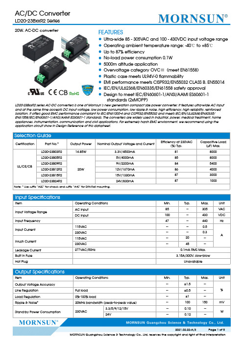
20W,AC-DC converter FEATURES●Ultra-wide85-305VAC and100-430VDC input voltage range●Operating ambient temperature range:-40℃to+85℃●Up to87%efficiency●No-load power consumption0.1W●5000m altitude application●Overvoltage category OVCⅢ(meet EN61558)●Plastic case meets UL94V-0flammability●EMI performance meets CISPR32/EN55032CLASS B,EN55014●IEC/EN/UL62368/EN60335/EN61558safety approval●Design to meet IEC/EN60601-1/ANSI/AAMI ES60601-1standards(2xMOPP)CB RoHSLD20-23BxxR2series AC-DC converters is one of Mornsun’s new generation compact size power converter.It features ultra-wide AC input and at the same time accepts DC input voltage,low power consumption,low ripple&noise,high efficiency,high reliability,reinforced isolation.It offers good EMC performance compliant to IEC/EN61000-4and CISPR32/EN55032and meets IEC/EN/UL62368/EN60335/EN61558/IEC/EN60601-1/ANSI/AAMI ES60601-1standards.The converters are widely used in industrial,power,medical treatment,home appliances,instrumentation,communication and civil applications.For extremely harsh EMC environment,we recommend using the application circuit show in Design Reference of this datasheet.Selection GuideCertification Part No.*Output Power Nominal Output Voltage and CurrentEfficiency at230V AC(%)Typ.Capacitive Load(µF)Max.UL/CE/CBLD20-23B03R214.85W 3.3V/4500mA818000LD20-23B05R220W5V/4000mA858000 LD20-23B09R29V/2200mA845400LD20-23B12R212V/1670mA864000LD20-23B15R215V/1330mA873000LD20-23B24R224V/830mA871000 Note:*Use suffix”A2S”for chassis and suffix”A4S”for DIN-Rail mounting.Input SpecificationsItem Operating Conditions Min.Typ.Max.UnitInput Voltage RangeAC input85--305V ACDC input100--430VDC Input Frequency47--440Hz Input Current115VAC----0.5A230VAC----0.3Inrush Current115VAC--20--230VAC--45--Leakage Current277VAC/50Hz0.1mA RMS Max.Built In Fuse 3.15A/300V,slow-blowHot Plug UnavailableOutput SpecificationsItem Operating Conditions Min.Typ.Max.Unit Output Voltage Accuracy--±1.5--% Line Regulation Full load--±0.5--Load Regulation0%-100%load--±1--Ripple&Noise*20MHz bandwidth(peak-to-peak value)--100150mV Stand-by Power Consumption230V AC3.3/5/9/12/15V--0.10--W24V--0.12--Temperature Coefficient--±0.02--%/°C Short Circuit Protection Hiccup,continuous,self-recovery Over-current Protection≥110%Io,self-recoveryOver-voltage Protection 3.3/5V output≤7.5VDC(Output voltage clamp or hiccup) 9V output≤16VDC(Output voltage clamp or hiccup) 12/15V output≤20VDC(Output voltage clamp or hiccup) 24V output≤30VDC(Output voltage clamp or hiccup)Minimum Load0----%Hold-up Time 115VAC input--8--ms 230VAC input--50--Note:*The“Tip and barrel method”is used for ripple and noise test,output parallel10uF electrolytic capacitor and1uF ceramic capacitor,please refer to AC-DC Converter Application Notes for specific information.General SpecificationsItem Operating Conditions Min.Typ.Max.UnitIsolation Input-output Electric Strength Test for1min.,leakage current<5mA4000----V ACInsulationResistanceInput-output At500VDC100----MΩOperating Temperature-40--+85°C Storage Temperature-40--+85Storage Humidity----95%RHSoldering Temperature Wave-soldering260±5℃;time:5-10s Manual-welding360±10℃;time:3-5sSwitching Frequency--65--kHzPower Derating -40°C to-25°C85V AC-165V AC 2.0----%/°C +50°C to+70°C 3.3/5/9V 2.5----+55°C to+70°C12/15/24V 3.33----+70℃to+85℃ 1.33----85V AC-100V AC 2.0----%/VAC 277VAC-305V AC0.71----2000m-5000m 6.7----%/KmSafety Standard IEC/EN/UL62368/EN60335/EN61558/EN60601 Safety Certification UL/EN/IEC62368/EN60335/EN61558Safety Class CLASS I IMTBF MIL-HDBK-217F@25°C>1,500,000hDesigned life230V AC Ta:25℃100%load>130x103h Ta:55℃100%load>16x103h Ta:55℃80%load>27x103hMechanical SpecificationsCase Material Black plastic,flame-retardant and heat-resistant(UL94V-0)Dimension DIP package52.40x27.20x24.00mm A2S chassis mounting76.00x31.50x32.80mm A4S Din-Rail mounting76.00x31.50x37.40mmWeight DIP package55g(Typ.) A2S chassis mounting75g(Typ.) A4S Din-Rail mounting95g(Typ.)Cooling method Free air convectionElectromagnetic Compatibility (EMC)EmissionsCECISPR32/EN55032CLASS BCISPR11/EN55011CLASS B EN55014-1RECISPR32/EN55032CLASS BCISPR11/EN55011CLASS B EN55014-1Flicker IEC/EN6100-3-3EN55014-1ImmunityESD IEC/EN 61000-4-2Contact ±6KV /Air ±8KV Perf.Criteria A IEC/EN55014-2Perf.Criteria A RSIEC/EN61000-4-310V/mperf.Criteria A IEC/EN55014-2perf.Criteria A EFTIEC/EN61000-4-4±2KVperf.Criteria A IEC/EN61000-4-4±4KV(See Fig.2for recommended circuit)perf.Criteria A IEC/EN55014-2perf.Criteria A SurgeIEC/EN61000-4-5line to line ±1KVperf.Criteria A IEC/EN61000-4-5line to line ±2KV (See Fig.2for recommended circuit)perf.Criteria A IEC/EN55014-2perf.Criteria A CS IEC/EN61000-4-610Vr.m.s perf.Criteria A IEC/EN55014-2perf.Criteria A PFMFIEC/EN6100-4-810A/m perf.Criteria A IEC/EN55014-2perf.Criteria A Voltage dip,short interruption and voltage variationIEC/EN61000-4-110%,70%perf.Criteria B IEC/EN55014-2perf.Criteria BProduct Characteristic CurveNote:①With an AC input between 85-100V/277-305VAC and a DC input between 100-120V/390-430VDC,the output power must be derated as pertemperature derating curves;②This product is suitable for applications using natural air cooling;for applications in closed environment please consult factory or one of our FAE.Design Reference1.Typical applicationFig.1:Typical circuit diagramPart No.C1C2TVSLD20-23B03R21µF/50V 10µF/16V SMBJ7.0ALD20-23B05R210µF/16V SMBJ7.0ALD20-23B09R210µF/25V SMBJ12ALD20-23B12R210µF/25V SMBJ20ALD20-23B15R210µF/25V SMBJ20ALD20-23B24R210µF/35V SMBJ30AOutput Filter Components:①C1is a ceramic capacitor used for filtering high-frequency noise and TVS is a recommended suppressor diode to protect the application in case of a converter failure;②This circuit is recommended for indoor use.2.EMC compliance recommended circuitFig2:EMC application circuit with higher requirementsComponent Recommended valueFUSE 3.15A/300V,slow-blow,requiredMOV S14K350R13Ω/3W3.For additional information please refer to application notes on . Dimensions and Recommended LayoutA2S DimensionsA4S DimensionsNote:1.For additional information on Product Packaging please refer to .Packaging bag number:58220011(DIPpackage);58220022(A2S/A4S package);2.If the product is not operated within the required load range,the product performance cannot be guaranteed to comply with allparameters in the datasheet;3.Unless otherwise specified,parameters in this datasheet were measured under the conditions of Ta=25℃,humidity<75%with nominalinput voltage and rated output load;4.All index testing methods in this datasheet are based on our company corporate standards;5.We can provide product customization service,please contact our technicians directly for specific information;6.Products are related to laws and regulations:see"Features"and"EMC";7.Our products shall be classified according to ISO14001and related environmental laws and regulations,and shall be handled byqualified units.Mornsun Guangzhou Science&Technology Co.,Ltd.Address:No.5,Kehui St.1,Kehui Development Center,Science Ave.,Guangzhou Science City,Huangpu District,Guangzhou,P.R.China Tel:86-20-38601850Fax:86-20-38601272E-mail:***************。
widoo说明书
widoo说明书1、R型热水循环泵是单级、单吸悬臂式,水平轴向吸入,垂直向上吐出。
2、壳体径向部分,特别适用于输送高温高压以及易燃易爆的液体,其安装方式为泵体水平中心支承。
3、泵的吸入口与排出口法兰均铸在泵体上,而轴封腔与泵盖是合成一体的,其外面有水冷腔夹套。
4、轴承悬架体铸有较大的供轴承润滑的油池,同时装有一套径向圆柱轴承和一对背靠背的推力球轴承,可承受径向力和轴向力。
泵的使用1、启动1)、准备必要的工具2)、检查悬架体储油室之油位,应控制在油位计中心线2毫米左右的位置上。
3)、检查电动机的转动方向是否与泵的转向相符,严禁反转。
4)、用手转动联轴器,应感觉轻松且轻重均匀,并注意辨别泵内有无磨擦声和异物滚动等杂音,如有应设法排除。
5)、关闭吐出管道闸阀及出口压力表、排净泵内空气,使泵内和吸入管内充满液体。
6)、输送液体温度高于80℃时,泵要均匀预热,即用输送的高温液体注入泵体,打开各处的冷水管和密封室泄漏量控制旋塞,检查其流动情况及温度。
7)、启动电机(最好先点动,确认泵转动方向正确后才正式运行),打开进出口压力表,再慢慢打开出口管路闸阀到所需位置,将密封室泄漏量控制旋塞跳到适当位置。
2、运转1)、要经常检查泵和电机的温升情况,轴承的温升不应大于35℃,极限温度不应大于75℃。
2)、注意悬架体储油室油位的变化,经常控制在规定的范围内,为了保持油的清洁和良好的润滑,应根据现场使用的实际情况,定期更换新油。
3)、注意填料压盖处的泄漏,以点滴为宜。
4)、在运转过程中,发现有不正常的声音或其他故障时,应立即停车检查,等排除故障后才能继续运转。
5)、绝不允许用吸入管路上的闸阀来调节流量,以免产生汽浊。
3、停车1)、慢慢关闭压出道路闸阀,停止电机。
2)、关闭进出口压力表,放净泵内的液体。
3)、等泵冷却后,关闭冷却管开关。
4)、泵长期停止使用时,除将泵内液体放净外,还要将泵内清洗干净,尤其是密封室要认真冲洗干净,最好是将泵拆下清洗后重新装好,涂以防锈油,并将泵的进口封闭后妥善保管。
- 1、下载文档前请自行甄别文档内容的完整性,平台不提供额外的编辑、内容补充、找答案等附加服务。
- 2、"仅部分预览"的文档,不可在线预览部分如存在完整性等问题,可反馈申请退款(可完整预览的文档不适用该条件!)。
- 3、如文档侵犯您的权益,请联系客服反馈,我们会尽快为您处理(人工客服工作时间:9:00-18:30)。
DescriptionThese high intensity white LED lamps are based on InGaN material technology. A blue LED die is coated by a phosphor to produce white. The typical resulting color is described by the coordinates x = 0.32, y = 0.32 using the 1931 CIE Chromaticity Diagram.These T-13⁄4 lamps are untinted, nondiffused, and incorporate precise optics producing well defined spatial radiation patterns at specific viewing cone angle.HLMP-CW15, HLMP-CW16, HLMP-CW23, HLMP-CW24,HLMP-CW30, HLMP-CW31, HLMP-CW70, HLMP-CW72Features•Highly luminous white emission •15°, 23°, 30°, and 70° viewing angleApplications•Electronic signs and signals •Small area illumination •Legend backlighting•General purpose indicatorsBenefit•Reduced power consumption, higher reliability, and increased optical/mechanical design flexibility compared to incandescent bulbs and other alternative white light sourcesHLMP-CWxxT-13/4 Precision Optical Performance White LED LampsData SheetDevice Selection GuideMin. Luminous IntensityViewing Angle Iv (mcd) @ 20 mAPart Number Typ.Min.Max.Standoff Leads Package Dimension HLMP-CW15-TW0xx15°25007200No AHLMP-CW15-TW0xx15°25007200No AHLMP-CW15-UV0xx15°32005500No AHLMP-CW15-VWBxx15°42007200No AHLMP-CW15-VY0xx15°420012000No AHLMP-CW15-VYBxx15°420012000No AHLMP-CW15-VYGxx15°420012000No AHLMP-CW15-VYKxx15°420012000No AHLMP-CW16-R00xx15°1500-Yes BHLMP-CW16-TW0xx15°25007200Yes BHLMP-CW16-VY0xx15°420012000Yes BHLMP-CW23-SV0xx23°19005500No AHLMP-CW23-SVKxx23°19005500No AHLMP-CW23-TW0xx23°25007200No AHLMP-CW24-SV0xx23°19005500Yes BHLMP-CW24-TW0xx23°25007200Yes BHLMP-CW30-PS0xx30°8802500No AHLMP-CW30-RU0xx30°15004200No AHLMP-CW30-STBxx30°19003200No AHLMP-CW30-SV0xx30°19005500No AHLMP-CW31-M00xx30°520-Yes BHLMP-CW31-PS0xx30°8802500Yes BHLMP-CW31-SV0xx30°19005500Yes BHLMP-CW70-LMBxx70º400680No AHLMP-CW70-LP0xx70º4001150No AHLMP-CW72-LP0xx70º4001150Yes BTolerance for each intensity limit is ±15%.Package DimensionsPACKAGE DIMENSION BNOTES:1. ALL DIMENSIONS ARE IN MILLIMETERS (INCHES).2. EPOXY MENISCUS MAY EXTEND ABOUT 1 mm (0.040") DOWN THE LEADS.PACKAGE DIMENSION A HLMP-CW24d = 12.52 ± 0.25(0.493 ± 0.010)HLMP-CW16d = 12.6 ± 0.25(0.496 ± 0.010)HLMP-CW31d = 11.96 ± 0.25(0.471 ± 0.010)HLMP-CW72d = 12.52 ± 0.25(0.493 ± 0.010)Part Numbering SystemHLMP–CWxx-x x x xxMechanical Option00: BulkDD: Ammo PackColor Bin Option0: Full color bin distributionB: Color bins 2 & 3G: Color bins 2, 3 & 4K: Color bins 2 & 4Maximum Intensity Bin Limit0: No maximum intensity bin limitOthers: Refer to Device Selection GuideMinimum Intensity Bin LimitRefer to Device Selection GuideViewing Angle and Standoff Option15: 15°without standoffs16: 15°with standoffs23: 23°without standoffs24: 23°with standoffs30: 30°without standoffs31: 30°with standoffs70: 50° without standoffs72: 50° with standoffsAbsolute Maximum RatingsT A = 25˚CParameter Value UnitsDC Forward Current[1]30mAPeak Forward Current[2]100mAPower Dissipation111mWReverse Voltage (I R = 10 µA)5VLED Junction Temperature110o COperating Temperature Range–40 to +80o CStorage Temperature Range–40 to +100o CNotes:1.Derate linearly as shown in Figure 5.2. Duty factor 10%, 1 kHz.Electrical CharacteristicsT A = 25°CForward Voltage,Reverse Breakdown,Capacitance, C (pF),Thermal Resistance V F (V) @ I F = 20 mA V R (V) @ I R = 10 µA V F = 0, f = 1 MHz RθJ-PIN (°C/W)Typ.Max.Min.Typ.Typ.3.2 3.7570240Optical CharacteristicsT A = 25°CTypical Chromaticity Viewing AngleCoordinates[1]2θ1/2 Degrees[2]Part Number X Y Typ.HLMP-CW3x-xxxxx0.320.3230HLMP-CW2x-xxxxx0.320.3223HLMP-CW1x-xxxxx0.320.3215HLMP-CW7x-xxxxx0.320.3250Notes:1. The chromaticity coordinates are derived from the CIE 1931 Chromaticity Diagram and represent the perceived color of the device.2. θ1/2 is the off-axis angle where the luminous intensity is 1⁄2 the peak intensity.Figure 6a. CW1x spatial radiation patternFigure 1. Relative intensity vs. wavelength Figure 3. Relative lv vs. forward currentFigure 5. Maximum forward current vs. temperatureFigure 4. Chromaticity shift vs. current WAVELENGTH – nmR E L A T I V E L U M I N O U S I N T E N S I T Y3807801.00.606805804800.40.80.2Figure 2. Forward current vs. forward voltage 01.50.3R E L A T I V E L U M I N O U S I N T E N S I T YFORWARD CURRENT – mA0301.210200.90.6R E L A T I V E I N T E N S I T Y10ANGULAR DISPLACEMENT – DEGREES0.5-90-600-30306090-0.0100.02500.005-0.005Y -C OO R D I N A T E SX-COORDINATES(X,Y) VALUES @ 20 mA REFERENCE TO (0,0)0.0150.0100.020F O R W A R D C U R R E N T – m AFORWARD VOLTAGE – VI F M A X . – M A X I M U M F O R W A R D C U R R E N T – m A0T A – AMBIENT TEMPERATURE – °C408035301020601001525520Figure 6b. CW2x spatial radiation patternR E L A T I V E L U M I N O U S I N T E N S I T Y10ANGULAR DISPLACEMENT – DEGREES0.5-90-600-30306090Figure 6c. CW3x spatial radiation patternR E L A T I V E L U M I N O U S I N T E N S I T Y10ANGULAR DISPLACEMENT – DEGREES0.5-90-600-30306090Figure 6c. CW7x spatial radiation patternR E L A T I V E L U M I N O U S I N T E N S I T Y10ANGULAR DISPLACEMENT – DEGREES0.5-90-600-30306090Intensity Bin Limits(mcd at 20 mA)Bin Min.Max. L400520 M520680 N680880 P8801150 Q11501500 R15001900 S1******* T25003200 U32004200 V42005500 W55007200 X72009300 Y930012000 Z1200016000 Tolerance for each bin limit is ± 15%.Color Bin Limit TableRank Limits (Chromaticity Coordinates)1x0.3300.3300.3560.361y0.3600.3180.3510.3852x0.2870.2960.3300.330y0.2950.2760.3180.3393x0.2640.2800.2960.283y0.2670.2480.2760.3054x0.2830.2870.3300.330y0.3050.2950.3390.360Tolerance for each bin limit is ± 0.01.Y-COORDINATEX-COORDINATEColor Bin Limits with Respect to CIE1931 Chromaticity DiagramNote:Bin categories are established for classification of products. Products may not be available in all bin categories. Please contact your Avago representative for information on currently available bins.1.21.0RELATIVELIGHTOUTPUT(NORMALIZEDATTJ=25°C)T J – JUNCTION TEMPERATURE – °C-401.40.8-200204060120801000.20.40.6Relative Light Output vs. Junction Temperature•If necessary, use fixture to hold the LED component in proper orientation with respect to the PCB during soldering process.•At elevated temperature, the LED is more susceptible to mechanical stress. Therefore, PCB must be allowed to cool down to room temperature prior to handling,which includes removal of jigs, fixtures or pallet.LED Component Plated Through Lead SizeDiagonal Hole Diameter 0.457 x 0.457 mm 0.646 mm 0.976 to 1.078 mm (0.018 x 0.018 inch)(0.025 inch)(0.038 to 0.042 inch)0.508 x 0.508 mm 0.718 mm 1.049 to 1.150 mm (0.020 x 0.020 inch)(0.028 inch)(0.041 to 0.045 inch)Avago Technologies LED ConfigurationInGaN DeviceNote: Electrical connection between bottom surface of LED die and the lead frame material through conductive paste of solder.•Over sizing of plated through hole can lead to twisting or improper LED placement during auto insertion. Under sizing plated through hole can lead to mechanical stress on the epoxy lens during clinching.Note: Refer to Application Note AN1027 for more information on soldering LED components.•Special attention must be given to board fabrication,solder masking, surface plating and lead holes size and component orientation to assure solderability.•Recommended PC board plated through hole sizes for LED component leads:Precautions:Lead Forming•The leads of an LED lamp may be preformed or cut to length prior to insertion and soldering into PC board.•If lead forming is required before soldering, care must be taken to avoid any excessive mechanical stress induced into the LED package. Otherwise, cut the leads of LED to length after soldering process at room temperature. The solder joint formed will absorb the mechanical stress of the lead cutting from traveling to the LED chip die attach and wirebond.•For better control, it is recommended to use proper tool to precisely form and cut the leads to applicable length rather than doing it manually.Soldering Conditions•Care must be taken during PCB assembly and soldering process to prevent damage to the LED component.•The closest manual soldering distance of the soldering heat source (soldering iron ’s tip) to the body is 1.59 mm.Soldering t he L ED c loser t han 1.59 m m m ight d amage t he LED.•Recommended soldering conditions:Manual SolderWave Soldering DippingPre-heat Temperature 105 °C Max.–Pre-heat Time 30 sec Max.–Peak Temperature 250 °C Max.260 °C Max.Dwell Time 3 sec Max. 5 sec Max.•Wave soldering parameter must be set and maintained according to recommended temperature and dwell time in the solder wave. Customer is advised to daily check o n t he s oldering p rofile t o e nsure t hat t he s oldering profile is always conforming to recommended soldering condition.Notes:1.PCB with different size and design (component density) will have different head mass (heat capacity). This might cause a change in temperature experienced by the board if same wave soldering setting is used. So, it is recommended to recalibrate the soldering profile again before loading a new type of PCB.2.Avago Technologies' high brightness LED are using high efficiency LED die with single wire bond as shown below. Customer is advised to take extra precaution during wave soldering to ensure that the maximum wave temperature is not exceeding 250°C.Overstressing the LED during soldering process might cause premature failure to the LED due to delamination.BOTTOM SIDE OF PC BOARD3050100150200250TIME – SECONDST E M P E R A T U R E – °CTOP SIDE OF PC BOARD CONVEYOR SPEED = 1.83 M/MIN (6 FT/MIN)PREHEAT SETTING = 150°C (100°C PCB)SOLDER WAVE TEMPERATURE = 245°C ± 5°C AIR KNIFE AIR TEMPERATURE = 390°C AIR KNIFE DISTANCE = 1.91 mm (0.25 IN.)AIR KNIFE ANGLE = 40LEAD SOLDER: SN63; FLUX: RMALEAD FREE SOLDER: 96.5% Sn, 3.0% Ag, 0.5% Cu NOTE: ALLOW FOR BOARDS TO BE SUFFICIENTLY COOLED BEFORE EXERTING MECHANICAL FORCE.Recommended Wave Soldering ProfileAmmo Packs DrawingALL DIMENSIONS IN MILLIMETERS (INCHES).元器件交易网Packaging Box Ammo PacksNote: For InGaN device, the ammo packpackaging box contains ESD logo.DISCLAIMERAVAGO’S PRODUCTS AND SOFTWARE ARE NOT SPECIFICALLY DESIGNED, MANUFACTURED OR AUTHORIZED FORSALE AS PARTS, COMPONENTS OR ASSEMBLIES FOR THE PLANNING, CONSTRUCTION, MAINTENANCE OR DIRECTOPERATION OF A NUCLEAR FACILITY OR FOR USE IN MEDICAL DEVICES OR APPLICATIONS. CUSTOMER IS SOLELYRESPONSIBLE, AND WAIVES ALL RIGHTS TO MAKE CLAIMS AGAINST AVAGO OR ITS SUPPLIERS, FOR ALL LOSS,DAMAGE, EXPENSE OR LIABILITY IN CONNECTION WITH SUCH USE.For product information and a complete list of distributors, please go to our website: Avago, Avago Technologies, and the A logo are trademarks of Avago Technologies Limited in the United States and other countries.Data subject to change. Copyright © 2007 Avago Technologies Limited. All rights reserved. Obsoletes 5989-4125ENAV02-0214EN April 2, 2007。