PA66拉伸形变测试
PA66物性数据
PA66物性数据引言概述:PA66是一种常见的工程塑料,具有优良的物理力学性能和热稳定性。
本文将详细介绍PA66的物性数据,包括力学性能、热学性能、电学性能、阻燃性能和耐化学性能等方面。
一、力学性能:1.1 强度:PA66的拉伸强度通常在50-80 MPa之间,具有较高的强度,适合于承受较大载荷的应用。
1.2 弯曲强度:PA66的弯曲强度约为80-120 MPa,具有较好的抗弯性能,适合于需要反抗弯曲应力的结构件。
1.3 冲击强度:PA66的冲击强度通常在15-25 kJ/m²之间,具有较高的冲击韧性,能够反抗外部冲击和振动。
二、热学性能:2.1 熔点:PA66的熔点约为250-260℃,具有较高的热稳定性,适合于高温环境下的应用。
2.2 热膨胀系数:PA66的热膨胀系数约为7-9×10^-5/℃,具有较低的热膨胀性,能够减少因温度变化引起的尺寸变化。
2.3 热导率:PA66的热导率通常在0.25-0.3 W/(m·K)之间,具有较低的热导性,适合于需要保持温度稳定的应用。
三、电学性能:3.1 体积电阻率:PA66的体积电阻率约为10^14-10^16 Ω·cm,具有较高的绝缘性能,适合于电气绝缘应用。
3.2 表面电阻率:PA66的表面电阻率约为10^12-10^14 Ω,具有较好的抗静电性能,适合于防静电应用。
3.3 介电常数:PA66的介电常数约为3-4,具有较低的介电常数,能够减少电介质中的能量损耗。
四、阻燃性能:4.1 火焰等级:PA66通常具有UL94 V-2等级的阻燃性能,能够自熄并阻挠火焰蔓延,提高安全性。
4.2 氧指数:PA66的氧指数通常在25-30之间,具有较高的氧指数,能够反抗火焰的燃烧。
4.3 烟密度:PA66的烟密度较低,燃烧时产生的烟雾较少,降低了火灾的危(wei)险性。
五、耐化学性能:5.1 耐溶剂性:PA66具有较好的耐溶剂性,能够反抗多种有机溶剂的侵蚀。
聚氨酯防水涂料拉伸性能分析及拉伸强度测定
聚氨酯防水涂料拉伸性能分析及拉伸强度测定摘要:针对单组分聚氨酯防水涂料检测过程中的影响因素,主要研究了聚氨酯防水涂料涂膜成型前预处理方式、养护温度、涂膜厚度等对其力学性能的影响。
结果表明,涂膜成型前预处理方式、养护温度、涂膜厚度均对其拉伸性能有着一定的影响。
提出一些意见的同时并对聚氨酯防水涂料的不透水性进行了研究。
0 引言随着中国社会经济的快速发展,在大力发展建筑工程的同时,对于其质量的要求也越来越高。
近几年,房屋、地下室漏水问题一直困扰着人们。
房屋建筑工程中重要的一环———防水工程质量的好坏决定了房屋建筑质量的好坏,而防水材料作为防水工程中的重要组成部分,防水材料质量的好坏,直接决定了防水工程的质量。
单组分聚氨酯防水涂料作为防水材料的一种,其性能优良、产品稳定性高、施工简易方便、黏接性能好,因而被广泛地应用于房屋建筑、地下室工程、地铁隧道等大型工程中。
为确保其质量符合GB/T 19250—2013《聚氨酯防水涂料》1 试验原料、方案及仪器1.1 试验原料聚氨酯防水涂料I型、凡士林。
1.2 试验仪器试验所用仪器有微机控制电子式万能试验机,型号为WDW-30,长春科新试验仪器有限公司;防水卷材不透水仪,型号DTS-IV型,天津市建仪试验仪器厂;涂膜测厚仪,型号ZSCHY,上海魅宇仪器设备有限公司。
1.3 试验步骤及方案(1)试验步骤。
将涂料先放置规定养护环境下进行状态调节,涂料分3次涂抹成型,每次涂覆间隔不超过24h,涂覆后间隔5min轻轻刮去表面的气泡;涂膜完成后,试件在规定设计条件下养护96h后脱模翻面继续养护72h;将涂膜裁取成哑铃I型试件,并画上25mm的平行标线,调整拉伸间距约为70mm;设置规定速率进行拉伸性能试验。
(2)养护温度。
根据GB/T 19250—2013规定:试件制备前样品及器具应在标准试验环境(温度23℃±2℃、相对湿度50%±10%下放置24h后,分3次进行涂膜制备。
pa66 gf 35 测试 标准
一、PA66 GF 35材料的概述PA66 GF 35是一种玻璃纤维增强的聚酰胺66材料,具有优异的机械性能、耐热性能和化学稳定性,被广泛应用于汽车零部件、电子设备外壳、工程机械零部件等领域。
二、PA66 GF 35材料的测试标准1. 机械性能测试PA66 GF 35材料的机械性能包括拉伸强度、弯曲强度、冲击强度等指标。
这些性能指标可以通过ASTM标准测试方法进行检测。
2. 耐热性能测试PA66 GF 35材料的耐热性能是其重要的性能指标之一,可通过热失重测试、热变形温度测试等方法进行评估。
3. 化学稳定性测试PA66 GF 35材料的化学稳定性可通过耐候性测试、耐腐蚀性测试等方法进行评估,以保证其在各种环境条件下的稳定性。
4. 尺寸稳定性测试PA66 GF 35材料在使用过程中,尺寸稳定性是其重要的性能指标之一,可通过热变形温度、热膨胀系数等测试进行评估。
5. 其他测试除了以上常见的测试标准外,根据具体的应用领域和要求,还可以进行其他性能指标的测试,比如电气性能、阻燃性能等。
三、PA66 GF 35材料测试的重要性1. 保证产品质量通过对PA66 GF 35材料进行全面的测试,可以确保产品在使用过程中具有稳定的性能和质量,提高产品的可靠性和使用寿命。
2. 降低产品风险材料性能不达标可能导致产品在使用过程中出现各种问题,通过测试可以降低产品的质量风险,避免产品召回和售后问题。
3. 满足客户需求定制化产品对材料性能有较高的要求,通过测试可以保证产品的性能指标符合客户的需求,提高产品的市场竞争力。
四、测试方法的选择在对PA66 GF 35材料进行测试时,需要根据具体的产品要求和应用环境选择合适的测试方法和标准,确保测试结果的可靠性和准确性。
五、结论通过对PA66 GF 35材料进行全面的测试,可以保证其在各种应用环境下具有稳定的机械性能、耐热性能和化学稳定性,提高产品的质量和市场竞争力。
对于生产厂家来说,建立健全的测试体系和标准非常重要,有利于提高产品质量和客户满意度。
PA66性能指标
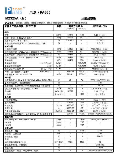
53752 52612
-
216-1 -
1006
139/157 2.5-3.5/6-8(干态)
0.27(干态) 1.5(干态)
介电常数 1MHz 损耗角 1MHz 体积电阻 表面电阻 介电强度 K20/P50 相对电弧径迹指数 CTI,试验溶液 A/ CTIM,试验溶液 B 燃烧特性
热变形温度,1.8Mpa 负荷(HDT A)/0.45Mpa 负荷(HDT B) ℃
75
75
250(干态)/250(干态)
最大使用温度,(短周期操作)
℃
-
-
225
温度指数,在 20000h/5000h 后拉伸强度下降 50%时 线性热膨胀系数,纵向/横向,(23-80)℃ 导热率 比热容 电性能
℃ 10-5/K
J MPa
53457 53455 53455 53444 53452
53443-1 2039-1
527 527 527 899 178 179/1eU 179/1eU 180/1A 6603-1 2039-1
8500/6000(干/湿) 150/110(干/湿) 3/4.5(干/湿) 3500(湿) 7500/(干/湿) 65/70(干/湿)/60(干) 13/17(干/湿) 11/17(干/湿)/-(干) 4/10(干/湿)/-(干) 190(干/湿)
1183 307
1.40(干态) 140
吸水率在 23℃水中,饱和
%
53495/1L
-
5.7-6.3
吸湿性在标准环境下 23℃/50%相对湿度,饱和 机械性能
%
-
-
1.2-1.6
拉伸弹性模量
PA66性能概述

PA66性能概述物化性能PA66,聚酰胺66或尼龙66。
PA66在聚酰胺材料中有较高的熔点。
它是一种半晶体-晶体材料。
PA66在较高温度也能保持较强的强度和刚度。
PA66在成型后仍然具有吸湿性,其程度主要取决于材料的组成、壁厚以及环境条件。
在产品设计时,一定要考虑吸湿性对几何稳定性的影响。
为了提高PA66的机械特性,经常加入各种各样的改性剂。
玻璃就是最常见的添加剂,有时为了提高抗冲击性还加入合成橡胶,如EPDM和SBR等。
PA66的粘性较低,因此流动性很好(但不如PA6)。
这个性质可以用来加工很薄的元件。
它的粘度对温度变化很敏感。
PA66的收缩率在1%~2%之间,加入玻璃纤维添加剂可以将收缩率降低到0.2%~1%。
收缩率在流程方向和与流程方向相垂直方向上的相异是较大的。
PA66对许多溶剂具有抗溶性,但对酸和其它一些氯化剂的抵抗力较弱。
注塑工艺干燥处理:如果加工前材料是密封的,那么就没有必要干燥。
然而,如果储存容器被打开,那么建议在85C的热空气中干燥处理。
如果湿度大于0.2%,还需要进行105C,12小时的真空干燥。
熔化温度:260~290C。
对玻璃添加剂的产品为275~280C。
熔化温度应避免高于300C。
模具温度:建议80C。
模具温度将影响结晶度,而结晶度将影响产品的物理特性。
对于薄壁塑件,如果使用低于40C的模具温度,则塑件的结晶度将随着时间而变化,为了保持塑件的几何稳定性,需要进行退火处理。
注射压力:通常在750~1250bar,取决于材料和产品设计。
注射速度:高速(对于增强型材料应稍低一些)。
流道和浇口:由于PA66的凝固时间很短,因此浇口的位置非常重要。
浇口孔径不要小于0.5*t(这里t为塑件厚度)。
如果使用热流道,浇口尺寸应比使用常规流道小一些,因为热流道能够帮助阻止材料过早凝固。
如果用潜入式浇口,浇口的最小直径应当是0.75mm。
典型用途PA66更广泛应用于汽车工业、仪器壳体以及其它需要有抗冲击性和高强度要求的产品。
PA66物性数据

PA66物性数据PA66(聚酰胺66)是一种高性能的工程塑料,具有优异的物理和化学性能。
以下是PA66的物性数据:1. 密度:PA66的密度为1.14-1.15g/cm³,具有较高的比重,使其在应用中具有较好的稳定性和抗震性能。
2. 熔融温度:PA66的熔融温度约为250-260℃,具有较高的熔融温度,使其适合于高温环境下的应用。
3. 拉伸强度:PA66的拉伸强度在60-80MPa之间,具有较高的强度,使其在结构件和零部件的创造中能够承受较大的力。
4. 弯曲强度:PA66的弯曲强度在90-120MPa之间,具有较高的强度,使其在受力较大的应用中具有良好的表现。
5. 弯曲模量:PA66的弯曲模量在2000-3000MPa之间,具有较高的刚度,使其在结构件的设计中能够提供稳定的支撑。
6. 热变形温度:PA66的热变形温度约为200-220℃,具有较高的热稳定性,使其在高温环境下保持较好的性能。
7. 热膨胀系数:PA66的线性热膨胀系数约为0.8-1.2×10^-4/℃,具有较低的热膨胀性,使其在温度变化时能够保持较好的尺寸稳定性。
8. 水吸收率:PA66的水吸收率约为2-3%,具有较低的吸水性,使其在潮湿环境下仍能保持较好的性能。
9. 绝缘性能:PA66具有良好的绝缘性能,使其在电气和电子领域中得到广泛应用。
10. 耐化学性:PA66具有良好的耐化学性,能够反抗多种化学物质的侵蚀,适合于要求耐腐蚀性能的应用。
总结:PA66是一种具有优异物理和化学性能的工程塑料,具有较高的密度、熔融温度、拉伸强度、弯曲强度和弯曲模量。
它具有较高的热稳定性和较低的热膨胀系数,能够在高温环境下保持较好的性能和尺寸稳定性。
此外,PA66具有良好的绝缘性能和耐化学性,使其在电气、电子和化工等领域得到广泛应用。
PA66物性数据
PA66物性数据PA66物性数据是指聚酰胺66(Polyamide 66)的物理性质和化学性质的数据。
聚酰胺66是一种常见的工程塑料,具有优异的力学性能、耐热性、耐化学腐蚀性和电绝缘性能,被广泛应用于汽车、电子、纺织品、电器等领域。
以下是PA66的一些常见物性数据:1. 密度:PA66的密度普通在1.13-1.15 g/cm³之间,具体数值会根据添加剂和加工工艺的不同而有所变化。
2. 熔点:PA66的熔点约为255-265℃,可以通过热差示扫描量热仪(DSC)等测试方法进行测定。
3. 玻璃化转变温度:PA66的玻璃化转变温度通常在40-50℃之间,该温度以下,聚合物呈玻璃态,以上则呈弹性态。
4. 拉伸强度:PA66具有较高的拉伸强度,通常在60-80 MPa之间,该数值可以通过拉伸试验获得。
5. 弯曲强度:PA66的弯曲强度普通在80-100 MPa之间,该数值可以通过弯曲试验获得。
6. 弯曲模量:PA66的弯曲模量约为2000-3000 MPa,该数值可以用来衡量材料的刚度和变形能力。
7. 冲击强度:PA66具有较高的冲击强度,通常在10-20 kJ/m²之间,该数值可以通过冲击试验获得。
8. 热膨胀系数:PA66的热膨胀系数普通在70-90×10^-6/℃之间,该数值可以用来评估材料在温度变化时的尺寸稳定性。
9. 热导率:PA66的热导率约为0.2-0.3 W/(m·K),该数值可以用来描述材料传导热量的能力。
10. 水吸湿性:PA66具有一定的水吸湿性,通常在1-3%之间,该数值可以通过浸泡试验获得。
11. 耐化学腐蚀性:PA66对许多化学物质具有良好的耐腐蚀性,但对强酸、强碱和氧化剂等具有腐蚀性的物质可能会受到影响。
以上是PA66物性数据的一些常见指标,这些数据可以匡助工程师和设计师选择合适的材料,并进行产品设计和工艺优化。
需要注意的是,不同厂家生产的PA66可能会有稍微的差异,因此在具体应用中还需要参考厂家提供的技术数据和实际测试结果。
工程塑料的高速拉伸测试
3】姚贵升车身用钢板的抗碰擅性能[J】汽车工艺与材料.2∞6
(8){15
4]张必文.何磋新高速拉伸试验机快遘加葡方法评连【J]试验 技术与试验机.1988(6):2
工程塑料的高速拉伸测试
作者: 作者单位:
陈广强, 杜砚文, 张淋图 上海金玺实验室有限公司,上海 201700
本文链接:/Conference_7591649.aspx
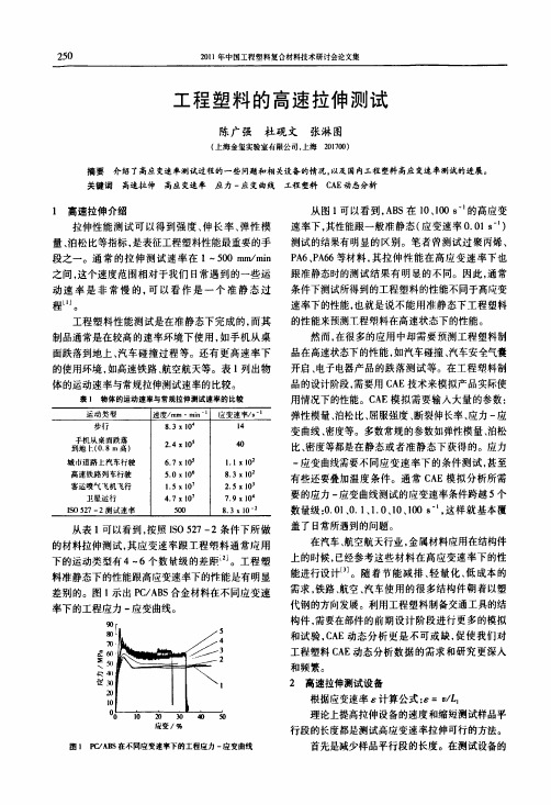
提高应变速率的另外一个途径就是提高测试设 备的拉伸速度。现有的万能试验机都是电机驱动, 通过丝杠减速。通过调整丝杠的减速比例,万能试 验机理论上可以做到很高的拉伸速度。但实际存在 一个问题,就是拉伸过程开始阶段拉伸速度从0达 到设定速度是需要一段时间的。图2就是万能试验 机的一个拉伸测试过程中横梁速率和应力对应于时 间的曲线。测试过程设定的横梁速率是1800 mm/ rain,样品平行段尺寸是30 mm.计算出应变速率是 1 8。横粱从0提高到1800 mm/min所用时间大 概是0 1s,如果是更高的速率别需要更多的时间。 在1800 mm/min的横梁位移速率下,整个拉伸测试 过程大概3 s完成.弹性段的测试时间小于0 1 s。 相对于整个测试过程,0 1 s只是很短的一段时间, 但是在这个时间段内样品已经完成了弹性形变过 程。而对于10、100 s。1的测试,整个测试过程都少 于0 l s。也就是说,即使是现有的万能试验机的横 粱速度能够达到高应变速率下的要求,测试过程在 达到设定的速率之前已经结束,实际的测试结果并 不是在设定速率之下完成的。
60 50
l 40
、30 理∞
10
时间/一 圉2[800mm/min拉抻速率T建率一时问曲线
和应力一时闻曲线№较
对于如何保证拉伸测试过程的高速率,张兴文 等”1有详细的总结:(1)火药爆炸冲击式;(2)气一 气加荷式;(3)飞轮储能式;(4)气一液加荷式;(5) 电液伺服式。对于小于1000 8“的应变速率,使用 电液伺服式的设备较成熟。图3是电液伺服式高速 拉伸设备的原理示意图。
塑料粒子pa66拉伸强度
塑料粒子pa66拉伸强度塑料粒子PA66是一种常用的工程塑料,具有优异的力学性能和热稳定性。
拉伸强度是衡量材料抗拉能力的重要指标之一,也是评价PA66材料性能的重要参数。
本文将从PA66的结构特点、加工工艺和材料性能等方面,详细探讨PA66的拉伸强度。
PA66是一种聚酰胺类塑料,由尼龙6和尼龙66两种单体通过缩聚反应而成。
其分子链中的酰胺基团和酰胺键使得PA66具有较高的结晶度和强度。
在拉伸过程中,PA66的分子链能够在外力作用下发生拉伸和变形,形成分子链的取向和排列,从而提高材料的拉伸强度。
PA66的加工工艺对其拉伸强度也有着重要影响。
一般来说,通过熔融挤出、注塑成型等工艺可以得到具有较高拉伸强度的PA66制品。
在挤出过程中,塑料粒子经过熔融加热后,通过挤出机的螺杆推进,形成连续的塑料流动,最终形成所需的产品形状。
由于挤出过程中的拉伸和冷却,使得PA66的分子链排列更加有序,从而提高了材料的拉伸强度。
PA66的拉伸强度还受到材料的结晶度、玻璃化转变温度等因素的影响。
结晶度是指材料中结晶区域的百分比,结晶度越高,材料的拉伸强度越大。
而玻璃化转变温度是指材料在加热过程中由玻璃态转变为橡胶态的温度,高玻璃化转变温度意味着材料在高温下仍能保持较高的拉伸强度。
PA66的拉伸强度还受到外界条件的影响,如温度、湿度和应变速率等。
一般来说,温度升高会使PA66的拉伸强度下降,因为高温会导致材料分子链的热运动增加,结晶度降低。
湿度对PA66的影响较小,但在高温高湿环境下,PA66的拉伸强度会明显下降。
此外,应变速率越大,PA66的拉伸强度也会相应增加。
塑料粒子PA66的拉伸强度受到多种因素的影响,包括材料的结构特点、加工工艺、结晶度、玻璃化转变温度以及外界条件等。
只有充分了解这些影响因素,并进行合理的材料选择和工艺控制,才能获得具有良好拉伸强度的PA66制品。
在实际应用中,我们可以根据具体需求,通过调整材料配方、加工参数和工艺条件等,来提高PA66的拉伸强度,以满足不同领域的使用要求。
pa66检测标准
pa66检测标准
PA66的检测标准主要包括以下几个方面:
1.化学成分:PA66的化学成分要求可能因不同的标准而
有所不同,常见的化学成分包括己内酰胺
(Hexamethylenediamine)和己二酸(Adipic Acid)。
2.物理性能:PA66的物理性能标准包括抗张强度、弹性
模量、冲击强度、硬度等。
这些标准可以根据不同的应用需求进行调整。
3.热性能:PA66的热性能标准包括热变形温度、热稳定
性、热膨胀系数等。
这些标准可以用于评估材料的热稳定性和耐高温性能。
在具体的检测过程中,还需要遵循相应的检测标准和规范,例如GB/T 19466.1-2004塑料差示扫描量热法(DSC)第1部分:通则和GB/T 19466.3—2004塑料差示扫描量热法(DSC)第3部分∶熔融和结晶温度及热焓的测定等。
以上信息仅供参考,如需了解更多信息,建议咨询专业人士。
pa66尼龙隔热条检测标准
pa66尼龙隔热条检测标准PA66尼龙隔热条是一种常用于隔热材料的产物,主要用于工业和建筑领域中的保温和隔热应用。
为了确保产品质量和性能的可靠性,针对PA66尼龙隔热条的检测标准是很重要的。
以下是一些相关参考内容,描述了PA66尼龙隔热条的常见检测方法和标准。
1. 外观检查:包括表面平整度、尺寸和形状等方面的检查。
外观检查是对尺寸、形状、表面质量和颜色等外观特征进行的初步质量判断。
其中,表面平整度是指尼龙隔热条表面是否平整、无明显凹凸点,尺寸和形状是指尺寸是否符合规定的要求。
2. 密度测定:采用测量尼龙隔热条的质量和体积,通过质量与体积的比值来计算密度。
密度是材料的一个重要性能参数,对于尼龙隔热条来说,其密度直接关系到隔热性能的优劣。
3. 力学性能测试:包括拉伸强度、断裂伸长率、弯曲强度等方面的测试。
拉伸强度和断裂伸长率是衡量尼龙隔热条的强度和韧性的指标,而弯曲强度则反映了材料对扭曲的能力。
4. 热性能测试:主要包括热变形温度、热膨胀系数等方面的测定。
热变形温度是指尼龙隔热条在一定条件下发生形变的温度,热膨胀系数则是材料在温度变化时长度变化的比例。
5. 导热系数测定:导热系数是衡量材料导热能力的指标,可以通过热传导实验仪器进行测定。
对于尼龙隔热条来说,导热系数直接影响其隔热效果,因此该指标的检测非常重要。
6. 耐候性能测试:包括耐气候老化、耐紫外线照射等方面的测试。
尼龙隔热条通常需要长时间使用在室外环境中,因此其耐候性能是评价其使用寿命的重要指标。
以上是PA66尼龙隔热条常见的检测方法和标准的一些参考内容。
可能有一些专业检测标准没有详细描述,需要根据具体的实际情况来进行选择和应用。
在进行检测时,应按照相关的标准和规范操作,确保测试结果的准确性和可靠性,从而保证PA66尼龙隔热条的质量和性能。
PA66拉伸强度的不确定度评定 (已阅20180601)

不确定度评定报告PA66拉伸强度评定人:日期:审核人:日期:1.概述………………………………………………………………1.2.建立数学模型 (1)3.引入不确定度的分量及分量的评定 (1)3.1厚度测量不确定度的评定 (2)3.2宽度测量不确定度的评定 (3)3.3 面积测量不确定度的评定 (4)3.4拉力试验机不确定度的评定 (4)3.5 重复测量不确定度的评定 (4)3.6 温湿度变化及数值修约引起的不确定度评定 (5)4.合成不确定度的评定 (5)5.扩展不确定度评定 (6)6.测量不确定度报告及表示 (6)根据“IOS/IEC 17025”要求,对PA66拉伸强度测定不确定度进行评定,所检测条件及过程如下:1.1 测量过程:采用电子拉力试验机对塑料试样拉伸强度进行测量 1.2 测量依据:GB/T 2567-20081.3 测量环境:(23℃±2)℃,相对湿度55%。
1.4 测量对象:抽取一份样品,注塑成哑铃状试样,长150mm 、宽10mm 、厚4mm 。
1.5 测量设备:电子拉力试验机,测量范围(0~5000)N ,准确度等级1.0级。
2. 建立数学模型 拉伸强度A F =σ式中:---F 拉断力---A 工作部分初始截面积 3. 标准不确定度评定经分析,树脂浇注体拉伸强度性能测量不确定度的主要来源是: 试样尺寸(厚度、宽度)测量引入的不确定度; 拉力试验机引入的不确定度; 重复测量引入的不确定度; 温湿度变化引入的不确定度 数字修约引入的不确定度。
3.1 厚度测量不确定度的评定(1)厚度重复测量带来的不确定度,重复10次测量厚度的结果如下表:n 1 2 3 4 5 6 7 8 9 10h/mm 3.94 3.93 3.93 3.94 3.93 3.95 3.95 3.94 3.94 3.93表中:n—测量次数,h—试样厚度得出样本算术平均值=3.938mm根据贝塞尔公式得出=0.0079mm试样厚度重复测量带来的标准不确定度为:u1=s=0.0079mm(2)数显卡尺带来的标准不确定度按B类方法进行评定,经查校准证书数显卡尺的不确定度为:u2=0.005mm(3)厚度测量带来的总的标准不确定度:=0.009mm相对标准不确定度为:=0.0023=0.23%3.2 宽度测量不确定度的评定(1)宽度重复测量带来的不确定度,重复10次测量宽度的结果如下表:n 1 2 3 4 5 6 7 8 9 10b/mm 9.94 10.03 10.03 9.98 10.02 9.95 9.95 9.94 10.04 10.03 表中:n—测量次数,b—试样宽度得出样本算术平均值=9.991mm根据贝塞尔公式得出=0.0428mm试样宽度重复测量带来的标准不确定度为:u1=s=0.0428mm相对标准不确定度为:=0.0043=0.43%3.3 面积测量不确定度的评定试样工作面积为=A⨯WH因为试样宽度和厚度的测量相互独立,所以面积测量带来的相对标准不确定度为:=0.49%3.4拉力试验机不确定度的评定拉力试验机带来的标准不确定度按B类方法进行评定,经查校准证书拉力试验机的不确定度为:u rL=0.2%3.5重复测量不确定度的评定(1)测量带来的不确定度,重复10次测量的结果如下表:n12345678910σ/MPa 38.11 35.51 38.95 38.54 36.49 35.49 38.64 37.69 37.54 36.73表中:n —测量次数,σ—拉伸强度 得出样本算术平均值=37.369MPa根据贝塞尔公式得出 =1.262 MPa拉伸强度重复测量带来的标准不确定度为: u σ=s=1.262 MPa相对标准不确定度为:=0.0338=3.38%3.6温湿度变化及数值修约引起的不确定度评定温湿度变化及数值修约引起的不确定度可忽略不计。
pa66检测标准
pa66检测标准PA66检测标准是指对聚酰胺66(Polyamide 66,简称PA66)进行检测时所采用的标准和方法。
PA66是一种常见的高性能工程塑料,具有优良的耐热性、耐候性和机械性能,广泛应用于汽车、电子电器、纺织、电力等领域。
为了确保PA66产品的质量和安全性,进行相关的检测是必要的。
下面是一些常见的PA66检测标准的相关参考内容:1. 物理性能测试标准:- GB/T 1040-2006《塑料拉伸性能试验方法》:包括拉伸强度、断裂伸长率、弯曲模量等。
- ISO 178:《塑料断裂扫描电镜显微镜检验判断抗冲击性联合加载的判定》:用于评估PA66的抗冲击性能。
- GB/T 9341-2008《玻璃纤维增强塑料组成材料性能的测定》:用于进行PA66玻璃纤维增强复合材料的力学性能测试。
2. 热性能测试标准:- GB/T 1633-2000《塑料电气绝缘材料燃烧性能通用试验方法》:用于评估PA66的燃烧性能,以确定其在火灾中的安全性。
- GB/T 25052-2010《高性能工程塑料水分测定》:用于测定PA66中的水分含量,以评估其对热性能的影响。
- GB/T 13531-2005《塑料玻璃转移温度的测定》:用于测定PA66的玻璃转移温度,以评估其耐热性能。
3. 化学性能测试标准:- GB/T 8806-2008《塑料挥发性及可溶性物浸出的确定》:用于测定PA66中挥发性有机物和可溶性物的含量,以评估其化学稳定性。
- GB/T 2951.3-2008《绝缘和护套材料灭弧性聚苯基酯、聚酰胺和聚酰胺-聚酰胺共聚物》:用于评估PA66在高温下的耐化学品性能。
- GB/T 9342-2008《树脂基复合材料基体树脂的分析试验方法》:用于检测PA66复合材料中树脂的含量和组分。
4. 环境性能测试标准:- GB/T 2423.17-2008《电工电子产品湿热试验试验Ka:热(H)》:用于评估PA66材料在高湿高温环境下的稳定性和耐久性。
拉伸性能测试
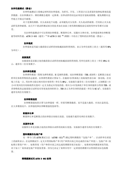
拉伸性能测试(静态)拉伸性能测试主要确定材料的拉伸强度,为研究、开发、工程设计以及质量控制和标准规范提供数据。
在拉伸测试中,薄的薄膜会遇到一定困难。
拉伸试样的切边必须没有划痕或裂缝,避免薄膜从这些地方开始过早破裂。
对于更薄的薄膜,夹头表面是个问题。
必须避免夹头发滑、夹头处试样破裂。
任何防止夹头处试样发滑和破裂,而且不干扰试样测试部分的技术如在表面上使用薄的橡胶涂层或使用纱布等都可以接受。
从拉伸性能测试中可以得到拉伸模量、断裂伸长率、屈服应力和应变、拉伸强度和拉伸断裂能等材料性能。
ASTM D 638 (通用)[4]和ASTM D 882 [5](薄膜)中给出了塑料的拉伸性能(静态)。
拉伸强度拉伸强度是用最大载荷除以试样的初始截面面积得到的,表示为单位面积上的力(通常用MPa 为单位)。
屈服强度屈服强度是屈服点处的载荷除以试样的初始截面面积得到的.用单位面积上的力(单位MPa)表示,通常有三位有效数字。
拉伸弹性模量拉伸弹性模量(简称为弹性模量,E)是刚性指数,而拉伸断裂能(TEB,或韧性)是断裂点处试样单位体积所吸收的总能量。
拉伸弹性模量计算如下:在载荷-拉伸曲线上初始线性部分画一条切线,在切线上任选一点,用拉伸力除以相应的应变即得(单位为MPa),实验报告通常有三位有效数字。
正割模量(应力-应变间没有初始线性比值时)定义为指定应变处的值。
将应力-应变曲线下单位体积能积分得到TEB,或者将吸收的总能量除以试样原有厚度处的体积积分。
TEB表示为单位体积的能量(单位为MJ/m3),实验报告通常有两位有效数字。
拉伸断裂强度拉伸断裂强度的计算与拉伸强度一样,但要用断裂载荷,而不是最大载荷。
应该注意的是,在大多数情况中,拉伸强度和拉伸断裂强度值相等。
断裂伸长率断裂伸长率是断裂点的拉伸除以初始长度值。
实验报告通常有两位有效数字。
屈服伸长率屈服伸长率是屈服点处的拉伸除以试样的初始长度值,实验报告通常有两位有效数字。
PA66 A3X2G5
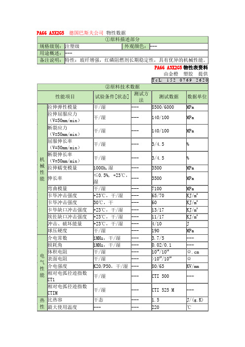
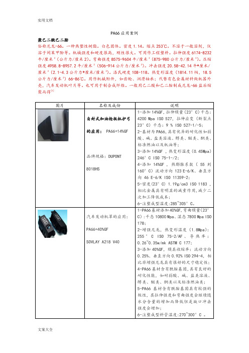
PA66 A3X2G5德国巴斯夫公司物性数据①原料描述部分规格级别:注塑级外观颜色:---用途概述:---备注说明:特性:玻纤增强,红磷阻燃剂长期稳定性,具有优异的机械性能。
PA66 A3X2G5物性表资料由金橙塑胶提供T e L: 1 5 2 0 7 6 9 2 6 2 0②原料技术数据性能项目试验条件[状态] 测试方法测试数据数据单位机械性能拉伸弹性模量干/湿--- 8500/6000 MPa 拉伸屈服应力(V=50mm/min)干/湿--- 140/100 MPa 断裂应力(V=50mm/min)干/湿--- 140/100 MPa 屈服伸长率(V=50mm/min)干/湿--- 3/4.5 % 断裂伸长率(V=50mm/min)干/湿--- 3/4.5 % 拉伸蠕变模量1000h,湿--- 3500 MPa 伸长率≤0.5%, +23℃,湿--- 3500 MPa 弯曲模量干/湿--- 7100 MPa 卡毕冲击强度+23℃,干/湿--- 65/70 KJ/m2卡毕冲击强度30℃,干--- 60 KJ/m2卡毕缺口冲击强度+23℃,干/湿--- 13/17 KJ/m2埃佐缺口冲击强度+23℃,干/湿--- 11/17 KJ/m2冲击、破坏能量+23℃,干/湿--- 4/10 J 球压硬度干/湿--- 190 MPa电气性能介电常数1MHz,干/湿--- 3.7/5 --- 损耗角1MHz,干/湿--- 0.02/0.1 --- 体积电阻干/湿--- 1015/1012Ω.cm 表面电阻干/湿--- >1013/1010Ω介电强度K20/P50,干/湿--- 80/65 KV/mm 相对电弧径迹指数CT1干/湿--- CTI 500 --- 相对电弧径迹指数CTIM干/湿--- CTI 525 M ---热性比热容干态--- 1.5 J/(g.K) 最大使用温度--- --- 220 ℃能温度指数在20000h/5000h,后拉伸强度下降50%时--- 139/157 ℃线性热膨胀系数(23-80)℃,干态--- 2.5-3.5/6-8 10-5/K导热率干态--- 0.27 W/(m.K)热变形温度1.8MPa负荷,干态--- 250 ℃热变形温度0.45MPa负荷,干态--- 250 ℃如果对PA66 A3X2G5方面还有什么疑问,请与我们详谈!尼龙66为聚己二酰己二胺,工业简称PA66。
pa66测试标准
pa66测试标准
PA66的测试标准主要包括以下几个方面:
1.熔点范围:PA66的熔点范围通常为220-250℃。
在测试中,会通过热分析方法测量PA66的熔点范围,以评估其热稳定性和加工性能。
2.密度:PA66的密度通常为1.14-1.15g/cm³。
在测试中,会通过测量样品的体积和质量来计算密度,以评估其物理性能和加工性能。
3.吸水率:PA66的吸水率通常较低,一般在0.3%以下。
在测试中,会通过测量样品在水中浸泡后的重量变化来计算吸水率,以评估其耐候性和尺寸稳定性。
4.拉伸强度:PA66的拉伸强度通常较高,一般在
80-100MPa之间。
在测试中,会通过拉伸试验机测量样品的拉伸强度和伸长率,以评估其力学性能和加工性能。
5.弯曲强度:PA66的弯曲强度通常较高,一般在
100-120MPa之间。
在测试中,会通过弯曲试验机测量样品的弯曲强度和挠曲变形量,以评估其力学性能和加工性能。
除了以上几个方面的测试标准外,PA66还可能需要进行其他方面的测试,如耐化学腐蚀性、耐磨性、耐候性等。
这些测试标准需要根据具体的应用需求和产品要求来确定。
PA66应用案例
PA66应用案例
聚己二酰己二胺
俗称尼龙-66。
一种热塑性树脂。
白色固体。
密度1.14。
熔点253℃。
不溶于一般溶剂,仅溶于间苯甲酚等。
机械强度和硬度很高,刚性很大。
可用作工程塑料。
拉伸强度6174-8232牛/厘米2(公斤力/厘米2)。
弯曲强度8575-9604牛/厘米2(875-980公斤力/厘米2)。
压缩强度4958.8-8957.2牛/厘米2(506-914公斤力/厘米2)。
冲击强度20.58-42.14牛*厘米/厘米2(2.1-4.3公斤力*厘米/厘米2)。
洛氏硬度108-118。
热变形温度(1814.11帕,18.5公斤力/厘米2)66-86℃。
用作机械附件,如齿轮、润滑轴承;代替有色金属材料做机器外壳,汽车发动机叶片等。
也可用于制合成纤维。
一般用己二酸和己二胺制成尼龙-66盐后缩聚而得[1]。
- 1、下载文档前请自行甄别文档内容的完整性,平台不提供额外的编辑、内容补充、找答案等附加服务。
- 2、"仅部分预览"的文档,不可在线预览部分如存在完整性等问题,可反馈申请退款(可完整预览的文档不适用该条件!)。
- 3、如文档侵犯您的权益,请联系客服反馈,我们会尽快为您处理(人工客服工作时间:9:00-18:30)。
Tensile Deformation of Electrospun Nylon-6,6NanofibersE.ZUSSMAN,1M.BURMAN,1A.L.YARIN,1R.KHALFIN,2Y.COHEN21Faculty of Mechanical Engineering,Technion,Israel Institute of Technology,Haifa32000,Israel2Department of Chemical Engineering,Technion,Israel Institute of Technology,Haifa32000,IsraelReceived25July2005;revised25December2005;accepted24February2006DOI:10.1002/polb.20803Published online in Wiley InterScience().ABSTRACT:Nylon-6,6nanofibers were electrospun at an elongation rate of the orderof1000sÀ1and a cross-sectional area reduction of the order of0.33Â105.The influ-ence of these process peculiarities on the intrinsic structure and mechanical proper-ties of the electrospun nanofibers is studied in the present work.Individual electro-spun nanofibers with an average diameter of550nm were collected at take-up veloc-ities of5and20m/s and subsequently tested to assess their overall stress–straincharacteristics;the testing included an evaluation of Young’s modulus and the nano-fibers’mechanical strength.The results for the as-spun nanofibers were compared tothe stress–strain characteristics of the melt-extruded microfibers,which underwentpostprocessing.For the nanofibers that were collected at5m/s the average elonga-tion-at-break was66%,the mechanical strength was110MPa,and Young’s moduluswas453MPa,for take-up velocity of20m/s—61%,150and950MPa,respectively.The nanofibers displayed a-crystalline phase(with triclinic cell structure).V C2006WileyPeriodicals,Inc.J Polym Sci Part B:Polym Phys44:1482–1489,2006Keywords:electrospinning;nanofiber;nylon-6,6;tensile stress;Young’s modulusINTRODUCTIONNanomaterials can possess different mechanical properties than those of the bulk materials from which they were derived.This is perhaps due to different processing conditions that can affect the material’s structure or to the characteristic length scale,that is,confinement arrangements. For electrospun nanofibers made from polymer solutions with a typical diameter ranging from 20to1000nm,the extreme processing condi-tions can affect the macromolecular conforma-tion,the nanofiber structure,as well as the me-chanical characteristics.Projected uses for such nanofibers includefilter media and catalyst sup-ports,drug delivery carriers,tissue scaffolds,so-lar sails,reinforcing elements in composite ma-terials,nanosensors,and airborne structures.1–6 In many of these applications,the mechanical characteristics of electrospun nanofibers are of utmost importance.Evaluating these character-istics is the goal of the present work.A characteristic feature of the electrospinning process is the extremely rapid formation of the nanofiber structure,which is on a millisecond scale and can apparently promote the nucleation and growth of the polymer crystallites.Other no-table features of electrospinning are a huge mate-rial elongation rate of the order of1000sÀ1,and a cross-sectional area reduction of the order of 105.7,8These unusual characteristics of the elec-trospinning process have been shown to affect the orientation of the structural elements within the fiber,9–12which,in turn,is believed to have a direct impact on the mechanical properties of the nanofibers.Apparently,structural orientation and crystallinity inCorrespondence to: E.Zussman(E-mail:meeyal@tx.technion.c.il)Journal of Polymer Science:Part B:Polymer Physics,Vol.44,1482–1489(2006)V C2006Wiley Periodicals,Inc.14821.29governing parameters of the electrospinning pro-cess,and the nature of the polymer solutions(their rheological behavior,surface charge density,and solvent characteristics).13It was expected that structural characteris-tics would affect tensile mechanical properties, and studies to characterize the mechanical properties of individual electrospun nanofibers have already been performed.Tan et al.14con-ducted tensile tests of individual poly(e-capro-lactone),PCL,electrospun nanofibers.When comparing the results to gravity-spun PCLfi-bers,they found that the modulus and maximal tensile stress of the electrospun nanofibers were larger.In another work,Tan et al.15found that the tensile modulus of an individual elec-trospun PEO nanofiber is of the same order of magnitude as the corresponding bulk material. Inai et al.16investigated the mechanical prop-erties of as-spun poly(L-lactic acid)PLLA nano-fibers.The tensile strength of these nanofibers was close to that of the melt-spun PLLAfibers. In contrast,the tensile modulus and the strain-at-break of the electrospun nanofibers were lower than those of the melt-spunfibers.A higher tensile modulus and strength,but lower strain-at-break were obtained by increasing the take-up velocity.For stretched PEO nanofibers collected using a rotating wheel,multiple neck-ing and(in certain cases)fibrillar patterns resembling crazing in the necked regions have been observed;this is probably due to stretch-ing by the wheel.17The crazing was attributed to the formation of polymer crystals of the shish-kebab type.11,17,18The aim of the present work is to study the intrinsic structure and mechanical properties of individual nylon-6,6(PA66)electrospun nanofib-ers.The individual nanofibers were mounted between the tip of an AFM cantilever and a stainless steel wire.The tensile stress–strain curves of the individual nanofibers were calcu-lated from the force-displacement curve of the AFM cantilever as it was bent.The structure of the as-spun nanofibers was analyzed by means of wide-angle X-ray(WAXD)and small-angle X-ray scattering(SAXS).The paper is organized as follows:in the experimental section we de-scribe the material preparation,the fabrication technique for the nanofiber specimens,and the experimental design.In the results and discus-sion section we present and discuss the essential results of the tensile tests.The conclusions are presentedfinally.EXPERIMENTALPA66pellets were obtained from Nilit,Israel. The pellets were dissolved in formic acid to yield a20wt%solution.All reagents were used with-out further purification.The polymer solution was electrospun from a5mL syringe with a hypo-dermic needle(inner diameter of0.1mm)and with aflow rate of5mL/h(a Harvard PHD 2000syringe pump was used).A copper elec-trode was placed in the polymer solution and the latter was electrospun onto the sharp edge of a grounded collector disk19(cf.the work of Theron et al.for additional details),where the aligned solidified nanofibers were collected.The strength of the electrostaticfield was1.7kV/cm with a potential of30kV.The linear speed of the edge of the disk collector was V¼5,or 20m/s.All the experiments were performed at ambient temperature(about258C)in air with a relative humidity of$40%.A forkedfiber holder made of aluminum foil was attached to the col-lector disk edge.As the electrospun nanofibers reached the disk,they were wound around the edge and aligned on thefiber holder.The nano-fibers were stored in vacuum(10À2Torr)for 24h before the tensile test experiments were conducted.The characterization of the nanofibers was done using a HRSEM(High Resolution SEM, Leo Gemini)operating at an accelerating voltage of3kV and a current of120pA.The nanofibers were placed on a silicon wafer for observation. Wide-angle X-ray(WAXS)and small-angle X-ray scattering(SAXS)were performed using a small-angle diffractometer(Bruker AXS Nanostar,tube: KFF CU2K-90)with Cu K a radiation,pinhole col-limation(that produced a100l m-diameter beam), and a10Â10cm2two-dimensional position-sensi-tive wire detector that was positioned at6.8cm (WAXS)and65.05cm(SAXS)behind the exam-ined sample.The X-ray beam was directed par-allel to the normal of thefiber bundle,which was detached from the edge of the collector disk. Therefore,the beam was perpendicular to the winding direction of the nanofibers.To perform the tensile tests,an individual electrospun nanofiber was removed from the forkedfiber holder.One end was mounted to the tip of an AFM cantilever(that served as a force-sensing element)and the other end to the etched tip of a stainless steel wire(that served as a pulling element20,21[cf.Refs.20and21for additional details on the measurement technique]).TENSILE PROPERTIES OF PA66ELECTROSPUN NANOFIBERS1483Journal of Polymer Science:Part B:Polymer PhysicsDOI10.1002/polbThe nanofiber ends were secured at these posi-tions with epoxy glue (Attex no.27,purchasedfrom Loctite).The AFM cantilevers were pur-chased from Mikromasch (series NSC38,NSC12,and NSC36).The cantilevers were considered as the Euler–Bernoulli beams of a rectangular cross-section with b and h being the width and thickness,and the length L being more than 5Áb .Since in the present case the cantilever deflection angles were always smaller than 108,the general solution for a clamped cantilever transversally loaded at the free end (tip)22reduces toP ¼K e dð1Þwhere P is the applied force acting perpendicu-lar to the cantilever at the tip,d is the resulting tip displacement and the elastic constant K e ¼3EI/L 3.In this equation,I is the cross-sectional moment of inertia and E is Young’s modulus.The first fundamental eigenfrequency of the cantilever is given by Timoshenko 23x ¼1:8752½EI =q S 1=2=L 2ð2Þwhere q is the cantilever density (q ¼2.3g/cm 3in the present case)and S ¼b Áh the cross-sec-tional ing,eq 2the expression for K e becomesK e ¼0:2427q bhL x 2ð3Þwhere 3/1.8754¼0.2427.This expression was used by Sader et al.in his work 24and in the present work.Each cantilever’s first eigenfrequency,x ,was found using a vibrometer (Polytec OFV 3001)in vacuum,and then K e was calculated as per eq 3.The results are presented in Table 1.Note that the value of x could also have been calculated using the expression for the moment of inertia I ¼bh 3/12and a value of E .However,as E is not known with a high degree of accuracy,better results can be achieved using direct measure-ment of x as was done in the present work.For the tensile test,the cantilever end was loaded normally to its neutral axis at the tip via the attached nanofiber pulled by a wire at a lin-ear velocity of 4l m/s.The other end of the can-tilever was clamped.The deflection,d ,of the AFM cantilever was observed using an Olympus BX51microscope with 500Âand 1000Âmagnifi-cations (long distance focal length objective),T a b l e 1.E x p e r i m e n t a l R e s u l t s f o r t h e E l a s t i c C o n s t a n t (K e )O b t a i n e d f o r t h e A F M C a n t i l e v e r sK e (N /m )M o d e l :N S C 38/A I /15K e (N /m )M o d e l :N S C 12/A I /15K e (N /m )M o d e l :N S C 36/A I /15b Âh ÂL (l m )35Â1Â300b Âh ÂL (l m )35Â1Â350b Âh ÂL (l m )35Â1Â250b Âh ÂL (l m )35Â2Â300b Âh ÂL (l m )35Â2Â350b Âh ÂL (l m )35Â2Â250b Âh ÂL (l m )35Â1Â110b Âh ÂL (l m )35Â1Â90b Âh ÂL (l m )35Â1Â1300.0720.0510.1250.4510.2840.7960.6521.1770.4140.0550.040.1710.3690.3270.6210.7101.2320.4680.0990.0670.1040.5210.2260.9170.5931.0900.5131484ZUSSMAN ET AL.Journal of Polymer Science:Part B:Polymer PhysicsDOI 10.1002/polbequipped with a CCD camera (Olympus DP12).A series of images taken during a tensile test is shown in Figure 1.The gauge length of the fiber,L f ,was defined as its length between the apex of the AFM tip and the tip of the stainless steel wire.The length change,d L f ,as a function of the applied load was measured,and the strain was obtained from dL f =L f 0,where L f 0is the initial length of the nanofiber.This resultedin a nominal strain rate of _e %8Â10À2s À1.RESULTS AND DISCUSSIONFigure 2shows a SEM micrograph of the elec-trospun PA66nanofibers.The individual fibersare observed to have uniform cross sections with an average diameter of 550nm (with the stand-ard deviation,SD ¼120nm)for the take-upwheel velocity of 20m/s,and a larger diameter of 570nm (SD ¼40nm)for the take-up velocity of 5m/s.The X-ray diffraction patterns (WAXS)of bundles of aligned electrospun nanofibers pro-duced at 5and 20m/s are shown in Figure 3(a,b)respectively.The nanofibers exhibited four reflections corresponding to,001,002,and 100spacing and a [010]/[110]doublet for the a -crys-talline form of PA66(triclinic structure,a ¼4.9A˚,b ¼5.4A ˚,and c ¼17.2A ˚,a ¼48.58,b ¼778,and c ¼63.58).25,26The diffracted intensity of the nanofibers collected at 20m/s [Fig.3(b)]manifests itself in the form of equatorial arcs indicating a preferred axial orientation of nylon crystallites inside the fiber,wherein the normals to the ac and bc planes are perpendicular to the fiber axis.In contrast,crystallites in the nano-fibers electrospun at the lower take-up velocity of 5m/s manifest themselves by rather uniform diffraction rings [Fig.3(a)].Consider once more Figure 3(b),which corresponds to the higher take-up velocity of 20m/s.The equatorial dif-fraction arcs are not fully separated,but are instead merged into a single arc that resembles that of PA66,which has been rapidly quenched from melt.26It is useful to compare these find-ings to those of Hsiao et al.27in which the dif-fraction patterns of highly oriented PA66were found to be much sharper when examining the melt-drawn fibers produced at room tempera-ture with draw ratios of 1.01–1.37at a drawing speed of 0.05m/s.The azimuthal scans of the individual diffraction rings in Figure 3(a,b)for the [010]/[110]doublet are shown in Figure 3(c,d).A quantitative orientation factor,f ¼90Àu 090(u 0is Figure 1.A series of images taken during a tensile test up to break of an electro-spun PA66nanofiber.The fiber was attached to the tip of an AFM cantilever and pulled transversally by a stainless steel wire.The deflection of the cantilever,d ,is proportional to the applied force and was measured throughout the tensiletest.Figure 2.SEM micrograph of the electrospun PA66nanofibers.TENSILE PROPERTIES OF PA66ELECTROSPUN NANOFIBERS 1485Journal of Polymer Science:Part B:Polymer Physics DOI 10.1002/polbthe half-width of a reflected peak at half its height),of polymer crystallites can be calculated from the azimuthal scans.This yields the orienta-tion factor of f ¼0.8for V ¼20m/s and f ¼0.58for V ¼5m/s.A two-dimensional SAXS image of the electro-spun nanofibers is shown in Figure 4.The image does not reveal any lamellar superstruc-ture (a structure on a scale larger than the unit cell with a repeating long period).The elliptical shape of the diffuse small-angle scattering indi-cates elongated nanostructures,possibly nanofi-brils or voids between them.Melt-drawn PA66fibers exhibit a long period of 100A˚.26There-fore,it seems that the extremely rapid struc-tural formation and the high draw ratio have no significant effect on crystallite structure forma-tion within the nanofibers during the electro-spinning process.Figure 5shows a typical stress–strain curve (until failure)of the individual electrospun nanofibers collected at 20m/s,and at 5m/s,along with a commercial microfiber (Nilit,P55;diameter 38l m)that was prepared by melt ex-trusion followed by cold drawing.The average values of Young’s modulus,maximal stress,andFigure 3.Two-dimensional WAXS patterns of the electrospun PA66nanofibers.(a)The nanofibers collected at the take-up wheel velocity of 5m/s,(b)at 20m/s;(c)the azimuthal scan of the [010]/[110]diffraction ring from part (a),and (d)the azimuthal scan of the [010]/[110]diffraction ring from part (b).1486ZUSSMAN ET AL.Journal of Polymer Science:Part B:Polymer PhysicsDOI 10.1002/polbelongation-at-break of the electrospun nanofib-ers are presented in Table 2.The results repre-sent 10experiments at a take-up wheel velocity of 5m/s,and 22experiments at 20m/s.At the maximal tensile stress,the nanofibers were bro-ken far from the clamped ends;hence,the stress concentration at the nanofiber ends was ex-cluded.The measured Young’s moduli and maxi-mal stresses of the electrospun nanofibers have broad distributions even though the fibers were processed under similar conditions.The distri-butions may probably be partially attributed to the experimental inaccuracies;however,the main contribution is probably due to an increase in the nanostructures’heterogeneities.The na-nofibers collected at 5m/s revealed an initial plateau at $20MPa (cf.Fig.5),which is consist-ent with alignment of the macromolecules in the amorphous regions during the initial stage of stretching.Above 20MPa,the load is also sup-ported by the crystalline phase and the stress increases significantly.Similarly shaped stress–strain curves were observed in most of the ex-periments when nanofibers were collected at 5m/s.However,the nanofibers collected at 20m/s did not reveal an initial plateau,apparently due to the prestretching by the wheel duringcollection.Figure 4.SAXS pattern recorded from a bundle of the electrospun PA66nanofibers.Figure 5.Typical stress–strain curve of the individual PA66nanofibers collected at take-up velocities of 5and 20m/s,and a commercial microfiber that was prepared by melt extrusion processing followed by cold drawing.TENSILE PROPERTIES OF PA66ELECTROSPUN NANOFIBERS 1487Journal of Polymer Science:Part B:Polymer Physics DOI 10.1002/polbWhen observing nanofibers using SEM after thetensile tests,local failures were not observedaside from a ductile fracture(Fig.6).The aver-age elongation-at-break was found to be e f¼61 and66%for the nanofibers collected at20and5m/s,respectively,and is reflective of the highductility of thesefibers.For comparison,we analyzed microfibersmade from PA66(which is identical to the mate-rial that was used in the electrospinning proc-ess)with a diameter of38l m(SD¼0.5l m),prepared by melt extrusion followed by colddrawing.The average maximum tensile stressof thesefibers was r max¼590MPa(SD¼55 MPa),with the average elongation at break of $50%and the average Young’s modulus E¼1.2 GPa(SD¼0.13GPa);compare Figure5.It is emphasized that the mechanical properties of the electrospun nanofibers in the present work were measured right after the electrospinning process,without any postprocessing.Hence,thecomparison of the mechanical properties of thepostprocessed microfibers with those of the as-spun nanofibers is rather problematic.From autilitarian perspective the as-spun polyamide-6,6nanofibers can be employed for various ap-plications in tissue engineering,where the nano-meter-range size is of advantage,whereas themechanical properties are comparable to thoseof live tissues.Note that the experiments were carried out atroom temperature(258C),which is below theglass transition temperature,T g¼448C,of extruded PA66samples.28However,when work-ing with nanoscale materials29andfibers withlow crystallinity,30the glass transition tempera-ture may be lower than normal.In which caseour measurements could be characterized asbeing conducted close to the glass transitiontemperature.This might have resulted in ther-mally activated relaxation processes,whichwould have increased thermal mobility of thechains and consequently enhanced nanofiberductility.In addition,flow-induced crystalliza-tion of the stretched chains may have occurred,which is equivalent to an effective reduction of T g.It is emphasized that these explanations are some-what speculative,albeit they may explain the rela-tively high maximal stress of the nanofibers. CONCLUSIONSThe present study characterizes the intrinsicstructure and the overall stress–strain behaviorof PA66electrospun nanofibers.The intrinsicstructure of nanofibers with diameters down to100nm displays an a-crystalline phase(with tri-clinic cell structure).Similar structures in mi-crofibers obtained by melt extrusion have beenreported in the literature.Various parameters ofthe electrospinning process such as the rate ofstructural formation(which is on a millisecondscale)and the high strain rate(which is of theTable2.Young’s Modulus,Maximal Stress,and Elongation at Break of the Electrospun NanofibersFiberTake-up Velocity(m/s)AverageDiameter(nm)(Standard Deviation)Average Young’sModulus(E;MPa)(Standard Deviation)Average MaximalStress(r max;MPa)(Standard Deviation)Average Elongationat Break(e f;%)(Standard Deviation)5570(40)453(150)110(14)66(15)20550(120)950(390)150(49)61(19)Figure 6.Fracture surface of a PA66electrospunnanofiber.1488ZUSSMAN ET AL.Journal of Polymer Science:Part B:Polymer PhysicsDOI10.1002/polborder of1000sÀ1)are observed to affect signifi-cantly the crystallite orientation and the crystal-linity level of the electrospun nanofibers.How-ever,no lamellar superstructure was detected during SAXS analysis.The scatter of the me-chanical properties of the nanofibers was rather significant,as evidenced by the rather high standard deviations in the measured values of Young’s modulus and the maximal stress.These findings may be attributed to an increase in lon-gitudinal nonuniformity of the nanofibers,which is a typical result of the electrospinning process. Furthermore,the high ductility of the nanofib-ers was probably sufficient to induce a signifi-cant degree of the orientation of the crystallites along thefiber axis,resulting in high maximal stress values when performing tensile tests. This explanation is validated by the observation that increasing the take-up velocity of the sharp wheel resulted in a higher orientation uniform-ity of the electrospun nanofibers.The authors acknowledge the support of this research by the Israel Science Foundation—The Israel Acad-emy of Sciences,grant number26/03. REFERENCES AND NOTES1.Reneker,D.H.;Chun,I.Nanotechnology1996,7,216–223.2.Doshi,J.;Reneker, D.H.J Electrostatics1995,35,151–160.3.Frenot,A.;Chronakis,I.S.Current Opin ColloidInterface Sci2003,8,64–75.4.Huang,Z.M.;Zhang,Y.Z.;Kotaki,M.;Ramak-rishna,pos Sci Technology2003,63,2223–2253.5.Zussman,E.;Yarin,A.L.;Weihs,D.Exp Fluids2002,33,315–320.6.Reneker,D.H.;Yarin,A.L.;Zussman,E.;Xu,H.Adv Appl Mech2006,41(in press).7.Reneker, D.H.;Yarin, A.L.;Fong,H.;Koomb-hongse,S.J Appl Phys2000,87,4531–4547.8.Yarin, A.L.;Koombhongse,S.;Reneker, D.H.J Appl Phys2001,89,3018–3026.9.Stephens,J.S.;Chase,D.B.;Rabolt,J.F.Macro-molecules2004,37,877–881.10.Dersch,R.;Liu,T.Q.;Schaper,A.K.;Greiner,A.;Wendorff,J.H.J Polym Sci Part A:Polym Chem 2003,41,545–553.11.Dror,Y.;Salalha,W.;Khalfin,R.L.;Cohen,Y.;Yarin, A.L.;Zussman, ngmuir2003,19, 7012–7020.12.Fong,H.;Liu,W. D.;Wang, C.S.;Vaia,R. A.Polymer2002,43,775–780.13.Theron,S.A.;Zussman,E.;Yarin,A.L.Polymer2004,45,2017–2030.14.Tan,E.P.S.;Ng,S.Y.;Lim,C.T.Biomaterials2005,26,1453–1456.15.Tan,E.P.S.;Goh,C.N.;Sow,C.H.;Lim,C.T.Appl Phys Lett2005,86,073115.16.Inai,R.;Kotaki,M.;Ramakrishna,S.Nanotech-nology2005,16,208–213.17.Zussman, E.;Rittel, D.;Yarin, A.L.Appl PhysLett2003,82,3958–3960.18.Y e,H.H.;Lam,H.;Titchenal,N.;Gogotsi,Y.;Ko,F.Appl Phys Lett2004,85,1775–1777.19.Theron,A.;Zussman,E.;Yarin,A.L.Nanotech-nology2001,12,384–390.20.Yu,M.F.;Dyer,M.J.;Skidmore,G.D.;Rohrs,H.W.;Lu,X.K.;Ausman,K.D.;Von Ehr,J.R.;Ruoff,R.S.Nanotechnology1999,10,244–252.21.Burman,M.;Zussman,E.TME–23-2005(Inter-nal Report)32,2005.ndau,L.D.;Lifshitz,E.M.Theory of Elastic-ity;Pergamon:Oxford,1986.23.Timoshenko,S.P.Theory of Elastic Stability,2nded.;McGraw-Hill:New York,1961.24.Sader,J.E.;Larson,I.;Mulvaney,P.;White,L.R.Rev Sci Instrum1995,66,3789–3798.25.Bunn,C.W.;Garner,E.V.Proc R Soc London SerA1947,189,3297.26.Starkweather,H.W.,Jr.;Whitney,J.F.;Johnson,D.R.J Polym Sci Part A:Gen Pap1963,1,715–723.27.Hsiao,B.S.;Kennedy,A.D.;Leach,R.A.;Chu,B.;Harney,P.J Appl Crystallogr1997,30,1084–1095.28.Pang,Y.X.;Jia,D.M.;Hu,H.J.;Hourston,D.J.;Song,M.J Appl Polym Sci1999,74,2868–2876. 29.Forrest,J.A.;DalnokiVeress,K.;Stevens,J.R.;Dutcher,J.R.Phys Rev Lett1996,77,2002–2005.30.Nielsen,L.E.Mechanical Properties of Polymers,2nd ed.;Chapman&Hall:London,1963.TENSILE PROPERTIES OF PA66ELECTROSPUN NANOFIBERS1489Journal of Polymer Science:Part B:Polymer PhysicsDOI10.1002/polb。