SAA7146AHZ中文资料
SAA7140A中文资料
1996 Sep 04
3
4
ndbook, full pagewidth
EXPANSION PORT
VIDL7 to 0 LLCIO PXQIO HIO VIO FDIO
元器件交易网
1996 Sep 04
LLCIN PXQIN HIN VIN VIDH7 to 0
VSSD(core) 1 to 4 VDDD(core) 1 to 4
1996 Sep 04
元器件交易网
Philips Semiconductors
Objective specification
High Performance Scaler (HPS)
1 FEATURES 2
SAA7140A; SAA7140B
GENERAL DESCRIPTION
SAA7140A; SAA7140B
PACKAGE OUTLINE SOLDERING Introduction Reflow soldering Wave soldering QFP SO Method (QFP and SO) Repairing soldered joints DEFINITIONS LIFE SUPPORT APPLICATIONS PURCHASE OF PHILIPS I2C COMPONENTS
Philips Semiconductors
BLOCK DIAG7
105 to 112
117 to 124
128
104
103
102
97
VDDD(bord) 1 to 12 EXPANSION PORT INTERFACE
VSSD(bord) 1 to 11
SAA7140A
JQX-14FC2AS6AAC6NIL5资料
Dash numbers
0.67W~0.83W
10
5
0.9W~1.25W
10
5
CAUTION:
1.The use of any coil voltage less than the rated coil voltage will compromise the operation of the relay. 2.Pickup and release voltage are for test purposes only and are not to be used as design criteria.
2-1 0.4 0.039 0.016
Dimensions
4- 1.3 5- 1.3 6- 1.3 8- 1.3 6- 1.3
26max. 1.024max.
0.051
L L
0.051
L
0.051
L
0.051
L
0.051
L
8- 1.3
0.051
L
L
L
L
0.787
0.787
0.787
0.787
7.5
7.5
7.5
7.5
7.5
7.5
0.295
0.295
0.295
0.295
0.295
0.295
Pole-distance L: 3.5mm or 5mm 0.138 inch or 0.197 inch) JQX-14FC3:5mm(0.197 inch Mounting (Bottom view)
Operation condition
Insulation Resistance Dielectric Strength Between contacts Between contact and coil Creepage distance Shock resistance Vibartion resistance Terminals strength Relative Humidity Ambient Temperature Relative Humidity Mass 1000M min (at 500VDC) JQX-14FC3 50Hz 1000V 50Hz 5000V 3000V 4000V Surge voltage 12kV Item 7 of IEC255-5 Item 6 of IEC255-5 Item 6 of IEC255-5 Addenda B of IEC255-5 IEC68-2-27 T Ea est IEC68-2-6 Test Fc IEC68-2-21Test Ua1 2 3 0.5s -25~75 (JQX-14FC3) IEChod 1
6A6G资料

800 560 800ຫໍສະໝຸດ 1000 700 1000
Volts Volts Volts Amps Amps Volt A A F /W
TJ TSTG
Notes: (1) Peak forward surge current, per 8.3 ms single half sine-wave superimposed on rated load (2) Measured at 1.0MHz and applied reverse voltage of 4.0 volts (3) Thermal resistance from junction to ambient and from junction to lead at 0.375 (9.5mm) lead length P.C.B. mounted with 1.1X1.1 (30X30mm) copper pads
VRRM VRMS VDC I(AV) IFSM VF IR IR CJ R R
JA JL
50 35 50
100 70 100
200 140 200
400 280 400 6.0 400.0 1.0 10 500 150.0 20.0 4.0 -55 to +150 -55 to +175
600 420 600
Mechanical Data
Case: Molded plastic, R-6 Terminals: Axial leads, solderable per MIL-STD-202, method 208 Polarity: Color band denotes cathode Mounting Position: Any Weight: 0.074 ounce, 2.105 grams
CA67资料

元器件交易网Cascadable Amplifier 10 to 800 MHzFeatures• AVAILABLE IN SURFACE MOUNT • HIGH EFFICIENCY: +16 dBm (TYP.) OUTPUT POWER AT 32 mA (TYP.) • LOW NOISE FIGURE: <4.0 dB (TYP.) • WIDE POWER SUPPLY RANGE: +5 TO +15 VOLTSA67/ SMA67V2Product ImageDescriptionThe A67 RF amplifier is a discrete hybrid design, which uses thin film manufacturing processes for accurate performance and high reliability. This single stage bipolar transistor feedback amplifier design displays impressive performance over a broadband frequency range. Use of an impedance transformer offers the benefit of high dynamic range and high efficiency. Both TO-8 and Surface Mount packages are hermetically sealed, and MIL-STD-883 environmental screening is availableOrdering InformationPart NumberA67 SMA67 CA67PackageTO-8 Surface Mount SMA ConnectorizedElectrical Specifications: Z0 = 50Ω, VCC = +15 VDC ΩTypical ParameterFrequency Small Signal Gain (min) Gain Flatness (max) Reverse Isolation Noise Figure (max) Power Output @ 1 dB comp. (min) IP3 IP2 Second Order Harmonic IP VSWR Input / Output (max) DC Current @ 15 Volts (max) mAAbsolute Maximum RatingsParameterStorage Temperature Case Temperature DC Voltage Continuous Input Power Short Term Input power (1 minute max.)Guaranteed 0º to 50ºC10-800 13.0 ±0.6Units 25ºCMHz dB dB dB dB dBm dBm dBm dBm 10-900 14.0 ±0.3 17 4.0 16.0 +30 +45 Thermal Resistance θjc +50 Transistor Power Dissipation Pd 1.8:1 / 2.0:1 32 1.9:1 / 2.0:1 34 2.0:1 / 2.2:1 35 Junction Temperature Rise Above Case Tjc 4.3 15.5 4.5 15.0Absolute Maximum-62ºC to +125ºC +125ºC +17 V 13 dBm 50 mW 0.5 W +125ºC-54º to +85ºC*10-800 12.5 ±0.7Peak Power (3 sec max.) “S” Series Burn-In Temperature (case)Thermal Data: VCC = +15 VDCParameter Rating45ºC/W 0.269 W 12ºC* Over temperature performance limits for part number CA67, guaranteed from 0oC to +50oC only. 1M/A-COM Inc. and its affiliates reserve the right to make changes to the product(s) or information contained herein without notice. M/A-COM makes no warranty, representation or guarantee regarding the suitability of its products for any particular purpose, nor does M/A-COM assume any liability whatsoever arising out of the use or application of any product(s) or information.• North America Tel: 800.366.2266 / Fax: 978.366.2266 • Europe Tel: 44.1908.574.200 / Fax: 44.1908.574.300 • Asia/Pacific Tel: 81.44.844.8296 / Fax: 81.44.844.8298 Visit for additional data sheets and product information.元器件交易网Cascadable Amplifier 10 to 800 MHzTypical Performance Curves at +25°C Outline Drawing: TO-8 *A67/ SMA67V2WEIGHT: 1 gram (0.04 oz.) maxOutline Drawing: Surface Mount *WEIGHT: 1 gram (0.04 oz.) maxOutline Drawing: SMA Connectorized *WEIGHT: 19 grams (0.67 oz.) max∗ Dimensions are inches (millimeters) ±0.015 (0.38) unless otherwise specified.2M/A-COM Inc. and its affiliates reserve the right to make changes to the product(s) or information contained herein without notice. M/A-COM makes no warranty, representation or guarantee regarding the suitability of its products for any particular purpose, nor does M/A-COM assume any liability whatsoever arising out of the use or application of any product(s) or information.• North America Tel: 800.366.2266 / Fax: 978.366.2266 • Europe Tel: 44.1908.574.200 / Fax: 44.1908.574.300 • Asia/Pacific Tel: 81.44.844.8296 / Fax: 81.44.844.8298 Visit for additional data sheets and product information.。
DAC714中文资料
© 1994 Burr-Brown Corporation
PDS-11252D
®
DAC714 Printed in U.S.A. July, 1997
元器件交易网
SPECIFICATIONS
At TA = +25°C, +VCC = +12V and +15V, –VCC = –12V, and –15V, unless otherwise noted.
DAC714P, U
DAC714HB
DAC714HC
DAC714HL
PARAMETER
MIN
TYP
MAX
MIN
TYP
MAX
MIN
TYP MAX
MIN
TYP MAX
UNITS
TRANSFER CHARACTERISTICS
ACCURACY
Linearity Error
±4
±2
±1
±1
LSB
TMIN to TMAX Differential Linearity Error
V
Current (No Load, ±15V Supplies)(6)
+VCC
–VCC Power Dissipation(7)
13
16
22
26
625
13
16
22
26
625
13
16
22
26
625
13
16
mA
22
26
mA
625
mW
TEMPERATURE RANGES Specification All Grades Storage Thermal Coefficient, θJA
MTAN7146M-12A中文资料

Matrix Display 5.0" 5x8 Dot Matrix Display
FEATURES FEATURES
· 5.0" 5x8 dot matrix · Additional colors/materials available
OPTO-ELECTRICAL CHARACTERISTICS (Ta OPTO-ELECTRICAL CHARACTERISTICS (Ta = 25°C)
PART NO. PEAK WAVE LENGTH (nm) 567 635 635 660 567 635 635 660 FACE COLORS EMITTED COLOR
SURFACE COLOR EPOXY COLOR
MAXIMUM RATINGS
IF (mA) VR (V) PD (mW)
PINOUT 2
COLUMN CATHODE PIN NO. FUNCTION 1. 2. 3. 4. 5. 6. 7. 8. 9. 10. 11. 12. 13. 14. ANODE ROW 6 CATHODE COLUMN 1 ANODE ROW 8 ANODE ROW 5 CATHODE COLUMN 3 ANODE ROW 4 ANODE ROW 7 CATHODE COLUMN 4 CATHODE COLUMN 5 CATHODE COLUMN 3 CATHODE COLUMN 2 ANODE ROW 1 ANODE ROW 2 ANODE ROW 3
5 5 5 4 5 5 5 4
6800 7800 7800
10 10 10 20 10 10 10 20
1 1 1 1 2 2 2 2
Operating Temperature: -25~+85, Storage Temperature: -25~+100. Other face/epoxy colors are available.
AD7147中文资料

CapTouch™ Programmable Controller forSingle-Electrode Capacitance SensorsAD7147 Rev. 0Information furnished by Analog Devices is believed to be accurate and reliable. However, noresponsibility is assumed by Analog Devices for its use, nor for any infringements of patents or other rights of third parties that may result from its use. Specifications subject to change without notice. No license is granted by implication or otherwise under any patent or patent rights of Analog Devices. T rademarks and registered trademarks are the property of their respective owners. One Technology Way, P.O. Box 9106, N orwood, MA 02062-9106, U.S.A. Tel: 781.329.4700 Fax: 781.461.3113 ©2007 Analog Devices, Inc. All rights reserved.FEATURESProgrammable capacitance-to-digital converter (CDC) Femtofarad resolution13 capacitance sensor inputs9 ms update rate, all 13 sensor inputsNo external RC components requiredAutomatic conversion sequencerOn-chip automatic calibration logicAutomatic compensation for environmental changes Automatic adaptive threshold and sensitivity levels Register map is compatible with the AD7142On-chip RAM to store calibration dataSPI-compatible (serial-peripheral-interface-compatible) serial interface (AD7147)I2C-compatible serial interface (AD7147-1)Separate V DRIVE level for serial interfaceInterrupt output and general-purpose input/output (GPIO) 24-lead, 4 mm × 4 mm LFCSP2.6 V to3.3 V supply voltageLow operating currentFull power mode: 1 mALow power mode: 21.5 μAAPPLICATIONSCell phonesPersonal music and multimedia playersSmart handheld devicesTelevision, A/V, and remote controlsGaming consolesDigital still camerasGENERAL DESCRIPTIONThe AD7147 is designed for use with capacitance sensors implementing functions such as buttons, scroll bars, and wheels. The sensors need only one PCB layer, enabling ultra thin applications.The AD7147 is an integrated CDC with on-chip environmental calibration. The CDC has 13 inputs channeled through a switch matrix to a 16-bit, 250 kHz sigma-delta (∑-Δ) converter. The CDC is capable of sensing changes in the capacitance of the external sensors and uses this information to register a sensor activation. By programming the registers, the user has full control over the CDC setup.High resolution sensors require minor software to run on the host processor.FUNCTIONAL BLOCK DIAGRAMCIN0CIN1CIN2CIN3CIN4CIN5CIN6CIN7CIN8CIN9CIN10CIN11CIN12V DRIVE GPIOSDA ADD0ADD16663-1Figure 1. AD7147 Block DiagramThe AD7147 is designed for single-electrode capacitance sensors (grounded sensors). There is an active shield output to minimize noise pickup in the sensor.The AD7147 has on-chip calibration logic to compensate for changes in the ambient environment. The calibration sequence is performed automatically and at continuous intervals as long as the sensors are not touched. This ensures that there are no false or nonregistering touches on the external sensors due to a changing environment.The AD7147 has an SPI-compatible serial interface, and the AD7147-1 has an I2C®-compatible serial interface. Both parts have an interrupt output, as well as a GPIO. There is a V DRIVE pin to set the voltage level for the serial interface independent of V CC. The AD7147 is available in a 24-lead, 4 mm × 4 mm LFCSP and operates from a 2.6 V to 3.6 V supply. The operating current con-sumption in low power mode is typically 26 μA for 13 sensors.AD7147Rev. 0 | Page 2 of 68TABLE OF CONTENTSFeatures..............................................................................................1 Applications.......................................................................................1 General description..........................................................................1 Functional Block Diagram..............................................................1 Revision History...............................................................................2 Specifications.....................................................................................3 SPI Timing Specifications (AD7147).........................................5 I 2C Timing Specifications (AD7147-1).....................................6 Absolute Maximum Ratings............................................................7 ESD Caution..................................................................................7 Pin Configurations and Function Descriptions...........................8 Typical Performance Characteristics.............................................9 Theory of Operation......................................................................11 Capacitance-Sensing Theory....................................................11 BIAS Pin.......................................................................................12 Operating Modes........................................................................12 Capacitiance-to-Digital Converter...............................................14 Oversampling the CDC Output...............................................14 Capacitance Sensor Offset Control..........................................14 Conversion Sequencer...............................................................14 CDC Conversion Sequence Time............................................16 CDC Conversion Results...........................................................16 Capacitance Sensor Input Configuration....................................17 CINx Input Multiplexer Setup..................................................17 Single-Ended Connections to the CDC..................................17 Noncontact Proximity Detection.................................................18 Recalibration...............................................................................18 Proximity Sensitivity..................................................................18 FF_SKIP_CNT. (21)Environmental Calibration...........................................................23 Capacitance Sensor Behavior Without Calibration...............23 Capacitance Sensor Behavior with Calibration......................24 Slow FIFO....................................................................................24 SLOW_FILTER_UPDATE_LVL..............................................24 Adaptive Threshold and Sensitivity.............................................25 Interrupt Output.............................................................................27 CDC Conversion-Complete Interrupt....................................27 Sensor-Touch Interrupt.............................................................27 GPIO INT Output Control.......................................................29 Outputs............................................................................................31 AC SHIELD Output..........................................................................31 GPIO............................................................................................31 Using the GPIO to Turn On/Off an LED................................31 Serial Interface................................................................................32 SPI Interface................................................................................32 I 2C-Compatible Interface..........................................................34 V DRIVE Input.................................................................................36 PCB Design Guidelines.................................................................37 Capacitive Sensor Board Mechanical Specifications.............37 Chip Scale Packages...................................................................37 Power-Up Sequence.......................................................................38 Typical Application Circuits.........................................................39 Register Map...................................................................................40 Detailed Register Descriptions.....................................................41 Bank 1 Registers.........................................................................41 Bank 2 Registers.........................................................................51 Bank 3 Registers.........................................................................56 Outline Dimensions.......................................................................68 Ordering Guide.. (68)REVISION HISTORY09/07—Revision 0: Initial VersionAD7147SPECIFICATIONSV CC = 2.6 V to 3.6 V, T A = −40o C to +85°C, unless otherwise noted.Rev. 0 | Page 3 of 68AD7147Rev. 0 | Page 4 of 68Table 2. Typical Average Current in Low Power Mode 1Current Values of Conversion Stages (μA)Low Power Mode Delay Decimation Rate 1 2 3 4 5 6 7 8 9 10 11 12 200 ms 64 20.83 24.18 27.52 30.82 34.11 37.37 40.6 43.81 46.99 50.16 53.3 56.41 128 25.3 31.92 38.45 44.87 51.21 57.45 63.6 69.66 75.63 81.52 87.33 93.05256 34.11 46.99 59.51 71.66 83.47 94.94 106.1 116.96 127.52 137.81 147.82 157.58 400 ms 64 18.17 19.86 21.55 23.23 24.9 26.57 28.23 29.88 31.53 33.17 34.81 36.44 128 20.43 23.79 27.12 30.43 33.72 36.98 40.22 43.43 46.62 49.78 52.93 56.05 256 24.9 31.53 38.06 44.5 50.83 57.08 63.23 69.3 75.28 81.17 86.98 92.71 600 ms 64 17.28 18.41 19.54 20.67 21.79 22.91 24.03 25.14 26.25 27.36 28.47 29.57 128 18.79 21.04 23.28 25.51 27.73 29.94 32.13 34.32 36.49 38.65 40.81 42.95 256 21.79 26.25 30.67 35.04 39.37 43.66 47.9 52.11 56.27 60.39 64.47 68.51 800 ms 64 16.84 17.69 18.53 19.38 20.23 21.07 21.91 22.75 23.59 24.43 25.26 26.09 128 17.97 19.66 21.35 23.03 24.7 26.37 28.03 29.69 31.34 32.98 34.62 36.2525620.23 23.59 26.93 30.24 33.53 36.79 40.03 43.24 46.43 49.6 52.74 55.861V CC = 3.3 V, T = 25°C, load = 5 pF.Table 3. Maximum Average Current in Low Power Mode 1Current Values of Conversion Stages (μA)Low Power Mode Delay Decimation Rate 1 2 3 4 5 6 7 8 9 10 11 12 200 ms 64 27.71 31.65 35.56 39.44 43.28 47.1 50.89 54.64 58.37 62.07 65.74 69.38 128 32.96 40.72 48.37 55.89 63.3 70.59 77.77 84.84 91.8 98.66 105.41 112.07256 43.28 58.37 72.99 87.17 100.92 114.26 127.22 139.8 152.03 163.92 175.48 186.73 400 ms 64 24.61 26.6 28.58 30.55 32.51 34.47 36.42 38.36 40.29 42.21 44.13 46.04 128 27.26 31.21 35.12 39 42.85 46.67 50.46 54.22 57.95 61.65 65.33 68.97 256 32.51 40.29 47.94 55.47 62.88 70.18 77.36 84.44 91.41 98.27 105.03 111.69 600 ms 64 23.58 24.91 26.23 27.55 28.87 30.18 31.5 32.8 34.11 35.41 36.7 38 128 25.35 27.99 30.62 33.24 35.84 38.43 41 43.56 46.11 48.64 51.16 53.66 256 28.87 34.11 39.29 44.41 49.48 54.5 59.46 64.38 69.24 74.05 78.81 83.53 800 ms 64 23.06 24.06 25.05 26.05 27.04 28.03 29.02 30 30.98 31.97 32.95 33.92 128 24.39 26.38 28.36 30.33 32.29 34.25 36.2 38.14 40.07 42 43.91 45.8225627.04 30.98 34.9 38.78 42.64 46.46 50.25 54.01 57.74 61.45 65.12 68.771V CC = 3.6 V, T A = −40o C to +85°C, load = 5 pF.AD7147Rev. 0 | Page 5 of 68SPI TIMING SPECIFICATIONS (AD7147)T A = −40°C to +85°C, V DRIVE = 1.65 V to 3.6 V , and V CC = 2.6 V to 3.6 V , unless otherwise noted. Sample tested at 25°C to ensure compliance. All input signals are specified with t R = t F = 5 ns (10% to 90% of V CC ) and timed from a voltage level of 1.6 V .CSSCLKSDISDO06663-002Figure 2. SPI Detailed Timing DiagramAD7147Rev. 0 | Page 6 of 68I 2C TIMING SPECIFICATIONS (AD7147-1)T A = −40°C to +85°C, V DRIVE = 1.65 V to 3.6 V , and V CC = 2.6 V to 3.6 V , unless otherwise noted. Sample tested at 25°C to ensure compliance. All input signals timed from a voltage level of 1.6 V . Table 5. I 2C Timing Specifications 1Parameter Limit Unit Description f SCLK 400 kHz maxt 10.6 μs min Start condition hold time, t HD; STA t 2 1.3 μs min Clock low period, t LOW t 30.6 μs min Clock high period, t HIGH t 4100 ns min Data setup time, t SU; DAT t 5300 ns min Data hold time, t HD; DATt 60.6 μs min Stop condition setup time, t SU; STO t 70.6 μs min Start condition setup time, t SU; STAt 8 1.3 μs min Bus-free time between stop and start conditions, tBUF t R 300 ns max Clock/data rise time t F300 ns max Clock/data fall time1Guaranteed by design, not production tested.SCLKSDA06663-003Figure 3. I 2C Detailed Timing DiagramAD7147Rev. 0 | Page 7 of 68ABSOLUTE MAXIMUM RATINGSTable 6.Parameter RatingV CC to GND −0.3 V to +3.6 VAnalog Input Voltage to GND −0.3 V to V CC + 0.3 VDigital Input Voltage to GND −0.3 V to V DRIVE + 0.3 VDigital Output Voltage to GND −0.3 V to V DRIVE + 0.3 VInput Current to Any Pin Except Supplies 110 mAESD Rating (Human Body Model) 2.5 kV Operating Temperature Range −40°C to +105°C Storage Temperature Range −65°C to +150°C Junction Temperature 150°CLFCSP Power Dissipation 450 mW θJA Thermal Impedance 135.7°C/WIR Reflow Peak Temperature 260°C (±0.5°C) Lead Temperature (Soldering 10 sec) 300°C1Transient currents of up to 100 mA do not cause SCR latch-up.Stresses above those listed under Absolute Maximum Ratingsmay cause permanent damage to the device. This is a stressrating only; functional operation of the device at these or anyother conditions above those indicated in the operationalsection of this specification is not implied. Exposure to absolutemaximum rating conditions for extended periods may affectdevice reliability.PIN06663-004Figure 4. Load Circuit for Digital Output Timing Specifications ESD CAUTIONAD7147Rev. 0 | Page 8 of 68PIN CONFIGURATIONS AND FUNCTION DESCRIPTIONS1CIN62CIN73CIN84CIN95CIN106CIN1115SCLK 1617INT 18GPIO 14SDI 13SDO7C I N 128A C S H I E L D 9B I A S 11V C C 12V D R I V E10G N D 1C I N 22C I N 33C I N 44C I N 50C I N 19C I N 006663-005Figure 5. AD7147 Pin Configuration 1CIN62CIN73CIN84CIN95CIN106CIN11SCLK ADD1GPIO ADD0SDA7C I N 128A C S H I E L D 9B I A S 11V C C 12V D R I V E10G N D 1C I N 22C I N 33C I N 44C I N 50C I N 19C I N 006663-006Figure 6. AD7147-1 Pin ConfigurationIIAD7147Rev. 0 | Page 9 of 68TYPICAL PERFORMANCE CHARACTERISTICS9357952.63.706663-007V CC (V)I C C (µA )915895875855835815 2.7 2.8 2.9 3.0 3.1 3.2 3.3 3.4 3.5 3.6Figure 7. Supply Current vs. Supply Voltage18002.53.706663-061V CC (V)I C C (μA )16014012010080604020 2.7 2.9 3.1 3.3 3.5Figure 8. Low Power Supply Current vs. Supply Voltage,Decimation Rate = 2560.122.53.706663-009V CC (V)I C C (m A )0.100.080.060.040.022.7 2.93.1 3.3 3.5Figure 9. Low Power Supply Current vs. Supply Voltage,Decimation Rate = 12870006663-060V CC (V)I C C (μA )6050403020102.53.72.7 2.93.13.3 3.5Figure 10. Low Power Supply Current vs. Supply Voltage,Decimation Rate = 642.502.706663-010V CC (V)I C C (µA )2.01.51.00.52.8 2.93.0 3.1 3.2 3.3 3.4 3.5 3.6Figure 11. Shutdown Supply Current vs. Supply Voltage1150900006663-062AC SHIELD CAPACITIVE LOAD (pF)I C C (µA )110010501000950100200300400500Figure 12. Supply Current vs. Capacitive Load on AC SHIELDAD7147Rev. 0 | Page 10 of 685800040000006663-063AC SHIELD CAPACITIVE LOAD (pF)C D C C O D E(d )1002003004005005600054000520005000048000460004400042000Figure 13. Output Code vs. Capacitive Load on AC SHIELD 960780–60–40–2002040608010012006663-013TEMPERATURE (°C)I C C (µA )940920900880860840820800Figure 14. Supply Current vs. Temperature120–4513506663-014TEMPERATURE (°C)I C C (µA )108642–25–51535557595115Figure 15. Shutdown Supply Current vs. Temperature16002550100200400800160032006400128002560051200102400204800409600819200164000006663-064SINE WAVE FREQUENCY (Hz)C D C N O I S E p -p (L S B )140120*********20Figure 16. Power Supply Sine Wave Rejection, V CC = 3.6 V1202550100200400800160032006400128002560051200102400204800409600819200164000006663-065SQUARE WAVE FREQUENCY (Hz)C D C N O I S E p -p (L S B)10080604020Figure 17. Power Supply Square Wave Rejection, V CC = 3.6 V350010000200003000040000500006000006663-016CDC OUTPUT CODEI N P U T C AP A C I T A N C E (p F )30252015105Figure 18. CDC Linearity, V CC = 3.3 VTHEORY OF OPERATIONThe AD7147 and AD7147-1 are CDCs with on-chip environmental compensation. They are intended for use in portable systems requiring high resolution user input. The internal circuitry consists of a 16-bit, ∑-Δ converter that can change a capacitive input signal into a digital value. There are 13 input pins, CIN0 to CIN12, on the AD7147 or AD7147-1. A switch matrix routes the input signals to the CDC. The result of each capacitance-to-digital conversion is stored in on-chip registers. The host subsequently reads the results over the serial interface. The AD7147 has an SPI interface, and the AD7147-1 has an I2C interface, ensuring that the parts are compatible with a wide range of host processors. AD7147 refers to both theAD7147 and AD7147-1, unless otherwise noted, from this point forward in this data sheet.The AD7147 interfaces with up to 13 external capacitance sensors. These sensors can be arranged as buttons, scroll bars, or wheels, or as a combination of sensor types. The external sensors consist of an electrode on a single- or multiple-layer PCB that interfaces directly to the AD7147.The AD7147 can be set up to implement any set of input sensors by programming the on-chip registers. The registers can also be programmed to control features such as averaging, offsets, and gains for each of the external sensors. There is an on-chip sequencer that controls how each of the capacitance inputs is polled.The AD7147 has on-chip digital logic and 528 words of RAM that are used for environmental compensation. The effects of humidity, temperature, and other environmental factors can affect the operation of capacitance sensors. Transparent to the user, the AD7147 performs continuous calibration to compen-sate for these effects, allowing the AD7147 to consistently provide error-free results.The AD7147 requires a companion algorithm that runs on the host or another microcontroller to implement high resolution sensor functions, such as scroll bars or wheels. However, no companion algorithm is required to implement buttons. Button sensors are implemented on chip, entirely in digital logic.The AD7147 can be programmed to operate in either full power mode or low power automatic wake-up mode. The automatic wake-up mode is particularly suited for portable devices that require low power operation to provide the user with significant power savings and full functionality.The AD7147 has an interrupt output, INT, to indicate when new data has been placed into the registers. INT is used to interrupt the host on sensor activation. The AD7147 operates from a 2.6 V to 3.6 V supply and is available in a 24-lead, 4 mm × 4 mm LFCSP.CAPACITANCE-SENSING THEORYThe AD7147 measures capacitance changes from single-electrode sensors. The sensor electrode on the PCB comprises one plate of a virtual capacitor. The other plate of the capacitor is the user’s finger, which is grounded with respect to the sensor input.The AD7147 first outputs an excitation signal to charge the plate of the capacitor. When the user comes close to the sensor, the virtual capacitor is formed, with the user acting as the second capacitor plate.6663-17Figure 19. Capacitance-Sensing MethodA square wave excitation signal is applied to CINx during the conversion, and the modulator continuously samples the charge going through CINx. The output of the modulator is processed via a digital filter, and the resulting digital data is stored in the CDC_RESULT_Sx registers for each conversion stage, at Address 0x00B to Address 0x016.Registering a Sensor ActivationWhen a user approaches a sensor, the total capacitance associated with that sensor changes and is measured by the AD7147. If the change causes a set threshold to be exceeded, the AD7147 interprets this as a sensor activation.On-chip threshold limits are used to determine when a sensor activation occurs. Figure 20 shows the change in CDC_RESULT_Sx when a user activates a sensor. The sensor is deemed to be active only when the value of CDC_RESULT_Sx is either greater than the value of STAGEx_HIGH_THRESHOLD or less than the value of STAGEx_LOW_THRESHOLD.06663-018Figure 20. Sensor Activation ThresholdsIn Figure 20, two sensor activations are shown. Sensor Active A occurs when a sensor is connected to the positive input of the converter. In this case, when a user activates the sensor, there is an increase in CDC code, and the value of CDC_RESULT_Sx exceeds that of STAGEx_HIGH_THRESHOLD. Sensor Active B occurs when the sensor is connected to the negative input of the converter. In this case, when a user activates the sensor, there is a decrease in CDC code, and the value of CDC_RESULT_Sx becomes less than the value of STAGEx_LOW_THRESHOLD.For each conversion stage, the STAGEx_HIGH_THRESHOLD and STAGEx_LOW_THRESHOLD registers are in Register Bank 3. The values in these registers are updated automatically by the AD7147 due to its environmental calibration and adaptive threshold logic.At power-up, the values in the STAGEx_HIGH_THRESHOLD and STAGEx_LOW_THRESHOLD registers are the same as those in the STAGEx_OFFSET_HIGH and STAGEx_OFFSET_LOW registers in Bank 2. The user must program the STAGEx_OFFSET _HIGH and STAGEx_OFFSET_LOW registers on device power-up. See the Environmental Calibration section of the data sheet for more information.Complete Solution for Capacitance SensingAnalog Devices, Inc., provides a complete solution forcapacitance sensing. The two main elements to the solution are the sensor PCB and the AD7147.If the application requires high resolution sensors such as scroll bars or wheels, software is required that runs on the host processor. The memory requirements for the host depend on the sensor and are typically 10 kB of code and 600 bytes of data memory, depending on the sensor type.06663-019Figure 21. Three-Part Capacitance-Sensing SolutionAnalog Devices supplies the sensor PCB footprint designlibraries to the customer and supplies any necessary software on an open-source basis.BIAS PINThis pin is connected internally to a bias node of the AD7147. To ensure correct operation of the AD7147 connect a 10 nF capacitor between the BIAS pin and ground. The voltage seen at the BIAS pin is V CC /2.OPERATING MODESThe AD7147 has three operating modes. Full power mode, where the device is always fully powered, is suited for applications where power is not a concern (for example, game consoles that have an ac power supply). Low power mode, where the part automatically powers down when no senosr is active, is tailored to provide significant power savings compared with full power mode and is suited for mobile applications, where power must beconserved. In shutdown mode, the part shuts down completely. The POWER_MODE bits (Bit 0 and Bit 1) of the control register set the operating mode on the AD7147. The control register is at Address 0x000. Table 8 shows the POWER_MODE settings for each operating mode. To put the AD7147 intoshutdown mode, set the POWER_MODE bits to either 01 or 11. Table 8. POWER_MODE SettingsPOWER_MODE Bits Operating Mode 00 Full power mode01 Shutdown mode 10 Low power mode11 Shutdown modeThe power-on default setting of the POWER_MODE bits is 00, full power mode.Full Power ModeIn full power mode, all sections of the AD7147 remain fully powered and converting at all times. While a sensor is being touched, the AD7147 processes the sensor data. If no sensor is touched, the AD7147 measures the ambient capacitance level and uses this data for the on-chip compensation routines. In full power mode, the AD7147 converts at a constant rate. See the CDC Conversion Sequence Time section for more information.Low Power ModeWhen AD7147 is in low power mode, the POWER_MODE bits are set to 10 upon device initialization. If the external sensors are not touched, the AD7147 reduces its conversion frequency, thereby greatly reducing its power consumption. The part remains in a reduced power state while the sensors are not touched. The AD7147 performs a conversion after a delay defined by the LP_CONV_DELAY bits, and it uses this data to update the compensation logic and check if the sensors are active. The LP_CONV_DELAY bits set the delay between conversions to 200 ms, 400 ms, 600 ms, or 800 ms. When an external sensor is touched, the AD7147 begins a con-version sequence every 36 ms to read back data from the sensors. In low power mode, the total current consumption of the AD7147 is an average of the current used during a conversion and the current used while the AD7147 is waiting for the next conversion to begin. For example, when LP_CONV_DELAY l is 400 ms, the AD7147 typically uses 0.85 mA of current for 36 ms and 14 μA of current for 400 ms during the conversion interval. (Note that these conversion timings can be altered through the register settings. See the CDC Conversion Sequence Time section for more information.)The time for the AD7147 to transition from a full power state to a reduced power state after the user stops touching the external sensors is configurable. The PWR_DOWN_TIMEOUT bits (in the Ambient Compensation Control 0 (AMB_COMP_CTRL0) Register at Address 0x002) control the time delay before the AD7147 transitions to the reduced power state after the user stops touching the sensors.06663-020Figure 22. Low Power Mode OperationCAPACITIANCE-TO-DIGITAL CONVERTER The capacitance-to-digital converter on the AD7147 has a Σ-Δ architecture with 16-bit resolution. There are 13 possible inputs to the CDC that are connected to the input of the converter through a switch matrix. The sampling frequency of the CDC is 250 kHz. OVERSAMPLING THE CDC OUTPUTThe decimation rate, or oversampling ratio, is determined by Bits [9:8] of the power control (PWR_CONTROL) register (Address 0x000), as listed in Table 9.Table 9. CDC Decimation RateDECIMATION Bits Decimation Rate CDC Output Rate Per Stage (ms)00 2563.072 01 1281.536 10 640.768 11 640.768 The decimation process on the AD7147 is an averaging process,where a number of samples are taken and the averaged result is output. Due to the architecture of the digital filter employed, the number of samples taken (per stage) is equal to 3× the decimationrate. So 3 × 256 or 3 × 128 samples are averaged to obtain eachstage result.The decimation process reduces the amount of noise present inthe final CDC result. However, the higher the decimation rate,the lower the output rate per stage; therefore, there is a trade-offpossible between the amount of noise in the signal and thespeed of sampling.CAPACITANCE SENSOR OFFSET CONTROLThere are two programmable DACs on board the AD7147 to nullthe effect of any stray capacitances on the CDC measurement.These offsets are due to stray capacitance to ground.A simplified block diagram in Figure 23 shows how to apply the STAGEx_AFE_OFFSET registers to null the offsets. The 6-bitPOS_AFE_OFFSET and NEG_AFE_OFFSET bits program theoffset DAC to provide 0.32 pF resolution offset adjustment overa range of 20 pF.The best practice is to ensure that the CDC output for any stageis approximately equal to midscale (~32,700) when all sensorsare inactive. T o correctly offset the stray capacitance to ground foreach stage use the following procedure:1.Read back the CDC value from the CDC_RESULT_Sx register.2.If this value is not close to midscale, increase the value ofPOS_AFE_OFFSET or NEG_AFE_OFFSET (dependingon if the CINx input is connected to the positive or negativeinput of the converter) by 1. The CINx connections aredetermined by the STAGEx_CONNECTION registers.3.If the CDC value in CDC_RESULT_Sx is now closerto midscale, repeat Step 2. If the CDC value is furtherfrom midscale, decrease the POS_AFE_OFFSET orNEG_AFE_OFFSET value by 1. The goal is to ensure that the CDC_RESULT_Sx is as close to midscale as possible. This process is only required once during the initial capacitance sensor characterization.6663-21 Figure 23. Analog Front-End Offset ControlCONVERSION SEQUENCERThe AD7147 has an on-chip sequencer to implement conversion control for the input channels. Up to 12 conversion stages can be performed in one sequence. Each of the 12 conversions stages can measure the input from a different sensor. By using the Bank 2 registers, each stage can be uniquely configured to support multiple capacitance sensor interface requirements. For example, a slider sensor can be assigned to STAGE1 through STAGE8, with a button sensor assigned to STAGE0. For each conversion stage, the input mux that connects the CINx inputs to the converter can have a unique setting.The AD7147 on-chip sequence controller provides conversion control, beginning with STAGE0. Figure 24 shows a block diagram of the CDC conversion stages and CINx inputs. A conversion sequence is defined as a sequence of CDC conversions starting at STAGE0 and ending at the stage determined by the value programmed in the SEQUENCE_STAGE_NUM bits. Depending on the number and type of capacitance sensors that are used, not all conversion stages are required. Use the SEQUENCE_STAGE_NUM bits to set the number of conversions in one sequence. This number will depend on the sensor interface requirements. For example, the register should be set to 5 if the CINx inputs are mapped to only six conversion stages. In addition, the STAGE_CAL_EN register should be set according to the number of stages that are used. The number of required conversion stages depends solely on the number of sensors attached to the AD7147. Figure 25 shows how many conversion stages are required for each sensor and how many inputs to the AD7147 each sensor requires.。
纳芯威LTD NS4816多级恒定输出功率G类音频功率放大器说明书
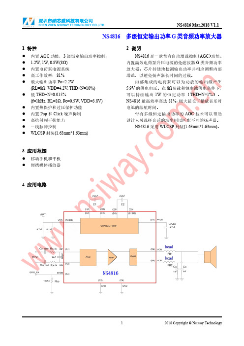
NS4816多级恒定输出功率G类音频功率放大器1特性●内置AGC功能,3级恒定输出功率控制:● 1.2W,1W,0.8W(8Ω)●内置电荷泵电源系统●高工作效率:81%●最大输出功率Po=2.2W(RL=8Ω,VDD=4.2V,THD+N=10%)●低THD+N=0.015%(f=1kHz,RL=8Ω,Po=0.5W,VDD=3.8V)●内置热保护和过压保护功能●内置Pop和Click噪声抑制●高抗射频干扰能力●一线脉冲控制●WLCSP封装(1.63mm*1.63mm)3应用范围●移动手机和平板●便携媒体播放器2说明NS4816是一款带有自动增益控制(AGC)功能、内置高效电荷泵升压电源的免滤波器G类音频功率放大器。
芯片持续地检测输出功率并相应调整内部增益,以避免扬声器长时间的过载。
内部集成的电荷泵可以为功放的输出级产生5.9V的供电电压。
在8Ω负载和锂电池供电条件下,可以持续输出1W的恒定功率(THD+N=1%)。
NS4816最高效率高达81%,极大延长了播放音乐时电池的续航时间。
带有多级恒定输出功率的AGC技术可以帮助设计人员选择合适的功率用以匹配不同的扬声器。
NS4816采用WLCSP封装(1.63mm*1.63mm)。
4应用电路5管脚配置NS4816WLCSP的俯视图如下图所示:NS4816管脚说明:管脚编号管脚名称管脚说明A1INP音频信号输入正端A2INN音频信号输入负端A3,B3VDD电源A4SHDN一线脉冲控制端B1,B2C2N电荷泵C2电容负端B4VOP音频放大器输出正端C1C1N电荷泵C1负端C2,C4GND地D1C2P电荷泵C2正端D2C1P电荷泵C1正端D3PVDD音频功放级电源D4VON音频放大器输出负端6极限工作参数参数最小最大单位供电电压范围VDD-0.3 5.2V输入电压范围INP.INN.SHDN-0.3VDD+0.3V工作温度范围-4085℃工作结温范围-40150℃储存温度范围-65150℃最小负载阻抗4ΩHBM ESD8000VMM ESD200VθJA15-ball WLCSP 1.63x1.63mm70℃/W注:如果器件工作条件超过上述极限值,可能对器件造成永久性损坏。
SAA5296资料

• 80C51 microcontroller core • 16/32/64 kbyte mask programmed ROM • 256/768/1280 bytes of microcontroller RAM • Eight 6-bit Pulse Width Modulator (PWM) outputs for control of TV analog signals • One 14-bit PWM for Voltage Synthesis Tuner control • Four 8-bit Analog-to-Digital converters • 2 high current open-drain outputs for directly driving LED’s etc. • I2C-bus interface • External ROM and RAM capability on QFP80 package version. 1.3 Teletext acquisition
The SAA529x, SAA529xA and SAA549x family of microcontrollers are a derivative of the Philips’ industry-standard 80C51 microcontroller and are intended for use as the central control mechanism in a television receiver. They provide control functions for the television system and include an integrated teletext function. The teletext hardware has the capability of decoding and displaying both 525-line and 625-line World System Teletext. The same display hardware is used both for Teletext and On-Screen Display, which means that the display features give greater flexibility to differentiate the TV set. The family offers both 1 page and 10 page Teletext capability, in a range of ROM sizes. Increasing display capability is offered from the SAA5290 to the SAA5497.
NS6112 8-30V输入2.6A输出同步降压稳压器说明书

NS61128-30V 输入2.6A 输出同步降压稳压器1特性●宽输入电压范围:8V 至30V ●宽输出电压范围:1.8V 至28V ●效率可高达92%以上●开关频率:130kHz ●过热保护●SOP-8封装●最大输出电流:2.6A2应用范围●车载充电器/适配器●线性调节前置稳压器●分布式供电系统●电池充电器3说明NS6112是支持高电压输入的同步降压电源管理芯片,在8~30V 的宽输入电压范围内可实现最大2.6A 的连续电流输出。
通过调节FB 端口的分压电阻,可以输出1.8V 到28V 的稳定电压。
NS6112具有优秀的负载调整率和线电压调整率,在全范围内不超过±5%。
NS6112采用电流模式的环路控制原理,实现了快速的动态响应。
NS6112工作开关频率为130kHz ,具有良好的EMI 特性。
NS6112内置线电压补偿,可通过调节FB 端口的分压电阻阻值来实现。
NS6112不仅可实现单芯片降压电源管理方案,还可以与QC2.0/QC3.0识别芯片构成快速充电电源管理方案。
另外,芯片包含多重保护功能:过温保护,输出短路保护和输入欠压保护等。
NS6112采用SOP8的标准封装。
4典型应用电路百盛新纪元半导体百盛新纪元半导体电话:135****2799Q Q :2851339680SOP-8的管脚图如下图所示:注1:超过上述极限工作参数范围可能导致芯片永久性的损坏。
长时间暴露在上述任何极限条件下可能会影响芯片的可靠性和寿命。
注2:NS6112可以在0℃到70℃的限定范围内保证正常的工作状态。
超过-40℃至85℃温度范围的工作状态受设计和工艺控制影响。
体导半元纪新盛百8电气特性工作条件:T=25℃,V9典型特性曲线下列特性曲线中,除非指定条件,T A =25℃,C IN =100uF,C OUT =470uF,L=47uH 。
百盛新纪元半导体10应用说明NS6112采用固定频率的电流模式架构。
SAA7327中文资料
7.14 7.14.1 7.14.2 7.14.3 7.14.4 7.14.5 7.14.6 7.14.7 7.14.8 7.14.9 7.14.10 7.14.11 7.15 7.15.1 7.15.2 7.15.3 7.15.4
7.15.5
7.15.6 7.15.7 8 9 10
11
12
13 14 15 15.1
元器件交易网
INTEGRATED CIRCUITS
DATA SHEET
SAA7327 Digital servo processor and Compact Disc decoder with integrated DAC for video CD (CD7 II)
Product specification File under Integrated Circuits, IC01
Supply of this Compact Disc IC does not convey an implied license under any patent right to use this IC in any Compact Disc application.
3 ORDERING INFORMATION
APPLICATION INFORMATION
PACKAGE OUTLINE
SOLDERING
Introduction to soldering surface mount packages Reflow soldering Wave soldering Manual soldering Suitability of surface mount IC packages for wave and reflow soldering methods
VSC7186资料

CAP0
C2 C1 C3
VSC7186
CAP1
C1=C2=C3= >0.1uF MultiLayer Ceramic Surface Mount NPO (Prefered) or X7R 5V Working Voltage Rating
Serializer The VSC7186 accepts TTL input data as four parallel 10 bit characters on the Ti(0:9) buses which are latched into the input registers on the rising edge of RFC1. The 10-bit parallel transmission character will be serialized and transmitted on the SOi+/- PECL differential outputs at the baud rate with bit Ti0 (bit a) transmitted first. User data should be encoded using 8b/10b or an equivalent code. The mapping to 10b encoded bit nomenclature and transmission order is illustrated below, along with the recognized comma pattern.
VITESSE
SEMICONDUCTOR CORPORATION
Advance Product Information
VSC7186
Table 1: Transmission Order and Mapping of a 10b Character
常见集成电路的型号及功能资料
查看文章常用集成电路型号功能说明2007-07-20 20:33型号----------------------功能ACP2371NI ---多制式数字音频信号处理电路ACVP2205--- 梳状滤波、视频信号处理电路AN5071 -----波段转换控制电路AN5195K -----子图像信号处理电路AN5265 ----伴音功率放大电路AN5274 ----伴音功率放大电路AN5285K ----伴音前置放大电路AN5342K---- 图像水平轮廓校正、扫描速度调制电路AN5348K ----AI信号处理电路AN5521 ---场扫描输出电路AN5551----- 枕形失真校正电路AN5560 ---50/60Hz场频自动识别电路AN5612 ----色差、基色信号变换电路AN5836 ---双声道前置放大及控制电路AN5858K TV/A V----切换电路AN5862K(AN5862S) ---视频模拟开关AN5891K ----音频信号处理电路AT24C02 ---2线电可擦、可编程只读存储器AT24C04 ---2线电可擦、可编程只读存储器AT24C08 ---2线电可擦、可编程只读存储器ATQ203 ----扬声器切换继电器电路BA3880S ----高分辨率音频信号处理电路BA3884S ----高分辨率音频信号处理电路BA4558N ----双运算放大器BA7604N ----梳状切换开关电路BU9252S 8bitA/D----转换电路CA T24C16 ----2线电可擦、可编程只读存储器CCU-FDTV ---微处理器CCU-FDTV-06 ----微处理器CD54573A/CD54573CS ---波段转换控制电路CH0403-5H61 ----微处理器CH04801-5F43 ---微处理器CH05001(PCA84C841) ----微处理器CH05002--- 微处理器CH7001C ---数字NTSC/PAL编码电路CHT0406 ----微处理器CHT0803(TMP87CP38N*) ---8bit微处理器CHT0807(TMP87CP38N) --8bit微处理器CHT0808(TMP87CP38N) --8bit微处理器CHT0818 ---微处理器CKP1003C ---微处理器CKP1004S(TMP87CK38N) ---微处理器CKP1006S(TMP87CH38N) ----微处理器CKP1008S(TMP87CK38N/F) ---微处理器CKP1009S(TMP87CH38N) ---微处理器CKP1105S(Z90231) ---微处理器CKP1301S(TMP87CH38N) ---微处理器CKP1403S ----微处理器CM0006CF---- 数字会聚校正电路CNX62A ---光电耦合器CNX82A ----光电耦合器CPF8598 ----存储器CTV222S.PRC1.2 ----微处理器CTV225S-PRC1 ---微处理器CTV591S.GW3---- 微处理器CXA1545AS TV/A V----多路切换电路CXA1642P -----背景歌声消除电路CXA1686M -----时钟信号发生器CXA1779P ----基色信号处理电路CXP1103S-9919EP ----微处理器CXP750096 ----微处理器CXP85332-108A---- 微处理器DM8361 ----单片集成TV小信号处理电路DPU2553/DPU2554 ----偏转信号处理电路DTI2251----- 数字色信号过渡特性改善电路GAL16V8C ----同步信号变换电路GD74LS10 -----三组3输入与非门GD74LS393 -----双4位二进制计数器GD74LS74A ----双D触发器GM99200B ----微处理器HA11508----- 图像及伴音信号转换控制电路HCF4046B ----低功耗通用锁相环电路HCF4052B ----双4选1模拟开关HCF4053BE 三组2路模拟开关HCT157 VGA信号与TV/A V同步信号切换电路HCT4046AD ----低功耗通用锁相环电路HD14066 ----四组双向模拟开关HD14066B---- 四组双向模拟开关HD14066BP -----四组双向模拟开关HEF4052 -----双4选1模拟开关HEF4053 ----三组2路模拟开关HEF4094 8级移位-存储总线寄存器HIC1015 ---开关电源稳压控制及保护电路HIC1016 ----开关电源稳压控制及保护电路HIC1026 -----保护模块HM4864P-12 -----随机存取存储器HPD6325C D/A-----转换电路HS0038 ----遥控信号接收电路IX0823GE -----微处理器IX1763CEN1 ----单片集成TV小信号处理电路JLC1562BF ----总线控制输入/输出口扩展电路K6274K/D ----图像中频带通滤波器K9450M---- 伴音第一中频带通滤波器KA2107 ---音频控制电路KA2500 ----宽带视频放大电路KA3S0680R ----开关电源专用厚膜电路KA3S0880RFB ---开关电源专用厚膜电路KA7630--- 多路稳压输出电路KB2511B ---数字偏转电路KONKA266(P83C266) ---微处理器KS88C3216 ---微处理器KS88C8324---- 微处理器L7805 5V---固定正稳压器L7808 8V---固定正稳压器L7812 12V----固定正稳压器L78LR05/L78LR05D/L78LR50-MA/L78M05F/L78M05FA/L78MR05/L78MR05FA 5V稳压复位电路L78OSO5FA 5V---可控稳压电路L7912 9V---定负稳压器L7918 18V---固定负稳压器LA2785 杜比逻辑处理电路LA4225 5W----音频功率放大电路LA4261 ---立体声功率放大电路LA4270 6W×2---音频功率放大电路LA4280 10W×2----音频功率放大电路LA4282 10W×2---音频功率放大电路LA4445 ---双声道音频功率放大电路M32L1632512A 同步图形存储器M34300N-587SP 微处理器M34300N4-555SP 微处理器M37210M3-508SP 微处理器M37210M3-800SP 多制式数字音频信号处理电路M37210M3-902SP 微处理器M37210M4-705SP 微处理器M37211M2-609SP 微处理器M37220M3 微处理器M37221M6-065SP 微处理器M37222M6-084SP 微处理器M37225 微处理器M37270MF-168SP 微处理器M37271MP-209SP 微处理器M37274EFSP 微处理器M37280 微处理器M37551MA-0545SP 微处理器M50436-688SP 微处理器M51131L 话筒演唱及混响音量控制电路M5218AP 双运算放大器M52340SP 单片集成TV小信号处理电路M52470AP 三通道4输入模拟开关M54573L 波段转换控制电路M62354FP 六通道8bitD/A转换电路M62438FP SRSM65839SP 数字式卡拉OK信号处理电路M66312P PIP控制电路M6M80011P 存储器M6M80041P 存储器MALF24C01 存储器MALF24C02 存储器MB3110A 超低音频信号处理电路MB81461-12RS 动态随机存储器MC14066BCP 四组双向模拟开关MC141625A 梳状滤波器MC141628 前置亮、色信号分离梳状滤波器MC144110P D/A转换电路MC14577C 双视频放大电路MC33064D5 复位用欠压检测电路MC44608 开关稳压电源电压模式控制器MC68HC16R1(SC43402CFC) 微处理器MCM6206BBE 32K×8bit快速静态随机存取存储器MCU2600 时钟信号发生器MM1031XS 宽带视频放大电路MM1053XS 多路信号高速切换电路MM1113XS 多路信号高速切换电路MM1495XD A/V切换电路MN1515TWE/TWP 微处理器MN152810TTD5 微处理器MN152811TIX 微处理器MN15282 微处理器MN1871675T6S 微处理器MN1871675T7M 微处理器MN1872432TWI 微处理器MN187-681 微处理器MN3868 1H基带延迟线电路MSP3410 多制式丽音解码电路MSP3410B 多制式丽音解码电路MSP3410D 多制式丽音解码电路MSP3410D-52 多制式丽音解码电路MSP3410D-CS 多制式丽音解码电路MSP3410D-PP-B4 多制式丽音解码电路MSP3410D-P0-B4 多制式丽音解码电路MSP3415D-AI I*IC总线控制多制式音频处理电路MSP3463G 音频信号处理电路NE5532N 内部补偿低噪声双运算放大器NE/SE567 音调与频率解码、锁相环电路NE567N 音调与频率解码、锁相环电路NJM2234L 伴音声道控制开关NJM2700L WOW音频处理电路NJW1103 杜比定向逻辑和音色选择电路NJW1132AL 伴音BBE处理电路NM24C04EN 存储器NN5099K/NN5199K 单片集成多制式TV小信号处理电路NP83C266BRNA 微处理器NV320P 数字视频信号处理电路NVM3060 存储器OM8361 单片集成TV小信号处理电路OM8361-VS0469 单片集成TV小信号处理电路OM8839 I*IC总线控制单片集成TV小信号处理电路OM8839PS I*IC总线控制单片集成TV小信号处理电路OM8839PS-K9G216 I*IC总线控制单片集成TV小信号处理电路ONWA KWEC42.2ONWA KWEC44.1OTT531 5V稳压复位电路P83C266BDR 微处理器P87C766 微处理器P87C766BDR(CKP1401S) 微处理器P87C766DT 微处理器PC74HT241P 线性驱动数据缓冲电路PC713F6 光耦合器PCA841P-177 微处理器PCA84C122/PCA84C222/PCA84C422/PCA84C622/ PCA84C822 PCA84C440P/401 微处理器PCA84C641 微处理器PCA84C840P-054 微处理器PCA8516 字符形成电路PCA8521 遥控编码发射电路PCA8521BT 遥控编码发射电路PCF8581P 存储器PCF8582 存储器PCF8589C-2 存储器PCF8594C-2 存储器PCF8598 E2PROM存储器PCF8598C-2 E2PROM存储器PCF8598E E2PROM存储器PCX8598X-2 E2PROM存储器PIP2250 PIP信号处理电路PQ05RF 受控5V稳压器PQ09RD11(78HR09) 受控9V稳压器PQ12RF 受控12V稳压器PQ12RF2 受控12V稳压器S24C08A 存储器SAA3010T 遥控信号发射电路SAA4955TJ 场存储器SAA4955TS 数字式场存储器SAA4956TJ 具有降噪功能的场存储器SAA4961 PAL/NTSC兼容梳状滤波器SAA4977H 倍场频处理电路SAA4981 单片集成16:9压缩处理电路SAA4991WP 运动估算和补偿、降低行间闪烁、变焦和降噪电路。
SAA7146о

咖
通过对 支持 P I C 总线的 B O I S中断 ,可实现 S A74 配置 寄存器 的初始 化 ,中断 向量为 1 H, A 16 A 它可 以提供 的功能有 P I C 单元搜 索、类码搜 索 、配置字/ 字节读 出和写入 等 . 1 )调 用 B O I S中断 ,来 获得总线和 单元号 ,写入配置字 . 2 )配置 基址寄存 器 ,以提供基 地址 .
问题 及 解 决 方法 .
关
键
词 :S A7 4 ;P I 线 ;视 频 ;接 口;虚 拟 设 备驱 动 程序 A 16 C 总 文 献标 识 码 :A
中图分 类 号 :T 3 P7
O 引 言
近年来 ,随 着多媒体技 术的发展 ,图形 图像 的处理技 术成为迫切 的需求 ,它广泛应 用于医疗 , 交通 ,公安 ,地质分 析等重要 方面 .P ip 公司生产 的 S A 16 hl s i A 74 多媒体 P I C 桥是 对于桌面视 频应 用系统 的高 集成度芯 片 ,它提 供了连接 P I C 总线 的端 口,从而 支持 P C的视频应 用 .
3 )配置 命令 寄存 器 ,以产 生和响应 P I C 周期 .
2 S A 1 6在视频采 集系统 中的应 用 A 74
21 7 4 . 1 6的视 频处 理特 性
1 )对 于任意的 P I C 设备 ,可实现实 时的视频 在帧缓 冲 区的双 向传输 . 2 )虚拟 内存支持 . 3 )最大分 辨率 4 9 × 9 . 5 4 5 0 0 4 )对于可视 电话和 电话 会议的镜象 处理 .
S TOP
P ERR拌
A c 3 ~0 DP I【l 】
图 l S 74 AA 1 6引 脚 框 图
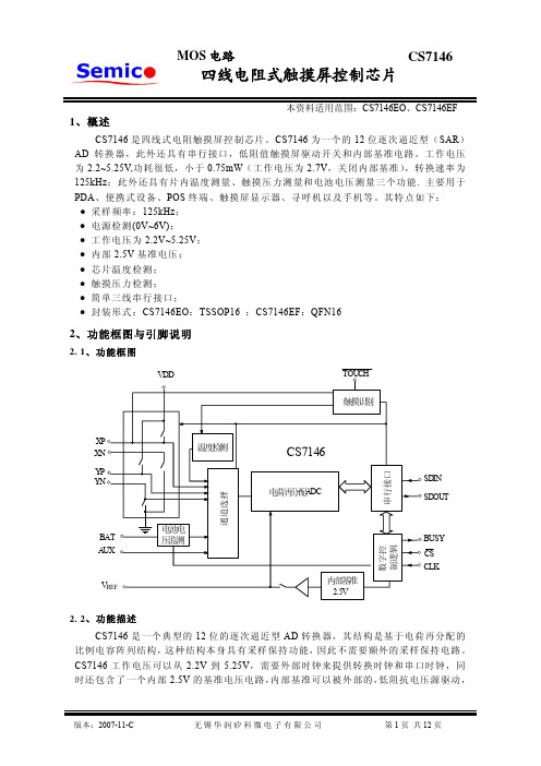
CS7146四线电阻式触摸屏控制芯片
版本:2007-11-C
无锡华润矽科微电子有限公司
第 5 页 共 12 页
MOS 电 路
CS7146
换 前 稳 定 到 最 终 的 电 压 值 。如 果 内 部 基 准 电 路 被 关 闭 ,要 保 证 有 足够的启动时间来启动内部基准电路。AD 转换器不需要启动时 间,可以瞬间启动。此外,随着 BUSY 置为高,内部基准电路的 工作模式将被锁存,需要对 CS7146 写额外的控制位来关闭内部 基准电路。
参考电压模式选择位,同 A2-A0 一起,设定 CS7146 的测量模式,
驱动开关和基准输入(见于表 4 和表 5)
省电模式选择,见于表 3
(1)起始位:控制字的第一位,必须为高,表明控制字的开始。CS7146 如果没有 检测到起始位,将忽略 DIN 上的信号;
(2)通道选择:接下来的三位,A2,A1 和 A0 用来设定 CS7146 的测量模式,驱 动开关和基准输入;
VDD
TOUCH
触摸识别
串行接口
XP XN
温度检测
CS7146
YP
YN
电荷再分配ADC
SDIN SDOUT
通道选择
BAT AUX
VREF
电池电 压监测
内部基准
2.5V
数字控 制逻辑
BUSY CS CLK
2. 2、功能描述
CS7146 是一个典型的 12 位的逐次逼近型 AD 转换器,其结构是基于电荷再分配的 比 例 电 容 阵 列 结 构 ,这 种 结 构 本 身 具 有 采 样 保 持 功 能 ,因 此 不 需 要 额 外 的 采 样 保 持 电 路 。 CS7146 工作电压可以从 2.2V 到 5.25V,需要外部时钟来提供转换时钟和串口时钟,同 时还包含了一个内部 2.5V 的基准电压电路,内部基准可以被外部的,低阻抗电压源驱动,
泽耀科技 A32-S400A22S1a 产品手册说明书

A32-S400A22S1a 产品手册基于SX126X 带屏蔽盖的433/470/490MHz,156mW,LoRa 扩频,IPEX 接口的射频收发模块版本:Spec_ A32-S400A22S1a _V1.0 日期:2021-05 状态:受控状态LoRa扩频,IPEX接口的射频收发模块 一 、产品概述A32-S400A22S1a是一款433/470/490MHz(中国频段),约156mW,高速,高稳定性,工业级的,集无线收发于一体的射频收发模块。
模块采用了SEMTECH原装SX126X射频芯片,工作在410~525MHz的ISM频段,带有金属屏蔽罩,抗干扰性能强。
该模块发射功率足,频谱特性优异,谐波非常小,频道串扰小,体积小,部分器件达到了军品级标准。
二 、产品特征●SX126X射频芯片●高性能IPEX天线接口和邮票口,传输距离可达5.0km[ 1 ]●超低功耗处理,最低功耗≤1uA●工作频段410~525MHz频率可调,信道间隔可调GFSK、FSK、MSK、GMSK、LORA、OOK调制●256 byte buffer●通信接口4-Pin硬件SPI通信接口推荐速率4Mbps,最大速率可达10Mbps●宽范围空中速率[ 2 ]可调空中速率,0.018-62.5kbps(LORA模式)●功率可调,最大功率约22dBm[ 3 ]●四种工作模式[ 4 ]睡眠模式(sleep down)待机模式(standby)发送模式(send)接收模式(receive)●供电电压范围[ 5 ]2.0V~3.6VDC●发射电流在发射功率为22dbm下,测得的发射电流约为108mA●接收灵敏度低至-148dBm●超小体积,贴片封装19.65*16mm模块重量约1.5gLoRa扩频,IPEX接口的射频收发模块备注:[ 1 ]晴朗空旷,无障碍物干扰;最大功率、高度2m、空中速率2.4kbps[ 2 ]空速越高,传输距离越近;空速越低,传输距离越远。
流行的及常用的6款发烧IC音频功率放大器

流行的及常用的6款发烧IC音频功率放大器流行的及常用的6款发烧IC音频功率放大器6片IC简介本文将为大家介绍现在流行的6款IC音频功率放大器,分别是美国国半公司的LM1875、LM4766、LM3886(LM4780)以及ST意法公司的TDA7293和TDA7294,它们的标称输出功率在30~100W范围内,适用于家用高保真音频功率放大器。
采用这几款IC的功放具有元件少、调试简单的特点,功率、音质与一般的分立元件功放相比毫不逊色,因此一直受到广大DIY发烧友,特别是初学者的喜爱。
JeffRowland的基于LM3886、TDA7293的功放跻身世界优秀功放之林,更证明了功率IC本身性能之优异。
关键词:音频功率放大器功率IC TDA7294 TDA7293 应用LM1875 LM4766 LM3886一、6片IC简介本文将为大家介绍现在流行的6款IC音频大功率放大器,分别是美国国半公司的LM1875、LM4766、LM386(LM4780)以及ST意法公司的TDA7293、TDA7294,它们的标称功率在30~100W范围内,适合于家用高保真音频放大器。
采用这几款IC的功放具有元件少,高度简单的特点,功率、音质与一般分立元件功放相比毫不逊色,因此一直受到DIY发烧友,特别是初学者的喜爱。
JeffRowland的基于LM3886、TDA7293的功放跻身世界优秀功放之林,更证明了功率IC 本身性能之优异。
虽然JeffRowland证明了功率IC可以好声,而且这些IC家喻户晓,使用者众多,但“IC音质不如分立元件”的观念却依然根深蒂固的扎根于广大DIY发烧友的头脑里。
很多人对这些芯片的认识来自未能发挥芯片的制作,造成对这些芯片的误解。
本文将从产品数据手册入手,多角度,深入地挖掘产品数据手册中包含的丰富信息,揭开数据背后隐藏的秘密,以求给大家一个全面的认识。
1. LM1875LM1875是美国国家半导体公司20世纪90年代初推出的一款音频功放IC,如图1所示。
海用产品介绍资料
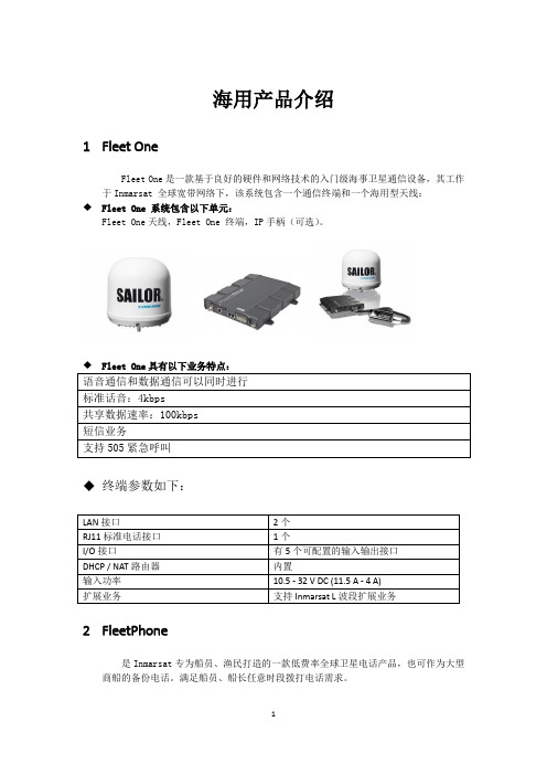
海用产品介绍1Fleet OneFleet One是一款基于良好的硬件和网络技术的入门级海事卫星通信设备,其工作于Inmarsat 全球宽带网络下,该系统包含一个通信终端和一个海用型天线:◆Fleet One 系统包含以下单元:Fleet One天线,Fleet One 终端,IP手柄(可选)。
◆终端参数如下:2FleetPhone是Inmarsat专为船员、渔民打造的一款低费率全球卫星电话产品,也可作为大型商船的备份电话。
满足船员、船长任意时段拨打电话需求。
Oceana 400 Oceana 800◆FleetPhone拥有如下业务特点:3FleetBroadband是Inmarsat迄今最先进的通信产品,通过一个天线,提供话音和数据同时在线服务,真正实现全球海上通信。
无论在何方,只要您拥有了FleetBroadband,您的船只可以连线任何人,任何地方。
FB首次实现了海上通信技术的宽带化和个性化,将船舶通信带入了IP数据业务的新时代。
基于3G标准,FB能提供宽带数据和语音同时在线功能。
一部终端即可满足多种信息通信需求,如打电话,收发短信、语音信箱、文件传输、传真、视频会议。
◆产品类型支持FB宽带业务的终端设备有三款,分别是FB150、FB250和FB500。
SAILOR 500 FleetBroadband和SAILOR 250 FleetBroadband 是最新一代应用Inmarsat 全球覆盖的卫星通信设备。
可靠、高速的IP通信和常规语音通信同时进行,海事宽带将为您提供一个全新级别的海事卫星通信。
FB150是为专业船舶例如工作船、渔船和休闲游艇提供的高质量有竞争力的通信终端。
FB150天线小巧,安装简便。
小型船舶首次可以获得可靠的、高质量的全球宽带网络和语音,是第一个为小型船舶量身打造的解决方案。
基于3G标准,FB提供全球无逢宽带连接。
拨打电话、收发邮件、网上冲浪、远程控制同时进行。
4FleetFleet 77, 55, 和33是Inmarsat系列海用通信产品,支持语音, 传真和高达128 kbps的数据。
多媒体PCI接口控制芯片SAA7146A及其应用解析
多媒体PCI接口控制芯片SAA7146A及其应用摘要:概述了多媒体处理芯片SAA7146A的主要特点,描述了其内部的主要结构和关键功能,介绍了其在视频音频处理领域的开发应用,并给出了在视频图像多媒体中相应实例。
关键词:多媒体 PCI总线信号处理图像采集现在,基于PC机的多媒体应用越来越广泛,各种视频、音频信号处理技术日新月异。
其中的关键技术之一就是计算机与各种外围多媒体器件的接口问题。
PC机可供选择的总线接口基本上有ISA、PCI、USB三种。
其中,ISA总线传输率很低,只有8MB/s,基本上已被淘汰;USB接口虽然对用户来说使用很方便,但它的数据传输率也不够高,USB1.1版的数据传输率只有12MB/s。
由于多媒体信号中的视频信号的实时处理对数据传输率要求很高,较高质量的彩色图像一般要求在30MB/s以上。
因此,具有33.3MHz主频的32位的数据传输达132MB/s,而64位的数据传输率高达264MB/s的PCI总线便在多媒体尤其是视频图像领域获得了广泛的应用。
在众多的PCI接口控制芯片中,Philips公司的SAA7146A不仅具有符合PCI协议的控制电路,还集成了功能强大的高性能视频和音频多媒体处理电路,能够与众多的视频编码器及解码器、压缩及解压缩等视频芯片和音频采样与处理芯片以及其它数字信号处理芯片进行无缝连接,完成它们与计算机机PCI总线的数据通信,为视频桌面系统、图像、声音等多媒体的应用带来极大方便。
1 SAA7146A的主要特点1.1 视频处理(1)支持帧缓冲器与系统虚拟内存之间全尺寸、全速度的视频传送,可为任何一款相应的PCI外围器件提供多种处理方式;(2)支持全带宽的PCI读写操作(最高可达132MB/s);(3)支持虚拟内存(每个DMA通道有4MB);(4)每帧最大可处理4095行,每行最大可处理4095个采样点;(5)具有针对视频电话和视频会议应用的图像镜像功能;(6)具有视频图像播转功能;(7)内置亮度、对比度、饱和度控制电路;(8)设置了寄存器编程序列器(RPS),能够对内部寄存器进行编程控制,可以同时处理两路异步数据流;(9)内置存储器管理单元电路(MMU),可支持Windows、Unix等系统的虚拟页模式存储器管理功能;(10)具有针对帧缓冲器的矩形裁剪功能,以减少PCI总线负载;图1 SAA7146A的原理框图1.2 音频处理(1)具有时间片序列处理功能,能够同在两个异步双向数字音频接口上实现最大256bit的音频帧的复杂控制;(2)多种同步模式支持I2S和其它音频及DSP数据模式;(3)具音频输入级监控功能,可通过软件实现峰值控制;(4)具有可编程的位时钟产生电路,从而可支持主动式和从动式两种应用。
7106中文资料
版本:1.0 2001-04-25 第 1 页 共 4 页概述CS7106AGP 是一种具有直接驱动LCD 功能的3位半A/D 转换电路。
电路具有很强的抗干扰能力。
CS7106AGP 的用途十分广泛,它可以组装成各种体积小、重量轻、便于携带的数字仪表,也可用于数控系统。
CS7106AGP 可与国外同类型号的电路互换使用。
功能特点! 采用单电源供电,电压范围7~15V ,可使用9V 叠层电池。
! 温度漂移低。
! 输出形式为异或门输出,能直接驱动LCD 。
! 采用CMOS 差动输入,输入阻抗高,对输入信号无衰减作用。
! 内部噪声低,显示稳定。
! 能通过内部模拟开关实现自动调零和自动极性显示。
! 内部有时钟电路,可接阻容元件构成多谐振荡器。
! 在芯片内部V +与COM 端之间,有一个稳定性很高的3.0V (典型值)基准电压源。
! 具有显示保持、电源低电压显示、A/D 正积分显示和A/D 反积分显示(注:DIP40封装无此四种功能)。
! 整机组装方便,所需外围元件少。
! 典型封装形式为DIP40(也可采用软封)。
管脚说明1. V +和V -分别接电源的正极和负极。
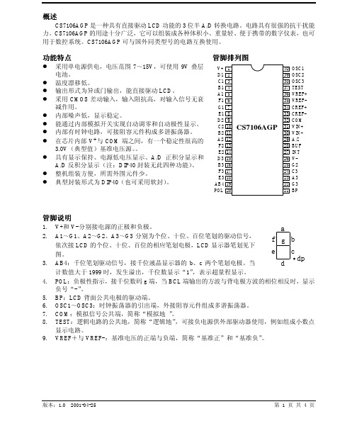
2. A1~G1、A2~G2、A3~G3分别为个位、十位、百位笔划的驱动信号,依次接LCD 的个位、十位、百位的相应笔划电极,LCD 显示器笔划见下图。
3. AB4:千位笔划驱动信号,接千位液晶显示器的b 、c 两个笔划电极。
当计数值大于1999时,发生溢出,千位数显示“1”,表示超量程显示。
4. POL :负极性指示,接千位数码g 端,当BCL 端输出的方波与背电极方波的相位相反时,显示负号“-”。
5. BP :LCD 背面公共电极的驱动端。
6. OSC1~OSC3:时钟振荡器的引出端,外接阻容元件组成多谐振荡器。
7. COM :模拟信号公共端,简称“模拟地 ”。
8. TEST :逻辑电路的公共地,简称“逻辑地”,可接负电源供外部驱动器使用,例如组成小数点显示电路。
- 1、下载文档前请自行甄别文档内容的完整性,平台不提供额外的编辑、内容补充、找答案等附加服务。
- 2、"仅部分预览"的文档,不可在线预览部分如存在完整性等问题,可反馈申请退款(可完整预览的文档不适用该条件!)。
- 3、如文档侵犯您的权益,请联系客服反馈,我们会尽快为您处理(人工客服工作时间:9:00-18:30)。
• Scaling of video pictures down to randomly sized windows (vertical down to 1 : 1024; horizontal down to 1 : 256) • High Performance Scaler (HPS) offers two-dimensional, phase correct data processing for improved signal quality of scaled video data, especially for compression applications • Horizontal and vertical FIR filters with up to 65 taps • Horizontal upscaling (zoom) supports e.g. CCIR to square pixel conversion • Additional Binary Ratio Scaler (BRS) supports CIF and QCIF formats, especially for video phone and video conferencing. 1.4 Interfacing
1998 Apr 09
3
元器件交易网
Philips Semiconductors
Product specification
Multimedia bridge, high performance Scaler and PCI circuit (SPCI)
1.5 General 2 GENERAL DESCRIPTION
• Dual D1 (8-bit, CCIR 656) video I/O interface • DMSD2 compatible (16-bit YUV) video input interface • Supports various packed (pixel dithering) and planar video output formats • Data Expansion Bus Interface (DEBI) for interfacing with e.g. MPEG or JPEG decoders with Intel (ISA like) and Motorola (68000 like) protocol style, capability for immediate and block mode (DMA) transfers with up to 23 Mbytes/s peak data rate • 5 digital audio I/O ports • 4 independent user configurable General Purpose I/O Ports (GPI/O) for interrupt and status processing • PCI interface (release 2.1) • I2C-bus interface (bus masterATED CIRCUITS
DATA SHEET
SAA7146A Multimedia bridge, high performance Scaler and PCI circuit (SPCI)
Product specification File under Integrated Circuits, IC22 1998 Apr 09
SAA7146A
Initialization of boundary scan circuit Device identification codes ELECTRICAL OPERATING CONDITIONS CHARACTERISTICS APPLICATION EXAMPLE PACKAGE OUTLINES SOLDERING Introduction Reflow soldering Wave soldering Repairing soldered joints DEFINITIONS LIFE SUPPORT APPLICATIONS PURCHASE OF PHILIPS I2C COMPONENTS
SAA7146A
• Full size, full speed video delivery to and from the frame buffer or virtual system memory enables various processing possibilities for any external PCI device • Full bandwidth PCI-bus master write and read (up to 132 Mbytes/s) • Virtual memory support (4 Mbytes per DMA channel) • Processing of maximum 4095 active samples per line and maximum 4095 lines per frame • Vanity picture (mirror) for video phone and video conferencing applications • Video flip (upside down picture) • Colour space conversion with gamma correction for different kinds of displays • Chroma Key generation and utilization • Pixel dithering for low resolution video output formats • Brightness, contrast and saturation control • Video and Vertical Blanking Interval (VBI) synchronized programming of internal registers with Register Programming Sequencer (RPS), ability to control two asynchronous data streams simultaneously • Memory Management Unit (MMU) supports virtual demand paging memory management (Windows, Unix, etc.) • Rectangular clipping of frame buffer areas minimizes PCI-bus load • Random shape mask clipping protects selectable areas of frame buffer • 3 × 128 Dword video FIFO with overflow detection and ‘graceful’ recovery. 1.2 Audio processing 1.3 Scaling
SAA7146A
• Subsystem (board) vendor ID support for board identification via software driver • Internal arbitration control • Diagnostic support and event analysis • Programmable Vertical Blanking Interval (VBI) data region for e.g. to support INTERCAST, teletext, closed caption and similar applications • 3.3 V supply enables reduced power consumption, 5 V tolerant I/Os for 5 V PCI signalling environment. 3 QUICK REFERENCE DATA SYMBOL VDDD IDDD(tot) Vi; Vo fLLC fPCI fI2S Tamb 4 digital supply voltage total digital supply current data input/output levels LLC input clock frequency PCI input clock frequency I2S input clock frequency operating ambient temperature PARAMETER
1998 Apr 09
2
元器件交易网
Philips Semiconductors
Product specification
Multimedia bridge, high performance Scaler and PCI circuit (SPCI)
1 1.1 FEATURES Video processing
• Time Slot List (TSL) processing for flexible control of audio frames up to 256 bits on 2 asynchronous bidirectional digital audio interfaces simultaneously (4 DMA channels) • Video synchronous audio capture, e.g. for sound cards • Various synchronization modes to support I2S and other different audio and DSP data formats • Audio input level monitoring enables peak control via software • Programmable bit clock generation for master and slave applications.
