锦睿智诚JRPT2024系列管道温度传感器使用说明书(V1.02)
温度传感器的使用方法
温度传感器的使用方法
首先,选择合适的温度传感器非常重要。
根据需要测量的温度范围、精度要求、环境条件等因素,选择合适类型的温度传感器。
常见的温度传感器包括热电偶、热敏电阻、红外线温度传感器等,每种类型的传感器都有其适用的场景和特点。
在选择温度传感器时,需要充分考虑实际使用环境和测量要求,以确保传感器的准确性和稳定性。
其次,安装温度传感器时需要注意一些细节。
首先,要确保传感器与被测物体
或环境接触良好,避免外界因素对测量结果的影响。
其次,要注意传感器的安装位置,避免受到外部干扰或物理损坏。
另外,对于一些特殊环境,可能需要考虑传感器的防水、防腐蚀等特性,选择相应的防护措施或型号。
接下来,接入温度传感器并进行接线。
根据传感器的类型和输出信号,选择合
适的接线方法和设备。
一般来说,温度传感器的输出信号可以是模拟信号,也可以是数字信号。
针对不同类型的信号,可以选择相应的数据采集设备或转换器,将传感器的输出信号转化为可读取或处理的形式。
最后,进行温度传感器的校准和测试。
在使用温度传感器之前,需要进行校准
和测试,以验证传感器的准确性和稳定性。
校准的方法可以根据传感器的型号和要求进行,一般包括零点校准和满量程校准。
校准完成后,可以进行实际的温度测量和应用。
总之,温度传感器作为一种重要的传感器设备,在各种场景中都有着广泛的应用。
正确的选择、安装、接入和校准方法,能够确保温度传感器的准确性和稳定性,为后续的温度测量和控制提供可靠的数据支持。
希望本文介绍的温度传感器使用方法能够对大家有所帮助,谢谢阅读!。
Yokogawa 温度传感器连接头转发器说明书
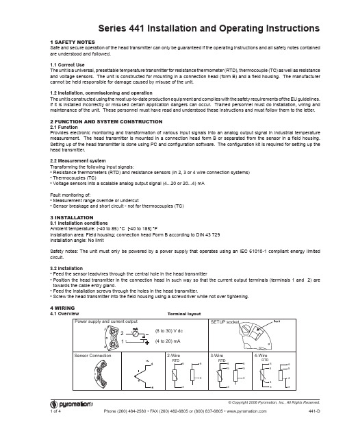
Series 441 Installation and Operating Instructions 1 SAFETY NOTESSafe and secure operation of the head transmitter can only be guaranteed if the operating instructions and all safety notes contained are understood and followed.1.1 Correct UseThe unit is a universal, presettable temperature transmitter for resistance thermometer (RTD), thermocouple (TC) as well as resistance and voltage sensors. The unit is constructed for mounting in a connection head (form B) and a field housing. The manufacturer cannot be held responsible for damage caused by misuse of the unit.1.2 Installation, commissioning and operationThe unit is constructed using the most up-to-date production equipment and complies with the safety requirements of the EU guidelines. If it is installed incorrectly or misused certain application dangers can occur. Trained personnel must do installation, wiring and maintenance of the unit. These personnel must have read and understood these instructions and must follow them to the letter.2 FUNCTION AND SYSTEM CONSTRUCTION2.1 FunctionProvides electronic monitoring and transformation of various input signals into an analog output signal in industrial temperature measurement. The head transmitter is mounted in a connection head form B or separated from the sensor in a field housing. Setting up of the head transmitter is done using PC and configuration software. The configuration kit is required for setting up the head transmitter.2.2 Measurement systemTransforming the following input signals:• Resistance thermometers (RTD) and resistance sensors (in 2, 3 or 4 wire connection systems)• Thermocouples (TC)• Voltage sensors into a scalable analog output signal (4...20 or 20...4) mAFault monitoring of:• Measurement range override or undercut• Sensor breakage and short circuit - not for thermocouples (TC)3 INSTALLATION3.1 Installation conditionsAmbient temperature: (-40 to 85) °C [-40 to 185] °FInstallation area: Field housing; connection head Form B according to DIN 43 729Installation angle: No limitSafety notes: The unit must only be powered by a power supply that operates using an IEC 61010-1 compliant energy limited circuit.3.2 Installation• Feed the sensor leadwires through the central hole in the head transmitter• P osition the head transmitter in the connection head in such way so that the current output terminals (terminals 1 and 2) are towards the cable entry gland.• Feed the installation screws through the holes in the head transmitter.• Screw the head transmitter into the field housing using a screwdriver while not over tightening.4 WIRING4.1 OverviewTerminal layout4.2 Measurement unit connectionAttention: Switch off power supply before opening the housing cover. Do not install or connect the unit to power. If this is not followed parts of the electronic circuit will be damaged.• S ensors: Connect the sensor lead to the respective head transmitter terminals (Terminals 3 to 6) by following the wiring diagram (see figure 4.1).• O utput signal and power supply: Open the PG cable gland on the head transmitter or field housing. Feed the cable through the opening in the PG cable gland and then connect the cable cores to terminals 1 and 2 according to the wiring diagram (see figure 4.1).• P C configuration (SETUP socket): Open the flap on the SETUP socket (Figure 4.1, Pos. A) and connect the SETUP connection cable.Note: The screws on the terminals must be screwed tightly. Head transmitter configuration during measurement operation is possible. There is no need to disconnect leads.POTENTIAL LEVELINGPlease take note when installing the head transmitter remotely in a field housing. The screen on the (4 to 20) mA signal output must have the same potential as the screen at the sensor connections. When using earthed thermocouples, screening of the output (4 to 20) mA cable is recommended. In plants with strong electromagnetic fields, screening of all cables with a low ohm connection to the transmitter housing is recommended.5 OPERATION5.1 Short form instructions (SETUP)For detailed TransComm operating instructions, please read the online documentation contained in the software.5.2 CommunicationThe head transmitter must be set up using a PC and configuration kit. The following points must be taken into account if troublefree setting up is to be achieved:• Configuration software installation• Connect the head transmitter to the PC using the connection cable from the configuration kit.7 MAINTENANCEThe head transmitter is maintenance free.8 TROUBLESHOOTINGAlways start troubleshooting with the checklists below if faults occur after start up or during operation. This takes you directly (via various queries) to the cause of the problem and the appropriate remedial measures. Note: Due to its design, the device cannot be repaired. However, it is possible to send the device in for examination.General errorsConnecting the head transmitter to the PC using the configuration kit connection cable 1. C onnect the SETUP connector of the interface cable to the SETUP socket in the head transmitter (see figure 4.1, Pos. A). 2. C onnect the RS232C connector to a free serial interface socket on the PC. In order to achieve optimum connection tighten the RS232C connector screws to the PC.Note: Configuration of the head transmitter must be done with power applied.6 COMMISSIONING 6.1 Installation checkMonitor all connections making sure they are tight. In order to guarantee fault free operation the terminal screws must be tight onto the connection cables. The unit is now ready for operation.6.2 CommissioningOnce the power supply has been connected the head transmitter is operational.Set up using the PC configuration softwareThe head transmitter left the factory with a default parameter configuration. If no customer specific configuration was mentioned on the order the default parameter configuration is constructed as follows:Hint: If a change has been made to the measurement point then the head transmitter can be re-configured. In order to re-configure the parameters follow these instructions:• Install the configuration software and make connection to the PC (see Chapter 5, Operation).• F or detailed operating instructions for the PC configuration software, please read the online documentation contained in the software.Interactive setting up of the temperature transmitterCustomer specific linearization and sensor matching is done using the TransComm configuration software. The program calculates the linearization coefficients X0 to X4, that need to be entered into the PC configuration software.6.3 Function checkMeasuring the analog (4 to 20) mA output signal or following failure signals:SensorPt100 (RTD)Connection mode 3-wire Measurement range and units(0 to 100) °CUnderranging Linear drop from 4.0 to 3.8 mA OverrangingLinear increase from 20.0 to 20.5 mAFailure, e.g. sensor breakage; sensor short circuit≤ 3.6 mA (“low”) or ≥ 21 mA (“high”), can be selectedThe “high” alarm setting can be set between 21.6 mA and 23 mA, thus providing the flexibility needed to meet the requirements of various control systems.Application errors for RTD sensor connectionApplication errors for TC sensor connection。
温度传感器说明书

DimensionalDrawings 4
Electricalconnection|HeadBig
Headunitwith1transmitter n( odisplay)andM12plug
Headunitwith1transmitter n( odisplay)andcablegland
V01
B
52.7 / 2.09
V52
F
66.0 / 2.60
V04
N
84.0 / 3.31
D2 [mm/inch] 31.0 / 1.22 50.0 / 1.97 68.0 / 2.68
FOOD
Processconnectionswithextendedtemperaturerange
CH|1 CLEANadaptM21
6mm
t50¡1.8s t90¡5.2s D: 8, 10, 12 mm
D
4mm
t50¡1.2s t90¡3.5s D: 6, 8, 10 mm
D
3mm
t50¡0.8s t90¡s2. D: 6 mm
D
4
3
d
Front“- ush t50¡2.5s t90¡15s
14 [0.55]
7 Installation|Warnings
Disposal
· Electrical devices should not be disposed of with household trash. They must be recycled in accordance with national laws and regulations.
· Take the device directly to a specialized recycling company and do not use municipal collection points.
ELJ系列温度传感器操作手册说明书

0,00385), de 3 o 4 hilos; conector hembra de 4 pines M12
Temperatura ambiente: -40 a 85 °C (-40 a 185 °F)
PIN #4
PIN #3
Para hacer su pedido
PIN #1 PIN #2
PIN #3 OPCIÓN DE CABLEADO #2
Accesorios
PIN #1 PIN #4
PIN #3 OPCIÓN DE CABLEADO #1
N.º DE MODELO RANGO DE ENTRADA
SPRTX-SS1-M12-(*) -99 a 208°C
SPRTX-SS2-M12-(*) 2 a 569°C (*) Especifique opción de cableado (ver diagramas): “1” para la opción de cableado 1, “2” para la opción de cableado 2
Transmisor SPRTX-SS con
U Protección exclusiva contra roturas
U Acondicionador de señales encapsulado
procedimiento CIP (limpieza en sitio) mediante una conexión de estilo M12. El transmisor SPRTX-SS se acopla directamente a una sonda Pt100 mediante una conexión M12, como la de la Serie PRS-S-M12C de OMEGA®, y proporciona
恒温传感器数据手册说明书
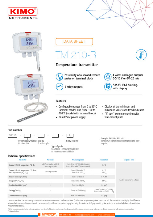
Temperature transmitter(1)All the accuracies indicated in this technical datasheet were stated in laboratory conditions, and can be guaranteed for measurements carried out in the same conditions, or carried out with calibration compensation.(2)Calculated values.Features•Configurable ranges from 0 to 50°C(ambient model) and from -100 to 400°C (model with terminal block)•24 Vdc/Vac power supply•Display of the minimum andmaximum values and trend indicator •“¼ turn” system mounting with wall-mount plate4 wires analogue outputs 0-5/10 V or 0/4-20 mA Possibility of a second remote probe on terminal block ABS V0 IP65 housing, with display2 relay outputsTM 210----Power supply/Output B: 24 Vac/Vdc Part numberDisplay O: with displayType of probeS: Ambient + Pt100 terminal block B: Two Pt100 terminal blocksExample: TM210 – BOS – RTemperature transmitter, ambient probe and relay outputs.Relay outputsRTM210 transmitter can measure up to two temperatures (temperature 1 and temperature 2). When two temperature probes are connected, the transmitter can display the difference between both measured temperatures. It can also calculate different parameters in psychrometry thanks to the KHP psycrometric probe available as option (only for models with two Pt100 terminal blocks).Warning: risk of electric shock2 x 4-20 mA or 2 x 0-20 mAor 2 x 0-5 V or 2 x 0-10 V (4 wires)DOUBLE ISOLATION ou ISOLATION RENFORCÉETechnical features of probesDifferent Pt100 temperature probes are available onthe range from -100 à +400 °C.Features of the housingAll dimensions are in millimeters.Ambient model Remote modelDimensionsPlease contact us in order to define the type of probethat corresponds to your need.ConnectiquesRelays 1 et 21234567LL+ 1. DIP switch (c)2. Pt100 n°1 terminal block3. Pt100 n°2 terminal block4. LCC-S software connection5. Relays6. Analogue outputs (a)7. Power supply terminal block (b)230 VacPeN-+0-5/10 V0/4-20 mAAf cheur régulateur ou automate type passifAf cheur régulateur ouautomate type passifSortie 4-20 mASortie 0-10 VConfiguration of the transmittersIt is possible on the class 210 to configure all the parameters of the transmitter: units, measuring ranges, outputs, channels, calculation func-tions, etc, via different methods:•Keypad for models with display: a code-locking system allows to secure the installation (See class 210 transmitters user manual).•Software (optional) on all models. Simple user-friendly configuration. See LCC-S user manual.Configurable analogue output:It is possible to configure your own intermediary rangesCaution: the minimum difference between the high range and the low range is 20.50-40 °C0 V 4 mA 0+180 °C10 V 20 mANew range-40 °C0 V 4 mA 0+180 °C10 V 20 mA50MountingTo mount the transmitter, mount the ABS plate on the wall (drilling: Ø6 mm, screws and pins are supplied).Insert the transmitter on the fixing plate (see A on the drawing beside). Rotate the housing in clockwise direction until you hear a “click” which confirms that the transmitter is correctly installed.MaintenancePlease avoid any aggressive solvent. Please protect the transmitter and its probes from any cleaning product containing formalin, that may be used for cleaning rooms or ducts.CalibrationOutputs diagnostic: With this function, you can check with a multimeter (or on a regulator / display, or a PLC / BMS) if the transmitter out-puts work properly. The transmitter generates a voltage of 0 V , 5 V and 10 V or a current of 4 mA, 12 mA and 20 mA Certificate: Class 210 transmitters are supplied with adjusting certificates. Calibration certificates are available as an option.Options and accessoriesPrecautions for usePlease always use the device in accordance with its intended use and within parameters described in the technical features in order not to compromise the protection ensured by the device.Only the accessories supplied with the device must be used.Les dimensions sont exprimées en millimètres.F T a n g – T M 210-R – 17/04/19 – R C S (24) P ér i g u e u x 349 282 095 N o n -c o n t r a c t u a l d o c u m e n t – W e r e s e r v e t h e r i g h t t o m o d i f y t h e c h a r a c t e r i s t i c s o f o u r p r o d u c t s w i t h o u t p r i o r n o t i c e .。
风管型氢气传感器产品说明书

风管式氢气传感器使用说明书V2.1济南智泽贸易有限公司目录第一章产品简介 (3)1.1.产品概述 (3)1.2.功能特点 (3)1.3.主要参数 (3)1.4.系统框架图 (3)第二章硬件连接 (9)2.1.设备安装前检查 (9)2.2.接口说明 (10)2.3.安装说明 (11)第三章配置软件安装及使用 (14)3.1.传感器接入电脑 (15)3.2.传感器监控软件的使用 (15)3.3.修改波特率和设备ID (16)第四章数字量传感器通信协议 (17)4.1.通讯基本参数 (17)4.2.数据帧格式定义 (17)4.3.寄存器地址 (18)4.4.通讯协议示例以及解释 (18)4.1.1读取设备地址0x01的H2值 (18)4.1.2读取设备地址0x01的温湿度值 (19)4.1.3读取设备地址0x01的温湿度、H2浓度值 (19)第五章模拟量传感器参数含义与换算 (20)5.1.模拟量4-20mA电流输出 (20)5.2.模拟量0-10V电压输出 (21)5.3.模拟量0-5V电压输出 (21)第六章常见问题与质量保证 (22)6.1.数字量设备无法连接到PLC或电脑 (22)6.2.模拟量无输出或输出错误可能的原因 (22)6.3.质保与售后 (23)第七章联系方式 (23)第八章免责声明 (23)第一章产品简介1.1.产品概述风管式氢气传感器专门为插入式管道气体测量而设计。
采用不锈钢导气管与不锈钢法兰结合的插入式结构,采用专业测试氢气浓度传感器探头作为核心检测器件;具有测量范围宽、精度高、线性度好、通用性好、使用方便、便于安装、传输距离远、价格适中等特点。
1.2.功能特点本产品采用高灵敏度的气体检测探头,信号稳定,精度高,快速响应,寿命长。
具有测量范围宽、线形度好、使用方便、便于安装、传输距离远等特点。
注意传感器为空气检测使用,客户应该在应用环境下测试以确保传感器符合要求。
1.3.主要参数H2测量范围0-1000ppm/0-4000ppm测量方式电化学传感器H2测量精度3%F.s响应时间一般小于15秒质保期主机质保2年,气体探头质保1年接口形式模拟量(电压/电流)/数字量(RS485)供电电源12V-24V DC风管型氢气传感器产品说明书 耗电<1W运行温度-30-50℃(-20-40℃持续)工作湿度环境0-100%RH(15-95%RH持续)风管长度200mm外形尺寸110×85×44mm31.1探头参数与选型编号探头类型量程分辨率寿命1KP进口霍尼韦尔1000ppm1ppm>2年40KP进口霍尼韦尔40000ppm10ppm>2年以上寿命均为温度23±3℃、湿度40±10%RH、浓度<5%最大量程的情况下的参考数1.4.系统框架图485型传感器本传感器可以连接单独使用,首先使用12V直流电源供电,设备可以直接连接带有485接口的PLC,可以通过485接口芯片连接单片机。
TI型号76DM0224电磁感应传感器说明书
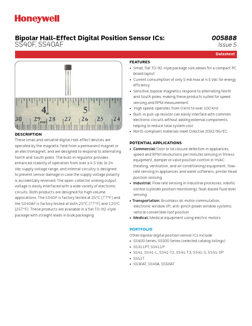
FEATURES• Small, flat TO-92-style package size allows for a compact PC board layout• Current consumption of only 5 mA max at 4.5 Vdc for energy efficiency• Sensitive, bipolar magnetics respond to alternating North and South poles, making these products suited for speed sensing and RPM measurement• High speed: operates from 0 kHz to over 100 kHz • Built-in pull-up resistor can easily interface with common electronic circuits without adding external components, helping to reduce total system cost• RoHS-compliant materials meet Directive 2002/95/EC POTENTIAL APPLICATIONS• Commercial : Door or lid closure detection in appliances, speed and RPM (revolutions per minute) sensing in fitness equipment, damper or valve position control in HVAC (heating, ventilation, and air conditioning) equipment, flow-rate sensing in appliances and water softeners, printer head position sensing• Industrial: Flow rate sensing in industrial processes, robotic control (cylinder position monitoring), float-based fluid level sensing• Transportation: Brushless dc motor commutation, electronic window lift, anti-pinch power window systems, vehicle convertible roof position• Medical: Medical equipment using electric motors PORTFOLIOOther bipolar digital position sensor ICs include:• SS400 Series, SS500 Series (selected catalog listings)• SS311PT, SS411P• SS41, SS41-L, SS41-T2, SS41-T3, SS41-S, SS41-SP • SS51T•SS30AT, SS40A, SS50ATDESCRIPTIONThese small and versatile digital Hall-effect devices are operated by the magnetic field from a permanent magnet or an electromagnet, and are designed to respond to alternating North and South poles. The built-in regulator provides enhanced stability of operation from over a 4.5 Vdc to 24 Vdc supply voltage range, and internal circuitry is designed to prevent sensor damage in case the supply voltage polarity is accidentally reversed. The open-collector sinking output voltage is easily interfaced with a wide variety of electronic circuits. Both products are designed for high volumeapplications. The SS40F is factory tested at 25°C [77°F] and the SS40AF is factory tested at both 25°C [77°F] and 125°C [257°F]. These products are available in a flat TO-92-style package with straight leads in bulk packaging.Bipolar Hall-Effect Digital Position Sensor ICs:SS40F, SS40AF005888Issue 523Advanced Sensing TechnologiesAdvanced Sensing TechnologiesBipolar Hall-Effect Digital Position Sensor ICs:SS40F, SS40AFBipolar Hall-Effect Digital Position Sensor ICs:SS40F, SS40AFNOTICEThese Hall-effect sensor ICs may have an initial output in either the ON or OFF state if powered up with an applied magnetic field in the differential zone (applied magnetic field >Brp and <Bop). Honeywell recommends allowing 10 us after supply voltage has reached 4.5 V for the output voltage to stabilize.NOTICEThe magnetic field strength (Gauss) required to cause the switch to change state (operate and release) will be as specified in the magnetic characteristics. To test the switchagainst the specified limits, the switch must be placed in a uniform magnetic field.Table 2. SS40AF Performance SpecificationsFigure 1. Current Sinking Ouptut Block DiagramFigure 2. Wiring DiagramsNOTICEAbsolute maximum ratings are the extreme limits the device will momentarily withstand without damage to the device. Electrical and mechanical characteristics are not guaranteed if the rated voltage and/or currents are exceeded, nor will the device necessarily operate at absolute maximum ratings.V s (+) Output (O)Ground (-)Honeywell Advanced Sensing Technologies 830 East Arapaho Road Richardson, TX /astFor more information Honeywell Advanced Sensing Technologies services its customers through a worldwide network of sales offices and distributors. For application assistance, current specifications, pricing or the nearest Authorized Distributor, visit /ast or call:Asia Pacific +65 6355-2828Europe +44 (0) 1698 481481USA/Canada+1-800-537-6945005888-5-EN | 5 | 05/21© 2021 Honeywell International Inc. All rights reserved .4Advanced Sensing TechnologiesBipolar Hall-Effect Digital Position Sensor ICs:SS40F, SS40AFWarranty/RemedyHoneywell warrants goods of its manufacture as being free of defective materials and faulty workmanship during the applicable warranty period. Honeywell’s standard product warranty applies unless agreed to otherwise by Honeywell inwriting; please refer to your order acknowledgment or consultyour local sales office for specific warranty details. If warranted goods are returned to Honeywell during the period of coverage, Honeywell will repair or replace, at its option, without charge those items that Honeywell, in its sole discretion, finds defective.The foregoing is buyer’s sole remedy and is in lieu of all other warranties, expressed or implied, including those of merchantability and fitness for a particular purpose. In no event shall Honeywell be liable for consequential, special, orindirect damages.While Honeywell may provide application assistance personally, through our literature and the Honeywell web site, it is buyer’s sole responsibility to determine the suitability of the product in the application. Specifications may change without notice. The information we supply is believed to be accurate and reliable as of this writing. However, Honeywell assumes no responsibility for its use.ADDITIONAL INFORMATIONThe following associated literature is available on the Honeywell web site at /ast:• Product Line Guide • Product Range Guide • Selection Guides•Application-specific InformationFigure 3. Mounting and Dimensional Drawings (For reference only: mm/[in].)SS40A, SS40AF: Straight Standard Leads, Bulk Pack3X 0,38。
温度传感器使用说明
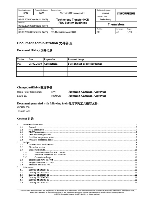
Executi ng division : Responsible division : Document type : Confidentiality status :HCN NVPTechnical Documentation InternalPrepared :Document state :08.02.2006 Czernietzki (NVP)Technology Transfer HCN PreliminaryChecked :09.02.2006 Czernietzki (NVP)FNC System BusinessThermistorsApproved :File:Revision :Language :Pages :09.02.2006 Czernietzki (NVP) TD-Thermistors-en-R001 001 en 1/19This document and its contents are the property of Hoppecke or its subsidiaries. This document contains confidential proprietary information. The reproduction,Document administration 文件管理Document History 文件记录VersionDateResponsibleReason of change001 08.02.2006 Czernietzki First release of the document.Change justifiable 变更审核Hans-Peter Czernietzki NVPPreparing , Checking , ApprovingLewis Liu HCN QS Preparing , Checking , ApprovingDocument generated with following tools 使用下列工具编写文件:WORD 200 <Grafic tool>Content 目录1 Overview Thermistors........................................................................................................................................................................2 1.1 General.....................................................................................................................................................................................2 1.2 NTC Thermistors.....................................................................................................................................................................4 1.3 PTC Thermistors......................................................................................................................................................................5 1.4 Lead wire configurations..........................................................................................................................................................6 1.5 Available temperature probe....................................................................................................................................................8 1.6 Available connection cables.....................................................................................................................................................8 2 Designs...............................................................................................................................................................................................9 2.1 Stainless steel block version.....................................................................................................................................................9 2.2 Electrolyte version...................................................................................................................................................................9 2.3 Connection cables..................................................................................................................................................................10 2.3.1 Two wire connection 414 220 0802.............................................................................................................................10 2.3.2 Four wire connection 414 220 0804............................................................................................................................10 2.3.3 Connection clamp........................................................................................................................................................10 2.4 Temperature curve PT100B...................................................................................................................................................11 2.5 Temperature curve NTC10K..................................................................................................................................................11 2.6 Technical data NTC10K.........................................................................................................................................................11 3 Attachments......................................................................................................................................................................................11 3.1 Drawing 2BZ60287-01..........................................................................................................................................................11 3.2 Drawing 3BZ60731-01..........................................................................................................................................................11 3.3 Drawing 2BZ60287-02..........................................................................................................................................................11 3.4 Drawing 3BZ60407-01..........................................................................................................................................................11 3.5 Drawing 3BZ60732-01..........................................................................................................................................................11 3.6 Drawing 3BZ60407-02. (11)1 Overview Thermistors电热调节器简介1.1 General总则Resistance elements come in many types conforming to different standards, capable of different temperature ranges, with various sizes and accuracies available. But they all function in the same manner: each has a pre-specified resistance value at a known temperature which changes in a predictable fashion. In this way, by measuring the resistance of the element, the temperature of the element can be determined from tables, calculations or instrumentation. These resistance elements are the heart of the RTD (Resistance Temperature Detector or short: Thermistor). Generally, a bare resistance element is too fragile and sensitive to be used in its raw form, so it must be protected by incorporating it into an housing.电阻元器件满足不同的标准,能够适用不同的温度范围,可满足多种尺寸和精度要求。
Gil 智能无线混合温度 压力传感器手册说明书

Si-RM3Smart wireless manifold P/T probeswith dual valves●Light and curved design for easy plug-in to facilities●Dual valve system for simultaneous measurement and charge/discharge of refrigerant●Built-in Schrader® cores for easy refrigerant charging●Range up to 60 bar (870 psi)●Reduce the use of cumbersome hoses●Overmoulding for easy handling and protection ●Two temperature clamps●Long range wireless connection 4.2 low energyDEVICE KEY FEATURESSI-MANIFOLD APP KEY FEATURESDIMENSIONS HOUSINGWeight560 g (4.8 oz)Control1 on/off buttonMaterialPressure gauges: ABS – PC andthermoplastic elastomerTemperature clamps: polyamid 6.6Batteries power supply3 alkaline AAA 1.5 V batteriesProtectionIP 54●Clear interface for easy reading in any condition●Gauge, table or graphic visualizations●Creation of measurements report with possibility to add pictures●Report exportation in PDF, CSV and XML formats●Data logging●Chronometer function●Free app for iOS and Android devices●Minimum required versions: Android 4.4, IOS 8.0, BLE 4.0●Vacuum measurement function●Configuration of vacuum target value●Temperature of water evaporationGeneral featuresVacuum features●Superheat and subcooling real time calculation●Configuration of superheat/subcooling target values●Heating and cooling functions●126 refrigerant gases with favorite listManifold featuresSmart wireless manifold probes for pressure andtemperature measurements in a refrigeration system.TECHNICAL DATA SHEET *See for conditions161 mm (6.3’’)128.4 mm (5.1’’)49.5mm(1.9’’)73.7mm(2.9’’)33.6mm(1.3’’)69.3 mm (2.7’’)112mm(4.4’’)28.4 mm(1.1’’)PressurePressure valves 2 valvesMeasuring range From -1 to 60 bar (-14 to 870 psi)Pressure sensing accuracy*±0.5% of full scaleAvailable units psi, MPa, kPa, bar, Foot of headResolution0.1 psi, 0.001 MPa, 1 kPa, 0.01 bar, 1 foot of headOverload65 bar (943 psi)Burst pressure150 bar (2175 psi)Operating temperature (handle)From -20 to 50°C (-4 to 122°F)Storage temperature (handle)From -20 to 60°C (-4 to 140°F)TemperatureNumber of probe 2 clamp probesTemperature sensors High accuracy NTC thermistorsTemperature sensor range**From -40 to 150°C (-40 to 302°F)Temperature accuracy*±1.3°C (±2.4°F)***Maximum operating temperatures Jaws: 150°C (302°F) - Cable: 105°C (221°F) - Handle : 90°C (194°F) Available units°C, °F, KResolution0.1°C, 0.1°F, 0.1 KPipes diameter From 6 to 42 mm (0.2'' to 1.7'')Cable 2 m (6 ft) length with strengthened Jack connector3 points, Ø3.2 mm, in PVC, max. temperature 105°C (221°F) Operating temperature From -20 to 50°C (-4 to 122°F)Storage temperature From -20 to 60°C (-4 to 140°F)DeviceEnvironmental conditions of use Hygrometry: in non-condensing condition (< 80% RH) Maximum altitude: 2000 m (6561')Non-corrosive or combustible gasesBattery life250 h (for one measurement every seconds @ 20°C / 68°F)Wireless connection Class 1 BLE 4.2Wireless connection range Up to 30 m (98 ft) - Depending on smartphone and tablet wireless connectionradio strength.Superheat and subcooling Automatically calculated by the Manifold appRefrigerant database126 refrigerant gases. Measurable products: CFC, HFC, HCFC, N, CO2, H20(see the complete list on the user manual)Connections To installation: female ¼’’ FFL with Schrader® depressorTo flexible: male ¼’’ MFL with Schrader® valveStandards2011/65/EU RoHS II; 2012/19/EU WEEE; 2014/30/EU EMC; 2014/53/EU RED TECHNICAL FEATURES* All accuracies specified in this document were conducted under laboratory conditions & can be guaranteed for measurement carried out in the same conditions, or carried out with calibration compensation. ** The temperature concerns the sensors operating range, do not use the handle or cables outside the indicated temperature.*** The temperature accuracy is given for the -20 to 80°C / -4 to 176°F range.KIT CONTENT●2 pressure probes. Ref: Si-RM1●2 temperature probes. Ref: Si-RM2●Adjustment certificate ●Simplified User Manual●6 AAA batteries ●Elastomer rings●Soft case. Ref: Si-RM4OPTIONSWARRANTYDevices have a 1-year manufacturer extended warranty. See conditions on Please always use the device in accordance with its intended use and within parameters described in the technical features in order not to compromise the protection ensured by the device.PRECAUTIONS FOR USEF T a n g _S i -R M 3_ 03/02/2021 _ N o n -c o n t r a c t u a l d o c u m e n t – W e r e s e r v e t h e r i g h t t o m o d i f y t h e c h a r a c t e r i s t i c s o f o u r p r o d u c t s w i t h o u t p r i o r n o t i c e .We recommend to use only accessories in compliance with the indicated manufacturer features.CLEANINGA cleaning is possible with isopropyl alcohol.OptionRef.IllustrationSet of three flexible hoses of 1m length (39'') with stop valvesACC25831Adaptation connector for R410 gasACC25830Velcro ® temperature probe for large diameter pipes.The Si-RM5 temperature probe works with the Si-RM1 smart wireless manifold probe to calculate superheat and subcooling. Measuring range: from -40 to 150°C. Cable: 2 m length with strengthened Jack connector.Si-RM5Extension cable for Si-RM2 and Si-RM5 probes. 5 m length.Si-RM6。
温度远传监测仪使用说明书

温度远传监测仪使用说明书一、概述:温度远传监测仪采用先进的微处理器进行智能控制,适用于温度物理量检测信号的显示控制,可巡回检测多路测量信号。
并能对各种非线性输入信号进行高精度的线性校正。
控制输出有远传变送输出;多路比较后最高测量点作为输出(远传变送输出)。
输出回路均采用光电隔离,具有良好的抗干扰能力。
具有高亮度LCD液晶显示。
外壳使用铝合金材质,整机采用壁挂式结构(长×宽×高=160×110×70mm),安装十分简便。
本产品可同时测量2至4个测量点,并将各个测温回路中的温度比较以后,把最高温度的一个点作为输出,在现场可通过按键逐个观看各个点的温度。
三、产品用途:1、回转密托轮油温2、密小齿轮油箱油温3、生料磨进出口轴承温度4、煤收尘器灰斗温度5、煤粉盒温度6、生料磨主电机绕组温度7、生料磨主电机轴承温度8、生料排风机电机定子温度9、高温风机绕组温度10、高温风机轴承温度五、仪表的结构六、电气连接仪表与外部PT100热电阻的接线需打开仪表盖以后进行,PT100热电阻相连接。
指示仪表、记录仪表,调节器等能够与电源串联在输出回路,输出电流正比于温度的变化,但独立于电源的变化,其应用原理如下图所示:NHR-XTRM温度远传监测仪自热电阻传感器的测量信号通过前置放大器放大,然后被比较输入电路(选择高温信号)或选点输入电路选中某一路信号,该信号通过电流(V/I)转换单元将放大器的输出电压变为4-20A恒定电流输出,原理方框图如下图所示:七、仪表使用说明开机后需预热10分钟,仪表的安装应该尽量靠近测量点,这样可以充分利用二线制的如下优点:1.高的抗干扰能力,因为信号是在高电平情况下传送,达到抑止噪声和干扰的作用。
2.简单的布线,即仪表从现场控制室采用双绞导线连接就可以了,降低了布线的成本。
输入采用热电阻时,为了避免测量误差,传感器的引线电阻必须保证一定的数值,这里对于每也可以取任何截面积的导线,但引线总电阻必须确保为0.35Ω。
温度传感器产品说明书

Specifications
Setpoint Range: 4 to 149°C (40 to 300°F)
Setpoint Tolerance: ±2.8°C (5°F)
Normally closed contacts, 4°C (40°F) Normally closed contacts, 10°C (50°F) Normally closed contacts, 15°C (60°F) Normally closed contacts, 21°C (70°F) Normally closed contacts, 27°C (80°F) Normally closed contacts, 32°C (90°F) Normally closed contacts, 38°C (100°F) Normally closed contacts, 43°C (110°F) Normally closed contacts, 49°C (120°F) Normally closed contacts, 54°C (130°F) Normally closed contacts, 60°C (140°F) Normally closed contacts, 65°C (150°F) Normally closed contacts, 71°C (160°F) Normally closed contacts, 77°C (170°F) Normally closed contacts, 82°C (180°F) Normally closed contacts, 88°C (190°F) Normally closed contacts, 93°C (200°F) Normally closed contacts, 99°C (210°F) Normally closed contacts, 104°C (220°F) Normally closed contacts, 110°C (230°F) Normally closed contacts, 115°C (240°F) Normally closed contacts, 121°C (250°F) Normally closed contacts, 127°C (260°F) Normally closed contacts, 132°C (270°F) Normally closed contacts, 138°C (280°F) Normally closed contacts, 143°C (290°F) Normally closed contacts, 149°C (300°F)
水管温度传感器+变送器+说明书-V3

水管温度传感器/变送器______说明书______概述水管管道式温度传感器/变送器,可以用于各种空调水系统及制冷剂等介质温度测量。
有多种探针长度结构可选择。
为方便现场安装及保护传感元件及产品不受被测液体浸蚀,对特殊的液体应与相应的套管配合使用。
产品采用高性能内置线性处理器,有多种输出信号可选,是专业应用于HVAC管道系统内温度测量设备。
水管温度传感器/变送器,采用分体式更加方便安装使用。
探针直径为Φ6.35mm,有多种长度可选。
同时配有独特的弹力卡簧设计,可保证温度测量的快速响应和准确性。
此系列产品可配带1/2-NPT螺纹的套管配合使用。
特点-高精度温度传感器-适用于各类智能建筑环境监控,暖通空调系统-先进的电路设计,测量精度高-性能稳定,线性度好-易安装,性价比高-多种输出方式可选-出厂标准校准应用-暖通空调-电子厂房-机房环境监控-动力环境监控-农业环境监控-气象环境监测-生物制药环境监控-机场,地铁站,酒店,博物馆,体育馆等技术参数温度测量精度:测量范围:参数稳定时间:校准:±0.2℃、±0.3℃、±0.5℃、±1℃0~50℃、0~80℃、-5~60℃具体请参照选型表2-5分钟标准校准输出参数信号输出:4~20mA RL<400ohm0~10VDC RL>10k ohm具体请参照选型表485参数信号类型:RS485类型:连接:地址:通讯协议:数据格式:波特率:RS485串口输出多点,半双工2线制,最大通讯距离1200米,端子直接连接1-254,通过开关/软件设置,广播地址为:0,默认地址为:1 MODBUS1起始位,8数据位,无奇偶,2终止位1200bit/s,2400bit/s,4800bit/s,9600bit/s,19200bit/s,28800bit/s,38400bit/s,通过软件设置,默认值为:9600bit/s能耗供电电源:电流型24VDC±10%电压型24VDC/AC±10%RS48510~28VDC接线方式接线端子:线缆规格:5.0mm间距,M3钢螺丝,0.2Nm扭矩,0.02欧姆接触电阻24~18AWG(0.2~1.0mm2),剥线长度6-7mm环境工作环境:温度-20...+70℃分体探头最高达200℃湿度0...99%RH,无冷凝储存环境:温度-30 (80)湿度0-95%RH,无冷凝防护等级外壳防护等级:电磁兼容:IP65参考IEC529–598/GB700–86/GB4208参考GB/T13926,EN61000-6-2,EN61000-6-3配件套管材质:螺纹规格:T50A套管长度:T50B套管长度:304/黄铜1/2-NPT,可定制100/150mm 50…350mm材料与颜色外壳:探头:探针长度:重量:ABS(黑色/浅蓝色) 304不锈钢100…400mm350g(整机重量)外形尺寸单位:mm注:可不带铜连接头探针长度,最终根据套管进行配套配件单位:mm材质:黄铜/304不锈钢注:套管L长度:110、160mm,配合探针的长度为100mm和150mm,带内牙螺纹与铜连接头配合使用。
温度传感器的使用方法

温度传感器的使用方法
温度传感器是一种测量温度变化的设备,使用方法如下:
1. 打开温度传感器的包装盒,取出传感器。
2. 将传感器插入测量对象中,通常情况下,传感器与测量对象接触的表面应该是平整的,并要避免传感器与任何物体相互接触。
3. 确认传感器与测量对象接触良好,然后将传感器插入温度计或温度计显示屏的插头。
4. 启动温度计,并设置合适的温度范围和单位。
然后读取屏幕上显示的温度数值。
5. 按需调整设置,如需要重新设置温度单位或调整范围等。
如果需要存储数据,可以将数据通过连接电脑的数据接口进行传输,保存到电脑上。
6. 使用完毕后,将传感器从测量对象中拔出,将其回收到包装盒中。
温度传感器可以广泛应用于实验室科研、医疗、食品安全等领域,需要注意在使用过程中保持设备的干燥、整洁,避免过度曝气、污染和损坏。
温度感应器使用说明(英文版)

Response time at 300°C 11m/s 800°C 70m/s
TS
TEMPERATURE (℃)
Electrical Interface
Element Resistance
Rs = RW + RE = RW + R0 (1 + αT + βT2)
Rs RW RE R0 T α
β
Temp' (℃ )
-40 -30
Total Sensor Resistance Resistance of Wire Resistance of Element Resistance of Element at 0 ℃ Temperature in ℃ Char. Line parameter Char. Line parameter
2.3
2.3 2.2
3.0
3.0 3.0
220
230 240
364.18 1.335
371.31 1.354 378.45 1.373
2.1
2.1 2.1
3.0
3.0 3.0
850
900
767.46 2.171
795.51 2.215
5.4
5.6
9.5
10.0
100
276.78 1.084
2.2
3.0
(peak) 950℃ 900℃
Sensor Housing: Inconel 600
Mounting Flange Stainless Steel 304 or 316 Connection Cable
Normal operating range
Pt200 Characteristic
管道温湿度传感器安全操作及保养规程
管道温湿度传感器安全操作及保养规程温湿度传感器是工业生产和实验室环境中常见的仪器之一,负责监测管道内部的温度和湿度等参数,以保障生产与实验安全。
如何做好这些传感器的安全操作与保养,是确保仪器长期稳定工作的关键。
本文主要介绍管道温湿度传感器的安全操作及保养规程,详述传感器的正确使用方法,以及相关的保养措施。
管道温湿度传感器的介绍管道温湿度传感器作为工业生产和实验室环境中常用的参数监测仪器,其主要作用就是检测管道内部的温度和湿度等参数。
它的结构简单,通常由一个温湿度传感器和一个接线盒组成,主要应用于冷库、水处理、食品加工、电器制造等领域。
现在市面上的管道温湿度传感器,包括两大类:有线和无线。
有线的传感器需要接线盒与电缆连接,而无线的则是通过无线传输技术实现数据的传输。
在传感器的安装与保养中,两种传感器的操作有所不同,需要特别注意。
管道温湿度传感器的安全操作规程管道温湿度传感器的正常工作,需要注意一些操作规范和技术细节,以确保进入工作状态,同时保障仪器的安全和稳定。
下面是在使用管道温湿度传感器时应注意的规程:1. 安装前的检查在安装前,必须先检查仪器本身是否存在异常,如外壳是否有磨损、温湿度传感器的灵敏度是否正常等。
同时,在安装之前需要确认管道系统的状态,并与相关部门沟通确认,以防止无谓的损失。
检查之后,在仪器与管道进行连接前,要确保与其它设备的连接正常,以保障传感器测量数值的准确性。
2. 安装时的操作传感器的位置必须放在可以掌握整个管道系统的位置,对于有线传感器,需要将传感器与接线盒连接,将接线盒安装于易于维修或安装的地方;对于无线传感器,需要通过相应的配套设备,将传感器接入系统。
在连接过程中,如果出现困难、或者不确定操作流程时,需要及时查阅相关文档,或者寻求工程师的帮助。
3. 正确的测量操作仪器安装好之后,需要按照标准操作流程,对仪器进行测量,比如是否需要校准传感器,确定测量频率等,以确保测量结果的正确性。
湿度与温度传感器产品说明书
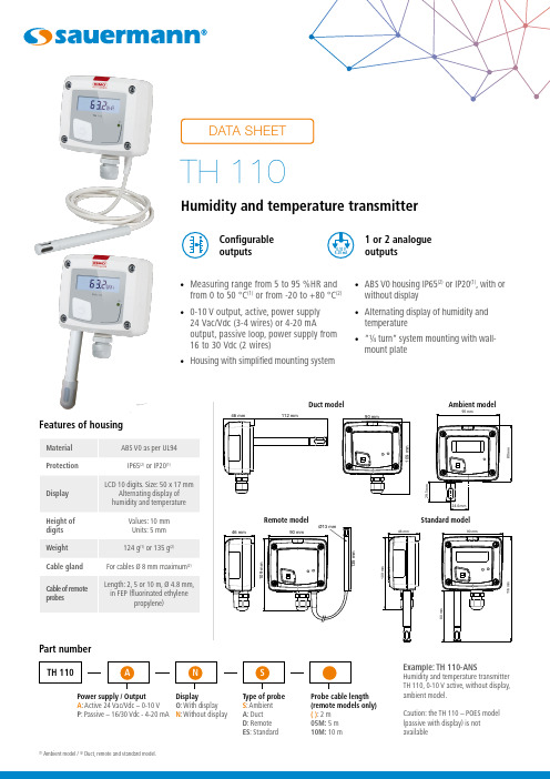
• Measuring range from 5 to 95 %HR and from 0 to 50 °C (1) or from -20 to +80 °C (2)• 0-10 V output, active, power supply24 Vac/Vdc (3-4 wires) or 4-20 mAoutput, passive loop, power supply from 16 to 30 Vdc (2 wires)• Housing with simplified mounting system• ABS V0 housing IP65(2) or IP20(1), with orwithout display • Alternating display of humidity and temperature • “¼ turn” system mounting with wall-mount plateFeatures of housingPart numberPower supply / Output A : Active 24 Vac/Vdc – 0-10 V P : Passive – 16/30 Vdc - 4-20 mA Display O : With display N : Without displayType of probe S : Ambient A : Duct D : Remote ES : StandardExample: TH 110-ANSHumidity and temperature transmitter TH 110, 0-10 V active, without display, ambient model.Caution: the TH 110 – POES model (passive with display) is not availableConfigurable outputs1 or2 analogue outputs(1)Ambient model / (2) Duct, remote and standard model.Ambient modelDuct modelProbe cable length (remote models only)( ): 2 m 05M: 5 m 10M: 10 mStandard modelTechnical specificationsConnectionsInside the front housing 1. Active switch (S1)2. Inactive switch3. LCC-S software connection4. Output terminal block5. Power supply terminal block6.Cable glandSimplified calibrationElectronic board and measuring element connected to the front side of the sensor, which allows toconfigure and calibrate your device without causing any damage.12Removable front face Fixed back housingGeneral features*Can be configured by switch.**All the accuracy indicated in this technical datasheet were stated in laboratory conditions, and can be guaranteed for measurements carried out in the same conditions, or carried out with calibration compensation.Measuring range Analogue output*654316354(standard model)Electrical connections as per NFC15-100 standardsThis connection must be made by a qualified and trained technician.IRH Vdc IT Vdc 1 2 hilos - +- +IRH Vdc IT Vdc IRH VdcIT Vdc IRH VdcIT Vdc symbol:F T _E N – T H 110 – 06/01/23 – N o n -c o n t r a c t u a ld o c u me n t – W e r e s e r v e t h e r i g h t t o m o d if y t h e c h a r a c t e r i s t i c s o f o u r p r o d u c t s w i t h o u t p r i o r n o t i c e .Only the accessories supplied with the device must be used.T o configure the transmitter , it must not be energized. Then, you can make the settings required, with the DIP switches (as shown on the drawing below).When the transmitter is configured, you can power it up.Please follow carefully the combinations beside with the DIP switch. If the combination is wrongly done, the following message will appear on the display of the transmitter “CONF ERROR”. In that case, you will have to unplug the transmitter , place the DIP switches correctly, and then power the transmitter up.1234Off OnActive switchUnit settingOutput setting On-off switch1234Active switch (S1)Please refer to the user manual of the LCC-S software to make the configuration.Set the DIP switches as shown beside. Connect the cable of the LCC-S to the connection of the transmitter .PC configurationSettings and use of the transmitterIt is possible to set the measuring ranges and the unit of the instrument either by switch and/or via software.Configurationis correctly installed. Ambient model does not have any mounting plate. 4 fixing holes are present inside the back Configuration via LCC-S software (option)It is possible to configure intermediate ranges, an offset...Example: for a 0-100 °C transmitter, minimum delta is 20 °C.The instrument can be configured from 0 to +20 °C or from -10 to +10 °C. In order to compensate a possible drift of the sensor, it is possible to add an offset to the displayed value by the TH 110 transmitter: it shows 48% RH, a standard instrument shows 45% RH. It is then possible, via the software, to integrate an offset of -3 to the displayed value by the TH 110 instrument.The configuration of the parameters can be done either with the DIP switch or via software (you can not combine both solutions).WarrantyInstruments have 1-year guarantee for any manufacturing defect.Maintenance:• Avoid any aggressive solvent.• Protect the transmitter and its probes from any cleaning product containing formalin, that may be used for cleaning rooms or ducts.Precautions for use: always use the device in accordancewith its intended use and within parameters described in the technical features in order not to compromise the protection ensured by the device.。
- 1、下载文档前请自行甄别文档内容的完整性,平台不提供额外的编辑、内容补充、找答案等附加服务。
- 2、"仅部分预览"的文档,不可在线预览部分如存在完整性等问题,可反馈申请退款(可完整预览的文档不适用该条件!)。
- 3、如文档侵犯您的权益,请联系客服反馈,我们会尽快为您处理(人工客服工作时间:9:00-18:30)。
JRPT2024系列管道温度变送器
使用说明书
(V1.02)
一、概述
JRPT2024系列管道温度变送器采用PT100作为信号测量元
件,把温度准确的测量出来。
经过数字信号调理电路转换成标准的4-20mA 电流输出。
温度变送器抗干扰、稳定性高、具有很高的测量精度,是工业自动化领域理想的温度测量仪表。
二、工作原理
温度变送器是采用PT100传感器采集温度,会产生一个对应温度变化的阻值变化,经电桥转变为差动电压信号,此信号经专
用放大器,24位高精度AD 采样校准后,输出与输入温度成线性对应关系且稳定的4-20mA 电流信号。
主要特点:
1、24位高精度AD 采集。
2、工业级单片机、稳定可靠。
3、宽电压供电、防反接及静电保护。
4、结构小巧,安装简单方便。
5、全不锈钢结构,抗振动冲击、抗射频干扰。
三、参数指标
项目参数
单位
低
中高
测量介质液体(对不锈钢壳体无腐蚀)、固体、气体
输出信号
4~20
mA
供电电源122432V
温度量程0~50、0~100(可定制)℃
精度等级-0.50.5%FS
长期稳定性-0.050.05%FS/年
环境温度-4085℃
存储温度-4085℃
防护等级IP65
外壳不锈钢
赫斯曼接头ABS工程塑料
四、产品外形尺寸
引线式航插式赫斯曼接头式
五、电气引脚定义及接线图
1、引线式变送器引脚定义
2、航插式变送器引脚定义
1、VCC:电源正
3、S:信号输出
3、赫斯曼式变送器引脚定义
1、VCC:电源正
2、S:信号输出
4、客户端电气连接方式
五、规格型号
六、安装方法及要求
1、必须由阅读并理解本说明书的专业技术人员进行安装。
2、本产品适用于各种一般腐蚀性液体及气体压力测量,禁止测量与变送器接触材质不兼容的介质。
3、本产品非防爆,在防爆区使用会引起严重的人身伤害和重大的物质损失。
4、要轻拿轻放不能随意抛扔,安装时请不要使用蛮力。
5、如果被安装在恶劣现场会遇到雷击或过压等危险的损坏时,我们建议用户在配电箱或电源与变送器
之间进行防雷击和过压保护。
6、安装孔位尺寸:确保安装孔位尺寸及螺纹规格;如不合适,在安装过程中将很容易导致传感器螺纹
部分受到磨损,影响设备的密封性能,甚至产生安全隐患。
7、本产品属于弱电设备,布线时必须与强电线缆分开布设,应遵守国家相关布线标准
(GB/T50312-2016)进行布线。
七、注意事项
1、收到产品后请确认产品是否完好后,并核对该型号是否与您选购的型号一致。
2、禁止本品用于与不锈钢不兼容的测量介质。
3、确保供电电压符合产品供电需求,并且接线正确、牢固。
4、不能在设备上进行任何修改或变更。
5、变送器有密封接头处不得松动,必须保持可靠密封。
6、变送器必须按规格使用,不同类型不能互换。
7、使用时请严格按注意事项执行,否则后果自负。
