T255温度传感器使用说明
红外测温仪的操作指南及各模块说明
《红外测温仪的操作指南及各模块说明》红外测温仪操作指南:将单片机连接电源后,只需将红外测温仪的红外探头瞄准被测物体,按下矩阵键盘上的S13按钮(设定为“开始测温”),测温仪开始工作,LCD显示屏上显示两个温度数值,上为被测点温度,下为环境温度(由探头外环探测得出)。
由于探头精度灵敏,温度数值在稳定建立时间过后仍有小幅度跳变。
按下矩阵键盘上的S14按钮(设定为“STOP”),LCD显示按下时刻的温度值,方便读数。
按下S13“开始测温”,测温仪开始新一轮测温。
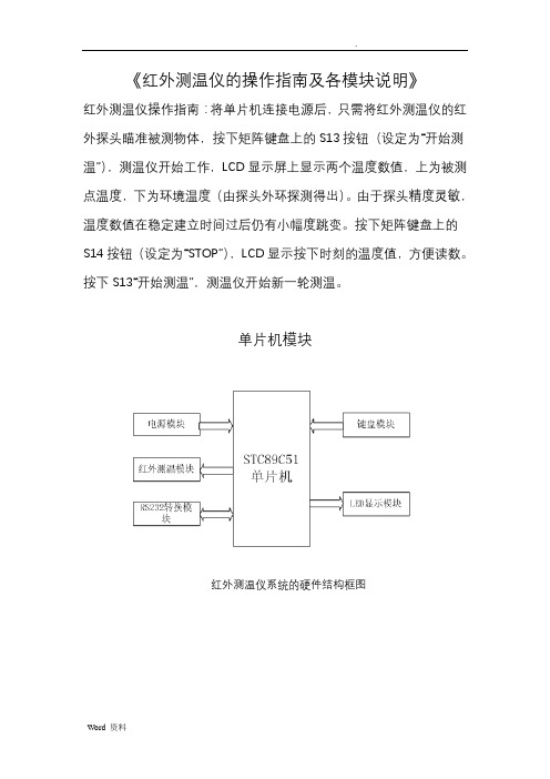
单片机模块红外测温仪系统的硬件结构框图红外测温仪系统的软件方案设计框图主程序模块:主要完成系统初始化,温度的检测,串行口通信,键盘和显示等功能。
其中系统初始化包括: 时间中断的初始化、外部中断源的初始化、串口通信中断的初始化、LED 显示的初始化。
红外测温模块:包括获取温度数据,计算温度值。
键盘扫描模块:获取按键信息,处理按键请求等。
显示模块:获取并处理相应的温度数据,通过LED数显管显示温度数据。
单片机处理模块单片机模块的工作原理是:加载相应程序的STC89C51单片机把红外测温模块传来的数据加以处理,送LED显示屏显示。
下图1是单片机处理模块的电路原理图图1 单片机处理模块电路图其复位电路如图2-1左边上部分,本单片机处理模块是通过开关手动复位的,只要在RST引脚出现大于10ms的高电平,单片机就进入复位状态,这样做的目的是便于根据实际情况而选择是否复位温度测量数据。
而此仪器的震荡电路选用的是晶体震荡电路,其具体电路如图2-1左边下部分。
采用晶体震荡电路的原因是因为它的频率稳定性好,而这正是本红外测温仪非常重要的技术要求。
单片机作为红外测温仪的核心处理部件,它关系到整个仪器的性能指标。
因此它的选择是非常重要的。
本测温仪选择的STC89C51RC单片机,下面是STC89C51RC单片机相关资料信息:STC89C51RC单片机是宏晶科技推出的新一代超强抗干扰/高速/低功耗的新一代8051单片机,指令代码完全兼容传统8051单片机,12时钟/机器周期和6时钟/机器周期可任意选择,最新的D版本部集成MAX810专用复位电路。
基于PLC温度控制系统设计

编号: 毕业论文(设计)题目基于PLC温度控制系统的设计指导教师学生姓名学号专业自动化教学单位机电工程学院毕业论文(设计)开题报告书德州学院毕业论文(设计)中期检查表院(系):机电工程学院专业:自动化 2014 年 4月 7日目录1引言 (2)1.1课题背景以及研究的目的、意义 (2)1.2温控系统的现状 (2)1.3项目研究内容 (3)2系统硬件设计 (4)2.1 PLC选择 (4)2.2 硬件电路设计 (7)3 系统软件设计 (13)3.1 编程与通信软件的使用 (14)3.2 程序设计 (14)3.3 系统程序流程图 (15)3.4 控制系统控制程序的开发 (16)4系统的仿真和运行测试 (25)4.1 组态王的运行 (25)4.2 实时曲线的观察 (26)4.3 分析历史趋势曲线 (27)4.4 编辑数据的报表 (27)4.5系统稳定性测试及最终评估 (27)参考文献 (29)谢辞 (30)附录一三菱FX系列PLC指令一览表 (30)附录二系统程序(梯形图) (32)基于PLC温度控制系统的设计(德州学院机电工程学院,山东德州253023)摘要:本文主要介绍了基于日本三菱公司FX2N系列的可编程控制器从而进行硬件设计和软件设计,进而完成了一个完整的关于炉温控制系统的设计方案。
该设计编程时调用了PID控制模块,使得程序更为简洁,运行速度更为理想。
在软件上,则是通过利用比较新型的三菱专用软件三菱(PLC)GX Developer 8.86Q,实现控制系统的实时监控、数据的实时采样与处理。
实验证明,此系统具有快、准、稳等优点,在工业温度控制领域能够广泛应用。
关键词:温度控制;可编程控制器;三菱FX2N;PID控制模块1引言1.1课题背景以及研究的目的、意义进入21世纪后,我国社会的各项发展突飞猛进,世界的技术更是日新月异,竞争也愈演愈烈,传统的人工的操作已不能满足于目前的制造业前景,也无法保证高质量的要求,更不能提升高新技术企业的形象。
温度传感器的使用方法
温度传感器的使用方法
首先,选择合适的温度传感器非常重要。
根据需要测量的温度范围、精度要求、环境条件等因素,选择合适类型的温度传感器。
常见的温度传感器包括热电偶、热敏电阻、红外线温度传感器等,每种类型的传感器都有其适用的场景和特点。
在选择温度传感器时,需要充分考虑实际使用环境和测量要求,以确保传感器的准确性和稳定性。
其次,安装温度传感器时需要注意一些细节。
首先,要确保传感器与被测物体
或环境接触良好,避免外界因素对测量结果的影响。
其次,要注意传感器的安装位置,避免受到外部干扰或物理损坏。
另外,对于一些特殊环境,可能需要考虑传感器的防水、防腐蚀等特性,选择相应的防护措施或型号。
接下来,接入温度传感器并进行接线。
根据传感器的类型和输出信号,选择合
适的接线方法和设备。
一般来说,温度传感器的输出信号可以是模拟信号,也可以是数字信号。
针对不同类型的信号,可以选择相应的数据采集设备或转换器,将传感器的输出信号转化为可读取或处理的形式。
最后,进行温度传感器的校准和测试。
在使用温度传感器之前,需要进行校准
和测试,以验证传感器的准确性和稳定性。
校准的方法可以根据传感器的型号和要求进行,一般包括零点校准和满量程校准。
校准完成后,可以进行实际的温度测量和应用。
总之,温度传感器作为一种重要的传感器设备,在各种场景中都有着广泛的应用。
正确的选择、安装、接入和校准方法,能够确保温度传感器的准确性和稳定性,为后续的温度测量和控制提供可靠的数据支持。
希望本文介绍的温度传感器使用方法能够对大家有所帮助,谢谢阅读!。
温度传感器说明书

DimensionalDrawings 4
Electricalconnection|HeadBig
Headunitwith1transmitter n( odisplay)andM12plug
Headunitwith1transmitter n( odisplay)andcablegland
V01
B
52.7 / 2.09
V52
F
66.0 / 2.60
V04
N
84.0 / 3.31
D2 [mm/inch] 31.0 / 1.22 50.0 / 1.97 68.0 / 2.68
FOOD
Processconnectionswithextendedtemperaturerange
CH|1 CLEANadaptM21
6mm
t50¡1.8s t90¡5.2s D: 8, 10, 12 mm
D
4mm
t50¡1.2s t90¡3.5s D: 6, 8, 10 mm
D
3mm
t50¡0.8s t90¡s2. D: 6 mm
D
4
3
d
Front“- ush t50¡2.5s t90¡15s
14 [0.55]
7 Installation|Warnings
Disposal
· Electrical devices should not be disposed of with household trash. They must be recycled in accordance with national laws and regulations.
· Take the device directly to a specialized recycling company and do not use municipal collection points.
TH2515 仪器说明书

Ver 2.1目录Ver 2.0 (2)第1章仪器简介与开箱安装 (8)1.1仪器简介 (8)1.2开箱检查 (8)1.3电源连接 (8)1.4保险丝 (8)1.5环境 (8)1.6使用测试夹具 (9)1.7预热 (9)1.8仪器的其它特性 (9)第2章前面板说明及入门操作 (10)2.1前面板说明 (10)2.2后面板说明 (11)2.3显示区域的定义 (12)2.4按键及其相应的显示页面 (13)2.4.1测量主菜单按键【DISP】 (13)2.4.2系统设置主菜单按键【SETUP】 (13)2.5基本操作 (13)2.6开机 (14)第3章基本操作 (15)3.1<测量显示>页面 (15)3.1.1测试功能 (15)3.1.2测试量程 (16)3.1.3测试速度 (17)3.1.4文件管理 (17)3.1.5其他工具 (17)3.2<比较显示>页面 (18)3.2.1文件管理 (19)3.2.2工具 (19)3.2.3比较 (19)3.2.4比较模式和上下限、百分比误差设置 (19)3.3<档显示>页面 (19)3.4<统计显示>页面 (21)3.4.1边界模式和其相应值的设定 (21)3.4.2统计状态 (21)3.4.3统计分析参数说明 (21)3.4.4工具 (22)3.4.5文件 (22)3.5<测量设置>页面 (22)3.6<TC/Δt设置>页面 (24)3.6.1温度校正(Temperature Correction 简称TC) (25)3.6.2温度转换(temperature conversion 简称t ) (25)3.6.3温度传感器的类型 (26)3.6.4参数设定 (27)3.6.5文件 (27)3.7<档设置>页面 (27)3.7.1文件 (29)3.7.2工具 (29)第4章系统设置和文件管理 (30)4.1系统设置 (30)4.1.1触摸音 (30)4.1.2语言 (30)4.1.3口令 (31)4.1.4总线模式 (31)4.1.5波特率 (32)4.1.6总线地址 (32)4.1.7EOC信号 (32)4.1.8Err.OUT信号 (33)4.1.9电源频率 (34)4.1.10时间和日期设定 (34)4.2<文件管理>功能页面 (34)4.2.1存储/调用功能简介 (34)4.2.2U盘上的文件夹/文件结构 (35)4.2.3DHCP (39)4.2.4IP地址 (40)4.2.5子网掩码 (40)4.2.6网关 (40)4.2.7首选DNS、备用DNS (40)第5章性能指标 (41)5.1测量功能 (41)5.1.1测量参数及符号 (41)5.1.2测量组合 (41)5.1.3等效方式 (41)5.1.4量程 (41)5.1.5触发 (41)5.1.6测试端方式 (41)5.1.7测量中的各种时间的开销 (41)5.1.8平均 (42)5.1.9显示的位数 (42)5.2测试信号 (42)5.2.1量程电流 (42)5.2.2开路输出电压 (42)5.2.3测量显示最大范围 (42)5.3测量准确度 (43)5.3.2温度测量的准确度(Pt500) (44)5.3.3温度测量的准确度(模拟输入) (45)5.3.4温度修正系数K (45)第6章远程控制 (46)6.1RS232C接口说明 (46)6.2GPIB接口说明(选购件) (47)6.2.1GPIB接口功能 (49)6.2.2GPIB 地址 (49)6.2.3GPIB总线功能 (49)6.2.4可编程仪器命令标准(SCPI) (50)6.3LAN远程控制系统 (50)6.3.1通过浏览器访问TH2515 (52)6.3.2通过上位机软件访问TH2515 (52)6.4USBTMC远程控制系统 (53)6.4.1系统配置 (53)6.4.2安装驱动 (53)6.5USBVCOM虚拟串口 (54)6.5.1系统配置 (54)6.5.2安装驱动 (54)第7章RS232命令参考 (55)7.1SCPI系统命令 (55)7.1.1DISPlay子系统命令集 (55)7.1.2FUNCtion 子系统命令集 (56)7.1.3APERture子系统命令集 (61)7.1.4TRIGer子系统命令集 (61)7.1.5FETCh?子系统命令集 (63)7.1.6TEMPerature子系统命令集 (64)7.1.7COMParator子系统命令集 (66)7.1.8BIN子系统命令集 (69)7.1.9STA Tistics子系统命令集 (73)7.1.10IO子系统命令集 (76)7.1.11MEMory子系统命令集 (77)7.1.12SYSTem 子系统命令集 (78)7.1.13SCPI公用命令 (81)7.2MODBUS系统命令 (83)7.2.1MODBUS协议说明 (84)7.2.2公用指令操作说明 (85)7.2.3DISP指令操作说明 (86)7.2.4FUNC指令操作说明 (86)7.2.5APER指令操作说明 (87)7.2.6TRIG指令操作说明 (87)7.2.7FETC指令操作说明 (88)7.2.8TEMP指令操作说明 (88)7.2.10BIN指令操作说明 (90)7.2.11STA T指令操作说明 (93)7.2.12IO指令操作说明 (94)7.2.13SYST指令操作说明 (94)第8章Handler接口使用说明及程序升级方法 (99)第9章包装及保修 (103)9.1标志 (103)9.2包装 (103)9.3运输 (103)9.4贮存 (103)9.5保修 (103)本说明书所描述的可能并非仪器所有内容,同惠公司有权对本产品的性能、功能、内部结构、外观、附件、包装物等进行改进和提高而不作另行说明!由此引起的说明书与仪器不一致的困惑,可通过封面的地址与我公司进行联系。
TURCK智能温度传感器操作说明

改变输出1状态的下限值 磁滞模式(N/O=常开) 磁滞模式(N/C=常闭) 窗口模式(N/O=常开) 窗口模式(N/C=常闭) 改变输出2状态的上限值 改变输出2状态的下限值 磁滞模式(N/O=常开) 磁滞模式(N/C=常闭) 窗口模式(N/O=常开) 窗口模式(N/C=常闭)
仅限图尔克公司内部使用
For Internal Use Only
rP
关状态,不受压力波动设定点影 响,开关范围可由用户通过开关 点(SP)和释放点(rSP)设定。
参数解释 Loc 编程模式锁定 ULoc 可编程模式 Uni 单位显示
SP1 开关点1
选项
℃ F K Ohm
rP1 OU1
SP2 rP2 OU2
ASP
释放点1 输出1模式
开关点2 释放点2 输出2模式
模拟量输出
如果您想改变设定值,请按压“Set”键并保 持5S直到屏幕停止闪烁。再通过 ↑或↓键选 择。
最后通过按压隐藏按钮“Enter”保存设定值。 新的设定立即生效。
Ohm
K
F
℃
F K Ohm
℃
℃ F K Ohm
锁定/解锁 该传感器可通过设定来防止误进入菜单和编程 模式。 锁定:Mode+Set 10S
解锁:Mode+Set 10S
dS2 SP2的开关延迟
dr2 rP2的开关延迟
Fou1 Fou2
P-n diS
rEs SOF
断路或短路输出 状态 断路或短路输出 状态
测量值显示 响应时间
Fou1=on Fou1=oFF Fou2=on Fou2=oFF
Fou2=on Fou2=oFF
Fou2=on Fou2=oFF pnp npn
Series WHP 无线湿度温度传感器商品说明说明书

CALL TO ORDER: U.S. Phone 219 879-8000 • U.K. Phone (+44) (0)1494-461707 • Australia Phone (+61) (0) 2 4272 2055141RoHSSeries WHPThe Series WHP Wireless Humidity/Temperature Sensors provides flexibility in locating sensors and reduces wiring cost. Using a 418 MHz transmitter, the sensor can transmit data up to 100 feet without the use of a repeater. When coupled with a receiver and output module, the Series WHP can output voltage, current or resistance values for humidity and temperature. Since the unit is battery powered using two AA batteries, users can change the location of the sensor by a couple of feet or to a different wall without worry about extra labor cost. With the transmit rate at approximately one reading every 10seconds, the battery is estimated to last 5 to 8 years.The duct mount and outside air mount sensors come standard with sintered filters to protect the sensor from particulates. Set point adjustment and/or manual override buttons are available on wall mount sensors.Wireless Humidity/Temperature SensorsTransmits up to 100 Feet, Battery OperatedSPECIFICATIONSRelative Humidity Range:0 to 100%.Temperature Range:-40 to 185°F (-40 to 85°C).Accuracy:±0.3°C, ±2% RH.Temperature Limits:Ambient: 32 to 140°F (0 to 60°C).Power Requirements:(2) AA 3.6V lithium batteries.Transmitter Interval Rate:Approximately 10-15 seconds.Housing Material:ABS plastic.Enclosure Rating:UL 94 V-0.Antenna:418 MHz - Built inside enclosure.Weight:Dust/OSA: 1.25 lb (567 g); Wall: 0.25 lb (113 g).FCC Approval:FCC ID# T4F061213RSO.Agency Approvals:RoHS.ACCESSORIESWM-4SS,DIN Rail Mount Receiver . . . . . . . . . . . . . . . . . . . . . . . . . . . . . .$250.00WM-PSS,DIN Rail Mount Repeater with Standard Antenna . . . . . . . . . . . .670.00WM-CSH-5I,DIN Rail Mount 4 to 20 mA HumidityOutput Module . . . . . . . . . . . . . . . . . . . . . . . . . . . . . . . . . . . . . . . . . . . . . .150.00WM-CSF-4A,DIN Rail Mount 4 to 20 mA TemperatureOutput Module Range 50 to 90°F . . . . . . . . . . . . . . . . . . . . . . . . . . . . . . .150.00WM-VSH-1I, DIN Rail Mount 0 to 10 VDC HumidityOutput Module . . . . . . . . . . . . . . . . . . . . . . . . . . . . . . . . . . . . . . . . . . . . . .150.00WM-VSF-1A, DIN Rail Mount 0 to 10 VDC TemperatureOutput Module Range 50 to 90°F . . . . . . . . . . . . . . . . . . . . . . . . . . . . . . .150.00WM-SSV-07, DIN Rail Mount 0 to 10 VDC Set PointOutput Module . . . . . . . . . . . . . . . . . . . . . . . . . . . . . . . . . . . . . . . . . . . . . .150.00WM-RSO, DIN Rail Mount Normally Open OverrideOutput Module . . . . . . . . . . . . . . . . . . . . . . . . . . . . . . . . . . . . . . . . . . . . . .150.00WM-RSC, DIN Rail Mount Normally Closed OverrideOutput Module . . . . . . . . . . . . . . . . . . . . . . . . . . . . . . . . . . . . . . . . . . . . . .150.00。
Yokogawa DP25B 温度传感器系列产品说明书
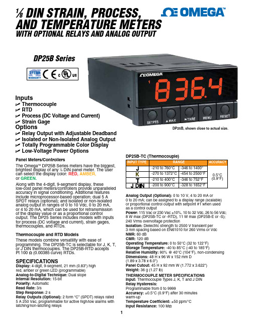
InputsU Thermocouple U RTDU Process (DC Voltage and Current)U Strain GageOptionsU Relay Output with Adjustable Deadband U Isolated or Non-Isolated Analog Output U T otally Programmable Color Display U Low-Voltage Power OptionsSPECIFICATIONSDisplay: 4-digit, 9-segment, 21 mm (0.83") high red, amber or green LED (programmable)Analog-to-Digital Technique: Dual slope Internal Resolution: 15-bit Polarity: Automatic Read Rate: 3/sStep Response: 2 sRelay Outputs (Optional): 2 form “C” (SPDT) relays rated 5 A 250 Vac, programmable for active high/low alarms with latching/non-latching relaysAnalog Output (Optional): 0 to 10 V, 4 to 20 mA or0 to 20 mA; can be assigned to a display range (scalable) or proportional control output with setpoint #1 when used as a control outputPower: 115 Vac or 230 Vac ±10%, 10 to 32 Vdc, 26 to 56 Vdc; 8 W max (DP25B-TC or -RTD), 11 W max (DP25B-E or -S); 240 Vrms overvoltage protectionIsolation: Dielectric strength to 2500 V transient per 3 mm spacing based on EN61010 for 260 Vrms or Vdc NMR: 60 dB CMR: 120 dBOperating Temperature: 0 to 50°C (32 to 122°F)Storage Temperature: -40 to 85°C (-40 to 185°F)Relative Humidity: 90% @ 40°C (104°F), non-condensing Dimensions: 48 H x 96 W x 152 mm D (1.89 x 3.78 x 6.0")Panel Cutout: 45 H x 92 mm W (1.772 x 3.622")Weight: 36 g (1.27 lb)THERMOCOUPLE METER SPECIFICATIONS Input: Thermocouple Types J, K, T and J DIN Relay Hysteresis:Programmable from 0 to 9999Accuracy: ±0.5°C (0.9°F) after 30 minutes warm-upTemperature Coefficient: ±50 ppm/°C Input Resistance: 100 M ΩPanel Meters/ControllersThe Omega TM DP25B Series meters have the biggest, brightest display of any 1⁄8 DIN panel meter. The user can select the display color: RED, AMBER, or GREEN.Along with the 4-digit, 9-segment display, theselow-cost panel meters/controllers provide unparalleled accuracy in signal conditioning. Additional features include microprocessor-based operation; dual 5 A SPDT relays (optional); and isolated or non-isolated analog output in ranges of 0 to 10 Vdc, 0 to 20 mA, or 4 to 20 mA, which can be used for retransmission of the display value or as a proportional controloutput. The DP25 Series includes models with inputs for process (DC voltage and current), strain gages, thermocouples, and RTDs.Thermocouple and RTD ModelsThese models combine versatility with ease ofprogramming. The DP25B-TC is selectable for J, K, T, or J DIN thermocouples. The DP25B-RTD accepts Pt 100 Ω (0.00385 curve) RTDs.1⁄8 DIN STRAIN, PROCESS,AND TEMPERATURE METERSWITH OPTIONAL RELAYS AND ANALOG OUTPUTDP25B, shown close to actual size.DP25B SeriesSTRAIN, PROCESS, AND TEMPERATURE METERSDP25B-TC, programmed foroptional green display, shown actual size.Process and Strain ModelsBecause they accept a wide range of DC voltage and current inputs, the DP25B-E strain meters can handle most process and strain applications. Features include easy front-panel scaling to virtually any engineering units, a remote tare function for weighing applications, and a hardware lockout to prevent unauthorized changes in setup. In addition, the DP25B-E meters feature built-in excitation in 4 user-selectable voltages, which makes them compatible with most transducers and transmitters.SPECIFICATIONS(Process and Strain Meters/Controllers)Input Ranges: 0 to 100 mV, ±50 mV, 0 to 10V, ±5V, 0 to 20 mA, 4 to 20 mAProtection: 240 Vrms max for voltage input ranges; 200 mA for current rangesInput Impedance: 100 M Ω for 100 mV or ±50 mV range; 1 M Ω for 10V or ±5V range; 5 Ω for 20 mA current inputAnalog-to-Digital Technique: Dual slope Internal Resolution: 15-bit Polarity: AutomaticMax Error Strain/Process: ±0.03% rdgSpan Temperature Coefficient: ±50 ppm/°C Warm-Up to Rated Accuracy: 30 minExcitation Voltage: 24V @ 25 mA or 12V @ 50 mA; 10V @ 120 mA or 5V @ 60 mASPECIFICATIONS(RTD Temperature Meter/Controller)Input: RTD 100 Ω Pt (0.00385 curves);2-, 3- and 4-wire selectableAccuracy: ±0.5°C (0.9°F) after 30 min warm-up Temperature Coefficient: ±50 ppm/°C Input Resistance: 100 MΩSelect Your Color!The Omega TM DP25B Series meters and controllers have totally programmable color displays—for RED , AMBER, or GREEN .Program to Display in RED ,AMBER, or GREEN .Totally Programmable Color DisplaysDP25B-RTD (RTD)PROCESS AND STRAIN METERSComes complete with operator’s manual.Ordering Examples: DP25B-TC-DC10/32-AR, thermocoupleindicator for J, K, T or J DIN input, low-voltage power, analog output and dual 5 A relays.DP25B-E, process meter.Custom firmware and hardware available in quantity.1. Pollution Degree 2。
DR系列功率驱动器使用说明
e. FO(故障输出参数):有故障时 IPM 低电平输出电流为 10mA,宽度为 1.8mS 的脉冲信号, 在此期间系统必须做 出反应,停机检查,否则循环输出故障信号容易打坏模块。
f.过压保护信号建议设置在>400V 时。
10.开关电源性能指标:
6
输入直流:170-500V; 额定功率:60W; 输出 5V:300mA,最大 1A;
概述:
DR 系列功率驱动器,它集 IPM,开关电源,高速光耦,保护电路,吸收电路,外围接口,散热器于一体,采用国际 标准工艺定制而成的全功能驱动器。该产品技术成熟,性能稳定,开发方便,功能完善,通用性强,是纺织机械, 食品机械,注塑机,风机,变频电源,交直流伺服,无刷电机驱动器等产品的理想开发平台。
24V:2A; ±15V:200mA; 15V*3: 150mA(上三桥每路用) 15V*1:300mA(下三桥共用) 30-50V 直流取样:100mA; 设计要点: 1) 所有电源输出到用户控制板终端均需加滤波电容和去耦电容以消除毛刺。 2) 用户控制板的所有 PWM 信号线需要上拉 10K 电阻,做低有效处理。 3) 死区电平必须为高。 4) 假负载可以用功率相同的灯泡用三角型接法观测电流电压变化。 5) 禁止使用示波器探头测试光耦后级波形,在运行中禁止任何板上测试。
典型:R(25℃)=5.000kΩ
阻值-温度特性表
温度℃ -20 -19 -18 -17 -16 -15 -14 -13 -12 -11 -10 -9 -8 -7 -6 -5 -4 -3 -2 -1 0 1
阻值 KΩ 37.49 35.53 33.76 32.09 30.52 29.03 27.62 26.29 25.03 23.84 22.72 21.65 20.64 19.68 18.77 17.91 17.10 16.32 15.59 14.89 14.23 13.60
温度传感器使用说明
Executi ng division : Responsible division : Document type : Confidentiality status :HCN NVPTechnical Documentation InternalPrepared :Document state :08.02.2006 Czernietzki (NVP)Technology Transfer HCN PreliminaryChecked :09.02.2006 Czernietzki (NVP)FNC System BusinessThermistorsApproved :File:Revision :Language :Pages :09.02.2006 Czernietzki (NVP) TD-Thermistors-en-R001 001 en 1/19This document and its contents are the property of Hoppecke or its subsidiaries. This document contains confidential proprietary information. The reproduction,Document administration 文件管理Document History 文件记录VersionDateResponsibleReason of change001 08.02.2006 Czernietzki First release of the document.Change justifiable 变更审核Hans-Peter Czernietzki NVPPreparing , Checking , ApprovingLewis Liu HCN QS Preparing , Checking , ApprovingDocument generated with following tools 使用下列工具编写文件:WORD 200 <Grafic tool>Content 目录1 Overview Thermistors........................................................................................................................................................................2 1.1 General.....................................................................................................................................................................................2 1.2 NTC Thermistors.....................................................................................................................................................................4 1.3 PTC Thermistors......................................................................................................................................................................5 1.4 Lead wire configurations..........................................................................................................................................................6 1.5 Available temperature probe....................................................................................................................................................8 1.6 Available connection cables.....................................................................................................................................................8 2 Designs...............................................................................................................................................................................................9 2.1 Stainless steel block version.....................................................................................................................................................9 2.2 Electrolyte version...................................................................................................................................................................9 2.3 Connection cables..................................................................................................................................................................10 2.3.1 Two wire connection 414 220 0802.............................................................................................................................10 2.3.2 Four wire connection 414 220 0804............................................................................................................................10 2.3.3 Connection clamp........................................................................................................................................................10 2.4 Temperature curve PT100B...................................................................................................................................................11 2.5 Temperature curve NTC10K..................................................................................................................................................11 2.6 Technical data NTC10K.........................................................................................................................................................11 3 Attachments......................................................................................................................................................................................11 3.1 Drawing 2BZ60287-01..........................................................................................................................................................11 3.2 Drawing 3BZ60731-01..........................................................................................................................................................11 3.3 Drawing 2BZ60287-02..........................................................................................................................................................11 3.4 Drawing 3BZ60407-01..........................................................................................................................................................11 3.5 Drawing 3BZ60732-01..........................................................................................................................................................11 3.6 Drawing 3BZ60407-02. (11)1 Overview Thermistors电热调节器简介1.1 General总则Resistance elements come in many types conforming to different standards, capable of different temperature ranges, with various sizes and accuracies available. But they all function in the same manner: each has a pre-specified resistance value at a known temperature which changes in a predictable fashion. In this way, by measuring the resistance of the element, the temperature of the element can be determined from tables, calculations or instrumentation. These resistance elements are the heart of the RTD (Resistance Temperature Detector or short: Thermistor). Generally, a bare resistance element is too fragile and sensitive to be used in its raw form, so it must be protected by incorporating it into an housing.电阻元器件满足不同的标准,能够适用不同的温度范围,可满足多种尺寸和精度要求。
FX2N系列可编程控制器

图3-2为基本单元型号各组成部分的含义说明。扩展 单元及扩展模块型号构成与基本单元雷同,只是在模块区 分部分中用“E”代替“M”。
5
第一节 FX2N系列可编程控制器及其性能指标
输入输 输入 输出 出总点 点数 点数
负载
享;8A/8点共享
0.3A/1点 0.8A/4点
0.5A/1点 0.8A/4点
感性负载
80V·A
15V·A/AC 100V
12W/DC24V
30V·A/AC 200V
灯负载
100W
30W
1.5W/DC24V
开路漏电流
—
1mA/AC 100V 0.1mA以下/
2mA/AC 200V
DC30V
响应 OFF到
FX2N-422-BD FX2N-485-BD
RS422通讯板 RS485通讯板
— —
板 FX2N-232-BD RS232通讯板
—
FX2N-CNV- 连接特殊适配器的功能扩展板
—
BD
特 FX0N-3A
殊 模 板
FX0N-16NT FX0N-4AD
FX0N-4DA
2ch模拟输入、1ch模拟输出 — 8 —
可编程控制器应用技术
第三章 FX2N系列可编程控制器
目录
FX2N系列可编程控制器及其性能指标 FX2N系列可编程控制器的安装及接线 FX2N系列可编程控制器编程软元件及功能 FX2N系列可编程控制器的基本指令 编程规则及注意事项
1
内容提要
FX2N系列可编程控制器是三菱公司小型PLC的代表产品 之一。本章介绍FX2N系列PLC的外观、接线、编程元件及 基本指令,为学习FX2N系列PLC的工业应用打下基础。
ABB温度传感器说明书
Ol/TSP_ZH
3.1 3.2 3.3 4
温度传感器设计 温度插芯设计 功能
12 11 11 14 14 15 17 17 17 17 17 17 17 17 18 19 20 21
SensyTemp TSP1X8 温度传感器系列 4.1 4.2 4.3 接线盒 支撑管 工艺连接 4.3.1 SensyTemp TSP128 温度传感器 焊入式/插入式安装护套 螺纹连接安装护套 法兰连接安装护套
1.11
电气安装安全提示
设备电气连接必须参照电气图由授权的专业人员完成。 遵循本手册中的电气连接说明,以确保电气保护有效。 连接设备必须完全满足安全隔离基本要求才能保证对危险电路的隔离,达到 安全保护的目的。 为保证隔离安全,可对易发生触电事故的电路单独供电或者提供额外的隔离 保护。
1.12
操作安全提示
位置: 1 /Titelblätter / Copyright/DB/Temperatur/TSP3X1 @ 20\mod_1211288113249_3101.doc @ 194539 @
操作说明书
Ol/TSP_ZH
温度传感器 SensyTemp TSP1X8
分销商: 上海卓乔仪表有限公司 上海市宝山区金勺路 1508 号 电话:021 – 36550515 13918149708 传真:021 – 56618080
2.
2.1 2.2
防爆环境中使用
保护等级
温度传感器的连接部件安装应满足最低防爆使用要求。
温度级别
本温度传感器应用的温度级别为 T6。如果现有爆炸气体环境指定的温度级别 为 T5、T4、T3、T2或 T1,则该温度传感器可在相应更高的温度级别条件下 使用。
2.3 2.4
温度传感器的使用方法

温度传感器的使用方法
温度传感器是一种测量温度变化的设备,使用方法如下:
1. 打开温度传感器的包装盒,取出传感器。
2. 将传感器插入测量对象中,通常情况下,传感器与测量对象接触的表面应该是平整的,并要避免传感器与任何物体相互接触。
3. 确认传感器与测量对象接触良好,然后将传感器插入温度计或温度计显示屏的插头。
4. 启动温度计,并设置合适的温度范围和单位。
然后读取屏幕上显示的温度数值。
5. 按需调整设置,如需要重新设置温度单位或调整范围等。
如果需要存储数据,可以将数据通过连接电脑的数据接口进行传输,保存到电脑上。
6. 使用完毕后,将传感器从测量对象中拔出,将其回收到包装盒中。
温度传感器可以广泛应用于实验室科研、医疗、食品安全等领域,需要注意在使用过程中保持设备的干燥、整洁,避免过度曝气、污染和损坏。
温湿度传感器使用说明书

NO:S1*******使用说明书温湿度传感器目录1、产品介绍 (1)1.1概述 (1)1.2功能特点 (1)1.3外观尺寸 (1)2、性能参数 (2)3、使用方法 (4)3.1系统框架图 (4)3.2安装说明 (6)4、通信协议 (9)4.1通讯基本参数 (9)4.2数据帧格式定义 (9)4.3通讯基本参数 (11)4.4通讯协议示例以及解释 (12)5、常见问题及解决方法 (14)6、保养维护 (15)7、运输存储 (16)7.1运输要求 (16)7.2存储要求 (16)8、订货服务 (17)8.1订货方法 (17)8.2客户服务 (17)1产品介绍1.1概述本(系列)产品可在线监测环境温度和湿度信息,广泛用于开关柜仪表室、断路器室、电缆室等处的环境温湿度在线监测。
采用进口工业级微处理器芯片、进口高精度温度传感器,确保产品高精度和可靠性。
1.2功能特点◆进口的测量单元,测量精准。
◆专用的485电路,通信稳定。
◆宽电压范围供电,安装方便。
1.3外观尺寸(单位:mm公差:±0.5)2性能参数3使用方法3.1系统框架图本产品也可以多个传感器组合在一条485总线使用,理论上一条总线可以接254个485传感器,另一端接入带有485接口的PLC 、通过485接口芯片连接单片机,或者使用USB转485即可与电脑连接,使用我公司提供的传感器配置工具进行配置和测试(在使用该配置软件时只能接一台设备)。
3.2安装说明3.2.1注意事项1、传感器应尽量垂直放置,保证安装墙面时,温湿度探头在传感器本体的下方(传感器本体上的字体为正方向)。
2、安装高度为人体坐高或主要测量的环境区域。
3、避免在易于传热且会直接造成与待测区域产生温差的地带安装,否则会造成温湿度测量不准确。
4、安装在环境稳定的区域,避免直接光照,远离窗口及空调、暖气等设备,避免直对窗口、房门。
5、尽量远离大功率干扰设备,以免造成测量不准确,如变频器/电机等。
二氧化碳温湿度传感器 室内型 操作手册说明书

操作手册二氧化碳温湿度传感器室内型目录安全注意事项接线图尺寸图软件规划操作流程保养及异常处理安全注意事项●使用本产品之前,用户必须阅读本用户手册的详细信息,然后按照正确的步骤使用本产品。
●使用设置本产品时,本用户手册仅供参考,并且需要妥善保存。
●操作使用上的限制,敬请注意!本产品不适用于防爆区域,请勿在有碍人身安全的情况下使用本产品。
●用于无尘室、动物饲养室等,有可靠性,控制精度等方面的特别要求时,请向本公司的销售人员咨询。
●如果用户将本产品安装在无尘室,动物繁殖环境等特殊环境中,请向本公司的专业销售人员进行专门的产品咨询。
●如果因操作人员不当或环境不正确而导致不正确和危险的后果,本公司将不承担任何法律责任。
警告!●安装前请确认产品是否因运送过程导致外观损坏,或因附件遗失影响产品功能。
●请将本产品安装在本说明书中明确规定的使用环境中使用,否则因此发生故障。
●请在切断供应电源的状态下进行接线作业,否则可能触电及造成设备故障。
●为防止产品损坏,在进行任何接线和安装之前,请务必断开产品的电源。
●请在本说明书规定的额定电源及各工作范围内使用本产品,否则可能引起火灾或设备故障。
●本产品必须在手册规定的操作条件下操作,以防止设备损坏。
●为安全起见,必须由电气安装专业人员配备仪表进行安装和接线,根据所适用的安全标准规范,所有接线必须遵守当地的室内布线规范和电气安装规则。
●关于接线,请按照内部接线规程,电气设备技术标准进行施工,所有接线必须符合室内接线规则和电气安装规则,并需将上盖螺丝及出线端迫紧,才能达到产品等级。
●为防止变频器等的干扰,避免错误信号导致产品损坏,请使用绝缘导线。
●电线的末端请使用有绝缘覆盖的压接端子,及依照接线图方式施工,避免引起短路。
●为避免人身伤害,请勿触摸正在使用的产品的运动部件。
●产品故障时,可能因无输出导致高湿环境状态,或可能使输出高过,请在控制器侧采取安全措施。
●丢弃本产品时,用户必须遵守不同国家地区有关工业生活垃圾的相关规定。
msts-ir 螺纹式红外温度传感器 hart 使用手册说明书
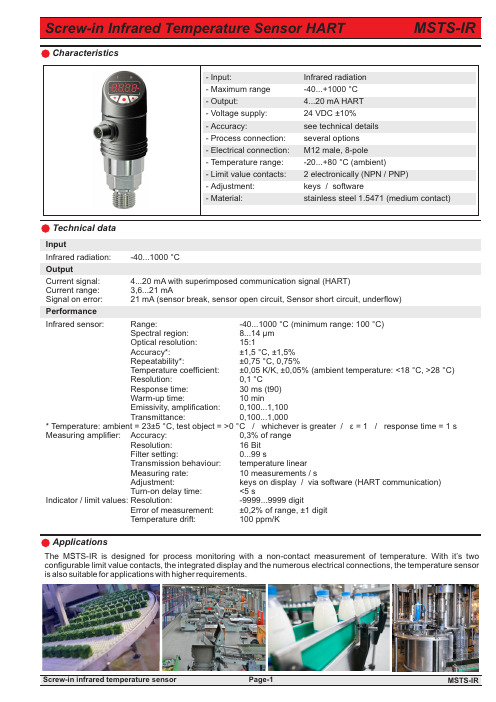
ApplicationsTechnical dataCharacteristicsInputInfrared radiation: -40...1000 °C OutputCurrent signal: 4...20 mA with superimposed communication signal (HART)Current range: 3,6...21 mA Signal on error: 21 mA (sensor break, sensor open circuit, Sensor short circuit, underflow)Performance Infrared sensor: Range: -40...1000 °C (minimum range: 100 °C) Spectral region: 8...14 µm Optical resolution: 15:1 Accuracy*: ±1,5 °C, ±1,5% Repeatability*: ±0,75 °C, 0,75% Temperature coefficient: ±0,05 K/K, ±0,05% (ambient temperature: <18 °C, >28 °C) Resolution: 0,1 °C Response time: 30 ms (t90) Warm-up time: 10 min Emissivity, amplification: 0,100...1,100 Transmittance: 0,100...1,000* Temperature: ambient = 23±5 °C, test object = >0 °C / whichever is greater / ε = 1 / response time = 1 s Measuring amplifier: Accuracy: 0,3% of range Resolution: 16 Bit Filter setting: 0...99 s Transmission behaviour: temperature linear Measuring rate: 10 measurements / s Adjustment: keys on display / via software (HART communication) Turn-on delay time: <5 s Indicator / limit values: Resolution: -9999...9999 digit Error of measurement: ±0,2% of range, ±1 digit Temperature drift: 100 ppm/KThe M S TS-IR is designed for process monitoring with a non-contact measurement of temperature. With it’s two configurable limit value contacts, the integrated display and the numerous electrical connections, the temperature sensor is also suitable for applications with higher requirements.6,5S (mm)0D (mm)8,375101501522520300253753045035525406004567550750558256090065975701050Technical data (continued)Optical chartsIndication Display: 7 segment, 8,5 mm, red, 4 digits, representation mirror-inverted 180° possible Head of display: rotatable approx. 330°Memory: minimum / maximum values Indication: - measuring value - unit of measurement - control menu Decimal point: automatically or manually, dependent on measuring range / unit Limit contacts Electronically: 2x PNP or NPN (30 VDC, 200 mA) Option: 2x PNP or NPN (30 VDC, 1000 mA)Indication: 1 LED red for each limit value Voltage across: <1 V Settings: with 3 keys (TouchM-Technology)Setting range: switch point and hysteresis: any value within measuring range Switching delay: 0,0...999,9 s Failsafe function: adjustable Galvanical insulation: switching outputs are separated from measuring amplifier Supply Voltage: 24 VDC ±10%Reverse battery protection: available (no function, no damage)Ambient conditions Temperature: Operating range: -20...+80 °C Sensing head: -20...120 °C Storing: -40...+85 °C Air humidity: 10...95% rH (no condensation)MechanicsDimensions: see page 3Process connection: 1/2” / 3/4” / 1” / 1/2NPT Electrical connection: M12 male, 8-pole Material: Process connection: stainless steel 1.4571 Sensing head: stainless steel Body: PBT GF30 Head of display: polycarbonate (makrolon)Weight: approx.240 g Fitting position: any (avoid deposition on optics)System pressure: 0 bar (barometric pressure)Protection of device: Ingress protection: at least IP 65 (electronics) PCB: potted Vibration: IEC 68-2-6: 3G, 11 – 200 Hz, any axis Shock: IEC 68-2-27: 50G, 11 ms, any axis Programmable featuresMeasuring amplifier: Measuring range start (LRV) / M easuring range end (URV) / Adjustment, simulation of output current / Filter function / Linear output signal / HART address / 2-point calibration Display: range of indication / time of indication / decimal point / units / stabilisation of zero point / locking of programming / calibration points / TAG number Limit value contacts: limit value 1 and 2 / hysteresis 1 and 2 / delay times 1 and 2Features, Operation: according VDMA 24574-1 up to 24574-4S = Spot sizeD = Distance from front of the sensing head to the objectFor valid measurement the spot size should be as large as the object or smaller.Electrical connectionExample of electrical connectionM S TS-IR1) Measuring range: / Indicating range2) All settings, which are possible according the technical data, can be selected. For not given values the details offactory-set are u sed.HART CommunicationThe HART-Tool is a graphical user interface for the ME series with menu-driven progam for configuration. It c an b e used for putting into operation, configuration, analysis of signals, data backup and documentation of t he device. Operating systems: Windows 2000, XP, Windows 7 und 8.1Connection via HART interface (modem) with USB interface of a PC or hand-held HART communicator Settings: - Adjustment of output current - Simulation of output current - Filter function - Limits of measuring range - Linear output signal - HART address- HART TAG number - 2-point calibrationPlease note:When using communication via a HART modem, a comunication resistance of 250 Ω has to be taken into account.。