WRT-R2系统分机安装使用说明书WPZS-212B A3
RSW-2 Breeder 使用和维护手册说明书
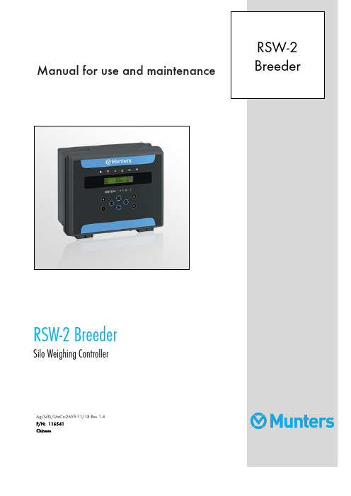
Manual for use and maintenance RSW-2 BreederSilo Weighing ControllerAg/MIS/UmCn-2659-11/18 Rev 1.4P/N: 116541ChineseRSW-2 BreederManual for use and maintenanceRevision: 1.4 of 07.2022Ag/MIS/UmCn-2659-11/18 Rev 1.2 (MIS)发布日期: Version 7.04该使用和维护手册与附带的技术文档是设备的重要组成部分.该文档专为设备的使用者使用:在没有系统装配者的预先授权下,整个文档或文档的任一部分都不能进行复制、作为文件存入电脑内存或传送至第三方.蒙特保留在依照技术和法律的发展下对设备进行有效更改的权利.索引1简介-------------------------------------------------------------------------------------------------------------------------------------------------------------------------- 51.1免责声明---------------------------------------------------------------------------------------------------------------------------------------------------------------------- 51.2介绍--------------------------------------------------------------------------------------------------------------------------------------------------------------------------------- 51.3备注--------------------------------------------------------------------------------------------------------------------------------------------------------------------------------- 5 2预防措施---------------------------------------------------------------------------------------------------------------------------------------------------------------- 62.1接地--------------------------------------------------------------------------------------------------------------------------------------------------------------------------------- 62.2定期检查电池----------------------------------------------------------------------------------------------------------------------------------------------------------- 6 3RSW-2种鸡版料塔称重控制器介绍--------------------------------------------------------------------------------------------------------- 73.1显示--------------------------------------------------------------------------------------------------------------------------------------------------------------------------------- 73.2键盘--------------------------------------------------------------------------------------------------------------------------------------------------------------------------------- 83.3热键--------------------------------------------------------------------------------------------------------------------------------------------------------------------------------- 93.4系统描述------------------------------------------------------------------------------------------------------------------------------------------------------------------- 103.5输出描述------------------------------------------------------------------------------------------------------------------------------------------------------------------- 103.6料斗阀门输出-------------------------------------------------------------------------------------------------------------------------------------------------------- 113.7料线输出(公、母、公母)[料盘] -------------------------------------------------------------------------------------------------------- 123.8灯光------------------------------------------------------------------------------------------------------------------------------------------------------------------------------ 12 4初始设置-------------------------------------------------------------------------------------------------------------------------------------------------------------- 134.1预设置 ------------------------------------------------------------------------------------------------------------------------------------------------------------------------ 134.2校准------------------------------------------------------------------------------------------------------------------------------------------------------------------------------ 134.2.1用已知重量校准料塔 (14)4.2.2通过卡车添料过程校准 (14)4.2.3料塔1/2称重因数 (14)4.3配置------------------------------------------------------------------------------------------------------------------------------------------------------------------------------ 154.3.1系统参数 (15)4.3.2系统参数解释 (16)4.3.3继电器功能 (17)4.3.4料塔布局 (17)4.4测试------------------------------------------------------------------------------------------------------------------------------------------------------------------------------ 184.4.1继电器 (18)4.4.2料塔1/2 (18)5使用控制器--------------------------------------------------------------------------------------------------------------------------------------------------------- 195.1控制------------------------------------------------------------------------------------------------------------------------------------------------------------------------------ 195.1.1公/母鸡添料 (19)5.1.2饲料周期 (20)5.1.3公/母鸡喂料 (20)5.1.4灯光 (20)5.1.5保存/复位 (20)5.2管理------------------------------------------------------------------------------------------------------------------------------------------------------------------------------ 215.2.1料塔1/2存量 (21)5.2.2时间/日期 (21)5.2.3生长日 (21)5.2.4新群 (21)5.2.5报警重置 (21)5.2.6报警时间 (21)5.3历史------------------------------------------------------------------------------------------------------------------------------------------------------------------------------ 225.3.1公/母鸡消耗 (22)5.3.2料塔1/2 存量/装载 (22)5.3.3报警 (23)5.3.4事件 (23)5.3.5上批 (23)6配置说明-------------------------------------------------------------------------------------------------------------------------------------------------------------- 246.1环境保护------------------------------------------------------------------------------------------------------------------------------------------------------------------- 24 7安装------------------------------------------------------------------------------------------------------------------------------------------------------------------------ 257.1料塔安装指南-------------------------------------------------------------------------------------------------------------------------------------------------------- 257.1.1安装样本 (25)7.1.2称重元件测试步骤 (26)7.2RSW-2接线-------------------------------------------------------------------------------------------------------------------------------------------------------------- 267.2.1RSW-2 Breeder 通信接线图 (31)8质保(请勿翻译)------------------------------------------------------------------------------------------------------------------------------------------ 321简介1.1免责声明Munters 保留在本文件发行之后,因生产或其他原因而更改规格、数量、尺寸等的权利。
Power XpertTM UX12户内金属铠装移开式开关设备 安装操作及维护手册说明书
IB022006SCPower Xpert TM UX12户内金属铠装移开式开关设备安装操作及维护手册201292011前言 . . . . . . . . . . . . . . . . . . . . . . . . . . . . . . . . . . . . . . . . . .产品使用说明 . . . . . . . . . . . . . . . . . . . . . . . . . . . . . . . . . . .现场安装操作规程 . . . . . . . . . . . . . . . . . . . . . . . . . . . . . . .通电运行前的检查及调试 . . . . . . . . . . . . . . . . . . . . . . . . . .开关柜的维护检修 . . . . . . . . . . . . . . . . . . . . . . . . . . . . . . .附录 . . . . . . . . . . . . . . . . . . . . . . . . . . . . . . . . . . . . . . . . . .目录描述页码1257791 伊顿公司 /electrical产品说明书 IB022006SC2012年9月版Power Xpert TM UX12户内金属铠装移开式开关设备安装操作及维护手册敬请注意前言概述1. 严禁将该产品在超出其自身技术条件的情况下运行。
2. 严格遵照国家及地方颁布的安全施工操作规程。
3. 严格遵循本安装操作手册中的相关规定。
4. 妥善保管此安装操作手册,以便安装、操作、维护人员随时查阅。
伊顿电力设备有限公司是美国伊顿电气集团旗下的一家全资公司,是国家机械部、能源部定点生产高、低压成套开关设备的专业厂家。
多年 来,公司凭借卓越的产品、优质的服务、科学的管理不断赢得国内市 场;并以超群的胆识、迅猛的发展速度、优异的业绩在全国电器同行业中异军突起。
腾达W302R无线宽带路由器安装设置使用说明书之配置指南
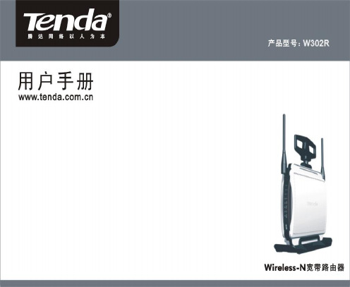
版权申明是深圳市吉祥腾达科技有限公司注册商标。
文中提及到的其它商标或商品名称均是他们所属公司的商标或注册商标。
本产品的所有部分,包括配件和软件,其版权属深圳市吉祥腾达科技有限公司所有,在未经过深圳市吉祥腾达科技有限公司许可的情况下,不得任意拷贝、抄袭、仿制或翻译成其它语言。
本手册中的所有图片和产品规格参数仅供参考,随着软件或硬件的升级会略有差异,如有变更,恕不另行通知,如需了解更多产品信息,请浏览我们的网站:http://目录第1章:产品介绍 (1)第2章:认识Wireless-N宽带路由器 (2)后面板接口说明及图示 (2)前面板图示及说明 (3)硬件安装 (4)第3章:连接到宽带路由器 (5)正确设置您的计算机网络配置 (5)验证网络正常连接 (8)登陆路由器 (10)第4章:基本配置 (11)设置向导 (11)第5章:高级设置 (15)LAN口设置 (15)WAN 设置—虚拟拨号(PPPoE) (16)WAN口设置—静态IP (17)MAC地址克隆 (18)域名服务器设置 (19)第6章:无线设置 (20)无线模式 (19)基本设置 (20)无线安全设置 (24)WPS 设置 (30)WDS 设置 (30)无线高级设置 (31)第7章:DHCP服务设置 (34)DHCP 客户端列表 (35)第8章:虚拟服务器 (35)单端口映射 (35)端口段映射 (38)端口触发 (38)ALG应用 (40)DMZ 主机 (41)UPnP 设置 (43)第9章:带宽控制 (43)第10章:安全设置 (44)客户端过滤 (45)URL 过滤 (46)MAC 地址过滤 (48)防网络攻击 (48)远端WEB管理 (49)本地WEB管理 (50)WAN口Ping (51)第11章:路由设置 (51)路由表 (51)静态路由 (52)第12章:系统工具 (53)时间设置 (53)动态DNS (53)备份/恢复设置 (55)重启路由器 (58)修改登录口令 (58)系统日志 (59)附录:产品特性 (59)第1章:产品介绍感谢您购买W302R Wireless-N宽带路由器(以下简称路由器)。
tp-link tl-er2200g 千兆企业vpn路由器安装手册说明书

Enterprise Networking Solution安装手册多W A N口千兆企业V P N路由器TL-ER2200G声明Copyright © 2022 普联技术有限公司版权所有,保留所有权利未经普联技术有限公司明确书面许可,任何单位或个人不得擅自仿制、复制、誊抄或转译本手册部分或全部内容,且不得以营利为目的进行任何方式(电子、影印、录制等)的传播。
为普联技术有限公司注册商标。
本手册提及的所有商标,由各自所有人拥有。
本手册所提到的产品规格和资讯仅供参考,如有内容更新,恕不另行通知。
除非有特殊约定,本手册仅作为使用指导,所作陈述均不构成任何形式的担保。
I声明相关文档除本安装手册外,我们还提供以下文档的电子版本。
如需获取最新产品资料,请登录安装手册简介《千兆企业VPN路由器安装手册》主要介绍了路由器的硬件特性、安装方法以及在安装过程中应注意事项。
本手册包括以下章节:第1章:产品介绍。
简述路由器的基本功能特性并详细介绍外观信息。
第2章:产品安装。
指导路由器的硬件安装方法以及注意事项。
第3章:硬件连接。
指导路由器与其他设备之间的连接及注意事项。
第4章:配置指南。
介绍登录路由器WEB管理系统和云管理路由器的方法。
附录A:常见故障处理。
附录B:技术参数表格。
附录C:产品保修说明。
II相关文档III阅读对象附录D:有毒有害物质含量声明。
说明:在安装设备之前及安装设备过程中为避免可能出现的设备损坏及人身伤害,请仔细阅读本手册相关内容。
阅读对象本手册适合下列人员阅读:网络工程师网络管理人员约定本手册以下部分,产品相关视图仅为示意,请以实际机型为准,如无特别说明,均以TL-ER2200G为例介绍,所提到的路由器是指多WAN口千兆企业VPN路由器。
本手册采用了如下几种醒目标志来表示操作过程中应该注意的地方,这些标志的意义如目录第1章 产品介绍 —————————————011.1 产品简介 (01)1.2 产品外观 (01)第2章 产品安装 —————————————032.1 物品清单 (03)2.2 安装注意事项 (03)2.3 安装工具准备 (05)2.4 产品安装 (05)第3章 硬件连接 —————————————073.1 连接线缆 (07)3.2 连接电源 (08)3.3 设备初始化 (08)3.4 安装后检查 (08)第4章 配置指南 —————————————094.1 WEB管理 (09)4.2 云管理 (12)附录A 常见故障处理 ———————————13附录B 技术参数规格 ———————————14附录C 产品保修说明 ———————————17附录D 有毒有害物质声明 ————————18IV目录千兆企业VPN路由器安装手册01产品介绍第1章 产品介绍1.1 产品简介TP-LINK千兆企业VPN路由器系列产品主要定位于中小型企业、网吧、社区、酒店等网络环境,支持VPN、上网行为管理、AP管理、接入认证、防火墙、带宽控制、多WAN口负载均衡等丰富的功能特性,适合组建高速、安全且易管理的企业网络。
1002 212 025说明书

Safety Information . . . . . . . . . . . . . . . . . . . . . . . . . . . . . . . . . . 2 Warranty . . . . . . . . . . . . . . . . . . . . . . . . . . . . . . . . . . . . . . . . . . 3 Pre-Installation . . . . . . . . . . . . . . . . . . . . . . . . . . . . . . . . . . . . . 3 Installation . . . . . . . . . . . . . . . . . . . . . . . . . . . . . . . . . . . . . . . . 6Before you begin, carefully read and understand the instructions in this manual. Please follow the instructions in the order presented inthis manual and observe all warnings and cautions.This mount has been tested to support a television with a minimum of 20 in. (51 cm) and a maximum 56 in. (142 cm)diagonal screen and a weight up to 80 lbs. (36 kgs).The manufacturer warrants that it will replace or repair this item, free of charge, at the manufacturer’s sole discretion, should it prove defective in materials or workmanship.This warranty does not apply to:□Normal wear and tear□Friction damage□Coating defects□Defects caused by loosened screws, nuts, or bolts□Improperly mounting the bracket to the wall□Improperly installing the bracket to the display□Failure to properly follow installation instructions□Modifi cation or repairs not made or authorized by the manufacturer□Loading beyond permitted load□Intentional misuseContact the Customer Service Team at 1-877-527-0313 or visit .PLANNING INSTALLATIONCompare all parts in the package with the Hardware Included and Package Contents lists in this manual. If any part is missing or damaged, do not install this wall mount system and call customer service at 1-877-527-0313 or visit .This wall mount bracket is compatible with VESA 100/200/300/400 mm mounting holes.PLANNING WALL PLACEMENTWhen selecting a wall to mount your display, keep the following in mind:□Select a place with easy access to power outlets, cable input sources, and connections for speakers and accessories.□Avoid direct sunlight, heat, and vibrations and do not place in direct fl ow of traffi c.□Select a weight-bearing wall. The wall must be able to safely support four times the combined load of the equipment and all attached hardware and components.PLANNING MOUNTING HEIGHTThe optimal viewing height is to center the display at eye level when seated. Many people consider this to be too low for a wall mount, and commonly use the following rule for placement:□Position the bottom of the display no higher than eye level when seated, and the top of the display no higher than eye level when standing. Anything within these limits should normally provide a comfortable viewing experience.ENSURING WALL STABILITYCarefully inspect the wall area you have selected. Examine the wall surface before you begin drilling.□For concrete walls, check for damaged or loose concrete and do not drill in those areas. □For brick wall, never drill into the mortar between blocks.□For wood studs, locate the wall studs and drill in the center of the stud.TOOLS REQUIRED (NOT INCLUDED IN THE PACKAGING)Power drill5-32 in. (4 mm) wood drill bit or 3/8 in. (10 mm) masonry drillbitsPhillipsscrewdriverStud finderMeasuringtapePencil HammerHARDWARE INCLUDEDAA BB CC DD EEJJFF GG HH IIPACKAGE CONTENTS7 Attaching the mounting arm to the□Align the mounting arm holes with the pre-drilled holes in the wall.□Use the level (C) to ensure that the mounting arm (A) is level on the wall.□Attach the mounting arm (A) to the wall using lag bolts(BB). Tighten the bolts (BB) securely using a Phillipsscrewdriver and a socket tool (not included).8Attaching the mounting plate to theTV (VESA 100 and 200)This procedure describes how to attach the mounting plate to VESA 100 and 200 TVs. For VESA 300 and 400, proceed to step 9. □If necessary, align spacers (EE) or (FF) over the mounting holes on the back of your TV. □Position the wall plate (A) over the TV and attach using the appropriately sized bolts (CC or DD) and washers(GG or HH).EE/FFAGG/HHDD AGG/HH100x100 / 200x200100x100 / 200x200CC9Attaching the mounting plate to the TV (VESA 300 and 400)□Attach the left and right arm extenders (B1 and B2) to the wall plate (A) using M6 x 8 bolts (II). □Align spacers (EE or FF) over the mounting holes on the back of your TV. □Position the wall plate (A) with extenders (B) over spacers (EE or FF) and attach them to the TV using the appropriate sized bolts (CC or DD) and washers (GG or HH).CC II JJB1B2B1B2GG/HHDD EE/FFGG/HH12 Adjusting the angle of the TV□Adjust the angle of the TV by loosening the handle (1) on the wall plate assembly (A). Refer to the fi gure for the various angle adjustments. Securely tighten the handle (1) when you are fi nished.Questions, problems, missing parts? Before returning to the store, call Commercial Electric Customer Service8 a.m. - 7 p.m., EST, Monday-Friday, 9 a.m. - 6 p.m., EST, Saturday1-877-527-0313Retain this manual for future use.。
K2 K2Sprint 振动控制系统使用说明书
目录
第 1 章 系统构成................................................................. 1-1 1.1 硬件构成 ............................................................... 1-1 1.1.1 微机 ............................................................. 1-1 1.1.2 专用硬件 I/O 设备 ................................................ 1-3 1.2 硬件规格 ............................................................... 1-4 1.2.1 规格 ............................................................. 1-4 1.2.2 专用硬件 ......................................................... 1-9 1.3 软件构成 ............................................................... 1-12 1.3.1 OS部分 ......................................................... 1-12 1.3.2 应用软件部分 ..................................................... 1-12
3.3.3 极性............................................................. 3-2 3.3.4 初始输出电压的既定值 ............................................. 3-3 3.3.5 额定信息 ......................................................... 3-3 3.3.6 控制频率范围的限制 ............................................... 3-3 3.3.7 其他的控制量 ..................................................... 3-3 3.3.8 接点输出输入信息 ................................................. 3-3 3.4 输入环境信息 ........................................................... 3-4 3.4.1 输入环境信息名 ................................................... 3-4 3.4.2 通道名 ........................................................... 3-4 3.4.3 模块的 ID 和 Ch ................................................... 3-5 3.4.4 物理量 ........................................................... 3-5 3.4.5 输入类型 ......................................................... 3-5 3.4.6 输入灵敏度 ....................................................... 3-5 3.4.7 极性............................................................. 3-5 3.4.8 连接 TEDS ......................................................... 3-5 第 4 章 基本操作方法 ............................................................ 4-1 4.1 概要 ................................................................... 4-1 4.2 基本操作 ............................................................... 4-2 4.2.1 应用软件的启动 ................................................... 4-2 4.2.2 应用软件的结束 ................................................... 4-3 4.2.3 图标的说明 ....................................................... 4-5 4.2.4 文件操作 ......................................................... 4-8
Lorex LBV1521系列安装指南说明书
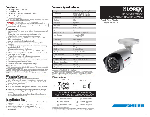
0.1 Lux without IR LED 0 Lux with IR LED
Video Output
Lorex Analog HD
Lens / Lens Type
3.6mm F1.9 / Fixed
FOV (Diagonal)
90°
Termination
BNC Type
IR LED Qty. / Type
Before installing the cameras:
• Decide whether to run the cables through the wall / ceiling (drilling required) or along the wall / ceiling.
• If you run the cables along the wall / ceiling, you must run the cable through the cable notch on the base. This will keep the camera base flush to the surface when mounted.
Operating Humidity Range
< 95% RH
Indoor/Outdoor***
Both (IP66)
Weight (including stand)
二线可视非可视主机说明书(数码主开)

二线可视非可视对讲系统(门口主机配用说明)安装使用手册主机为数码式主开适用目录●产品功能特点 (1)●安装及调试方法 (1)●常见故障及排除 (7)●系统接线图…………………………………………附●保修卡……………………………………………附注意事项:1.安装本系统之前,请仔细阅读使用手册,并妥善保管,以备参考查阅。
2.请遵守设备使用手册上的所有警告事项,按照使用手册的指示操作。
3.设备正常运行适宜温度为-15℃-50℃,在过冷或过热的环境中使用时,可能影响产品的性能。
4.注意防水,避免线路短路。
5.可视系统安装时,须注意可视主机摄像头的安装位置和照射角度,应尽量避免摄像头向阳和照射人体时图象背光的情况。
6.对设备进行接线时,请不要带电操作。
▲产品功能特点:1、系统最大容量可接500户室分机2、门口主机可呼叫本单元室分机,并与其双向通话。
3、具有每户室分机一个任意设置和更改开锁密码的功能4、门口主机设有自动故障检索程序,能及时检测出本主机任一分机的短路、断路、以及分机总线各线间的短路故障,并及时给出短路,断路故障的符号显示,同时切断与其他系统的信号连接,隔离故障5、房号编码灵活。
在主机键盘上可查找室分机码及再编制分机房号。
6、非可视二线入户、不分极性,安装方便。
7、可视具有视频自动放大功能,适合高层小区及多可视分机。
▲安装及调试方法:○安装方法:1、单元门口主机:先按安装尺寸在墙上或门上开出安装孔,然后把底壳用螺丝固定在墙上,然后把主机按接线图所示接线后,再用螺丝固定在底板上(装在门上的可使用所附配件将主机壳装在门上)。
2、室分机:先把分机背后的挂板取下,用螺丝固定在墙上,按接线图将线一一对应接好,然后把分机直接挂到挂板上,接上电源即可使用。
○调试方法:本系统主要是通过下表计算得出解码器的码编排,然后通过设定解码器地址码(权值),算出该解器第一个端口值,就可以得出该解码器中各个端口对应的码值,然后通过单元门口主机输入密码(##825836914)找到该码值对其设定一个四位数的房号,这样该解码器端口上所连接的室分机分房号就是你刚设定的房号了。
锐捷RSR10(20)系列路由器用户安装手册V1.81-10.3(5)

¾ 网络管理员
3
本书约定
1、通用格式约定 宋体:正文采用 5 号宋体。 楷体:警告、说明等提示等内容一律用楷体,并且在内容前后增加线条与正文隔离。
Terminal Display 格式:自定义的 Terminal Display 格式,英文 Courier New ,中文宋体,文字大 小 8.5 ,表示屏幕输出信息此外屏幕输出。信息中夹杂的用户从终端输入的信息,采用加粗字体表示。
锐捷网络客户服务中心可以为所有的客户提供所需要的技术帮助:产品、技术 和解决方案。对于客户遇到的产品的安装,软件的配置问题,以及其它的网络性能 的问题,客户服务中心都将提供迅速的技术支持。 ¾ 技术支持网站: ¾ 技术支持信箱:service@ ¾ 呼叫中心热线: 4008-111-000 ¾ 客户服务投诉热线:0591-83057315
®
锐捷 RSR10/RSR20 系列路由器 用户安装手册
V1.81
版权声明
福建星网锐捷网络有限公司©2000-2010
版权所有,保留一切权利。
本手册所有权益由福建星网锐捷网络有限公司独家拥有。没有
经过本公司书面许可,任何单位和个人不得擅自摘抄、复制本
书内容的部分或者全部,并且不得以任何形式传播。
福建星网锐捷网络有限公司保留以后对本手册描述的产品和手
建议: 建议由熟悉电气环境、线缆连接以及有实际安装和配置路由器经验的专业技术人员进 行安装和配置。
这份手册包括以下章节: z 第一章 产品介绍 介绍了锐捷 RSR10/RSR20 系列路由器的产品介绍以及系统特性。 z 第二章 安装路由器前的准备 描述了安装锐捷 RSR10/RSR20 系列路由器的环境要求、安装前和安装过程中需要注意的 事项、安装所需工具。 z 第三章 路由器的安装 介绍锐捷 RSR10/RSR20 系列路由器的机械安装方法、电源连接方法、备份口线缆连接方 法以及配置口线缆连接方法。 z 第四章 启动和配置路由器 介绍路由器初始启动信息及路由器进行的初始配置。 z 第五章 安装故障处理 介绍了如何处理安装过程中可能出现的问题及故障处理。 z 第六章 线缆使用说明 介绍了路由器常见配套线缆使用方法。
VISTA-120安装配置指南

第四章:
安装主机..........................................................................................................11 固定主机箱 ...................................................................................................... 11 安装电路板 ...................................................................................................... 11 电话线连接 ...................................................................................................... 12 连接交流变压器............................................................................................... 12 安装后备电池 ..................................................................................................13
第三章:
减少误警措施 ....................................................................................................9 外出错误逻辑 ....................................................................................................9 外出延时复位 ....................................................................................................9 交叉防区............................................................................................................ 9 呼叫等待失效 ..................................................................................................10
F2NAS-2中文快速安装指南

包装清单
在您开始使用前,请检查包装盒内是否包含下列的各个项目。
编号 1 2 3 4 5 6 7
项目 主机 电源适配器 网络连接线 e‐SATA 数据线 驱动光盘 螺丝 快速安装指引
数量 1 1 1 选配 1 若干 1
1.主机:F2NAS‐2 2.电源适配器:给产品供电。 3.网络连接线:采用高速连接线。 4.e‐SATA 数据线:采用高速连接线。 5.光盘:内有 TerraMaster NAS 搜索软件等产品的相关资料。 6.螺丝:稳定硬盘与安装硬盘盒。 7.快速安装指引:产品快速安装指南。
来安装,系统将会格式化硬盘,并且将硬盘上的数据清空,才能使用本产品的全部 功能。若您日后还需要使用这些数据,请在安装前先行备份。
1.如图箭头所示,将硬盘支架上的锁扣往左推;
2. 支架上的拉杆会自动弹出;
3.将拉杆往右打开大约 80 度的角度,然后将 硬盘支架从硬盘盒内抽取出;
4.拧下支架后端的两个螺丝,取去中间的铁条;
4 F2NAS‐2系统初始化
第一次使用NAS,进入NAS的系统初始化界面,请依照说明设定NAS。
设定主机名称及密码
设定日期时间
设定IP地址,一般情况下建议自动获取IP地址,若您对网络比较熟悉可选择使用固定IP。
设定自动开启的服务,选择您需要开启的服务,在对应的服务前打钩,一般建议选择常 用的服务即可。
2.务必使产品平躺放置于平面上。切勿让其侧立。
3.切勿将产品靠近水源。
4.清洁时,先将电源插头及所有线路拔下,再以湿布擦拭即可。切勿使用 化学或喷雾式清洁剂。
5.切勿将产品放置在不稳定的推车、台子或桌面上,以免产品滑落而损害。
6.与本产品所连接的线路和装置必须能提供本产品正常的电量,以确保 其运作正常。
MPR210 安装 用户手册说明书

INSTALLATION/OWNER'S MANUALAM/FM Receiver with Bluetooth and Fixed FaceMPR210MPR210 INSTALLATIONPreparationPlease read entire manual before installation.Before You Start• D isconnect negative battery terminal. Consult a qualified technician for instructions.• A void installing the unit where it would be subject to high temperatures, such as from direct sunlight, or where it would be subject to dust, dirt or excessive vibration.MPR210INSTALLATIONWiring DiagramFUSEWhen replacing thefuse, make sure newfuse is the correct typeand amperage. Usingan incorrect fuse coulddamage the radio.The unit usesone 10 amp AGC fuselocated besidethe Heat SinkMPR210OPERATIONControl Locations168Preset 1 / Play/Pause Mode Band/Display Tune Up Tune DownPower Mute Voice Control Volume Knob Bluetooth Talk USB PortResetPreset 6 / Folder UpPreset 5 / Folder Down Preset 4 / Random Preset 3 / RepeatMPR210 OPERATIONGeneral OperationMPR210 OPERATIONAM/FM Tuner OperationMPR210 OPERATIONUSB OperationMPR210 OPERATIONPreparationPairing a NewDevice Streaming Audio Troubleshooting Before using a Bluetooth device, it must be paired and connected. Ensure that Bluetooth is activated on your device before beginning the pairing process.The head unit broadcasts the pairing signal constantly when no devices are connected. Complete the pairing sequence from your Bluetooth device. Refer to the owner’s manual for your device for more details.The device name is “JENSEN Media Player”.The Bluetooth passcode is "1234”.Note: The head unit can be in any mode of operation when pairing is performed.The head unit supports A2DP wireless streaming audio from a Bluetooth mobile device directly to your head unit. The following functions can be used to control the music:• Press ll to skip to the next available audio track.• Press nn to skip to the previous audio track.• Press l/II to toggle between play and pause during playback.Bluetooth OperationMPR210 OPERATIONTroubleshootingMPR210OPERATIONLimited One Year WarrantyThis warranty gives you specific legal rights. You may also have other rights which vary from state to state.Dual Electronics Corp. warrants thisproduct to the original purchaser to be free from defects in material and workmanship for a period of one year from the date of the original purchase.Dual Electronics Corp. agrees, at our option, during the warranty period, to repair any defect in material or workmanship or to furnish an equal new, renewed or comparable product (whichever is deemed necessary) in exchange without charges, subject to verification of the defect or malfunction and proof of the date of purchase. Subsequent replacement products are warranted for the balance of the original warranty period.Who is covered? This warranty is extended to the original retail purchaser for products purchased from an authorized Dual dealer and used in the U.S.A.What is covered? This warranty covers all defects in material and workmanship inthis product. The following are not covered: software, installation/removal costs, damage resulting from accident, misuse, abuse, neglect, product modification, improper installation, incorrect line voltage, unauthorized repair or failure to follow instructions supplied with the product, or damage occurring during return shipment of the product. Specific license conditions and copyright notices for the software can be found via .What to do?1. Before you call for service, check the troubleshooting guide in your owner’s manual. A slight adjustment of any custom controls may save you a service call.2. If you require service during the warranty period, you must carefully pack the product (preferably in the original package) and ship it by prepaid transportation with a copy of the original receipt from the retailer to an authorized service center.3. Please describe your problem in writing and include your name, a return UPS shipping address (P.O. Box not acceptable), and a daytime phone number with your shipment.4. For more information and for thelocation of the nearest authorized service center please contact us by one of the following methods:• Call us toll-free at 1-866-382-5476•***********************Exclusion of Certain Damages: This warranty is exclusive and in lieu of any and all other warranties, expressed or implied, including without limitation the implied warranties of merchantability and fitness for a particular purpose and any obligation, liability, right, claim or remedy in contract or tort, whether or not arising from the company’s negligence, actual or imputed. No person or representative is authorized to assume for the company any other liability in connection with thesale of this product. In no event shall the company be liable for indirect, incidental or consequential damages.MPR210 OPERATIONFCC ComplianceThis device complies with Part 15 of the FCC Rules. Operation is subject to the following two conditions:(1) this device may not cause harmful interference, and(2) this device must accept any interference received, including interference that may cause undesired operation.Warning: Changes or modifications to this unit not expressly approved by the party responsible for compliance could void the user’s authority to operate the equipment. Note: This equipment has been tested and found to comply with the limits for a Class B digital device, pursuant to Part 15 of the FCC Rules. These limits are designed to provide reasonable protection against harmful interference in a residential installation. This equipment generates, uses and can radiate radio frequency energy and, if not installed and used in accordance with the instructions, may cause harmful interference to radio communications. However, there is no guarantee that interference will not occur in a particular installation. If this equipment does cause harmful interference to radio or television reception, which can be determined by turning the equipment off and on, the user is encouraged to try to correct the interference by one or more of the following measures:• Reorient or relocate the receiving antenna.• Increase the separation between the equipment and receiver.• Connect the equipment into an outlet on a circuit different from that to which the receiver is connected.• Consult the dealer or an experienced radio/TV technician for help.MPR210OPERATION SpecificationsTuning range: 87.5MHz-107.9MHzUsable sensitivity: 8.5dBf50dB quieting sensitivity: 10dBfStereo separation @ 1kHz: >30dBFrequency response: 30Hz-13kHzTuning range: 530kHz-1710kHzUsable sensitivity: <42dBuFrequency response: 30Hz-2.2kHzSpeaker output impedance: 4~8 ohmsLine output voltage: 2 Volts RMSDimensions: 7" x 2" x 2" (178 x 50 x 50 mm)Design and specifications subject to change without notice.FM Tuner AM Tuner GeneralNotesDual Electronics Corp.Toll Free: 888-921-4088©2020 Dual Electronics Corp. All rights reserved.The Bluetooth® word mark and logos are owned by the Bluetooth SIG, Inc. Other trademarks and trade names are those of their respective owners.NSA0120-V01。
终端机操作系统与程序安装调试手册

终端机操作系统与程序安装调试手册河南辉煌科技股份有限公司终端机操作系统与程序安装调试手册第二章终端机操作系统/程序安装手册 (2)一、工控机CMOS 设置 ........................................................................................................ 2 二、硬盘分区要求: (2)三、操作系统的安装 ............................................................................................................. 2 四、终端程序的安装 ............................................................................................................... 3 附件:....................................................................................................................... ................ 3 附件2:终端程序安装步骤 ................................................................................................... 3 附:EDSL 雅齐5100的配置说明 . (12)第二章终端机操作系统/程序安装手册一、工控机CMOS设置1、Standard CMOS Features:基本CMOS设置Drive A 改为NONE(装有软驱的机器不作修改);软驱无2、Advanced BIOS Features:高级BIOS设置First Boot Device改为Network 或Lan;引导顺序设置为网络引导为最优先Second Boot Device改为HDD-0;引导顺序设置为0号硬盘为第二引导设备3、Integratet Peripherals;内建整合周边设置USB Controller改为Disabied;USB设备禁用4、Power Management Setup:电源选项设置,针对6003主板设置State After Power Failure改为ON;来电自动启动,配合UPS 使用5、所有的改动设置完毕后,选Save &Exit Setup项回车保存并退出。
易通RCS模型ZC2S二区式空调系统安装与使用说明书

RCSMODEL ZC2S2 ZONE HVAC CONTROL UNITINSTALLATION AND OPERATION MANUALDCN 141-00240-027/25/03IntroductionThe ZC2S two zone HVAC Control Unit allows 2 standard electronic thermostats to connect to a single heating and cooling HVAC mechanical system. It provides two independent “zones” of temperature control by controlling the mechanical system and motorized dampers in each zone.The ZC2S is for use with any residential style standard gas or electric heating HVAC system up to 5 ton capacity. The control unit supports one stage heating and one stage cooling systems.The two zones are truly independent and can be in either heating or cooling modes. The control unit features auto changeover from heating to cooling modes and gives heating calls priority.The ZC2S operation is fully automatic and transparent to the user. Each zone thermostat provides the complete and independent control for that zone. You can think of each zone as having a separate heating/cooling system with its own thermostat.Each zone Thermostat determines the operation of the heating and cooling system so you should refer to your Thermostat Manual for information on how to “operate” the system.Thermostats for use with the ZC2SThe ZC2S works with most ELECTRONIC thermostats (Honeywell, White Rogers, Lux). Use only thermostats that are either battery operated or that use both sides of the 24VAC power (they have R and C terminals) from the HVAC systemDO NOT USE POWER STEALING THERMOSTATS!Typically these thermostats “steal” power from the “W” or Heat connection on the HVAC system. THESE WILL NOT WORK WITH THE ZC2S ZONE CONTROL UNIT.It is also recommended that you do not use older style mechanical thermostats that use “anticipator” circuits as these will not function properly.Thermostats connect to the zone control unit terminals the same as they would connect to the HVAC system.Zone Dampers for use with the ZC2SThe ZC2S provides independent control of temperature by regulating the flow of conditioned air to the zones by motorized dampers. The system uses two position, on/off control.The controllers are designed to work with normally open, two position, spring return, 24VAC, 2 wire motorized dampers, such as the RCS RD Series of round motorized dampers. These dampers draw .5A each.Normally open dampers are used to provide fail-safe operation, assuring condition air will be available even if a damper motor fails. When zone 1 calls for heating or cooling, the zone 2 damper closes.Maximum rated current for all dampers is 1 Amp. ( typically 2 dampers).HVAC Systems CompatibilityThe ZC2S is designed to work with most standard gas/electric residential style heating and cooling systems and provide the following outputs to the HVAC system.One stage of heating: W outputOne stage of cooling: Y outputFan: G outputThe Fan output is selectable for normal gas heating system operation with no fan output with heat calls or for electric heating systems which require fan output with heat calls.The controllers connect to the HVAC systems at their standard thermostat connections and function just like a thermostat to the system. Consult your HVAC thermostat wiring diagram for verification of compatibility with the zone control units.Thermal Equalizer FeatureThe ZC2S version of the controllers includes the exclusive patented THERMAL EQUALIZER feature. This is used in two story, forced air applications to reduce the effects of heat stratification. Heat rises naturally and during heating cycles the upstairs zone tends to overheat. This loss of heat to the upstairs keeps the downstairs zone cooler and calling for more heat. This process continues until the upstairs is uncomfortably hot and the downstairs is still calling for more heat.To balance this natural phenomena, the THERMAL EQUALIZER feature will monitor the length of time the heat has been calling downstairs and after a selectable time period, will stop the heat call and recycle the overheated upstairs air back down to the downstairs zone. This “equalizer cycle” will reduce the heat buildup upstairs and put the heat back downstairs where it is still needed. The net effect is a more comfortable temperature in the upstairs zone and an energy saving reuse of the excess heat in the downstairs zone.The Thermal Equalizer feature monitors Zone 1 for heat run times and this zone must be the “downstairs zone”. When the Thermal Equalizer cycle is on, the Zone 2 damper will be closed and the high speed fan turned on. Zone 2 must be the “upstairs zone” when using the Thermal Equalizer feature.Short Cycle Protection DelayThe ZC2S control unit provide a 5 minute delay between successive compressor operations for short cycle protection. This delays one zone from calling for compressor operation shortly after another has stopped and prevents potential damage to the compressor due to rapid off-on cycling. Most thermostats also have built-in short cycle protection delays, so remember these compressor cycle delays are normal when trouble shooting the system. For testing purposes, you can reset the controller’s 5 min delay by removing power from the controller. Status LedThe status LED will flash one time every second for normal operation. During certain other modes of operation the LED will flash differently to indication these modes. See table below.LED Flash ModesOne Flash Normal OperationTwo Flashes Equalizer Cycle OnThree Flashes Short Cycle Protection Delay On. (Compressor output inhibited)InstallationInstall the controller near the HVAC mechanical system or in a convenient indoor service location, such as the garage, basement, closet or utility room.Mount the controller to the wall or structural bracing. Mounting the controller onto the HVAC unit is possible but generally not desirable due to the potential for excessive vibration and heat.WiringThermostats. Use standard 18GA thermostat wiring to connect the thermostats to the controller and the controller to the mechanical system.Dampers. Zone damper outputs provide 24VAC at 1 Amp maximum to the dampers. Use 18 gauge thermostat wire for the dampers.PowerZC2S Control Units are powered from the HVAC system’s 24VAC R and C (common) terminals. No external transformer is required. Total damper draw must be limited to 1 Amp per zone.FuseThe controller is supplied with a 2AG style 2 Amp fuse.Thermostat WiringConnect the zone thermostats to their respective zone input terminals, J1 & J2. Both the 24VAC Common (C) and 24VAC (R) power is available at these terminals. Only the 24VAC (R) terminal is required for proper input from the thermostats. The 24VAC Common (C) is provided for thermostats that require power from the system.ZONE 1 THERMOSTAT24VAC COM C24VAC RFAN GHEAT WCOMP YZC2S CONTROL UNITZONE 1 INPUT24V C24V RFAN GHEAT WCOMP YOPTIONAL FOR POWER IF REQUIREDFIG 1. WIRING THERMOSTATS TO THE CONTROLLERHVAC System WiringThe ZC2S control units connect to the HVAC mechanical systems at the normal thermostat connections on the HVAC indoor units.WIRING FOR STANDARD HVAC SYSTEMSControl Unit Setup: Dipswitch SettingsThe control unit has a configuration dipswitch, SW1. Set the dipswitch as follows.SW1 Position 1: Test Mode (For service technician use only, do not run in test mode) Select OFF for Normal operation. All delays normal.Select ON for Test mode to reduce delays to 10 seconds and shorten run times to one minute to facilitate system checkout and troubleshooting.SW1 Position 2: Fan Mode SelectSelect OFF for Standard Gas systems (no fan with heat calls) Select ON for Electric Heating systems (fan with heat calls)SW1 Position 3& 4: Thermal Equalizer Mode SelectThese two dipswitch positions determine the length of time the equalizer cycle will run after it has been tripped on by the Heat Run Time timeout.INDOOR FURNACE UNIT OUTDOOR UNIT “COMPRESSOR” ZONE CONTROL UNITWiring Color CodesFIG 2. WIRING ZONE CONTROL UNIT TO STANDARD HVAC SYSTEMSW1 Positions 5& 6: Thermal Equalizer Heat Run Time Mode SelectThese two dipswitch positions determine the length of time that a Zone 1 Heat Call can be on before it times out and is interrupted by an equalizer cycle.2 ZONE HVAC CONTROLLERMODEL: ZC2S PN: 001-00240• For Standard Thermostats • For Standard HVAC Systems • One Stage Heat, One Stage Cool •Thermal Equalizer FeatureWIRING DIAGRAMSW1 DIP SWITCH SETTINGS REV ERCSSTATUS LED: The status LED shows normal operation by flashing slowly. If the Status LED is not flashing, check power/fuse. Two flashes indicate that the Equalizer run cycle is on. Three flashes indicate that the Short cycle protection is on.SHORT CYCLE PROTECTION (SCP) DELAY. The control unit protects the compressor from short cycling by a 5 minute delay at the end of every compressor “run” cycle. The Status LED will flash rapidly three times to indicate SCP delay is active.Dipswitch Settings:。
Linkways2_安装操作手册
DOCUMENT NO. 1061868-V1
Page 3 of 20
REV. 001
NOCC NCC NMS
ODU
PVC
QB QPSK
RB RF RFT Rx
SCSI SNMP SSPA
TDMA Tx
UPS UW
VAC VDC VOIP VSWR
Network Operations and Control Center 网络操作与控制中心 Network Control Center 网络控制中心 Network Management System 网络管理系统
6
6. 卫星通信终端入网条件
7
7. LinkWayS2 安装的电源要求
8
8. LinkWayS2 终端的连接
8
9. 电缆长度的选择
12
10. ODU的射频频率计算
12
11. LinkWayS2 安装
14
12. LinkWayS2 入网
17
13. LinkWayS2 性能检查
17
14. LinkWayS2 故障诊断
lbs
Pounds 磅
LED
Light Emitting Diode 二极管指示灯
LNB
Low Noise Block Down Converter 底噪声下变频单元
LO
Local Oscillator 本机振荡器
MF mm MRT Msps MTBF
Multi Frequency 多频 Millimeters 毫米 Master Reference Terminal 主参考终端 Mega-Symbols per Second 千兆符每秒 Mean Time between Failures 平均无故障时间
Towa系统安装手册

TOWA安装目录一、检查towa的硬件配置二、进行线下模拟测试(三至五)三、操作DOS系统安装网络协议四、修改网络连接配置五、Windows XP系统下显示共享文件夹六、测试成功后,申请上线安装测试一、申请检查towa的硬件a)网卡接口i.配置适合的网卡b)硬盘二、线下模拟测试测试流程如三至五以下测试基于NO.52配置三、测试安装netBEUI协议a)进入\sft文件夹驱动setup.exe文件本次连接使用NetBEUI协议,安装流程如下----在DOS操作系统,进入sft文件夹运行setup.exe文件进入页面(图1-1)(图1-1)ENTER进入设置网络协议文件夹名字(图1-2)(图1-2)ENTER进入选择协议页面,选择光标所在文件如(图2-1)光标所在位置(图2-1)ENTER进入页面输入DOS系统网卡驱动文件所在文件夹名(图2-2)图中C:\8139是测试电脑网卡所在路径ENTER进入(图3-1),设置名称ENTER进入(图3-2),选择光标所在位置ENTER进入(图4-1),选择Add Protocol ENTER进入(图4-2)(图4-1)(图4-2)ENTER添加完成.DOS系统下进入NET文件夹b)修改配置文件edit system.ini文件修改filesharing =yes 和printsharing = yes (默认no)如(图5-1)(图5-1)保存,然后退出.重启系统,协议安装完成四、修改网络配置文件a)Autoexec.batRem C:\DOS\SMARTDRU.EXE@ECHO OFFPROMPT $p$qPATH C:\NET;C:\DOSPATH %PATH%;C:WHINDOWSSET TEMP=C:\DOSC:\NET\net initializeC:\NET\net startC:\NET\start server(52号机适用)C:\DOS\.JPCD \YPS_PRORUNCDLL YPS_SYSCD \b)Config.sysDEUICE=C:\PLUGPALY\DRIVERS\DOS\DWCFGMG.SYSDEVICE=C:\DOS\HIMEM.SYSDOS=HIGHFILES=40BUFFERS=20LASTDRIVE=2STACKS=9,256DEVICE=C:\DOS\SETVER.EXEDEVICE=C:\DOS\BILING.SYSDEVICE=C:\DOS\JFONT.SYS /U=0 /P=C:\DOS\DEVICE=C:\DOS\JKEYB.SYS /106 C:\DOS\JKEYBRD.SYSDEVICE=C:\DOS\KKCFUNC.SYSDEVICE=C:\DOS\ANSI.SYSrem DEVICE=C:\DOS\MSIMEK.SYS /A1rem DEVICE=C:\DOS\MSIME.SYS /D=C:\DOS\MSIME.DIC /C1 /N /A1SHELL=C:\COMMAND C:\ /P /E:1024Rem the next line configures the cdrom decice as a slave on the secondary controllerDEVICE=C:\TOSHIBA\TAISATAP..SYS /D:MSCD 000DEVICE=C:\DOS\JPRINTER.SYSDEVICE=C:\NET\ifshlp.sys(添加代码)设置完成,重启电脑五、Windows XP系统下显示共享文件夹a)Net use a: \\testdos\test1六、测试通过后,申请上线安装测试。
TecalV2服务器安装WindowsServer2021R2操作系统指

●假如是LSI SAS 2208 Raid卡,则需加载2208 Raid卡驱动,驱动如下:
2208_win2k3_x86_5.1.112.zip(32位系统驱动)
2208_win2k3_x86_64_5.1.112.zip(64位系统驱动)
(解压后将里面的文件拷贝到软盘中)
3、软驱以及带了LSI SAS Raid卡驱动文件的软盘。(如无软驱和软盘,可通过BMC远程操纵的虚拟软驱和带有Raid卡驱动文件的img镜像文件进行加载)。
2.2
请登录该链接进行下述各部件驱动的下载:://wss.huawei /sites/project2/busiserver/11/Forms/AllItems.aspx?RootFolder=%2Fsites%2Fproject2%2Fbusiserver%2F11%2F%EF%BC%81%E8%AE%A1%E5%88%92%E5%A4%96%E9%A9%B1%E5%8A%A8%EF%BC%81&FolderCTID=0x0120000ED30C5CF81ECC41B1F4332463E7F7BA&View={99BC150B-9D2E-474B-B387-779C55AF09EC}
图3-25
3.2.2
1、将网卡驱动解压缩。
2、如32位系统双击运行PROWin32.exe(64位系统则双击运行PROWin64.exe),如
图3-26。
图3-26
3、进入如图3-27页面,选择“Iaccepttheterms in the license agreement”,然后单击“Next”。
图3-27
4、进入如图3-28为默认页面。
图3-28
联网两线可视及非可视对讲系统安装使用说明
联网两线可视及非可视对讲系统安装使用说明(适合于ADK2000和AD2000对讲系统)一、系统简介1、系统容量:管理中心机可接256栋楼、每栋可接8个单元,共2000多台门口机,每台门口机可挂500台室内分机。
2、门口机、住户分机、管理中心可实现三方相互呼叫和通话功能3、可视、非可视可同在一系统中联网安装使用4、非可视分机联网二线入户、不分极性,分机可由用户自行安装5、分机房号可在主机上自由编码,具有隔离保护,短路不影响系统`6、门口主机具有用户独立密码开锁、门禁刷卡开锁二、中心机操作说明1、呼叫分机:按楼栋号+单元号+分机房号+“回呼”()键确认,听到振铃后等候通话。
(栋号3位,单元号1位,分机号4位共8位)通话时按1-9键可延时通话,按“*”退出(呼叫时如显示BUSY则线路忙)2、呼叫门口机:按楼栋号+单元号+0000+“回呼”键((栋号3位,单元号1位+0000共8位)通话时按1-9键可延时通话,按“开锁”键可为该门口开锁,按“*”退出(呼叫时如显示BUSY则线路忙)3、监视门口机:按楼栋单元号+“0000”+9,(栋号3位,单元号1位共4位)监视中按1-9键可延时,按“开锁”键可为该门口开锁4、接受门口机呼叫:待机时听振铃时按1-9键或“回呼”键即可进入通话候通话,通话中按1-9键可延时通话,按“开锁”键可为该门口开锁,按“*”退出5、接受分机呼叫:待机时听振铃并显分机房号时,按“回呼”键(等候通话,按“*”键退出6、上下翻查功能向上翻查:V注:1、中心机呼叫用户分机时,拔(楼栋号3位+单元号1位+房号4位共8位数,若不足3位或4位则在前面加0)2、本系统可容纳255栋楼群,每栋1-8个单元,共2000多台门主机同时联网,在同一小区联网内门口主机不能设置相同楼栋号。
三、数码主机使用设置1、楼栋单元号设置:可跟据小区管理处对该门口要求进行设置楼栋单元号。
楼栋号范围:001-255(共3位数,不足3位在前面加0,不能设置000)单元号范围:1--8 (1位数,不能设0或9)方法:A、在主机键盘上输入:##115948,输入完后再输入4位楼栋单元号。
