5082-A808-JP000中文资料
华川产品一览表
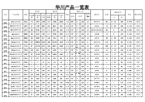
QD1115胶套
E660 96 3840 459 144 5760 689 2.2 175° 3′ 180 13
10-29
QD1117橡胶垫 E660 86 3095 317 129 4642 476
3 175° 3′ 180 13
10-43
JFZ191密封垫 T520 107 25600 3282 160 38400 4923 1.6 175° 3′ 180 0
E790
152
1364 187
227
2046
280
3.6 175° 2′ 120 13
10-11
9
8036
“□”67.8×63.5 ×2.3
E790
220
1979 271
330
2968
406
3.6 175° 2′ 120 13
10-10
9
8037 5×2
O形圈 F751 192 12288 525 288 18432 788 0.21 190° 2′ 120 13
大模具 小模具 小模具 小模具 小模具 大模具 小模具 小模具 大模具 小模具
单模 单模 小模具 小模具 小模具 小模具 小模具 小模具 小模具
8033
110J橡胶插头 G540 87 3142 255 131 4713 383 0.6 175° 3′7.8×64.5 ×2.3
1′30″ 90
1′30″ 90
2′30″ 150
2′10″ 130
2′40″ 160
4′
240
2′40″ 160
1′20″ 80
2′30″ 150
单价 模具类型
0.376 0.145 0.030 0.120 0.103 0.128 0.197 0.402 0.145 0.402 0.179 0.179 0.299 0.094 0.171 0.137 0.137 0.179 0.855
5082-2800中文资料

Schottky Barrier Diodes for General Purpose ApplicationsTechnical DataFeatures• Low Turn-On VoltageAs Low as 0.34 V at 1 mA• Pico Second Switching Speed • High Breakdown VoltageUp to 70 V• Matched Characteristics AvailableDescription/Applications The 1N5711, 1N5712, 5082-2800/ 10/11 are passivated Schottky barrier diodes which use a patented “guard ring” design to achieve a high breakdown voltage. Packaged in a low cost glass package, they are well suited for high level detecting, mixing, switching, gating, log or A-D converting, video detecting, frequency discriminating, sampling, and wave shaping.The 5082-2835 is a passivatedSchottky diode in a low cost glasspackage. It is optimized for lowturn-on voltage. The 5082-2835 isparticularly well suited for theUHF mixing needs of the CATVmarketplace.The 5082-2300 Series and5082-2900 devices are unpas-sivated Schottky diodes in a glasspackage. These diodes haveextremely low 1/f noise and areideal for low noise mixing, andhigh sensitivity detecting. Theyare particularly well suited for usein Doppler or narrow band videoreceivers.1N57111N57125082-2300 Series5082-2800 Series5082-2900DIMENSIONS IN MILLIMETERS AND (INCHES).Outline 15Maximum RatingsJunction Operating and Storage Temperature Range5082-2303, -2900.................................................................-60°C to +100°C 1N5711, 1N5712, 5082-2800/10/11....................................-65°C to +200°C 5082-2835............................................................................-60°C to +150°C DC Power Dissipation(Measured in an infinite heat sink at T CASE = 25°C)Derate linearly to zero at maximum rated temperature5082-2303, -2900..............................................................................100 mW 1N5711, 1N5712, 5082-2800/10/11.................................................250 mW 5082-2835.........................................................................................150 mW Peak Inverse Voltage.................................................................................V BRPackage CharacteristicsOutline 15Lead Material........................................................................................DumetLead Finish..............................................................................95-5% Tin-LeadMax. Soldering Temperature................................................260°C for 5 secMin. Lead Strength....................................................................4 pounds pullTypical Package Inductance1N5711, 1N5712:................................................................................2.0 nH2800 Series:........................................................................................2.0 nH2300 Series, 2900:..............................................................................3.0 nHTypical Package Capacitance1N5711, 1N5712:................................................................................0.2 pF2800 Series:........................................................................................0.2 pF2300 Series, 2900:............................................................................0.07 pFThe leads on the Outline 15 package should be restricted so that thebend starts at least 1/16 inch from the glass body.Outline 15 diodes are available on tape and reel. The tape and reelspecification is patterned after RS-296-D.Electrical Specifications at T= 25°CAGeneral Purpose DiodesMin.Max.V F = 1 V Max.Max.Max.Breakdown Forward at Forward Reverse Leakage Capaci-Part Package Voltage Voltage Current Current tance Number Outline V BR (V)V F (mV)I F (mA)I R (nA) at V R (V)C T (pF) 5082-280015704101520050 2.0 1N571115704101520050 2.0 5082-281015204103510015 1.2 1N571215205503515016 1.2 5082-28111515410201008 1.2 5082-2835158*34010*1001 1.0 Test I R = 10 µA I F = 1 mA*V F = 0.45 V V R = 0 V Conditions*I R = 100 µA f =1.0 MHz Note: Effective Carrier Lifetime (τ) for all these diodes is 100 ps maximum measured with Krakauer method at 5 mA except for 5082-2835 which is measured at 20 mA.Low 1/f (Flicker) Noise DiodesMin.Max.V F = 1 V Max.Max.Max.Part Breakdown Forward at Forward Reverse Leakage Capaci-Number Package Voltage Voltage Current Current tance 5082-Outline V BR (V)V F (mV)I F (mA)I R (nA) at V R (V)C T (pF) 230315204003550015 1.0 29001510400201005 1.2 Test I R = 10 µA I F = 1 mA V R = 0 V Conditions f =1.0 MHzNote: Effective Carrier Lifetime (τ) for all these diodes is 100 ps maximum measured with Krakauer method at 20 mA.Matched Pairs and QuadsBasic Matched MatchedPart Number Pair Quad Batch5082-Unconnected Unconnected Matched[1]Test Conditions2900∆VF at IF= 1.0, 10 mA28005082-28045082-2805∆V F at I F = 0.5, 5 mA ∆V F = 20 mV∆V F = 20 mV*I F = 10 mA∆C O at f = 1.0 MHz28115082-2826∆VF at IF= 10 mA∆V F = 10 mV∆C O at f = 1.0 MHz ∆C O = 0.1 pF28355082-2080∆VF at IF=10 mA∆V F = 10 mV∆C O at f = 1.0 MHz∆C O = 0.1 pFNote:1. Batch matched devices have a minimum batch size of 50 devices.SPICE ParametersParameter Units5082-28005082-28105082-28115082-28355082-23035082-2900B V V75251892510C J0pF 1.60.8 1.00.70.7 1.1E G eV0.690.690.690.690.690.69I BV A10E-510E-510E-510E-510E-510E-5I S A 2.2 x 10E-9 1.1 x 10E-90.3 x 10E-8 2.2 x 10E-87 x 1.0E-910E-8N 1.08 1.08 1.08 1.08 1.08 1.08 R SΩ25101051015 P B V0.60.60.60.560.640.64 PT222222 M0.50.50.50.50.50.5Typical ParametersV F – FORWARD VOLTAGE (V)Figure 1. I-V Curve Showing Typical Temperature Variation for 5082-2300 Series and 5082-2900 Schottky Diodes.1001010.10.01I F - F O R W A R D C U R R E N T (m A )V BR (V)Figure 2. 5082-2300 Series Typical Reverse Current vs. Reverse Voltage at Various Temperatures.10.0001,000100101I R (n A )051015100755025T A = 25°CI F - FORWARD CURRENT (mA)Figure 3. 5082-2300 Series and 5082-2900 Typical Dynamic Resistance (R D ) vs. Forward Current (I F ).100010010R D - D Y N A M I C R E S I S T AN C E (Ω)0.01010100V R - REVERSE VOLTAGE (V)Figure 4. 5082-2300 and 5082-2900 Typical Capacitance vs. Reverse Voltage.1.21.00.80.60.40.20C T - C A P A C I T A N C E (p F )048121620V F - FORWARD VOLTAGE (V)Figure 5. I-V Curve Showing Typical Temperature Variation for 5082-2800 or 1N5711 Schottky Diodes.5010510.50.10.050.01I F - F O R W A R D C U R R E N T (m A )00.20.40.60.8 1.0 1.2V R - REVERSE VOLTAGE (V)Figure 6. (5082-2800 OR 1N5711) Typical Variation of Reverse Current (I R ) vs. Reverse Voltage (V R ) at Various Temperatures.100,00010,0001000100101I R - R E V E R S E C U R R E N T (n A )0.20.40.60.81.01.2V R - REVERSE VOLTAGE (V)Figure 7. (5082-2800 or 1N5711)Typical Capacitance (C T ) vs. Reverse Voltage (V R ).12.01.51.00.50C T - C A P A C I T A N C E (p F )010********V F - FORWARD VOLTAGE (V)Figure 8. I-V Curve Showing Typical Temperature Variation for the 5082-2810 or 1N5712 Schottky Diode.100101.00.10.01I F - F O R W A R D C U R R E N T (m A )V R - REVERSE VOLTAGE (V)Figure 9. (5082-2810 or IN5712)Typical Variation of Reverse Current (I R ) vs. Reverse Voltage (V R ) at Various Temperatures.10,0001000100101.0I R - R E V E R S E C U R R E N T (n A )Typical Parameters, continuedV F - FORWARD VOLTAGE (V)Figure 10. I-V Curve Showing Typical Temperature Variation for the 5082-2811 Schottky Diode.100101.00.10.01I F - F O R W A R D C U R R E N T (m A )0.40.20.60.81.01.2V R - REVERSE VOLTAGE (V)Figure 11. (5082-2811) Typical Variation of Reverse Current (I R ) vs. Reverse Voltage (V R ) at Various Temperatures.100,00010,0001000100101I R - R E V E R S E C U R R E N T (n A )0510********V F - FORWARD VOLTAGE (V)Figure 12. I-V Curve Showing Typical Temperature Variations for 5082-2835 Schottky Diode.100101.00.10.01I F - F O R W A R D C U R R E N T (m A )00.20.40.60.8 1.0 1.2V R - REVERSE VOLTAGE (V)Figure 13. (5082-2835) Typical Variation of Reverse Current (I R ) vs. Reverse Voltage (V R ) at Various Temperatures.100,00010,0001000100101I R - R E V E R S E C U R R E N T (n A )0123456V R - REVERSE VOLTAGE (V)Figure 14. Typical Capacitance (C T ) vs. Reverse Voltage (V R ).C T - C A P A C I T A N C E (p F )0246810I F - FORWARD CURRENT (mA)Figure 15. Typical Dynamic Resistance (R D ) vs. Forward Current (I F ).1000100101R D - D Y N A M I C R E S I S T A N C E (Ω)Diode Package Marking1N5xxx5082-xxxxwould be marked:1Nx xxxxx xxYWW YWWwhere xxxx are the last four digits of the 1Nxxxx or the 5082-xxxx partnumber. Y is the last digit of the calendar year. WW is the work week ofmanufacture.Examples of diodes manufactured during workweek45 of 1999:1N57125082-3080would be marked:1N53071280945945Data subject to change.Copyright © 1999 Agilent TechnologiesObsoletes 5968-4304E5968-7181E (11/99)。
实力专业用品-实力专业用品-实力专业用品说明书

7
DIN Adaptors
DIN Adaptor for RGS SSRs
Installation Instructions
Ordering Key
RGS1DIN
DIN rail adaptor module for mounting the RGS series on DIN rail.
Suffix H8 added to SSR part no. refers to factory mounted DIN clip. Conditions apply. Please ask your Sales representative for further details.
Ordering Key
Ordering Key
RGN - TERMRES
RGN-TERMRES termination resistor to be fitted on the last RG..N on the NRG bus chain. Packing qty. 4 pc.
Specifications are subject to change without notice (30.07.2019)
3-pin socket to mate with RM1E..V.. 4-pin socket to mate with RA2A..C 4-pin socket to mate with RA2A..C
5-pin socket to mate with RA..S 4-pin socket to mate with RKD2..C 2-pin socket to mate with RK2..C
Material Thermal resistance
GBJ808中文资料
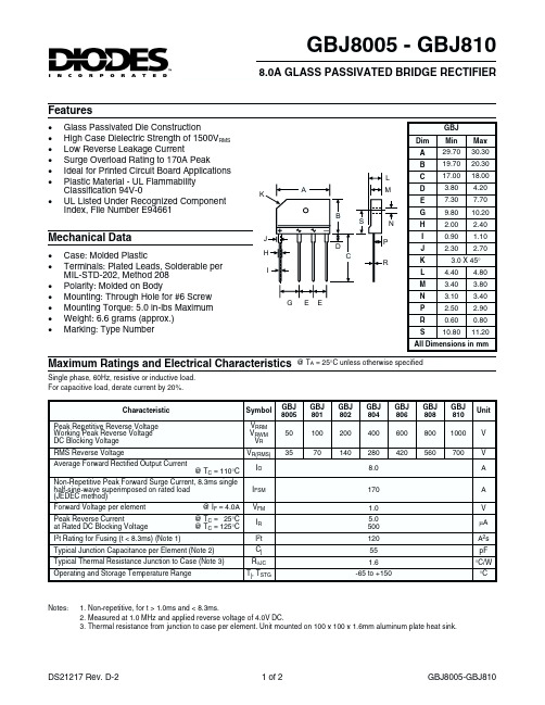
@ TA = 25°C unless otherwise specified
GBJ 8005 50 35
GBJ 801 100 70
GBJ 802 200 140
GBJ 804 400 280 8.0 170 1.0 5.0 500 120 55 1.6 -65 to +150
GBJ 806 600 420
L K A B M
C D E G
_
S P C R
N
H I J K L M N P R S
Mechanical Data
· · · · · · · Case: Molded Plastic Terminals: Plated Leads, Solderable per MIL-STD-202, Method 208 Polarity: Molded on Body Mounting: Through Hole for #6 Screw Mounting Torque: 5.0 in-lbs Maximum Weight: 6.6 grams (approx.) Marking: Type Number
GBJ Dim A B Min 29.70 19.70 17.00 3.80 7.30 9.80 2.00 0.90 2.30 4.40 3.40 3.10 2.50 0.60 10.80 Max 30.30 20.30 18.00 4.20 7.70 10.20 2.40 1.10 2.70 4.80 3.80 3.40 2.90 0.80 11.20
100
Tj = 25°C f = 1MHz
10
80
40
0
1
1 10 100
1
10 VR, REVERSE VOLTAGE (V) Fig. 4 Typical JuNUMBER OF CYCLES AT 60 Hz Fig. 3 Maximum Non-Repetitive Surge Current
塑料转子流量计选型手册

第 3 页/共 5 页
LZS-塑料管精密耐用转子流量计技术参数
型号
公称 通径
DN
测量范围
长管型
短管型
10-100l/h
精度
允许被测状况
温度℃
压力 MPA
尺寸
长管型
短管型
适用管道 (dg)
mm
16-160l/h
LZS-15 15
25-250l/h
L D1 D2 D3 L D1 D2
470 16 85 115 432 16 85
25
±4% 0-60 ≤0.6
0.4-4m3/h
LZS-40 40
0.6-6m3/h
570 18 110 150 500 18 110
40
1-10m3/h
0.4-4m3/h
LZS-50 50
0.6-6m3/h 1-10m3/h
570 18 125 165 520 18 125
50
1.6-16m3/h
2.5-16m3/h
LZS-65 65
5-25m3/h 8-40m3/h
530 18 130
65
12-60m3/h
LZS-80 65
2.5-16m3/h
540 18 160
80
第 4 页/共 5 页
5-25m3/h
8-40m3/h
12-60m3/h
LZS-
14-90m3/h
LZS-
150
18-150m3/h 20-150m3/h
150
20-180m3/h 25-180m3/h
20-200m3/h
550 18 180 215 510 18 180
上海欧际 液压软管 样本

公司全系列生产符合 ISO、DIN、JIS 标准的管路附件。符合 GB、GB/T、JB/ZQ、 JB、JB/T 等国家或行业标准的系列管路附件,旋转接头、快换接头、不锈钢金属 软管总成、液压胶管总成、铠装液压胶管总成、干稀油润滑设备。设计生产各种 非标的管路附件、液压系统等。
如:25-200(16M3K)-2000 B1+N-R1=B3+N-φ30*3 0° K1 S 7、当对胶管接头的型式没有严格要求时,用户可只提供外接口尺寸订货,
如:25-200-2000 N-R1= N-φ30*3 以上型号表示一端为外螺纹 R1,另一端为φ30*3 与钢管焊接。 我方将首选 24°锥 O 形圈密封胶管接头提供给用户。 8、为了代号的统一性,本样本中胶管接头的代号延用了灰色样本中的代号。 9、过渡接头的代号(如 N-R、N-G 等)在样本中重复使用,它不具体代表哪一类过渡接头,而 表示外接口的形式:
12 8 160 180 275 180 425 230
165 178 280 178
350 178 420 178 210 89 280 89
16 10 130 200 250 200 400 250 450 250 135 203 255 203
280 102 350 203 420 203 210 102 280 102
2
有限公司,中国二重集团(德阳)重型装备有限责任公司,大连重工集团有限公 司,大连华锐股份有限公司,上海重型机器厂有限公司,中华沪船新事业发展有 限公司,沈阳重型机器有限责任公司,陕西液压设备厂,宝钢集团常州冶金机械 厂、苏州冶金机械厂,衡冶重型机械有限公司,西安冶金机械有限公司,太原矿 山机械集团有限公司,济南重工股份有限公司等全国大型主机厂。公司产品出厂 合格率为 99.8%已在全国 19 个省市(自治区)66 个大型冶金及主机企业中占有一 席之地,抽样调查客户满意率为 99%,赢得了冶金企业,主机行业的国内外专家 及监制商的认可和好评。
派克液压中文样本

液压注意 – 用户方责任 错误或不当地选择或使用本样本或有关资料阐述的产品,可能会导致人生伤亡及财产损失! 本样本以及其它由派克汉尼汾公司及其子公司、销售公司与授权分销商所提供的资料,仅供用户专业技术人员在对产品和系统的选型进行深入调查考证时参考。
用户应全面分析自身设备的运行工况、适用的工业标准,并仔细查阅现行的样本,以详细地了解产品及系统的相关信息,通过自己的分析和试验,对产品及系统的独立的最终选择负责,确保能满足自身设备的所有性能、耐用性、维修型、安全性以及预警功能等要求。
对于派克或其子公司或授权分销商而言,应负责按用户提供的技术资料和规范,选择和提供适当的元件或系统,而用户则应负责确定这些技术资料和规范对其设备的所有运行工况和能合理预见的使用工况是否充分和准确。
目录目录页次概述 1 订货代号 2 技术参数 4 变量控制器 5 控制选项 “C”, 压力限定(恒压)变量控制器 5 控制选项 “L”, 负载传感及压力限定变量控制器 6 控制选项 “AM”, 带遥控口的标准型先导式压力限定变量控制器 7 控制选项 “AN”, 带ISO 4401 NG06先导阀安装界面的先导式压力限定变量控制器 8 控制选项 “AE”及“AF”, 带电磁比例调节的先导式压力限定变量控制器 9 控制选项 “AMT”, “ALT”及“LOT”, 带最高压力限定的扭矩限定(恒功率)变量控制器 10 P1性能特性 11典型流量特性 11 典型总效率特性 13 典型轴输入功率特性 15 典型噪声特性 18 典型轴承寿命 20 PD性能特性 22典型流量特性 22 典型总效率特性 24 典型轴输入功率特性 26 典型噪声特性 29 典型轴承寿命 31 安装尺寸 33 P1/PD 018 33 P1/PD 028 36 P1/PD 045 40 P1/PD 060 44 P1/PD 075 49 P1/PD 100 54 P1/PD 140 59 变量控制器安装尺寸 65 可提供的扩展的液压产品 75派克汉尼汾备记派克汉尼汾概述简介, 优点派克汉尼汾简介 • 开式回路用轴向柱塞式变量液压泵 • 中压,连续工作压力280 bar • 高驱动转速型,适用于行走机械; 低噪声型,适用于工业应用 • 静音及高效的控制效能 优点 • 总结构尺寸紧凑 • 低噪声• 流量脉动小,进一步降低噪声• 采用弹性密封,不使用密封垫,从而避免外泄漏的产生• 总效率高,功耗小,减小发热• 采用带无泄漏调节装的简单变量控制器 • 符合SAE 及ISO 标准的安装法兰及油口 • 采用圆锥滚柱轴承,使用寿命长 • 全功率后驱动能力• 后部或侧面油口配置可选• 泄油口的配置对水平安装及驱动轴向上垂直安装均适用• 带有最大及最小排量调节选项 • 具有壳体至吸口单向阀选项,可延长轴封寿命 • 使用、维修方便 脉动容腔技术下列图表所示为侧向油口配置P1/PD 18, 28及45泵采用 “脉动容腔” 技术的效果,脉动容腔可降低泵出口处的压力脉动幅值40-60%,这样,无需增加成本来加装噪声缓冲元件,便可大大降低液压系统的整体噪声,P1系列 PD 系列出口压力p / bar平均压力脉动 / b a rP1 045出口压力脉动2600 rpm 无脉动容腔2600 rpm 带脉动容腔订货代号18 ml, 28 ml, 45ml派克汉尼汾P 类型 01 驱动轴 转向R 5密封材料E 油口配置0 壳体-吸口 单向阀 0 排量调节 018 排量 S 安装法兰 及油口 S 轴封 M 应用范围A 设计系列0 通轴驱动选项 C0控制选项0附加控制选项 00油漆 00修改代号系列 P D * 仅适用于045排量, “S”型安装法兰及油口00 标准型, 无修改M2 按要求修改 代号修改代号 * 适用于028及045排量 ** 仅适用于045排量 代号设计系列 A 现行设计系列5 氟碳橡胶 (FPM) 代号密封材料 A 82-2 SAE A M33x2 M27x2 BSPP 1/4”, 3/8” 101-2 SAE B M42x2 M27x2 BSPP 1/4”, 1/2” 101-2SAE B M48x2M33x2Ø38/25DN51/25BSPP 1/4”, 1/2”B ISO M33x2 M27x2 BSPP 1/4”,3/8”ISO M42x2 M27x2 BSPP 1/4”, 1/2” ISO M48x2M33x2Ø38/25DN51/25BSPP 1/4”, 1/2”代号 018排量 028排量 045排量 安装法兰及油口 安装 法兰 螺纹 油口 辅助 油口 安装 法兰 螺纹 油口 辅助 油口 安装法兰螺纹油口法兰 油口辅助 油口 S 82-2 SAE A SAE 16/12 SAE 4/6 101-2 SAE B SAE 20/12 SAE 4/8 101-2SAE B SAE 24/16Ø38/2561系列SAE 4/10M ISO M33x2 M27x2 M12x1.5 M16x1.5 ISO M42x2 M27x2 M12x1.5 M22x1.5 ISO M48x2M33x2Ø38/25DN51/25M12x1.5M22x1.5代号 018驱动轴 028驱动轴 045驱动轴 01 SAE A 11T 花键SAE B-B 15T 花键 SAE B-B 15T 花键02 SAE 19-1平键Ø0.75” SAE B-B 平键Ø1” SAE B-B 平键Ø1” 08— SAE B 13T 花键 SAE B 13T 花键 04 ISO/DIN 平键, Ø20ISO/DIN 平键, Ø25ISO/DIN 平键, Ø25 06 SAE A 9T 花键— — PD 工业液压用 代号 系列P1 行走机械用 代号 排量 018 18 ml/rev (1.10 in 3/rev) 028 28 ml/rev (1.71 in 3/rev) 045 45 ml/rev (2.75 in 3/rev) 代号 类型 P 开式回路用变量柱塞泵 U*通用 代号应用范围 S 工业液压 (PD) M 行走机械 (P1) R 顺时针 (右转)L 逆时针 (左转)代号 转向 代号 轴封 S 单唇轴封 * 并不具有控制功能,仅在运输时予以防护,详情见第7页的控制说明。
JP系列低压综合配电箱说明书

JP系列低压综合配电箱安装使用说明书1、概述JP系列10kV变压器综合配电箱(以下简称“配电箱”),适用于广大农村配电变压器额定频率交流50Hz,额定工作电压400V,额定电流800A及以下的配电系统中,户外柱上安装使用。
配电箱具备远程在线监测、电能分配、电能计量、无功补偿和剩余电流保护等功能的综合低压成套开关设备与控制设备。
2、型号及含义JP —□/ □补偿容量(kvar)变压器容量(kVA)低压综合配电箱3、执行标准GB 4208 外壳防护等级(IP代码)GB/Z 6829 剩余电流动作保护电器的一般要求GB 7251.12 低压成套开关设备和控制设备第2部分:低压成套开关设备和控制设备第2部分:成套电力开关和控制设备GB/T 10233 低压成套开关设备和电控设备基本试验方法GB 13955 剩余电流动作保护装置安装和运行GB 14048.2 低压开关设备和控制设备第2部分:断路器GB/T 15576 低压成套无功功率补偿装置GB/T 17626.2 电磁兼容试验和测量技术静电放电抗扰度试验GB/T 17626.3 电磁兼容试验和测量技术射频电磁场辐射抗扰度试验GB/T 17626.4 电磁兼容试验和测量技术电快速瞬变脉冲群抗扰度试验GB/T 17626.5 电磁兼容试验和测量技术浪涌(冲击)抗扰度试验DL/T 375 户外配电箱通用技术条件DL/T 499 农村低压电力技术规程DL/T 614 多功能电能表DL/T 620 交流电气装置的过电压保护和绝缘配合4、使用环境条件配电箱的使用环境条件,见表1。
表1 使用环境条件5、主要技术参数配电箱的主要技术参数,见表2、表3。
表3 400kVA配变用,1进3出,有补偿配电箱主要技术参数6、装置功能单元的划分和要求6.1 装置划分为以下单元:a)计量/测量表计单元;b)控制保护单元;c)无功补偿单元。
5.2.1 计量/测量表计单元计量装置设单独计量室单元,集中布置,密封隔离,单独设门,并设观察窗。
5082-A808-MO000中文资料

Features• Low Power Consumption • Industry Standard Size• Industry Standard Pinout • Choice of Character Size7.6 mm (0.30 in), 10 mm (0.40 in), 10.9 mm (0.43 in), 14.2 mm (0.56 in), 20 mm (0.80 in)• Choice of ColorsAlGaAs Red, High Efficiency Red (HER), Yellow, Green• Excellent Appearance Evenly Lighted Segments±50° Viewing Angle• Design FlexibilityCommon Anode or Common CathodeSingle and Dual DigitLeft and Right Hand Decimal Points±1. Overflow Character• Categorized for Luminous IntensityYellow and Green Categorized for ColorUse of Like Categories Yields a Uniform Display• Excellent for Long Digit String Multiplexing DescriptionThese low current seven segment displays are designed for applica-tions requiring low power consumption. They are tested and selected for their excellent low current characteristics to ensure that the segments are matched at low currents. Drive currents as low as 1 mA per segment are available.Pin for pin equivalent displays are also available in a standard current or high light ambient design. The standard current displays are available in all colors and are ideal for most applica-tions. The high light ambient displays are ideal for sunlight ambients or long string lengths. For additional information see the 7.6 mm Micro Bright Seven Segment Displays, 10 mm Seven Segment Displays, 7.6 mm/10.9 mm Seven Segment Displays, 14.2 mm Seven Segment Displays, 20 mm Seven Segment Displays, or High Light Ambient Seven Segment Displays data sheets.Low Current Seven SegmentDisplays Technical Data HDSP-335x SeriesHDSP-555x SeriesHDSP-751x SeriesHDSP-A10x Series HDSP-A80x Series HDSP-A90x Series HDSP-E10x Series HDSP-F10x Series HDSP-G10x Series HDSP-H10x Series HDSP-K12x, K70x Series HDSP-N10x SeriesHDSP-N40x SeriesDevicesAlGaAs HER Yellow Green Package HDSP-HDSP-HDSP-HDSP-Description Drawing A1017511A801A9017.6 mm Common Anode Right Hand Decimal A A1037513A803A9037.6 mm Common Cathode Right Hand Decimal B A1077517A807A9077.6 mm Common Anode ±1. Overflow C A1087518A808A9087.6 mm Common Cathode ±1. Overflow D F10110 mm Common Anode Right Hand Decimal E F10310 mm Common Cathode Right Hand Decimal F F10710 mm Common Anode ±1. Overflow G F10810 mm Common Cathode ±1. Overflow H G10110 mm Two Digit Common Anode Right Hand Decimal X G10310 mm Two Digit Common Cathode Right Hand Decimal Y E100335010.9 mm Common Anode Left Hand Decimal I E101335110.9 mm Common Anode Right Hand Decimal J E103335310.9 mm Common Cathode Right Hand Decimal K E106335610.9 mm Universal ±1. Overflow[1]L H101555114.2 mm Common Anode Right Hand Decimal M H103555314.2 mm Common Cathode Right Hand Decimal N H107555714.2 mm Common Anode ±1. Overflow O H108555814.2 mm Common Cathode ±1. Overflow P K121K70114.2 mm Two Digit Common Anode Right Hand Decimal R K123K70314.2 mm Two Digit Common Cathode Right Hand Decimal S N10020 mm Common Anode Left Hand Decimal Q N101N40120 mm Common Anode Right Hand Decimal T N103N40320 mm Common Cathode Right Hand Decimal U N10520 mm Common Cathode Left Hand Decimal V N106N40620 mm Universal ±1. Overflow[1]W Note:1. Universal pinout brings the anode and cathode of each segment’s LED out to separate pins. See internal diagrams L or W.Part Numbering System5082-x xx x-x x x xxHDSP-x xx x-x x x xxMechanical Options[1]00: No mechanical optionColor Bin Options[1,2]0: No color bin limitationMaximum Intensity Bin[1,2]0: No maximum intensity bin limitationMinimum Intensity Bin[1,2]0: No minimum intensity bin limitationDevice Configuration/Color[1]G: GreenDevice Specific Configuration[1]Refer to respective datasheetPackage[1]Refer to Respective datasheetNotes:1. For codes not listed in the figure above, please refer to the respective datasheet or contact your nearest Agilent representative fordetails.2. Bin options refer to shippable bins for a part-number. Color and Intensity Bins are typically restricted to 1 bin per tube (excep-tions may apply). Please refer to respective datasheet for specific bin limit information.Package DimensionsPackage Dimensions (cont.)Package Dimensions (cont.)*The Side View of package indicates Country of Origin.Package Dimensions (cont.)Package Dimensions (cont.)Package Dimensions (cont.)Internal Circuit DiagramInternal Circuit Diagram (cont.)Absolute Maximum RatingsAlGaAs Red - HDSP-HERA10X/E10X/H10X HDSP-751X/Yellow GreenK12X/N10X/N40X335X/555X/HDSP-A80X HDSP-A90X Description F10X, G10X Series K70X Series Series Series Units Average Power per Segment or DP375264mW Peak Forward Current per 45mA Segment or DPDC Forward Current per15[1]15[2]mA Segment or DPOperating Temperature Range-20 to +100-40 to +100°C Storage Temperature Range -55 to +100°C Reverse Voltage per Segment 3.0V or DPWave Soldering Temperature for 3Seconds (1.60 mm [0.063 in.] below 250°C seating body)Notes:1. Derate above 91°C at 0.53 mA/°C.2. Derate HER/Yellow above 80°C at 0.38 mA/°C and Green above 71°C at 0.31 mA/°C.Electrical/Optical Characteristics at T A = 25°CAlGaAs RedDeviceSeriesHDSP-Parameter Symbol Min.Typ.Max.Units Test Conditions315600I F = 1 mA A10x3600I F = 5 mA330650I F = 1 mAF10x, G10x3900I F = 5 mA390650I F = 1 mA E10x Luminous Intensity/Segment[1,2]I Vµcd(Digit Average)3900I F = 5 mA400700I F = 1 mAH10x, K12x4200I F = 5 mA270590I F = 1 mAN10x, N40x3500I F = 5 mA1.6I F = 1 mAForward Voltage/Segment or DP V F 1.7V I F = 5 mA1.82.2I F = 20 mA PkAll Devices Peak WavelengthλPEAK645nmDominant Wavelength[3]λd637nmReverse Voltage/Segment or DP[4]V R 3.015V I R = 100 µATemperature Coefficient of∆V F/°C-2 mV mV/°CV F/Segment or DPA10x255F10x, G10x320E10x340Thermal Resistance LED RθJ-PIN°C/W/SegH10x, K12x Junction-to-Pin400N10x, N40x430High Efficiency RedDeviceSeriesHDSP-Parameter Symbol Min.Typ.Max.Units Test Conditions160270I F = 2 mA 751x1050I F = 5 mA200300I F = 2 mA Luminous Intensity/Segment[1,2]I V mcd(Digit Average)1200I F = 5 mA335x, 555x,K70x270370I F = 2 mA1480I F = 5 mA1.6I F = 2 mAForward Voltage/Segment or DP V F 1.7V I F = 5 mA2.1 2.5I F = 20 mA Pk All Devices Peak WavelengthλPEAK635nmDominant Wavelength[3]λd626nmReverse Voltage/Segment or DP[4]V R 3.030V I R = 100 µATemperature Coefficient of∆V F/°C-2mV/°CV F/Segment or DP751x200335x Thermal Resistance LED RθJ-PIN280°C/WJunction-to-Pin555x, K70x345YellowDeviceSeriesHDSP-Parameter Symbol Min.Typ.Max.Units Test Conditions Luminous Intensity/Segment[1,2]250420I F = 4 mA(Digit Average)I V mcd1300I F = 10 mA1.7I F = 4 mAForward Voltage/Segment or DP V F 1.8V I F = 5 mA A80x2.1 2.5I F = 20 mA PkPeak WavelengthλPEAK583nmDominant Wavelength[3,5]λd581.5585592.5nmReverse Voltage/Segment or DP[4]V R 3.030V I R = 100 µATemperature Coefficient of∆V F/°C-2mV/°CV F/Segment or DPThermal Resistance LED RθJ-PIN200°C/WJunction-to-PinGreenDeviceSeriesHDSP-Parameter Symbol Min.Typ.Max.Units Test Conditions Luminous Intensity/Segment[1,2]250475I F = 4 mA(Digit Average)I V mcd1500I F = 10 mA1.9I F = 4 mAForward Voltage/Segment or DP V F 2.0V I F = 10 mA A90x2.1 2.5I F = 20 mA PkPeak WavelengthλPEAK566nmDominant Wavelength[3,5]λd571577nmReverse Voltage/Segment or DP[4]V R 3.030V I R = 100 µATemperature Coefficient of∆V F/°C-2mV/°CV F/Segment or DPThermal Resistance LED RθJ-PIN200°C/WJunction-to-PinNotes:1. Device case temperature is 25°C prior to the intensity measurement.2. The digits are categorized for luminous intensity. The intensity category is designated by a letter on the side of the package.3. The dominant wavelength, λd, is derived from the CIE chromaticity diagram and is the single wavelength which defines the color of thedevice.4. Typical specification for reference only. Do not exceed absolute maximum ratings.5. The yellow (HDSP-A800) and Green (HDSP-A900) displays are categorized for dominant wavelength. The category is designated by anumber adjacent to the luminous intensity category letter.AlGaAs RedIntensity Bin Limits (mcd)AlGaAs RedHDSP-A10xIV Bin Category Min.Max.E0.3150.520F0.4280.759G0.621 1.16H0.945 1.71I 1.40 2.56J 2.10 3.84K 3.14 5.75L 4.708.55HDSP-E10x/F10x/G10xIV Bin Category Min.Max.D0.3910.650E0.5320.923F0.755 1.39G 1.13 2.08H 1.70 3.14HDSP-H10x/K12xIV Bin Category Min.Max.C0.4150.690D0.5650.990E0.810 1.50F 1.20 2.20G 1.80 3.30H 2.73 5.00I 4.097.50HDSP-N10xIV Bin Category Min.Max.A0.2700.400B0.3250.500C0.4150.690D0.5650.990E0.810 1.50F 1.20 2.20G 1.80 3.30H 2.73 5.00I 4.097.50Intensity Bin Limits (mcd), continued HERHDSP-751xIV Bin Category Min.Max.B0.1600.240C0.2000.300D0.2500.385E0.3150.520F0.4280.759G0.621 1.16HDSP-751xIV Bin Category Min.Max.B0.2400.366C0.3000.477D0.3910.650E0.5320.923F0.755 1.39G 1.13 2.08H 1.70 3.14HDSP-555x/K70xIV Bin Category Min.Max.A0.2700.400B0.3250.500C0.4150.690D0.5650.990E0.810 1.50F 1.20 2.20G 1.80 3.30H 2.73 5.00I 4.097.50Intensity Bin Limits (mcd), continued YellowHDSP-A80xIV Bin Category Min.Max.D0.2500.385E0.3150.520F0.4250.760G0.625 1.14H0.940 1.70I 1.40 2.56J 2.10 3.84K 3.14 5.76L 4.718.64M7.0713.00N10.6019.40O15.9029.20P23.9043.80Q35.8065.60GreenHDSP-A90xIV Bin Category Min.Max.E0.3150.520F0.4250.760G0.625 1.14H0.940 1.70I 1.40 2.56J 2.10 3.84K 3.14 5.76L 4.718.64M7.0713.00N10.6019.40O15.9029.20P23.9043.80Q35.8065.60Electrical/OpticalFor more information on electrical/optical characteristics, please see Application Note 1005.Contrast Enhancement For information on contrast enhancement, please see Application Note 1015.Soldering/Cleaning Cleaning agents from the ketone family (acetone, methyl ethyl ketone, etc.) and from the chorinated hydrocarbon family (methylene chloride, trichloro-ethylene, carbon tetrachloride, etc.) are not recommended for cleaning LED parts. All of these various solvents attack or dissolve the encapsulating epoxies used to form the package of plastic LED parts.For information on soldering LEDs, please refer to Application Note 1027.Note:All categories are established for classification of products. Productsmay not be available in all categories. Please contact your localAgilent representatives for further clarification/information.Color Categories/semiconductorsFor product information and a complete list ofdistributors, please go to our web site.For technical assistance call:Americas/Canada: +1 (800) 235-0312 or(916) 788 6763Europe: +49 (0) 6441 92460China: 10800 650 0017Hong Kong: (+65) 6271 2451India, Australia, New Zealand: (+65) 6271 2394Japan: (+81 3) 3335-8152(Domestic/International), or0120-61-1280(Domestic Only)Korea: (+65) 6271 2194Malaysia, Singapore: (+65) 6271 2054Taiwan: (+65) 6271 2654Data subject to change.Copyright © 2005 Agilent Technologies, Inc.Obsoletes 5988-8412ENJanuary 19, 20055989-0080EN。
水龙头cn
04-001-32-13
内摩擦片Ⅲ
2
SL001.32.13
23
04-001-32-14
内联结套
1
SL001.32.14
24
04-001-32-15
加力套
1
SL001.32.15
25
B8931-075-59
挡圈75
1
26
6009
轴承45×75×16
1
GB/T276-94
27
04-001-32-16
1
46
04-001-45
活接头Rc1 1/2"
1
47
04-001-28-00
管1 1/2"
1
SL001.28.00
48
B08
螺母M24×
1
GB812-88
49
04-001-29
接头
1
50
04-001-30-00
联结管(一)
1
SL001.30.00
51
04-001-31-00
联结管(二)
1
SL001.31.00
11
B1152-10-01
油杯M10×1
1
GB1152-89
12
04-001-05-10
下盘根盒
1
SL001.05.10
13
04-001-05-11
隔环
2
SL001.05.11
14
04-001-05-12
下O型密封压套
1
SL001.05.12
15
B3452
O型密封圈109×
1
GB/
16
B0075-10-012-74
深圳市富满电子集团股份有限公司 5088SS二合一锂电池保护IC说明书
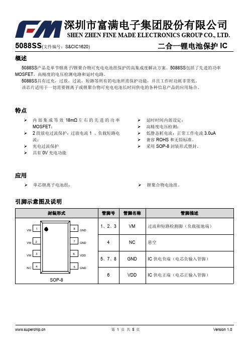
5088SS(文件编号:S&CIC1620)二合一锂电池保护IC概述5088SS产品是单节锂离子/锂聚合物可充电电池组保护的高集成度解决方案。
5088SS包括了先进的功率MOSFET,高精度的电压检测电路和延时电路。
5088SS具有过充,过放,过流,短路等所有的电池所需保护功能,并且工作时功耗非常低。
该芯片适用于一切需要锂离子或锂聚合物可充电电池长时间供电的各种信息产品的应用场合。
特点内部集成等效18mΩ左右的先进的功率MOSFET;2段放电过流保护:过放电流1、负载短路电流;充电过流保护具有0V充电功能延时时间内部设定;高精度电压检测;低静态耗电流:正常工作电流3.0uA兼容ROHS和无铅标准。
采用SOP-8封装形式塑封。
应用单芯锂离子电池组; 锂聚合物电池组。
5088SS(文件编号:S&CIC1620)二合一锂电池保护IC 极限参数电气特性参数5088SS(文件编号:S&CIC1620)二合一锂电池保护IC 功能描述5088SS是一款高精度的锂电池保护电路。
正常状态下,如果对电池进行充电,则5088SS可能会进入过电压充电保护状态;同时,满足一定条件后,又会恢复到正常状态。
如果对电池放电,则可能会进入过电压放电保护状态或过电流放电保护状态;同时,满足一定条件后,也会恢复到正常状态。
正常状态在正常状态下,5088SS由电池供电,其VDD端电压在过电压充电保护阈值V OC和过电压放电保护阈值V OD 之间,VM端电压在充电器检测电压(V CHG)与过电流放电保护阈值(V EDI)之间,内置N-MOS管导通。
此时,既可以使用充电器对电池充电,也可以通过负载使电池放电。
过电压充电保护状态保护条件正常状态下,对电池进行充电,如果使VDD端电压升高超过过电压充电保护阈值V OC,且持续时间超过过电压充电保护延迟时间t OC,则5088SS将使内置N-MOS管关闭,充电回路被“切断”,即5088SS进入过电压充电保护状态。
Schedule 80 PVC 产品及配件说明说明书

Pk Ctn Code Each TeeSoc801-0021/4503000809.32 801-0033/8251500809.32 801-0051/2252000809.32 801-0073/4151200809.77 801-010*********.22 801-0121-1/410008033.57 801-0151-1/210008033.57 801-020*********.97 801-0252-1/210008045.64 801-03035008057.04 801-04045008066.09 801-050550080161.21 801-050F514083376.81 801-060620080225.66 801-080820080523.37 801-080F810083493.67 801-10010100811729.11 801-100F1010083877.32 801-12012100812441.99 801-120F12100831236.18 801-140F14100832593.45 801-160F16100833372.26 801-180F181********.12 801-200F20100835179.05 801-240F24100836883.12 TeeSoc x Fipt802-0021/42515008021.55 802-0051/22016008014.74 802-0073/42016008019.07 802-010*********.32 802-0121-1/415008023.85 802-0151-1/210008028.03 802-020*********.57 802-03035008073.78 802-040450080138.62 Special Reinforced TeeSoc x SR Fipt - Stainless Steel Collar802-005SR1/2252000868.06 802-007SR3/41512008611.40 802-010SR115008613.39 802-012SR1-1/425008615.93 802-020SR210008632.93 802-030SR35008671.16 802-040SR450086133.45 Transition TeeSoc x Fipt With Brass Thread Insert802-005BR1/22016008632.92 802-007BR3/4208008665.97 Not intended to convey or dispense water for human consumption through drinking or cookingTeeFipt805-0021/42515008010.77 805-0033/82515008010.77Pk Ctn Code Each Tee (continued)Fipt805-0051/22024008010.77 805-0073/41512008011.99 805-010*********.47 805-0121-1/410008028.06 805-0151-1/210008034.02 805-020*********.57 805-0252-1/250080133.15 805-030350080139.06 805-040450080226.00 805-060F612083355.13 805-080F810083655.33 Special Reinforced TeeSR Fipt -Stainless Steel Collar805-002SR1/4251500869.38 805-003SR3/8251500869.38 805-005SR1/2251500869.68 805-007SR3/42510008610.64 805-010SR115008625.29 805-015SR1-1/210008629.60 805-020SR210008631.12 Street TeeSpig x Soc x Soc844-0051/22520008011.65 844-0073/41512008012.22 844-010*********.27 844-0121-1/410008041.97 844-0151-1/210008041.97 844-020*********.45 Reducing TeeSoc801-1013/4X1/2151200807.14 801-1301X1/215008010.33 801-1311X3/415008010.33 801-1571-1/4X1X3/415008017.04 801-1581-1/4X1X115008017.04 801-1591-1/4X1X1-1/415008017.04 801-16611-1/4X1/210008028.48 801-1671-1/4X3/410008022.41 801-1681-1/4X115008022.41 801-2021-1/2X1-1/4X110008022.41 801-2091-1/2X1/210008022.41 801-2101-1/2X3/415008022.41 801-2111-1/2X110008022.41 801-2121-1/2X1-1/410008022.41 801-2472X1/210008028.40 801-2482X3/410008028.40 801-2492X110008028.40 801-25012X1-1/410008043.29 801-2512X1-1/210008028.40 801-2872-1/2X1/210008043.41 801-2882-1/2X3/410008043.41 801-2892-1/2X110008037.05 801-2902-1/2X1-1/410008037.05 801-2912-1/2X1-1/210008037.05 801-2922-1/2X210008037.05 801-33313X1/25008052.05 801-33413X3/45008058.74 801-3353X15008052.05 801-33613X1-1/45008052.05Pk Ctn Code Each Reducing Tee (continued)Soc801-3373X1-1/25008052.05 801-3383X25008052.05 801-3393X2-1/26008052.05 801-41614X3/450080102.95 801-41714X150080102.95 801-41814X1-1/450080102.95 801-4194X1-1/25008084.11 801-4204X25008084.11 801-42114X2-1/250080151.42 801-4224X35008084.11 801-42614X640080412.22 801-482F5X1-1/415083222.99 801-484F5X1-1/215083227.20 801-486F5X215083227.20 801-487F5X2-1/214083259.08 801-488F5X313083267.56 801-49015X440080250.94 801-490F5X414083285.62 801-52316X1/240080218.75 801-5256X140080168.07 801-52616X1-1/440080218.75 801-52716X1-1/240080218.75 801-5286X240080168.07 801-52916X2-1/240080218.57 801-5306X340080168.07 801-5326X450080225.66 801-533F6X513083475.01 801-537F6X10100831848.89 801-539F6X12100832052.88 801-57318X1/220080642.20 801-57518X120080642.59 801-57818X220080611.02 801-578F8X212083419.13 801-57918X2-1/220080672.29 801-579F8X2-1/212083423.02 801-58018X320080611.02 801-580F8X312083427.76 801-58218X420080611.02 801-582F8X412083449.80 801-583F8X510083608.07 801-5858X620080523.37 801-59118X12100813733.67 801-621F10X212083629.60 801-622F10X2-1/210083657.58 801-623110X3100811611.03 801-623F10X310083675.24 801-624110X4100811611.03 801-624F10X410083699.53 801-625F10X510083752.27 801-626110X6100811521.63 801-626F10X610083791.13 801-628110X8100811790.76 801-628F10X810083887.53 801-632F10X12100832186.24 801-661F12X210083814.14 801-662F12X2-1/210083849.28 801-663F12X310083876.99 801-664112X4100812920.84 801-664F12X410083930.33 801-665F12X510083974.92 801-666112X6100812755.74 801-666F12X6100831027.26 801-66812X8100812263.74 801-668F12X8100831102.11 801-670112X10100813031.45Pk Ctn Code Each Reducing Tee (continued)Soc801-670F12X10100831224.68 801-678F12X181********.97 801-691F14X2100831020.11 801-692F14X2-1/2100831071.69 801-693F14X3100831252.40 801-694F14X4100831380.16 801-696F14X6100831489.88 801-698F14X8100831566.69 801-700F14X10100831673.75 801-702F14X12100831767.38 801-706F14X16100835718.92 801-751F16X2100831308.13 801-752F16X2-1/2100831391.37 801-753F16X3100831411.31 801-754F16X4100831544.03 801-756F16X6100831642.60 801-758F16X8100831824.44 801-760F16X10100831977.71 801-762F16X12100832179.49 801-764F16X14100832513.14 801-781F18X2100831503.78 801-783F18X3100831830.92 801-784F18X4100832811.82 801-786F18X6100833045.48 801-788F18X8100833175.88 801-790F18X10100833402.34 801-792F18X12100833595.58 801-794F18X14100833821.21 801-796F18X16100833870.03 801-814F20X4100833448.54 801-816F20X6100833641.28 801-818F20X8100833753.20 801-820F20X10100833908.31 801-822F20X12100834190.71 801-824F20X14100834493.97 801-826F20X16100834816.71 801-828F20X181********.75 801-904F24X4100834293.87 801-906F24X6100834458.31 801-908F24X8100834574.25 801-910F24X10100834855.74 801-912F24X12100835034.93 801-914F24X14100835242.69 801-916F24X16100835484.55 801-918F24X181********.87 801-920F24X20100836759.89¹Sized with BushingReducing TeeSoc x Fipt802-1013/4X1/21512008013.54 802-1301X1/250008014.07 802-1311X3/415008018.08 802-1661-1/4X1/225008023.01 802-16711-1/4X3/415008023.01 802-1681-1/4X110008045.67 802-2091-1/2X1/225008028.48 802-21011-1/2X3/420008028.48 802-2111-1/2X110008028.48 802-2121-1/2X1-1/410008028.48 802-2472X1/210008032.54 802-2482X3/410008032.54 802-24912X110008043.29Pk Ctn Code Each Reducing Tee (continued)Soc x Fipt802-25012X1-1/410008043.29 802-25112X1-1/210008060.36 802-2872-1/2X1/210008074.92 802-28812-1/2X3/410008074.92 802-28912-1/2X110008074.92 802-29012-1/2X1-1/410008074.92 802-29112-1/2X1-1/210008074.92 802-29212-1/2X210008083.65 802-33313X1/25008058.74 802-33413X3/45008058.74 802-33513X15008070.65 802-33613X1-1/45008070.65 802-33713X1-1/25008070.65 802-33813X25008090.22 802-33913X2-1/250080126.89 802-41514X1/250080103.37 802-41614X3/450080103.37 802-41714X150080103.37 802-41814X1-1/450080103.37 802-41914X1-1/250080103.37 802-42014X250080154.52 802-42114X2-1/250080154.52 802-42214X350080172.98 802-52516X140080240.54 802-52616X1-1/440080240.54 802-52716X1-1/240080240.54 802-52816X240080240.54 802-528F*6X213083438.05 802-52916X2-1/240080240.54 802-53016X340080335.81 802-53216X420080351.83 802-532F*6X414083542.85 802-57818X220080655.62 802-578F8X212083586.67 802-58018X320080655.62 802-580F8X312083586.67 802-58218X420080655.62 802-582F*8X412083650.24 802-621110X2100811674.26 802-621F10X210083712.39 802-623110X3100801674.26 802-623F10X310083770.05 802-624110X4100811674.26 802-624F*10X410083855.49 802-661112X2100812652.85 802-661F12X210083904.88 802-663112X3100812652.85 802-663F12X310083981.88 802-664112X4100812652.85 802-664F12X4100831083.75¹Sized with Bushing* An asterisk (*) appearing after a fabricated fitting part number indicates the item is fiberglass reinforced.Reducing TeeSoc x Fipt x Soc803-0953/4X1/2X3/450008012.69Special Reinforced Reducing TeeSoc x SR Fipt -Stainless Steel Collar802-072SR1/2X1/4251500868.06 802-098SR3/4X1/42510008610.47Pk Ctn Code Each Special Reinforced Reducing Tee (continued)Soc x SR Fipt -Stainless Steel Collar802-101SR3/4X1/250008610.47 802-128SR11X1/4108008624.79 802-130SR1X1/250008612.92 802-131SR1X3/415008624.79 802-164SR11-1/4X1/45008626.43 802-166SR1-1/4X1/225008617.52 802-168SR1-1/4X110008617.87 802-207SR11-1/2X1/410008630.84 802-211SR1-1/2X110008619.35 802-212SR1-1/2X1-1/410008619.35 802-245SR12X1/410008635.62 802-247SR2X1/210008635.62 802-248SR2X3/410008635.62 802-287SR2-1/2X1/210008626.25 802-331SR13X1/45008668.00 802-333SR13X1/25008669.97 802-413SR14X1/45008693.64 802-415SR14X1/250086101.77¹Sized with BushingSpecial Reinforced Reducing TeeSoc x SR Fipt -Stainless Steel Collar x Soc(See also Gauge & Instrument Fittings for additional configurations)803-095SR3/4X1/2X3/415008613.19Transition Reducing TeeSoc x Fipt With Brass Thread Insert802-101BR3/4X1/250008641.08 Not intended to convey or dispense water for human consumption through drinking or cooking90° EllSoc806-0021/425150080 3.31 806-0033/820120080 3.31 806-0051/220240080 3.31 806-0073/420160080 4.22 806-010******* 6.80 806-0121-1/41000809.11 806-0151-1/21000809.76 806-020*********.79 806-0252-1/25008027.59 806-03035008031.01 806-04045008047.16 806-045F4-1/212083216.82 806-050540080120.91 806-050F514083242.08 806-060640080134.19 806-080820080369.86 806-10010100811655.26 806-100F1010083660.59 806-12012100812157.75 806-120F12100831079.76 806-140F14100831377.35 806-160F16100831712.98 806-180F181********.07 806-200F20100832923.53 806-240F24100834489.44 806-33813X25008076.01 806-42214X350080113.54¹Sized with BushingPk Ctn Code Each90° Ell SweepSoc x Soc806-005S1/2251500808.24 806-007S3/42510008010.67 806-010S125008017.19 806-012S1-1/425008022.73 806-015S1-1/225008024.43 806-020S225008029.60Long Sweep 90° EllSoc806-005LSF1/212508328.57 806-007LSF3/412508332.06 806-010LSF112508335.84 806-012LSF1-1/412508360.62 806-015LSF1-1/212508361.39 806-020LSF211008366.37 806-025LSF2-1/217083113.97 806-030LSF315083124.34 806-040LSF414083139.43 806-060LSF612083213.55 Not Listed for Electrical Conduit Use90° EllSoc x Fipt807-0021/42545008013.00 807-0033/82515008013.00 807-0051/22024008013.00 807-0073/42016008015.29 807-010*********.54 807-0121-1/410008019.07 807-0151-1/210008022.75 807-020*********.47 807-03035008070.39 807-040450080132.74 807-0601630080307.99¹Thread outlet sized with Female AdapterSpecial Reinforced 90° EllSoc x SR Fipt -Stainless Steel Collar807-005SR1/2202400867.72 807-007SR3/47500869.18 807-010SR15000869.28 807-012SR1-1/425008612.47 807-015SR1-1/210008615.41 807-020SR210008617.68 807-030SR35008644.89 807-040SR45008679.32Transition 90° EllSoc x Fipt With Brass Thread Insert807-005BR1/22024008628.92 807-007BR3/42016008651.19 Not intended to convey or dispense water for human consumption through drinking or cooking90° EllFipt808-0021/4254500808.20 808-0033/8251500808.20Pk Ctn Code Each 90° Ell (continued)Fipt808-0051/2201200807.65 808-0073/4202400809.53 808-01011512008011.99 808-0121-1/410008012.92 808-0151-1/210008018.32 808-020*********.64 808-0252-1/25008080.37 808-030350080129.60 808-040450080228.04 90° Street EllMipt x Fipt812-0021/45030008017.63 812-00511/22024008014.64 812-0101120008022.60 812-01211-1/410008025.97 812-01511-1/210008042.56¹Sized with AdapterSpecial Reinforced 90° EllSR Fipt -Stainless Steel Collar808-003SR3/825150086 4.51 808-005SR1/220120086 4.51 808-007SR3/420120086 5.67 808-010SR1500086 6.60 808-012SR1-1/42500867.05 808-015SR1-1/210008611.00 808-020SR210008612.39 90° Street EllSpig x Soc809-0051/250200080 4.14 809-0073/4500080 5.28 809-010********.52 809-0121-1/425008011.40 809-0151-1/210008012.22 809-020*********.75 809-03035008041.38 809-04044008062.87 809-060610080178.93 809-080820080493.16 809-10010100812206.41 809-12012100812876.12 Reducing 90° EllSoc x Fipt807-1013/4X1/210600807.88 807-13011X1/2108008012.58 807-13111X3/4108008012.58¹Sized with BushingSpecial Reinforced Reducing 90° EllSoc x SR Fipt -Stainless Steel Collar807-101SR3/4X1/25000869.16 807-130SR1X1/250008610.28Pk Ctn Code EachTransition Reducing 90° EllSoc x Fipt With Brass Thread Insert807-101BR3/4X1/22012008636.09 Not intended to convey or dispense water for human consumption through drinking or cooking60° EllSoc824-005F1/21708374.22 824-007F3/41608387.64 824-010F112508395.36 824-012F1-1/411608397.22 824-015F1-1/2116083103.85 824-020F2116083131.75 824-025F2-1/2110083155.11 824-030F314083155.39 824-040F414083199.67 824-060F612083356.59 824-080F812083432.20 824-100F1012083738.44 824-120F1210083964.51 824-140F14100831201.02 824-160F16100831357.04 824-180F181********.19 824-200F20100832651.38 824-240F24100834421.29 45° EllSoc817-0021/42545008011.87 817-0033/82515008011.87 817-0051/220240080 6.22 817-0073/4202400809.51 817-01011512008014.25 817-0121-1/4108008018.15 817-0151-1/210008021.46 817-020*********.83 817-0252-1/25008058.42 817-03035008071.11 817-040450080128.05 817-045F4-1/21208388.71 817-050540080153.20 817-050F514083121.05 817-060640080161.26 817-080820080349.63 817-10010100811100.75 817-100F1012083464.54 817-12012100811419.89 817-120F1210083653.56 817-140F14100831065.27 817-160F16100831304.15 817-180F181********.37 817-200F20100832180.34 817-240F24100832700.68 45° EllFipt819-0021/42545008013.46 819-0033/82515008013.46 819-0051/22012008012.28 819-0073/41012008013.20 819-01011012008016.56Pk Ctn Code Each 45° Ell (continued)Fipt819-0121-1/4108008025.26 819-0151-1/210008031.76 819-020*********.08 819-0252-1/25008093.16 819-030350080149.84 819-040450080215.01 Special Reinforced 45° EllSR Fipt -Stainless Steel Collar819-007SR3/4101200867.76 45° Street EllSpig x Soc827-0051/250400080 6.22 827-0073/45000809.51 827-010*********.25 827-0121-1/425008018.15 827-0151-1/225008021.46 827-020*********.83 827-0252-1/212008036.69 827-030310008071.11 827-040450080128.05 827-050F512083154.92 827-060640080189.69 827-080820080411.35 827-10010100811295.03 827-12012100811670.46 827-140F1410083983.22 827-160F16100831577.21 827-180F181********.17 827-200F20100832319.57 827-240F24100833688.31 30° EllSoc815-005F1/212508326.75 815-007F3/412508326.94 815-010F113008329.47 815-012F1-1/411508331.92 815-015F1-1/212508332.36 815-020F212508335.28 815-025F2-1/211808339.09 815-030F312008342.65 815-040F41608355.93 815-045F4-1/211808385.19 815-050F512083102.17 815-060650080189.69 815-080F813083171.15 815-100F1012083303.33 815-120F1212083443.33 815-140F1410083678.69 815-160F1610083907.22 815-180F181********.67 815-200F20100832020.52 815-240F24100832410.66 22-1/2° EllSoc816-0051/2202400807.34 816-0073/42024008011.20Pk Ctn Code Each 22-1/2° Ell (continued)Soc816-01012016008016.78 816-010F112508316.18 816-015F1-1/212508328.22 816-0121-1/420008021.36 816-0151-1/220008025.25 816-020*********.71 816-0252-1/25008067.20 816-025F2-1/211808339.09 816-03035008083.84 816-040440080150.66 816-045F4-1/211808385.19 816-050F518083102.17 816-060640080189.69 816-060F618083104.56 816-080840080411.35 816-080F814083171.15 816-100F1012083303.33 816-120F1212083443.33 816-140F1410083678.69 816-160F1610083907.22 816-180F181********.17 816-200F20100832020.52 816-240F24100832410.6622-1/2° Street EllSpig x Soc842-0051/2504000807.62 842-0073/450008011.71 842-010*********.40 842-0121-1/420008022.91 842-0151-1/225008025.97 842-020*********.71 842-0252-1/25008085.38 842-03035008093.73 842-040440080164.84 842-040F415084105.02 842-060660080234.28 842-060F616083131.75 842-080812080506.54 842-080F814083173.88 842-100F1010083355.36 842-120F1212084463.0315° EllSoc818-005F1/212508326.75 818-007F3/412308326.94 818-010F112008329.47 818-012F1-1/415008331.92 818-015F1-1/212508332.36 818-020F212508335.28 818-025F2-1/2118083115.19 818-030F313508342.65 818-040F412008355.93 818-045F4-1/211808385.19 818-050F512083102.17 818-060F618083104.56 818-080F814083171.15 818-100F1012083303.33 818-120F1212083443.33 818-140F1410083678.69 818-160F1610083907.22 818-180F181********.17Pk Ctn Code Each 15° Ell (continued)Soc818-200F20100832020.52 818-240F24100832410.66 11-1/4° EllSoc811-005F1/215208326.75 811-007F3/415208326.94 811-010F115008329.47 811-012F1-1/412608331.92 811-0151-1/225008026.68 811-020*********.71 811-025F2-1/212508339.09 811-030310008083.84 811-040440080150.66 811-045F4-1/211808385.19 811-050F514083102.17 811-060F6110083104.56 811-080F814083171.15 811-100F1012083303.33 811-120F1212083443.33 811-140F1410083678.69 811-160F1610083907.22 811-180F181********.17 811-200F20100832020.52 811-240F24100832410.66 WyeSoc1/2" -2" -235 psi Maximum Internal Pressure Rating @ 73°F (23°C)2-1/2" -6" -150 psi Maximum Internal Pressure Rating @ 73°F (23°C) 8" -Larger & All Fabricated Sizes -100 psi Maximum Internal Pressure Rating @ 73°F (23°C)875-0051/22510008013.68 875-0073/425008014.38 875-010*********.01 875-0121-1/420008035.28 875-0151-1/220008035.28 875-0202100080101.22 875-02512-1/240080461.20 875-030350080325.38 875-040440080403.17 875-050F*512083630.71 875-060620080550.66 875-0808100801107.40 875-080F810083853.29 875-100F*10100831338.99 875-120F*12100831701.91 875-140F*14100832842.43 875-160F*16100833733.88 875-180F*181********.18 875-200F*20100835591.94 875-240F*24100837442.15¹Sized with Bushing* An asterisk (*) appearing after a fabricated fitting part number indicates the item is fiberglass reinforced.Pk Ctn Code Each Reducing WyeSoc1/2" -2" -235 psi Maximum Internal Pressure Rating @ 73°F (23°C)3" -6" -150 psi Maximum Internal Pressure Rating @ 73°F (23°C)8" -Larger & All Fabricated Sizes -100 psi Maximum Internal Pressure Rating @ 73°F (23°C)875-10113/4X1/225008016.60 875-13011X1/220008029.11 875-13111X3/420008029.11 875-16611-1/4X1/220008044.84 875-16711-1/4X3/420008044.84 875-16811-1/4X120008044.84 875-20911-1/2X1/220008048.03 875-21011-1/2X3/420008048.03 875-21111-1/2X120008048.03 875-21211-1/2X1-1/420008048.03 875-24712X1/2100080120.41 875-24812X3/4100080120.41 875-24912X1100080120.41 875-25012X1-1/4100080120.41 875-25112X1-1/2100080120.41 875-29212-1/2X2-1/2X240080468.76 875-33513X150080379.27 875-33613X1-1/450080379.27 875-33713X1-1/250080379.27 875-33813X240080379.27 875-33913X2-1/250080379.27 875-4204X240080476.83 875-420F*4X215083397.41 875-42114X2-1/240080528.54 875-421F*4X2-1/214083444.12 875-42214X340080476.83 875-52516X150080584.64 875-52816X250080519.19 875-528F*6X213083408.28 875-53016X350080519.19 875-530F*6X312083443.57 875-5326X450080419.66 875-57818X2100801448.65 875-578F*8X212083660.56 875-579F*8X2-1/212083675.37 875-58018X3100801448.65 875-580F*8X312083670.95 875-58218X4100801448.65 875-582F*8X412083711.42 875-58518X6100801351.33 875-585F*8X610083838.92 875-621F*10X210083889.24 875-622F*10X2-1/210083895.43 875-623F*10X310083906.56 875-624F*10X410083988.04 875-625F*10X5100831107.33 875-62610X6100811564.51 875-626F*10X6100831124.31 875-62810X8100811991.86 875-628F*10X8100831300.27 875-661F*12X210083986.82 875-662F*12X2-1/2100831075.84 875-663F*12X3100831177.29 875-664F*12X4100831246.79 875-666F*12X6100831421.92 875-668F*12X8100831557.75 875-670F*12X10100831650.80 875-694F*14X4100831542.98 875-696F*14X6100831632.80Pk Ctn Code Each Reducing Wye (continued)Soc875-698F*14X8100831670.46 875-700F*14X10100831865.06 875-702F*14X12100832113.86 875-754F*16X4100831680.47 875-756F*16X6100831687.76 875-758F*16X8100831904.77 875-760F*16X10100832144.28 875-762F*16X12100832336.28 875-764F*16X14100832705.55 875-784F*18X4100833016.78 875-786F*18X6100833406.48 875-788F*18X8100833533.01 875-790F*18X10100833797.31 875-792F*18X12100833811.79 875-794F*18X14100834116.92 875-796F*18X16100834145.94 875-814F*20X4100833727.95 875-816F*20X6100834017.12 875-818F*20X8100834245.20 875-820F*20X10100834388.98 875-822F*20X12100834546.60 875-824F*20X14100834908.17 875-826F*20X16100835314.37 875-828F*20X181********.26 875-904F*24X4100834638.11 875-906F*24X6100834797.68 875-908F*24X8100834920.49 875-910F*24X10100835143.16 875-912F*24X12100835470.07 875-914F*24X14100835682.24 875-916F*24X16100836062.14 875-918F*24X181********.88 875-920F*24X20100837318.35¹Sized with Bushing* An asterisk (*) appearing after a fabricated fitting part number indicates the item is fiberglass reinforced.Double WyeSoc100 psi Maximum Internal Presure Rating @ 73°F (23°C)876-020F*214083334.67 876-030F*314083421.77 876-040F*412083765.93 876-060F*610083895.23 876-080F*8100831066.61 876-100F*10100831900.60 876-120F*12100832676.48 For larger sizes please contact your Regional Spears® Distribution Center. Reducing Double WyeSocSize 3" is 150 psi, all Fabricated Sizes-100 psi Maximum Internal Pressure Rating @ 73°F (23°C)876-3383X250080406.99 876-420F*4X212083531.52 876-421F*4X2-1/212083601.79 876-422F*4X312083622.46 876-528F*6X212083625.44 876-529F*6X2-1/212083653.28 876-530F*6X312083657.53 876-532F*6X410083783.78 876-578F*8X212083806.75Pk Ctn Code Each Reducing Double Wye (continued)Soc876-579F*8X2-1/212083844.83 876-580F*8X310083849.99 876-582F*8X410083877.41 876-585F*8X610083990.69 876-621F*10X2100831075.73 876-622F*10X2-1/2100831157.96 876-623F*10X3100831164.83 876-624F*10X4100831209.04 876-626F*10X6100831265.54 876-628F*10X8100831626.46 876-661F*12X2100831201.98 876-662F*12X2-1/2100831273.29 876-663F*12X3100831293.39 876-664F*12X4100831377.71 876-666F*12X6100831598.79 876-668F*12X8100831909.69 876-670F*12X10100832178.07 * An asterisk (*) appearing after a fabricated fitting part number indicates the item is fiberglass reinforced.For larger sizes please contact your Regional Spears® Distribution Center.CrossSoc820-0021/42515008045.94 820-0051/250008045.94 820-0073/450008048.35 820-010*********.61 820-0121-1/425008067.93 820-0151-1/225008073.23 820-020*********.67 820-0252-1/2100080123.63 820-030350080154.20 820-040430080268.29 820-060F610083644.71 820-080F810083942.69 820-100F10100831520.48 820-120F12100832141.20 820-140F14100833441.27 820-160F16100833900.04 820-180F181********.77 820-200F20100835956.54 820-240F24100838950.91 Reducing CrossSoc820-10113/4X1/250008053.26 820-13011X1/225008069.00 820-1311X3/420008069.00 820-16611-1/4X1/225008066.27 820-1671-1/4X3/425008061.15 820-16811-1/4X125008087.14 820-20911-1/2X1/220008098.83 820-2101-1/2X3/415008098.83 820-21111-1/2X125008098.83 820-21211-1/2X1-1/425008098.83 820-24712X1/2100080126.80 820-24812X3/4100080126.80 820-24912X1100080126.80 820-25012X1-1/4100080126.80 820-25112X1-1/2100080126.80 820-2892-1/2X1150080126.80 820-29012-1/2X1-1/4100080185.73Pk Ctn Code Each Reducing Cross (continued)Soc820-29112-1/2X1-1/2100080185.73 820-29212-1/2X240080185.73 820-33513X140080251.86 820-33613X1-1/440080251.86 820-33713X1-1/240080251.86 820-33813X240080251.86 820-33913X2-1/240080251.86 820-42014X230080404.64 820-420F*4X214083395.17 820-42214X330080404.64 820-528F6X214083500.35 820-530F6X312083526.02 820-532F6X412083626.97 820-533F*6X512083743.35 820-578F8X210083645.65 820-580F8X310083679.67 820-582F8X410083701.95 820-585F8X610083758.55 820-621F10X210083859.47 820-622F10X2-1/210083883.56 820-623F10X310083931.92 820-624F10X410083967.35 820-626F10X6100831012.33 820-628F10X8100831301.89 820-661F12X210083961.58 820-663F12X3100831035.99 820-664F12X4100831102.59 820-666F12X6100831280.39 820-668F12X8100831529.51 820-670F12X10100831040.24 820-691F14X2100831379.79 820-693F14X3100831484.94 820-694F14X4100831630.41 820-696F14X6100831800.81 820-698F14X8100832048.53 820-700F14X10100832366.88 820-702F14X12100832677.14 820-751F16X2100831726.16 820-753F16X3100831858.93 820-754F16X4100832062.17 820-756F16X6100832230.31 820-758F16X8100832494.58 820-760F16X10100832718.33 820-762F16X12100833053.15 820-764F16X14100833823.62 820-784F18X4100832910.95 820-786F18X6100833038.26 820-788F18X8100833260.62 820-790F18X10100833482.81 820-792F18X12100833647.03 820-794F18X14100833864.17 820-796F18X16100834026.45 820-814F20X4100833650.09 820-816F20X6100834204.38 820-818F20X8100834251.60 820-820F20X10100834545.29 820-822F20X12100834873.76 820-824F20X14100835442.01 820-826F20X16100835548.12 820-828F20X181********.82 820-904F24X4100834357.68 820-906F24X6100834631.88 820-908F24X8100834812.75 820-910F24X10100834881.51 820-912F24X12100835104.49Pk Ctn Code Each Reducing Cross (continued)Soc820-914F24X14100836073.65 820-916F24X16100836486.02 820-918F24X181********.09 820-920F24X20100838898.58¹Sized with BushingCouplingSoc829-0021/4254500809.57 829-0033/8251500809.57 829-0051/225150080 5.98 829-0073/4253000808.09 829-0101252000808.32 829-0121-1/4108008012.67 829-0151-1/2108008013.66 829-020*********.67 829-0252-1/210008036.11 829-03035008041.46 829-04045008051.93 829-050550080102.98 829-050F51508364.27 829-060640080111.76 829-080840080152.09 829-1001010081522.01 829-100F1010083175.80 829-1201210081601.61 829-120F1210083202.64 829-1401410081765.42 829-140F1410083405.21 829-160F1610083481.75 829-180F1810083949.59 829-200F20100831170.80 829-240F24100831285.55 Grooved Coupling AdapterGroove x Soc833-0121-1/4106008016.60 833-0151-1/2108008018.55 833-0202108008021.58 833-0252-1/25008046.60 833-03035008055.55 833-04045008063.04 833-050F517084121.01 833-060650080136.12 833-080F814084156.09 833-100F1010084191.68 833-120F1210084258.95 CouplingFipt830-0021/4254500807.17 830-0033/8251500807.17 830-0051/225150080 6.69 830-0073/4253000809.54 830-0101159008010.24 830-0121-1/41012008012.67 830-0151-1/2108008028.20 830-020*********.60 830-0252-1/25008070.66 830-03035008082.86 830-040450080143.48Pk Ctn Code Each Coupling (continued)Fipt830-060F618083180.83 830-080F816083265.92 830-100F1012083361.68 Special Reinforced CouplingSR Fipt - Stainless Steel Collar830-005SR1/225150086 3.69 830-007SR3/425150086 5.25 830-010SR125200086 5.61 830-012SR1-1/410120086 6.99 830-015SR1-1/2108008615.47 830-020SR210008616.22 Reducer CouplingSoc829-1013/4X1/2504000807.32 829-1301X1/22520008010.22 829-1311X3/42520008010.67 829-1661-1/4X1/225008021.67 829-1671-1/4X3/425008021.67 829-1681-1/4X125008021.67 829-2091-1/2X1/225008022.68 829-2101-1/2X3/425008022.68 829-2111-1/2X125008022.68 829-2121-1/2X1-1/425008028.03 829-2472X1/225008025.58 829-2482X3/4108008025.58 829-2492X116008025.58 829-2502X1-1/4104008025.58 829-2512X1-1/2104008025.58 829-2912-1/2X1-1/210008034.12 829-2922-1/2X210008034.12 829-33513X18008078.02 829-33613X1-1/46008078.02 829-33713X1-1/28008078.02 829-3383X28008062.83 829-3393X2-1/25008089.59 829-339F3X2-1/219083109.27 829-41614X3/460080129.75 829-41714X160080129.75 829-41914X1-1/260080129.75 829-4204X260080119.78 829-4214X2-1/240080119.78 829-4224X340080118.37 829-460F4-1/2X412008378.36 829-487F5X2-1/216083116.34 829-488F5X316083112.79 829-490F5X41808360.84 829-491F5X4-1/211008385.89 829-52816X260080296.38 829-52916X2-1/240080355.41 829-53016X3120080299.40 829-530F6X3110083111.73 829-5326X440080241.43 829-534F6X4-1/21508397.68 829-533F6X515083102.43 829-579F8X2-1/216083309.23 829-580F8X316083283.37 829-582F8X416083264.44 829-583F8X514083290.69 829-5858X620080731.23 829-621F10X212083456.13 829-623F10X312083427.03Pk Ctn Code Each Reducer Coupling (continued)Soc829-624F10X412083403.03 829-625F10X514083366.45 829-62610X610081856.06 829-626F10X614083330.28 829-62810X810081856.06 829-663F12X312083658.40 829-664F12X412083562.44 829-665F12X512083521.81 829-666F12X610083486.53 829-66812X810081974.12 829-668F12X810083376.71 829-670F12X1010083254.49 829-691F14X210083981.38 829-694F14X410083819.47 829-696F14X610083692.18 829-698F14X810083633.39 829-700F14X1010083619.49 829-702F14X1210083371.57 829-754F16X4100831216.69 829-756F16X6100831100.40 829-758F16X810083966.45 829-760F16X1010083858.45 829-762F16X1210083723.59 829-764F16X1410083549.29 829-783F18X3100832640.07 829-784F18X4100832567.20 829-786F18X6100832399.75 829-788F18X8100832272.17 829-790F18X10100832055.42 829-792F18X12100831691.86 829-794F18X14100831145.33 829-796F18X1610083977.80 829-814F20X4100832541.55 829-816F20X6100832340.06 829-818F20X8100832236.65 829-820F20X10100832158.20 829-822F20X12100831867.04 829-824F20X14100831862.11 829-826F20X16100831710.54 829-828F20X181********.55 829-904F24X4100834065.45 829-906F24X6100834003.55 829-908F24X8100833916.79 829-910F24X10100833822.32 829-912F24X12100833477.16 829-914F24X14100833207.22 829-916F24X16100832922.93 829-918F24X181********.89 829-920F24X20100832520.93¹Sized with BushingEccentric Reducer CouplingSoc829-101FE3/4X1/212508338.56 829-130FE1X1/211608327.05 829-131FE1X3/411508339.69 829-168FE1-1/4X111208331.46 829-209FE1-1/2X1/212008349.82 829-210FE1-1/2X3/412508351.56 829-212FE1-1/2X1-1/412008332.67 829-249FE2X112508346.59 829-250FE2X1-1/412508343.29 829-251FE2X1-1/211008341.31 829-290FE22-1/2X1-1/411008364.17Pk Ctn Code Each Eccentric Reducer Coupling (continued)Soc829-291FE22-1/2X1-1/212008362.38 829-292FE2-1/2X211008348.17 829-335FE23X111008363.21 829-336FE23X1-1/411008360.88 829-337FE23X1-1/211008358.49 829-338E3X215008062.83 829-338FE3X212008337.36 829-339FE3X2-1/2110083121.31 829-417FE34X1118083153.63 829-418FE34X1-1/416083150.91 829-419FE34X1-1/216083146.11 829-420FE24X2110083102.01 829-421FE24X2-1/21608385.06 829-422FE4X311008377.15 829-490FE5X418083102.66 829-528FE36X216083180.80 829-529FE36X2-1/212083165.03 829-530FE26X316083159.27 829-532FE6X415083115.31 829-533FE6X515083106.34 829-575FE58X110083368.84 829-577FE58X1-1/210083360.56 829-578FE48X210083320.35 829-580FE38X312083244.15 829-582FE28X412083199.43 829-583FE28X512083199.01 829-585FE8X614083153.36 829-624FE310X410083337.48 829-625FE310X510083384.21 829-626FE210X612083286.43 829-628FE10X812083264.67 829-664FE412X410083516.08 829-666FE312X610083424.73 829-668FE212X810083366.94 829-670FE12X1012083234.55 829-696FE314X610083840.68 829-698FE214X810083691.34 829-700FE14X1010083573.39 829-702FE14X1210083368.36 829-756FE416X6100831553.20 829-758FE316X8100831422.29 829-760FE216X10100831034.67 829-762FE216X1210083918.62 829-764FE16X1410083711.53 829-786FE518X6100832144.06 829-788FE418X8100832052.44 829-790FE318X10100831917.95 829-792FE318X12100831711.92 829-794FE218X14100831411.37 829-796FE18X16100831377.17。
5082-0012资料

DescriptionThis PIN diode chip is silicon dioxide or nitride passi-vated. The 5082-0012 has a planar construction. The fabrication processes are optimized for long term reliability and tightly controlled for uniformity in electrical performance.OutlineMaximum RatingsJunction Operating and StorageTemperature Range .............................-65°C to +150°C Soldering Temperature ..........+425°C for 1 min. max.5082-0012PIN Diode Chip for Hybrid MIC Switches/AttenuatorsData SheetFeatures•Low Series Resistance: 1.0Ω TypicalApplicationsThis general purpose PIN diode is intended for low power switching applications such as duplexers,antenna switching matrices, digital phase shifters, time multiplex filters, TR switches, pulse and amplitude modulators, limiters, leveling circuits, and attenuators.Electrical Specifications at T A = 25°CTypical ParametersNearest Typical Chip Equivalent Minimum Maximum Typical Reverse Part Packaged Breakdown Junction Series Typical Recovery Number Part No.VoltageCapacitance Resistance Lifetime Time 5082-5082-V BR (V)C j (pF)R S (Ω)τ (ns)t rr (ns)001230011500.12 1.0400100 Test V R = V BR V R = 50 V I F = 100 mA I F = 50 mA I F = 20 mA ConditionsMeasure f = 1 MHzf = 100 MHzI R = 250 mAV R = 10 V I R ≤ 10 mA90% RecoveryDimensions in millimeters (1/1000 inch)Assembly and Handling Procedures forPIN Chips1. StorageDevices should be stored in a dry nitrogen purged dessicator or equivalent.2. CleaningIf required, surface contamination may be removed with electronic grade solvents. Typical solvents, such as freon (T.F. or T.M.C.), acetone, deionized water, and methanol, or their locally approved equivalents, can be used singularly or in combinations. Typical cleaning times per solvent are one to three minutes. DI water and methanol should be used (in that order) in the final cleans. Final drying can be accomplished by placing the cleaned dice on clean filter paper and drying with an infrared lamp for 5-10 minutes. Acids such as hydrofluoric (HF), nitric (HN O3) and hydrochloric (HCl) should not be used.The effects of cleaning methods/solutions should be verified on small samples prior to submitting the entire lot.Following cleaning, dice should be either used in assembly (typically within a few hours) or stored in clean containers in a reducing atmosphere or a vacu-um chamber.3. Die Attacha. EutecticAuSn preform with stage temperature of 310°C for one minute max. AuGe preform with stage temperature of 390°C for one minute max.b. EpoxyFor epoxy die-attach, conductive silver-filled or gold-filled epoxies are recommended. This method can be used for all Avago PIN chips.4. Wire BondingEither ultrasonic or thermocompression bonding tech-niques can be employed. Suggested wire is pure gold, 0.7 to 1.5 mil diameter.For product information and a complete list of distributors, please go to our web site: Avago, Avago Technologies, and the A logo are trademarks of Avago Technologies, Pte. in the United States and other countries.Data subject to change. Copyright © 2006 Avago Technologies Pte. All rights reserved. Obsoletes 5965-8880E5989-4778EN February 23, 2006。
V800中文说明书目录
V800中文说明书目录一、产品概述1.1 产品简介1.2 功能特点1.3 产品外观及按键说明二、使用准备2.1 包装清单2.2 安装电池2.3 腕带佩戴方法三、操作说明3.1 开机与关机3.2 主界面导航3.3 功能设置3.4 运动模式选择3.5 查看运动数据四、功能详解4.1 计步功能4.2 心率监测4.3 睡眠监测4.4 GPS定位4.5 消息提醒五、应用程序使用指南5.1 与安装5.2 注册与登录5.3 数据同步与查看5.4 设置与个性化六、维护与保养6.1 清洁与保养6.2 故障处理6.3 更换配件七、产品规格与参数7.1 技术规格7.2 尺寸与重量7.3 耐用性测试八、售后服务8.1 三包政策8.2 保修条款8.3 客服联系方式九、附录9.1 常见问题解答9.2 词汇表9.3 版本信息五、应用程序使用指南(续)5.4.1 个性化你的界面5.4.2 设置健康目标5.4.3 管理你的个人信息5.4.4 社交互动与分享5.4.5 更新应用程序与固件六、维护与保养(续)6.1.1 正确清洁表带和表盘6.1.2 避免在极端环境下使用6.1.3 存储建议6.2.1 故障诊断流程6.2.2 常见问题解决方法6.3.1 如何更换电池6.3.2 如何更换表带七、产品规格与参数(续)7.3.1 防水等级说明7.3.2 材质说明7.3.3 兼容性说明7.4 环保与安全性八、售后服务(续)8.1.1 三包凭证8.1.2 三包服务流程8.2.1 保修范围与期限8.2.2 保修凭证8.3.1 客服8.3.2 客服邮箱8.3.3 客服服务中心地址九、附录(续)9.1.1 运动与健康建议9.1.2 心率监测的正确使用方法9.1.3 睡眠质量评估标准9.2.1 专业术语解释9.2.2 简略英汉对照表9.3.1 产品版本更新记录9.3.2 用户反馈收集与改进十、用户故事与评价10.1 用户真实故事分享10.2 产品评价与建议10.3 加入我们的用户社区十一、安全注意事项11.1 使用前请仔细阅读本说明书11.2 未成年人使用注意事项11.3 驾驶时请勿使用11.4 警惕长时间使用可能带来的不适十二、法律声明12.1 知识产权声明12.2 隐私权保护政策12.3 责任限制与免责条款十、用户故事与评价(续)10.3.1 如何参与社区活动10.3.2 用户故事征集10.3.3 评价与建议的提交方式10.4 用户互动活动10.4.1 挑战赛与竞赛10.4.2 健康数据排行榜十一、安全注意事项(续)11.4.1 运动中的安全提示11.4.2 电池安全使用指南11.5 如何处理意外情况11.5.1 意外跌落11.5.2 液体侵入11.6 产品的正确废弃与回收十二、法律声明(续)12.3.1 产品责任12.3.2 免责条件12.4 用户协议12.4.1 使用条款12.4.2 隐私保护十三、联系我们13.1 客服联系方式汇总13.2 官方网站13.3 社交媒体平台13.4 反馈与建议十四、产品更新日志14.1 软件更新历史14.2 硬件更新记录14.3 更新说明与注意事项十五、环保倡议15.1 产品环保设计理念15.2 垃圾分类与回收15.3 减少电子废弃物通过这些内容的补充,我们希望V800智能手环不仅能够帮助您更好地监测和提升健康水平,还能让您感受到我们品牌的温度和责任感。
巴斯夫树脂8800说明书

巴斯夫树脂8800说明书巴斯夫UV树脂型号: PE55F/ PE56F/ PO94F/LR9019/LR9013/A81/ Joncryl 678/JONCRYL HPD 96 MEAPE55F:是一种高粘度聚酯丙烯酸酯。
单独使用或与其他可辐射固化树脂组合使用,可制造用于木材,木制品,塑料,纸张和印刷油墨的UV和EB固化清漆。
PE55F可与大多数反应性丙烯酸树脂完全混溶。
PE56F:高粘度聚酯丙烯酸酯。
单独使用或与其他可辐射固化树脂组合使用,可制造用于木材,木制品,塑料,纸张和印刷油墨的UV和EB固化清漆。
与大多数反应性丙烯酸树脂完全混溶。
PO94F:低粘度,高反应性的胺改性聚醚丙烯酸酯。
用于制造纸张,木材,木制品,塑料和印刷油墨的辐射固化清漆,并与其他可辐射固化的丙烯酸树脂组合使用,以提高反应性。
与大多数反应性丙烯酸树脂具有完全的混溶性,硬度和非常好的耐化学性。
残留单体含量低。
适用于低气味配方。
LR9019:改性芳族环氧丙烯酸酯。
具有高反应活性,低粘度,良好的柔韧性和优异的耐化学性特性。
具有辐射固化性能。
它可以用HDDA,TMPTA或TPGDA等单体以及酯,酮或芳烃稀释。
与大多数不饱和丙烯酸树脂,低挥发性单体(例如单官能,双官能和三官能丙烯酸酯)或低粘度聚醚丙烯酸酯兼容。
可单独使用或与其他不饱和丙烯酸树脂结合使用,以配制用于木材,木制品,塑料和纸张应用的EB或UV固化涂料。
推荐用于地板,家具或木制品应用的内部或外部通用工业金属涂料和木器涂料。
也适用于偏移量,柔印和丝网油墨以及罩印清漆。
它与EINECS,TSCA和IECSC一起列出。
PR9013:是高粘度改性的不饱和丙烯酸酯基分散剂。
它具有出色的颜料润湿性,良好的柔韧性和良好的反应性。
减少用于纸张,木材和木质材料的辐射固化清漆和油墨中对基材的渗透。
与大多数反应性丙烯酸树脂相容,收缩率低,即使在高色素沉着,高光泽,低气味,非常好的印刷性和高耐水性的情况下,PR9013适用于UV和EB固化油墨,胶版印刷,东丽,柔版和丝网印刷油墨以及颜料浓缩浆。
JP系列卷盘式灌溉机器性能和基本参数表
JP系列卷盘式灌溉机器性能和基本参数表1. 产品概述JP系列卷盘式灌溉机器是一种先进的灌溉设备,它采用卷盘式布水器,能够高效地进行农田灌溉。
该设备结构紧凑,操作简单,具有灵活性和可靠性。
2. 性能特点- 灌溉面积:根据不同型号不同,具体参数如下表所示- 灌溉范围:根据不同型号不同,具体参数如下表所示- 供水方式:根据不同型号不同,具体参数如下表所示- 功率:根据不同型号不同,具体参数如下表所示- 压力:根据不同型号不同,具体参数如下表所示- 水泵类型:根据不同型号不同,具体参数如下表所示3. 基本参数3.1 JP-100型号- 灌溉面积:100亩- 灌溉范围:50-150米- 供水方式:直接供水- 功率:15千瓦- 压力:0.2-0.4兆帕- 水泵类型:离心泵3.2 JP-200型号- 灌溉面积:200亩- 灌溉范围:50-250米- 供水方式:间接供水- 功率:30千瓦- 压力:0.3-0.6兆帕- 水泵类型:离心泵3.3 JP-300型号- 灌溉面积:300亩- 灌溉范围:50-350米- 供水方式:直接供水- 功率:45千瓦- 压力:0.4-0.8兆帕- 水泵类型:离心泵3.4 JP-500型号- 灌溉面积:500亩- 灌溉范围:50-500米- 供水方式:间接供水- 功率:60千瓦- 压力:0.6-1.0兆帕- 水泵类型:离心泵3.5 JP-1000型号- 灌溉面积:1000亩- 灌溉范围:50-1000米- 供水方式:直接供水- 功率:90千瓦- 压力:0.8-1.2兆帕- 水泵类型:离心泵注:以上参数仅供参考,具体以实际产品为准。
4. 联系方式如需了解更多有关JP系列卷盘式灌溉机器的信息,请联系我们的销售团队。
-- 地址:123号街道,城市,国家我们的销售团队将竭诚为您提供最专业和贴心的服务!。
JP型户外综合配电箱说明书

2
产品说明书
6.1.2、终端单元(可根据用户需求选配): a) 满足电压、电流、进出线开关状态等信息采集、上传;零序电压、零序电流的测量或计算,有功 功率、无功功率、功率因数的计算。 b) 具备整点数据上传、支持实时召唤以及越限信息实时上传等功能。 c) 具备电流电压越限、断相、失压、三相不平衡、停电等告警功能。 d) 抄收电能表的数据,包括电压、电流、电量等. e) 接入无功控制装置的数据,并可对无功控制装置传输的电流、电压、三相不平衡度、无功容量以 及复合开关状态等数据进行远传; f) 接入并转发低压馈线采集单元,接入容量不少于 64 路,每路分别采集 3 相电压、电流、有功、无 功和开关位置等数据。 g) 在终端失电情况下,后备电源自动无缝投入,并确保失电信息的上传和 10min 内的数据召测;整 机功耗不宜大于 10VA(不含通信模块)。 h) 具有热插拔、当地及远方操作维护功能:具有液晶显示及基本操作按键,方便维护和调试;提供 终端的维护管理软件,具备终端软件版本远程查询和升级功能;支持远程设置定值、参数。 i) 具备自诊断、自恢复功能,对各功能板件及重要芯片可以进行自诊断,故障时能传送报警信息, 异常时能自动复位。 j) 通信介质采用无线、有线、电力线载波、光纤等。配置载波通信模块一个,无线通信模块一个(支 持 4G 并向下兼容)。 k) 无线通讯模块具备外接天线接口,外接天线增益不小于 5db。 l) 具备 RS485 串行口 2 个和以太网通信接口 1 个。 6.1.3、控制保护单元: a)进线、馈线断路器除具备投切正常负荷的控制功能外,还可具备过流、过负荷等异常跳闸的基本 保护功能,电子脱扣,进出线开关加装分励脱扣。开关的分合闸状态信息接入终端。 b)可具备馈线断路器缓变漏电、突变漏电等保护及一次自动重合闸功能,漏电动作电流为 30mA~500mA 可调。配置见 GB 14048.2、GB/Z 6829、GB 13955、DL/T 499。 c) 可具有显示、通信、储存等功能。自动显示线路剩余电流值、故障漏电跳闸相序及显示跳闸时剩 余电流值;显示漏电保护器的自动重合闸次数和总合闸次数。 6.1.4、防雷保护和接地单元: a)母线安装避雷器。 b)装置运行时外壳应接地(金属外壳)。
- 1、下载文档前请自行甄别文档内容的完整性,平台不提供额外的编辑、内容补充、找答案等附加服务。
- 2、"仅部分预览"的文档,不可在线预览部分如存在完整性等问题,可反馈申请退款(可完整预览的文档不适用该条件!)。
- 3、如文档侵犯您的权益,请联系客服反馈,我们会尽快为您处理(人工客服工作时间:9:00-18:30)。
Features• Low Power Consumption • Industry Standard Size• Industry Standard Pinout • Choice of Character Size7.6 mm (0.30 in), 10 mm (0.40 in), 10.9 mm (0.43 in), 14.2 mm (0.56 in), 20 mm (0.80 in)• Choice of ColorsAlGaAs Red, High Efficiency Red (HER), Yellow, Green• Excellent Appearance Evenly Lighted Segments±50° Viewing Angle• Design FlexibilityCommon Anode or Common CathodeSingle and Dual DigitLeft and Right Hand Decimal Points±1. Overflow Character• Categorized for Luminous IntensityYellow and Green Categorized for ColorUse of Like Categories Yields a Uniform Display• Excellent for Long Digit String Multiplexing DescriptionThese low current seven segment displays are designed for applica-tions requiring low power consumption. They are tested and selected for their excellent low current characteristics to ensure that the segments are matched at low currents. Drive currents as low as 1 mA per segment are available.Pin for pin equivalent displays are also available in a standard current or high light ambient design. The standard current displays are available in all colors and are ideal for most applica-tions. The high light ambient displays are ideal for sunlight ambients or long string lengths. For additional information see the 7.6 mm Micro Bright Seven Segment Displays, 10 mm Seven Segment Displays, 7.6 mm/10.9 mm Seven Segment Displays, 14.2 mm Seven Segment Displays, 20 mm Seven Segment Displays, or High Light Ambient Seven Segment Displays data sheets.Low Current Seven SegmentDisplays Technical Data HDSP-335x SeriesHDSP-555x SeriesHDSP-751x SeriesHDSP-A10x Series HDSP-A80x Series HDSP-A90x Series HDSP-E10x Series HDSP-F10x Series HDSP-G10x Series HDSP-H10x Series HDSP-K12x, K70x Series HDSP-N10x SeriesHDSP-N40x SeriesDevicesAlGaAs HER Yellow Green Package HDSP-HDSP-HDSP-HDSP-Description Drawing A1017511A801A9017.6 mm Common Anode Right Hand Decimal A A1037513A803A9037.6 mm Common Cathode Right Hand Decimal B A1077517A807A9077.6 mm Common Anode ±1. Overflow C A1087518A808A9087.6 mm Common Cathode ±1. Overflow D F10110 mm Common Anode Right Hand Decimal E F10310 mm Common Cathode Right Hand Decimal F F10710 mm Common Anode ±1. Overflow G F10810 mm Common Cathode ±1. Overflow H G10110 mm Two Digit Common Anode Right Hand Decimal X G10310 mm Two Digit Common Cathode Right Hand Decimal Y E100335010.9 mm Common Anode Left Hand Decimal I E101335110.9 mm Common Anode Right Hand Decimal J E103335310.9 mm Common Cathode Right Hand Decimal K E106335610.9 mm Universal ±1. Overflow[1]L H101555114.2 mm Common Anode Right Hand Decimal M H103555314.2 mm Common Cathode Right Hand Decimal N H107555714.2 mm Common Anode ±1. Overflow O H108555814.2 mm Common Cathode ±1. Overflow P K121K70114.2 mm Two Digit Common Anode Right Hand Decimal R K123K70314.2 mm Two Digit Common Cathode Right Hand Decimal S N10020 mm Common Anode Left Hand Decimal Q N101N40120 mm Common Anode Right Hand Decimal T N103N40320 mm Common Cathode Right Hand Decimal U N10520 mm Common Cathode Left Hand Decimal V N106N40620 mm Universal ±1. Overflow[1]W Note:1. Universal pinout brings the anode and cathode of each segment’s LED out to separate pins. See internal diagrams L or W.Part Numbering System5082-x xx x-x x x xxHDSP-x xx x-x x x xxMechanical Options[1]00: No mechanical optionColor Bin Options[1,2]0: No color bin limitationMaximum Intensity Bin[1,2]0: No maximum intensity bin limitationMinimum Intensity Bin[1,2]0: No minimum intensity bin limitationDevice Configuration/Color[1]G: GreenDevice Specific Configuration[1]Refer to respective datasheetPackage[1]Refer to Respective datasheetNotes:1. For codes not listed in the figure above, please refer to the respective datasheet or contact your nearest Agilent representative fordetails.2. Bin options refer to shippable bins for a part-number. Color and Intensity Bins are typically restricted to 1 bin per tube (excep-tions may apply). Please refer to respective datasheet for specific bin limit information.Package DimensionsPackage Dimensions (cont.)Package Dimensions (cont.)*The Side View of package indicates Country of Origin.Package Dimensions (cont.)Package Dimensions (cont.)Package Dimensions (cont.)Internal Circuit DiagramInternal Circuit Diagram (cont.)Absolute Maximum RatingsAlGaAs Red - HDSP-HERA10X/E10X/H10X HDSP-751X/Yellow GreenK12X/N10X/N40X335X/555X/HDSP-A80X HDSP-A90X Description F10X, G10X Series K70X Series Series Series Units Average Power per Segment or DP375264mW Peak Forward Current per 45mA Segment or DPDC Forward Current per15[1]15[2]mA Segment or DPOperating Temperature Range-20 to +100-40 to +100°C Storage Temperature Range -55 to +100°C Reverse Voltage per Segment 3.0V or DPWave Soldering Temperature for 3Seconds (1.60 mm [0.063 in.] below 250°C seating body)Notes:1. Derate above 91°C at 0.53 mA/°C.2. Derate HER/Yellow above 80°C at 0.38 mA/°C and Green above 71°C at 0.31 mA/°C.Electrical/Optical Characteristics at T A = 25°CAlGaAs RedDeviceSeriesHDSP-Parameter Symbol Min.Typ.Max.Units Test Conditions315600I F = 1 mA A10x3600I F = 5 mA330650I F = 1 mAF10x, G10x3900I F = 5 mA390650I F = 1 mA E10x Luminous Intensity/Segment[1,2]I Vµcd(Digit Average)3900I F = 5 mA400700I F = 1 mAH10x, K12x4200I F = 5 mA270590I F = 1 mAN10x, N40x3500I F = 5 mA1.6I F = 1 mAForward Voltage/Segment or DP V F 1.7V I F = 5 mA1.82.2I F = 20 mA PkAll Devices Peak WavelengthλPEAK645nmDominant Wavelength[3]λd637nmReverse Voltage/Segment or DP[4]V R 3.015V I R = 100 µATemperature Coefficient of∆V F/°C-2 mV mV/°CV F/Segment or DPA10x255F10x, G10x320E10x340Thermal Resistance LED RθJ-PIN°C/W/SegH10x, K12x Junction-to-Pin400N10x, N40x430High Efficiency RedDeviceSeriesHDSP-Parameter Symbol Min.Typ.Max.Units Test Conditions160270I F = 2 mA 751x1050I F = 5 mA200300I F = 2 mA Luminous Intensity/Segment[1,2]I V mcd(Digit Average)1200I F = 5 mA335x, 555x,K70x270370I F = 2 mA1480I F = 5 mA1.6I F = 2 mAForward Voltage/Segment or DP V F 1.7V I F = 5 mA2.1 2.5I F = 20 mA Pk All Devices Peak WavelengthλPEAK635nmDominant Wavelength[3]λd626nmReverse Voltage/Segment or DP[4]V R 3.030V I R = 100 µATemperature Coefficient of∆V F/°C-2mV/°CV F/Segment or DP751x200335x Thermal Resistance LED RθJ-PIN280°C/WJunction-to-Pin555x, K70x345YellowDeviceSeriesHDSP-Parameter Symbol Min.Typ.Max.Units Test Conditions Luminous Intensity/Segment[1,2]250420I F = 4 mA(Digit Average)I V mcd1300I F = 10 mA1.7I F = 4 mAForward Voltage/Segment or DP V F 1.8V I F = 5 mA A80x2.1 2.5I F = 20 mA PkPeak WavelengthλPEAK583nmDominant Wavelength[3,5]λd581.5585592.5nmReverse Voltage/Segment or DP[4]V R 3.030V I R = 100 µATemperature Coefficient of∆V F/°C-2mV/°CV F/Segment or DPThermal Resistance LED RθJ-PIN200°C/WJunction-to-PinGreenDeviceSeriesHDSP-Parameter Symbol Min.Typ.Max.Units Test Conditions Luminous Intensity/Segment[1,2]250475I F = 4 mA(Digit Average)I V mcd1500I F = 10 mA1.9I F = 4 mAForward Voltage/Segment or DP V F 2.0V I F = 10 mA A90x2.1 2.5I F = 20 mA PkPeak WavelengthλPEAK566nmDominant Wavelength[3,5]λd571577nmReverse Voltage/Segment or DP[4]V R 3.030V I R = 100 µATemperature Coefficient of∆V F/°C-2mV/°CV F/Segment or DPThermal Resistance LED RθJ-PIN200°C/WJunction-to-PinNotes:1. Device case temperature is 25°C prior to the intensity measurement.2. The digits are categorized for luminous intensity. The intensity category is designated by a letter on the side of the package.3. The dominant wavelength, λd, is derived from the CIE chromaticity diagram and is the single wavelength which defines the color of thedevice.4. Typical specification for reference only. Do not exceed absolute maximum ratings.5. The yellow (HDSP-A800) and Green (HDSP-A900) displays are categorized for dominant wavelength. The category is designated by anumber adjacent to the luminous intensity category letter.AlGaAs RedIntensity Bin Limits (mcd)AlGaAs RedHDSP-A10xIV Bin Category Min.Max.E0.3150.520F0.4280.759G0.621 1.16H0.945 1.71I 1.40 2.56J 2.10 3.84K 3.14 5.75L 4.708.55HDSP-E10x/F10x/G10xIV Bin Category Min.Max.D0.3910.650E0.5320.923F0.755 1.39G 1.13 2.08H 1.70 3.14HDSP-H10x/K12xIV Bin Category Min.Max.C0.4150.690D0.5650.990E0.810 1.50F 1.20 2.20G 1.80 3.30H 2.73 5.00I 4.097.50HDSP-N10xIV Bin Category Min.Max.A0.2700.400B0.3250.500C0.4150.690D0.5650.990E0.810 1.50F 1.20 2.20G 1.80 3.30H 2.73 5.00I 4.097.50Intensity Bin Limits (mcd), continued HERHDSP-751xIV Bin Category Min.Max.B0.1600.240C0.2000.300D0.2500.385E0.3150.520F0.4280.759G0.621 1.16HDSP-751xIV Bin Category Min.Max.B0.2400.366C0.3000.477D0.3910.650E0.5320.923F0.755 1.39G 1.13 2.08H 1.70 3.14HDSP-555x/K70xIV Bin Category Min.Max.A0.2700.400B0.3250.500C0.4150.690D0.5650.990E0.810 1.50F 1.20 2.20G 1.80 3.30H 2.73 5.00I 4.097.50Intensity Bin Limits (mcd), continued YellowHDSP-A80xIV Bin Category Min.Max.D0.2500.385E0.3150.520F0.4250.760G0.625 1.14H0.940 1.70I 1.40 2.56J 2.10 3.84K 3.14 5.76L 4.718.64M7.0713.00N10.6019.40O15.9029.20P23.9043.80Q35.8065.60GreenHDSP-A90xIV Bin Category Min.Max.E0.3150.520F0.4250.760G0.625 1.14H0.940 1.70I 1.40 2.56J 2.10 3.84K 3.14 5.76L 4.718.64M7.0713.00N10.6019.40O15.9029.20P23.9043.80Q35.8065.60Electrical/OpticalFor more information on electrical/optical characteristics, please see Application Note 1005.Contrast Enhancement For information on contrast enhancement, please see Application Note 1015.Soldering/Cleaning Cleaning agents from the ketone family (acetone, methyl ethyl ketone, etc.) and from the chorinated hydrocarbon family (methylene chloride, trichloro-ethylene, carbon tetrachloride, etc.) are not recommended for cleaning LED parts. All of these various solvents attack or dissolve the encapsulating epoxies used to form the package of plastic LED parts.For information on soldering LEDs, please refer to Application Note 1027.Note:All categories are established for classification of products. Productsmay not be available in all categories. Please contact your localAgilent representatives for further clarification/information.Color Categories/semiconductorsFor product information and a complete list ofdistributors, please go to our web site.For technical assistance call:Americas/Canada: +1 (800) 235-0312 or(916) 788 6763Europe: +49 (0) 6441 92460China: 10800 650 0017Hong Kong: (+65) 6271 2451India, Australia, New Zealand: (+65) 6271 2394Japan: (+81 3) 3335-8152(Domestic/International), or0120-61-1280(Domestic Only)Korea: (+65) 6271 2194Malaysia, Singapore: (+65) 6271 2054Taiwan: (+65) 6271 2654Data subject to change.Copyright © 2005 Agilent Technologies, Inc.Obsoletes 5988-8412ENJanuary 19, 20055989-0080EN。