FX-TK04U-V1USB触摸屏控制器
视频控制器K4U规格书

电 HDMI
×
√
√
√
√
√
√
瓦 DVI
×
√
√
√
√
√
√
诺 VGA1
√
√
安 PIP
×
√
√பைடு நூலகம்
√
√
西 输
VGA2
√
√
×
√
√
√
√
入
CVBS1
√
√
√
√
×
√
√
源
CVBS2
√
√
√
√
×
√
√
U-DISK
√
√
√
√
√
√
√
DP
√
√
√
√
√
√
√
第4页
西安诺瓦电子科技有限公司 陕西省西安市高新区科技二路 68 号西安软件园 电话:+86-029-68216000 传真:+86-029-84507072
电 端口
数目
瓦 CVBS
2
诺 VGA
2
西安 DVI
1
分辨率规格 PAL/NTSC VESA 标准,最高支持 1920×1200@60Hz 输入 VESA 标准 (支持 1080i 输入),支持 HDCP
多媒体视频文件格式:avi、mp4、mpg、mkv、mov、vob
U-DISK
1
图片格式:jpg、jpeg、bmp、png 多媒体视频编码格式:MJPEG、MPEG-1、MPEG-2、MPEG-4、DivX、
诺 支持的输入分辨率最高可达 1920×1200@60Hz;K4u 可根据显示屏分辨率对输入图像进行逐点缩放; 西安 提供无缝的快切和淡入淡出的切换效果,以增强并呈现专业品质的演示画面;
步科触摸屏快速入门教程【范本模板】
目录1、触摸屏快速选型 (2)1。
1、MT4000系列选型表 (2)1。
2、MT5000系列选型表 (6)1.3、MT5020系列选型表 (7)2、触摸屏与PC通讯 (14)2.1、下载传输cable线制作 (14)2.1.1 网口下载 (14)2.1。
2 串口下载 (14)2。
1。
3 USB下载 (15)2.2 PC通讯设置 (15)2。
2。
1 下载处理 (15)2。
2.2 上传处理 (16)3、触摸屏与典型PLC通讯(SIEMENS) (16)3。
1 串口通讯 (16)3.2 网口通讯 (20)3。
3 电缆制作 (24)1、触摸屏快速选型eView系列人机界面产品系列包括:★MT6000:高性能,开方式的嵌入式人机界面★MT5020:高端应用系列★MT4000/MT4000E:普通应用系列★MT500、MD200和MD300系列:低成本系列1.1、MT4000系列选型表eView人机界面MT4000系列◆配置10M/100M自适应以太网接口(RJ45),可以通过以太网接多个HMI构成多HMI联机◆65536色显示,支持BMP、JPG、GIF等格式的图片导入,支持Windows系统所有字体。
◆集成1个USB SLAVE口,快速下载组态程序;◆集成2个COM口,支持与2种不同协议的控制器同时联机,支持RS232/RS422/RS485通讯方式,可通过软件切换串口;◆集成1个DB15/DB25打印机接口;◆更大的存储空间,8M FLASH ROM+16M SDRAM;◆自带实时时钟,时间断电保持2年以上;◆支持最小时基为100ms定时器;◆支持C语言宏脚本,可编辑触摸屏启动LOGO画面.1。
2、MT5000系列选型表深灰/米白/电脑灰三种颜色外观可供选择!○200~400MHz强大的32位RISC处理器;○支持多串口同时通讯功能,标准硬件2个串口可同时使用不同协议,连接不同的控制器; ○全面支持以太网通讯功能,多个触摸屏可以任意组网;○增加图形文件支持。
三菱F940GOT触摸屏的使用及维护
三菱F940GOT触摸屏的使用及维护一、使用1.电源连接:首先,将触摸屏控制器与电源连接。
通常采用220V电源供电,接线时要确保正确接地,以提高安全性。
2.通信连接:根据实际需要,将触摸屏与PLC或其他外部设备进行通信。
通常采用串口、以太网等通信方式,连接时要注意线序的准确性。
3.启动触摸屏:连接好电源和通信后,按下触摸屏上的电源按钮启动触摸屏,屏幕上将显示系统信息。
4.界面操作:触摸屏上会显示不同的界面,可以通过触摸屏上的操作按钮、键盘等来进行操作。
触摸屏的界面操作方式类似于智能手机和平板电脑,用户可以通过点击、滑动等方式进行操作。
5.数据输入和处理:在触摸屏上,用户可以输入数据或操作命令,并对这些数据进行处理。
触摸屏具备基本的计算、逻辑判断、数据存储等功能。
二、维护1.清洁触摸屏:定期清洗触摸屏的显示屏和触摸屏,可以使用干净的软布蘸取适量的清洁剂轻轻擦拭,但要避免使用含酸碱的溶剂清洗。
2.防尘措施:触摸屏的工作环境通常较为恶劣,容易受到粉尘、油污等污染。
可以选用带防尘罩的触摸屏,或者自行加装防尘罩,以减少尘埃对触摸屏的影响。
3.防触摸误操作:触摸屏上的触摸操作很容易引起误操作,特别是在工业场合。
可以采用触摸屏保护膜或滤光膜,以减少误操作的发生。
4.定期检查:定期检查触摸屏的连接状态,确保连接稳定可靠。
同时,对触摸屏上的各部分进行检查,如按键、触摸屏灯光等,发现问题及时修复或更换。
5.温度控制:触摸屏对温度较为敏感,应避免长时间在高温或低温环境中工作。
建议在0-45摄氏度的环境中使用触摸屏,同时要保持良好的通风条件。
三、故障排除1.显示屏无法正常显示:检查电源连接、通信连接是否正常,确保供电和通信正常。
如果是显示屏本身问题,可能需要更换显示屏。
3.通信中断:检查通信连接是否松动,确认通信线路是否正常。
如果通信线路正常,可能是PLC或其他外设故障,需进一步排查。
4.部分按键失灵:检查按键是否松动或受损,尝试清洁按键。
海康嵌入式多屏控制器-4U 7U 使用说明书

嵌入式多屏控制器V3.1.0前言适用型号嵌入式多屏控制器-4U、嵌入式多屏控制器-7U符号约定防静电窍门修订记录使用安全须知下面是关于产品的正确使用方法、为预防危险、防止财产受到损失等内容,使用设备前请仔细阅读本说明书并在使用时严格遵守,阅读后请妥善保存说明书。
使用要求设备在芬兰、挪威、瑞典和丹麦使用时需要注意:设备可连接到一个IT配电系统。
●请勿将设备放置和安装在阳光直射的地方或发热设备附近。
●请勿将设备安装在潮湿、有灰尘或煤烟的场所。
●请保持设备的水平安装,或将设备安装在稳定场所,注意防止本产品坠落。
●请勿将液体滴到或溅到设备上,并确保设备上没有放置装满液体的物品,防止液体流入设备。
●请将设备安装在通风良好的场所,切勿堵塞设备的通风口。
●仅可在额定输入输出范围内使用设备。
●请勿随意拆卸设备。
●请在允许的湿度和温度范围内运输、使用和存储设备。
电源要求使用双电源时需要注意:双电源,一般要求断电时同时断开。
●请务必按照要求使用电池,否则可能导致电池起火、爆炸或燃烧的危险!●更换电池时只能使用同样类型的电池!●产品必须使用本地区推荐使用的电线组件(电源线),并在其额定规格内使用!●请务必使用设备标配的电源适配器,否则引起的人员伤害或设备损害由使用方自己承担。
●请使用满足SELV(安全超低电压)要求的电源,并按照IEC60950-1符合Limited Power Source(受限制电源)的额定电压供电,具体供电要求以设备标签为准。
●请将I类结构的产品连接到带保护接地连接的电网电源输出插座上。
●器具耦合器为断开装置,正常使用时请保持方便操作的角度。
目录前言 (I)使用安全须知 (II)1 产品概述 (1)1.1产品简介 (1)1.2产品技术参数 (1)1.3功能特性 (3)1.3.1 整机性能 (3)1.3.2 结构特性 (3)1.3.3 硬件特性 (3)1.3.4 软件特性 (4)1.4系统各板卡介绍 (4)1.5主机系统 (6)1.5.1 4U主机箱 (6)1.5.2 7U主机箱 (7)1.5.3 主控板 (7)1.5.4 控制板 (8)1.6业务板 (8)1.6.1 VI0401HD DVI输入卡 (9)1.6.2 VI0801HS SDI输入卡 (9)1.6.3 VI0801HC HDCVI输入卡 (10)1.6.4 VI3201FB CVBS输入卡 (10)1.6.5 VI0201UH HDMI超高清输入卡 (11)1.6.6 VI0801HH HDMI高清输入卡 (11)1.6.7 VI0401HH HDMI采集卡 (12)1.6.8 VI0401HS 3G-SDI采集卡(带环通输出) (12)1.6.9 VO0401HD DVI输出卡 (13)1.6.10 VO0801HH HDMI输出卡 (13)1.6.11 VO0401HH HDMI输出卡 (14)1.6.12 VO0405UH 4路HDMI网络解码卡 (14)1.6.13 VO0801HS HD-SDI输出卡 (15)1.6.14 VO0401HS 3G-SDI输出卡(带复制输出) (15)1.6.15 LSC0801HN 8路LED显示屏发送卡 (16)1.6.16 LSC0805HN 8路RJ45解码发送卡 (16)2 开箱检查和线缆连接 (17)2.1检查步骤 (17)2.2设备安装注意点 (17)2.3安装连接示意图 (18)3 WEB操作 (19)3.1网络连接操作 (19)3.2登录WEB (19)3.3屏幕 (21)3.3.1 添加屏幕 (21)3.3.2 信号配置 (22)3.3.3 添加设备 (25)3.3.4 实时上墙 (25)3.3.5 预案管理 (26)3.3.6 窗口管理 (28)3.3.7 区块/窗口分割 (28)3.3.8 刷新电视墙 (31)3.3.9 鹰眼地图 (31)3.3.10 配电柜开关 (32)3.3.11 屏幕管理 (32)3.3.12 高级功能 (39)3.4设置 (45)3.4.1 系统设置 (45)3.4.2 网络设置 (56)3.4.3 事件管理 (63)3.4.4 信号管理 (64)3.4.5 显示管理 (71)3.4.6 扩展配置 (91)3.5信息 (93)3.5.1 设备信息 (94)3.5.2 帮助 (97)3.6退出 (97)4 本地界面配置 (98)4.1本地界面基本操作 (98)4.1.1 开机 (98)4.1.2 关机 (98)4.1.3 进入系统菜单 (99)4.1.4 主界面 (100)4.1.5 输出设备树 (102)4.1.6 输入设备树 (103)4.1.7 显示设置 (103)4.1.8 输入组 (106)4.1.9 预案 (110)4.2菜单高级操作 (111)4.2.1 菜单导航 (111)4.2.2 菜单操作 (112)4.2.3 系统设置 (112)4.2.4 高级选项 (120)4.2.5 系统信息 (126)4.3关闭系统 (129)5 DSS操作 (131)6 常见问题 (132)6.1常见问题 (132)6.2使用维护 (133)附录1 鼠标操作 (135)附录2 法律声明 (137)附录3 网络安全建议 (138)1产品概述1.1产品简介嵌入式多屏控制器是业界最新一代专业多屏图像处理设备,其基于ATCA(Advanced Telecommunications Computing Architecture 高级电信计算架构)架构设计,融合多项独有专利技术,使得产品具有多个动态画面在多个窗口中拼接缩放叠加在多个屏幕上实时显示的功能。
触摸屏控制器使用说明书
一. 触摸屏控制器型号:FX-TK04U;FX-TK04R;FX-TK05U;FX-TK05R信息发布内容:1)深圳方显科技触摸屏控制器可用于任何四线、五线电阻屏,11位AD转换,分辨率可到2048*2048。
RS232/USB接口可选。
简单的通讯指令即可实现触摸功能。
支持操作系统:MS-DOS,WINDOWS3.X/9X/ME/NT/2000/XP/CE,LINUX单片机专用触摸屏控制器,车载专用触摸屏控制器,直接提供菜单式操作,大大节约嵌入式MCU资源;MCU专用接口,使您的产品无须改动直接接入触摸屏控制。
2) 深圳方显科技4线触摸屏控制器产品概述FX-TK04R/FX-TK04U触摸屏分辨率:2048x20484点定位25点定位支援鼠标右键支援画线测试驱动程序包括:Windows 98, 2000, NT4, Me, XP, XP Tablet Edition, CE 2.12, CE 3.0, , Linux, DOS & iMac多语系的操作窗口支援多个监视器具备视觉旋转度触摸屏通讯接口:RS232 或USB计算机通讯接口:Pin Header电气参数电源要求: +5VDC ( Maximum 100mA, typical 70mA, 50mV peak to peak maximum ripple)工作温度: 0 to 50℃贮存温度: -40 to 80℃湿度: 95% at 60℃通讯协定:RS232 Model: 9600 bauds, None parity, 8 data bits, 1 stop bitUSB Model: USB 1.1 Low speed采样速度:RS232 Model: Max. 160 points/secUSB Model: Max. 160 points/sec最大按压延迟时间: Max. 35 ms出线顺序: X+, Y+, X-, Y-电阻范围: 200 ~ 900 ohm ( pin to pin on the same layer3) 单片机专用触摸屏控制器FX-TK04RMCU深圳方显科技是国内著名显示及触控产品的专业厂商。
多媒体一体机操作说明——触控小屏篇2操作界面2开启页界面1触
多媒体一体机操作说明——触控小屏篇2.操作界面2.)开启页界面1.触控小屏整体外观用户可以在此触摸屏上操控电脑,实物展台,蓝牙音响等设备,并实时显示操作进程 。
所有显示和点触的操作都在这个区域中执行。
在控制器自动关闭后,只须轻触此显示区域即可显示控制按键。
操作显示区操作快捷键1.)开机界面打开电视屏幕下方的I/O 开关,几秒钟之后屏幕显示无信号,单击触控小屏左下方第一个按钮,触摸单击小屏上的SCT ,如左图显示。
两分钟左右后进入开启页界面。
按下左上角的【主界面】键,可进入主界面。
按下【系统关】键,屏幕系统关闭,再关闭电视屏幕下方的I/O 开关,电视屏幕关闭。
进入开启页界面后 ,按下【系统开】键,电视屏幕开启,即一键开机。
按下每一个设备键就进入单个设备的控制界面。
按下【电脑】键,系统进入电脑的控制界面。
按下【摄像头展台】键,系统进入实物展台的控制界面。
按下【信号切换】键,系统进入LED显示屏信号切换的控制界面。
按下【音响】键,系统进入蓝牙音响的控制界面。
3.)展台控制界面按下【摄像头展台】键后,进入展台1控制界面。
按下【展台开】键,展台开机,并将摄像头录入图像显示在液晶屏上。
按下【展台关】键,展台关机。
按下【放大】键,展台图像放大;按下【缩小】键,展台图像缩小。
按下【亮度+】键,展台图像亮度增加;按下【亮度-】展台图像亮度减弱。
按下触摸屏右上角【下一页】,可进入展台控制界面按下【负片模式开】键,进入负片模式 ; 按下【负片模式关】键,展台退出负片模式。
按下【黑白模式开】键,展台进入黑白模式;按下【黑白模式关】键,展台退出黑白模式。
按下【锐度+】键,展台图像锐度增加;按下【锐度-】展台图像锐度减弱。
按下触摸屏右上角【上一页】,可返回展台控制界面4.)信号切换界面在主界面上按下【信号切换】键,即可进入信号切换界面。
按下【内置电脑信号】键,液晶显示屏显示内置电脑输出的信号。
按下【展台信号】键,液晶显示屏显示展台输出的信号。
深圳矽普特科技 XPT2046 触摸屏控制器产品手册说明书
2 主要特性 ........................................................................................................................................................... 4
8.9
电池电压测量 ................................................................................................................................. 17
8.10
压力测量 ......................................................................................................................................... 17
7 XPT2046 典型参考特性................................................................................................................................. 10
8 工作原理 ......................................................................................................................................................... 13
中达优控PLC触摸屏一体机说明书及详细参数
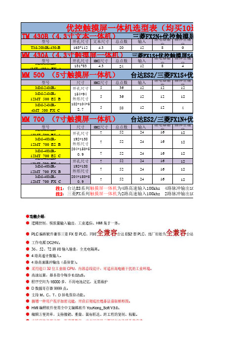
0
0
无 三菱FX1S 398元/台
FX1S+优控触摸屏S500A
温度
AD
0
0
2 路 10K NTC
(-50℃至+150
2
℃)
2 路 K 型热电 偶
2
DA
485通信 PLC软件 价格
0
1路 台达ES2 450元/台
2
无
台达ES2 468元/台
2
无 三菱FX1S 498元/台
FX1N+优控触摸屏S700A
24 24 24
16 16 16
12 12 12
MM-40MR12MT_700_FX_C
204*150*5 0.9
7
52
24
16
12
注1:台达ES系列触摸屏一体机为4路高速输入100khz 4路脉冲输出100khz 继电器输出最大负载 注2:三菱FX系列触摸屏一体机为2路高速输入100khz 2路脉冲输出100khz 继电器输出最大负载
131*83
4.3
24
三菱输入FX1S继+优电出器控输触晶摸体出屏管输S430A
12
8
4
4MT_430A_FX_A
MM 500 (5寸触摸屏一体机) 台达ES2/三菱FX1S+优控触摸屏S500A
型号 MM-24MR-
尺寸 HMI尺寸 总点数
开孔尺寸
5
Байду номын сангаас36
输入 12
继电器输 晶体管输
出
出
12
12
MM-24MR12MT_500_ES_B
HMI尺寸 7
7
总点数 52
52
步科触摸屏usb下载驱动安装说明
步科触摸屏usb下载驱动安装说明(原创版)目录1.步科触摸屏 USB 驱动下载安装概述2.步科触摸屏 USB 驱动下载方法3.步科触摸屏 USB 驱动安装步骤4.步科触摸屏 USB 驱动安装注意事项5.结束语正文步科触摸屏 USB 驱动下载安装说明一、步科触摸屏 USB 驱动下载安装概述步科触摸屏是一种广泛应用于工业人机界面、伺服系统、步进系统、可编程逻辑控制器、低压变频器等领域的触摸屏设备。
为了使步科触摸屏能够正常工作,需要安装对应的 USB 驱动程序。
本文将为您详细介绍如何下载安装步科触摸屏的 USB 驱动。
二、步科触摸屏 USB 驱动下载方法1.访问步科触摸屏官方网站,找到相应的产品页面,选择“驱动下载”选项。
2.在驱动下载页面,选择与您的触摸屏型号相匹配的驱动程序,点击下载。
3.下载完成后,解压缩文件,找到驱动程序所在的文件夹。
三、步科触摸屏 USB 驱动安装步骤1.将步科触摸屏连接到计算机的 USB 接口。
2.计算机会自动识别并安装驱动程序。
如果您的计算机没有自动安装驱动程序,请找到驱动程序所在的文件夹,双击运行其中的安装程序。
3.按照安装向导的提示进行操作,完成驱动程序的安装。
四、步科触摸屏 USB 驱动安装注意事项1.请确保您的计算机已经连接到互联网,以便自动下载驱动程序。
2.在安装驱动程序之前,请务必先关闭触摸屏电源,以免发生短路。
3.安装过程中,请勿断开触摸屏与计算机的连接,以免安装失败。
4.驱动程序安装完成后,建议重启计算机,以确保触摸屏能够正常工作。
总之,安装步科触摸屏 USB 驱动程序较为简单,只需下载对应型号的驱动程序,并按照提示进行安装即可。
十大触控一体机品牌技术参数
目录一、希沃 (1)70寸技术参数 (1)图片示例 (2)二、TCL (3)70寸技术参数 (3)图片示例 (4)65寸技术参数 (5)三、上海广电光显 (6)技术参数 (6)四、长虹 (7)65寸技术参数 (7)五、鸿合科技 (8)70寸技术参数 (8)六、创维光电 (8)70寸技术参数 (9)图片示例 (10)84寸技术参数 (11)65寸技术参数 (12)七、上海仙视 (12)70寸技术参数 (12)图片示例 (14)84寸技术参数 (15)八、夏普 (16)70寸技术参数 (16)80寸技术参数 (17)图片示例 (19)九、创显光电 (19)70寸技术参数 (20)84寸技术参数 (21)图片示例 (22)十、深圳中银科技 (23)70寸技术参数 (23)一、希沃70寸技术参数图片示例70寸图片165寸图片2二、TCL70寸技术参数图片示例70寸图片365寸图片465寸技术参数三、上海广电光显技术参数四、长虹65寸技术参数五、鸿合科技70寸技术参数产品规格:70英寸型号:HD-I7002E背光类型:LED显示比例:16:9可视角度:178°物理解析度:1920*1080Pixel图像制式/声音制式:PAL/DK,I3D功能:——工作电压:AC 90-265V,50/60Hz触摸表面材质:钢化玻璃感应方式:红外感应触摸技术特性:HID免驱触摸点数:多点触控,多点书写书写方式:手指或书写笔触摸分辨率:32767*32767通讯接口: USB存储温度/湿度:-20℃~60℃,10%~90% 工作温度/湿度:5℃~50℃,10%~90% 安装方式:壁挂或移动整机尺寸:1648.9*975.6*112.9mm重量:70KG六、创维光电70寸技术参数图片示例70寸图片565寸图片6七、上海仙视70寸技术参数图片示例八、夏普 70寸技术参数 电力消耗(W ) 230W 待机消耗功率(W ) 0.50电源要求 交流110-240V ,50Hz 屏幕显示语言 英文/中文(简体)/俄语 扬声器 (150mm×34mm )×2音频输出功率 10W×2(AV 输入,负载4欧姆,失真度为10%时) 电视调谐系统 自动预设99个频道视频彩色制式 PAL/SEAM/NTSC3.58/PAL60图像清晰度* RD 模拟信号:水平>=350,垂直>=400以上 SDTV :水平>=450,垂直>=450以上 背光源 LED 重量kg 57.5KG 外型尺寸(cm )宽×深×高 1.625 ×106 ×993mm液晶显示屏 X-GEN 面板分辨力1920(水平)×1080(垂直)下面-数字(天线输入)UHF/VHF 75q DIN 型插座下面-模拟(天线输UHF/VHF 75q DIN 型插座入)后面ー音频输入 HDMI2/电脑共用(直径3.5mm 插孔)RS-232C 9针D-sub 凸型插头电脑 15针小型D-sub,音频输入(与HDMI2共用)(直径3.5mm 插孔)后面—输入5 视频输入,音频输入后面—输入4色差输入(480I,576I,480P,576P,720P/50Hz,720P/60Hz, 1080I/50Hz,10080I/60Hz ),音频输入 后面-HDMI3HDMI(HDMI 输入)(480I,576I,480P,576P,720P/50Hz, 720P/60Hz,1080I50Hz,1080I/60Hz,1080P/50Hz, 1080P/60Hz,1080P/24Hz )侧面-HDMI2HDMI(HDMI 输入)(480I,576I,480P,576P,720P/50Hz720P/60Hz,1080I/50Hz,1080I/60Hz,1080P/50Hz,1080P/60Hz1080P/24Hz)音频输入(与电脑输入公用)(直径3.5mm 插孔))侧面-HDMI 1(ARC )HDMI(HDMI 输入)(480I,576I,480P,576P,720P/50Hz,720P/60Hz,1080I/50Hz,1080I/60Hz,1080P/50Hz,1080P/60Hz,1080P/24Hz ) 侧面-USB2(HDD ) USB2.0 前面 USB12.0侧面ー音频输出/耳机 直径3.5 插孔(音频输出)接收频道 VHF/UHF C1・C12・C13-C57 CATV SECAM/NTSC3.58/PAL60立体声/双语 丽音(NICAM )B/G ,I ,D/K A2 立体声:B/G 接收频率 模拟ATV 44.25-863.25MHz 数字DTV 55.25-863.25MHz电视制式 PAL :B/G,D/K ,I SECAM :B/G,D/K,K/K1 NTSC :M电源 由USB 提供操作系统 Win XP,Win CE,Vista,Win7,Linux,Mac,Android,Win8检测区域 153.9×86.6cmPC 连接器 USB (兼容1.1)书写方式 手指或非透明触控笔触摸定位精度 ± 2mm响应速度(单点连续) 4ms (典型值)触摸点数 6点检测方法 红外线阻隔检测方法80寸技术参数 基本规格电力消耗(W ) 260 待机消耗功率(W ) 0.50 能效指数(EEILCD ) 1.4分辨力1920(水平)×1080(垂直)外型尺寸(cm )宽×深×高 187.6×11.6×113.3液晶显示屏X超晶面板端子DVI-D 端口 1音频输出端子(HP) 1光纤数字音频输出 1Y,Pb,Pr输入端子 1USB端口 2RS-232C端口 1PC输入 1LAN(网络) 无HDMI端口 3复合视频输入端子 2声音声音输出(w) 10W+10W智能光控(opc) 有立体环绕SRS TruSurround HD图片示例九、创显光电图片示例十、深圳中银科技70寸技术参数。
触摸屏控制器用户手册说明书
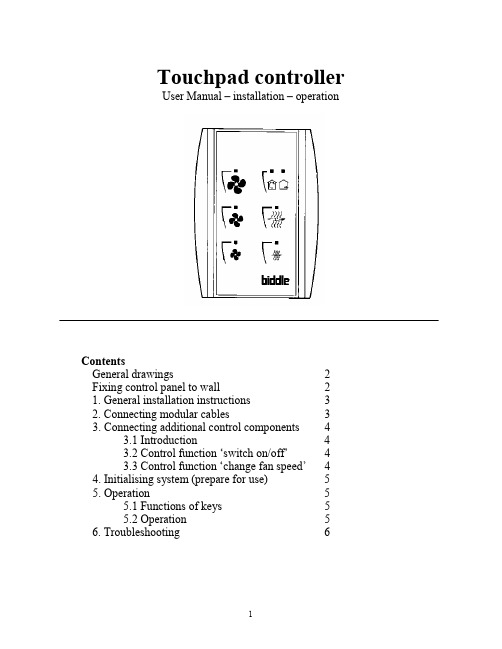
Touchpad controllerUser Manual – installation – operationContentsGeneral drawings2 Fixing control panel to wall21. General installation instructions32. Connecting modular cables33. Connecting additional control components43.1 Introduction43.2 Control function ‘switch on/off’43.3 Control function ‘change fan speed’44. Initialising system (prepare for use)55. Operation55.1 Functions of keys55.2 Operation56. Troubleshooting6Fixing control panel to wall 1234General drawings1. General installation instructions— Read this page carefully before starting the installation.— All installation work must be carried out by expert personnel.— Ensure that the appliances are disconnected from the mains before they are opened.— Avoid unnecessary contact with electronic components.Introduction:1. This manual is intended for all Biddle appliances with a built-in electronic interface.2. This manual describes the installation and use of the Biddle electronic control system.3. Several functions in this manual are only available from a certain version of a control system component. These functions are marked. Whenever you change an existing system you should compare the version number on the component with the version number in the manual.Installation details:1. Up to 10 appliances may be connected to one control panel.2. The total length of all modular cables in one system must be less than 100 metres.3. When installing the modular cable care should be taken to avoid interference with the cable by (electro)-magnetic fields as far as possible (therefore do not lay the cable close to high-voltage cables, fluorescent light starters, etc.)Components:The control system comprises the following components:1. Control panel consisting of 3, 4, 5 or 6 keys.2. Built-in interface with 3 or 6 output contacts, depending on the type of appliance.3. Modular cable including modular plugs, for connecting the control panel to one or more appliances. N.B.: B.T. type telecommunication cables are not suitable! The cable can be ordered from Biddle and is available in various lengths.Installation procedure:1. Connect modular cables + install control panel.2. Connect any customised controls, with control components with potential-free contacts.3. Provide all appliances with a power supply.4. Initialise the system.2. Connecting modular cablesA. Appliances with external connectionsType of appliance:— Modular fan coil unit (PS-B)— Air curtain (KW/MW/GW/KE/ME/GE/CAT/CAT-V)— Cassette air heater (KLV/KLV-E/KLVV)B.Appliances with internal connections Type of appliance:— Fan coil unit (B)— Extractor fan cabinetN.B.: The modular cables (X70) can be connected to both connectors (XiS)(see fold-out sheet, page 2).3. Connecting additional control componentsIf you have no control components to install, you can skip this section and go on to section 4 ‘Initialise the system’.3.1 IntroductionAs well as the basic system functions, there is also a possibility of connecting control components (e.g. room thermostat, timer BMS-controlled relay or door switch) to an appliance. Combinations of control components can also be used.N.B.: For remote switching on blocks X62/X72 volt free contacts are required. These contacts are advised to be gold plated and to have a low relay less than 20 m W to handle 1 mA at 5Vdc.Possible control functions:Control function Control range Adaptation to interface ofconnected appliance Connection points onblock X62/X72Connectionsummaryswitch on/off one appliance (local)none terminals T and G see § 3.2 switch on/off all appliances in system (general)remove jumper 6terminals T and G see § 3.2 change fan speed one appliance (local)none terminals D, P and G see § 3.3 change fan speed all appliances in system (general)remove jumper 5terminals D, P and G see § 3.3 N.B.: The function ‘switch on/off’ does not apply to the KLVV-unit. Consult the user manual of the unit when you want to connect control components to terminals T and G.3.2 Control function ‘switch on/off’1. Remove T-G bridge (X62/X72. see fold-out sheet, page 2) only from the appliance towhich the control component is to be connected.2. Connect the control component between T and G.— Contact made between T and G: Applicance stand-by.— No contact between T and G: Appliance/system off.3. General switching If the control function is to apply to the whole system, remove jumper 6(X64). This should only be done in the appliance to which the control component isconnected. Place the jumper on the reserve positions intended for it (X65), so that it can beused again later.3.3 Control function ‘change fan speed’1. Connect the control component between D and/or P and G (X62/X72, see fold-out sheet, page2). Important: do not disconnect T-G bridge.— Contact made between D and G : Appliance/system runs 1 speed higher than the controlpanel indicates (both speed and electric heating).— No contact between D and G Appliance/system working as indicated on the control panel.— Contact made between P and G Appliance/system runs at fan speed three (electric heatingstage remains unchanged, either one or two).— No contact between P and G Appliance/system working as indicated on the control panel.— Contact made between D, P and G: Appliance/system runs at fan speed three and electricheating stage two.N.B.: The functions using terminals P and G only are available from interface version V4.0Rev.06. Code IC 10 in the illustration on page 2 shows where you can find the version number.2. General switching: If the control function is to apply to the whole system, remove jumper 5(X64) as indicated in the facing illustration. This should only be applied to the appliance towhich the control component is connected. Place the jumper on the reserve positions intendedfor it (X65), so that it can be used again later.NB: General switching’ of the contact between P and G requires control pad version V2. IRev.02 or higher and interface version V4.O Rev.07 or higher. You can find the versionnumber on the printed circuit board of the control pad. In an existing system the control padcould be of a previous version. If the contact between P and G should still apply to the wholesystem, you should order a new control pad from Biddle.3. If the electric heating is not to be stepped up at the same time, remove jumper 4 (X64) asindicated in the illustration. This should be done in each appliance for which the function is required. Place the jumper on the reserve positions intended for it (X65), so that it can be used again later.14564. Initialising the system (prepare for use)When to use:1. On first installation.2. On each extension of the system.3. When checking cables.To start the procedure:1. Press keys 1, 2 and 3 simultaneously.—After 10 seconds the LEDs on keys 1 and 2 will start to flash. This flashing will continue for two minutes.— The LED on key 3 will then flash the same number of times as there are appliances in the system. The system is now ready for use.5. Operation5.1 Functions of keysLED lights when speed setting is ‘low’.LED flashes during initialisation.— Set speed to ‘low’.— Switch off appliance.— Start initialisation.LED lights when speed setting is ‘medium’LED flashes during initialisation.— Set speed to ‘medium’.— Switch off appliance.— Start initialisation.LED lights when speed setting is ‘high’.LED indicates number of appliances connected when initialisation is complete.— Set speed to ‘high’.— Switch off appliance.— Start initialisation.LED lights when electric heating is set to ‘low’.— Set electric heating to ‘low’.— Switch off electric heating.— Set electric heating to ‘low’ and speed to ‘low’.LED lights when electric heating is set to ‘high’.— Set electric heating to ‘high’.— Switch off electric heating— Set electric heating to ‘high’ and speed to ‘medium’.LED-R lights when setting is ‘Recirculate’ or standby.LED-V lights when setting is ‘Ventilate’.— Set air intake valve to ‘Ventilate’.— Set air intake valve to ‘Recirculate’.5.2 OperationA.Turn on appliance : Press key 1, 2, 3, 4 or 5.B.Turn off appliance : Press speed key (1, 2 or 3) on which the LED is illuminated. LED-R (if present) remains illuminated.Safety functions electric heating:1.The following scenarios will automatically be corrected:— Speed off, electric heating on.— Speed low, electric heating high.2. Appliance operates differently from control panel:If the appliance has just been switched off, it may start running again spontaneously.This is in order to discharge the heat stored in the heating elements.6.TroubleshootingAppliance not working:Check point Possible cause Action1no voltage on appliance check power supply to appliance2system not yet initialised start initialisation; see section 4 ‘Initialising the system’3poor contact in modular plug;check contacts (ensure plastic packaging is completely removed)4no bridge between terminals T and G fit bridge between terminals T and G on block X62/72. (see section 3‘Connecting Customised Control components’)5fuse(s) in appliance defective replace fuse (only to be done by skilled personnel)Appliance not working as expected:Check point Fault Possible cause Action/explanation1appliance (with electric heating)starts working spontaneously continued running of electricallyheated appliancesBiddle safety function; see section 5‘Operation’control components are notproperly connectedcheck system; see section 3‘Connecting Customised ControlComponents’2appliance works differently fromexpectationthe jumpers(l-3 red) on the interface are no longer in accordance with factory setting check jumper position against Specifications for factory setting jumper block X643electric heating not working appliance has overheated check maximum thermostat(see appliance manual) Factory setting jumper block X64Appliance type Jumper 1Jumper 2Jumper 3Jumper 4-6 appliance with electric heating with 2 positions present open present present CAT-air curtain open present present present KLV-E open present open present KLVV open open open presentall other appliances present present present present。
深圳为胜智控技术有限公司触摸屏一体机产品使用说明书

触摸屏一体机产品使用说明书--V1.6适用于以下型号:4.3寸7寸WS4312R WS7020RWS4312T WS7020TWS4320R WS7040RWS4320T WS7040TWS4322R WS7048RWS4322T WS7048T产品目录第一章产品概述 (1)1.1产品概述 (1)1.2基本参数 (1)1.3外形尺寸及安装方法.............................2-3第二章产品展示 (4)2.1产品主要硬件说明 (4)2.2产品效果图 (5)第三章触摸屏参数及编程说明 (6)3.1触摸屏基本参数 (6)3.2触摸屏编程说明 (7)3.3触摸屏与PLC通讯说明 (7)第四章PLC电气设计参考 (8)4.1电源及功耗 (8)4.2232通讯口说明 (8)4.3485通讯口说明...................................8-94.4与变频或仪表通信 (10)4.5模拟量输入输出说明............................10-114.6时钟模块说明 (12)4.7PID运算指令说明 (12)4.8高速计数 (12)4.9高速脉冲输出与脉宽调制 (13)4.10中断说明 (13)4.11产品接线图 (14)第五章PLC编程参考 (15)5.1应用环境 (15)5.2软元件功能概要 (15)5.3基本指令 (16)5.4应用指令......................................16-195.5此版本不支持指令列表 (19)第六章常见问题及解决方案 (20)第七章保修条款 (20)第一章产品概述1.1产品概述触摸屏部分:·采用32-bit240MHz ARM9CPU,运算速度快。
·高清LCD屏,26万真彩显示;·4线工业电阻触摸屏(表面硬度4H);·支持U盘下载;·使用为胜HMIStudio软件编程。
触摸屏用户手册说明书
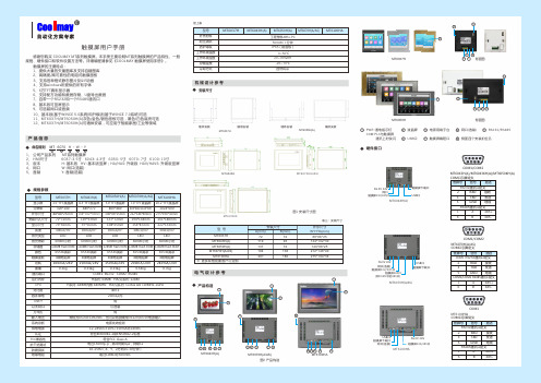
感谢您购买 COOLMAY MT 系列触摸屏。
本手册主要说明MT 系列触摸屏的产品特性、一般规格、硬件接口和软件设置方法等。
详细编程请参见《COOLMAY 触摸屏使用手册》。
触摸屏的主要特点:1、提供大量的矢量图库及支持自建图库2、高精度/高可靠性的电阻式触摸面板3、支持各种格式静态图片及GIF 动画4、支持windows 所提供的所有字体5、6万TFT 真彩显示器6、支持配方功能和数据存储、U 盘导出数据7、自带一个RS232和一个RS485通讯口8、基本版可竖屏显示9、可选装网口或音频10、基本版(基于WINCE 5.0系统)和升级版(基于WINCE 7.0系统)可选11、MT6037H /MT6050H (A )灰色/金色/银色面板可选,黑色/白色底壳可选 12、MT6037H /MT6050H (A )可墙体安装,可应用于智能家居/工业等领域产品信息1、 公司产品系列 MT 系列触摸屏2、 HMI 尺寸 6037:3.5寸 6043: 4.3寸 6050: 5寸 6070: 7寸 6100: 10寸3、 版本 H : 基本版 HV : 基本版竖屏;HA /HAS : 升级版 HAV /HAVS : 升级版竖屏4、 网口 W : 网口(选装)5、 音频 Y : 音频(选装)命名规则MT 123456070图1 安装尺寸图MT6100HAMT6043HMT6070H(A/AS)电气设计参考产品构造COM :PLC 与触摸屏 通讯上时快闪安装尺寸机械设计参考规格参数触摸屏用户手册表三:安装尺寸型 号安装尺寸外形尺寸W*H*D(mm)A(mm)B(mm)MT6050H(A)MT6070H(A/AS)MT6100HA13719426172138180146*88*25212*148*40275*194*36电源用端子台 USB 口PWR :通电指示灯触摸屏编程口液晶屏RS232/RS485网口(选装) ◆◆◆◆YW H--6143257图2 产品构造※ 更多规格批量客户可定制MT6043H(A)MT6070H(A/AS)MT6100HAMT6037H背面图MT6050H背面图型号MT6037H 3.5"TFT 液晶屏 4.3"TFT 液晶屏7.0"TFT 液晶屏10.2"TFT 液晶屏MT6043H(A)MT6070H(A/AS)MT6100HA 320*240480*272800*480/1024*6001024*60088*88*25mm 134*102*30mm 212*148*40mm 275*194*36mm 72*72mm 119*93mm 194*138mm 261*180mm 73*56mm 97*56mm 154*87mm 222*133mm 300cd/m²300cd/m²300cd/m²300cd/m²LED LED LED LED 128MB Flash ROM 65536真彩4线电阻屏100mA/24V150mA/24V200mA/24V280mA/24VCOM1: RS232 COM2: RS485400:1H 系列: ARM9内核 640MHz HA(S)系列: Cortex A8 720MHz-1GHz20ms 以内有电源失效检测12-24VDC ±10%<150mA @24VDC 符合EN50081-2和EN50082-2标准符合FCC Class A电压1500Vp -p ,脉冲周期1μs ,持续1s 10-25Hz (X 、Y 、Z 方向2G 30分钟)超过10M Ω@500VDC工程塑料ABS +PC 500VAC 1分钟IP65(前面板)0~50℃20~90%RH -20~70℃显示屏分辨率外形尺寸安装开孔尺寸显示尺寸亮度背光类型存储器颜色触摸面板功耗通讯端口对比度CPU 容许掉电USB??系统诊断供电电源认证FCC 兼容性抗干扰测试防震测试绝缘电阻外壳材料耐压测试防护等级工作环境温度工作环境湿度存储温度65536真彩4线电阻屏65536真彩4线电阻屏65536真彩4线电阻屏0.3kg0.33kg0.54kg0.7kg重量MT6050H(A)5.0"TFT 液晶屏800*480146*88*25mm 137*72mm 108*65mm 300cd/m²LED 150mA/24V65536真彩4线电阻屏0.33kg128MB Flash ROM 128MB Flash ROM 128MB Flash ROM 128MB Flash ROMH 系列: 64MB HA(S)系列: 128M运行内存121264357643572264357673541234657侧面四个安装扣位孔888888MT6037H 727288*88*25MT6043H(A)11993134*102*30MT6037H硬件接口◆FG 0V 24V触摸屏232/485口触摸屏下载口USB口网口COM1/COM2MT6043H(A)/MT6043KH(A)/MT6050KH(A) COM口引脚定义管脚号信号描述23TXDRXD 发送接收5地线GNDRS232通讯口定义RS485通讯口定义16BA485-485+MT6043H(A)背光寿命60000小时60000小时60000小时60000小时60000小时以太网口可选装万年历输入电压有常规为DC24±10%VDC ,也可以特别做成DC12V /DC5V 电源输入墙体安装镶嵌安装墙体安装镶嵌安装MT6050H(A)型号MT6037H MT6043H(A)MT6070H(A/AS)MT6100HAMT6050H(A)自然风冷冷却方式接上表FG 0V 24V 触摸屏485口USB口触摸屏下载口触摸屏232/485口网口(选装)(同COM1中的485口)COM1/COM2MT6070H(A/AS ) COM口引脚定义管脚号信号描述23TXDRXD 发送接收5地线GNDCOM1 RS232通讯口定义COM1/COM2 RS485通讯口定义16BA 485-485+MT6070H(A/AS)FG 0V 24V USB口触摸屏下载口网口(选装)触摸屏232/485口COM1MT6100HACOM口引脚定义管脚号信号描述23TXDRXD 发送接收5地线GNDRS232通讯口定义RS485通讯口定义16BA 485-485+MT6100HA* 编程软件触摸屏:CoolMayHMI 触摸屏编程软件* 详细资料参考《CoolMayHMI 触摸屏使用手册》温馨提示.......................................................01产品特点.......................................................02产品信息.......................................................03 电气参数......................................................04 机械设计参考................................................05 产品构造.......................................................06 硬件接口.......................................................07软件参数设置................................................08 与个厂牌联机说明.........................................09 抗干扰处理...........................................10 编程参考.......................................................11资料参考. (12)深圳市顾美科技有限公司 86960332 26051858 26400661营销QQ:800053919邮箱:**************.com 网址:2018/02 版目 录1、请在确认了本产品的电源电压范围(常规产品电源仅限24V?DC!建议电源的 输出功率为18W及以上)和正确接线之后再通电,以避免损坏。
科悠电子 可编程触摸屏HMI软件HMI系列说明书

350Visit our websitehttp://www.koyoele.co.jp/english/KOYO ELECTRONICS INDUSTRIES CO., LTD.GENERAL CATALOG 2016Latest catalog (free) is available online.HMI Lineup*1 To be supportedP L C351KOYO ELECTRONICS INDUSTRIES CO., LTD. GENERAL CATALOG 2016The specifications and prices described in this catalog were valid when the catalog was issued.For the latest information, contact our sales persons or see our website.HMI Lineup352Visit our websitehttp://www.koyoele.co.jp/english/KOYO ELECTRONICS INDUSTRIES CO., LTD.GENERAL CATALOG 2016Latest catalog (free) is available online.GC-7EA7GC-A Features Programmable Touch Panel TFT models from 7-inch WVGA Screen transfer: Ethernet / USB PLC connection: Ethernet / Serial Supports SD card Macro features Supports remote operation Features Remote operation on a smartphone/tablet It transfers GC-A screens on a mobile devices to enable the operation of applications remotely. This remarkably improves safety and efficiency at workshop because the remote access enables updates and/or troubleshoots of lines at everywhere.Email server feature Serves emails indicating troubles at workshop to the of ce or any places. So maintenance capability will be drastically enhanced because you can grasp the trouble situation immediately.Nimble data management with SD card (to be supported)Easily moves screen data and enables analyzing the data records on the panel with a PC at the of ce in order to prepare business reports, so that you utilize the accumulated operation records much more easily.Advanced programming Received data can be processed with various programmable conditions and data transaction features. Since touch panel processes data to display and to analyze, it reduces PLC's processing load and saves communication overhead as well. Displays with WVGA LCD Displays clear vivid images with high resolution WVGA LCD device. Implemented 7 inch wide screen that is installed in a same size of 5.7 inch model housing is suitable for compact and integrated management machines.Low power consumption for cost saving LED backlight saves rated power consumption to around 6 watts. Also 7 level brightness control feature helps extra power saving.Saves maintenance costs Removing a cooling fan and adopted excellent quality parts eliminate required replacement parts and reduce the running costs. So the ecological capability brings outstanding cost merits throughout long-term running.Various interfaces for external devices For PLCs, provides Dsub 15pin RS-232C/422/485 port, Dsub 9pin RS-232C port and RJ45Ethernet port for 10Base-T/100Base-TX communication. And for project (screen) transfer, it has a built-in USB2.0 Type B port. Further, offers a reasonable model without Ethernet communication port in the product lineup. Software Outline Menu BarPrepared useful features such as Windows interfaces. Window Windows that are used to operate standard features can be located anywhere to customize it. Toolbar Toolbars at the end of window can be moved to be used as toolbox. Con figuration Window Place various parts to prepare screen for speci c purpose.P L C 353KOYO ELECTRONICS INDUSTRIES CO., LTD. GENERAL CATALOG 2016The specifications and prices described in this catalog were valid when the catalog was issued.For the latest information, contact our sales persons or see our website.GC-7EA7GC-ASpecifications Each Part Names and Descriptions1 Power supply (24 V DC) Drives with useful power supply2 SD card slot Used for uploading/downloading screen data and saving measured data.3 Serial port 2 Makes connection with the PLC possible.4 Serial port 1 Makes connection with the PLC possible.5 USB B port Screen data can be uploaded/downloaded.6 USB A port Measured data can be saved in a USB memory that is convenient to carry around.7 Ethernet port Makes connection with the PLC possible.5 USB A port5 USB B port7 Ethernet portStatus LED 4 Serial port 12 SD card slot1 Power supply (24 V DC) 3 Serial port 2Back side Back side bottom354Visit our websitehttp://www.koyoele.co.jp/english/KOYO ELECTRONICS INDUSTRIES CO., LTD.GENERAL CATALOG 2016Latest catalog (free) is available online.GC-7EA7GC-A Specifications*1 25 degrees C, 24 hour continuous lighting *5 Some of commercial products may not work with this *2 Any one of RS-232C/422/485 can be used. *6 Option EA-AC speci cation *3 Combined use by PLC connection and screen data transfer and the network *7 Disabled while using Ethernet*4 Neighbor port may not be available according to width of plug shapeP L C355KOYO ELECTRONICS INDUSTRIES CO., LTD. GENERAL CATALOG 2016The specifications and prices described in this catalog were valid when the catalog was issued.For the latest information, contact our sales persons or see our website.GC-7EA7GC-ASpecifications Dimensions DimensionsEA-AC+1−0356Visit our websitehttp://www.koyoele.co.jp/english/KOYO ELECTRONICS INDUSTRIES CO., LTD.GENERAL CATALOG 2016Latest catalog (free) is available online.GC-AEA7GC-7Features Programmable Touch Panel (GC Type)Inherited the GC-5 display.- 10.4-inch TFT color Model number: GC-76LC - 5.7-inch STN color Model number: GC-73LCL-R - 5.7-inch STN monochrome Model number: GC-73LM-R Features - Shifted from the GC50 series. The applications of the GC-50 series (GC-53LC3, GC-53LM3, and sGC-56LC2) are partially inherited. The applications can be replaced within restrictions. Restrictions from the GC50 Series 1. Drawing software Prepare ScreenCreator5 Ver3.0 or later. You can download the drawing software from Koyo Electronics' website free of charge.2. Panel cutout dimensions The panel cutout dimensions are not changed. The display can be installed in the existing holes for attaching the control panel as is.3. Dimensions The 5.7-inch type is 7.1 mm thicker in depth. The 0.4-inch type is 3.0 mm wider in width. Since the location and size of mounting brackets and external connection connectors are different, make sure that there are no interfering parts inside and outside the board.4. Power Supply The 5.7-inch type is connected to the main body, not by terminal block but by connector (bundled item). The 10.4-inch type has been changed to 24 V DC speci cation. If you use the GC7 at 100 V/200 V AC, use the optional EA-AC or prepare a commercial AC/DC power supply. (If the EA-AC is used, the depth of the product becomes the main body + 36.1 mm.)5. Con firmation of PLC models PLCs that can be used are largely limited. Also, the shapes of connection connectors are different. (M:N communications also cannot be used.)6. Con firmation of peripheral devices The GC70 series has only one serial port. Also note that there are no parallel ports or RAS output / reset input. - ScreenCreator5 is usable. The ScreenCreator5 drawing software has been upgraded. You can draw in the same way as with the GC-50 series.7. Touch panel operation Since an analog-type touch panel is used, there are the following restrictions. - You cannot press two, three, or four points at the same time. - The resolution of the touch panel is different. Since the GC50 series has a different resolution (16 x 12 or 32 x 24) from the GC70 series (1,024 x 1,024), the operational feeling may be different.8. When K-BASIC is used There are restrictions on usable instruction words.9. When option products are used The digital I/O cannot be used. The backup data in a CF card is not compatible. If the data is backed up by a CF card for the GC50 series, restore the screen data to ScreenCreator5 once. Each setting data needs to be reset for the GC70 series.10.How to download screen data Screen data can be transferred via USB.11.OtherThere may be restrictions in addition to the items mentioned above.Viewingangle of the screen, appearance of reduced / enlarged characters, appearance of the black-and-white type (difference between blue type LCD and black-and-white mode), etc. * When you change models, it is recommended that you check the operations using actual equipment once.P L C357KOYO ELECTRONICS INDUSTRIES CO., LTD. GENERAL CATALOG 2016The specifications and prices described in this catalog were valid when the catalog was issued.For the latest information, contact our sales persons or see our website.GC-A EA7GC-7Specifications How to Transfer SoftwareRead the screen data project usingScreenCreator5 (Ver3.0 or later).Change the target panel to the new model (GC-73LM-R / GC-73LCL-R / GC-76LC) usingScreenCreator5 (Ver3.0 or later).Recompile the screen data using ScreenCreator5 (Ver3.0 or later).Download the compilation data to the new model using ScreenCreator5 (Ver3.0 or later).* In a new model, it is not necessary to change to the download mode at hardware side like previousmodels.If the computer and the display are connected via a USB cable and the data is downloaded from acomputer, the display automatically changes to the download mode and automatically restarts afterthe completion of the download.Each Part Names and Descriptions1 Power supply (24 V DC) Can be used for the power supply in the same conditions as GC-53L 3.2 CF card slot The screen data can be uploaded/downloaded from a CF card.3 AC power supply module (Option) Can be used with a power supply under the same conditions as the GC-56LC2.4 Various LEDs You can check the power supply / status / transmission and reception.5 Battery Retain clock data / SRAM.6 Serial port For connection to a PLC7 USB A port The screen data can be uploaded/downloaded from a USB memory.8 USB B port The screen data can be uploaded/downloaded from drawing software.Cable length: 3 mNot in Use4 Various LEDs3 AC Power Supply Module (Option)7 USB A Port8 USB B Port5 Battery6 Serial Port2 CF Card Slot 1Standard Expansion (Option is installed)358Visit our website http://www.koyoele.co.jp/english/KOYO ELECTRONICS INDUSTRIES CO., LTD.GENERAL CATALOG 2016Latest catalog (free) is available online.GC-AEA7GC-7Specifications*1 Since this display uses a cold-cathode tube for the backlight, the brightness widely uctuates according to the conditions shown below. Consider the described brightness as a target. Ambient temperature, installation angle of the product, elapsed time since power-on, duration of use of the product, and number of product power supply ON/OFF cycles *2 Only the speci c card can be used. * Regarding the EA-AC speci cations, see P.345.P L C 359KOYO ELECTRONICS INDUSTRIES CO., LTD.GENERAL CATALOG 2016The specifications and prices described in this catalog were valid when the catalog was issued.For the latest information, contact our sales persons or see our website.GC-A EA7GC-7SpecificationsSupported PLCs as of May 2012Largely restricted compared with the GC50 series.If devices other than those above are connected, it is impossible to shift to the GC70 series.360Visit our websitehttp://www.koyoele.co.jp/english/KOYO ELECTRONICS INDUSTRIES CO., LTD.GENERAL CATALOG 2016Latest catalog (free) is available online.GC-A EA7Hole12.1inch15.0inchP L C 361KOYO ELECTRONICS INDUSTRIES CO., LTD.GENERAL CATALOG 2016The specifications and prices described in this catalog were valid when the catalog was issued.For the latest information, contact our sales persons or see our website.GC-A EA7GC7Correlation362Visit our websitehttp://www.koyoele.co.jp/english/KOYO ELECTRONICS INDUSTRIES CO., LTD.GENERAL CATALOG 2016Latest catalog (free) is available online.GC-A GC-7EA7FeaturesProgrammable Touch Panel- Full line-up of TFT models from 5.7-inch to 15.0-inch The 5.7-inch type has a STN black-and-white model.- Screen transfer: Ethernet / USB - PLC connection: Ethernet / Serial- Screen storage media: Built-in memory / Expansion CF - Sound output: Equipped as a standard (Excluding the EA7-S6M-RS, EA7-S6M-RS)- Protection level: IP65FeaturesVarious Files Can be Used.Since various les such as image les (bmp) and audio les (wav) can be used, you can create more realistic screens.Abundant ComponentsVarious components can be graphically expressed.Easy Downloads / UploadsWith no wasteful settings, you can immediately upload/download data by selecting a button. Owing to the USB and Ethernet connections, a long transfer time is not required.Large-size Screen DisplayThe 15-inch screen can display large characters that are easily visible.Simulation on ComputerScreen operation can be checked from a computer without the actual equipment. It is not necessary to prepare and connect the actual equipment to perform the simulation on the computer.Password SettingAll patterns of password settings can be performed on one screen.Since the password can be set on eight levels, it is easy to create screens such as one that can be operated only by the administrator.Software Outline3 Step BarYou can select what to do now from the start of a project to the mounting to displays by pressing the Step1 Start, Step2 Simulation, and Step3 Send buttons.Navigation WindowThis window shows details of the screen, important menus of the ViewJetCmore software, etc.Con figuration WindowThe components can be selected by pushing one button and can even be overlap. Enjoy the free space.List WindowYou can select from various components at a glance. By dragging components to the drawing window, you can create screens as you wish.Parts List WindowThis window shows parts design that corresponds to the list of objects.Multilingual UtilizationA combination of up to nine languages or fonts can be registered.*1 The characters displayed on the screen can be switched according to patterns. Since characters are only changed on the same screen, the number of screens can be minimized.Supported languages: Japanese, Chinese, Taiwanese, English, Korean, Spanish and Thai*1 When one language will be additionally used, the CF card needs to be added. (Example: Japanese and Chinese)Use of Memory CardsThe data can be exchanged using a memory card. Since no computer is needed for the operation, the operator can work under reduced burden.Use of CSV FilesSince the data managed by ViewJetCmore (tag, message, alarm, and language) can be stored and edited in CSV format, you can edit the data in a familiar environment.View of the Display ScreenThe screen data installed in the display can be viewed on computers and PDAs from a remote place. Other than the screen currently displayed, the backside screen can also be viewed.Setting Up Connected DevicesThe connections of ViewJetCmore or PLCs can be visually checked and set. The connected devices can be easily set without wondering what to do.Common to all model number - Touch panelAnalog resistive type - CE marking compliantP L C 363KOYO ELECTRONICS INDUSTRIES CO., LTD.GENERAL CATALOG 2016The specifications and prices described in this catalog were valid when the catalog was issued.For the latest information, contact our sales persons or see our website.GC-A GC-7EA7SpecificationsEach Part Names and Descriptions1 Power supply (24 V DC) The slim body drives the display.2 AC power supply module Can drive the display around the world according to the environment.3 CF card slot 1 Used for uploading/downloading screen data and saving measured data.4 CF card module For saving larger-capacity data. (Option)5 CF card slot 2Used for saving measured data.6 Extended module adapter Expansion-adapter for 4CF card modules.7 Ethernet port Enables screen data uploads/downloads, uploading of measured data, and connections with PLCs at high speed. 8 USB A port Measured data can be saved in a USB memory that is convenient to carry around.9 USB B port Screen data can be uploaded/downloaded. The data can be exchanged comfortably at high speed.10 Audio output Noti ed not only by displayed alarms but also by sound.11 Serial port Makes connection with the PLC possible.Example of the Utility3 CF card slot 1[Example of data that can be used in CF cards] Screen data, Logging data 5 CF card slot 2 [Example of data that can be used in CF cards] Logging data 9 USB A port[Example of data that can be used in USB memorys] Logging data4 CF Card Module5 CF Card Slot 26 Extended Module Adapter2 AC Power Supply Module10 Audio Output7 Ethernet Port11 Serial Port8 USB A Port9 USB B Port Power Supply(24 V DC)Status LED3 CF Card Slot 1CF CoverExpansion Module CoverStandard ShapeMaximum Expansion ShapeExpansion (Option is installed)Maintenance Product364Visit our websitehttp://www.koyoele.co.jp/english/KOYO ELECTRONICS INDUSTRIES CO., LTD.GENERAL CATALOG 2016Latest catalog (free) is available online.GC-A GC-7EA7Specifications* The computer must have an USB (A) port or Ethernet port.P L C365KOYO ELECTRONICS INDUSTRIES CO., LTD.GENERAL CATALOG 2016The specifications and prices described in this catalog were valid when the catalog was issued.For the latest information, contact our sales persons or see our website.GC-A GC-7800 x 600 (SVGA)1,024 x 768 (XGA)4,096 W x 4,096 H17 W or lower 20 W or lower 33 W or lower 299 W x 209 H x 70 D 339.5 W x 280.0 H x 52.7 D 396.8 W x 310.8 H x 52.0 D 148019803030285 W x 191 H319.5 W x 260.0 H374.0 W x 288.0 HQSG (Quick Start Guide) manual Mounting brackets (8 units)Power plug100/200 V AC 85 to 240 V AC Within 40 msMaximum 64 VA 0 to 50˚C -20 to 60˚C10 to 85% RH (No condensation)1000 V AC p-p, pulse width 1 μs, rise time 1 ns (Cased on noise simulator)1000 V AC, 1 min, between AC power supply input terminal and FG terminal 20 MΩ or higher (500 V DC), between AC power supply input terminal and FG terminal Comply with IEC61131-2, 10 to 57 Hz: 0.075 mm, 57 to 150Hz: 9.8 m/s 2 (10 times each for the X, Y, and Z direction)Maximum 147m/s 2 11ms (2 times each for the X, Y, and Z direction)Compliant with IEC61000-4-2, contact: 4 kV, air: 8 kV No corrosive gases D-class grounding90.3 W x 76.2 H x 36.1 D*6170Natural air-coolingUL508, EMC directive (CE marking; Self-declared), CE EN61131-2Operation manual, Power plug*1 Average life: Continuous lighting for 100,000 hours or longer/25˚C, 24 hour continuous lighting *2 Any one of RS-232C/422/485 can be used. *3 Combined use*4Only connectible devices are some commercially available keyboards, barcode readers, and memory cards.*5 0 to 40˚C in the case of EA7-T15CL-S*6 Dimensions when attached to the main body of display *7 Error tolerance +1 mm, -0 mm.EA7SpecificationsCable length: 3 m366Visit our websitehttp://www.koyoele.co.jp/english/KOYO ELECTRONICS INDUSTRIES CO., LTD.GENERAL CATALOG 2016Latest catalog (free) is available online.GC-A GC-7EA7SpecificationsFor the details about supported PLCs, contact our customer support center.*1 The Q00CPU, Q00JCPU, and Q01CPU are not supported.Barcode ReaderP L C 367KOYO ELECTRONICS INDUSTRIES CO., LTD.GENERAL CATALOG 2016The specifications and prices described in this catalog were valid when the catalog was issued.For the latest information, contact our sales persons or see our website.GC-A GC-7 DimensionsEA7Dimensionsinch inch inch 10.4inch 5.712.1inch15.0inch8.4inchinch5.712.1inch 15.0inch 8.4inch 5.712.1inch 15.0inch 8.4inch 10.4inch。
维控人机界面初级教程

初级教程的内容1. 软件帮助在哪里:32. 软件版本:33. Usb线的类型(D口、一口、迷你口)44. 232的下载线接线:65. 串口引脚的定义:66. 各个型号的com口(com1和com2、com3)77. 下载时的工具选择(PC端口)98. 测试界面的进入及内容9(1)怎样进入触摸屏的测试画面?9(2)COM口参数设置11(3)时间设置13(4)触摸屏版本信息的查看?15(5) 触摸屏按键位置不准确,该怎么办?169. u盘根目录和u盘升级文件:1710. 画面的复制:1911. 画面属性的设置:2012. 子画面的制作2113. 画面(部件)安全等级:2214. 脚本的使用和分类:24画面脚本(实现当前画面效果的脚本)24全局脚本:24背景脚本:2515. 部件叠放顺序的使用:2516. 工程所有使用过的部件列表在哪里:2617. 字位开关的使用:2718. 流动部件使用:2919. 多重复制3020. 键盘制作使用的部件3121. 向量图的修改3722. 外观位图的修改3823. 透明操作4024. 字体的编辑4325. 部件对齐排版4526. 批量修改相关属性:451.软件帮助在哪里:-------------->:1.软件打开,按F1键2.软件工具栏上“帮助”。
2.软件版本:---------------->: 打开软件----------关于(查看时间和版本号)3. Usb线的类型(D口、一口、迷你口)------------------>:430T,777Tb接口:用于下载工程文件、配方或者镜像文件,u盘数据下载。
------------------>:777A,102A1.D型口:用于下载工程文件、配方或者镜像文件;b接口:用于u盘数据下载。
------------------>:908T,104T背面实物图:b迷你口:用于下载工程文件、配方或者镜像文件;b接口:用于u盘数据下载4. 232的下载线接线:----------------->:交叉接线2-----------------33-----------------25-----------------55. 串口引脚的定义:-------------->: 串口的引脚分别有9针、15针和25针的三种类型。
触摸查询一体机触摸屏驱动及USB驱动安装说明书

触摸查询一体机触摸屏驱动及USB驱动安装说明书触摸查询一体机触摸屏驱动及USB驱动安装说明书1.安装/卸载下载适合触摸屏的驱动文件,运行驱动包中的“Setup.exe”文件,就能快速安装上触摸屏驱动。
双击“Setup”单击“下一步”单击“完成”,驱动程序安装完成。
完成后弹出校正屏幕界面,用手指轻触屏幕上的圆点校正屏幕,校正完成后点击“确定”退出程序。
如果要重新校正触摸屏,请您点击“开始”菜单,指向“所有程序”,然后再指向“益图电子USB驱动”,点击“校正程序”,或者点击“开始”菜单,打开电脑的“控制面板”,然后双击触摸屏控制面板图标即图标“Etwotouch 设置”,您就能在相应的窗口修改触摸屏设置。
要注意的是,如果Windows XP系统的控制面板为分类视图,请您切换到经典视图,这样才能看到“Etwotouch 设置”。
如果想卸载触摸屏驱动,请点击“开始”菜单,指向“程序”,然后再指向“益图电子USB驱动”,点击“卸载驱动”。
安装触摸屏驱动后,您可以任意改变触摸屏的USB接口。
如果还没有校正触摸屏,请校正。
校正后就能正常使用我们的触摸屏。
2.安装包中文件的说明该触摸屏驱动安装包包含了以下文件:1.ettusb.sys , USB口触摸屏的驱动文件 ettfilt.sys2.ettusb.inf,ettfilt.inf 触摸屏驱动安装和配置文件3.ettcplusb.cpl 触摸屏控制面板4.uninst.exe 触摸屏卸载程序5.ettcal.exe 触摸屏校正程序触摸屏驱动安装向导,使用该文件6.setup.exe 快速又容易地安装驱动。
7.readme.htm 该文件您正在阅读,多谢合作。
3. 注意事项本驱动要求当前使用系统有鼠标类驱动“MOUCLASS.SYS”和HID类驱动“HIDUSB.SYS”。
这个两个文件是系统自带的,如果这两个文件丢失或者损坏,本驱动将不能正常工作。
请使用如果触摸屏出现点击无反应,外接PS/2接口的键盘和鼠标,重新安装触摸屏驱动程序即可解决。
教学触摸一体机解决方案

自动声音标准检测,支持平衡调节,环绕
2*10W 1路USB2.0 2路 1路 1路 1路 1路 1路 AC100-240V 50/60Hz (External) ≤5W
教学触摸一体机
触摸屏参数
感应技术 触控模式 感应物体 感应大小 分辩率 响应时间 红外感应方式 单点、多点、鼠标三种模式可热切换 手指、笔等任何不透明物体 直径大于等于5mm,推荐大于等于7mm 4096*4096 单点模式:首点(点击):8ms ,连续(书写):3ms 多点模式:首点(点击):8ms ,连续(书写):8ms 鼠标:首点(点击):8ms ,连续(书写):8ms
教学触摸一体机
移动支架式
安装样式
嵌入式
壁挂式
教学触摸一体机
液晶电子白板+组合推拉黑板
教学触摸一体机 应用软件特点
电子白板应用软件是功能强大的多媒体课件和教案制作工具, 专门为互动教学和展示领域设计,与液晶触摸屏完美结合,实 现自由书写、绘画涂鸦、编辑公式、手写识别、视频播放、等 强大的多媒体效果。通过它,可以轻松创建生动的课堂方案, 更好的更全面实现多媒体互动教学。电子白板应用软件采用嵌 入式图文菜单设计,界面友好,操作简单易学,人机互动性强。 系统可以和其他任何软件兼容。 图形编辑功能 画笔和板擦功能 手绘图形自动识别功能 魔术笔 动画特效(课件制作功能) 图标功能 多媒体播放 记录回放功能 函数功能 资源管理 学科工具
优势——与传统教学模式对比
◆改变传统的教学模式(黑板+粉笔) ◆克服传统教学模式的缺点 ◆减少传统教学中的污染并且保护教师和学生的健康
教学触摸一体机 —— 教育应用 在教学模式中的优势
优势——与多媒体电化教学模式对比 ◆高度集成电脑、投影、幕布、显示器、音响,安装简单,操作方便
信捷触摸屏U盘导入工程画面操作说明

触摸屏U盘导入工程画面操作说明要求:支持U盘导入工程画面的触摸屏为TG、TE以及TN系列触摸屏且下位机版本为V2.D.3c及以上,画面编辑软件必须是V2.D.3K及以上版本。
操作前请查看所使用触摸屏背面铭牌上的版本信息及所用软件版本。
见下图:当所用触摸屏支持U盘导入工程画面时分为以下两种情况操作:一、触摸屏内工程画面用的编辑软件是V2.D.3f,导入工程画面请参见方式一。
二、触摸屏内工程画面用的编辑软件是V2.D.3i及以上版本,导入工程画面请参见方式二。
如果不确定触摸屏中工程是用哪个软件版本建立的,可以尝试用方式二操作,如果没有步骤3中的导入工程,则请按方式一导入。
两种方式主要区别是要导入的工程文件名是否可选:方式一导入的文件名必须是默认 Export.dat,不可修改,不可选择;方式二导入的文件名可修改,U盘里可有多个工程文件供选择下载。
方式一1、编辑画面程序。
按正常步骤新建工程编辑画面内容。
如新建一个工程如下图所示,2、导出工程。
选择文件-导出工程,出现保存路径如下图所示:此种方式下文件名必须为Export.dat,选择U盘所在路径,点击保存即可。
3、导入工程画面。
将U盘插入触摸屏U盘口,然后将触摸屏背面拨码开关2号拨码拨至ON,上电重启,则出现以下画面:等待程序导入,当听到滴滴两声响时表明导入完毕。
将2号拨码拨下来,上电重启即可进入工程画面正常工作。
方式二1、编辑画面程序。
按正常步骤新建工程编辑画面内容。
如新建一个工程如下图所示,2、导出工程。
选择文件-导出工程,出现保存路径如下图所示:此种方式下文件名可自行修改,建议文件名不要太长,8个字符以内,否则文件名会显示不完全,文件类型必须是.dat,选择U盘所在路径,点击保存即可。
3、导入工程画面。
将U盘插入触摸屏U盘口,然后将触摸屏背面拨码开关3号拨码拨至ON,上电重启,则出现以下画面:点击导入工程,屏上会显示出所有的.dat格式文件,选中xinje.dat文件,点击灰色向右导入箭头,即可导入选中工程,如下图所示:当绿色进度条满格时导入完成,把3号拨码拨至OFF,上电重启,即可正常工作。
- 1、下载文档前请自行甄别文档内容的完整性,平台不提供额外的编辑、内容补充、找答案等附加服务。
- 2、"仅部分预览"的文档,不可在线预览部分如存在完整性等问题,可反馈申请退款(可完整预览的文档不适用该条件!)。
- 3、如文档侵犯您的权益,请联系客服反馈,我们会尽快为您处理(人工客服工作时间:9:00-18:30)。
FX-TK04U-V3.1 USB 触摸屏控制器
TK04U-V3.1 规格书说明包含:
•电气特性l
•使用环境
•外观尺寸
电气特性
电源
•电压+5 Vdc (+4.4 to +5.25 Vdc)
•电流100 mA, +5 Vdc 功耗0.2 W.
•供电电源最小供电电流300 mA.
•供电电源纹波和噪声频率低于1MHZ,峰峰值要求小于100 mV (p-p) , 频率高于1MHZ, 峰峰值要求小于50 mV (p-p) .
接口
•支持USB通讯.
•USB
o兼容USB 1.1, USB2.0 全速设备.
o支持挂起和远程唤醒
操作模式
•桌面
•划线
•按键
响应时间
•240pps
串形通信协议
•UTCP : 默认USB,l
•MT TM : MT410TM/510TM
•Elo TM : SmartSet TM
可靠度
•可靠接地,环境温度25度下测试MTBF 大于300,000 小时
温度
•操作温度: -20°C to 70°C
•存储温度: -40°C to 85°C
湿度
•不凝结操作湿度: 10% to 90% RH,
•不凝结存储湿度: 10% to 90% RH,
冲击震动
•三方向正玄震动, 50 Hz to 2kHz, 1 G, 2 minutes/Octave ESD
•依照EN 6100-4-2 1995: 4点连接8kV放电,15kV空气放电.易燃性
•PCB和接插件等级94V0.
外观尺寸
结构
•中间敷地4层PCB设计,抑制EMI干扰.
尺寸
•宽: 20 mm
•长: 70.78 mm
•高: 8.3mm
•所有安装孔接地.
USB 连接器, JP1, 2mm 引脚间距连接器.
串行通讯口JP1定义
触摸屏连接器, JP3(JP4):2.54mm 引脚间距连接器4线电阻触摸屏连接器JP3 定义。
