MSC优化Patran实例PPT课件
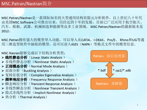
MSCPatranamp;Nastran入门讲座
被单击的所有对象
完全被矩形框包围(和与矩 形框边界相交)的对象
完全被多边形框包围(和与 多边形框边界相交)的对象
通过键盘输入数据的语法格式为:对象类型标识符 对象标号列表
对象类型
标识符
对象类型
标识符
几何点 面 实体
point/p surface
solid
节点 单元 多点约束
node/n element/ele
*.bdf 求解(Nastran)
*.op2/*.xdb
*.op2/*.xdb *.f06 *.f04 *.BDALL *.MASTER
后处理(Patran)
导入分析结果(Analysis)
生成变形图、云图、报告等(Results)
*.ses.** *.rpt
注意:Nastran分析完毕后,不要盲目将得到的结果文件(op2或xdb)读入Patran,一定要 先打开f06文件并在里面搜索fatal(致命错误),只有搜不到fatal时才可以进入下一步,否 则应根据出错信息修改模型并再次提交分析。
MPC
7
总结五:数据输入(二)
对象标号列表的格式: ➢ 多个对象标号之间用空格或逗号分隔; ➢ 有规律的对象标号用<起始标号>:<终止标号>[:步长]。 例如element 1,3 4:10:2代表标号为1,3,4,6,8,10的单元。 坐标、向量的输入格式: ➢ 坐标用方括号对([])标识,各分量之间用空格或逗号或左斜线分隔; ➢ 向量用尖括号对(<>)标识,各分量之间用空格或逗号或左斜线分隔。 例如[100 200 300],<1,0,0>。 选择菜单的使用 选择菜单(select menu)一般和矩形框选方法配合使用,通过选取选择菜单上的对象类型, 可以对选择集内的对象进行过滤,只有指定类型的对象才能被选中。 随着操作类型的不同,选择菜单的选项会发生变化。
MSC优化Patran实例PPT课件
Step 3. Create New Nodes
a
Create new nodes a. Elements b. Create/Node/Edit c. Deselect Associate with
Geometry d. Enter [-10 0 0] for Node Location
List e. Apply
b c
d
e
z
f
Step 5. Create and Define the Material’s properties
a
Define a material using the specified modulus of elasticity and allowable stresses.
a. Materials b. Create/Isotropic/Manual Input c. Enter alum for Material Name d. Input Properties… e. Enter 10e6 for Elastic Modulus = f. Enter 0.3 for Poisson Ratio = g. Enter 0.1 for Density = h. OK i. Apply
for Node 2 = f. Apply
Repeat steps a – c with: Node 2 for Node 1 = Node 4 for Node 2 = and click Apply. Repeat steps a – c with: Node 3 for Node 1 = Node 4 for Node 2 = and click Apply.
alum with area of 1. 7. Create another 1-D rod with property set named prop_2 and sets its material
Patran二次开发工具PCL系列教程之7

Output:
<Return Value> widget Item widget ID. NULL if item not created.
Comments:
Menus, menubars, and switches use itemicon widgets. The functional attributes of the item are defined by the parent widget type. The position of the item relative to other currently existing children for the parent widget is specified by the order in which the items are PAT304 Course Notes – Release 9.5 created, i.e., the item created first will appear first in the parent widget, the last item Copyright 2001 MSC.Software Corporation 7-9 created will appear last.
7-8
Item Icon
ui_itemicon_create( parent, name, iconname, toggleable )
Function:
Creates an icon item widget to be used as a child of a menu, or switch widget.
Creates a toggleicon widget.
Input:
MSC patran nastran 分析实例
9.0
Case Study: Scuba Tank
Model Simplification Methods ………………………………………… ………………………………………… 9-6 Importing Geometry ………………………………………………………………………………………………. 9-11 Viewports ………………………………………………………………………………………………………….. 9-51 Mesh Density Control ……………………………………………………………………………………………. 9-64 Axisymmetric Elements ………………………………………………………………………………………….. 9-86
MSC.Software Corporation
2 MacArthur Place Santa Ana, CA 92707, USA Tel: (714) 540-8900 Fax: (714) 784-4056 Web:
Tokyo, Japan Tel: 81-3-6911-1200 Fax: 81-3-6911-1201
4.0
Case Study: Stadium Arched Roof Truss
MSC.Nastran Element Library ………… ………………………………………………………………………... 4-5 The CROD Element ………………………………………………………………………………………………. 4-19 Post Processing CROD Results ………………………………………………………………………………… 4-48
TABLE OF CONTENTS
PATRAN_交流
LOGO
MSC/NASTRAN 主要功能
5) 多级超单元分析
线性静力超单元分析 屈曲超单元分析 动力超单元分析(模态综合法) 包括固有模态分析,直接与模态复特征值,直接与模态频率响应 和直接与模态瞬态响应。 气动弹性响应超单元分析 颤振超单元分析 稳态与瞬态热传导超单元分析 循环对称(静力、屈曲)超单元分析
LOGO
利用虚拟光驱打开PATRAN安装原文件,选择 MSC.Licensing安装
LOGO
安装license时license选择
安装过程中有next选next,’yes’ or’ no’时选yes
声响分析 流体与结构耦合分析 循环对称分析 层复合材料分析
LOGO
二.软件安装
liscence
NASTRAN
PATRAN/ NASTRAN 安装顺序
PATRAN
LOGO
1.安装liscense
更改D:\MSC_NASTRAN_V2005_R2LND\LEGEND\lisense.dat中的计算机名
LOGO
MSC.PATRAN/NASTRAN主要特点与功能
1)大型、通用、功能齐全、适用面广
2)极高的软件可靠性 3)世界领先的计算结构技术先进性 4)独特的DMAP语言
5) 标准的输入/输出格式
LOGO
MSC/NASTRAN 主要功能
1)静力分析
线性静力分析(包括惯性卸载) 屈曲分析 包括线弹性屈曲,弹性非线性屈曲和弹塑性屈曲分析。 静力几何与材料非线性分析 包括大变形(大位移、大转动以及跟随力),非线性弹性,弹塑 性,蠕变, 粘弹性以及接触问题。 正交模态分析(固有频率与振动模态) 直接复特征值分析 模态复特征值分析 直接频率响应分析 模态频率响应分析 直接瞬态响应分析 模态瞬态响应分析 响应谱分析 随机动力分析 具有几何和(或)材料非线性的瞬态响应分析
SimOffice之MSC Patran
SimOffice之MSCPatran作者:MSC.software2004年9月28日MSC.Software发布了MSC.SimOffice-V2005产品系列,该产品系列将MSC.Software传统的主线产品MSC.Nastran、MSC.Patran、MSC.ADAMS、MSC.Marc、MSC.Dytran及MSC.EASY5等整合在一起,帮助众多用户从容应对多学科、多层面、集成化、跨平台等诸多新的挑战。
MSC.Patran v2005MSC.Patran是机械CAE分析软件的开放式前后处理平台,它为工程设计、分析和分析结果评估提供完整的三维CAE环境。
MSC.Patran2005具有更加精确多样的CAD几何接口集成系统,更为完善的CAD数据组织和分组功能;高级曲面网格划分功能的进一步加强大大缩短了网格前处理的时间;与各种CAE分析软件MSC.Marc,MSC.Dytran,MSC.Nastran,以及LS-DYNA等交互式接口的进一步提高和完善使得各个领域的分析都变得更加便捷;有限元结果数据分量的合成显示等新功能的加入使Patran2005在结果处理上更易于理解。
具体功能如下:一、前处理部分1.支持HP-UX和AIX新的3GB内存的使用,对于处理超大模型更加方便;2.更好的CAD数据输入接口,根据CAD分层信息自动分组;3.直接Pro/ENGINEER接口/网格划分,Patran2005直接读入Pro/E模型,不需要做任何的几何修补直接生成网格;Patran2005在输入Pro/E文件的时候,相关的材料数据信息随同输入,从Pro/E输入的材料信息包括以下内容:材料名称(标准的PTC part参数)材料特性(标准的PTC part参数)材料参考说明(客户化扩展,使用用户自定义的参数)4.CAD输出数据接口的扩展从MSC.Patran2005开始,支持以下的通用几何输出格式:* Parasolid xmt * IGES * Patran Neutral * STEP 203 * STEP 209 * I-DEAS 10 * ACIS 13.0 * VDA * STEP 214 * CATIA V4.1.9几何实体的输出类型包括:线,面和体如果Parasolid转换文件包含特征,特征同样可以输出。
06_Hypemesh和MSC.PatranNastran软件介绍解析
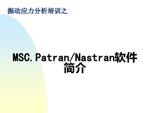
MSC.Patran用户界面风格
▲ Patran界面组成
▲▲▲ 功能菜单 ◆ 包括File, Group,Viewport,Viewing,Display,Preference,Tools,Insight Control和Utilities(缺省不出现) ◆ 只影响全局性环境或共用操作,如视角,色彩,个人偏爱等
刷新屏幕
显示设置复位
Undo,取消上一次操作(仅一次)
▲ 功能模块
▲ ▲典型的风格 ▲ ▲按钮功能
Action: 动作 Object: 对象 Method(Type): 方式 Apply(Cancel): 点Apply后,才从Form中读数据,否则输入数据 无效;
▲ ▲常用Motif工具
Select Databox 数据选择框 Toggle button 二相开关 Push button 按钮
◆按下任一个,右边出现相应Application Widget
▲▲▲ 快捷访问图符菜单
◆用户自定制的快捷图符菜单
▲▲▲ 历史窗口
◆显示操作PATRAN每一步过程。
▲▲▲ 命令行
◆命令行输入。
▲▲▲System Icon
Patran在线帮助文档资料 终止操作 调整窗口在屏幕上可见性 PATRAN运行状态 绿色 表等待用户输入 蓝色表Patran正运行,可用 红色 表Patran正运行,用 终止 无效
▲ ▲对CAD软件开放 ▲ ▲对FEM软件的开放 ▲ ▲对材料信息系统的开放
▲ 强大的布尔计算、实体建模、抽取中面、几何编辑功能 ▲ 强有力的网格生成功能 ▲ 逼真的结果可视化功能 ▲ 开放的软件开发环境
▲ ▲Patran提供编程语言—PCL语言,是用户进行专
patran,初学,入门,自学,实例1

课程 1. 入门目的:本次练习中,学习内容如下:⏹进入MSC/PATRAN并运行一个过程文件⏹对窗口和框架进行移动、调整尺寸及图标化操作⏹熟悉屏幕拾取⏹熟悉在线帮助的使用模型描述:本练习中,将学习如何进入MSC/PATRAN、生成一个MSC/PATRAN数据库及运行一个已存在的过程文件以生成一个用于这次练习的MSC/PATRAN模型。
还将练习对图形窗口和主框架进行移动、调整尺寸及图标化操作。
此外,还要学习如何使用在线帮助。
由于本次练习的重点是学习MSC/PATRAN的基本知识,因此,在练习的过程中穿插讨论了一些MSC/PATRAN的通用命令格式及操作。
练习过程:1.在X—窗口中键入patran。
此窗口中将会显示有关状态信息。
之后MSC/PATRAN主框架将出现。
Main Form如下图:最初,除File菜单外,主框架中的其它菜单都是灰色的。
通常,为利于操作,MSC/PATRAN将把不可能执行的选项设成灰色。
例如,移动鼠标光标到Main Form的File上,单击鼠标左键。
在下拉式菜单中,只出现与数据库有关的操作。
因为运行MSC/PATRAN之后的第一件事是创建或打开一个数据库。
建立一个新的数据库并命名为exereise_1.db。
File/NewNew Database Name:片刻之后,出现绘图窗口。
当建立一个新数据库时,将出现New Model Preferences对话框。
选择框中容差区的不同选项,可使MSC/PATRAN以两种不同方式区分模型中相邻的两个点。
在Tolerance中选Based on Model时,是以模型中最大尺寸的0.05%做为容差,若选Default,则以缺省值0.005作为模型的容差。
在这个练习中,选择Default选项。
在New Model Preferences对话框中,还可以选择Analysis Code 和Analysis Type,它们将影响建模期间各种对话框的内容。
MSC Patran官方案例分享

8.patran官方案例Ⅳ-热-构造运动(en).pdf
9.patran官方案例Ⅳ-赫兹接触问题(en).pdf
MSC Patran官方案例
更新时间:2014-9-2六角网格几何图形(en).pdf
2.patran官方案例Ⅰ-使用列表和多点约束(en).pdf
3.patran官方案例Ⅰ-添加一个图标到工具栏(en).pdf
4.patran官方案例Ⅰ-使用矢量扫描六面体网格生成(en).pdf 5.patran官方案例Ⅰ-添加一个图标来快速提取(en).pdf 6.patran官方案例Ⅰ-质量特性计算(en).pdf
三、patran官方案例Ⅲ
1.patran官方案例Ⅲ-创建框架表面(en).ppt
2.patran官方案例Ⅲ-表面提取实例(en).ppt
3.patran官方案例Ⅲ-附录A(en).ppt
4.patran官方案例Ⅲ-二维网格连杆(en).ppt 5.patran官方案例Ⅲ-Parasolid实体示例(en).ppt 6.patran官方案例Ⅲ-框架表面模型的分析(en).ppt
6.patran官方案例Ⅱ-Exercise_05CAD热分析(en).pdf
7.patran官方案例Ⅱ-Exercise_07烤箱窗设计(en).pdf
8.patran官方案例Ⅱ-Exercise_08温度决定材料性质(en).pdf 9.patran官方案例Ⅱ-Exercise_09混合微电路的热分析(en) .pdf 10.patran官方案例Ⅱ-Exercise_10时间决定边界条件(en).pdf
7.patran官方案例Ⅲ-活塞头分析(en).ppt
8.patran官方案例Ⅲ-锚的材料和网格属性
9.patran官方案例Ⅲ-加筋板(en).ppt
Patran_PPT教程_第1章_简介
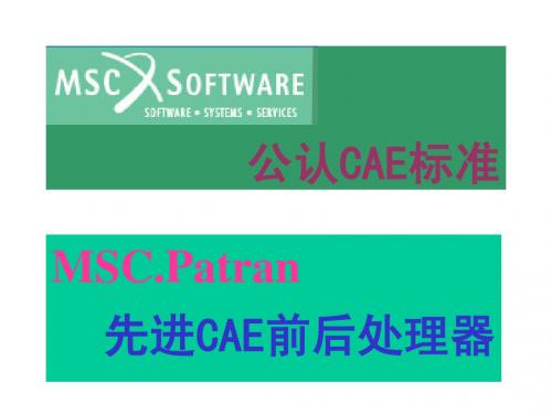
Modelname.db.jou
日志文件
记录从模型创建到目前的所有PCL命令。若数据库不慎删除,可根据日 志文件恢复。
Settings.pcl
偏好设置文件
ASCII文件。起动Patran会自动依据该文件设置Patran的环境变量。
p3epilog.pcl
ASCII文件,类似于DOS的autoexec.bat ,Patran起动时,自动执行该文 件。
作用:取消一个对象 方法:光标移到对象上,点右键
作用:循环选择 方法:按住shift,点右键
▲鼠标中键用法
▲按句法直接输入
▲ ▲几何编号
几何名称 点 关键字 Point 示 例 Point 1:24:3 Solid 55.3.1.1 线 Curve Curve 3 8 21 Surface 3.2 面 Surface Surface 1:200:2 Solid 10.2 体 向量 平面 坐标系 Solid Vector Plane Coord Solid 10:50:3 Vector 5 Plane 2 Coord 1.3 1号坐标系的z轴 意 义 1到24号点,间隔为3;即1,4, 7,10, 13,16,19,22。 55号实体第三面第一边1号顶点 3号,第8号,第21号曲线 3号面上的第2号边 1到100号面,间隔2 10号实体2号面 1到100号实体,间隔3
3. MSC.Patran用户界面风格
▲ Patran界面组成
Patran界面由Main Form ,Viewport 和Application Widget 组成 ▲ ▲ Main Form
▲▲▲ Menu Bar ◆ 包括File, Group,Viewport,Viewing,Display,Preference,Tools,Insight Control和Utilities(缺省不出现) ◆ 只影响全局性环境或共用操作,如视角,色彩,个人偏爱等 ◆ 与求解器及分析步骤无关 ▲▲▲ Application ◆由Geometry,Finite Element,Load/BCs,Materials,Properties,Fields,Load Cases,Analysis, Results,Insight和 X-Y Plot按钮组成
Patran PPT教程_第8章 单元物理(Properties)
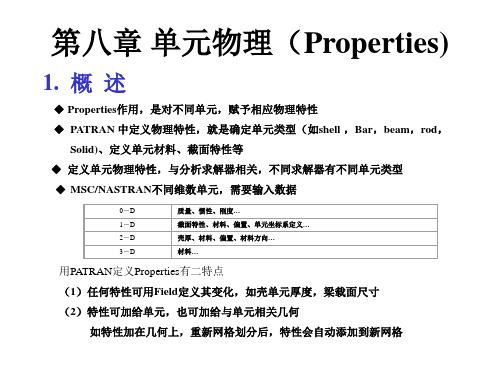
Conrod CTUBE CELAS1 CDAMP1 CVISC CGAP CGAP CMASS1 PLOTEL单元
梁单元物理特性
不同梁单元输入数据不同,以Bar单元为例,定义梁单元所须数据 • Material Name: 材料名,可从“Material Property Sets” 中选 • Bar Orientation: 梁单元坐标系,可用一矢量(Vector)或一结点号(Node)确定 • [Section Name]: 截面特性,可在“Beam Library” 中已定义截面名;或暂不给出,逐项
示例
4.板壳选取和定义
板壳分以下几类
Type Membrane Bending Panel
Shell Shear Panel
2D solid p-shell
说明 薄膜板 承弯板 壳 剪切板 2维板单元,即平面应变单元或轴对称单元 2维p单元
对板壳元(除2D solid外),定义时须输入材料及“shell thickness” 还可定义法向偏置(Offset) 板壳元物理特性定义类似梁
◆ MSC/NASTRAN不同维数单元,需要输入数据
0-D 1-D 2-D 3-D
质量、惯性、刚度… 截面特性、材料、偏置、单元坐标系定义… 壳厚、材料、偏置、材料方向… 材料…
用PATRAN定义Properties有二特点 (1)任何特性可用Field定义其变化,如壳单元厚度,梁载面尺寸 (2)特性可加给单元,也可加给与单元相关几何
界面
3. Msc/Nastran梁单元选取、定义和显示
梁单元类型和选取
Type
Beam
Rod Spring Damper Gap 1D Mass PLOTEL
基于MSC_Patran_Nastran的桥式起重机主梁优化设计
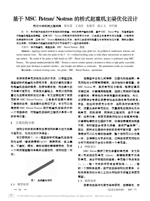
基于MSC 1P atran/N astran 的桥式起重机主梁优化设计郑州大学机械工程学院 秦东晨 王迎佳 朱晓芳 陈江义 刘竹丽 摘 要:针对现行主梁设计中存在的结构笨重、材料浪费严重的问题,基于MSC.Patran 平台,构造某型桥式起重机箱型主梁模型,应用MSC.Nastran 对其进行结构和受力分析;以主梁各板厚度为优化变量,以强度和刚度指标为约束,应用MSC.Nastran 提供的优化方法,进行以主梁结构轻量化为目标的优化计算,得到合理的优化结果。
对我国桥式起重机的现行设计方法进行了一些改进和探索。
关键词:桥式起重机;箱型主梁;MSC.Patran/Nastran ;优化Abstract :Applying current methods to design overhead traveling crane girder has the problem of cumbers ome structure and serious material waste.This takes box girder of the 5-16t overhead traveling crane as study object and presents an improved de 2sign method.The m odel of the girder is built based on MSC.Patran and structure and force analysis is performed using MSC.Nastran.The optimal method provided by MSC.Nastran is used to conduct optimal calculation to obtain as light girder as possible with girder plate thickness as optimal variables ,and strength and stiffness as constraints.The optimization results are reas onable.K eyw ords :traveling crane ;box girder ;MSC.Patran/Nastran ;optimization 采用有限单元法和优化设计方法,以某型正轨箱型梁桥式起重机为研究对象,通过计算机仿真分析起重机主梁的强度、刚度和稳定性,找出最大应力和最大变形处,然后在此基础上,完成以结构轻量化为主要目标的优化计算。
Patran二次开发工具PCL系列教程之8
= Postscript Default
Print Orientation = Portrait, Landscape; Landscape $ Note use of default
PAT304 Course Notes – Release 9.5 Copyright 2001 MSC.Software Corporation
The Start/End Toolbar Lines (NT only) define the boundaries of the dockable toolbars
PAT304 Course Notes – Release 9.5 Copyright 2001 MSC.Software Corporation
$
= 100 %
Image Size = Fit on Page, As Is Scale Factor = No Show; 1.0 Center = No Show; Yes Draw Borders $ Note use of “No Show” and a default
= Yes, No
8-7
PATRAN Toolbar Icons
*ICON specifies the icon that is to be used in the Toolbar form.
The icons are restricted to a 40x40 bitmap format (typically 28x28 for UNIX or 16x16 for NT). Icons can be created using various UNIX bitmap utilities or Paint for NT. A toolbar icon template (UNIX) is supplied with MSC.Patran and can be used to create user-defined icons. • tbblank.28.icon
MSC.Patran & Nastran入门讲座

3
总结一:Patran/Nastran结构分析流程
*.db *.ses.** *.bdf *.db.jou *.op2/*.xdb *.f06 *.f04 *.BDALL *.MASTER
前处理(Patran)
几何建模 (Geometry) 划分网格 (Elements) 施加载荷及边界 条件(Loads/BCs) 创建材料 (Material) 单元赋属性 (Properties) 创建载况(Load Case)
选择菜单的使用 选择菜单(select menu)一般和矩形框选方法配合使用,通过选取选择菜单上的对象类型, 可以对选择集内的对象进行过滤,只有指定类型的对象才能被选中。 随着操作类型的不同,选择菜单的选项会发生变化。
9
组(Group)的操作:用途及与AutoCAD图层之比较
组是合理组织模型、高效操作视图的有效工具。 简单模型无需分组,将所有对象放在默认组(Default group)中即可;而对于复杂模型, 则必须分组,且在开始建模之前就必须谋划好如何组织模型,从而决定需要建几个组、每 个组包含哪些对象。 Patran中的组在某些方面与AutoCAD中的图层(Layer)非常相似,比如: 图层有当前图层和非当前图层之分;而组也有当前组和非当前组的区别。 在AutoCAD中,新建对象自动分布在当前图层中;而在Patran中,新建对象自动包含进 当前组中。 在AutoCAD中,对象可以在图层之间移动,从而方便修改对象的各种属性;而在Patran 中,对象也可以从一个组移动/复制到另一个组。 在AutoCAD中,从属于同一个图层的对象具有相同的属性(如线型、线宽、颜色等); 而在Patran中可以为各个组的各种对象(如各种几何体和单元)分别指定显示效果。 当然,Patran中的组和AutoCAD中的图层还是有区别的,主要表现在: 在AutoCAD中,包含对象的图层是不能被删除的;而在Patran中,可以随意删除不是当 前组的组(无论组中是否包含对象),且默认情况下组所包含的对象并不会被删除。 在AutoCAD中,同一对象只能属于一个图层;而在Patran中,同一对象可以从属于多个 组。
patran拓扑优化第二章
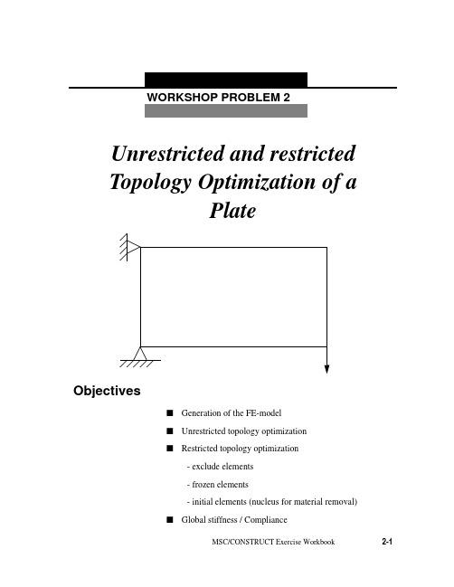
WORKSHOP PROBLEM 2Unrestricted and restrictedTopology Optimization of aPlateObjectivess Generation of the FE-models Unrestricted topology optimizations Restricted topology optimization- exclude elements- frozen elements- initial elements (nucleus for material removal)s Global stiffness / ComplianceMSC/CONSTRUCT Exercise Workbook2-12-2MSC/CONSTRUCT Exercise WorkbookWorkshop 2Topology optimization of a plateMSC/CONSTRUCT Exercise Workbook2-3Model Description:The goal of this exercise is to find the optimized topology for a plate subject to a single force with different options.Figure 2.1 below shows the geometry and boundary conditions of the plate.Figure 2.1 Geometry and boundary conditions of the plateYoung’s Modulus: 2.1 * 105 N/mm 2 Poisson Ration:0.3Length: 480mm Width: 320mm Thickness: 20mm Loading:600N480320xF=600NyIntroductionWithin MSC/CONSTRUCT various restrictions can be specified toinfluence the topology optimization process in order to meet functional orproduction requirements.E. g. you cana)- exclude elements from the optimization group(see workshop example No. 1)b)- freeze elements (frozen elements)c)- mark areas where to start the optimization (initial elements)d)- limit the maximum displacement of the structure (global stiffness)Items a) - d) shall be applied in this example but first of all an unrestrictedtopology optimization shall be carried out.2-4MSC/CONSTRUCT Exercise WorkbookWorkshop 2Topology optimization of a plateMSC/CONSTRUCT Exercise Workbook2-5Exercise Procedure:1. Unrestricted topology optimization1.1Prepare the FE-Model with MSC/PATRANIn comparison to workshop example 1 take into account the modified geometry and use 20 units as the ’’Global Edge Length ’’.Fix the nodes 1, 26, 376, 401 in x- and y- direction and "smear" the single force F = 600N over the nodes 25, 50, 75.Create the Nastran Input Deck topo_var.bdf for the optimization with MSC/PATRAN.1.2Creation of the MSC/NASTRAN Input Deck without MSC/PATRANThe generated MSC/NASTRAN input deck has to be modified for the optimization process like in workshop example No. 1 (see page 1-12)1.3Create the parameter file for the topology optimization in MSC/PATRAN1.3.1 Start the MSC/CONSTRUCT Interface in MSC/PATRAN.MSC/CONSTRUCT Action: Create Object: Parameter File Method:Topology Parameter FilesName: simpleInput Parameter...2-6MSC/CONSTRUCT Exercise Workbook1.3.2 Create the Data Input SectionLoad the FE-Model data (nodes and elements) for the optimization 1.3.3.Create the Object Definition SectionInclude all elements in the optimization group..1.3.4.Create the Optimization SectionSpecify the formula for the stress calculation --> Stress hypothesis: von Mises hypothesis Select Input File Select Input File Input Files:topo_var.bdfOK CreateGroups Group Name:DESIGN_ELEM Type:Element Select Elements:Elm 1:384Add CreateLoad Calculation Load Calc Name:LOAD_CALC_1Type:Hypo Component:MisesCreateWorkshop 2Topology optimization of a plateMSC/CONSTRUCT Exercise Workbook2-7Define the objective function --> Objective function is the relative volume Specify the optimization type and assign the design variables, an objective function and the stress hypothesis. Highlight the names in the boxes.- Specify the maximum number of iteration cycles 1.3.5 Create the Output SectionObjective Function Objective Name:OBJ_FUNC_1Type:Relative Volume Variable:None Value:0.60CreateOptimization Existing Groups:DESIGN_ELM Existing Load Calc:LOAD_CALC_1Existing Objective:OBJ_FUNC_1CreateTermination Criteria Type:Maximum Iteration Number of Iteration:30CreateOutput Request Predefined Macros:uf_topo_pat.macCreate2-8MSC/CONSTRUCT Exercise WorkbookEnd the Construct Interface and save the parameter file.The created parameter file is shown in Figure 2.2Figure 2.2 Parameter file simple.par !! INPUT FILE FOR TOPOLOGY OPTIMIZATION ! MODEL :simple ! AUTHOR :training! DATE :08-Dec-97 10:19:18! LAST CHANGE :! REMARKS :! DESCRIPTION :! - - - - -DATA INPUT SECTION READ, topo_var.bdf! - - - - -OBJECT DEFINITION SECTION SELECT, ELEM, S, ELEM, 1,384,1GROUP_DEF,ELEM, DESIGN_ELEM! - - - - -OPTIMIZATION SECTIONLOAD_CALC, LOC_DEF_1, HYPO, MISESOBJ_FUNC, USER_OBJ_FUNC_1,REL_VOL, 0.60OPTIMIZE, TOPO, DESIGN_ELEM, USER_OBJ_FUNC_1,LOC_DEF_1STOP, ITER_MAX, 30! - - - - -OUTPUT SECTION INCLUDE, uf_topo_pat.mac SA VE EXITEnd you patran session.1.4Carry out the optimizationBecause the name of the parameter file and the MSC/NASTRAN input file are not the same you have to start the optimization with the command:construct -type all -job simple -nas topo_var.bdfOK ApplyWorkshop 2Topology optimization of a plateMSC/CONSTRUCT Exercise Workbook2-91.5Postprocessing1.5.1 Material distributionFigure 2.3 Material distribution after the 14th iteration1.5.2 AnimationWithin MSC/PATRAN with the Insight tool you can create an animation of the material removal from the first to the last iteration.In order to animate the model you have to carry out the following steps:x Insight Action: Create Tool:Isosurface Isosurface Value: x ResultsResult Selection Current Load Case:select all iterationsUpdate resultsAnimation AttributesÌEnable AnimationAnimation Type:x Global VariableGlobal Variable: IterationOKIsosurface Result MP, ValueIsovalue SetupIsovalue:10000OK x Global VariableResult OptionsElement Result Mapping:x Element ConstantOKOKIsosurface AttributesÌClip at Isosurface< Display:Free Edge> Display:ShadedOKApplyFor start the animation go to in the menubar toInsight Control / Animation ControlSetup ...Animation Mode Animate Tools - 3DAnimation Tool Is-Isos_1 IterationFrames:17Animate2-10MSC/CONSTRUCT Exercise WorkbookWorkshop 2Topology optimization of a plate If you want to finish the animation click on Clear.In general: all SELECT and GROUPING operations as well as all otheroperations can be carried out with the MSC/CONSTRUCT preprozessorfor non MSC/PATRAN user. But for more complicated problems thisbecomes very tedious as one explicitly has to extract nodal and/orelement information from the finite element model.2. Restricted Topology Optimization2.1Explizit definition of the design spaceExclude two element rows from the design space which are attached to the left edge of the plate as well as these elements which are involved in the introduction of the load.Define additional the volume reduction in the first iteration and the speed for the volume reduction in the second and subsequent iteration.Modify the Object Definition Section and the Optimization Section in the existing parameter file simple.par and generate a new one, called design.par .2.1.1 Read in the existing parameter file simple.par .2.1.2 Modify the Object Definition SectionDefine the design space without the two element rows on the left edge as well as the elements which are assigned with the load ( see in the following picture, Figure 2.4)MSC/Construct Action: ReadObject:Parameter FileSelect Parameter File Parameter File Name:.../simple Apply Action: Create Object: Parameter File Method:Topology Parameter File Name:.../simple.par Input ParameterWorkshop 2Topology optimization of a plate Figure 2.4 Design Elements.GroupsGroup Name:DESIGN_ELEMType:ElementSelect Elements:Element 3:23 27:47 51:7275:96 99:120 123:144147:168 171:192 195:216219:240 243:264 267:288291:312 315:336 339:360363:384AddCreate2.1.3 Modify the Optimization Section.Define the volume reduction in the first iteration Define the speed for the volume reduction in the second and subsequent iteration.Save the parameter file under the new name design.parSolution Control Type:Start Option:Percent Value:0.1Existing Groups:DESIGN_ELEMCreateSolution Control Type:Speed Option:Moderate Existing Groups:DESIGN_ELEMCreateWorkshop 2Topology optimization of a plateFigure 2.5 Parameter file design.par! INPUT FILE FOR TOPOLOGY OPTIMIZATION! MODEL :design! AUTHOR :training! DATE :08-Dec-97 10:19:18! LAST CHANGE :! REMARKS :! DESCRIPTION :! - - - - -DATA INPUT SECTIONREAD,topo_var.bdf! - - - - OBJECT DEFINITION SECTIONSELECT, ELEM, S, ELEM, 3, 23, 1SELECT, ELEM, A, ELEM, 27, 47, 1SELECT, ELEM, A, ELEM, 51, 72, 1SELECT, ELEM, A, ELEM, 75, 96, 1SELECT, ELEM, A, ELEM, 99, 120, 1SELECT, ELEM, A, ELEM, 123, 144, 1SELECT, ELEM, A, ELEM, 147, 168, 1SELECT, ELEM, A, ELEM, 171, 192, 1SELECT, ELEM, A, ELEM, 195, 216, 1SELECT, ELEM, A, ELEM, 219, 240, 1SELECT, ELEM, A, ELEM, 243, 264, 1SELECT, ELEM, A, ELEM, 267, 288, 1SELECT, ELEM, A, ELEM, 291, 312, 1SELECT, ELEM, A, ELEM, 315, 336, 1SELECT, ELEM, A, ELEM, 339, 360, 1SELECT, ELEM, A, ELEM, 363, 384, 1! - - - -OPTIMIZA TION SECTION!LOAD_CALC, LOC_DEF_1, HYPO, MISESOBJ_FUNC, USER_REF_1,REL_VOLUM, 0.60OPTIMIZE, TOPO, DESIGN_ELEM, USER_REF_1,LOC_DEF_1CONT_TOPO, DESIGN_ELEM, START, PROZ, 0.1CONT_TOPO, DESIGN_ELEM, SPEED_TOPO, MODERA TESTOP, ITER_MAX, 30! - - - - -OUTPUT SECTIONINCLUDE,uf_topo_pat.macSA VEEXITStart the optimization and check the results.Figure 2.6 Material distribution after the 18th optimization cycleWorkshop 2Topology optimization of a plate2.2 Use frozen elementsDefines which elements are excluded from the optimization. The volume of these elements however is included in determining the objective function. (difference to the further example )2.2.1 Read in the existing parameter file simple.par .Look page 2-12 in order to read in an existing parameter file.2.2.2 Modify the Object Definition SectionDefine all elements as Design Elements Define the Frozen ElementsAll elements which were excluded from the design space in workshop example 2.1 now should be assigned to a frozen element group. Select these elements and create a group called Frozen_Elem ( Figure 2.7 )Groups Group Name:DESIGN_ELEM Type:Element Select Elements:Element 1:384Add CreateFigure 2.7 Frozen ElementsAnother possibility to create a construct group is at first to create a MSC/ PATRAN group with the neccassary elements and then to create the MSC/ CONSTRUCT group from the MSC/PATRAN group.Create the MSC/PATRAN group in the Group-Menu in PatranGroup/CreateNew Group Name:Frozen_ElemType:ElementEntity Selection:Elm 1, 2, 24, 25, 26, 48, 49, 50,73, 74, 97, 98, 121, 122, 145,146, 169, 170, 193, 194, 217,218, 241, 242, 265, 266, 289, 290313, 314, 337, 338, 361, 362ApplyWorkshop 2Topology optimization of a plateCreate the MSC/CONSTRUCT group in the Construct-Menu 2.2.3 Modify the Optimization Section.- Define which elements during the optimization may be not modified as a restrictionDefine the speed for the volume reduction in the second and subsequent iteration.Groups Type:Element Patran Groups:Frozen_ElemCreateTopology Restrictions Type:Frozen Existing Element Group:Frozen_ElemCreateSolution Control Type:Speed Option:Moderate Existing Groups:DESIGN_ELEMCreateSave the parameter file under the new name frozen.par Figure 2.8 Parameter file frozen.par! INPUT FILE FOR TOPOLOGY OPTIMIZATION! MODEL :frozen! AUTHOR :training! DATE :09-Dec-97 14:49:18! LAST CHANGE :! REMARKS :! DESCRIPTION :! - - - - -DATA INPUT SECTIONREAD, topo_var.bdf! - - - - OBJECT DEFINITION SECTIONSELECT, ELEM, S, ELEM, 1, 384, 1GROUP_DEF, ELEM, DESIGN_ELEMSELECT, ELEM, S, ELEM, 1SELECT, ELEM, A, ELEM, 2SELECT, ELEM, A, ELEM, 24, 26, 1SELECT, ELEM, A, ELEM, 48, 50, 1SELECT, ELEM, A, ELEM, 73SELECT, ELEM, A, ELEM, 74SELECT, ELEM, A, ELEM, 97SELECT, ELEM, A, ELEM, 98SELECT, ELEM, A, ELEM, 121SELECT, ELEM, A, ELEM, 122SELECT, ELEM, A, ELEM, 145SELECT, ELEM, A, ELEM, 146SELECT, ELEM, A, ELEM, 169SELECT, ELEM, A, ELEM, 170SELECT, ELEM, A, ELEM, 193SELECT, ELEM, A, ELEM, 194SELECT, ELEM, A, ELEM, 217SELECT, ELEM, A, ELEM, 218SELECT, ELEM, A, ELEM, 241SELECT, ELEM, A, ELEM, 242SELECT, ELEM, A, ELEM, 265SELECT, ELEM, A, ELEM, 266SELECT, ELEM, A, ELEM, 289SELECT, ELEM, A, ELEM, 290SELECT, ELEM, A, ELEM, 313SELECT, ELEM, A, ELEM, 314SELECT, ELEM, A, ELEM, 337SELECT, ELEM, A, ELEM, 338SELECT, ELEM, A, ELEM, 361SELECT, ELEM, A, ELEM, 362GROUP_DEF, ELEM, Frozen_Elem! - - - - -OPTIMIZATION SECTIONLOAD_CALC, LOC_DEF_1, HYPO, MISESOBJ_FUNC, USER_REF_1,REL_VOLUM, 0.60OPTIMIZE, TOPO, DESIGN_ELEM, USER_REF_1,LOC_DEF_1 CONT_TOPO, DESIGN_ELEM, SPEED_TOPO, MODERATEREST_TOPO, FROZEN_ELEM, FROZENSTOP, ITER_MAX, 30! - - - - -OUTPUT SECTIONINCLUDE, uf_topo_pat.macSA VEEXITWorkshop 2Topology optimization of a plateStart the optimization and check the resultsFigure 2.9 Material distribution after the 20th optimization cycle usingFrozen ElementsWith the same objective function (60% material removal) more materialwill be removed using frozen elements rather then excluding elementsfrom the design space ( compare Figure 2.6 with Figure 2.9). The reasonis that the volume of the frozen elements is included in the determinationof the objective function.2.3Use frozen and initial elementsBy specifying initial elements the location where material will be removed first, can be determined. This may be necassary for symmetrical loaded and constraint structures.Figure 2.10 shows the initial elements (black shaded) proposed for this example. They have to be selected and grouped first and then defined in the optimization section of the parameter file according to Figure 2.11.In addition these elements should be frozen at which boundary conditions ( forces and supports) are applied.Figure 2.10 Initial Elements2.2.1 Read in the existing parameter file simple.par.Read in the existing parameter file how it is described in page 2-122.2.2 Modify the Object Definition SectionUse the defined MSC/CONSTRUCT group Design_Elem from the readed parameter fileWorkshop 2Topology optimization of a plateDefine the Initial ElementsInclude as Initial Elements these elements which are in the upper edge (see Figure 2.11).Define the Frozen ElementsInclude as Frozen Elements these elements which are applied with the load and the boundary conditions.2.2.3 Modify the Optimization Section.- Define which elements during the optimization may be not modified as a restrictionGroups Group Name:Initial_Elem Type:ElementSelect Elements:Element 264:360:24 380:384Add CreateGroups Group Name:Frozen_Elem Type:Element Select Elements:Elm 1 24 48 361Add CreateTopology Restrictions Type:Frozen Existing Element Group:Frozen_ElemCreate- Define the initial restiction Save the parameter file under the new name initial.par according Figure 2.12, carry out the optimization and compare the material distribution after 17th iteration with Figure 2.13.Figure 2.12 Parameter file with initial elements! INPUT FILE FOR TOPOLOGY OPTIMIZATION ! MODEL :initila ! AUTHOR :training! DATE :15-Dec-97 10:19:18! LAST CHANGE :! REMARKS :! DESCRIPTION :! - - - - -DATA INPUT SECTION READ, topo_var.bdf! - - - - OBJECT DEFINITION SECTION SEL, ELEM, S,1,384,1GROUP_DEF,ELEM, DESIGN_ELEM SELECT, ELEM, S, 380SELECT, ELEM, A, 381SELECT, ELEM, A, 382SELECT, ELEM, A, 383SELECT, ELEM, A, 384SELECT, ELEM, A, 288SELECT, ELEM, A, 312SELECT, ELEM, A, 336SELECT, ELEM, A, 360GROUP_DEF, ELEM, Initial-Elem SELECT, ELEM, S, 1SELECT, ELEM, A, 361SELECT, ELEM, A, 24SELECT, ELEM, A, 48GROUP_DEF, ELEM, Frozen_Elem! -- - - -OPTIMIZATION SECTIONLOAD_CALC, LOC_DEF_1, HYPO, MISESOBJ_FUNC, USER_OBJ_FUNC_FUNC_1, REL_VOLUM, 0.50OPTIMIZE, TOPO, DESIGN_ELEM, USER_REF_1,LOC_DEF_1REST_TOPO, Initial_Elem, INITIAL, LINE REST_TOPO, Froezen_Elem, FROZEN STOP, ITER_MAX, 30! - - - - -OUTPUT SECTION INCLUDE.uf_topo_pat.mac SA VE EXITTopology Restrictions Type:Initial Option:Line Existing Element Group:Initial_ElemCreateWorkshop 2Topology optimization of a plate Figure 2.13 Material distribution after 17th iteration3. Global stiffness / ComplianceThe global stiffness is declared as the objective function when the maximum allowed displacement of the structure is specified.Within MSC/CONSTRUCT a maximum allowable displacement could be defined in the objective function. This displacement value is based on the maximum total displacement calculated in the first FE-analysis. The material distribution will be determined based on this results. In addition other restrictions can be used like frozen or initial elements.Besides the discussed definitions for the parameter file (element selection etc.) variables have to defined and assigned3.1Define the variables in the Object Definition Section.3.1.1 Read in the existing parameter file simple.par.Read in the existing parameter file simple.par how it is described in page2-123.1.2 Modify the Object Definition SectionDefine all elements as Design Elements except the element on which theload and boundary condition are applied.GroupsGroup Name:DESIGN_ELEMType:ElementSelect Elements:Element 2:23 25:4749:360 362:384CreateCreateWorkshop 2Topology optimization of a plateNodes are necassary for the determination of the displacement. Thats why a group has to be created which includes all nodes..q Define the maximum allowed displacement- Assign a variable to the maximum displacement value of the first FE-analysis named TAR_STIFF1- Assign a variable to the maximum allowed displacement value for the optimization named TAR_STIFF2Groups Group Name:DISP_NODES Type:Nodes Select Elements:Node 1:425Create CreateNumerical Variable Variable Name:Tar_Stiff_1Type:BASE Value:DISP_ABS Option:MAX Existing Group:DISP_NODESCreateNumerical Variable Variable Name:Tar_Stiff_2Type:FIX Value: 1.15Create- Multiply both variables and named the result TAR_STIFF33.2Define the Optimization SectionDefine the objective function 2.1.3 Modify the Optimization Section.Define the speed for the volume reduction in the second and subsequent iteration.Numerical Variable Variable Name:Tar_Stiff_3Type:OPER Value:MULT Variable:Tar_Stiff_1Variable:Tar_Stiff_2CreateObjective Function Objective Name:OBJ_FUNC_1Type:Stiffness Variable:FIRST Existing Variables:Tar_Stiff_3Existing Variables:Tar_Stiff_1CreateSolution Control Type:Speed Option:Moderate Existing Groups:DESIGN_ELEMCreateWorkshop 2Topology optimization of a plateSpecify the tolerance file accordingly.Save the parameter file under the new name stiffness.par and check the results with Figure 2.15Figure 2.14 Parameter file stiffness.par! INPUT FILE FOR TOPOLOGY OPTIMIZATION ! MODEL :stiffness ! AUTHOR :training! DATE :16-Dec-97 17:17:09! LAST CHANGE :! REMARKS :! DESCRIPTION :! - - - - -DATA INPUT SECTION READ, topo_var.bdf! - - - - OBJECT DEFINITION SECTION SELECT, ELEM, S, ELEM, 264, 360, 24SELECT, ELEM, A, ELEM, 380, 384, 1GROUP_DEF, ELEM, DESIGN_ELEM SELECT, NODE, S, NODE, 1, 425, 1GROUP_DEF, NODE, DISP_NODES! - - - - -OPTIMIZATION SECTIONLOAD_CALC, LOC_DEF_1, HYPO, MISESVARIABLE,TAR_STIFF1,BASE,DISP_ABS,MAX,DISP_NODES VARIABLE,TAR_STIFF2,FIX,1.15VARIABLE,TAR_STIFF3,OPER,MULT,TAR_STIFF1,TAR_STIFF2OBJ_FUNC, USER_REF_1,STIFFNESS,TAR_STIFF3,FIRST,TAR_STIFF1OPTIMIZE, TOPO, DESIGN_ELEM, USER_REF_1,LOC_DEF_1CONT_TOPO, DESIGN_ELEM, SPEED_TOPO, MODERATE CONT_TOPO, DESIGN_ELEM, EPSILON, PROZ, 0.05 STOP, ITER_MAX, 30! - - - - -OUTPUT SECTION INCLUDE,uf_topo_pat.mac SA VE EXITSolution Control Type:Epsilon Option:Percent Value:0.05Existing Groups:DESIGN_ELEMCreateFigure 2.15 Material distribution after the 14th iteration。
Patran教程工况及边界条件PPT课件
● 在Lood/BCs中,将Action中设成”Plot Marker”
① 在Assigned Load/BCs Sets下滚动窗中选要显示边界条件名
② 在Select Group滚动窗中选某些“组”名
③ 点动Apply。
第4页/共9页
Show Tabular
第5页/共9页
Plot Contours
也可从Spatial Fields窗中选取已定义的Field 如是Time Dependent Load Case, 出现Non-Spatial Fields窗,选Field定义的时间历程
输入矢量说明 (8) 点Select Application Region, 选作用域 (9) 点Apply
示例
以云纹图形式显示标量边界条件信息 如: Y方向上载荷,正压力,温度等在受载面或线上分布
第6页/共9页
第7页/共9页
5.修改、删除Load/BCs(Delete & Modify) 6. 工况(Load Case)
工况是对载荷和约束的分类和组合 可先建很多LBC,然后通过Create或Modify工况将其放到不同工况中 也可先建工况,然后在Load/BCs时,直接把边界条件添加到相应工况中 边界条件很简单,所有边界条件自动添加到Default工况中
Default Load Case是静态载荷工况
第1页ቤተ መጻሕፍቲ ባይዱ共9页
2. 载荷边界条件类型
Patran主要载荷边界条件(MSC/NASTRAN为例)
类型 Displacement Force Pressure Temperature
Inertial Load Initial Displacement
Initial Velocity Distributed Load Contact
Patran_Sec09_载荷.ppt

练习
通用机械: 完成练习册中 Workshop 12 “Anchor Loads and Boundary Conditions Using a Field”
CID分布的载荷
Total load 总载荷
Inflow
来流
Outflow
出流
Contact
接触
Temperature 温度
Heat source 热源
Heat flux(热通量)
Convection 对流
Radiation
辐射
Also, view factor(视角因子)
结构分析中的载荷和边界条件 选择模板
显示 载荷和边界条件
云纹图显示载荷边界条件:
温度 矢量分量
目标矢量必须从Select Data Variable 栏中 选择 矢量必须先创建标量才能云纹显示 可应用于当前视窗中的所有组 为了将应用于几何上的 Loads/BCs set显示 在有限元上, 首先, 在Display/Load/BC/El中 激活 “Show on FEM Only”, 然后在 Loads/BCs 窗口中使用 Plot Markers 命令
坐标系 3 是柱坐标
热载荷 & 边界条件
所显示的是MSC.Patran Thermal支持的载荷和 边界条件集合
对流传热举例
T=300K
Aluminum Plate
1 m h=(1.5*y)+10 (W/m2 K)
q=3000 W/m2 1m
Tambient=300 K
Y
Y
300.0 300.0 300.0 300.0 300.0 300.0 300.0 300.0 300.0 300.0 300.0
patran例子
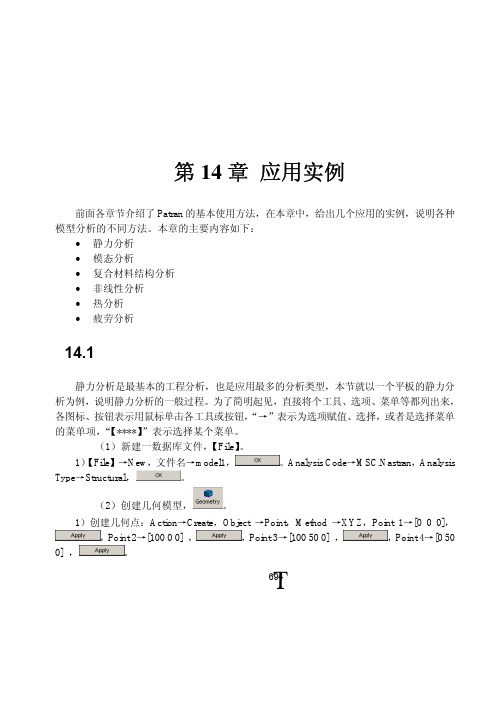
Element,Number→10,Auto Execute,Curve List→surface 1.2,Curve List→surface 1.4;Number
→5,Curve List→surface 1.1,Curve List→surface 1.3。
2)划分网格:Action→Create,Object→Mesh,Type→Surface,Elem Shape→Quad,Mesher
,Force<F1 F2 F3>→<10 0 0>,Moment<M1 M2 M3>→<0 0 0>,
,
,FEM,Select Nodes→Node 11:66:11,
,
,
,即在板的一边施加 X 向的单向拉伸载荷。
施加了边界条件的平板如图 14-3 所示。
Τ696
图 14-3 给平板模型施加边界条件
List→point 3,Ending Point List→point 4,
。
3)创建曲面:Action→Create,Object→Surface,Method→Curve,Option→2 Curve,Auto
Execute,Surface 1,Starting Curve List→Curve 1,Ending Curve List→Curve 2。
,
。此时,
Patran 会将模型提交 Nastran 运算,会弹出一个 DOS 形式的窗口,显示 Nastran 的运行情况,
运算完成之后,计算机的扬声器会有提示音,同时,状态显示窗口关闭。
2)读入分析结果:Action→Read Output2,Object→Result Entities,Method→Translate,
- 1、下载文档前请自行甄别文档内容的完整性,平台不提供额外的编辑、内容补充、找答案等附加服务。
- 2、"仅部分预览"的文档,不可在线预览部分如存在完整性等问题,可反馈申请退款(可完整预览的文档不适用该条件!)。
- 3、如文档侵犯您的权益,请联系客服反馈,我们会尽快为您处理(人工客服工作时间:9:00-18:30)。
properties.. 14. Create design variables using 1-D rod with prop_1 and prop_2 and associated areas. 15. Create design objective from the design study pre-processing tools. 16. Create design constraints on X displacement, Y displacement, and axial stress.
Suggested Exercise Steps
17. Create a design study called opt_1 by including design variables, objectives and constraints.
18. Review the design study contents using the Design Study Summary option. 19. Create an input file for optimization – Set necessary parameters. 20. Select the existing design study and global objective. 21. Create the subcases by including desired constraints. Select subcase for the job.
alum with area of 1. 7. Create another 1-D rod with property set named prop_2 and sets its material
property to alum with area of 2. 8. Under Loads/BCs, create a new nodal displacement called disp_1 and sets its
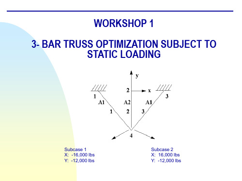
WORKSHOP 1
3- BAR TRUSS OPTIMIZATION SUBJECT T16,000 lbs Y: -12,000 lbs
Subcase 2 X: 16,000 lbs Y: -12,000 lbs
Design Model Description
X direction 0.2 in Y direction 0.2 in
Suggested Exercise Steps
1. Open a new database and call it wkshp1.db. 2. Turn on all the labels and select front view. 3. Create new nodes for the model. 4. Create bar elements from the previous nodes 5. Make a new material called alum and sets its properties. 6. Create a 1-D rod with property set named prop_1 and sets its material property to
Generate the analysis Bulk Data file: wkshp1.bdf 22. Compare wkshp1.bdf with the sample input file. 23. Compare wkshp1.bdf with the sample input file (cont'd). 24. Compare wkshp1.bdf with the sample intput file (cont'd). 25. Submit the wkshp1.bdf for Nastran analysis and check for errors. 26. Compare the results with the sample output. 27. In Patran, read the result file using Nastran's generated file, wkshp1.op2. 28. Plot the Design Variable History on the XY plot. 29. Plot the Objective Function History on the XY plot. 30. Plot the Maximum Constraint History on the XY plot. 31. Quit MSC.Patran.
Objective Function: Weight minimization
Design Variables: Cross-sectional area A1 and A2
Constraints: Stress Allowable:
Displacement at grid 4:
20 ksi tension 15 ksi compression
region. 11. Create another force called force_2 and sets its force properties and application
region. 12. Create a load case called case_1 and sets its properties. 13. Create another load case called case_2 and sets its displacement and force
