K03_HMI_FSU
中达优控PLC触摸屏一体机说明书及详细参数
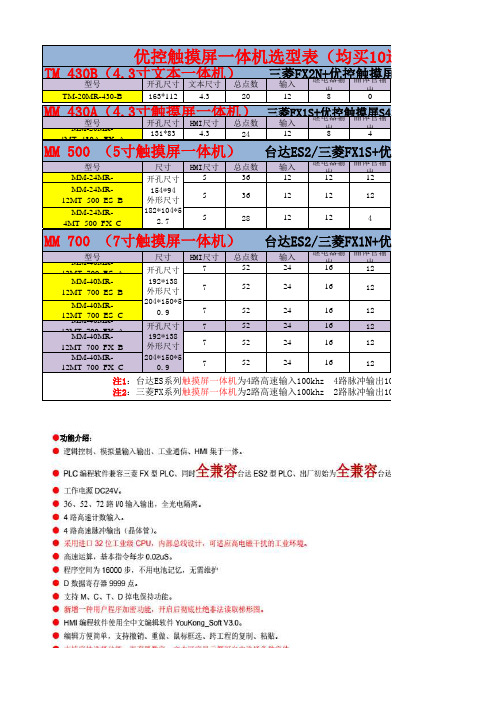
TM
430B(4.3寸文本一体机)
型号
开孔尺寸 文本尺寸 总点数
三输菱入FX2继N电+出器优输控晶触体出摸管输屏MD430
TM-20MR-430-B
163*112
4.3
20
12
8
0
MM
430A(4.3寸触摸屏一体机)
MM型-2号0MR-
开孔尺寸 HMI尺寸 总点数
0
0
无 三菱FX1S 398元/台
FX1S+优控触摸屏S500A
温度
AD
0
0
2 路 10K NTC
(-50℃至+150
2
℃)
2 路 K 型热电 偶
2
DA
485通信 PLC软件 价格
0
1路 台达ES2 450元/台
2
无
台达ES2 468元/台
2
无 三菱FX1S 498元/台
FX1N+优控触摸屏S700A
24 24 24
16 16 16
ቤተ መጻሕፍቲ ባይዱ
12 12 12
MM-40MR12MT_700_FX_C
204*150*5 0.9
7
52
24
16
12
注1:台达ES系列触摸屏一体机为4路高速输入100khz 4路脉冲输出100khz 继电器输出最大负载 注2:三菱FX系列触摸屏一体机为2路高速输入100khz 2路脉冲输出100khz 继电器输出最大负载
温度
AD
DA
485通信 PLC软件
0
0
2 路 10K NTC
(-50℃至+150
ref615内部故障人机界面模块代码2
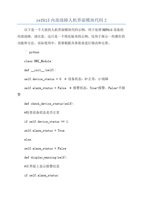
ref615内部故障人机界面模块代码2以下是一个大致的人机界面模块代码示例,用于处理REF615设备的内部故障。
请注意,这只是一个简化版本的示例,仅用于展示一些潜在的功能和方法。
实际使用中,需要根据具体需求进行修改和完善。
```pythonclass HMI_Module:def __init__(self):self.device_status = 0 # 设备状态:0-正常,1-故障self.alarm_status = False # 报警状态:True-报警,False-不报警def check_device_status(self):#检查设备状态是否正常if self.device_status == 1:self.alarm_status = Trueelse:self.alarm_status = Falsedef display_warning(self):#在界面上显示报警信息if self.alarm_status:print("Warning: Internal Fault Detected!")else:print("No alarm!")def handle_user_input(self):#监听用户输入并处理while True:choice = input("Enter your choice (1-Fi某 fault, 0-E某it): ")if choice == "1":self.fi某_fault。
breakelif choice == "0":breakelse:print("Invalid choice, please try again.")def fi某_fault(self):#修复故障print("Fi某ing internal fault...")self.device_status = 0print("Internal fault fi某ed!")def run(self):#界面运行主循环while True:self.check_device_status。
Kinco-HMI问答集锦
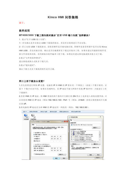
Kinco HMI问答集锦源于:软件应用MT4000/5000下载工程失败时提示“打开USB端口失败”怎样解决?1. 提示“打开USB端口失败”:1)首先确认是否安装过USB下载线的驱动,若没有安装则进行手动安装;2)若已安装USB下载线驱动,请检查硬件是否被电脑识别,即硬件设备管理器中是否出现Kinco HMI USB。
若没有被识别,确认是否往触摸屏里下载过旧版本工程,如果有建议用最新的软件更新文件系统和内核,再用新版本软件编译工程下载。
如果没有建议换电脑或换其他方式下载。
2.提示“文件校验和错误”:建议换线或换台式机多下载几次。
3.提示“通讯超时”:确认下载方式及下载线的制作是否正确。
网口上传下载怎么设置?1.首先需要进行网络IP设置,电脑的IP和HMI的IP要在同一个网段上(前面三个数字相同,后面1 个数字应该不同;如果在局域网内,其IP地址不能与网络中其他IP相冲突)才能进行上传下载操作。
2.查看HMI的IP地址。
将HMI背面的两个拨码开关都打到ON然后上电即进入系统设置界面,可以查看到HMI的IP地址(例如:192.168.0.100)Port 号(例如:21845)查看后要把拨码开关都打到off。
3.将电脑的IP地址改为和HMI的IP地址同一网段的(例如:192.168.0.90)。
1)HMI上电,用网线将电脑和HMI连接起来。
2)打开组态编辑软件,工具à下载方式选择à通讯方式选择网口,IP 和port号填写第二步查看的HMI的IP地址(例如:192.168.0.100)Port 号(例如:21845)点击确定,网络IP通讯参数就设置好了。
然后点击工具菜单栏à下载(或者上传工程)即可。
如何打开上传上来的工程?1.首先确认上传上来的工程文件格式是否PKG(只有PKG格式才能反编译打开);2.打开组态编辑软件,工具菜单栏下à反编译(最下面)进入KH Manager 反编译处理界面;3.在反编译操作里点击选择找到需要反编译的PKG文件,然后选择反编译后生成的目标工程文件保存路径(不选择的话就是默认路径);4.点击反编译进行操作,会弹出密码输入框要求输入密码。
郎汉德 PLC 触摸屏一体机(4.3 寸) 产品说明书

郎汉德PLC触摸屏一体机(4.3寸)产品说明书文件版本:V1.0.0目录1.产品简介 (3)2.参数详情 (3)2.1.电气参数 (3)2.2.PLC编程电缆参数 (4)2.3.选型表 (6)2.4.拨码状态 (7)2.5.接线图 (8)2.5.1.晶体管输出型号引脚定义 (8)2.5.2.继电器输出型号引脚定义 (10)2.6.PLC地址 (11)2.6.1.PLC地址使用情况 (11)2.6.2.特殊寄存器和位 (12)2.7.模拟量转换 (16)2.8.兼容三菱指令 (17)3.通信使用 (21)3.1.串口通信配置 (21)3.2.一体机内部PLC与HMI通讯(COM2) (22)3.2.1.使用FX3U协议内部通讯 (22)3.2.2.使用Modbus RTU内部通讯 (25)3.3.串口通信发送与接收数据的应用(COM4) (27)3.3.1.PLC做为Modbus从站通信 (27)3.3.2.串口自由通信协议ADPRW指令使用 (28)3.3.3.Modbus主站通信协议ADPRW指令使用 (31)4.售后 (33)4.1.联系方式 (33)4.2.免责声明 (33)1.产品简介本产品为PLC触摸屏一体机。
PLC支持3U编程风格;HMI组态图库丰富。
2.参数详情2.1.电气参数类别项目参数电气环境供电电源额定24V,12-32V宽压输入范围;内部与外供电电气隔离工作温度0~55°C湿度5%-95%RH(非结露)抗干扰性峰值:1500vp-p;幅度1uS;上升时间:30ms;周期30-100HZ抗震动符合IEC61121-2标准电气隔离性能通讯隔离性通讯口均与内部隔离电源隔离性内部5V、15V之间隔离;与24V输入隔离数字量量输入导通状态高于DC15V,2.5mA 关断状态低于DC7V,1mA晶体管输出响应时间ON->OFF20us以内OFF->ON50us以内输出电压范围DC5V~30V额定输出负载0.75A@DC24V继电器输出响应时间10ms以内输出电压范围DC5V-30或AC5V~250V 额定输出电压DC24V/2A或AC220V/2.0A 使用寿命机械1千万次电气10万次(额定负载)模拟量输出输出范围电压输出0~10V 电流输出0~20mA模拟量输入输入范围电流输入0-20mA或4-20mA电压输入0-10V运动控制脉冲输出速度可达200KHZ 计数输入速度可200K以上2.2.PLC编程电缆参数一体机的PLC部分,对应的编程口为RS232通信。
Moxa UC-8200系列Arm Cortex-A7双核心1GHz IIoT闸门说明书

UC-8200系列Arm Cortex-A7雙核心1GHz IIoT閘道,內建LTE Cat.4,1個用於Wi-Fi模組的迷你PCIe擴充插槽,1個CAN連接埠、4個DI、4個DO特色與優點•Armv7Cortex-A7雙核心1GHz•Moxa工業Linux,提供10年超長期間支援•LTE規格電腦,獲得Verizon/AT&T認證以及工業級CE/FCC/UL認證•雙SIM插槽•2個自動感應10/100/1000Mbps乙太網路連接埠•整合式LTE Cat.4模組,支援US/EU/APAC頻帶•1個CAN連接埠,可支援CAN2.0A/B•具有microSD插槽,可擴充儲存空間•配備可程控LED以及可程控按鈕,讓您輕鬆地完成安裝與維護•-40至85°C寬溫範圍設計,啟用LTE時溫度範圍為-40至70°C認證簡介UC-8200運算平台是專為嵌入式資料擷取應用所設計。
電腦配備兩個RS-232/422/485串列埠、雙10/100/1000Mbps乙太網路連接埠、一個CAN連接埠,以及雙Mini PCIe插槽以支援Wi-Fi/行動通訊網路模組。
這些多元功能讓使用者能有效地調整UC-8200以適應各種複雜通訊解決方案。
UC-8200採用的是專為能源監視系統進行最佳化的Cortex-A7雙核心處理器,但是該處理器目前已被廣泛地用於各種工業解決方案。
這款輕薄的嵌入式電腦是可靠且安全的閘道,具備彈性的介面選項,可協助您在現場進行資料擷取並進行處理,同時也是適用於許多其他大規模部署的實用通訊平台。
已啟用LTE的寬溫度型號可用於延伸的溫度應用。
所有裝置全都在試驗室中經過完整測試,保證已啟用LTE的運算平台適用於寬溫應用。
外觀UC-8210UC-8220規格ComputerCPU Armv7Cortex-A7dual-core1GHzDRAM2GB DDR3LStorage Pre-installed8GB eMMCPre-installed OS Moxa Industrial Linux(Debian9,Kernel4.4)See /MILExpansion Slots MicroSD(SD3.0)socket x1Computer InterfaceTPM UC-8210-T-LX-S:TPM v2.0UC-8220-T-LX-AP-S:TPM v2.0UC-8220-T-LX-EU-S:TPM v2.0UC-8220-T-LX-US-S:TPM v2.0Ethernet Ports Auto-sensing10/100/1000Mbps ports(RJ45connector)x2 Serial Ports RS-232/422/485ports x2,software selectable(DB9male) CAN Ports CAN2.0A/B x1(DB9male)Digital Input DIs x4Digital Output DOs x4USB2.0USB2.0hosts x1,type-A connectorsWi-Fi Antenna Connector RP-SMA x2(UC-8220only)Cellular Antenna Connector SMA x2(UC-8220only)GPS Antenna Connector SMA x1(UC-8220only)Expansion Slots mPCIe slot x2(UC-8220-T-LX)mPCIe slot x1(UC-8220-T-LX US/EU/AP models)SIM Format Nano(UC-8220only)Number of SIMs2(UC-8220only)Buttons Programmable buttonEthernet InterfaceMagnetic Isolation Protection 1.5kV(built-in)Serial InterfaceConsole Port1x4-pin header to DB9console portBaudrate300bps to921.6kbpsData Bits5,6,7,8Parity None,Even,Odd,Space,MarkStop Bits1,1.5,2Serial SignalsRS-232TxD,RxD,RTS,CTS,DTR,DSR,DCD,GNDRS-422Tx+,Tx-,Rx+,Rx-,GNDRS-485-2w Data+,Data-,GNDRS-485-4w Tx+,Tx-,Rx+,Rx-,GNDCAN InterfaceNo.of Ports1Connector DB9maleBaudrate10to1000kbpsIndustrial Protocols CAN2.0A,CAN2.0BIsolation2kV(built-in)Signals CAN_H,CAN_L,CAN_GND,CAN_SHLD,CAN_V+,GNDDigital InputsConnector Screw-fastened Euroblock terminalDry Contact Off:openOn:short to GNDIsolation3K VDCSensor Type Wet contact(NPN)Dry contactWet Contact(DI to COM)On:10to30VDCOff:0to3VDCDigital OutputsConnector Screw-fastened Euroblock terminalCurrent Rating200mA per channelI/O Type SinkVoltage24VDC nominal,open collector to30VDCCellular InterfaceCellular Standards LTE CAT-4Band Options US model:LTE Bands:Band2(1900MHz)/Band4(1700MHz)/Band5(850MHz)/Band13(700MHz)/Band14(700MHz)UMTS Bands:Band2(1900MHz)/Band5(850MHz)Carrier Approval:Verizon,AT&TEU model:LTE Bands:Band1(2100MHz)/Band3(1800MHz)/Band5(850MHz)/Band7(2600MHz)/Band8(900MHz)/LTE Band20(800MHz)UMTS Bands:Band1(2100MHz)/Band2(1900MHz)/Band5(850MHz)/Band8(900MHz)AP model:LTE Bands:Band1(2100MHz)/Band3(1800MHz)/Band5(850MHz)/Band7(2600MHz)/Band8(900MHz)/Band28(700MHz)UMTS Bands:Band1(2100MHz)/Band2(1900MHz)/Band5(850MHz)/Band8(900MHz)GPS InterfaceReceiver Types72-channel u-blox M8engineGPS/GLONASS/GalileoAccuracy Position:2.5m CEPSBAS:2.0m CEPAcquisition Aided starts:3secCold starts:26secSensitivity Cold starts:-148dBmTracking:-164dBmTime Pulse0.25Hz to10MHzLED IndicatorsSystem Power x2Programmable x1SIM card indicator x1Wireless Signal Strength Cellular/Wi-Fi x6Power ParametersNo.of Power Inputs Redundant dual inputsInput Voltage12to48VDCPower Consumption10WInput Current0.8A@12VDCReliabilityAlert Tools External RTC(real-time clock)Automatic Reboot Trigger External WDT(watchdog timer)Physical CharacteristicsDimensions141.5x120x39mm(5.7x4.72x1.54in)for UC-8220141.5x120x27mm(5.7x4.72x1.06in)for UC-8210Housing SECCMetalInstallation DIN-rail mounting,Wall mounting(with optional kit)IP Rating IP30Weight UC-8210:560g(1.23lb)UC-8220:750g(1.65lb)Environmental LimitsAmbient Relative Humidity5to95%(non-condensing)Operating Temperature UC-8210-T-LX:-40to85°C(-40to185°F)UC-8210-T-LX-S:-40to85°C(-40to185°F)UC-8220-T-LX:-40to70°C(-40to158°F)UC-8220-T-LX-US-S:-40to70°C(-40to158°F)UC-8220-T-LX-EU-S:-40to70°C(-40to158°F)UC-8220-T-LX-AP-S:-40to70°C(-40to158°F)Storage Temperature(package included)-40to85°C(-40to185°F)Shock IEC60068-2-27Vibration2Grms@IEC60068-2-64,random wave,5-500Hz,1hr per axis(without USB devicesattached)Standards and CertificationsSafety UL62368-1,EN62368-1EMC EN55032/35,EN61000-6-2/-6-4EMI CISPR32,FCC Part15B Class AEMS IEC61000-4-2ESD:Contact:4kV;Air:8kVIEC61000-4-3RS:80MHz to1GHz:10V/mIEC61000-4-4EFT:Power:2kV;Signal:1kVIEC61000-4-6CS:10VIEC61000-4-8PFMFIEC61000-4-5Surge:Power:0.5kV;Signal:1kVHazardous Locations Class I Division2,ATEXCarrier Approvals VerizonAT&TGreen Product RoHS,CRoHS,WEEEMTBFTime UC-8210-T-LX:716,739hrsUC-8210-T-LX-S:708,581hrsUC-8220-T-LX:650,836hrsUC-8220-T-LX-US-S:528,574hrsUC-8220-T-LX-EU-S:528,574hrsUC-8220-T-LX-AP-S:528,574hrsStandards Telcordia(Bellcore)Standard TR/SRWarrantyWarranty Period5yearsDetails See /tw/warrantyPackage ContentsDevice1x UC-8200Series computerDocumentation1x quick installation guide1x warranty cardInstallation Kit1x DIN-rail kit(preinstalled)1x power jack6x M2.5mounting screws for the cellular module Cable1x console cable尺寸UC-8210UC-8220訂購資訊Model Name CPU RAM Storage TPM mPCIe Slot1forLTE ModulemPCIe Slot2forWi-Fi ModuleOperatingTemperatureUC-8210-T-LX1GHz Dual Core2GB8GB–––-40to85°C UC-8210-T-LX-S1GHz Dual Core2GB8GB Built-in––-40to85°C UC-8220-T-LX1GHz Dual Core2GB8GB–Reserved Reserved-40to70°CUC-8220-T-LX-US-S 1GHz Dual Core2GB8GB Built-inUS region LTEmodulepreinstalledReserved-40to70°CUC-8220-T-LX-EU-S 1GHz Dual Core2GB8GB Built-inEurope regionLTE modulepreinstalledReserved-40to70°CUC-8220-T-LX-AP-S 1GHz Dual Core2GB8GB Built-inAPAC region LTEmodulepreinstalledReserved-40to70°C配件(選購)Power AdaptersPWR-12150-EU-SA-T Locking barrel plug,12VDC,1.5A,100to240VAC,Continental Europe(EU)plug,-40to75°C operatingtemperaturePWR-12150-UK-SA-T Locking barrel plug,12VDC,1.5A,100to240VAC,United Kingdom(UK)plug,-40to75°C operatingtemperaturePWR-12150-USJP-SA-T Locking barrel plug,12VDC1.5A,100to240VAC,United States/Japan(US/JP)plug,-40to75°Coperating temperaturePWR-12150-AU-SA-T Locking barrel plug,12VDC,1.5A,100to240VAC,Australia(AU)plug,-40to75°C operatingtemperaturePWR-12150-CN-SA-T Locking barrel plug,12VDC,1.5A,100to240VAC,China(CN)plug,-40to75°C operating temperaturePower WiringCBL-PJTB-10Non-locking barrel plug to bare-wire cableCablesCBL-F9DPF1x4-BK-100Console cable with4-pin connector,1mWi-Fi Wireless ModulesUC-8200WiFi-AC Wi-Fi package for UC-8200,includes Wi-Fi module,6screws,1heat sink,1padAntennasANT-LTEUS-ASM-01GSM/GPRS/EDGE/UMTS/HSPA/LTE,omni-directional rubber duck antenna,1dBiANT-LTE-ASM-04BK704-960/1710-2620MHz,LTE omni-directional stick antenna,4.5dBiANT-LTE-OSM-03-3m BK700-2700MHz,multi-band antenna,specifically designed for2G,3G,and4G applications,3m cable ANT-LTE-ASM-05BK704-960/1710-2620MHz,LTE stick antenna,5dBiANT-LTE-OSM-06-3m BK MIMO Multiband antenna with screw-fastened mounting option for700-2700/2400-2500/5150-5850MHzfrequenciesANT-WDB-ARM-0202 2.4/5GHz,panel antenna,2/2dBi,RP-SMA(male)DIN-Rail Mounting KitsUC-8210DIN-rail Mounting Kit DIN-rail mounting kit for UC-8210with4M3screwsUC-8220DIN-rail Mounting Kit DIN-rail mounting kit for UC-8220with4M3screwsWall-Mounting KitsUC-8200Wall-mounting Kit Wall-mounting kit for UC-8200with4M3screws©Moxa Inc.版權所有.2021年8月04日更新。
FSU0设备安装调试SOP_V51

FSU0设备安装调试SOP_V51FSU2.0设备安装调试SOP V1.51目录1 硬件安装 (4)1.1 安装主设备SCC800-B1。
(4)1.2 安装蓄电池检测线缆 (7)1.3 安装烟雾传感器。
(10)1.4 安装水浸传感器。
(12)1.5 安装数字温度传感器。
(13)1.6 安装红外传感器。
(17)1.7 安装IP摄像头 (20)1.7.1 IP摄像机调测 (22)1.8 连接开关电源 (43)1.9 连接空调或者热交换 (44)1.10 连接智能电表 (44)1.11 连接上网模块和GPS (46)1.12 安装灯控开关 (49)2 软件升级 (53)2.1 配置笔记本电脑的IP地址和IE安全设置。
(53)2.2 登陆WebUI界面升级三个软件包 (56)2.3 配置第三方设备接入端口 (59)3 设备调试指南 (63)3.1 添加FSU编码 (63)3.2 添加设备编码。
(63)3.3 设置IP摄像头FTP使能 (64)3.4 设置NetEco服务器地址并记录SN号 (65)3.5 设置红外传感器告警模式(市内站) (67)3.6 设置温湿度参数 (67)3.7 上线验证 (68)3.8 故障导出方法 (69)4 设备测试交维指南 (71)说明:测试之前,一定要确认站点在线,否则测试告警无法上传。
(71)4.1 交流输入XX停电告警和电池供电告警测试 (71)4.2 防雷器故障告警测试 (72)4.3 整流模块XX故障告警测试 (72)4.4 开关电源浮充电压设定值测试 (73)4.5 水浸告警测试 (74)4.6 烟雾告警测试 (74)4.7 红外告警测试 (75)4.8 温湿度传感器上传数据 (75)4.9 开关电源上传数据 (76)4.10 热交换或者空调数据上传 (77)4.11 GPS数据检查 (77)4.12 电池组数据检查 (78)1 硬件安装1.1 安装主设备SCC800-B1。
金恭-HMI43-4.3寸一体机用户手册说明书

标准4.3寸一体机用户手册(**-HMI43)日期版本修改描述作者审核2020/10/14V1.0.1发布版Terence Peter使用须知本手册是编写**系列一体机中PLC可编程控制器的规格,安装以及布线等硬件的内容和安全使用注意事项。
有关一体机其他说明,如软件使用说明,请参照其他使用手册。
商标Windows,Excel是美国微软公司在美国以及其他国家的注册商标。
其他公司名称或产品名称是这些公司的商标或注册商标。
在安装、运行、维护、检查可编程控制器之前,请务必熟读该使用说明书以及相关的所有附带资料,正确使用。
请在熟悉了所有设备的相关知识、安全信息,以及注意事项后使用。
在该说明书中,用【危险】和【注意】对安全注意事项进行等级区分。
此外,即使是【注意】中记载的事项,因具体情况不同,也可能带来严重的后果。
由于记载的都是重要的内容,所以务必遵守。
此外,请妥善保管好产品中附带的使用说明书,以便需要时可以取出阅读,并且必须将其交至最终使用者手中。
1.设计方面的注意事项【危险】●请在可编程控制器的外部设置安全回路,以便即使出现外部电源异常,可编程控制器故障等情况时,也能确保整个系统在安全状态下运行。
误动作、误输出有可能导致事故发生。
(1)请务必在可编程控制器的外部,构筑紧急停止回路,保护回路,防止正反转等相反动作同时进行的互锁回路、防止机械破损的定位上下限互锁回路等。
(2)当可编程控制器CPU 通过看门狗定时器出错等的自诊断功能检测出异常时,所有的输出变为OFF。
此外,当发生了可编程控制器CPU 不能检测出输入输出控制部分的异常时,输出控制有时候会失效。
此时,为了确保机械在安全的状态下运行,请对外部回路以及结构进行设计。
(3)传感器用供给电源的输出电流,因机型以及扩展模块的有无而不同。
发生过载时,除了电压自动下降、可编程控制器的输入不动作以外,所有的输出也都变为OFF,此时,为了确保机械在安全的状态下运行,请对外部回路以及结构进行设计。
HMI指令
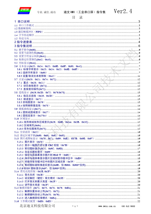
专业.诚信.成功迪文 HMI(工业串口屏)指令集Ver2.4目 录1 串口说明...............................................................................................................................31.1 串口工作模式 ...................................................................................................................................................................3 1.2 数据帧架构 ........................................................................................................................................................................3 1.3 通信帧缓冲区(FIFO)....................................................................................................................................................3 1.4 字节传送顺序 ...................................................................................................................................................................3 1.5 传送方向 ...........................................................................................................................................................................32 指令速查表 ............................................................................................................................ 4 3 指令集说明 ............................................................................................................................ 63.1 握手指令(0x00).................................................................................................................................................................6 3.2 设置当前调色板(0x40).....................................................................................................................................................6 3.3 设置字符显示间距(0x41).................................................................................................................................................6 3.4 取指定位置颜色(0x42,0x43).........................................................................................................................................6 3.5 光标显示(0x44).................................................................................................................................................................7 3.6 文本显示(0x53,0x54,0x55,0x6E,0x6F,0x98,0x45).........................................................................................7 3.6.1 标准字库显示(0x53,0x54,0x55,0x6E,0x6F) ............................................................................................7 3.6.2 选择字库显示(0x98) .............................................................................................................................................7 3.6.3 设置/取消文本框限制(0x45) ..............................................................................................................................11 3.7 点显示(0x50,0x51,0x74,0x72)...............................................................................................................................12 3.7.1 置点(0x50,0x51) ..............................................................................................................................................12 3.7.2 动态曲线显示 (0x74)..............................................................................................................................................12 3.7.3 直接显存操作(0x72)................................................................................................................................................12 3.8 连线显示 (0x56, 0x5D,0x75,0x76,0x78) .................................................................................................................13 3.8.1 指定点连线(0x56,0x5D) .................................................................................................................................13 3.8.2 频谱显示(0x75) ..................................................................................................................................................13 3.8.3 折线图显示(0x76) ...............................................................................................................................................13 3.8.4 按照偏移量连线(0x78) .......................................................................................................................................14 3.9 圆弧曲线显示(0x57).......................................................................................................................................................14 3.9.1 圆弧或圆域显示(0x57) .......................................................................................................................................14 3.9.2 圆弧段显示(0x5704) ...........................................................................................................................................14 3.10 区域显示 .......................................................................................................................................................................15 3.10.1 矩形框或矩形区域显示(0x59,0x69,0x5A,0x5B,0x5C).............................................................................15 3.10.2 区域填充(0x64) ......................................................................................................................................................15 3.10.3 双色位图填充(0x73)...............................................................................................................................................15 3.11 全屏清屏(0x52) .......................................................................................................................................................16 3.12 指定区域平移(0x60,0x61,0x62,0x63) .................................................................................................................16 3.13 图片或图标显示(0x70,0x71,0x99,0xE2,0X7B,0x9E,0x97)..................................................................16 3.13.1 图片显示(0x70) ................................................................................................................................................16 3.13.2 显示一幅图片并计算 CRC 校验(0x7B)..........................................................................................................16 3.13.3 剪切图标显示(0x71、0x9C、0x9D) ....................................................................................................................17 3.13.4 自定义图标显示(0x99) ....................................................................................................................................18 3.13.5 保存当前屏幕显示图片到 HMI 中(0xE2) ......................................................................................................18 3.13.6 保存当前屏幕显示图片区域到暂存缓冲区中(0xE9) ....................................................................................18 3.13.7 把保存暂存缓冲区中的图片区域还原(0x7F) ................................................................................................19 3.13.8 剪切图标旋转角度后显示(0x9E,仅 H600、K600+支持).................................................................................19 3.13.9 ICON 图标显示(0x97,仅 K600+支持)................................................................................................................19 3.14 背光亮度控制(0x5E, 0x5F).....................................................................................................................................20 3.14.1 背光关闭(0x5E)................................................................................................................................................20 3.14.2 设定触控(键控)背光模式(0x5E) ................................................................................................................20 3.14.3 打开背光到最大亮度(0x5F) ............................................................................................................................20 3.14.4 调节背光亮度(0x5F) ........................................................................................................................................20 3.15 触摸屏操作 (0x72,0x73,0x78,0x79,0xE4)........................................................................................................21 3.15.1 触摸位置自动上传(0x72,0x73)..........................................................................................................................21 3.15.2 触摸键码自动上传(0x78,0x79)..........................................................................................................................21 3.15.3 进入触摸屏校准模式(0xE4)...............................................................................................................................21 3.16 工作模式配置(0xE0、0xE3)...................................................................................................................................22北京迪文科技有限公司- 1 -400 018 9008专业.诚信.成功迪文 HMI(工业串口屏)指令集Ver2.43.17 指令定时循环执行(0x9A).......................................................................................................................................23 3.17.1 开启指令定时循环执行功能 ................................................................................................................................23 3.17.2 关闭指令定时循环执行功能 ................................................................................................................................23 3.18 暂存缓冲区操作(0xC0,0xC1,0xC2)........................................................................................................................23 3.18.1 写暂存缓冲区(0xC0)........................................................................................................................................23 3.18.2 读取暂存缓冲区内容(0xC2)............................................................................................................................23 3.18.3 使用暂存缓冲区数据置点(0xC101)................................................................................................................23 3.18.4 使用暂存缓冲区数据连线(0xC102)................................................................................................................23 3.18.5 使用暂存缓冲区数据显示折线图(0xC103)....................................................................................................23 3.18.6 使用暂存缓冲区数据高速显示折线图(0xC104) ............................................................................................23 3.18.7 使用暂存缓冲区数据缩放显示折线图(0xC105) ............................................................................................25 3.18.8 使用暂存缓冲区数据缩放显示窗口限制双向折线图(0xC106) ....................................................................25 3.18.9 使用暂存缓冲区作为置点缓冲区(0xC107)....................................................................................................25 3.18.10 使用暂存缓冲区来显示多参数(0xC108)......................................................................................................26 3.18.11 使用暂存缓冲区来缓冲指令实现同步显示(0xC110) ..................................................................................27 3.19 键盘操作(0x71,0xE5) ................................................................................................................................................27 3.19.1 键码上传(0x71) ................................................................................................................................................27 3.19.2 键码设置(0xE5) .....................................................................................................................................................27 3.20 用户存储器读写(0x90,0x91)................................................................................................................................28 3.20.1 写随机数据存储器(0x90 64KB)......................................................................................................................28 3.20.2 写顺序数据存储器(0x90 30MB) .....................................................................................................................28 3.20.3 读数据存储器(0x91) ........................................................................................................................................28 3.21 字库或配置文件下载(0xF2) ...................................................................................................................................28 3.22 简单算法支持(0xB0)...............................................................................................................................................28 3.22.1 拼音输入法(0xB001、0xB004) .......................................................................................................................28 3.22.2 MAC 计算(0xB002) ..........................................................................................................................................28 3.22.3 数组排序(0xB003)............................................................................................................................................28 3.23 蜂鸣器控制(0x79) ....................................................................................................................................................28 3.24 时钟(RTC)显示和读取(0x9B,0xE7) ................................................................................................................29 3.24.1 关闭时钟显示 ........................................................................................................................................................29 3.24.2 打开时钟显示 ........................................................................................................................................................29 3.24.3 时钟调整 ................................................................................................................................................................29 3.24.4 读取当前时钟(公历) ........................................................................................................................................29 3.24.5 读取当前时钟(农历) ........................................................................................................................................29 3.25 音乐播放(0x30,0x32,0x33,需要硬件支持)....................................................................................................30 3.25.1 播放指定位置的音乐(0x30) ............................................................................................................................30 3.25.2 音量调节(0x32) .................................................................................................................................................30 3.25.3 停止播放(0x33) .................................................................................................................................................30 3.26 配置文件的使用(触控界面,键控界面,动画,图标库)....................................................................................31 3.26.1 触控界面自动切换(0x1E、0x1A 配置文件).........................................................................................................31 3.26.2 键控界面自动切换(0x1B 配置文件) .....................................................................................................................33 3.26.3 自动循环执行指令组(0x1C 配置文件) ..............................................................................................................33 3.26.4 图标显示(0x1D 配置文件) ..................................................................................................................................33 3.27 HMI 和视频功能的切换(0x7A,需要硬件支持) ...................................................................................................35 3.28 强制刷新 1 次全屏显示(0xD0)...............................................................................................................................35 3.29 使用触摸屏输入参数或文本(0x7C,仅 H600、K600+支持) ..............................................................................36 3.29.1 输入纯 ASCII 字符串(0x7C01) ........................................................................................................................36 3.29.2 输入中英文混合字符串(0x7C02).....................................................................................................................37 3.29.3 强制退出输入法状态(0x7C00).........................................................................................................................374 HMI 软件升级方法............................................................................................................... 38 5 SD 卡接口下载说明............................................................................................................. 39 6 C51 串口通信程序参考........................................................................................................ 40 7 修订记录............................................................................................................................. 41北京迪文科技有限公司- 2 -400 018 9008专业.诚信.成功迪文 HMI(工业串口屏)指令集Ver2.41 串口说明1.1 串口工作模式迪文科技所有标准HMI产品均采用异步、全双工串口(UART) ,串口模式为8n1,即每个数据传送采用 10个位:1个起始位,8个数据位(低位在前传送,LSB) ,1个停止位。
空调控制器FSU调试宝典精选文档

空调控制器F S U调试宝典精选文档TTMS system office room 【TTMS16H-TTMS2A-TTMS8Q8-FSU调试:高新兴注:现场FSU软件版本需要升级到才可以支持接入。
一、调试电脑IP地址设置FSU设备初始默认IP地址为,所以使用电脑连接到FSU的网页网管,必须先配置电脑的网络也是网段的IP地址,设置电脑网段方法如下:打开“本地连接”?“属性”?“Internet 协议版本4(TCP/IP4)”?“属性”,在“Internet 协议版本4(TCP/IP4)”页面选择“使用下面的IP地址”,参照下图,根据现场网络情况配置好网络参数即可。
二、登录DAM-2160I网页网管配置好电脑与DAM-2160I设备在同一网段之后,使用IE9及以下版本浏览器(或使用IE内核的浏览器),同时浏览器必须使用兼容模式登陆设备。
注:其他版本浏览器,可能存在一些显示和排版的问题,不美观但不影响功能使用。
点击浏览器工具菜单下的兼容视图设置选项,弹出兼容视图设置如下对话框,把设备对应的IP添加进去,如下图所示:在浏览器中输入DAM-2160I-T设备的IP地址()后,登录设备会弹出一个登录界面,如下图所示:用户名:gosuncn1(可以是gosuncn1到gosuncn9),即可以允许9个用户同时登录网页网管,密码:gs2015确认非智能空调控制器对接设备com口情况一般非智能空调控制器通信接口都为485,所以现场请选择空余的485串口(com1-com6)接入。
网页配置:由于非智能控制器的协议为铁塔集团统一规范,所以在厂家上面并没有限定用哪一个厂家的产品,名称用高新兴命名,配置流程如下账号:gosuncn1密码:gs20151、在网页网管里面打开对应物理串口接线的com口假设非智能空调控制器接入我司设备com3,在配置数据的时候,打开FSU设备信息-串口接入设备类型-修改对应的com口串口类型为“智能设备采集模块”2、选择协议(需要在对应串口配置协议信息)完成1步骤后,打开FSU设备信息-串口采集配置选择对应设备串口号:例如串口3当页面读取到串口3时候,在设备1中配置如下图所示的设备类型选择:普通空调设备厂家选择:高新兴设备型号选择:TietaKT设备编码填写:需要根据具体站点确认编码配置时候请非智能空调控制器厂家留意自己设备的波特率和地址位,默认页面配置为波特率9600,地址位为1。
深圳为胜智控技术有限公司触摸屏一体机产品使用说明书

触摸屏一体机产品使用说明书--V1.6适用于以下型号:4.3寸7寸WS4312R WS7020RWS4312T WS7020TWS4320R WS7040RWS4320T WS7040TWS4322R WS7048RWS4322T WS7048T产品目录第一章产品概述 (1)1.1产品概述 (1)1.2基本参数 (1)1.3外形尺寸及安装方法.............................2-3第二章产品展示 (4)2.1产品主要硬件说明 (4)2.2产品效果图 (5)第三章触摸屏参数及编程说明 (6)3.1触摸屏基本参数 (6)3.2触摸屏编程说明 (7)3.3触摸屏与PLC通讯说明 (7)第四章PLC电气设计参考 (8)4.1电源及功耗 (8)4.2232通讯口说明 (8)4.3485通讯口说明...................................8-94.4与变频或仪表通信 (10)4.5模拟量输入输出说明............................10-114.6时钟模块说明 (12)4.7PID运算指令说明 (12)4.8高速计数 (12)4.9高速脉冲输出与脉宽调制 (13)4.10中断说明 (13)4.11产品接线图 (14)第五章PLC编程参考 (15)5.1应用环境 (15)5.2软元件功能概要 (15)5.3基本指令 (16)5.4应用指令......................................16-195.5此版本不支持指令列表 (19)第六章常见问题及解决方案 (20)第七章保修条款 (20)第一章产品概述1.1产品概述触摸屏部分:·采用32-bit240MHz ARM9CPU,运算速度快。
·高清LCD屏,26万真彩显示;·4线工业电阻触摸屏(表面硬度4H);·支持U盘下载;·使用为胜HMIStudio软件编程。
莫悟 UC-8200 系列双核麒麟A7 1GHz IIoT 网关说明书

UC-8200SeriesArm Cortex-A7dual-core1GHz IIoT gateways with built-in LTE Cat.4,1mini PCIe expansion slot for a Wi-Fi module,1CAN port,4DIs,4DOsFeatures and Benefits•Armv7Cortex-A7dual-core1GHz•Moxa Industrial Linux with10-year superior long-term support•LTE-ready computer with Verizon/AT&T certification and industrial-grade CE/FCC/UL certifications•Dual-SIM slots•2auto-sensing10/100/1000Mbps Ethernet ports•Integrated LTE Cat.4module with US/EU/APAC band support•1CAN port supports CAN2.0A/B•microSD socket for storage expansion•Programmable LEDs and a programmable button for easy installation andmaintenance•-40to85°C wide temperature range and-40to70°C with LTE enabledCertificationsIntroductionThe UC-8200computing platform is designed for embedded data acquisition applications.The computer comes with dual RS-232/422/485serial ports,dual10/100/1000Mbps Ethernet ports,and one CAN port as well as dual Mini PCIe socket to support Wi-Fi/cellular modules.These versatile capabilities let users efficiently adapt the UC-8200to a variety of complex communications solutions.The UC-8200is built around a Cortex-A7dual core processor that has been optimized for use in energy monitoring systems,but is widely applicable to a variety of industrial solutions.With flexible interfacing options,this tiny embedded computer is a reliable and secure gateway for data acquisition and processing at field sites as well as a useful communications platform for many other large-scale deployments.Wide temperature LTE-enabled models are available for extended temperature applications.All units are thoroughly tested in a testing chamber, guaranteeing that the LTE-enabled computing platforms are suitable for wide-temperature applications.AppearanceUC-8210UC-8220SpecificationsComputerCPU Armv7Cortex-A7dual-core1GHzDRAM2GB DDR3LStorage Pre-installed8GB eMMCPre-installed OS Moxa Industrial Linux(Debian9,Kernel4.4)See /MILExpansion Slots MicroSD(SD3.0)socket x1Computer InterfaceTPM UC-8210-T-LX-S:TPM v2.0UC-8220-T-LX-AP-S:TPM v2.0UC-8220-T-LX-EU-S:TPM v2.0UC-8220-T-LX-US-S:TPM v2.0Ethernet Ports Auto-sensing10/100/1000Mbps ports(RJ45connector)x2 Serial Ports RS-232/422/485ports x2,software selectable(DB9male) CAN Ports CAN2.0A/B x1(DB9male)Digital Input DIs x4Digital Output DOs x4USB2.0USB2.0hosts x1,type-A connectorsWi-Fi Antenna Connector RP-SMA x2(UC-8220only)Cellular Antenna Connector SMA x2(UC-8220only)GPS Antenna Connector SMA x1(UC-8220only)Expansion Slots mPCIe slot x2(UC-8220-T-LX)mPCIe slot x1(UC-8220-T-LX US/EU/AP models)SIM Format Nano(UC-8220only)Number of SIMs2(UC-8220only)Buttons Programmable buttonEthernet InterfaceMagnetic Isolation Protection 1.5kV(built-in)Serial InterfaceConsole Port1x4-pin header to DB9console portData Bits5,6,7,8Parity None,Even,Odd,Space,MarkStop Bits1,1.5,2Serial SignalsRS-232TxD,RxD,RTS,CTS,DTR,DSR,DCD,GNDRS-422Tx+,Tx-,Rx+,Rx-,GNDRS-485-2w Data+,Data-,GNDRS-485-4w Tx+,Tx-,Rx+,Rx-,GNDCAN InterfaceNo.of Ports1Connector DB9maleBaudrate10to1000kbpsIndustrial Protocols CAN2.0A,CAN2.0BIsolation2kV(built-in)Signals CAN_H,CAN_L,CAN_GND,CAN_SHLD,CAN_V+,GNDDigital InputsConnector Screw-fastened Euroblock terminalDry Contact Off:openOn:short to GNDIsolation3K VDCSensor Type Wet contact(NPN)Dry contactWet Contact(DI to COM)On:10to30VDCOff:0to3VDCDigital OutputsConnector Screw-fastened Euroblock terminalCurrent Rating200mA per channelI/O Type SinkVoltage24VDC nominal,open collector to30VDCCellular InterfaceCellular Standards LTE CAT-4Band Options US model:LTE Bands:Band2(1900MHz)/Band4(1700MHz)/Band5(850MHz)/Band13(700MHz)/Band14(700MHz)UMTS Bands:Band2(1900MHz)/Band5(850MHz)Carrier Approval:Verizon,AT&TEU model:LTE Bands:Band1(2100MHz)/Band3(1800MHz)/Band5(850MHz)/Band7(2600MHz)/Band8(900MHz)/LTE Band20(800MHz)UMTS Bands:Band1(2100MHz)/Band2(1900MHz)/Band5(850MHz)/Band8(900MHz)AP model:LTE Bands:Band1(2100MHz)/Band3(1800MHz)/Band5(850MHz)/Band7(2600MHz)/Band8(900MHz)/Band28(700MHz)UMTS Bands:Band1(2100MHz)/Band2(1900MHz)/Band5(850MHz)/Band8(900MHz)GPS InterfaceReceiver Types72-channel u-blox M8engineGPS/GLONASS/GalileoAccuracy Position:2.5m CEPSBAS:2.0m CEPAcquisition Aided starts:3secCold starts:26secSensitivity Cold starts:-148dBmTracking:-164dBmTime Pulse0.25Hz to10MHzLED IndicatorsSystem Power x2Programmable x1SIM card indicator x1Wireless Signal Strength Cellular/Wi-Fi x6Power ParametersNo.of Power Inputs Redundant dual inputsInput Voltage12to48VDCPower Consumption10WInput Current0.8A@12VDCReliabilityAlert Tools External RTC(real-time clock)Automatic Reboot Trigger External WDT(watchdog timer)Physical CharacteristicsDimensions141.5x120x39mm(5.7x4.72x1.54in)for UC-8220141.5x120x27mm(5.7x4.72x1.06in)for UC-8210Housing SECCMetalInstallation DIN-rail mounting,Wall mounting(with optional kit)IP Rating IP30Weight UC-8210:560g(1.23lb)UC-8220:750g(1.65lb)Environmental LimitsAmbient Relative Humidity5to95%(non-condensing)Operating Temperature UC-8210-T-LX:-40to85°C(-40to185°F)UC-8210-T-LX-S:-40to85°C(-40to185°F)UC-8220-T-LX:-40to70°C(-40to158°F)UC-8220-T-LX-US-S:-40to70°C(-40to158°F)UC-8220-T-LX-EU-S:-40to70°C(-40to158°F)UC-8220-T-LX-AP-S:-40to70°C(-40to158°F)Storage Temperature(package included)-40to85°C(-40to185°F)Shock IEC60068-2-27Vibration2Grms@IEC60068-2-64,random wave,5-500Hz,1hr per axis(without USB devicesattached)Standards and CertificationsSafety UL62368-1,EN62368-1EMC EN55032/35,EN61000-6-2/-6-4EMI CISPR32,FCC Part15B Class AEMS IEC61000-4-2ESD:Contact:4kV;Air:8kVIEC61000-4-3RS:80MHz to1GHz:10V/mIEC61000-4-4EFT:Power:2kV;Signal:1kVIEC61000-4-6CS:10VIEC61000-4-8PFMFIEC61000-4-5Surge:Power:0.5kV;Signal:1kVHazardous Locations Class I Division2,ATEXCarrier Approvals VerizonAT&TGreen Product RoHS,CRoHS,WEEEMTBFTime UC-8210-T-LX:716,739hrsUC-8210-T-LX-S:708,581hrsUC-8220-T-LX:650,836hrsUC-8220-T-LX-US-S:528,574hrsUC-8220-T-LX-EU-S:528,574hrsUC-8220-T-LX-AP-S:528,574hrsStandards Telcordia(Bellcore)Standard TR/SRWarrantyWarranty Period5yearsDetails See /warrantyPackage ContentsDevice1x UC-8200Series computerDocumentation1x quick installation guide1x warranty cardInstallation Kit1x DIN-rail kit(preinstalled)1x power jack6x M2.5mounting screws for the cellular module Cable1x console cableDimensionsUC-8210UC-8220Ordering InformationModel Name CPU RAM Storage TPM mPCIe Slot1forLTE ModulemPCIe Slot2forWi-Fi ModuleOperatingTemperatureUC-8210-T-LX1GHz Dual Core2GB8GB–––-40to85°C UC-8210-T-LX-S1GHz Dual Core2GB8GB Built-in––-40to85°C UC-8220-T-LX1GHz Dual Core2GB8GB–Reserved Reserved-40to70°CUC-8220-T-LX-US-S 1GHz Dual Core2GB8GB Built-inUS region LTEmodulepreinstalledReserved-40to70°CUC-8220-T-LX-EU-S 1GHz Dual Core2GB8GB Built-inEurope regionLTE modulepreinstalledReserved-40to70°CUC-8220-T-LX-AP-S 1GHz Dual Core2GB8GB Built-inAPAC region LTEmodulepreinstalledReserved-40to70°CAccessories(sold separately)Power AdaptersPWR-12150-EU-SA-T Locking barrel plug,12VDC,1.5A,100to240VAC,Continental Europe(EU)plug,-40to75°Coperating temperaturePWR-12150-UK-SA-T Locking barrel plug,12VDC,1.5A,100to240VAC,United Kingdom(UK)plug,-40to75°C operatingtemperaturePWR-12150-USJP-SA-T Locking barrel plug,12VDC1.5A,100to240VAC,United States/Japan(US/JP)plug,-40to75°Coperating temperaturePWR-12150-AU-SA-T Locking barrel plug,12VDC,1.5A,100to240VAC,Australia(AU)plug,-40to75°C operatingtemperaturePWR-12150-CN-SA-T Locking barrel plug,12VDC,1.5A,100to240VAC,China(CN)plug,-40to75°C operatingtemperaturePower WiringCBL-PJTB-10Non-locking barrel plug to bare-wire cableCablesCBL-F9DPF1x4-BK-100Console cable with4-pin connector,1mWi-Fi Wireless ModulesUC-8200WiFi-AC Wi-Fi package for UC-8200,includes Wi-Fi module,6screws,1heat sink,1padAntennasANT-LTEUS-ASM-01GSM/GPRS/EDGE/UMTS/HSPA/LTE,omni-directional rubber duck antenna,1dBiANT-LTE-ASM-04BK704-960/1710-2620MHz,LTE omni-directional stick antenna,4.5dBiANT-LTE-OSM-03-3m BK700-2700MHz,multi-band antenna,specifically designed for2G,3G,and4G applications,3m cable ANT-LTE-ASM-05BK704-960/1710-2620MHz,LTE stick antenna,5dBiANT-LTE-OSM-06-3m BK MIMO Multiband antenna with screw-fastened mounting option for700-2700/2400-2500/5150-5850MHzfrequenciesANT-WDB-ARM-0202 2.4/5GHz,panel antenna,2/2dBi,RP-SMA(male)DIN-Rail Mounting KitsUC-8220DIN-rail Mounting Kit DIN-rail mounting kit for UC-8220with4M3screwsWall-Mounting KitsUC-8200Wall-mounting Kit Wall-mounting kit for UC-8200with4M3screws©Moxa Inc.All rights reserved.Updated Jun29,2021.This document and any portion thereof may not be reproduced or used in any manner whatsoever without the express written permission of Moxa Inc.Product specifications subject to change without notice.Visit our website for the most up-to-date product information.。
MT8102iE iEU MT8103iE系列HMI安装和启动指南说明书

Installation and Startup GuideThis document covers the installation of MT8102iE/iEU/MT8103iE Series HMI, for the detailedspecifications and operation, please refer to Datasheet, Brochure and EasyBuilder Pro User Manual. Please read all warnings, precautions, and instructions on the device carefully before use.Install Environment: NEMA Rating The HMI product is NEMA 4 rated (Indoor Only).Electrical EnvironmentThe HMI product has been tested to conform to European CE requirements. This means that the circuitry is designed to resist the effects of electrical noise. This does not guarantee noise immunity in severe cases. Proper wire routing and grounding will insure proper operation.Environmental Considerations(1) Make sure that the displays are installed correctly and that the operatinglimits are followed. Avoid installing units in environments where severe mechanical vibration or shocks are present.(2) Do not operate the unit in areas subject to explosion hazards due toflammable gases, vapors or dusts.(3) Do not install the unit where acid gas, such as SO2 exists.(4) This device should be mounted in the vertical position and for use on the flatsurface enclosure.(5) Conform to UL 61010-2-201 safety requirement for use in Pollution Degree2 Environment.(6) Relative Humidity: 10% ~ 90% (non-condensing)CleaningConsiderationsDisconnect this device from AC outlet before cleaning. Clean the device using cloths wetted with clean water. Do not use liquid or spray detergents for cleaning.Unpacking the UnitUnpack and check the delivery. If damage is found, please contact the supplier.NOTE: Place the operator panel on a stable surface during installation. Dropping it or letting it fall may cause damage. The package includes:(1) Installation Instruction, 2-sided A4 *1 (2) Human Machine Interface *1 (3) Power Connector *1(4) Brackets & Screws *1 pack (5) Fuse 1.25A/250V 5*20mm *1 (6) USB Stick Clamp & Tying Strap *1Installation InstructionsUse a control box that provides enough stiffness. Cutout Dimension: 260 mm x 202 mm. Secure the operator panel in position, using all the fastening holes and the provided brackets and screws. Screw Torque: 2.6 ~ 3.9 lbf.in. (For reaching waterproof effect and preventing the panel from being deformed.)Plan for adequate space around the unit and inside the enclosure, for ventilation and cables. Consider the heat from other devices inside the enclosure. The ambient temperature around the unit must be 0 ~ 50°CMinimum required clearances (along the overlay): Top 15 mm / Bottom 50 mm / Sides 15 mm Maximum panel thickness: 4.5 mmUSB Stick Clamp UsageCombining the USB Stick with the clamp and the tying strap can prevent USB stick from disconnecting with HMI when strong vibration is present.1. Insert the USB connector to the clamp and tie them together with the tying strap.2. Press the spring and insert the USB stick into HMI.Power ConnectionsPower Connector Specifications: Wire AWG: 28~12Operating Temperature: -40°C ~105°C Screw Torque: 3.47 lbf-in (max.)NOTE:1. Co nnect positive DC line to the ‘+’ terminal and the DC ground to the ‘-’ terminal.2. When downloading project using a USB cable, do not connect HMI with PLC and PC simultaneously , for electric potential difference may result in damage to HMI or PC.System SettingsMT8102iE/iEUWhen HMI is powered up and displays image, click the system setting button. (Default System Password: 111111)Note: It is necessary to connect the HMI to your network through a RJ-45 cable. Go to the Network tab, you may choose to auto get DHCP IP , or designate your own IP .MT8103iEThe settings are almost the same as MT8102iE/iEU. MT8103iE supports Wi-Fi. To use Wi-Fi, go to Wireless tab, tap Wi-Fi setting button to open the settings dialog box, in which you can turn Wi-Fi on/off, choose a network, and see the signal strength of each access point.MT8102iE MT8102iEU MT8103iE series Installation Instruction3 54 1 2EasyBuilder Pro Software SettingsLaunch EasyBuilder Pro software, select your project file, press F7 shortcut key to open the downloaddialog box: Select Ethernet > IP tab > Enter your HMI IP > Click Download to download this projectfile to HMI. Using screensaver and backlight saver is recommended in order to avoid imagepersistence caused by displaying the same image on HMI for a long time.( Please refer to EasyBuilder Pro User Manual for software operation details. )Communication ConnectionsNOTE:1. COM1 /COM2 / COM3 RS485 2W support MPI 187.5K, please use one at a time.2. Only Tx & Rx (no RTS/CTS) may be used for COM1 RS232 when COM3 RS232 is also used.3. COM3 RS485 4W will not be available when COM1 RS485 2W is used.Con.B Con.ACOM1 / COM2 / COM3 [RS485] 9 Pin, Female, D-subJumper SettingsBattery ReplacementBattery replacement shall be performed by qualified personnel only and care must be taken whenhandling lithium batteries. For more information on battery replacement and disposal considerations,please refer to the following link:/download/MT8000/eng/FAQ/FAQ_103_Replace_Battery_en.pdfNOTE: Make sure that all local and national electrical standards are met wheninstalling the unit. Contact your local authorities to determine which codes apply.PowerUse power output that meets SELV (Safety Extra-Low Voltage) requirements. The unit can bepowered by DC power only, voltage range: 24±20%, compatible with most controller DCsystems. The power conditioning circuitry inside the unit is accomplished by a switching powersupply. The peak starting current can be as high as 2A.Fusing Require-mentsFuse min. rating: 1.25A/250V. Use the fuse only in DC circuit. If the display does not come onwithin 5 seconds of power up, remove power. An internal fuse will prevent damage if the polarityof the DC power is incorrect. Check wiring for proper connections and try to power up again.Replacing fuse shall be performed by qualified personnel only. For more information, see:/download/MT8000/eng/FAQ/FAQ_104_Replace_Fuse_en.pdfHigh VoltageAn Internal fuse will prevent damage for overcurrent condition however it isn’t guaranteed. DCvoltage sources should provide proper isolation from main AC power and similar hazards.Emergency Stop A Hard-wired EMERGENCY STOP should be fitted in any system using an HMI to comply withICS Safety Recommendations.Supply VoltageConditionDo not power the unit and inductive DC loads, or input circuitry to the controller, with the samepower supply. Note: The 24 VDC output from some controllers may not have enough current topower the unit.Wire Routinga. Power wire length should be minimized (Max: 500m shielded, 300m unshielded).b. Please use twisted pair cables for power wire and signal wire and conform to theimpedance matching.c. If wiring is to be exposed to lightning or surges, use appropriate surge suppressiondevices.d. Keep AC, high energy, and rapidly switching DC power wiring separated from signal wires.e. Add a resistor and capacitor in the parallel connection between the ungrounded DC powersupply and the frame ground. This provides a path for static and high frequencydissipation. Typical values to use are 1M Ohm and 4700pF.HardwareConsiderationsThe system designer should be aware that devices in Controller systems could fail andthereby create an unsafe condition. Furthermore, electrical interference in an operatorinterface can lead to equipment start-up, which could result in property damage and/orphysical injury to the operator.If you use any programmable control systems that require an operator, be aware that thispotential safety hazard exists and take appropriate precautions. Although the specific designsteps depend on your particular application, the following precautions generally apply toinstallation of solid-state programmable control devices, and conform to the guidelines forinstallation of Controllers recommended in NEMA ICS 3-304 Control Standards.ProgrammingConsiderationsTo conform to ICS Safety Recommendations, checks should be placed in the controller toensure that all writable registers that control critical parts of plant or machinery have limitchecks built into the program, with an out-of-limit safe shut down procedure to ensure safety ofpersonnel.GME8A23E1_MT8102iE1_8102iEU_8103iE1_V1.3_Installation_180705DANGERCAUTIONLimited WarrantyThis product is limited warranted against defects in design and manufacture.The proven defective product will either be repaired or replaced, at Weintek’s discretion.This warranty shall not cover any product which is(a) Out of warranty period which is 12 months from the manufacturing month of the HMI products.(b) Damage caused by Force Majeure, accident, negligence, improper installation or misuse.(c) Product has been repaired or taken apart by unauthorized technicians.(d) Products whose identification markings have been removed or damaged.6789PIN#COM1[RS232]COM3[RS232]12 RxD3 TxD45 GND67 RTS TxD8 CTS RxD9 GNDPIN#COM1[RS485]2WCOM2[RS485]2WCOM2[RS485]4WCOM3[RS485]2WCOM3[RS485]4W1 Data- Rx-2 Data+ Rx+3 Tx-4 Tx+5 GND6 Data- Rx-7 Data- Tx-8 Data+ Tx+9 Data+Rx+1-2 3-4 ModeShort Open Touch Screen Calibration ModeOpen Short Boot Loader ModePlease prepare a jumper cap for setting the jumpers.Another way to enter touch screen calibration mode is: Pressand hold anywhere on the screen for more than 2 seconds whenHMI starts.。
M8321硬件设计指南

HMI_startup_error

关闭程序,按 EXIT 退出 3)确认 TCU 的设定如下两图,再次打开 “SYSTEM NETWORK CENTER”
如上图情况时请按 F4,最好根据实Βιβλιοθήκη 提示作选择,不可选 F1(new)。
2)如已经出现 HMI 无法启动的现象,则按以下步骤操作: 进入 Windows mode,打开 “SYSTEM NETWORK CENTER”
如有多余的 TCU 出现,请删除 remove。
确认 Yes 多余的 TCU 被删除后,按应用按钮“APPLY”:
激活 TCU 的步骤(1,2,3): 由于更换新的 NCU 或 restore CF 卡等操作,会导致 TCU 设定出错,并使屏幕一 直等待 HMI 启动; 1)当更换新的 NCU 或 restore CF 卡等操作后,开机出现 VNC server 兰屏时,应按 正确的按钮选择,否则就会出现 HMI 无法启动现象。
工贝HMI200系列一体机 使用说明书
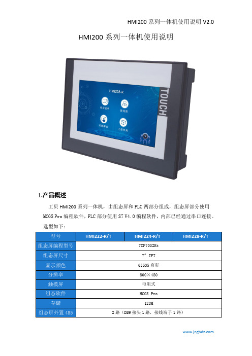
HMI200系列一体机使用说明1.产品概述工贝HMI200系列一体机,由组态屏和PLC两部分组成,组态屏部分使用MCGS Pro编程软件,PLC部分使用S7V4.0编程软件,内部已经通过串口连接。
选型如下:2.接线图3.编程说明1.一体机由组态屏和PLC两部分组成,组态屏部分使用MCGS Pro编程软件2.组态屏部分和PLC部分内部通过串口固定连接,组态屏占用的是COM1,选择如下图PLC占用的是PORT1。
两者通讯使用PPI协议,PLC端无需设置和编程,一般使用默认即可。
4.模拟量接口定义5.4-20mA两线制、三线制变送器接线示意图6.晶体管输出内部示意图7.继电器输出内部示意图8.常见问题8.1组态屏编程选择哪个型号?PLC编程选择哪个型号?答:组态屏编程软件用MCGS Pro版本,型号选择TPC7032Kt。
PLC编程软件用Step7V4.0,型号选择CPU226CN。
8.2背后的网口是属于PLC的还是组态屏的?IP地址是多少?答:属于组态屏的。
可以通过网口给组态屏下载程序,也可以实现组态屏和其它设备通讯。
组态屏默认IP是200.200.200.190。
断电重启时,连续点击屏幕可进入启动属性界面,点系统维护,点系统维护,点设置系统参数,点IP地址标签页,可进行修改。
8.3背后的USB口都有什么作用?答:属于组态屏接口,用mcgs软件制作U盘综合功能包,可以给组态屏下载程序。
也可以插鼠标或者键盘。
8.4背后的DB9接口是如何定义的?1:机壳接地2:GND3:PLC的PORT0_485信号A4:组态屏的COM2_485信号A5:GND6:+5V7:+24V8:PLC的PORT0_485信号B9:组态屏的COM2_485信号B8.5右下角有两个485通讯口,如何使用?答:标号C3的485通讯口,属于组态屏部分,在组态屏编程时选择COM3。
标号P2的485通讯口,属于PLC部分,默认PPI协议,波特率9600,地址2。
基于一种智能排障电柜的研制
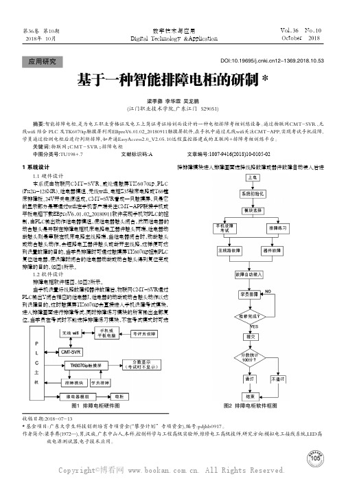
1051 系统设计1.1 硬件设计本系统由物联网CMT-SVR、威纶通触屏TK6070ip、PLC (Fx2n-128MR)、继电器模组、无线wifi、电柜Z35钻床电路或T68镗床排障板、24V开关电源组成。
CMT-SVR看成一只触摸屏,只是它的显示部分是要通过wifi在手机客户端关注CMT-APP联接手机或平板电脑下载EBproV6.01.02_20180911软件实现手机对PLC的控制,由PLC输出动作继电器模组,使继电器触头闭合,然而继电器的动合触头是并联在排障电柜机床电路电工器件触头两端,继电器动断触头则是串联在机床电路主线路端,当继电器闭合时,动断触头或动合触头动作,会短路电工器件触头或断开主线路,这样便可达到设置故障的目的。
当学员排障时可通过触摸屏TK6070ip控制PLC 复位继电器,使设障时闭合的继电器动断或动合触头得到复位完成排障的目的,如图1所示。
1.2 软件设计排障电柜软件框图,如图2所示。
当手机设置好线路故障和器件故障后,物联网CMT-SVR通过PLC输出Y闭合相应的继电器J,继电器的动断或动合触头动作以达到设障目的。
这时触摸屏TK6070ip会直接进入手机设障考试模块,进入排障画面进行排障考试,同时排障练习模块的所有输出全部复位。
当学员在考试时不能选择排障练习模块,不在考试模式时可选择排障模块进入排障画面选择线路故障或器件故障自动装入后进收稿日期:2018-07-13*基金项目:广东大学生科技创新培育专项资金(“攀登计划”专项资金),编号:pdjhb0917。
作者简介:梁季彝(1972—),男,汉族,广东中山人,本科,控制科学与工程高级实验师,维修电工高级技师,研究方向:模拟电工接线系统,LED高 效电源测试器,电子技术应用。
基于一种智能排障电柜的研制*梁季彝 李华霖 吴龙鹏(江门职业技术学院,广东江门 529051)摘要:智能排障电柜,是为电工职业资格证及电工上岗证考证培训而设计的一种电柜排障考核训练设备。
门禁系统使用说明介绍模板之欧阳引擎创编

金华职业技术学院信息工程学院欧阳引擎(2021.01.01)门禁管理系统操作说明书制作人:刘珍海日期:2014年3月25日目录(请打开【帮助H】下的【使用说明书】,这样方便您了解本系统)第1章软件的基本操作31.1 登录和进入操作软件31.2 设备参数设置41.3 部门和注册卡用户操作41.3.1 设置部门41.3.2 自动添加注册卡功能(自动发卡)51.4 基本操作71.4.1 权限管理81.4.2 校准系统时间111.5 常用工具121.5.1 修改登陆用户名和密码12第2章考勤管理功能模块132.1 正常班考勤设置132.1.1 设置考勤基本规则132.1.2 设置节假日和周休日14 2.1.3 请假出差的设置152.2 考勤统计和生成报表17 2.2.1 生成考勤详细报表172.2.2 启用远程开门18第1章软件的基本操作1.1 登录和进入操作软件1.点击【开始】>【程序】>【专业智能门禁管理系统】>【专业智能门禁管理系统】或双击桌面钥匙图标的快捷方式,进入登录界面。
2.输入缺省的用户名:abc 与密码:123(注意:用户名用小写)。
该用户名和密码可在软件里更改。
3.登录后显示主操作界面入门指南。
如果您没有经验,您可以在该向导的指引下完成基本的操作和设置。
我们建议您熟悉后, 关闭操作入门指南,仔细阅读说明书,熟悉和掌握软件的操作。
“关闭入门指南”后,操作界面如下。
1.2 设备参数设置1.3 部门和注册卡用户操作1.3.1设置部门点击【设置】>【部门】,进入部门界面。
点击【添加最高级部门】。
输入“总经办”,点击【确定】。
想在该部门下再添加部门,可点击【添加下级部门】。
1.3.2自动添加注册卡功能(自动发卡)用途:可以通过自动刷卡批量添加用户,避免输入的繁杂和出错。
批量设置卡片或者卡片上没有印刷卡号时,均可以考虑采用该方法,用USB发卡器或者任何一个门的读卡器做发卡器,实现自动发卡功能。
动环FSU对门禁的规划及安装调测说明-以安科为例之欧阳与创编

目录动环FSU门禁安装调测说明 (2)前言 (2)一、接线说明 (2)1.1 高新兴接线说明 (2)1.2 邦讯接线说明 (3)1.3 中兴力维接线说明 (5)1.4 艾默生接线说明 (6)二、调试说明 (12)2.1 平台增加非智能门禁 (10)2.2高新兴调试说明 (11)2.3 邦讯调试说明 (13)2.4 中兴力维调试说明 (15)2.5 艾默生调试说明 (19)三、功能验证 (20)3.1 远程开门验证 (21)3.2 门磁、锁舌告警验证 (22)动环FSU门禁安装调测说明前言铁塔门禁设备正确连接调试后,可以在运维监控系统“http://180.153.49.130:9000/baf/jsp/uiframe/login .jsp ”实现平台远程开门、门磁告警上报、锁舌告警上报。
一、接线说明1.1 高新兴接线说明第一套门锁:门磁1接上排接线端子的IN12通道和GND,锁舌1接IN21和GND,门锁供电接上排接线端子的12V和GND,门锁1DO控制分别接DO3公共,DO3常开串一根线到GND。
第二套门锁:门磁2接上排接线端子的IN13通道和GND,锁舌2接IN22和GND,门锁供电接上排接线端子的12V和GND(IN21通道前的12V),第2套门锁的DO控制分别接DO4公共,DO4常开串一根线到GND。
1.2 邦讯接线说明设备左下角的“DC12V输出”为FSU的12V电源输出端,左脚为+、右脚为-,如下图:设备水印上标注的门磁1对应FSU的DI-11通道,设备水印上标注的门磁2对应FSU的DI-12通道,如下图:1设备接线定义门锁电源线:门锁的电源正、负极分别接入FSU12V输出端的正、负极;第一把锁:1、门磁:门磁的两根线,第一把门锁:低电平接入DI-9左侧的GND,高电平接入DI-11通道;2、锁舌:锁舌的两根线,第一把门锁:低电平接入DI-9左侧的GND,高电平接入DI-12通道;3、门锁控制:第一把门锁控制线接入DO-3的NC(常闭)端口,再从DO-3的com(公共)端口接入一根线到FSU12V输出端的负极;第二把锁:门磁:第二把门锁:低电平接入DI-9左侧的GND,高电平接入DI-13通道锁舌:第二把门锁:低电平接入DI-9左侧的GND,高电平接入DI-14通道;门锁控制:第二把门锁控制线接入DO-4的NC(常闭)端口,再从DO-4的com(公共)端口接入一根线到FSU12V输出端的负极。
- 1、下载文档前请自行甄别文档内容的完整性,平台不提供额外的编辑、内容补充、找答案等附加服务。
- 2、"仅部分预览"的文档,不可在线预览部分如存在完整性等问题,可反馈申请退款(可完整预览的文档不适用该条件!)。
- 3、如文档侵犯您的权益,请联系客服反馈,我们会尽快为您处理(人工客服工作时间:9:00-18:30)。
Charge LED LED´s : Status of the CAN network : to select/change mode : moving cursor and indexing through the parameter groups : can scroll through and change monitor codes, parameter groups : to store data LED display : 7-segment display (5-digit)
▲ to run the motor CCW
Press M key to exit JOG mode
Schneider Electric
- Motion & Drives training
- Lexium 23 plus
´04/2010
13
Exercises 3.3 – HMI
Fault record ● Display of the current Fault Record
- Lexium 23 plus
´04/2010
5
HMI (Human Machine Interface)
Monitor status
● In monitor mode the user can specify the monitor status by changing the parameter P0-02. ● When drive is switched on, the monitor status depends on the setting value of P0-02. For example: P0-2 setting = 4. After power on the monitor function will be: “input pulse number”.
● If you change:
- the operating mode/motor direction - modbus adress you have to reboot the device !
Schneider Electric
- Motion & Drives training
- Lexium 23 plus
You have to set P0-35 to 0x 02040202 The values of P2-02 and P2-04 will be displayed by P0-25 With parameter setting P0-02 = 19, the content of P0-25 will be displayed as monitor status.
Schneider Electric
- Motion & Drives trainiቤተ መጻሕፍቲ ባይዱg
- Lexium 23 plus
´04/2010
14
Exercises 3.4 – HMI
Fault memory ● Display of the error memory P4-00
Select Parameter P4-00
Reset parameter settings
saved
1. display
rst
2. display
done 3. display
Reboot the drive
Schneider Electric
- Motion & Drives training
- Lexium 23 plus
´04/2010
Schneider Electric
- Motion & Drives training - Lexium 23 Plus
´04/2010
Summary Central document
2
HMI (Human Machine Interface)
Overview – HMI
Integrated HMI LED´s only on LxM23 A
The parameters will be mapped by P0-35 till P0-P42.
example:
You want to read/write two 16-bit parameters via P0-25: - P2-02 (PositionFeedForwardGain) - P2-04 (ProportionalSpeedLoopGain)
P0-00
Select Parameter P0-00 Display of the firmware version
- Motion & Drives training
- Lexium 23 plus
´04/2010
11
Exercises 3.1 – HMI
Reset to factory settings ● Select the Parameter P2-08 P2-08 Special factory setting 00010
ENT
Display the most recent fault record
P4-01 Select Parameter P4-01 ENT Display the second most recent fault
record
P4-02, P4-03, P4-04
Select Parameter P4-02,P4-03,P4-04 for the third, fourth, fifth recent fault record
- Lexium 23 plus
´04/2010
9
Switching on the first time
● After switching on the servo drive, the device goes through a initialization routine; all LED´s are tested, all segments of the 7-segment display and the LED´s light up. ● After the initialization the device is ready for operation. Default operating mode is the “Pt operating mode”. ● The functions for the inputs and outputs will be set to default settings after initialize a “Reset to factory settings” and repower the drive.
- Motion & Drives training
- Lexium 23 plus
´04/2010
4
HMI (Human Machine Interface)
Keypad operation
Parameter Mode
Schneider Electric
- Motion & Drives training
Schneider Electric
- Motion & Drives training
- Lexium 23 plus
´04/2010
6
HMI (Human Machine Interface)
Monitor status
● P0-9 till P0-13 is used to display the status value determined by P0-17 till P0-20.
12
Exercises 3.2 – HMI
Jog Mode ● Parameter P2-30 has to be set to 1 (Servo On) P4-05
Adjust JOG speed to 75
ENT
Press ENT to activate JOG mode
JOg
Display that JOGmode is active Press▼OR OR CW
Lexium 23 Plus
HMI / FSU + Exercises HMI
Motion & Drives Training
Lexium 23 plus
Summary
> > > > > > > > > >
Product overview Motors HMI, FSU + Exercises HMI Electrical installation Status and Drive fault + Exercise Initial Parameter Wizard + Exercise Operating modes, PR Mode + Exercise Operating modes, + Exercises Tuning, LCT menu + Exercise Lexium 23 A, CANopen
´04/2010
10
Factory setting
● Parameter P2-08 can be used to reset all parameters to their original factory setting and enable some parameter functions ! ● To perform a reset to factory setting the drive has to be disabled.
Schneider Electric
