xmt80x智能pid温控仪-精选文档17页
XMT智能数显示控制仪表使用说明书样本
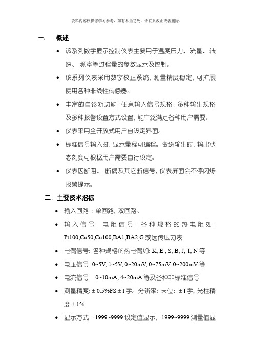
一.概述●该系列数字显示控制仪表主要用于温度压力、流量、转速、频率等过程量的参数显示及控制。
●该系列仪表采用数字校正系统, 测量精度稳定, 可扩展使用各种非线性传感器。
●丰富的自诊断功能, 任意输入信号规格, 多种输出规格及多种报警设置方式设置, 能广泛满足各种用户需要。
●仪表采用全开放式用户自设定界面。
●标准信号输入时, 显示量程可编程。
变送输出时, 输出状态刻度可根椐用户需要自行设定。
●仪表因断阻、断偶及其它断信号, 仪表屏面会不停闪烁报警提示。
二.主要技术指标●输入回路: 单回路, 双回路。
●输入信号: 电阻信号: 各种规格的热电阻如:Pt100,Cu50,Cu100,BA1,BA2,G或远传压力表●电偶信号: 各种规格的热电偶如: K, E , S, B, J, T, N等●电压信号: 0~5V, 1~5V, 0~20mV, 0~75mV, 0~200mV等●电流信号: 0~10mA, 4~20mA等及各种非标准信号●测量精度:±0.5%FS±l字。
分辨率: 末位: ±l字, 光柱精度±1%●显示方式: -1999~9999设定值显示, -1999~9999测量值显示, 发光二极管工作状态显示, 光柱显示过程量的百分比。
●输出信号: 模拟量输出: 0~10mA、负载≤1KΩ, 4~20mA、负载≤500Ω0~5V, 1~5V要求负载电阻≥250KΩ●开关量输出: 继电器控制输出( AC220V , 3A无感负载)●报警方式: 用户可根据要求自行设定。
●恒压电源输出: DC24V电源输出, 供二线制变送器使用。
●使用环境: 温度: 0~50℃, 相对湿度: 85%RH以下避免强腐蚀性气体●工作电源: AC220±10% 50HZ±2HZAC96~260V ----------开关电源DC24V±2V ----------开关电源DC220V±20% ----------开关电源●功效: 约6W●重量: 约0.5Kg三.操作指南1.各部分名称:.过程量及参数代码2.名称及功能内容3.操作方式3.1: 一级参数的设定方式( 单显示仪表无此项程序)●正确接线: 请参照仪表随机接线图接妥输入输出及电源线, 并请确认无误。
XMT系列数显温控仪使用说明

XMT 系列数显温控仪 使用说明XMT7000系列温度控制仪是本公司最新推出的一种高性能、高可靠性的智能型工业调节仪表,可进行热电偶、热电阻、模拟量等多种信号自由输入,量程自由设置,同时多种输出方式;运用模糊理论结合传统PID 方法,控制快速平稳 ,测量精度高,抗干扰能力强,操作简单等优点,其广泛应用于机械、化工、陶瓷、轻工、冶金、石化、热处理等行业的自动温度控制。
技术参数产品符合《《Q/320401HBD001—2000XMT 系列PID 智能温度调节仪》》标准的要求 □ 操作说明及开机输入类型显示表仪表上电后,PV 窗口显示输入类型,SV 窗口显示最大量程,然后PV 窗口显示测量值,SV 窗口显示设定值。
这是仪表的标准显示方式。
(二)各参数意义说明 (三) 仪表工程师调整参数说明按S E T 键2秒在PASS状态下,输入8803(三位显示为803)后按设定键,即可恢复至常规参数。
(五)关于定时功能的补充说明当ET=1或2时(1以分为单位,2以秒为单位),仪表将使能定时功能。
定时功能使能后,定时时间到后(或温度超过设定值+AH值),仪表会自动切断输出(报警不受影响),并通过第二报警输出一个警报通知信号(长短可调),从而方便有定时要求的恒温控制(可以做到无人值守)。
当定时功能使能后,设定温度时会显示一个SP菜单,再按一下设定键设定时间时会显示一个ST菜单.当定时功能使能后,AT指示灯用作运行/停止状态指示灯(原功能不受影响).在测控状态下,按加键可使SV窗口在设定温度与剩余定时时间之间切换,当SV显示剩余定时时间时,个位上的小数点会闪烁.定时时间到达后,仪表的主控继电器会停止输出,同时运行灯熄灭。
此时可用按住减键3秒钟重新启动一个定时周期。
只有当测量温度达到设定温度减ALT的差值时,定时倒计数才开始运作.否则虽然AT灯亮,但定时时间并不减少。
一个定时周期结束后,由BL参数决定第二报警继电器的动作。
XMT 808 系列 智能温度控制仪表 使用说明书

XMT* 808系列 智能温度控制仪表 使用说明书(万能输入)万能输入版本2007目 录目 录 (1)安全注意标志 (3)第一章 概述 (3)第二章 技术指标 (4)2.1输入规格 (4)2.2测量精度 (4)2.3响应时间 (4)2.4调节方式 (4)2.5输出规格 (4)2.6通 讯 (4)2.7报警功能 (4)2.8隔离耐压 (4)2.9手动功能 (4)2.10电源供电 (4)2.11工作条件 (5)2.12产品认证 (5)第三章 产品选型 (5)3.1型号意义 (5)第四章 安装与接线 (5)4.1 XMT-808接线图 (6)4.2 XMTD-808接线图 (6)4.3 XMTA/E/F-808接线图 (7)4.4 XMTG-808接线图 (7)4.5 可控硅触发接线图 (8)第五章仪表面板说明 (8)5.1仪表面板图 (8)5.2面板说明 (8)第六章基本设置及操作 (9)6.1温度给定值设置 (9)6.2参数设置 (9)6.3手动/自切换 (9)6.4自整定操作 (9)6.5手动自整定 (10)1第七章功能及设置 (10)7.1操作流程图 (10)7.2参数功能说明 (11)第八章部分功能的补充说明 (16)8.1线性电流输出 (16)8.2时间比例控制 (16)8.3远传压力控制 (17)8.4热电偶冷端补偿 (17)第九章 仪表常用控制方式 (18)9.1二位式调节/仪表报警 (18)9.1.1二位式调节介绍 (18)9.1.2二位式调节举例 (18)9.2温度变送 (18)9.2.1温度变送介绍 (18)9.2.2温度变送举例 (18)9.3通讯功能 (18)9.3.1通讯功能介绍 (18)9.3.2通讯功能接线 (19)第十章 故障分析及排除 (20)附1:仪表参数提示符字母与英文字母对照表 (20)第十一章产品服务指南 (21)2安全注意标志在阅读说明书时会出现以下标志,分别表示“危险”、“注意”。
XMT智能仪表说明书

报警输出
0
无输出
1
上限报警
2
下限报警
3
正偏差报警
4
负偏差报警
5
组合报警
辅助输出
0
无输出
1
RS485
2
RS232
3
4-20mA
4
0-10mA
5
1-5V
6
0-5V
输入类型
1
2
3
4
5
6
7
8
9
a
1
适配热电偶
2
适配热电阻
3
适配霍尔变电阻
4
适配远传压力表
5
适配直流0-10mA
6
适配直流4-20mA
当仪表选择外部给定功能时,外部给定值以1—5V的形式输入。当外部给定信号小于1V时,则仪表自动取消外部给定功能,改为内部给定值。利用外部给定功能,可以实现串级PID调节功能。
当直接控制阀门时,控制输出(OUT)位置的继电器控制为正转,第一报警位置(AL1)位置继电器控制反转。AL1不在作报警输出使用,阀门位置反馈信号以0-5V的形式输入。
[注]:如用户订货时注明输入电流及范围,则厂家可以将取样电阻安装在仪表内部。
[PID]控制输出方式:
代码
0
1
2
3
4
5
6
7
8
T
输出方式
无输出
继电器
SSR
SCR
三相SCR
4-20mA
0-10mA
1-5V
0-5V
特殊规格
当仪表控制三相SCR触发工作时,控制输出(OUT)触发两相SCR;第一报警(AL1)与控制输出(OUT)同步动作,触发第三相SCR,触发方式为过零触发。此时,第一报警(AL1)不再作为报警输出使用了。仪表的所有控制输出与输入信号完全隔离。
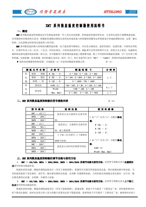
XMT系列数显温度控制器使用说明书
6、超限报警:报警输出点在被测信号超过设定值的2—
10%(全量程),消警范围≤1%;
7、触点容量:AC220V、3A(阻性负载),或1A(感性
负载);
8、工作电源:AC220V±10%、50Hz,功耗小于±2W;
9、工作环境:温度0 ~ 50℃,相对湿度30~ 85%的
无腐蚀性气Leabharlann 场合; (图一)10、型尺寸及开孔尺寸:(见表3)
或使用不当所致,本司负责产品终身维修,由用户酌付修理成本费;
4、附件:安装紧固件一副,使用说明书一份;
5、本司生产的TEA、TED、TDW等动圈型旋盘式温控表的使用性能及接线方法与XMT系列数显温控表一样,但价格便宜,
适合在对控温精度要求不高的工作环境。
将温控表的电源、测温传感线连接妥后(详见下面接线图),接通电源,将扭子开关拨至“下限设定”处,同时旋转相对应
的下限设定旋钮,此时仪表显示屏上显示的数字是要设定的下限温度值;接着将扭子开关拨至“上限设定”处,旋转相对应的上
限设定旋钮,此时仪表显示屏上显示的数字是要设定的上限温度值;再将扭子开关拨至“测量”处,此时仪表显示屏上显示的数
型 号 规 格
控 制 功 能
XMT(XMZ)系列智能数字显示控制器说明书

adjustable return difference, AH model.
XMZ-204 F:
Two-stage, transferable type, resistance remote pressure transmitter, without
transmitter, F model.
XMZ-121 AL-S: Three-stage, popularize type, Thermocouple, without transmitter, AL type, S
Analog value input
Digital display meter
Illustration:
XMZ-101AH-K: Single display, popularize type, Thermocouple, without transmitter, AH type, K
calibration number.
calibration number.
XMZ-126 NH:
Three-stage, popularize type, 3 types popularize type and 4-20 mA
simulated quantity to input (tape DC24V) and NH model.
XMZ-127 BF:
XMZ-102D-Pt100: Two-stage, popularize type, without transmitter, Thermocouple, D type,
Pt100 calibration number
XMZ-205GAH: Two-stage, transferable type, standard signal input, without transmitter,
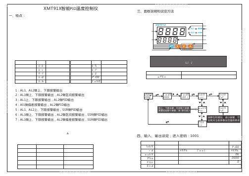
智能PID温度控制仪说明书
故障信息 未接入传感器或传感器短路
2 、参数设定方法
2 0 00
2 0 00
1:AL 1、AL 2做上、下限报警输出 2:AL 1做上、下限报警输出,AL 2做区间报警输出 3:AL 1上、下限报警输出,AL 2做PID输出 4:Al 1做偏差报警输出,AL 2做PID输出 5:AL 1、AL 2上、下限报警输出,SSR做PID输出 6:AL 1做上、下限报警输出,AL 2做区间报警输出,SSR做PID输出 7:AL 1做上、下限报警输出,AL 2做偏差报警输出,SSR做PID输出 5 、继电器触点容量:A C 2 5 0 V7 A (5 0 0 瓦功率以上,需加交流接触器) 6 、继电器触点寿命:1 0万 次 7、 固态继电器驱动能力:D C 2 4 V (5 0 mA) 8 、工作温度:1 0 ~5 0 ℃ 9 、外形及开孔尺寸:5 种型号和外形尺对照如下: 型号 X MT 9 1 2 X MT 9 1 3 X MT 9 1 4 X MT 9 1 5 X MT 9 1 6 外形尺寸(mm) ×1 1 0 4 8 ×4 8 ×9 6×8 5 4 8 9 6×4 8×8 5 7 2 ×7 2×1 1 0 9 6 ×9 6×8 5 开孔尺寸( mm) 4 4 ×4 4 4 4 ×9 2 9 2×4 4 6 8 ×6 8 9 2 ×9 2
A 1 H(1 0 0 ) A 1 L(8 0 )
报警 报警
下限报警继电器动作规则
+
A 1 L < A 1 H :下 限报警 P V < A 1 L继 电器吸和 P V > A 1 H继 电器释放 测量值小于8 0, 继电器吸和 测量值大于1 0 0, 继电器释放
8
SSR DC 24 V
XMT系列数字显示控制仪说明书

图 4 、- 7 型仪表接线图
X M T 系列智能数字显示控制仪
注: 1、仪表内部带有热电偶冷端补偿部件,短接端子 8 和 10,可 以去掉仪表内部的冷端补偿功能。
13
X M T 系列智能数字显示控制仪
利用接线方式选择热电偶冷端补偿模式
温度补偿信号采用热电偶作为输入信号时,根据热电偶 测温原理,需要对热电偶冷端进行温度补偿方可保证测量准 确,仪表测量仪表周围环境温度并对热电偶冷端进行自动补 偿,但由于测量元件的误差及仪表本身发热原因( 仪表接线 端子上温度往往同步升高) 常导致自动补偿方式偏差较大。 故在对温度测量精度要求非常高的应用中,提供高精度的补 偿模式供用户选择。注意:不正确的补偿将使得测量误差大 大增加,仪表对热电偶信号的测量精度可高达 0.2 级精度以 上,但此精度不包含内部冷端自动补偿误差。 仪表的软件可通过不同的接线方式选择 2 种补偿模式,提 供完善的热电偶冷端补偿方案。 ( 1 ) 内部自动补偿:仪表出厂时均采用这种模式,能满足 通常的工业应用。但由于感温器安装在仪表内部,易受仪表 内部发热影响,同时也受补偿导线接线及周围环境( 如有可 控硅散热器) 的影响。其对测量造成的不一致性在条件最坏 时可能达 2℃。 (2)外接 Cu50 型铜电阻传感器进行补偿:补偿精度高。对 测量精度要求高的用户可另外购买一只小型 Cu50 型铜电阻, 并最好外置一只接线盒,将铜电阻及热电偶冷端都放在一起 并远离各种发热物体。由补偿造成的测量不一致性一般小于 0 . 5 ℃,要求测量精度高的用户应使用该种方法。
○
○
○
○
○
○
○
○
○
○
○
○
○
○ 22
Loc
2、 仪表测量显示设定参数
XMT-808系列仪器用户手册说明书

XMT*-808SERIES INSTRUMENT USER M ANUAL The instrument is controlled by a microcontroller,can be input RTD,thermocouple and other signal freely,can be set the positive and negative control arbitrarily and offers four alarm modes.Its control outputs can be manually switched automatically,and there are two automatic outputs to choose,PID or two position control.When used in a variety of different systems,the instrument will adjust the parameters themselves to get a satisfactory control effect without characteristics of overshoot and disturbance,so it can be widely used for various temperature control and measurement applications.Ⅰ.Technical Specifications1.Measurement Accuracy:±0.5%℃2.Cold Junction Compensation Error:≤±2.0℃3.Sampling Period:0.5second4.Control Period:relay output is from2seconds to120seconds5.Output Relay Rating:AC277V/3A or AC120V/3A6.Input AC Power:AC85~242V(switch power supply),50/60Hz7.Working Environment:Temperature0~40.0℃,Humidity≤85%RH,non-condensingⅡ.Model Code DefinitionXMT□—8□812341:The surface dimension(mm)A:96×96×110Installation hole92×92D:72×72×110Installation hole68×68E:48×96×110Installation hole44×92G:48×48×110Installation hole44×442:Series Number:800series3:Additional Alarm:‘0’:No alarm;‘1’:the upper limit alarm‘2’:the lower limit alarm.Input::‘8’input signal can interchange freely(no voltage and current input)4:InputⅢ.Panel Chart1.PV Display:it will display measured temperature value,or displayparameters code when setting parameters.2.SV Display:it will display the set point of the running programsegment or display parameters code when setting parameter.3.ALM1Indicator:if this indicator is on,the instrument has acorresponding ALM1relay outputs.4.ALM2Indicator:if this indicator is on,the instrument has acorresponding ALM2relay outputs.5.A-T Indicator:the indicator will be on under the process of self-setting.6.Out Indicator:if it is on,the OUT control terminal will have outputsignal.7.Function Key(SET):press the key for three seconds to set parameter,or press both the key and Shift key simultaneously to enter theprogram segment setting.8.Shift Key:i.e.⊳arrow key,press the key to shift the flashing decimalposition among the SV display window for modifying the number.9.Down Arrow Key:press the key to decrease the value when settingparameters and temperature value or under manual control.10.Up Arrow Key:press the key to increase the value when setting parameters and temperature value or under manual control.Ⅳ.Parameters Code Setting TableNOCode NameSettingRangeFunction DescriptionFactorySetting 0Temperature SettingValuedetermined by the P-SL,P-SH refer to6.2“modify temperature setting value”1001Temperature alarm1The limit alarm setting range isdetermined by the P-SL and P-SH;Positive and negative deviationalarm is set in the range of0.5to100.0.Set temperature alarm1value,refer toALP12002Temperature alarm2Set temperature alarm2value,refer toALP21003Proportional Band0~100It determines the size of system proportional gain,the greater P value is,the smaller proportion effect is,the smaller overshoot is,and the heatingtime will rise as the consequence of too small P value;When P is set as0,the instrument will work under two-position control.54Integration Time0~2000SSet the integration time to relieve residual bias,occurring underproportional control.A large integration time will slow system to reachequilibrium,while a very small integration time will make systemfluctuate.2405Derivative Time0~200SSet the derivative time to prevent output fluctuating too much andimprove control stability.306Parameter Self-setting/:open the self-tuning function;:turn off self-tuning function;After selecting,the controller will conduct a self-tuning procedure,and then automatically return to.7Control Period1~120SSet relay control operation cycle.It doesn’t act under two positioncontrol208Hysteresis0.1~50.0It only acts under two-position control(P=0)0.59Alarm1outputHysteresis0.1~50.0Hysteresis for alarm contact output settings(unilateral hysteresis).Example:When ALP1is set to1:An alarm when the measuredvalue≥AL1,AL1indicator will be on;When the measured value≤(AL1-HY1),the alarm disarmed,and the corresponding AL1indicator will be off.0.510Alarm2outputHysteresis0.1~50.00.511Sensor errorcorrection-20.0~20.0sensor Error correction value012Filter coefficients0~50Filter constant of measured sampling software.The bigger constant is,the stronger anti-interference ability is;but it will make both the measure speed and system response slower2013Display accuracy0or10:have decimal point,1:have no decimal point014The upper limit P-SL~full range Define a given value and set the alarm value range respectively;P-SH≥P-SL;refer to the parameter"Sn"to find the maximum setting rangecorresponding to each index numbers130015the lower limit Range start~P-SH016output max value0.0~OUTHThe maximum and minimum output power can be achieved,and it willnot act by manual action or under two-position control.OUTH≥OUTL17output min value OUTL~200.020018Alarm1outputdefinition0~4‘0’:no alarm‘1’:upper limit alarm‘2’:lower limit alarm‘3’:positive deviation alarm‘4’:negative deviation alarm119Alarm2outputdefinition0~4220Select ON/OFFcontrolON/OFFOFF:reverse control(control heating)ON:positive control(control cooling)21Start machine forcontrolling outputpower0~100Soft-start function,which means that for the first time after power meteroutput power factor22Code lock0~50To unlock the operate options,set LOCK code to0.To modify SP or TE,set lock=1;To forbid to modify all the parameters,set lock>123Input typeCU50()PT100()PT100()K()E()J()T()S()CU50(-50.0~150.0℃);PT1(-200.0~200.0℃);PT2(-200.0~600.0℃);K(-30.0~1300℃)E(-30.0~700.0℃);J(-30.0~900.0℃);T(-200.0~400.0℃);S(-30.0~1600℃);24Output OptionsRLP()SSR()Zero()Mut()0~10mA()4~20mA()1,RLP:Relay output2,SSR:Solid state relay output3,Zero:SCR zero trigger output4,Mut:SCR phase trigger output5,0~10mA Linear control current output;6,4~20mA Linear control current outputRLPⅤ.Flow ChartⅥ.O peration1.Parameter setting:connect the sensor properly according to the connection scheme,after power on,press the SET key3S to modify the parameter,the meter will display the parameter code1~24alternate at the upper row and display the parameter data in the lower row in the window.Then press the▲.▼or⊳key to adjust the parameter,next press the SET key to save.It will automatically save the data and withdraw the setting,if there is no action done by pressing any key more than60seconds.Note:P arameter22is LOCK code,t o unlock the operate options,set LOCK code to0;to modify SP or TETE,,set lock=1lock=1,,couldn’’t set the parameter larger than50,o therwise it will parameters,,set lock>1>1..t he user couldnt o forbid to modify all the parametersoriginal al setting.return to factory origin2.Modify the set temperature value:connect the sensor properly according to the connection scheme,after power on,pressthe SET key to enter into setting area,do the same way as the above set the parameter “SP”3.Manual operation:connect the sensor properly according to the connection scheme,after power on,press the SET key 3S to enter into manual operation,and the lower left side of the digital display "H",then press ▼,▲key to set the output power percentage at the range of 0and 100,press ⊳key to quit directly.Ⅵ.S etting I tselfIf bad performance found when the meter first used,or due to terrible condition,the parameter,such as P.I.D,should be set again as follows :after setting the desired value,set HY as 0.5~1.0℃,set “AT”as ON ,A-M indicator shall flash,the meter enter into the auto-setting state,and the instrument is under ON/OFF(two-position)control ;After three vibration,the instrument will automatically save P.I.D parameter,A-M indicator shall goes out,the setting process is over.Note :①If the power is cut when the meter is under the process of auto setting,it will restart setting next time owing tothe meter memory ;②If the setting should be over,just set “AT”as OFF,then the meter shall exit,but the setting result will be invalid.Ⅶ.Connection SchemeⅧ.I nstallationFirst insert the controller into mounting hole,than put the attached mounting bracket into the instrument holes,finally moderately tighten the installation screws.Be careful not to tighten the screws too tightly,so as not to damage the instrument.Meter space should be greater than 3cm.X .Fault Analysis and ClearanceXMT*-808series instruments adopt advanced production technology,and the strict test have been done before leaving factory,which guarantees the quality and reliability of the meter.The usual fault was most caused by the wrong operation or parameter setting according to daily application.If you find the fault that you couldn’t cope with,please record it,and contact with the agent or us directly.Sheet 9-1is the usual fault of XMT*-808series in the daily application :Sheet 8-1Common FaultFaultyyandClearanceAttached:ComparisonTablebetweenMeter eter’’s P arameter Code and English L etter N ote:we will continue to improve product technology,design specification w ithout notice.Faulty CausesClearanceAbnormal power 1.Poor contact of power cord 2.Power switch without close Check the powerSignal display notcorrelate with the fact.(display ‘HH’or‘LL’)1.mismatch wrong sensor2.connect wrong signal 1.Check sensor model and input type of the meter2.Check signal wire Abnormal output controlWrong connecting output wireCheck output connectionA B C D E F G H I JKLMNOPQRSTUYAll in order to prevail in kind!。
智能控制器温度控制器万能输入控制器批发PID控制器批优秀文档
额定功率: / 工作电压: AC220V
工作电压: AC220V 智工能作控 电制压器: 温AC度22控0V制器 万能输入控制器批发 PID控制器批 XMT智能显示仪 工作电压: AC220V
智能控制器 温度控制器 万能输入控制器 批发 PID控制器批 XMT智能显示仪
、简介
加工定制: / 工作电压: AC22控制器批发 PID控制器批 XMT智能显示仪
工作电压: AC220V
型号: XMT系列 工作电压: AC220V
规格: XMT 智工能作控 电制压器: 温AC度22控0V制器 万能输入控制器批发 PID控制器批 XMT智能显示仪
工作电压: AC220V 工智作能电 控压制:器 A温C度22控0V制器 万能输入控制器批发 PID控制器批 XMT智能显示仪
品牌: 汇邦 工作电压: AC220V
智工能作控 电制压器: 温AC度22控0V制器 万能输入控制器批发 PID控制器批 XMT智能显示仪 工作电压: AC220V 工作电压: AC220V 智能控制器 温度控制器 万能输入控制器批发 PID控制器批 XMT智能显示仪 工作电压: AC220V
感谢观看
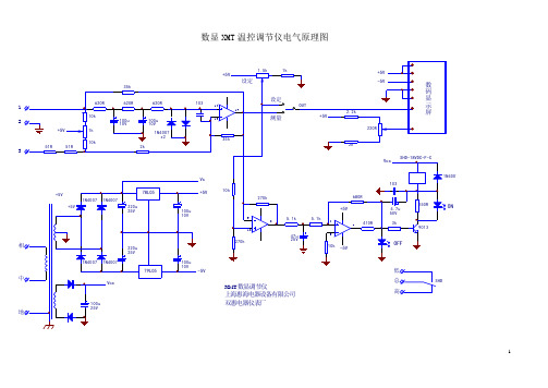
数显XMT温控调节仪电气原理图
数显XMT温控调节仪电气原理图
1
2
3
ON
IC供电采用两路正负5V电源,继电器供电由整流12V直接供给,未经稳压;
JT100热电阻传感器,将温度变化转化为电阻值变化,经运算放大器放大后分为两路:一路经测量/设定转换开关送入数码显示屏,显示测量温度值;
一路送入后级迟滞电压比较器,再经同相放大器,三极管9013驱动控制继电器。
由继电器控制外接接触器,实现对加热器的通、断电控制,达到恒温控制要求。
数码显示屏,为一只200mV量程的电压表头,220R电阻为量程校准调节;
当测量/设定开关置于设定位置时,可由1.5k电位器设定温控点。
同时设定值也可在显示屏上显示,比较方便。
同时设定值也作为迟滞电压比较器的基准电压,输入IC的同相输入脚。
使加热控制动作点随设定值的高低而变。
(完整版)XMT数显调节仪使用说明.docx

XMT数显调节仪使用说明一、概述XM系列数字仪表采纳先进事迹的中大规模集成电路,并应用了独特的非线性校正持技术,与传统的 XC系列动圈式仪表、一般TD和 TE 系列模拟式仪表相比,具有精度高、可靠性好、抗振性强、安装方便、读数清晰、无视差、可远距离观看等独特优点,并具有二位式、三位式、上下限位差、时间比例、可控硅连续调节、位式PID、PID 连续调节、 PID 自整定操纵、电脑模糊操纵等多种操纵方式,依照需要还能够增加超温报警功能,是XC 系列仪表、 TD 及 TE 系列仪表理想的更新换代产品,可广泛应用于冶金、化工、电子、机械、纺织、塑料、制冷、医疗、电炉等轻、重工业部门作 -200 ℃~ 1600 ℃范围内的温度测量和自动操纵。
配上相应的传感器也可用于压力、流量、液位等参数的显示和操纵。
二、要紧技术指标1、显示方式:三位或四位LED数码管直截了当显示被测值;2、显示误差:小于±0.5%F· S± 1 字、小于± 1%F· S± 1 字二档;3、设定点偏差:小于±0.5%F· S、小于± 1%F· S 二档;4、执电偶冷端补偿:0~ 50℃内误差小于2℃;5、位式操纵切换差小于 1.0%或 0.3%;6、时间比例调节:比例带1%~ 4%,周期: 30s ± 10s ;7、 PID 调节:〔1〕 P〔比例带〕 3%;〔2〕 I 〔积分时间〕 250s;〔3〕 D〔微分时间〕 50s;〔4〕输出 0~ 10mA负载 R=1K;输出 4~20mA负载 R=510Ω;8、输出脉冲信号:幅值大于3V,宽度大于40us 的移相脉冲及电流小于1A 的通断过零触发;9、输出触点容量:交流220V/7A〔直截了当操纵功率1kW以下,阻性负载〕,大功率时〔直截了当操纵功率3kW以下,阻性负载〕;10、温度系数:0~ 50℃范围内使用时,其温度系数小于0.05%/ ℃;11、工作电源:〔 180~ 240〕VAC,50Hz,功率小于4W;开关电源〔 85~242〕VAC, 50Hz/60Hz;12、工作环境:温度0~ 50℃,相对湿度小于85%的无腐蚀性气体场合。
