Hirschmann OpenRail产品安装配置
Hirschmann OpenRail产品介绍

RS2-xx/xx
RS20-0800xx
Slide: 16
Automation and Network Solutions
RS20-1600xx RS20-1600xx有8款标准产品: 有 款标准产品 款标准产品:
RS20-1600T1T1SDAE RS20-1600T1T1SDAP RS20-1600M2T1SDAE RS20-1600M2T1SDAP RS20-1600M2M2SDAE RS20-1600M2M2SDAP RS20-1600S2S2SDAE RS20-1600S2S2SDAP
Slide: 2
Automation and Network Solutions
OpenRail - Modular Switches
Slide: 3
Automation and Network Solutions
MS20-0800xx
MS2108-2
MS20-0800xx
MS20-0800xx有2款标准产品: 有 款标准产品 款标准产品: MS20-0800SAAE 8xFE,标准温度,增强版固件 ,标准温度,增强版固件 MS20-0800SAAP 8xFE,标准温度,专业版固件 ,标准温度,专业版固件
Slide: 21
Automation and Network Solutions
Open Rail 命名规则
Slide: 22
Automation and Network Solutions
RS/MS的端口数和端口类型 的端口数和端口类型
交换机的端口数 RS20:4口、8口、16口和 口 口和24口 : 口 口 口和 RS30:10口,18口和 口(包括 个千兆端口) : 口 口和26口 包括2个千兆端口 个千兆端口) 口和 MS20:8口和 口(通过 口和16口 通过MB-2T可扩展为 口) 可扩展为24口 : 口和 可扩展为 MS30:10口和 口(通过 : 口和 口和18口 通过MB-2T可扩展为 口) 可扩展为26口 可扩展为 Uplink端口类型 端口类型 T1: 双绞线 / RJ45(100/1000Mbps) : ( ) T5: 双绞线 / M12(100Mbps) : ( ) M2: 多模光纤 / SC(100Mbps) : ( ) M4: 多模光纤 / ST(100Mbps) : ( ) S2: 单模光纤 / ST(100Mbps) : ( ) L2: 单模光纤 LH / ST(100Mbps) : ( ) O6: SFP slot(1000Mbps) : ( )
HP Openview上HERMES SoftLab Oracle Siebel CRMOracle BI Smart Plug-in的安装与配置

Installing on the HPOM Management Server
- Install SPI for Siebel on the HPOM Management Server
Configuring on the HPOM Management Server
- Configure the HPOM Management Server
Installing and Configuring HERMES SoftLab Oracle Siebel CRM/Oracle BI Smart Plug-in for HP Software on Windows
Installation and Configuration Overview
Verifying the Installation and Configuration
- Verify the Installation - Verify the Configuration - Verify Licensing
Installing Reports
- Install Reports
Note:* XX.XX is the version of the package, for example, 03.20
Installing the HPOM Management Server
- Install SPI for Siebel on the HPOM Management Server
Licensing
- Deploy the Licensing Policy on Managed Nodes - Generate License Request File - Obtain License Activation File - Merge and Deploy the License Files
赫斯曼交换机配置产品安装配置

P1/P2-电源1/2LED: 绿色-该路电源供电正常 熄灭-该路电源低于18V
R1/R2-信号触点LED: 红色-故障信号触点输出,故障报警 黄色-故障信号触点输出,人工定义 熄灭-故障信号触点关闭
RM-冗余状态LED: 绿色-环网管理生效,环网无断点 黄色-环网管理生效,环网断开 熄灭-环网管理关闭 闪烁-错误的环网配置 RUN-运行/启动LED: 绿色-设备系统就位,正在运行 黄色-设备系统正在启动过程 熄灭-设备系统重启
1 2 3 4 5 6 RM Ring Port Stand-by HIPER-Ring DIP ON Service
20
交换机配置简介
21
IP地址分配
• HiDiscovery软件配置IP属性 – 以太网连接配置PC和交换机 – 开启HiDiscovery软件 – 自动安装WinPcap3.0 – 软件自动扫描后于主页面添加扫描到的交换机 – 使用Singal按键定位交换机 • 按下Singal按键后,主页面高亮交换机LED会反复交替闪烁
拧紧固定螺丝,固定扩展底板。
7
MS交换机电源接线
正极连接1接线柱 负极连接2接线柱。 单路电源供电时,交换机RL指示灯亮,有报警 输出,必要时用软件关闭交换机电源报警或短 接两路电源正极。 缺省时如下情况3、4接线柱输出故障信息 至少一路电压低于18V 内部电压问题造成的故障 至少一个端口连接状态异常 环网断开与恢复 Coupling控制线短接,Coupling功能启动 1 - MS20/30 交换机基本模块,支持18 ~ 60 VDC 供电 2 – 电源/信号触点 1: Pin 1 =+24 V (P1), Pin 2 =0 V, Pin 3, 4 =Relay 1 3 – 电源/信号触点 2: Pin 1 =+24 V (P2), Pin 2 =0 V, Pin 3, 4 =Relay 2 4 - MS20/30 交换机基本模块,支持18 ~ 32 VDC 供电 5 - 电源/信号触点 1: Pin 1 =+24 V (P1), Pin 2 =0 V, Pin 3, 4 =Relay 1 6 - 电源/信号触点 2: Pin 1 =+24 V (P2), Pin 2 =0 V, Pin 3, 4 =Relay 2
Hirschmann交换机配置手册

2
百通网赫思曼络系统国际贸易 (上海) 有限公司
1.准备
1.1 硬件准备 在对网络系统进行配置前,必须先对系统的硬件配置进行相应的检查。 必须保证所有的交换机均正常上电,并成功启动,所有交换机均可 以正常通信 在进行环网配置前,必须保证每个环网为线型链路 具有一台配置电脑以及至少一台的测试电脑
<操作界面>
<桌面图标>
PuTTY(在 Manual CD 中的 Freeware 文件夹) 支持 telnet、 rlogin 和 ssh 的客户端软件, 用于 CLI 命令配置, 操作简易。
5
百通网赫思曼络系统国际贸易 (上海) 有限公司
赫思曼交换机配置手册
百通网赫思曼络系统国际贸易 (上海) 有限公司
目录Biblioteka 1.准备 ..................................................................................................................................... 3 1.1 硬件准备 ............................................................................................................................ 3 1.2 软件准备 ............................................................................................................................ 3 2.配置 ..................................................................................................................................... 7 2.1 初始化设置 ....................................................................................................................... 7 2.2 Basic Settings基本配置 ............................................................................................. 10 2.3 Time对时功能 ................................................................................................................. 14 2.4 Switching交换功能 ....................................................................................................... 17 2.5 Redundancy 冗余设置 ................................................................................................... 21 2.6 Diagnostics 诊断 ......................................................................................................... 24 2.7 Help 帮助 ....................................................................................................................... 29 3 常见网络故障原因及应对方法 ....................................................................................... 30
安装与配置指南

适用于 Linux 的 HP Systems Insight Manager 5.3 安装与配置指南HP 部件号:418811-AA4出版日期:2009 年 1 月第 5.3 版© 版权所有 2003-2009 Hewlett-Packard Development Company, L.P.法律声明本文档中的信息如有更改,恕不另行通知。
Hewlett-Packard 对本手册不作任何担保,包括但不限于适销性和特定用途适用性的隐含担保。
Hewlett-Packard 对本手册中包含的错误以及与其结构、性能或使用有关的直接、间接、特殊、偶发或继发性损失不负任何责任。
保修可以从当地销售与服务机构索取适用于您所购买的 Hewlett-Packard 产品及更换部件的特定保修条款。
美国政府许可专用计算机软件。
必须有 HP 授予的有效许可证,方可拥有、使用或复制本软件。
根据供应商的标准商业许可证的规定,美国政府应遵守 FAR 12.211 和 12.212 中有关“商业计算机软件”、“计算机软件文档”与“商业货物技术数据”条款的规定。
版权声明© 版权所有 1983-2009 Hewlett-Packard Development Company, L.P. 除非版权法允许,否则未经书面许可,不得对本文档进行复制、改编或翻译。
商标声明所有 HP 9000 计算机上的 HP-UX 10.20 及更高版本和 HP-UX 11.00 及更高版本(包括 32 位和 64 位配置)都是 The Open Group UNIX 95 的品牌产品。
Intel® 和 Itanium® 是 Intel Corporation 及其子公司在美国及其他国家或地区的商标或注册商标。
Linux® 是 Linus Torvalds 在美国的注册商标。
Java™ 是 Sun Microsystems, Inc. 在美国的商标。
SEP客户端安装操作手册

SEPM客户端安装操作手册赛门铁克软件(北京)有限公司2010年1月第 1 页共 22 页文档属性属性内容文档主题SEP客户端安装操作手册文档版本V1.0版本日期2009-12-25文档状态作者崔文秀文档变更版本修订日期修订人描述1。
0 2009-12—25 崔文秀创建文档2。
0 2010—01—13 夏雄修改文档3。
0 2010-03-11 夏雄修改文档第 2 页共 22 页第1章客户端安装综述 (4)第2章客户端安装要求 (5)2.1客户端运行系统/硬件要求 (5)2。
2客户端安装软件环境要求 (6)2。
3权限要求 (7)2。
4SEP安装包功能及系统要求 (7)第3章客户端安装步骤(全新安装) (9)3.1检查客户端系统配置状况 (9)3.2获取客户端安装包 (10)3。
3安装客户端 (11)3.4客户端安装验证 (13)第4章客户端安装步骤(替换原非SEP防病毒软件) (15)4.1检查客户端配置状况 (15)4.2卸载第三方防病毒或者防火墙软件 (16)4。
3获取客户端安装包 (17)4。
4安装客户端 (18)4。
5客户端安装验证 (20)第5章问题处理 (22)第 3 页共 22 页由于辽宁移动防病毒系统部署的现状不同,此次 SEP客户端的部署安装方式针对不同情况有不同的安装部署方式。
具体有下面两种方式:➢全新安装o适用于原来没有防病毒系统➢替换原非SEP防病毒软件o适用于原来使用非Symantec防病毒的省份。
下面各个章节将依次阐述客户端的安装过程,请各终端实施技术人员依照实际情况采用相应的客户端安装方式。
第 4 页共 22 页2.1客户端运行系统/硬件要求为保障Symantec Endpoint Protection 11、系统和其他应用程序的顺利运行,建议计算机终端使用较高的配置,下列表格为计算机终端硬件建议配置:编号需求组件32位64位1 处理器安装最小需求1G,推荐1.8G及以上支持64 位CPU2 操作系统■ Windows 2000(带 Service Pack 4)■ Windows XP■ Windows Server 2003■ Windows Vista (x86)■ Windows Server 2008■ Windows 7(x86)■Windows XP Professionalx64 Edition■ Windows Server 2003 x64Edition■ Windows Compute ClusterServer 2003■ Windows Storage Server2003■ Windows Vista x64 Edition■ Windows 7 (x64 )■ Windows Server 2008 x64Edition第 5 页共 22 页3 内存大于等于 512MB 大于等于 512MB4 硬盘剩余安装最小需求 600MB ,推荐1G以上安装最小需求 600MB ,推荐1G以上5 显示器SVGA(分辨率1024*768及以上)SVGA(分辨率1024*768及以上)6 其他要求Internet Explorer 6.0 及以上Internet Explorer 6。
博世7000串口软件和继电器设置

福克斯FC-7448和博世DS-7400接DS-32C继电器和DX-4010串口模块的设置方法。
1. 报警主机单独和DS-32C连接,总线辅助接口R B G Y接继电器靠边的接口上,
主机要进行设置4019 17# 4020 30#
2.报警主机单独和DX-4010连接,总线辅助接口R B G Y接串口对应的接口上,
主机要进行设置4019 18# 4020 20#
串口还要通过232串口线连到电脑上,电脑连接成功后,点击设备管理会看到有COM口增加,把COM口设置下
软件上也要进行设置
3.报警主机同时接DS-32C继电器和DX-4010串口模块
串口连接方式和单独连主机的方式一样,继电器就不一样了,继电器不接总线辅助接口了,直接通过232串口线连接到主机上,连接成功后,电脑会显示增加COM口,
在软件的参数设置要这样设置
也要
其中联动1输出# +三位数字代表继电器上的接口+#
DSR-32 也要打钩
软件一些简单设置,设置主机参数,添加用户组,添加用户,添加用户对于的防区。
设置好用户图和防区图,防区定位这样设置。
赫斯曼交换机介绍

• VRRP(虚拟路由冗余协议) • Link Aggregation(链路聚合)
• HSRP (热备份路由协议,私有) • HiRRP(赫思曼工业路由冗余协议,私有)
• VRRP(虚拟路由冗余协议)
Copyright © 2007 Hirschmann Automation and Control GmbH.
2005年底Hirschmann又发布OpenRail系列工业以太网交换机——按需定制的工 业以太网交换机
2006年底Hirschmann发布了工业级的万兆以太网交换机——MACH4002
2007年初Hirschmann相继发布了可网管的IP67保护等级工业以太网交换机—— OCTOPUS(8-24个端口)及可用于ATEX Zone 1严酷环境下的Profibus光纤接 口
Phoenix Contact
8.3% 6.5% 6.4% 5.3% 4.4%
17.7%
Whelen产品安装指南说明书
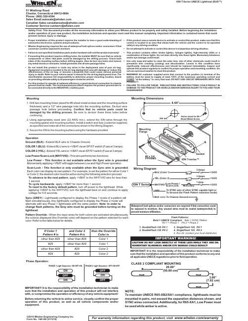
Safety First: This document provides all the necessary information to allow your Whelen product to be properly and safely installed. Before beginning the installation and/or operation of your new product, the installation technician and operator must read this manual completely. Important information is contained herein that could prevent serious injury or damage.•Proper installation of this product requires the installer to have a good understanding of automotive electronics,systems and procedures.•Whelen Engineering requires the use of waterproof butt splices and/or connectors if that connector could be exposed to moisture.•Failure to use specified installation parts and/or hardware will void the product warranty!•If mounting this product requires drilling holes,the installer MUST be sure that no vehicle components or other vital parts could be damaged by the drilling process.Check both sides of the mounting surface before drilling begins.Also de-burr any holes and remove any metal shards or remnants.Install grommets into all wire passage holes.•Do not install this product or route any wires in the deployment area of your air bag.Equipment mounted or located in the air bag deployment area will damage or reduce the effectiveness of the air bag,or become a projectile that could cause serious personal injury or death.Refer to your vehicle owner's manual for the air bag deployment area.The User/Installer assumes full responsibility to determine proper mounting location,based on providing ultimate safety to all passengers inside the vehicle.•For this product to operate at optimum efficiency,a good electrical connection to chassis ground must be made.The recommended procedure requires the product ground wire to be connected directly to the NEGATIVE (-)battery post.•If this product uses a remote device to activate or control this product,make sure that this control is located in an area that allows both the vehicle and the control to be operated safely in any driving condition.•Do not attempt to activate or control this device in a hazardous driving situation.•This product contains either strobe light(s),halogen light(s),high-intensity LEDs or a combination of these lights.Do not stare directly into these lights.Momentary blindness and/or eye damage could result.•Use only soap and water to clean the outer e of other chemicals could result in premature lens cracking (crazing)and discoloration.Lenses in this condition have significantly reduced effectiveness and should be replaced immediately.Inspect and operate this product regularly to confirm its proper operation and mounting condition.Do not use a pressure washer to clean this product.•WARNING!All customer supplied wires that connect to the positive (+)terminal of the battery must be sized to supply at least 125%of the maximum operating current and FUSED “at the battery”to carry that load.DO NOT USE CIRCUIT BREAKERS WITH THIS PRODUCT!•FAILURE TO FOLLOW THESE PRECAUTIONS AND INSTRUCTIONS COULD RESULT IN DAMAGE TO THE PRODUCT OR VEHICLE AND/OR SERIOUS INJURY TO YOU AND YOUR PASSENGERS!ION T-Series UNECE Lighthead (DUO™)©2016 Whelen Engineering Company Inc.Form No. 14A14D (011218)For warranty information regarding this product, visit /warrantyMounting DimensionsMounting1.Drill two mounting holes (sized for #6sheet metal screws and the mounting surface thickness)and a 1/2"wire passage hole into the mounting surface.De-burr wire passage hole before proceeding.Confirm that no vehicle parts could be damaged by the drilling process.Be sure to de-burr these three holes before continuing.ing appropriately sized wire (22AWG min.),extend the ION wires through the mounting gasket and mounting surface.Install a switch and fuse (customer supplied)as specified and make all of the connections shown in the Wiring Diagram.3.Secure the ION to the mounting surface using the hardware provided.PHASE 1 Light Sequence: ON-OFF-ON PHASE 2 Light Sequence: OFF-ON-OFFOperationGround (BLK) -Extend BLK wire to Chassis Ground.COLOR 1(BLU)-Extend BLU wire to +VBAT via an SP/ST switch (Fuse at 3amps).COLOR 2(YEL)-Extend YEL wire to +VBAT via an SP/ST switch (Fuse at 3amps).Low Power/Scan-Lock (WHT/VIO)-This wire performs two functions:Low Power -This function is not available when the Sync wire is grounded.Momentarily applying +VBAT will toggle between Low and High Power operation.Scan-Lock -This function is only available when the Sync wire is grounded.Each color can display its own pattern.For example,to set the pattern for either Color 1or Color 2,the desired color must be active during the following selection process:To advance to the next pattern , apply +VBAT to the WHT/VIO wire for less than 1 second., apply +VBAT for more than 1 second.To cycle backwards To reset to the factory default pattern , turn off power to the lighthead. While applying +VBAT to the WHT/VIO, turn the lighthead back on and continue to apply voltage for 5-6 seconds.Sync (GREY) -Lightheads configured to display the Phase 1 mode of a pattern will flash simultaneously.Any lightheads configured to display the Phase 2 mode will alternate with any Phase 1 lightheads with the same pattern.Note: In order to change flash patterns, the Grey wire must be grounded before turning on the lighthead.Pattern Override -When the input wires for both colors are activated simultaneously,the color(s)displayed (the Override color)will depend on the pattern selected for each color.Refer to the table below for details.Phase Operation:or If Color 1Pattern # is #29#29#29and Color 2Pattern # is other than #29other than #29other than #29other than #29#29then the OverrideColor isColor 1Color 1Color 2Color 2IMPORTANT!It is the responsibility of the installation technician to make sure that the installation and operation of this product will not interfere with,or compromise the operationor efficiency of any vehicle equipment!Before returning the vehicle to active service,visually confirm the proper operation of this product,as well as all vehicle components and/or equipment.Waterproof butt splices and/or connectors are required if that connection could be exposed to moisture.Any unused wires must be sealed (waterproofed)to prevent moisture infiltration.IMPORTANT!It isthe responsibility of the installation technician to make sure that the installation and operation of this product conforms to any and all applicable UNECE regulations prior to field operation.1.DoubleFlash 125PH 12.DoubleFlash 125PH 23.SingleFlash 125PH 14.SingleFlash 125PH 25.thru 29. (contact your local distributor)Flash Patterns:Italic = SYNC PatternBold = UNECE Compliant PH 1 = Phase 1 PH 2 = Phase 220.00”CLASS 2 COMPLIANT MOUNTINGNOTE:To maintain UNECE R65-XB2/XA1compliance,lightheads must be mounted in pairs,not exceed the separation distances shown,and SYNC wires connected.Additionally,for R65-XA1,Low Power must be used while amber is active.®ENGINEERING COMPANY INC.51 Winthrop RoadChester, Connecticut 06412-0684Phone: (860) 526-9504SalesEmail:*******************CanadianSales:************************CustomerService:*******************www..comWarnings to InstallersWhelen’s emergency vehicle warning devices must be properly mounted and wired in order to be effective and safe. Read and follow all of Whelen’s written instructions when installing or using this device. Emergency vehicles are often operated under high speed stressful conditions which must be accounted for when installing all emergency warning devices. Controls should be placed within convenient reach of the operator so that he can operate the system without taking his eyes off the roadway. Emergency warning devices can require high electrical voltages and/or currents. Properly protect and use caution around live electrical connections.Grounding or shorting of electrical connections can cause high current arcing, which can cause personal injury and/or vehicle damage, including fire. Many electronic devices used in emergency vehicles can create or be affected by electromagnetic interference.Therefore, after installation of any electronic device it is necessary to test all electronic equipment simultaneously to insure that they operate free of interference from other components within the vehicle. Never power emergency warning equipment from the same circuit or share the same grounding circuit with radio communication equipment.All devices should be mounted in accordance with the manufacturer’s instructions and securely fastened to vehicle elements of sufficient strength to withstand the forces applied to the device. Driver and/or passenger air bags (SRS) will affect the way equipment should be mounted.This device should be mounted by permanent installation and within the zones specified by the vehicle manufacturer, if any.Any device mounted in the deployment area of an air bag will damage or reduce the effectiveness of the air bag and may damage or dislodge the device. Installer must be sure that this device, its mounting hardware and electrical supply wiring does not interfere with the air bag or the SRS wiring or sensors. Mounting the unit inside the vehicle by a method other than permanent installation is not recommended as unit may become dislodged during swerving; sudden braking or collision. Failure to follow instructions can result in personal injury. Whelen assumes no liability for any loss resulting from the use of this warning device. PROPER INSTALLATION COMBINED WITH OPERATOR TRAINING IN THE PROPER USE OF EMERGENCY WARNING DEVICES IS ESSENTIAL TO INSURE THE SAFETY OF EMERGENCY PERSONNEL AND THE PUBLIC.Warnings to UsersWhelen’s emergency vehicle warning devices are intended to alert other operators and pedestrians to the presence and operation of emergency vehicles and personnel. However, the use of this or any other Whelen emergency warning device does not guarantee that you will have the right-of-way or that other drivers and pedestrians will properly heed an emergency warning signal. Never assume you have the right-of-way. It is your responsibility to proceed safely before entering an intersection, driving against traffic, responding at a high rate of speed, or walking on or around traffic lanes. Emergency vehicle warning devices should be tested on a daily basis to ensure that they operate properly. When in actual use, the operator must ensure that both visual and audible warnings are not blocked by vehicle components (i.e.: open trunks or compartment doors), people, vehicles, or other obstructions. It is the user’s responsibility to understand and obey all laws regarding emergency warning devices.The user should be familiar with all applicable laws and regulations prior to the use of any emergency vehicle warning device. Whelen’s audible warning devices are designed to project sound in a forward direction away from the vehicle occupants. However, because sustained periodic exposure to loud sounds can cause hearing loss, all audible warning devices should be installed and operated in accordance with the standards established by the National Fire Protection Association.。
HIRSCHMANN中文产品使用手册RS系统工业以太网交换机

1.1.1 1.1.2 1.1.3 1.1.4 1.1.5
RS20/RS30 组合选项.........................................................................................................11 RS40 组合选项...............................................................................................................1514 RS20-…端口数量和端口介质类型.................................................................................1615 RS30-…端口数量和端口介质类型.................................................................................1817 RS40-…端口数量和端口介质类型.................................................................................2019
用户手册
安装 工业以太网卡轨式交换机 RS20/RS30/RS40 系列
24 端口 RS20
9 端口 RS20
8 端口 RS20
4 端口 RS20
18 端口 RS30
RS20/RS30/RS40
发布日期:02/07
10 端口 RS30
9 端口 RS40
技术支持
HAC-Support@hirschmann.de
Avaya S8400 安装配置手册中文版R1.1 CM4

Avaya S8400安装配置手册中文版 R1.12007年5月适用于CM4.0第一章系统介绍 (4)第一节使用对象 (4)第二节准备工作 (4)第三节S8400媒体服务器(TN8400AP) (4)第四节S8400媒体服务器IP接口电路板(TN8412AP SIPI) (7)第五节G650媒体网关 (10)(一)技术规格 (10)第六节G650中常用电路板(TN)系列 (11)(一)TN2464CP数字中继板 (12)(二)TN429D 8路模拟中继板 (12)(三)TN2214CP 24路数字分机板 (13)(四)TN793CP24路模拟分机板 (14)(五)TN799DP 控制局域网接口板 (14)(六)TN2302AP IP 媒体处理器板 (15)(七)TN2501AP 局域网上的语音通知板 (16)(八)TN771DP 维护与测试板 (16)(九)TN744E 呼叫分类器与音频检测器板 (17)第二章安装硬件 (18)第一节安装步骤: (18)第二节G650安装 (18)(一)柜门拆卸 (18)(二)机架安装 (20)(三)机层地址设置 (20)(四)电源模块振铃开关设置 (26)(五)安装电路板 (28)(六)安装适配器 (29)(七)S8400媒体服务器安装 (29)第三节配线系统 (31)(一)25对电缆线序图 (31)(二)TN2464CP数字中继板线序图 (31)(三)TN429D 8路模拟中继板线序图 (31)(四)TN2214CP 24路数字分机板和TN793CP 24路模拟分机板线序图 . 32第三章如何登入系统 (32)第一节访问方式 (32)(一)直接访问 (32)(二)远程访问方式 (33)第二节维护软件 (33)(一)通用软件 (34)(二)专用软件 (34)第三节系统用户名和密码 (39)(一)初始化 (40)(二)安装完许可文件后初次录 (40)第四章安装操作系统和语音通信应用软件 (40)第五章配置媒体服务器 (41)第六章配置SIPI和CLAN卡 (45)第一节配置SIPI卡 (45)第二节配置CLAN卡 (47)第三节配置MED-PRO卡 (49)第七章安装确认测试系统 (49)第八章设置拨号方案表 (50)第九章设置分机 (52)第一节模拟分机 (52)第二节数字分机 (52)第三节IP硬电话 (52)第四节IP软电话 (53)第十章设置中继 (53)第一节模拟中继 (53)第二节数字中继 (54)第三节IP中继 (57)第十一章设置去话分析 (57)第十二章设置来话分析 (58)第一节BID (58)第二节DID (59)第十三章话机常用功能设置 (59)第一节转接电话 (59)第二节会议电话 (59)第三节热线电话 (61)第四节缩位拔号 (61)第五节代接 (61)第六节呼叫转移 (61)第十四章设置计费 (61)第十五章设置语音邮箱 (62)附录一常用命令 (71)附录二参考文档 (71)第一章系统介绍第一节使用对象本手册适用于具备一定语音数字程控交换机、计算机网络和VoIP基础知识的技术工程师,学习安装配置S8400。
诺德士脚踏车安装手册说明书

(诺德士)安装手册/用户手册2重要安全说明 3 安全警报标签/序列号 4规格 5安装前 5部件 6配件 7工具 7安装 8水平放置脚踏车 14移动脚踏车 14功能 15 控制台功能 16 Bluetooth ® 连接功能 19 远程心率监测 20操作 22调整 22 初始设置 23 快速开始/手动方案 23 用户概要文件 23 概要方案 25 暂停或停止 28 结果 28 目标跟踪统计数据 29控制台设置模式 30维护 31 维护部件 32检修 33Nautilus, Inc., | Nautilus, Inc., 18225 NE Riverside Parkway, Portland ,或者 97230 USA | © 2017 Nautilus, Inc. ® 是指在美国的注册商标。
这些标志可能在其他国家注册或者受习惯法的保护。
Nautilus (诺德士)、Nautilus 标志、 Nautilus Trainer 、Bowflex (搏飞)、Schwinn ,和 Universal 是 Nautilus, Inc. 拥有或获许可的商标。
Polar ®、OwnCode ®、iTunes ®、 Google Play™、Under Armour ®、MyFitnessPal ® 和 RideSocial™ 是其各自所有人的商标。
Bluetooth ® 字标和标志是 Bluetooth SIG, Inc. 拥有的注册商标,Nautilus, Inc. 已获得授权使用任何此类标志。
原版手册 - 仅限英文版本为获得保修服务,请妥善保存原始购买证明并填写以下信息:序列号 __________________________购买日期 ____________________为登记您的产品保修,请联系您当地的经销商。
阿里斯自动车辆产品安装说明书

INSTALLATION MANUAL1110313MaintenanceTo protect the product, wax after installing. Regular waxing is recommended to add a protective layer over the finish. Do not use any type of polish or wax that may contain abrasives that could damage the finish.For polished, gloss and other smooth finishes, polish may be used to clear small scratches and scuffs on the finish.Mild automotive detergent may be used to clean the product. Do not use dish detergent, abrasive cleaners, abrasive pads, wire brushes or other similar products that may damage the finish.Product PhotoEasy NOTICE Before you begin installation, read all instructions thoroughly.Proper tools will improve the quality of installation and reduce the time required.To help prevent damage to the product or vehicle, refer to the specifiedtorque specifications when securing hardware during the installation process.Product Registration and Warranty CURT Group stands behind our products with industry-leading warranties. Provide feedback and help us to improve our products by registering your purchase at: /surveysStarting on the driver side, locate the mounting points on the vehicle.Remove any existing hardware. Step 2On the side attachment, use a 5/8" spacer, an M8 bolt, lock washer and flat washer tosecure the bracket to the vehicle. Step 3On the top attachment, use a 5/8" spacer, a 1/2" spacer, two M6 bolts, lock washers and flat washers to secure the bracket to the vehicle. Repeat steps 2 through 3 on thepassenger side of the vehicle.5/8" spacerM6 boltM6 lockwasherM6 flatwasher1/2" spacer5/8" spacerM8 lock washerM8 boltM8 flat washerStep 5Congratulations on the installation of your new ARIES LED light bar brackets.With the brackets installed, periodic inspections should be performed to ensure all mounting hardware remains tight.To protect your investment, see the'Notes and Maintenance' section on page one.To install a 50" LED light bar (part# 1501278 - sold separately), use two 1/4" carriage bolts, flat washers and nylock nuts per side at eachmounting location.。
Eaton RS Enclosure 设备轨道安装说明说明书

RS Enclosure rail installationOpen levers Closed levers Rail position adjustmentTo reposition an equipment rail,1. Flip open two blue cam levers.2. Slide equipment rail forward or back to desired position.3. Align diamond cutout on rail with desired hash marks on enclosure’s side members (hash mark spacing is 10 mm, or approximately 3⁄8").4. Ensure that rail is aligned vertically.5.Flip the cam levers to the locked position.This instruction sheet covers methodsrequired to move, adjust and operateequipment rails within the Eaton RSEnclosure.On heavy loads, 1. Use Rail Set Screw kit # RSRLKIT , to secure and lock position of rails, prior to loading cabinet.800 mm wide - mount to inner rail channelsRemoving an equipment rail 1. Flip open two blue camlevers.2. Tilt top of rail forward orback to unseat rails hangerbrackets;3. lift and remove rail fromenclosure’s side members.Installing cage nuts*1. Cage nuts must be installed horizontally into equipmentrail’s square holes with retention ears engaging verticalsides of square holes.* A clip nut that is installed vertically will not engageproperly and is in danger of falling out of square hole.2. Cage nuts must be installedinto rear face of equipment rail,opposite equipment mounting face.3. Angle cage nut into square hole, engaging one ofits retention ears. Use a cage nut installation toolto grab remaining retention ear, pulling cage nutfully into square hole.Rails come in two versions, standard square holes andtapped 12-24 holes. Hardware kits of cage nuts and screwsare provided to facilitate mounting of equipment.Rail system kits and contentsKit M6 Hardware, V3CAGEMKit 12-24 Hardware, JHK1224Eaton1000 Eaton Boulevard Cleveland, OH 44122 United States © 2016 EatonAll Rights Reserved Printed in USA Publication No. IL159006EN June 2016Eaton is a registered trademark. All trademarks are propertyof their respective owners.DISCLAIMER OF WARRANTIES AND LIMITATION OF LIABILITYThe information, recommendations, descriptions and safety notations in this document are based on Eaton Corporation’s (“Eaton”) experience and judgmentand may not cover all contingencies. If further information is required, an Eaton sales office should be consulted. Sale of the product shown in this literature issubject to the terms and conditions outlined in appropriate Eaton selling policies or other contractual agreement between Eaton and the purchaser.THERE ARE NO UNDERSTANDINGS, AGREEMENTS, WARRANTIES, EXPRESSED OR IMPLIED, INCLUDING WARRANTIES OF FITNESS FOR A PARTICULARPURPOSE OR MERCHANTABILITY, OTHER THAN THOSE SPECIFICALL Y SET OUT IN ANY EXISTING CONTRACT BETWEEN THE PARTIES. ANY SUCHCONTRACT STATES THE ENTIRE OBLIGATION OF EATON. THE CONTENTS OF THIS DOCUMENT SHALL NOT BECOME PART OF OR MODIFY ANYCONTRACT BETWEEN THE PARTIES.In no event will Eaton be responsible to the purchaser or user in contract, in tort (including negligence), strict liability or otherwise for any special, indirect,incidental or consequential damage or loss whatsoever, including but not limited to damage or loss of use of equipment, plant or power system, cost of capital, loss of power, additional expenses in the use of existing power facilities, or claims against the purchaser or user by its customers resulting from the use of theinformation, recommendations and descriptions contained herein. The information contained in this manual is subject to change without notice.RS Rack Rail inStallationFollow us on social media to get thelatest product and support information.。
导轨安装手册-中文

导轨安装手册-中文目录1装配指导的相关内容1.1功能和有效性1.2目标群1.3所使用的符号行动注意事项警告信息1.4其他说明MONORAIL装配指导描述了如何装配导轨系统MONORAILMR和MONORAILBMSCHNEEBERGER确定了以下的客户群:产品制造商产品用户机床制造商是SCHNEEBERGER.的直接客户。
制造商将SCHNEEBERGER 系统安装在其机床中并将成品出售给最终用户。
本装配指导主要提供给机床制造商供其使用。
→单步骤行动1.多步骤行动中的第一步。
注:这些是信息和建议。
警报信息出现在可能导致危险的步骤之前。
其有以下几种形式:信号如果忽视警告信息的后果。
→防止损坏或者伤害的措施。
警告信息分成以下几个类别:警告这表示如果没有采取规定的预防措施,则存在人员受到严重伤害或者材料受到重大损坏的危险。
注意这表示如果没有采取规定的预防措施,则存在人员受到轻微伤害或者材料受到轻微损坏的危险。
MONORAIL产品目录2安全注意事项2.1授权人员2.2正确使用2.3一般安全和防护措施仓储装配维修其他2.4环保只能由经过培训的专业人员来安装MONORAIL。
例如,已阅读并了解此装配指导的装配工。
MONORAIL主要用于机床和特殊设备设计的精密直线运动。
MONORAIL只能在规定的温度范围内使用。
确保滑块轴承没有受到侵蚀性物质等的损坏。
在安装之前MONORAIL必须一直贮藏于原包装中以防潮及防止损坏。
在安装期间,所有组件均必须置于相同的室温中。
维修时只能使用SCHNEEBERGER原装零件。
必须遵守有关安全预防的国家规定、标准和指令。
如果未经许可对MONORAIL进行修改,则由此而引起的损坏SCHNEEBERGER概不负责。
润滑油不得溢出,以环保的方式处理润滑油。
3描述3.1产品类型3.2组件MONORAIL系统横截面MONORAIL是一个导向系统。
MONORAIL由一根承载滑块的单导轨(MONORAIL导轨)或者几根配套的MONORAIL导轨组成。
- 1、下载文档前请自行甄别文档内容的完整性,平台不提供额外的编辑、内容补充、找答案等附加服务。
- 2、"仅部分预览"的文档,不可在线预览部分如存在完整性等问题,可反馈申请退款(可完整预览的文档不适用该条件!)。
- 3、如文档侵犯您的权益,请联系客服反馈,我们会尽快为您处理(人工客服工作时间:9:00-18:30)。
RM开关 STBY开关 环网 Coupling 环网管理 环网端口 控制线端口 Coupling端口 开关 开关 端口 OFF ON OFF ON OFF OFF ON ON on on on off off off on off off on off off DIP 2 DIP 2 DIP 2 1.3(MS20) 2.3(MS30) 1.4(MS20) 2.4(MS30)
安装扩展底板须拆卸底板右侧固定螺丝(上下各一个) 安装扩展底板须拆卸底板右侧固定螺丝(上下各一个) 移除保护档板 为防止受力不均损坏产品,应先将底板与扩展底板分别安装至导轨后, 为防止受力不均损坏产品,应先将底板与扩展底板分别安装至导轨后,沿导轨 缓慢推动完成底板衔接。 缓慢推动完成底板衔接。 拧紧固定螺丝,固定扩展底板。 拧紧固定螺丝,固定扩展底板。
DIP开关 开关
4针端子排 针端子排
Power 2
Power MICE DIP开关 开关
DIP 1 OFF: : ON: : DIP 2 关闭冗余管理 开启冗余管理
1 2 3 4 5 6 RM Ring Port Stand-by HIPER-Ring - DIP ON Service
OFF: 环网端口 : 环网端口1.1+1.2 ON: 环网端口2.1+2.2 环网端口 非Stand-by状态 状态 Stand-by状态 状态 关闭环网功能 关闭RSTP 关闭 DIP开关失效 开关失效 DIP开关生效 开关生效
光纤连接: 光纤连接: 需确认接口类型一致,收发对应正确。 需确认接口类型一致,收发对应正确。
RS交换机 交换机LED状态显示 交换机 状态显示
P-电源 电源LED: 电源 : 绿色- 绿色-供电正常 黄色- 黄色-单路电源供电 熄灭- 熄灭-电压过低 FAULT-故障 故障LED: 故障 红色- 红色-信号触点有输出 熄灭- 熄灭-信号触点无输出 RM-冗余状态 冗余状态LED: 冗余状态 绿色-环网管理生效,环网无断点 绿色-环网管理生效, 黄色-环网管理生效, 黄色-环网管理生效,环网断开 熄灭- 熄灭-环网管理关闭 闪烁- 闪烁-错误的环网配置
直流接线
交流接线
缺省时,如下情况 、 接线柱输出故障信息 缺省时,如下情况2、5接线柱输出故障信息 至少一路电压低于9.6V 至少一路电压低于 内部电压问题造成的故障 至少一个端口连接状态异常 环网断开与恢复
RS交换机线缆连接 交换机线缆连接
1、2号端口为环网连接端口。 、 号端口为环网连接端口 号端口为环网连接端口。
4 3 2 1
24V DC
MS交换机 交换机LED状态显示 交换机 状态显示
设备LED 用于检测设备运行状态 设备
端口LED 配合显示 配合显示LED检测端口信息 端口 检测端口信息
显示LED 显示当前端口 显示当前端口LED显示信息的内容 显示 显示信息的内容 通过按住Select按钮 按钮 通过按住 切换显示LED位置 切换显示 位置
1、2号端口 、 号端口
DIP开关 开关
3-n号端口 - 号端口
USB接口 接口
地址栏
V.24接口 接口
RS交换机安装与拆卸 交换机安装与拆卸
35mmDIN轨安装 轨安装 前面板螺丝用于接地
卡槽上沿卡入导轨后用 力下压
螺丝刀顶住弹簧片孔后 下拉,取下交换机。 下拉,取下交换机。
RS交换机电源接线 交换机电源接线
双绞线连接: 双绞线连接: 一般情况下,设备出厂时除环网端口, 一般情况下,设备出厂时除环网端口,其他端口默认开启自适应功能 交换机之间使用交叉线,交换机到终端设备间使用平行线。 交换机之间使用交叉线,交换机到终端设备间使用平行线。 由于自交叉功能,除环网、环间耦合用到的连接线可以调整平行线线序。 由于自交叉功能,除环网、环间耦合用到的连接线可以调整平行线线序。
OpenRail安装与配置简介 安装与配置简介
上海海得控制系统股份有限公司 2008年 网络部 2008年1月
RS交换机外观 交换机外观
RS20-0400
RS20-0800
RS20-1600
RS20-2400
RS30-0802
ห้องสมุดไป่ตู้
RS30-1602
RS30-2402
RS交换机外观 交换机外观
6针端子排 针端子排 LED显示 显示
MS交换机外观 交换机外观
MS20-0800
MS30-0800
MS20-1600
MS30-1600
MS交换机外观 交换机外观
GE模块插槽 模块插槽 FE模块插槽 模块插槽
LED显示 显示
选择按键 Slot 1 Slot 2 Slot 3 Slot 4 Slot 5 Slot 6 Slot 7
MS交换机外观 交换机外观
模块号].[端口号] ].[端口号 端口编号 [模块号].[端口号] 1.1-1.4 - 2.1-2.4 - LED显示 显示 FE模块插槽 模块插槽
选择按键 Slot 1 Slot 2 Slot 3 Slot 4 Slot 5 Slot 6
MS交换机外观 交换机外观
V.24接口 接口
USB接口 接口
直流供电:正极连接 、 直流供电:正极连接1、 6接线柱,负极连接 、 接线柱, 接线柱 负极连接3、 4接线柱。 接线柱。 接线柱
交流供电:连接 、 、 交流供电:连接1、3、 4、6。 、 。 故障信号: 故障信号: 单路电源供电时, 单路电源供电时,交换 指示灯亮, 机FAULT指示灯亮, 指示灯亮 有报警输出, 有报警输出,使用软件 关闭交换机电源报警或 短接1、 接线柱 接线柱。 短接 、6接线柱。
MS交换机 交换机LED状态显示 交换机 状态显示
P-电源 电源LED: 电源 : 绿色- 绿色-内部供电正常 熄灭- 熄灭-电压过低 P1/P2-电源 电源1/2LED: 电源 绿色- 绿色-该路电源供电正常 熄灭-该路电源低于 熄灭-该路电源低于18V RM-冗余状态 冗余状态LED: 冗余状态 绿色-环网管理生效, 绿色-环网管理生效,环网无断点 黄色-环网管理生效,环网断开 黄色-环网管理生效, 熄灭- 熄灭-环网管理关闭 闪烁- 闪烁-错误的环网配置 R1/R2-信号触点 信号触点LED: 信号触点 : 红色-故障信号触点输出, 红色-故障信号触点输出,故障报警 黄色-故障信号触点输出, 黄色-故障信号触点输出,人工定义 熄灭- 熄灭-故障信号触点关闭 RUN-运行 启动 运行/启动 运行 启动LED: 绿色-设备系统就位, 绿色-设备系统就位,正在运行 黄色- 黄色-设备系统正在启动过程 熄灭- 熄灭-设备系统重启
MS交换机电源接线 交换机电源接线
正极连接1接线柱 正极连接 接线柱 负极连接2接线柱。 负极连接 接线柱。 接线柱 1 2 3 4 1 2 3 4 48V DC 1 2 3 4
单路电源供电时,交换机 指示灯亮 指示灯亮, 单路电源供电时,交换机RL指示灯亮, 有报警输出, 有报警输出,使用软件关闭交换机电源报 警或短接两路电源正极。 警或短接两路电源正极。 缺省时,如下情况 、 接线柱输出故障信息 缺省时,如下情况3、4接线柱输出故障信息 至少一路电压低于18V 至少一路电压低于 内部电压问题造成的故障 至少一个端口连接状态异常 环网断开与恢复 Coupling控制线短接,Coupling功能启动 控制线短接, 控制线短接 功能启动
DIP 3
OFF: ON:
DIP 4
OFF: ON: :
DIP 5
OFF: ON: :
DIP 6
OFF: 普通模式 : ON: : 工程维修模式
交换机简单配置
IP地址分配 地址分配
超级终端连接以CLI方式进行配置 方式进行配置 超级终端连接以 – 使用终端电缆连接交换机 使用终端电缆连接交换机V.24端口和 机COM口 端口和PC机 端口和 口 – 使用 使用Windows附件 附件——超级终端模拟 超级终端模拟VT100 附件 超级终端模拟 – 连接配置: 连接配置: Speed 9600Baud Data 8Bit Parity none Stopbit 1 Handshake off 或直接还原Windows默认值 或直接还原 默认值
RS交换机 交换机LED状态显示 交换机 状态显示
by-耦合状态LED LED: Stand by-耦合状态LED: 绿色- 绿色-耦合冗余状态 熄灭- 熄灭-非耦合冗余状态
LS-连接状态LED: LS-连接状态LED: 熄灭- 熄灭-无有效物理连接 绿色- 绿色-当前端口有一个有效物理连接 慢闪- 慢闪-端口处于冗余状态 快闪- 快闪-端口被禁闭 DA-数据状态LED: DA-数据状态LED: 熄灭- 熄灭-无数据传输 黄色- 黄色-正在进行数据传输
MS交换机 交换机LED状态显示 交换机 状态显示
显示LED通常位于 通常位于L/D状态,按住 状态, 显示 通常位于 状态 按住Select键2秒可在各状态间进行 键 秒可在各状态间进行 切换 Select无操作 秒,显示 无操作2秒 显示LED恢复 恢复L/D状态 无操作 恢复 状态 各状态LED为绿色分别代表正在检查端口 为绿色分别代表正在检查端口LED的相应状态 各状态 为绿色分别代表正在检查端口 的相应状态
MS交换机 交换机DIP开关 交换机 开关
机型 MS20 MS20 MS30 MS30 DIP 2 OFF ON OFF ON 环网端口1 环网端口2 环网端口 环网端口 1.1 1.1 1.1 2.1 1.2 2.1 1.2 2.1
DIP 4位于 位于OFF时所有 时所有DIP 位于 时所有 失效, 失效,改由软件进行配置
L/D: : FDX:
连接/数据检测 连接 数据检测 双工通讯检测
AN: RING:
自适应端口检测 环网端口检测
1000: 传输速率检测 :
