MCS407
计算机发展通史 第三讲现代计算机的发展

Willamette处理器外观 处理器外观 1.3g-2g 1998年3月,Intel公司在 CeBIT贸易博览会展出 了一种速度高达702MHz 的奔腾II芯片。1999年, 以奔腾II450、奔腾III450 为微处理器、内存 128MB、硬盘8.4GB的 微机已在我国上市。至 2000年11月,Intel发布 采用第七代Netburst微 架构的Pentium 4处理器
几大公司的发展
Ibm公司的发展 Microsoft公司的发展 Intel公司的发展
计算机发展通史
第三讲 现代计算机的发展 主讲人:王锋
微型计算机的发展
微型计算机大致经历了四个阶段: 第一阶段是1971~1973年,微处理器有4004、 4040、8008。 1971年Intel公司研制出MCS4 微型计算机(CPU为4040,四位机)。后来又 推出以8008为核心的MCS-8型。 第二阶段是1973~1977年,微型计算机的发 展和改进阶段。微处理器有8080、8085、 M6800、Z80。初期产品有Intel公司的MCS一 80型(CPU为8080,八位机)。后期有TRS80型(CPU为Z80)和APPLE-II型(CPU为 6502),在八十年代初期曾一度风靡世界。
IBM公司“深蓝“电脑击败了人类的世界 国际象棋冠军,美国制定了以多Agent系统应 用为重要研究内容的信息高速公路计划,基于 Agent技术的Softbot(软机器人)在软件领域和 网络搜索引擎中得到了充分应用,同时,美国 Sandia实验室建立了国际上最庞大的“虚拟现 实“实验室,拟通过数据头盔和数据手套实现 更友好的人机交互,建立更好的智能用户接口。 图像处理和图像识别,声音处理和声音识别取 得了较好的发展,IBM公司推出了ViaVoice声 音识别软件,以使声音作为重要的信息输入媒 体。国际各大计算机公司又开始将“人工智能 “作为其研究内容。人们普遍认为,计算机将 会向网络化、智能化、并行化方向发展。二十 一世纪的信息技术领域将会以智能信息处理为 中心。
Si55xx-EB 用户指南说明书

UG444: Si55xx Evaluation Board User's GuideThe Si55xx-EB is used for evaluating Si5518, Si5512, Si5510 andSi5508 Low Phase Noise Jitter Attenuating Clocks, which can beused for 5G/eCPRI/SyncE/IEEE 1588 applications. The Si5518 com-bines a high-performance JESD204B/C compatible RF clock jitterattenuator and two fifth-generation DSPLLs supporting SyncE/IEEE1588 network synchronization. All the Si55xx devices support up tosix inputs. The Si5518/10/08 all have 18 differential outputs while theSi5512 has 12 differential outputs. The Si55xx-A-EB should be usedin conjunction with Skyworks’ ClockBuilder™ Pro software.This document is intended for all Si55xx-A-EVB product variants which includes Si5518,Si5512, Si5510 and Si5508. The exact device and revision is distinguished by a white 1x 0.187 inch label underneath the board’s silkscreen name. The Si5518 device is installedon the evaluation board and will be used for evaluation purposes of any of the productvariants. ClockBuilder Pro software is used to select the specific product variant to beevaluated (Si5518/10/08). The "Si5518-A-EB" label indicates that the evaluation board hasbeen assembled with an Si5518 device, Revision A, installed. Strictly for ordering purposes,the terms “EB” and “EVB” refer to the board and kit, respectively. In this document, the terms are synonymous.KEY FEATURES •Si55xx-A-EVB used with ClockBuilder Pro software to evaluate Si5518,Si5512, Si5510, Si5508•Powered from USB port and an external power supply, via either a screw terminal connector or a compatible wall-mounted ac adapter •Onboard 54 MHz low phase noise XO and a 54 MHz crystal •Layout provisions for select VCXO and XTAL components •ClockBuilder Pro GUI-programmable VDD supply supports device core voltages of 3.3 V and 1.8 V •ClockBuilder Pro GUI-programmable VDDO supplies allow each of the outputs to have its own power supply voltage selectable from 3.3 V, 2.5 V, or 1.8 V •ClockBuilder Pro GUI-controlled voltage, current, and power measurements of VDD and all VDDOsupplies•Status LEDs for power supplies andcontrol/ status signals of the Si55xxdevice•SMA connectors for input clocks,output clocks, optional externalreference, and optional VCNTRL•EVB board modifications for Low-Power ModeSkyworksSolutions,Inc.•Phone[781]376-3000•Fax[781]376-3100•*********************• Skyworks Proprietary Information • Products and Product Information are Subject to Change Without Notice • June 29, 20221D o c u m e n t A v a i l a b l e U n d e r N D A C o n t a c t S k y w o r k s f o r A c c e s sCopyright © 2022 Skyworks Solutions, Inc. All Rights Reserved.Information in this document is provided in connection with Skyworks Solutions, Inc. (“Skyworks”) products or services. These materials, including the information contained herein, are provided by Skyworks as a service to its customers and may be used for informational purposes only by the customer. Skyworks assumes no responsibility for errors or omissions in these materials or the information contained herein. Skyworks may change its documentation, products, services, specifications or product descriptions at any time, without notice. Skyworks makes no commitment to update the materials or information and shall have no responsibility whatsoever for conflicts, incompatibilities, or other difficulties arising from any future changes.No license, whether express, implied, by estoppel or otherwise, is granted to any intellectual property rights by this document. Skyworks assumes no liability for any materials, products or information provided hereunder, including the sale, distribution, reproduction or use of Skyworks products, information or materials, except as may be provided in Skyworks’ Terms and Conditions of Sale.THE MATERIALS, PRODUCTS AND INFORMATION ARE PROVIDED “AS IS” WITHOUT WARRANTY OF ANY KIND, WHETHER EXPRESS, IMPLIED, STATUTORY, OR OTHERWISE, INCLUDING FITNESS FOR A PARTICULAR PURPOSE OR USE, MERCHANTABILITY, PERFORMANCE, QUALITY OR NON-INFRINGEMENT OF ANY INTELLECTUAL PROPERTY RIGHT; ALL SUCH WARRANTIES ARE HEREBY EXPRESSL Y DISCLAIMED. SKYWORKS DOES NOT WARRANT THE ACCURACY OR COMPLETENESS OF THE INFORMATION, TEXT, GRAPHICS OR OTHER ITEMS CONTAINED WITHIN THESE MATERIALS. SKYWORKS SHALL NOT BE LIABLE FOR ANY DAMAGES, INCLUDING BUT NOT LIMITED TO ANY SPECIAL, INDIRECT, INCIDENTAL, STATUTORY, OR CONSEQUENTIAL DAMAGES, INCLUDING WITHOUT LIMITATION, LOST REVENUES OR LOST PROFITS THAT MAY RESUL T FROM THE USE OF THE MATERIALS OR INFORMATION, WHETHER OR NOT THE RECIPIENT OF MATERIALS HAS BEEN ADVISED OF THE POSSIBILITY OF SUCH DAMAGE Skyworks products are not intended for use in medical, lifesaving or life-sustaining applications, or other equipment in which the failure of the Skyworks products could lead to personal injury, death, physical or environmental damage. Skyworks customers using or selling Skyworks products for use in such applications do so at their own risk and agree to fully indemnify Skyworks for any damages resulting from such improper use or sale.Customers are responsible for their products and applications using Skyworks products, which may deviate from published specifications as a result of design defects, errors, or operation of products outside of published parameters or design specifications. Customers should include design and operating safeguards to minimize these and other risks. Skyworks assumes no liability for applications assistance, customer product design, or damage to any equipment resulting from the use of Skyworks products outside of Skyworks’ published specifications or parameters.Skyworks, the Skyworks symbol, Sky5®, SkyOne®, SkyBlue™, Skyworks Green™, ClockBuilder®, DSPLL®, ISOmodem®, ProSLIC®, and SiPHY® are trademarks or registered trademarks of Skyworks Solutions, Inc. or its subsidiaries in the United States and other countries. Third-party brands and names are for identification purposes only and are the property of their respective owners. Additional information, including relevant terms and conditions, posted at , are incorporated by reference.SkyworksSolutions,Inc.|Nasdaq:SWKS|*********************| USA: 781-376-3000 | Asia: 886-2-2735 0399 | Europe: 33 (0)1 43548540Portfolio Quality /quality SW/HW /CBPro Support & Resources/support。
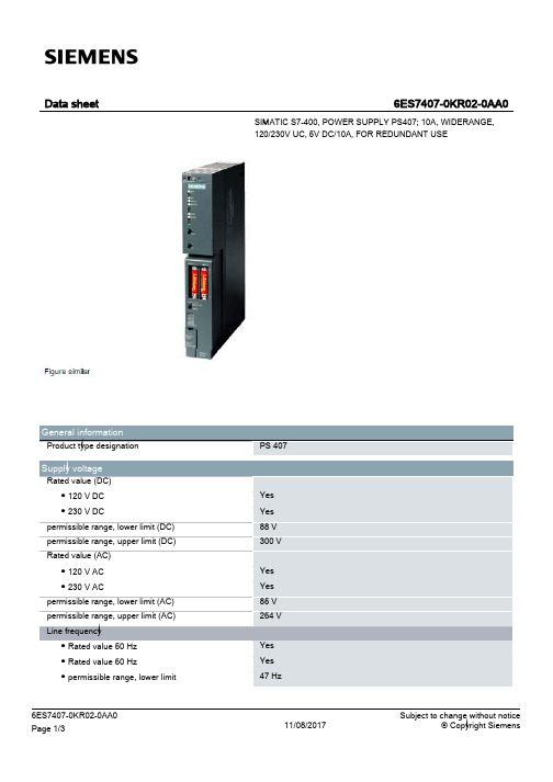
西门子SIMATIC S7-400电源407数据表,10A宽范围输出,120 230V交流,5V D
6ES7407-0KR02-0AA0 Page 2/3
11/08/2017
Subject to change without notice © Copyright Siemens
Standards, approvals, certificates FM approval
Ambient conditions Ambient temperature during operation ● min. ● max.
● Compliance with line harmonic distortion acc. to Yes IEC 61000-3-2, IEC 61000-3-3
Degree and class of protection Equipment protection class
I, with protective conductor
10 A; no base load required 1 A; idling-proof Yes
Power Active power input, typ.
95 W
Power loss Power loss, typ.
20 W
Battery Backup battery
● Backup battery (optional)
Connection method Connecting cables/cross-sections
Dimensions Width Height Depth
Weights Weight, approx.
last modified:
Yes; Ta: 0 °C to 70 °C T4
0 °C 60 °C
Subject to change without notice © Copyright Siemens
aod407场效应管参数

aod407场效应管参数AOD407是一种N通道增强型场效应管,其参数包括以下几个主要方面:1.最大漏极电压(UDSS):AOD407的最大漏极电压为100V,这意味着在正常工作时,漏极电压不应超过这个值。
如果实际电压超过这个值,可能会损坏场效应管。
2.最大功耗(PD):AOD407的最大功耗为150W,这意味着在使用过程中,场效应管产生的热量不应超过这个值。
如果实际功耗超过这个值,可能会导致场效应管过热甚至烧毁。
3.最大漏极电流(ID):AOD407的最大漏极电流为28A,这意味着在正常工作时,漏极电流不应超过这个值。
如果实际电流超过这个值,可能会损坏场效应管。
4.最大开关频率(fMAX):AOD407的最大开关频率为500kHz,这意味着在正常工作时,开关频率不应超过这个值。
如果实际开关频率超过这个值,可能会导致场效应管发热或损坏。
5.输入电容(CIN):AOD407的输入电容为8pF,这意味着在正常工作时,输入电容不应超过这个值。
如果实际输入电容超过这个值,可能会影响场效应管的开关速度和效率。
6.门极阈值电压(VGS):AOD407的门极阈值电压为2.5V,这意味着在正常工作时,门极电压不应低于这个值。
如果实际门极电压低于这个值,可能会导致场效应管无法正常导通。
7.导通电阻(RON):AOD407的导通电阻为0.012Ω,这意味着在正常工作时,导通电阻不应超过这个值。
如果实际导通电阻超过这个值,可能会影响场效应管的导通效率和热性能。
总之,AOD407是一种高性能的N通道增强型场效应管,具有较高的开关速度、低导通电阻和较低的输入电容等特点。
在使用过程中,需要注意其最大功耗、最大漏极电流、最大开关频率等参数,以确保场效应管的正常工作和可靠性。
同时,还需要注意其门极阈值电压和导通电阻等参数,以避免场效应管无法正常导通或导通效率低下等问题。
STM32F407通用定时器输入捕获
通用定时器输入捕获通用定时器作为输入捕获的使用。
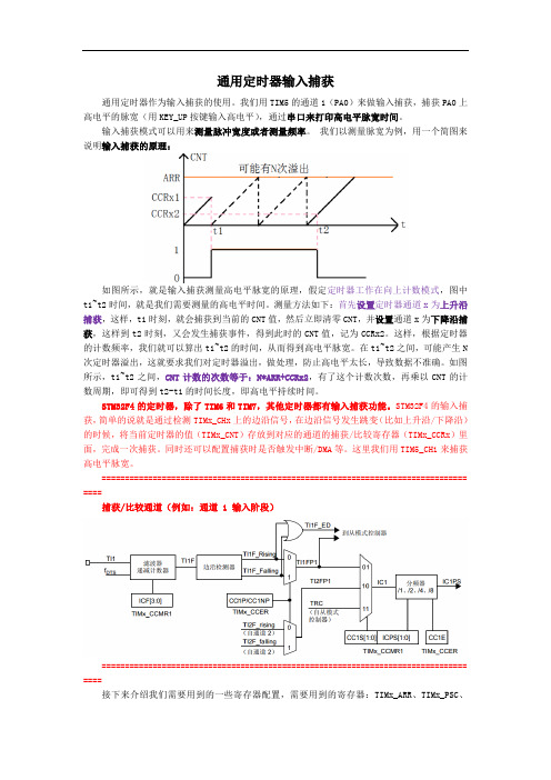
我们用TIM5的通道1(PA0)来做输入捕获,捕获PA0上高电平的脉宽(用KEY_UP按键输入高电平),通过串口来打印高电平脉宽时间。
输入捕获模式可以用来测量脉冲宽度或者测量频率。
我们以测量脉宽为例,用一个简图来说明输入捕获的原理:如图所示,就是输入捕获测量高电平脉宽的原理,假定定时器工作在向上计数模式,图中t1~t2时间,就是我们需要测量的高电平时间。
测量方法如下:首先设置定时器通道x为上升沿捕获,这样,t1时刻,就会捕获到当前的CNT值,然后立即清零CNT,并设置通道x为下降沿捕获,这样到t2时刻,又会发生捕获事件,得到此时的CNT值,记为CCRx2。
这样,根据定时器的计数频率,我们就可以算出t1~t2的时间,从而得到高电平脉宽。
在t1~t2之间,可能产生N 次定时器溢出,这就要求我们对定时器溢出,做处理,防止高电平太长,导致数据不准确。
如图所示,t1~t2之间,CNT计数的次数等于:N*ARR+CCRx2,有了这个计数次数,再乘以CNT的计数周期,即可得到t2-t1的时间长度,即高电平持续时间。
STM32F4的定时器,除了TIM6和TIM7,其他定时器都有输入捕获功能。
STM32F4的输入捕获,简单的说就是通过检测TIMx_CHx上的边沿信号,在边沿信号发生跳变(比如上升沿/下降沿)的时候,将当前定时器的值(TIMx_CNT)存放到对应的通道的捕获/比较寄存器(TIMx_CCRx)里面,完成一次捕获。
同时还可以配置捕获时是否触发中断/DMA等。
这里我们用TIM5_CH1来捕获高电平脉宽。
=============================================================================== ====捕获/比较通道(例如:通道 1 输入阶段)=============================================================================== ====接下来介绍我们需要用到的一些寄存器配置,需要用到的寄存器:TIMx_ARR、TIMx_PSC、TIMx_CCMR1、TIMx_CCER、TIMx_DIER、TIMx_CR1、TIMx_CCR1 (这里的x=5)。
金龙207、407网络例程说明文档

金龙开发板网络例程说明文档硬件平台:金龙207开发板、金龙407开发板软件平台:固件库版本:1.0Freertos版本:6.1.0Lwip版本:1.3.2深圳旺宝电子实验一:Ping对于网络通信首先必须得保证网络连接正常,Ping命令是我们最常使用的检测网络的方法,将开发板与电脑用网线连接,首先我们需要对电脑进行如下配置,打开电脑网络,双击“本地连接”设置本地连接“属性”设置TCP/IP属性选择手动设置IP地址,这里设置为192.168.1.203,点击确定即可。
打开工程“金龙207网络之ping”。
打开main.h我们可以看出开发板IP地址为192.168.1.199,开发板IP地址与电脑IP地址必须在一个网段内(这里是192.168.1.xxx),如果不需要使用LCD显示(使用旺宝电子3.2寸触摸屏模块),可关掉宏“USE_LCD”。
STM32与DP83848采用的是RMII接口,STM32为DP83848提供50MHz时钟,使用宏“RMII_MODE”。
如下图为金龙207开发板照片,若网络灯不亮,请检查J8跳线帽是否连接(如下标注,需连接上),可用示波器测试此处波形频率为50MHz正弦波。
JLINK下载运行后,使用交叉网线将电脑与开发板连接,点击开始->运行输入cmd出现命令提示符界面,输入ping192.168.1.199,如下图,可以看到Reply from192.168.1.199: bytes=32time<1ms TTL=255则说明开发板与电脑连接正常。
LCD显示板卡IP地址,若不需要LCD显示可在main.h中将USE_LCD宏关掉。
实验二:TCP服务器本实验使用金龙207开发板作为TCP服务器,电脑作为TCP客户端进行通信。
初始化TCP服务器任务,创建TCP socket,绑定到本地端口8080,后循环开始监听端口,当有客户端连接后进入tcp_server_serve函数进行处理。
西门子 NXGPro+ 控制系统手册_操作手册说明书
3.4
单元通讯的协议 ............................................................................................................ 36
3.5
NXGpro+ 高级安全 .......................................................................................................37
3.2
功率拓扑 ......................................................................................................................34
3.3
控制系统概述 ...............................................................................................................35
NXGPro+ 控制系统手册
NXGPro+ 控制系统手册
操作手册
AC
A5E50491925J
安全性信息
1
安全注意事项
2
控制系统简介
3
NXGPro+ 控制系统简介
4
硬件用户界面说明
5
参数配置/地址
6
运行控制系统
7
高级的操作功能
8
软件用户界面
9
运行软件
10
故障和报警检修
11
4077 CMOS 四异或非门
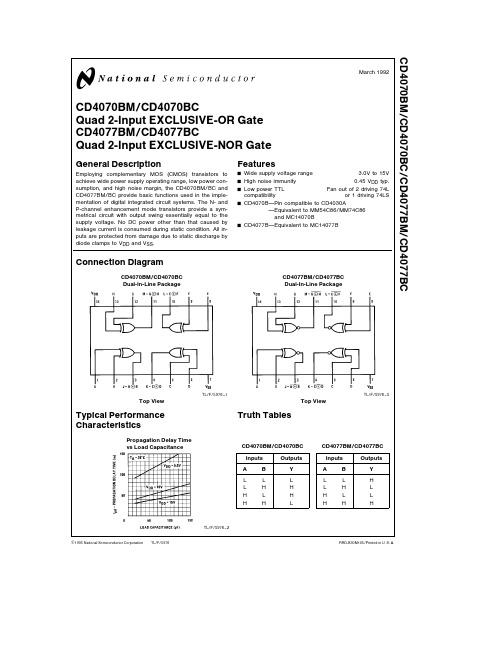
March 1992
CD4070BM CD4070BC Quad 2-Input EXCLUSIVE-OR Gate CD4077BM CD4077BC Quad 2-Input EXCLUSIVE-NOR Gate
General Description
VDD e 5V VO e 0 4V VDD e 10V VO e 0 5V VDD e 15V VO e 1 5V VDD e 5V VO e 4 6V VDD e 10V VO e 9 5V VDD e 15V VO e 13 5V VDD e 15V VIN e 0V VDD e 15V VIN e 15V 35 70 11 0 0 52 13 36
b 40 C to a 85 C b 55 C to a 125 C
700 mW 500 mW 260 C CD4077BM (Note 2)
b 55 C a 25 C a 125 C
DC Electrical Characteristics CD4070BM
Symbol IDD Parameter Quiescent DeviDD e 5V VIN e VDD or VSS VDD e 10V VIN e VDD or VSS VDD e 15V VIN e VDD or VSS
Propagation Delay Time vs Load Capacitance
Truth Tables
CD4070BM CD4070BC Inputs A L L H H B L H L H Outputs Y L H H L
CD4077BM CD4077BC Inputs A L L H H B L H L H Outputs Y H L L H
Si4708 09 编程指南说明书

AN349Si4708/09 P ROGRAMMING G UIDE1. Introduction1.1. ScopeThis document applies to Si4708/09 and example code version 0.1 and greater. Refer to for example code.1.2. PurposeThis document is intended to be used with Skyworks “AN230: Si4700/01/02/03 Programming Guide." The purpose of this programming guide is to describe features that are unique to the Si4708/09:⏹Device initialization sequence and busmode selection⏹Powerup and powerdown sequences⏹Hardware control registersFor topics that are not covered in this document, refer to AN230.This document references the Si4708/09 data sheet and AN230.1.3. TerminologySENB or SEN—serial enable pin, active low, used only for 3-wire operation.SDIO—serial data in/data out pin.SCLK—serial clock pin.RSTB or RST—reset pin, active low.Device—refers to the Si4708/09.1.4. Differences between Si4708/09 and Si4700/01/02/03The Si4708/09 uses a 2.5x2.5mm 16-pin QFN package. The Si4702/03 and Si4700/01 use 20-pin and 24-pin packages, respectively. For the purpose of programming, the key difference is that the Si4708/09 does not have GPIO1 and GPIO3 pins, and, as a result, the Si4708/09 does not offer an internal oscillator function and only offers bus mode selection with the SENB pin. This necessitates minor differences in the initialization sequence, busmode selection, powerup and powerdown sequences, and hardware control registers for the Si4708/09. Key differences between the Si4708/09 and the Si4700/01/02/03 are presented in bold text.AN3492SkyworksSolutions,Inc.•Phone[781]376-3000•Fax[781]376-3100•*********************•AN349 T ABLE OF C ONTENTS1. Introduction . . . . . . . . . . . . . . . . . . . . . . . . . . . . . . . . . . . . . . . . . . . . . . . . . . . . . . . . . . . . .11.1. Scope . . . . . . . . . . . . . . . . . . . . . . . . . . . . . . . . . . . . . . . . . . . . . . . . . . . . . . . . . . . . .11.2. Purpose . . . . . . . . . . . . . . . . . . . . . . . . . . . . . . . . . . . . . . . . . . . . . . . . . . . . . . . . . . . .11.3. Terminology . . . . . . . . . . . . . . . . . . . . . . . . . . . . . . . . . . . . . . . . . . . . . . . . . . . . . . . .11.4. Differences between Si4708/09 and Si4700/01/02/03 . . . . . . . . . . . . . . . . . . . . . . . .12. Hardware Description . . . . . . . . . . . . . . . . . . . . . . . . . . . . . . . . . . . . . . . . . . . . . . . . . . . . .42.1. Power, Initialization Sequence, and Busmode Selection . . . . . . . . . . . . . . . . . . . . . .42.2. 2-Wire Control Interface . . . . . . . . . . . . . . . . . . . . . . . . . . . . . . . . . . . . . . . . . . . . . . .63. Software Configuration . . . . . . . . . . . . . . . . . . . . . . . . . . . . . . . . . . . . . . . . . . . . . . . . . . . .73.1. Registers . . . . . . . . . . . . . . . . . . . . . . . . . . . . . . . . . . . . . . . . . . . . . . . . . . . . . . . . . . .73.2. Hardware Control Registers . . . . . . . . . . . . . . . . . . . . . . . . . . . . . . . . . . . . . . . . . . . .83.3. General Configuration Control Registers . . . . . . . . . . . . . . . . . . . . . . . . . . . . . . . . .113.4. Regional Configuration Control Registers . . . . . . . . . . . . . . . . . . . . . . . . . . . . . . . . .113.5. End User Adjustable Control Registers . . . . . . . . . . . . . . . . . . . . . . . . . . . . . . . . . . .113.6. Seek Control Registers . . . . . . . . . . . . . . . . . . . . . . . . . . . . . . . . . . . . . . . . . . . . . . .113.7. Tune Control Registers . . . . . . . . . . . . . . . . . . . . . . . . . . . . . . . . . . . . . . . . . . . . . . .113.8. RDS/RBDS (Si4709 Only) . . . . . . . . . . . . . . . . . . . . . . . . . . . . . . . . . . . . . . . . . . . . .114. Programming with Commands . . . . . . . . . . . . . . . . . . . . . . . . . . . . . . . . . . . . . . . . . . . . .125. Command and Properties . . . . . . . . . . . . . . . . . . . . . . . . . . . . . . . . . . . . . . . . . . . . . . . . .12 Appendix—Seek Adjustability and Settings . . . . . . . . . . . . . . . . . . . . . . . . . . . . . . . . . . . .13 SkyworksSolutions,Inc.•Phone[781]376-3000•Fax[781]376-3100•*********************•3AN3492. Hardware Description2.1. Power, Initialization Sequence, and Busmode SelectionFigure1.Initialization Sequence2.1.1. Hardware InitializationThe FM tuner device is capable of communicating using either a 3-wire or 2-wire interface. The selection of this interface is made during the reset sequence.Figure1 demonstrates the sequencing of hardware events relative to reset. Figure2 combines this information with the setting of the ENABLE and DISABLE bits to better describe the possible combinations. The following steps should be used to initialize the device properly.1.Supply VA and VD.2.Supply VIO while keeping the RST pin low. Note that power supplies may be sequenced in any order (steps 1and 2 may be reversed).3.Configure the SENB pin for bus mode selection. See Figure3, “Powerup, Powerdown, and Reset Flowchart,”on page 6.4.Set the RST pin high. The device registers may now be read and written.5.Provide RCLK. A delay may be necessary for some external oscillator circuits to ensure that theoscillator has stabilized. Please determine the necessary stabilization time for the clock source in the system.Note:The Si4708/09 does not offer an internal oscillator option.6.Set the ENABLE bit high and the DISABLE bit low to power up the device.2.1.2. Hardware PowerdownA powerdown mode is available to reduce power consumption when the part is idle. Setting both the ENABLE bit high and the DISABLE bit high starts the powerdown sequence. This disables analog and digital circuitry while maintaining register configuration and keeping the bus active. Note that the device automatically sets the ENABLE bit low after the internal powerdown sequence completes. Setting the ENABLE bit low directly will cause the device to partially powerdown and should be avoided. See Figure2. Setting the ENABLE bit high and the DISABLE bit low will bring the device out of powerdown mode and resume normal operation. Refer to Figure1 for more information. To power down the device:1.Set Register 4 [5:4], [3:2], and [1:0] to 0b10. This step is required for the Si4708/09 to ensure VIOpowerdown mode current meets data sheet specifications.2.Set the ENABLE bit high and the DISABLE bit high to place the device in powerdown mode. Note that allregister states are maintained so long as VIO is supplied and the RST pin is high.4SkyworksSolutions,Inc.•Phone[781]376-3000•Fax[781]376-3100•*********************•AN3493.Remove VA and VD supplies as needed.To power up the device (after power down):Note:VIO is still supplied in this scenario. If VIO is not supplied, refer to 2.1.1. "Hardware Initialization”1.Supply VA and VD.2.Set the ENABLE bit high and the DISABLE bit low to powerup the device.Setting the RST pin low will disable analog and digital circuitry, reset the registers to their default settings, and disable the bus. Setting the RST pin high will bring the device out of reset, place the device in powerdown mode, and latch which bus mode will be used to communicate with the device. The bus mode selection is determined by the SENB pin. To select 2-wire operation, the SENB pin must be sampled high by the device on the rising edge of RST. To select 3-wire operation, the SENB pin must be sampled low by the device on the rising edge of RST (See Figure3). Please refer to the data sheet for more information regarding bus selection and timing requirements of the RST signal.More details on the register access during powerup and powerdown can be found in Section "3.2.1.ENABLE (02h.0)/DISABLE (02h.6)—Powerup Control" on page 8.Note:See data sheet for further details.Figure2.Powerup, Powerdown, and Reset State DiagramSkyworksSolutions,Inc.•Phone[781]376-3000•Fax[781]376-3100•*********************•5AN349Note:See data sheet for further details.Figure3.Powerup, Powerdown, and Reset Flowchart2.1.3. Wire Control InterfaceFor information on the 3-wire control interface, refer to Section 2.2 of “AN230: Si4700/01/02/03 Programming Guide."2.2. 2-Wire Control InterfaceFor information on the 2-wire control interface, refer to Section 2.2 of “AN230: Si4700/01/02/03 Programming Guide."6SkyworksSolutions,Inc.•Phone[781]376-3000•Fax[781]376-3100•*********************•AN349SkyworksSolutions,Inc.•Phone[781]376-3000•Fax[781]376-3100•*********************• 73. Software Configuration3.1. RegistersThe control and status of the device is obtained through bitfields within 16 registers of 16 bits each. The functionality of the bits can be separated into two main categories: control and status. The control bits can be further subdivided into categories of when or how they are used (see Table 1). While the status bits can be classified as static, static after power up, or dynamic after power up (see Table 2). Note that the Si4708/09 does not offer GPIO1 or GPIO3.Table 1. Register UseBit(s)Hardware ControlGeneral ConfigRegional ConfigEnd User AdjustableSeekTuneDISABLE X ENABLE X AHIZEN X GPO X RDSIEN X STCIEN XBLNDADJ X DSMUTE X SMUTER X SMUTEA X VOLEXT X SEEKTH X SKSNR X SKCNT X RDSPRF X RDSM XRDS X DE X BAND X SPACE XDMUTE X MONO X VOLUME XSEEKUP X SKMODE X SEEK XTUNE X CHANXAN349Table 2. Status Bit ClassificationBit(s)Static Static After Power Up Dynamic After Power UpPN XMFGID XREV XDEV XFIRMWARE XST XRSSI X READCHAN X STC XSF/BL XAFCRL XRDSR XRDSS XBLERA XBLERB XBLERC XBLERD XRDSA XRDSB XRDSC XRDSD X3.2. Hardware Control RegistersThe following set of registers alter the hardware in some way. These registers are typically the first group to be programmed.3.2.1. ENABLE (02h.0)/DISABLE (02h.6)—Powerup ControlThe ENABLE/DISABLE bits are analogous to the on/off buttons of the device. ENABLE=1 turns the device on while DISABLE=1 turns the device off (powerdown mode). When writing the register to place the device into powerdown mode, ENABLE should remain set to 1 while setting DISABLE to 1. The device clears the ENABLE and DISABLE bits, indicating the powerdown mode has been entered.Table3 shows the sequence of commands required to powerup the device. Note that address 07h may be written during powerup configuration.8SkyworksSolutions,Inc.•Phone[781]376-3000•Fax[781]376-3100•*********************•AN349SkyworksSolutions,Inc.•Phone[781]376-3000•Fax[781]376-3100•*********************• 9Figure 4.Powerup TimingTable 4 shows the sequence of commands required to powerdown the device. The tuner can optionally be programmed to place the audio output pins into a high impedance state. If this is desired, set the AHIZEN bit in register 07h prior to setting the disable bit. See AN230, Section "3.2.3.AHIZEN (07h.14)—Audio High-Z Enable" on page 10 for more information. Set Register 4 [5:4] and [1:0] to 10b prior to setting the disable bit.Table 3. Powerup Configuration SequenceWrite address 02h (required).⏹Set the DMUTE bit to disable mute. Optionally mute can be disabled later when audio is needed.⏹Set the ENABLE bit high to set the powerup state.⏹Set the DISABLE bit low to set the powerup state.Example: Write data 4001h.Wait for device powerup (required).⏹Refer to the Powerup Time specification in Table7 "FM Characteristics" of the data sheet.Read addresses 00h–01h (optional).⏹The bits PN[3:0]=1 indicate the part family: Si4708/09.⏹The bits MFGID[11:0]=242h indicate Skyworks as the manufacturer.⏹The bits REV[5:0]=1 indicates silicon revision B.⏹The bits DEV indicate the identity of the device: DEV =0010 after powerup=Si4708.DEV =1010 after powerup =Si4709.⏹The FIRMWARE bits indicate the firmware revision after powerup.Read addresses 02h-0Fh (optional)⏹Storing the values of each of the 16 registers locally is recommended to simplify manipulation of register bits and to reduce the number of reads/writes to the I/O bus. These are referred to as the shadow registers and can be stored in a 16 word array, shadow_reg[].Example: To write bit 15 of register 07h after power up, write 07h as shadow_reg[0x07] ^ 0x8000Write remaining hardware configuration registers (required).Write the general configuration registers (required).Write the regional configuration registers (required).These registers can be programmed in any order.ENABLE = 1DISABLE = 0DEV = ?AN34910SkyworksSolutions,Inc.•Phone[781]376-3000•Fax[781]376-3100•*********************•Figure 5.Powerdown Timing3.2.2. XOSCEN-Crystal Oscillator Enable (Not available on Si4708/09)The internal oscillator is not available on the Si4708/09. The Si4708/09-B requires a 32.768kHz reference clock to the RCLK pin. Refer to the Si4708/09 datasheet for more information.3.2.3. AHIZEN (07h.14)—Audio High-Z EnableFor information on audio high-Z enable, refer to Section 3.2.3 of “AN230: Si4700/01/02/03 Programming Guide."3.2.4. GPIO1-General Purpose I/O 1 (Not available on Si4708/09)General purpose I/O 1 is not available on the Si4708/09.3.2.5. GPO (04h.3:2)/RDSIEN (04h.15)/STCIEN (04h.14)—General Purpose I/O, InterruptsGPO can be programmed to four different states as shown in Table 5. When programmed as an interrupt, the device will generate interrupts based on the settings of RDSIEN and STCIEN. If RDSIEN is set a 5ms interrupt pulse will be generated when RDS data is available. If STCIEN is set a 5ms interrupt pulse will be generated upon completion of a SEEK or TUNE command. If both interrupts are enabled, the first interrupt after a SEEK or TUNE will be the STC interrupt. Subsequent interrupts will be RDS interrupts. This pin can also be used as a general purpose output or left unused. RDS is only available on the Si4709.Table 4. Powerdown SequenceWrite address 07h (optional for LOUT and ROUT Hi-Z).⏹Set AHIZEN. All other bits in this register should be maintained at the value last read (i.e., 0x3C04 or 0xBC04). Example: Write data 7C04h.Write address 04h (This step is required for the Si4708/09 to reduce powerdown mode current).⏹Set Register 4 [5:4] and [1:0] to 10b. All other bits in this register should be maintained at the value last read.Example: Write data 002Ah.Write address 02h (required).⏹Clear the DMUTE bit to enable mute.⏹Set the ENABLE bit high and DISABLE bit high to set the powerdown state.⏹After the DISABLE bit is set high, the device performs an internal powerdown sequence and then sets the ENABLE and DISABLE bits low. Setting the ENABLE bit directly to 0 will cause the device to partiallypowerdown. Example:Write data 0041h.1.5 ms maxENABLE = 1DISABLE = 1ENABLE = 0DISABLE = 0AN349Table 5. GPO States00High impedance (default)01STC/RDS interrupt10Low output (GND level)11High output (VIO level)3.2.6. GPIO3-General Purpose I/O 3 (Not available on Si4708/09)General purpose I/O 3 is not available on the Si4708/09.3.3. General Configuration Control RegistersFor information on general configuration control registers, refer to Section 3.3 of “AN230: Si4700/01/02/03 Programming Guide."3.4. Regional Configuration Control RegistersFor information on regional configuration control registers, refer to Section 3.4 of “AN230: Si4700/01/02/03 Programming Guide."3.5. End User Adjustable Control RegistersFor information on end user adjustable control registers, refer to Section 3.5 of “AN230: Si4700/01/02/03 Programming Guide."3.6. Seek Control RegistersFor information on seek control registers, refer to Section 3.6 of “AN230: Si4700/01/02/03 Programming Guide."3.7. Tune Control RegistersFor information on tune control registers, refer to Section 3.7 of “AN230: Si4700/01/02/03 Programming Guide." 3.8. RDS/RBDS (Si4709 Only)For information on RDS/RBDS, refer to Section 3.8 of “AN230: Si4700/01/02/03 Programming Guide." Note this section applies to the Si4709 in addition to the Si4701/03.SkyworksSolutions,Inc.•Phone[781]376-3000•Fax[781]376-3100•*********************•11AN3494. Programming with CommandsFor information on programming with commands, refer to Section 4 of AN230 "Si4700/01/02/03 Programming Guide." Note this section applies to the Si4708/09 in addition to the Si4702/03 Rev C.5. Command and PropertiesFor information on command and properties, refer to Section 5 of AN230 "Si4700/01/02/03 Programming Guide." Note this section applies to the Si4708/09 in addition to the Si4702/03 Rev C.12SkyworksSolutions,Inc.•Phone[781]376-3000•Fax[781]376-3100•*********************•AN349 A PPENDIX—S EEK A DJUSTABILITY AND S ETTINGSFor information on seek adjustability and settings, refer to the Appendix in “AN230: Si4700/01/02/03 Programming Guide."SkyworksSolutions,Inc.•Phone[781]376-3000•Fax[781]376-3100•*********************•13Copyright © 2021 Skyworks Solutions, Inc. All Rights Reserved.Information in this document is provided in connection with Skyworks Solutions, Inc. (“Skyworks”) products or services. These materials, including the information contained herein, are provided by Skyworks as a service to its customers and may be used for informational purposes only by the customer. Skyworks assumes no responsibility for errors or omissions in these materials or the information contained herein. Skyworks may change its documentation, products, services, specifications or product descriptions at any time, without notice. Skyworks makes no commitment to update the materials or information and shall have no responsibility whatsoever for conflicts, incompatibilities, or other difficulties arising from any future changes.No license, whether express, implied, by estoppel or otherwise, is granted to any intellectual property rights by this document. Skyworks assumes no liability for any materials, products or information provided hereunder, including the sale, distribution, reproduction or use of Skyworks products, information or materials, except as may be provided in Skyworks’ Terms and Conditions of Sale.THE MATERIALS, PRODUCTS AND INFORMATION ARE PROVIDED “AS IS” WITHOUT WARRANTY OF ANY KIND, WHETHER EXPRESS, IMPLIED, STATUTORY, OR OTHERWISE, INCLUDING FITNESS FOR A PARTICULAR PURPOSE OR USE, MERCHANTABILITY, PERFORMANCE, QUALITY OR NON-INFRINGEMENT OF ANY INTELLECTUAL PROPERTY RIGHT; ALL SUCH WARRANTIES ARE HEREBY EXPRESSLY DISCLAIMED. SKYWORKS DOES NOT WARRANT THE ACCURACY OR COMPLETENESS OF THE INFORMATION, TEXT, GRAPHICS OR OTHER ITEMS CONTAINED WITHIN THESE MATERIALS. SKYWORKS SHALL NOT BE LIABLE FOR ANY DAMAGES, INCLUDING BUT NOT LIMITED TO ANY SPECIAL, INDIRECT, INCIDENTAL, STATUTORY, OR CONSEQUENTIAL DAMAGES, INCLUDING WITHOUT LIMITATION, LOST REVENUES OR LOST PROFITS THAT MAY RESULT FROM THE USE OF THE MATERIALS OR INFORMATION, WHETHER OR NOT THE RECIPIENT OF MATERIALS HAS BEEN ADVISED OF THE POSSIBILITY OF SUCH DAMAGE.Skyworks products are not intended for use in medical, lifesaving or life-sustaining applications, or other equipment in which the failure of the Skyworks products could lead to personal injury, death, physical or environmental damage. Skyworks customers using or selling Skyworks products for use in such applications do so at their own risk and agree to fully indemnify Skyworks for any damages resulting from such improper use or sale.Customers are responsible for their products and applications using Skyworks products, which may deviate from published specifications as a result of design defects, errors, or operation of products outside of published parameters or design specifications. Customers should include design and operating safeguards to minimize these and other risks. Skyworks assumes no liability for applications assistance, customer product design, or damage to any equipment resulting from the use of Skyworks products outside of Skyworks’ published specifications or parameters.Skyworks, the Skyworks symbol, Sky5®, SkyOne ®, SkyBlue™, Skyworks Green™, Clockbuilder ®, DSPLL ®, ISOmodem ®, ProSLIC ®, and SiPHY ® are trademarks or registered trademarks of Skyworks Solutions, Inc. or its subsidiaries in the United States and other countries. Third-party brands and names are for identification purposes only and are the property of their respective owners. Additional information, including relevant terms and conditions, posted at , are incorporated by reference.Portfolio Quality /quality Support & Resources /supportSkyworksSolutions,Inc.|Nasdaq:SWKS|*********************|USA: 781-376-3000 | Asia: 886-2-2735 0399 | Europe: 33 (0)1 43548540 |。
MAXIM DS4077 数据手册

General DescriptionThe DS4077 is an integrated voltage-controlled crystal oscillator (VCXO) module designed to provide reference clock generation in base stations, telecom/datacom, and wireless applications. The DS4077 is developed using a fundamental quartz crystal plus a unique integrated cir-cuit design. The internal fundamental quartz crystal determines the frequency of operation. Custom frequen-cies are available. Contact the factory for availability.The DS4077 is designed for use with applications requir-ing low phase noise and jitter. Jitter performance of bet-ter than 1ps RMS is achieved over the 12kHz to 80MHz range. Phase noise performance of better than -130dBc/Hz at 1kHz is achieved with this design.Features♦77.76MHz (f NOM ) Frequency ♦3.135V to 3.465V Operation ♦Low Jitter: < 1ps RMS♦±69ppm Absolute Pull Range (APR)♦Output Options:LVCMOS Output BufferLVDS Complementary Output Buffer ♦Minimum ±110ppm Tuning Range (+25°C)♦14mm x 9mm x 3.06mm Plastic LGA PackageDS407777.76MHz VCXO______________________________________________Maxim Integrated Products 1Pin ConfigurationRev 1; 12/05For pricing, delivery, and ordering information,please contact Maxim/Dallas Direct!at 1-888-629-4642, or visit Maxim’s website at .Ordering Information*The top mark includes an “N” for industrial temperature grade devices.Block Diagram查询DS33R11DK供应商D S 407777.76MHz VCXO 2_____________________________________________________________________ABSOLUTE MAXIMUM RATINGSELECTRICAL CHARACTERISTICSStresses beyond those listed under “Absolute Maximum Ratings” may cause permanent damage to the device. These are stress ratings only, and functional operation of the device at these or any other conditions beyond those indicated in the operational sections of the specifications is not implied. Exposure to absolute maximum rating conditions for extended periods may affect device reliability.VC, V DD , LVCMOS, LVDSO+, LVDSO- Output........-0.3V, +3.6V Operating Temperature Range(noncondensing)..............................................-40°C to +85°C Junction Temperature......................................................+150°C Thermal ResistanceJunction to Ambient.................................................91.06°C/W Junction to Case......................................................44.51°C/WStorage Temperature Range.............................-55°C to +125°C Soldering Temperature(reflow, 2 passes max)....See IPC/JEDEC STD-020 SpecificationDS407777.76MHz VCXO_____________________________________________________________________3ELECTRICAL CHARACTERISTICS (continued)Note 2:10pF, LVCMOS.Note 3:Guaranteed by design and not production tested.Note 4:100Ωdifferential load.Pin DescriptionD S 407777.76MHz VCXO Maxim cannot assume r esponsibility for use of any cir cuitr y other than cir cuitr y entir ely embodied in a Maxim pr oduct. No cir cuit patent licenses ar e implied. Maxim reserves the right to change the circuitry and specifications without notice at any time.4_____________________Maxim Integrated Products, 120 San Gabriel Drive, Sunnyvale, CA 94086 408-737-7600©2005 Maxim Integrated ProductsPrinted USAis a registered trademark of Maxim Integrated Products, Inc.is a registered trademark of Dallas Semiconductor Corporation.Package Information(For the latest package information, go to /DallasPackInfo and click on package drawing 56-G6034-001.)Typical Operating Characteristics(V CC = +3.3V, T A = +25°C, unless otherwise noted.)FREQUENCY vs. TEMPERATURETEMPERATURE (°C)f O U T D E V I A T I O N (p p m )604020-20-8-6-4-20246810-10-4080LVCMOS OUTPUT FREQUENCY vs. LOAD CAPACITANCE vs. VCVC (V)f O U T D E V I A T I O N (p p m )2.81.82.31.30.8-50-75-1001251007550250-25150-1250.3OUTPUT FREQUENCY vs. SUPPLY VOLTAGE vs. VCV DD (V)f O U T D E V I A T I O N F R O M V D D = 3.3V (p p m )3.410 3.4653.3553.1903.245 3.300-10-15151050-520-203.135。
STM32f407系统定时器时钟配置、计算

STM32f407系统定时器时钟配置、计算STM32f407系统定时器时钟配置、计算1. 外部晶振的选择##确定自己单片机的外部晶振系统默认配置为25M,即打开官方库文件参数HSE Frequency(Hz) 一般为25000000HSE Frequency(Hz) | 25000000----------#if !defined (HSE_VALUE)#define HSE_VALUE ((uint32_t)25000000) /*!<Value of the External oscillator in Hz */#endif /* HSE_VALUE */... ... ...我自己的单片机外部晶振为8M,将参数改为80000002. 系统时钟确定2.1 改完之后参照stm32f4时钟树2.2 首先明确自己的系统总时钟找到自己程序PLL Parameters部分(工程system_stm32f4xx.c) /************************* PLL Parameters***************************//* PLL_VCO = (HSE_VALUE or HSI_VALUE / PLL_M) * PLL_N */ //锁相环压腔振荡器时钟//PLL_VCO =(HSE_VALUE/PLL_M)* PLL_N=8/ 8* 336 = 336MHz#define PLL_M 8#define PLL_N 336/* SYSCLK = PLL_VCO / PLL_P */// 系统时钟SYSCLK = PLL_VCO / PLL_P=336 / 2 = 168MHz #define PLL_P 2/* USB OTG FS, SDIO and RNG Clock = PLL_VCO / PLLQ */ //USB,SD卡时钟= PLL_VCO / PLLQ=336 / 7 = 48MHz#define PLL_Q 7/************************************************************** *****/3. 计算出自己系统时钟为168M##3.1 对应时钟线这里需要计算各个定时器分配所得的计数时钟频率3.2 找到APB1,APB2配置部分3.3 程序位置/* Select regulator voltage output Scale 1 mode, System frequency up to 168 MHz */RCC->APB1ENR |= RCC_APB1ENR_PWREN;PWR->CR |= PWR_CR_VOS;/* HCLK = SYSCLK / 1*/RCC->CFGR |= RCC_CFGR_HPRE_DIV1;/* PCLK2 = HCLK / 2*/RCC->CFGR |= RCC_CFGR_PPRE2_DIV2;/* PCLK1 = HCLK / 4*/RCC->CFGR |= RCC_CFGR_PPRE1_DIV4;/* Configure the main PLL */RCC->PLLCFGR = PLL_M | (PLL_N << 6) | (((PLL_P >> 1) -1) << 16) |(RCC_PLLCFGR_PLLSRC_HSE) | (PLL_Q << 24);3.4 位置计算15:13位为 010 ----->AHB2 不分频12:10位为 101 ----->AHB1 4分频e. 原则“非1即2”明确APB1得到时钟84M,APB2计数时钟频率168M 4. 系统默认情况:4.1 定时周期、频率的计算/****************************************************默认配置:外部时钟启动失败,系统会自动使用内部时钟*HCLK = SYSCLK / 1 = 168MHz ,AHB×总线时钟*PCLK2 = HCLK / 2 = 84MHz*PCLK1 = HCLK / 4 = 42MHz* arr:自动重装载值* psc:时钟预分频树* 定时器溢出时间计算方法:T out=((arr+1)*(psc+1))/Ft us.* Ft=定时器工作频率,单位:Mhz*****************************************************/ 4.2 实例验证演示。
AT32F403A 407时钟配置入门指南说明书

AN0082入门指南AT32F403A/407时钟配置前言本应用入门指南主要介绍两部分内容:1、基于雅特力提供的V2.x.x的板级支持包来进行时钟源码的配置及修改2、如何使用配套的时钟配置工具来进行时钟路径及参数的设定,生成相应的时钟流程代码并使用。
支持型号列表:AT32F403Axx支持型号AT32F407xx目录1简介 (6)2时钟树 (7)3代码配置解析 (9)3.1函数接口 (9)3.2时钟配置流程 (10)3.2.1复位(CRM Reset) (10)3.2.2时钟源配置(Clock Source Configuration) (10)3.2.3PLL配置(PLL Configuration) (11)3.2.4总线分频(Set Bus Frequency Division) (11)3.2.5切换系统时钟(Switch System Clock) (11)3.2.6更新核心频率(Update Core Frequency) (12)3.3时钟配置示例 (13)4时钟工具 (14)4.1环境要求 (14)4.2安装 (14)4.3功能介绍 (14)4.4菜单栏 (15)4.5新建配置项目 (15)4.6配置界面的使用 (16)4.7生成代码 (18)5注意事项 (19)5.1外部时钟源(HEXT)修改 (19)5.2工具使用 (19)6案例系统时钟切换 (20)6.1功能简介 (20)6.2资源准备 (20)6.3软件设计 (20)6.4实验效果 (22)7案例时钟失效检测 (23)7.1功能简介 (23)7.2资源准备 (23)7.3软件设计 (23)7.4实验效果 (24)8文档版本历史 (25)表1. 文档版本历史 (25)图1. 时钟框图 (7)图2. 时钟配置流程图 (10)图3. 启动界面 (14)图4. 配置界面 (15)图5. 菜单栏 (15)图6. MCU选择界面 (16)图7. 配置界面框架 (16)图8. 时钟配置框 (17)1 简介时钟是芯片正确高效运行的基础,正确的时钟配置是芯片能正确运行的必要条件,其重要性不言而喻。
系统控制专业知识讲座培训课件

寄存器 11: 深度睡眠时钟配置(DSLPCLKCFG),偏移量 0x144这个寄存器为深度睡 眠模式旳硬件控制提供了配置信息。
寄存器 20: 深度睡眠模式时钟选通控制寄存器0 (DCGC0), 偏移量 0x120该寄存 器用来控制时钟选通逻辑。每个位控制一种给定接口、功能、或单元旳时钟使能。假 如置位,则相应旳单元接受时钟并运营。不然,相应旳单元不使用时钟并禁止(节 能)。假如功能单元不使用时钟,那么在对该单元进行读或写操作时都将返回总线故 障。除非尤其阐明,不然这些位旳复位状态都为0(不使用时钟),即全部功能单元都 禁止。应用所需旳端口需经过软件来使能。注:这些寄存器除了具有对接口、功能、 或单元进行控制旳位以外,还可能具有其他位,这么可确保与其他系列以及将来旳部 件实现合理旳代码兼容。 RCGC0 是运营操作旳时钟配置寄存器,SCGC0 是睡眠操作 旳时钟配置寄存器,DCGC0 是深度睡眠操作旳时钟配置寄存器。当运营模式时钟配置 (RCC)寄存器中旳ACG位置位时表达系统使用睡眠模式。
寄存器 21: 运营模式时钟选通控制寄存器1 (RCGC1), 偏移量 0x104该寄存器控制时钟选通逻辑。每个位控制一种给定接口、功能、 或单元旳时钟使能。假如置位,则相应旳单元接受时钟并运营。不然, 相应旳单元不使用时钟并禁止(节能)。假如功能单元不使用时钟, 那么在对该单元进行读或写操作时都将返回总线故障。除非尤其阐明, 不然这些位旳复位状态都为0(不使用时钟),即全部功能单元都禁 止。应用所需旳端口需经过软件来使能。注:这些寄存器除了具有对 接口、功能、或单元进行控制旳位以外,还可能具有其他位,这么可 确保与其他系列以及将来旳部件实现合理旳代码兼容。 RCGC1是运营 操作旳时钟配置寄存器,SCGC1是睡眠操作旳时钟配置寄存器, DCGC1是深度睡眠操作旳时钟配置寄存器。当运营模式时钟配置(RCC) 寄存器旳ACG位置位时,表达系统使用睡眠模式。
407元器件 作用

407元器件作用407元器件的作用随着科技的不断发展,电子设备已经成为我们日常生活中不可或缺的一部分。
而在电子设备中,各种各样的器件起着至关重要的作用。
本文将重点介绍407元器件的作用。
407元器件是一种多功能集成电路,具有多种功能和特性。
它在电子设备中起着连接、控制、放大、滤波等多种作用。
下面将详细介绍407元器件的几个主要作用。
407元器件可以实现电路的连接功能。
在电子设备中,各个电路之间需要进行连接,以实现信息的传输和处理。
407元器件作为一种连接器件,可以将各个电路连接在一起,形成一个完整的电子系统。
它可以通过引脚和线路连接其他元器件,实现电路的通信和协调工作。
407元器件可以实现信号的放大和处理功能。
在电子设备中,信号的强弱和稳定性对于电路的工作效果至关重要。
407元器件内部的放大电路可以对输入信号进行放大,增加信号的幅度,提高信号的质量和稳定性。
另外,407元器件还可以对信号进行滤波和调节,使信号更加清晰和稳定,以满足电子设备的需求。
407元器件还可以实现电路的控制功能。
在电子设备中,往往需要对各个电路进行控制和调节,以实现不同的功能和操作。
407元器件内部的控制电路可以根据输入信号的变化,对其他元器件进行控制和操作。
它可以根据设定的参数和条件,对电子设备进行精确的控制,实现各种不同的功能。
407元器件还具有存储和计算功能。
在一些特定的电子设备中,需要对数据进行存储和计算,以实现复杂的操作和处理。
407元器件内部的存储器和计算器可以对数据进行存储和计算,提高电子设备的运行效率和处理能力。
它可以存储大量的数据,并进行高速的计算,满足电子设备对于数据处理的需求。
总结起来,407元器件在电子设备中起着连接、控制、放大、滤波、存储和计算等多种作用。
它是电子设备中不可或缺的一部分,是电子系统正常运行的关键。
通过407元器件的应用,电子设备可以实现各种不同的功能和操作,提高工作效率和性能。
不论是通信设备、计算机、家电还是汽车电子等领域,407元器件都扮演着重要的角色。
40m无源晶振匹配电路

40m无源晶振匹配电路
内容:
40米波段的无源晶振匹配电路主要用于40米波段的无线通信系统。
其结构通常由晶振、电容和电感组成。
1. 晶振选择
40米波段晶振的共振频率一般在35-50范围。
为了获得稳定的频率,需要选择温度稳定性好的晶振。
常用的有切晶振、切晶振等。
2. 匹配电路
晶振的共振回路可以用并联谐振电路实现。
在晶振两端并联适当大小的电容,可以得到所需的共振频率。
然后在晶振一端接入电感,形成串联谐振回路,提供晶振所需的负载电容。
通过调节电容和电感的大小,可以达到晶振的最佳工作条件,使其输出稳定的信号。
匹配电路还需要考虑晶振的工作温度范围,保证在温度变化时频率稳定。
3. 封装与布线
40的信号较为敏感,布线需要考虑寄生参数的影响。
信号线应该短而直,尽量避免在上打弯。
晶振、电容、电感应靠近布置,减小寄生参数。
同时,合理的布局和接地可以有效抑制噪声干扰。
4. 微调
由于工艺的影响,实际匹配电路的参数可能与设计值有一定偏差。
可以通过微调电容或电感的值,使频率调整到精确的值,满足系统需求。
久川变频器基本参数
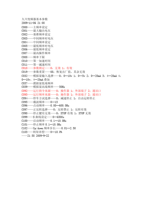
久川变频器基本参数
2009-11-06 21:08
C000——主频率设定
C001——最大输出电压
C002——基准频率设定
C003——中间频率时电压
C004——中间频率设定
C005——最低频率时电压
C006——最低频率设定
C007——最高操作频率
C008——频率下限
C010——第一加速时间
C011——第一减速时间
C018——参数锁定——0:无效 1:有效
C019——参数重置——08:恢复出厂值,其余无效
C032——模拟量输入选择——0:0--10v 1:0--5v 2:0--20mA 3:4--20mA 4:0--10v,4--20mA叠加
C037——摸拟量低端频率
C039——模拟量高端频率——50Hz
C092——运行指令来源——0:操作器 1:外部端子 2;通讯口
C093——运行频率来源——0:操作器 1:外部端子 2;通讯口
C094——停车方试选择——0:减速停止 1:自由运转停止
C095——载波频率——0--15
C096——点动频率——0.00--600.0Hz
C097——正反转选择——0:反转禁止 1:反转有效
C098——停止键有无效——0:STOP有效 1:STOP无效
C099——S曲线设定——0--6500s
C100——启动频率——0.1--10.0Hz
C101——停止频率0.1--10.0Hz
C102——Up/down频率步长——0.01--2.50
C103——转矩补偿——0--10.0%
——21:58 2009-9-22。
AS-407肺功能分析仪简介

AS-407肺功能分析仪简介产品介绍1.采用铂-铑合金材料的热丝式流速传感器:流量测量范围:0-14L/S;体积测量范围:0-10L流量精确度:读数值的±3\%或±0.01L/S;2.测试项目多:FVC(用力肺活量);36个参数(含2条曲线)多次测试,选优打印VC(肺活量);9个参数(含1条曲线)多次测试,选优打印BD(药物扩张试验);测试结果详尽和图表丰富(含有COPD诊断图和字形诊断图和星形图)3.特设有四种报告格式供选择:•所有数据和曲线格式的报告•详细格式的数据和曲线报告•正常格式的数据和曲线报告•大号字符显示的最短的数据和曲线报告※4.特设有四套预计值公式:•EUROPE•BEIJING•LAM-CHINA•BALDWIN5.采用最新科技技术,材料全新设计制造:•采用先进5.7英寸彩色液晶触摸屏技术,显示清晰,操作简单;一改过去的按钮等旧式操作技术;•采用日本呼吸学会对肺功能仪的精度管理指导和美国(ATS)质量控制;•肺年龄参数引入到肺功能测试中,使得测试和科研更完善;•吸烟指数引入到肺功能分析报告中;•预计的流速容量环显示;测试过程有警示音和柱形图提示,并显示呼吸气时间;使得操作更简单;•采用高速,安静,清晰的内置热敏打印机;•紧凑型存储可保存多达10份完整测试报告;•采用GOLD(2003年版)对COPD的病期分类;病情分析更细化;•配有采用一次性抗菌过滤性口件防止交叉感染技术,使得测试更安全;主机1台传感器1个纸口件(100个)1盒打印纸1个鼻夹1个滤室1个滤网1个电源线1根说明书1本AS-407肺功能分析仪特点>>采用铂 - 铑合金材料的热丝式流速传感器,流量测量范围: 0-14L/SAS-407肺功能分析仪应用>>AS-407肺功能分析仪,广泛应用于医院、疾病防控中心等卫生医疗保健机构,AS-407肺功能分析仪的厂家很多,应用广泛,各种产品之间的差别也比较大。
- 1、下载文档前请自行甄别文档内容的完整性,平台不提供额外的编辑、内容补充、找答案等附加服务。
- 2、"仅部分预览"的文档,不可在线预览部分如存在完整性等问题,可反馈申请退款(可完整预览的文档不适用该条件!)。
- 3、如文档侵犯您的权益,请联系客服反馈,我们会尽快为您处理(人工客服工作时间:9:00-18:30)。
HOWTO REMOVE A VOLUNTEER(MCS 407)Be sure each participant has the chapter on “How to Remove a Volunteer” from the latest Commissioner Fieldbook.Present the following material with the help of a prepared flip chart or overhead slides. Allow plenty of time for discussion after each section.I. OVERVIEWAs a commissioner, you should be prepared to help guide volunteers with how to remove a volunteerNote: This session does not address removing a person for cause or grounds for legal action such as theft, misrepresentation, or committing an immoral act.(That information exists elsewhere.)This session will focus on the ineffective volunteer, the person who just isn’t working out.First, here are some types of poor performance:1. Bad chemistry.This r efers to the person who just can’t get along with othersand may even greatly offend some, driving good people out of Scouting.2. Bad politics. This volunteer is a poor team player who is not in keeping withthe organization’s image.This person prevents others from being effectiveand may also drive them out of Scouting.This volunteer may hate his or herScouting responsibility and lets others know it.3. Bad job.This volunteer may be a nice person but simply doesn’t per formassigned tasks and can’t see m to meet the objectives of his or her Scoutingresponsibilities.II. WHATTO DOGuide volunteers with these ideas first. Sometimes easy solutions work.•Some people simply don’t know what to do, so train them. Sit down for afriendly and helpful coaching session.• Find something else for them to do in Scouting. Most people have things they can do well. Discover their hidden talents. Gracefully change their assignment to build on their strengths.•Some people try to do too much in Scouting.That’s oft en our fault. We haveasked them to do more than is reasonable, so reduce their workload.•Get your facts straight; don’t act on hearsay.•Sit down in a relaxed setting to talk about what’s going on. Often the person is the first to know things aren’t working out but might be reluctant to ask for help.Ill. IF ALL ELSE FAILSThere will be times when a volunteer has gone beyond the point where the coaching, training, or change of assignment will help. Quick action might need to be taken for the good o f Scouting. Don’t let a bad problem fester. Now what?First, you don’t really “fire” a volunteer, you replace one. “Hire” and “fire” are words for the workplace, not volunteer organizations. Replacing a volunteer sounds more positive.IV. W HO HASTHE AUTHORITY?Who has the authority to remove a volunteer? A good rule of thumb is this:The person or group with the authority to appoint a volunteer has the authority to remove and replace that volunteer. For example, a district commissioner appoints an assistant district commissioner (ADC); the district commissioner may clearly find a replacement for the ADC.In the case of unit Scouters, commissioners must remember that it is the chartered organization that has made the appointment.The commissioner role is to help the head of the chartered organization or other key unit Scouter make the change.In the case of an elected officer, the local council may decide to go through thenominating committee process.V. NOWACTWrite or make a visit. Here are some ideas you can suggest to key people in your chartered organization or district.If writing, use some variation of the following:DearOn behalf of the __________ Council (or the chartered organization), I extend our thanks for your role in ________ (unit or district).Your time, efforts, and involvement areappreciated.Your replacement has been nominated and confirmed by___________.This is effective _______ (date).Your support in this transition would be appreciated as the _________(organization/unitIcommittee/etc~) endeavors to carry out the policies andprocedures of the BSA.•If you visit (in most cases, this is best), don’t go alone. Having a second personalong might keep things under control and running smoothly. Here are a fewadditional tips:—Make an appointment. Say that you want to talk about his or her future as a______ in Scouting, and mention the volunteer who is coming with you. Refuseto say more. He or she should get the message.—Be businesslike, brief, and pleasant.TelI the person that you have made a mistake. He or she apparently isn’t able to carry out the assignment.Youhad assumed otherwise, and that was your mistake. Commend the personsother contributions in or out of Scouting, but indicate that you must nowtake action to replace the volunteer in this assignment. Be factual. Beprepared to listen. Don’t argue.—Honor the person’s dignity and avoid gossip. Don’t verbally attack the volunteer. Protect his or her self-esteem. Share the responsibility and say,“We’ve both made some mistakes!’ Don’t dump all of the blame on theother person. Don’t say something you might be sorry for later Just explain,wait, listen, repeat yourself if necessary, and leave.—Be prepared for four possible reactions.The volunteer might:1. Be smooth and controlled2. Be shocked and emotional3. Become angry4. Be relieved and ready to discuss practical solutions for the future—Before pulling the plug, make sure members of the next higher authority toyou are behind you.Then you can tell the person that the decision isnonnegotiable.Some of this may seem a bit strong.There is no joy in this task for anyone.Removing a volunteer is one of a leader’s most difficult tasks. It requiresdiscipline, good judgment, and sensitivity. Always keep two things in mind: (1)Do what’s best for youth, and (2) the BSA has a right to choose its leaders. VI. L EARN FORTHE FUTURETry to do the following:•Get a clear understanding of the assignment before recruiting.•Select the right person.•Try new people out a bit at a time.•Train and coach.•Have an understanding of what constitutes a job well done.。
