GP2A25J0000F;GP2A25NJJ00F;中文规格书,Datasheet资料
罗格朗选型手册2014
雨中的她作文雨中的她作文突然之间感到到有点凉了,抬开端停下笔,才发明,下雨了,看着哗哗的大雨我又瞅睹了这茫茫大雨中晶莹的身影……那天凌晨,气象很佳心境也不错,正筹备往上学。
没留神脚下,一块碎碗片猛飞了讫来,把我的足腕划启了一路深深的心子,登时,鲜血如注,染红了一只鞋子。
爸妈疾速地助我包扎恶,我委曲地拖着蒙伤的`脚去上学了。
实是屋破偏遇连夜雨,立刻就要抬学了老地却忽然变了脸,下伏了大雨。
望往返野是不言了,爸妈皆忙,也没时光去给我迎伞,口想饥一顿也没什么大不了的。
同窗们陆断分开了教室,方才热烈的教室一下子宁静了下来,只闻声大雨澎湃的声音。
就在这时,数教老师走到尔的眼前,亲热地答∶“我,你怎么还没回家,没带伞吗?”我不想给老师添麻烦,没告知老师实在的情形,只说还有些功课没干完。
不想,还有个同学在教室,他听到了我跟老师的对话,把事件告诉了老师。
老师又走归来对我说讲∶“ 有什么事应当向同学或老师说说,共学们,老师们都会努力辅助你的,替什么要本人一集体蒙受呢?”我无语了,老师转了一圈也走没了学室,消散在茫茫大雨中。
功了赖长时间,我还在那面寻思。
突然,一单手从我背地拍了一下我的肩膀。
我回过火来,本来是我的数学老师,她和颜悦色地说在想什么呢?想的那么进神。
交着又递给我一个饭盒说∶“叙趁暖吃吧,吃了寒的对身材不美”。
看着桌子上热腾腾的米饭,眼泪不禁盈眶而出,我慢徐地端起那碗热腾腾的米饭她在我点前卧下,疏切地说谈“有了困难要告诉老师和同学们,不管什么事,老师和同学们都会绝力赞助你。
有艰苦并不恐怖,只有你去战胜,再大的难题都能够结决”。
说完,老师默默地看我吃了一会饭说说∶“你缓缓吃饭,老师过一会来拿碗”。
我微微地,由衷地向老师说了声∶“谢谢”,别客气,渐渐吃。
看着老师离去的腹影消逝在茫茫大雨之中,我的心就像这一碗米饭热乎乎的。
接下来的多少天来时都为我送饭。
好长时间,我才被一声雷声惊醒,从那美妙的回想中回到面前。
GP2A25中文资料

-
Dissipation current (II)
ICCP *1 VCC = 5V, peak pulse value
-
Low level output voltage High level output voltage Non-detecting distance
V OL VCC =5V, IOL=16mA, at detecting time
-
V OH VCC =5V, RL=1kΩ , at non-detecting time 4.5
L LHL *2Kodak 90% reflective paper, VCC =5V
-
Detecting distance
L HLS
*2Kodak 90% reflective paper, VCC =5V *2Black paper, VCC =5V
-
L HLL
*2Kodak 90% reflective paper, VCC =5V *2Black paper, VCC =5V
9.0 7.0
Response time External disturbing light illuminance
tPHL tPLH
*3VCC= 5V
EV1
*4
EV2
(Volume : 30% less than GP2A20) 3. Long focal distance type (Optimum detecting distance : 3 to 7 mm) 4. Capable of TTL direct connection
s Outline Dimensions
3 000 1 500
*1 Test Condition for Peak Pulse Value ICCP
QS5K2TR;中文规格书,Datasheet资料
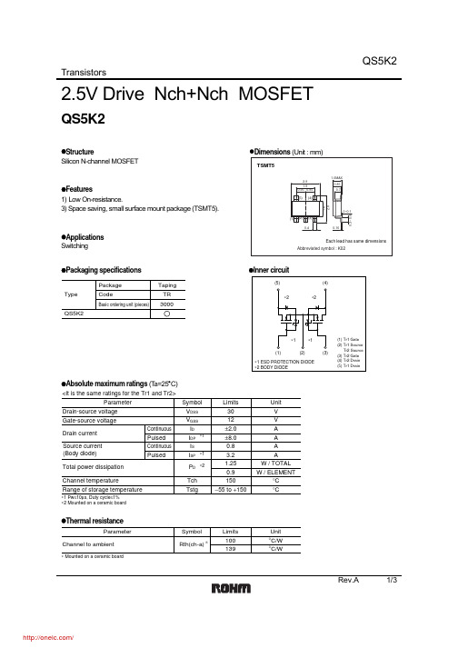
TransistorsRev.A 1/32.5V Drive Nch+Nch MOSFETQS5K2z Structure z Dimensions (Unit : mm) Silicon N-channel MOSFETz Features1) Low On-resistance.3) Space saving, small surface mount package (TSMT5).zSwitchingz Packaging specifications z Inner circuitz Absolute maximum ratings (T a=25°C)∗1∗2∗1ParameterV V DSS Symbol V V GSS A I DA I DP A I SAI SP W / TOTAL P D °C Tch °CTstgLimits Unit Drain-source voltage Gate-source voltage Drain current Total power dissipation Channel temperatureRange of storage temperatureContinuous Pulsed Continuous Pulsed∗1 Pw ≤10µs, Duty cycle ≤1%∗2 Mounted on a ceramic boardSource current (Body diode)30150−55 to +15012±2.0±8.00.83.21.25W / ELEMENT0.9<It is the same ratings for the Tr1 and Tr2>z Thermal resistanceParameter°C/W Rth(ch-a)Symbol Limits Unit Channel to ambient100°C/W139∗ Mounted on a ceramic board∗TransistorsRev.A 2/3z Electrical characteristics (T a=25°C)z Body diode characteristics (Source-drain) (T a=25°C)V SD −−1.2VI S = 3.2A, V GS =0VForward voltage∗ PulsedParameter Symbol Min.Typ.Max.UnitConditions∗<It is the same characteristics for the Tr1 and Tr2>TransistorsRev.A 3/3DRAIN-SOURCE VOLTAGE : V DS (V)101001000C A P A C I T A N C E : C (p F )Fig.1 Typical Capacitancevs. Drain-Source VoltageGATE-SOURCE VOLTAGE : V GS (V)0.0010.010.1110D R A I N C U R RE N T : I D (A )Fig.4 Typical Transfer CharacteristicsSOURCE-DRAIN VOLTAGE : V SD(V)S O U R C E C U R R E N T : I S (A )Fig.6 Source Current vs. Source-Drain VoltageGATE-SOURCE VOLTAGE : V GS (V)100200300S T A T I C D R A I N -S O U R C E O N -S T A T E R E S I S TA N C E : R D S (m Ω)Fig.5 Static Drain-SourceOn-State Resistance vs.Gate source Voltagez Electrical characteristics curvesDRAIN CURRENT : I D (A)1101001000S W I T C H I N G T I M E : t (n s )Fig.2 Switching CharacteristicsTOTAL GATE CHARGE : Qg (nC)123456G A T E -S O U R C E V O L T A G E : V G S (V )Fig.3 Dynamic Input CharacteristicsDRAIN CURRENT : I D (A)S T A T I C D R A I N -S O U R C E O N -S T A T E R E S I S T A N C E : R D S (o n ) (m Ω)Fig.7 Static Drain-Source On-State Resistance vs. Drain Current ( Ι )DRAIN CURRENT : I D (A)S T A T I C D R A I N -S O U R C E O N -S T A T E R E S I S T A N C E : R D S (o n ) (m Ω)Fig.8 Static Drain-Source On-State Resistance vs. Drain Current ( ΙΙ )DRAIN CURRENT : I D (A)S T A T I C D R A I N -S O U R C E O N -S T A T E R E S I S T A N C E : R D S (o n ) (m Ω)Fig.9 Static Drain-Source On-State Resistance vs. Drain Current ( ΙΙΙ )AppendixAbout Export Control Order in JapanProducts described herein are the objects of controlled goods in Annex 1 (Item 16) of Export T rade ControlOrder in Japan.In case of export from Japan, please confirm if it applies to "objective" criteria or an "informed" (by MITI clause)on the basis of "catch all controls for Non-Proliferation of Weapons of Mass Destruction.Appendix1-Rev1.1分销商库存信息: ROHMQS5K2TR。
RF071M2STR;中文规格书,Datasheet资料

1.2
0.85
Features 1)Small power mold type.(PMDU) 2)Ultra low VF 3)Ultra high switching speed 4)Low switching loss Construction Silicon epitaxial planer
2.6±0.1
3.5±0.2
PMDU
0.9±0.1
Structure
0.8±0.1
ROHM : PMDU JEDEC :SOD-123 Manufacture Date
Taping dimensions (Unit : mm)
4.0±0.1 2.0±0.05 φ1.55±0.05
3.5±0.05
CAPACITANCE BETWEEN TERMINALS:Ct(pF)
810
REVERSE CURRENT:IR(nA)
Ta=25℃ IF=0.7A n=30pcs
90
Ta=25℃ VR=200V n=30pcs
90 80 70 60 50 40 30 20 10 0 AVE:37.0pF
Ta=25℃ f=1MHz VR=0V n=10pcs
Limits 200 200 1 0.7 15 150 55 to 150
Unit V V A A A °C °C
Electrical characteristics(Ta=25°C) Parameter Forward voltage Reverse current Reverse recovery time
Symbol VF IR
Min. -
Typ. 0.79 0.01 12
Max. 0.85 10 25
2.5英寸硬盘商品说明书

CONTINUED > 2.5-Inch HDD pg 2CONTINUED > 2.5-Inch SSD pg 3New Seagate Model Number Key, EnterpriseST 500 NM 123 1BRANDCAPACITYSEGMENTATTRIBUTESGENERATION2 letters ST = Seagate MX = Maxtor2 to 4 digits 500 = 500GB 1000 = 1000GBCapacities >9999GB:10 = 10TB 15 = 15TB2 lettersMM = Mission-Critical, 2.5-Inch, 10K MX = Mission-Critical, 2.5-Inch, 15K NM = Nearline, 3.5-Inch NX = Nearline, 2.5-Inch FM = SSD Mainstream FX = SSD Performance3 digits, non-intelligentVaries as needed, for example:Interface RPM Cache SED1 digit, intelligent 1 = 1st Generation2 = 2nd Generation3 = 3rd GenerationSeagate Partner Program MembersVisit the Sales Tools section to access the latest product roadmap, end-of-life schedule and product information. DistributorsEMEA SPP Support00-800-6890-8282US Sales Support1-800-SEAGATE or 1-405-324-4700Visit for more information or call 1-800-SEAGATE (1-800-732-4283) © 2012 Seagate Technology LLC. All rights reserved. Printed in USA. Seagate, Seagate Technology and the Wave logo are registered trademarksof Seagate Technology LLC in the United States and/or other countries. Cheetah, Constellation.2, Pulsar, Pulsar.2 and Savvio are either trademarks or registered trademarks of Seagate Technology LLC or one of its affiliated companies in the United States and/or other countries. The FIPS logo is a certification mark of NIST, which does not imply product endorsement by NIST, the U.S., or Canadian governments. All other trademarks or registered trademarks are the property of their respective owners. When referring to drive capacity, one gigabyte, or GB, equals one billion bytes and one terabyte, or TB, equals one trillion bytes. Your computer’s operating system may use a different standard of measurement and report a lower capacity. In addition, some of the listed capacity is used for formatting and other functions, and thus will not be available for data storage. Actual data rates may vary depending on operating environment and other factors. The export or re-export of hardware or software containing encryption may be regulated by the U.S. Department of Commerce, Bureau of Industry and Security (for more information, visit ). Seagate reserves the right to change, without notice, product offerings or specifications. QR501.17-1210US, October 20121 One gigabyte, or GB, equals one billion bytes and one terabyte, or TB, equals one trillion bytes when referring to hard drive capacity.2 Self-Encrypting Drives (SED) and FIPS 140-2 Validated drives are not available in all models or countries. May require TCG-compliant host or controller support.3 See FIPS 140-2 Level 2 Certificate at /groups/STM/cmvp/documents/140-1/1401val2010.htm#12994 Data provided is based on format at 512 bytes.View a brief training presentation on how our model number format has changed at /seagate/ModelNumber。
巨能伟业开关电源规格书

注: 保护闭锁,电路恢复后,市电断电≥2S,重新上电,电源恢复正常工作。
4 其它特性
序号
项目
技术要求
4.1 MTBF
≥40,000
4.2 漏电流
<1.0mA(Vin=220Vac)
VAC 测试条件:满载
VAC
A
HI-CUP 打嗝自恢
复,避免了电源长
A
期短路后损坏电
源。
VDC
单
备注
位
H
GB8898-2001 9.1.1 项测试方法
六、安规特性
第4页共7页
深圳市巨能伟业技术有限公司
序号
项目
抗电 输 入 对 1
强度 输出
抗电 输 入 对
2
强度 地
抗电 输 出 对 3
强度 地
测试条件
产品名称:N200V5-A 版本号: V1.1 日期: 2012/3/31
备注
2000Vac/10mA/1min
一般要求 GB/T 2423.22-2002 电工电子产品环境试验,第 2 部分:试验 N:温度变化 GB/T 14508-93 等级公路货物运输机械环境条件 EN55022:1998 信息技术设备—无线干扰特性—限值和测量方法; EN55024:1998 信息技术设备—抗干扰特性—限值和测量方法; CEI IEC 61000-4-2 2001 电磁兼容 试验和测量技术 静电放电抗扰度试验 CEI IEC 61000-4-3 2002 电磁兼容 试验和测量技术 射频电磁场辐射扰抗扰度试验 CEI IEC 61000-4-4 1998 电磁兼容 试验和测量技术 电快速瞬变脉冲群抗扰度试验 CEI IEC 61000-4-5 1999 电磁兼容 试验和测量技术 浪涌(冲击)抗扰度试验 CEI IEC 61000-4-6 2001 电磁兼容 试验和测量技术 射频场感应的传导骚扰抗扰度 CEI IEC 61000-4-8 1993 电磁兼容 试验和测量技术 工频磁场抗扰度试验 CEI IEC 61000-4-11 1994 电磁兼容 试验和测量技术 电压暂降、短时中断和电压变化的抗扰度
DLW5BTN142SQ2L;DLW5BTN102SQ2L;DLW5BTN101SQ2L;DLW5BTN251SQ2L;DLW5BTN501SQ2L;中文规格书,Datasheet资料
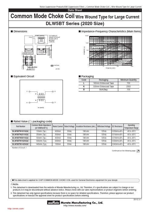
Operating
(at 100MHz/20°C)
Temperature Range
DLW5BTN101SQ2p DLW5BTN251SQ2p DLW5BTN501SQ2p DLW5BTN102SQ2p DLW5BTN142SQ2p Number of Circuit: 1
100ohm (Typ.) 250ohm (Typ.) 500ohm (Typ.) 1000ohm (Typ.) 1400ohm (Typ.)
Noise Suppression Products/EMI Suppression Filters > Common Mode Choke Coil > Wire Wound Type for Large Current
Data Sheet
1
Common Mode Choke Coil Wire Wound Type for Large Current
2012.3.1
/
/
Noise Suppression Products/EMI Suppression Filters > Common Mode Choke Coil > Wire Wound Type for Large Current
0.5 min. (L) 5.0±0.3
0.45 min. (T) 2.35±0.15
1.3±0.3
1.7±0.3
(4) (3) 1.3±0.3 0.9±0.3
: Electrode (in mm)
c Impedance-Frequency Characteristics (Main Items)
10000 Common mode
Notice Solderability of Tin plating termination chip might be deteriorated when low temperature soldering profile where peak solder temperature is below the Tin melting point is used. Please confirm the solderability of Tin plating termination chip before use.
250V22000uF电容的铝电解电容器
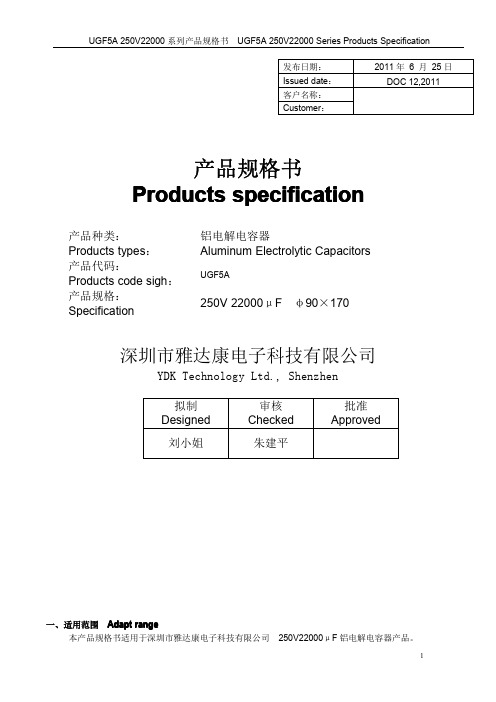
发布日期:2011年6月25日Issued date:DOC12,2011客户名称:Customer:产品规格书Products specification产品种类:铝电解电容器Products types:Aluminum Electrolytic Capacitors产品代码:UGF5AProducts code sigh:产品规格:250V22000μFφ90×170Specification深圳市雅达康电子科技有限公司YDK Technology Ltd.,Shenzhen拟制Designed审核Checked批准Approved刘小姐朱建平一、适用范围Adapt range本产品规格书适用于深圳市雅达康电子科技有限公司250V22000μF铝电解电容器产品。
The products specification is adapted to 250V22000μF Aluminum Electrolytic Capacitors ofYDK Technology Ltd.,Shenzhen二、技术性能Specifications项目Item 特性Performance characteristics使用温度范围(℃)Operation temperature range-40~+105额定电压(V)Rated voltage 250浪涌电压(V)Surge voltage 300标称电容量(μF)Nominal capacitance 22000标称电容量允许偏差(%)Capacitance tolerance±20%漏电流(mA)Leakage current(at 20℃,afer 5minutes)5损耗角正切值(tg δ)Dissipation factor (20℃,120Hz)0.25Ripple current (105℃120Hz)(Arms)56耐久性(105℃)Load life5000小时5000hours三、外形图及尺寸表Case size table(mm )四、纹波电流修正系数ripple current multipliers:频率修正系数Frequency Coefficient 温度修正系数Temperature coefficientφD ±0.7889L ±1.57170F ±0.4131.75频率Freq (Hz)50\601203001K ≥10K 系数factor0.81.001.101.301.40五、试验方法及要求Tests项目Item试验条件Test conditions性能要求Requirements浪涌电压Surge voltage 温度+15~+35℃,施加规定的浪涌电压,充电30秒,放电5分30秒,共循环1000次。
人民电器 二级配电选型手册 RDM10系列塑料外壳式断路器 产品资料说明书

完善的产业链和个性化解决方案,满足全球客户的不同需求!人民电器集团是人民控股集团全资公司,中国500强企业之一,始创于1986年。
人民电器集团以工业电器为核心产业,拥有浙江、上海、南昌、抚州、枣庄、合肥六大制造基地、35家全资子公司150家控股成员企业、1500多家加工协作企业和5000多家销售公司。
产品畅销全球125个国家和地区,广泛应用于浦东机场、京沪高铁、三峡水电、北京地铁、奥运场馆南水北调、青藏铁路、嫦娥探月工程、越南太安水电枢纽等国内外重大工程项目,位居世界机械企业500强前列。
2023年,经世界品牌实验室测评,品牌价值788.15亿。
公司简介COMPANY PROFILE更 安 全保障人员生命及财产安全。
更 可 靠不间断供应电力,全天随时可用。
更 高 效降低能源消耗和成本,提高生产率,缩短需求供应时间。
优化机械、工厂流程,提高使用舒适性。
更 经 济更 环 保通过可再生能源提供能量,减少二氧化碳排放量。
电力与能源电力石油石化交通工业与机器矿业/建材水利/水处理汽车数据中心IT高科技互联网商业网络银行保险金融机构电信运营楼宇办公楼宇工业建筑基础设施住宅住宅建设公共建设小区设施剩余电流保护断路器逆变器直流断路器直流塑壳断路器直流框架断路器光伏箱变直流熔断器直流浪涌保护器终端新能源HS11FH系列防护型开启式刀开关B -117HD11F系列防误型开启式刀开关B -119RDM1系列塑料外壳式断路器B -001RDM10系列塑料外壳式断路器B -010DZ20系列塑料外壳式断路器B -015DZ15系列塑料外壳式断路器B -020RDM1E系列电子式塑壳断路器B -023RDM1L系列漏电断路器B -043RDL20系列漏电断路器B -057DZL25系列漏电断路器B -064DZ15LE系列漏电断路器B -060RDL18系列漏电断路器B -068RDWQ2系列双电源自动转换开关B -080RDQ6系列双电源自动转换开关B -082RDH5D系列双电源自动转换开关B -088HD 、HS系列开启式刀开关B -101RDQH系列双电源自动转换开关B -070RDQ1系列双电源自动转换开关B -077HD11FH系列防护型开启式刀开关B -121RDH5系列隔离开关B -123HR3系列熔断器式刀开关B -130HR5系列熔断器式隔离开关B -133RDH5DS系列双电源自动转换开关B -096RDM1EL系列电子式塑壳断路器B -051HR17B系列熔断器隔离开关B -141RDT16系列有填料封闭管式刀型触头熔断器B -155HH15系列隔离开关熔断器组B -146RDH5R系列隔离开关熔断器组B -143NGT系列快速熔断器B -174RS0、RS3系列快速熔断器B -171RT0系列有填料封闭管式刀型触头熔断器B -168RT14系列有填料封闭式管圆筒形帽熔断器B -165HG30熔断器式隔离器B -163RT18系列有填料封闭管式圆筒形帽熔断器B -160HR6系列熔断器式隔离开关B -136RDHG2B系列条型熔断器式隔离开关B -139全国统一客服热线: 400 898 1166 001选型指南产品概述RDM1系列塑料外壳式断路器具有体积小、分断能力高、飞弧短、抗震动的特点, 是陆地及船舶使用的理想产品。
DK125规格书
功能描述DK125是次级反馈,反激式AC-DC 离线式开关电源控制芯片。
芯片采用高集成度的CMOS 电路设计,具有输出短路、次级开路、过温、过压等保护功能。
芯片内置高压功率管和自供电线路,具有外围元件极少,变压器设计简单(变压器不需要供电绕组)等特点。
产品特点l 全电压输入90V —264V 。
l 内置700V 功率管。
l 芯片内集成了高压恒流启动电路,无需外部启动电阻。
l 专利的自供电技术,无需外部绕组供电。
l 待机功耗小于0.3W 。
l 65KHz PWM 开关频率。
l 内置变频功能,待机时自动降低工作频率,在满足欧洲绿色能源标准(<0.3W )同时,降低了输出电压的纹波。
l 内置斜坡补偿电路,保证在低电压及大功率输出时的电路稳定。
l 频率抖动降低EMI 滤波成本。
l 过温、过流、过压以及输出短路,次级开路保护。
l4KV 防静电ESD 测试。
应用领域24W 以下AC-DC 应用包括:电源适配器、LED 电源、电磁炉、空调、DVD 、机顶盒等家电产品。
深圳东科半导体有限公司封装与引脚定义(DIP8)内部框图引脚符号功能描述1GND 接地引脚2GND 接地引脚3FB反馈控制端引脚,接1nF ~10nF4VCC 供电引脚,外部对地接47uF ~100uF 的电容5,6,7,8OC输出引脚,连接芯片内高压功率管,外部与开关变压器相连深圳东科半导体有限公司极限参数供电电压VDD ………………………………………………………-0.3V--8V 供电电流VDD ………………………………………………………100mA引脚电压………………………………………………………-0.3V--VDD+0.3V 功率管耐压………………………………………………………-0.3V--700V 峰值电流………………………………………………………1300mA总耗散功率………………………………………………………1000mW工作温度………………………………………………………-25°C--+125°C 储存温度………………………………………………………-55°C--+150°C 焊接温度………………………………………………………+280°C/5S电气参数项目测试条件最小典型最大单位VCC 工作电压AC 输入85V-----265V 4.54.7 4.9V VCC 启动电压AC 输入85V-----265V 4.7V VCC 重启电压AC 输入85V-----265V 3.30 3.60 3.90V VCC 保护电压AC 输入85V-----265V 6.25 6.55 6.85V VCC 工作电流VCC=5V ,FB=1.5V 50mA 高压启动电流AC 输入85V-----265V0.30.6 1.2mA 启动时间AC 输入85V ------500mS 功率管耐压Ioc=1mA 700------V 功率管保护电压测量OC 电压540600660V 最大峰值电流VCC=5V ,FB=1.5V---2.8V 110012001300mA PWM 输出频率VCC=5V ,FB=1.5V---2.5V 616569KHz VCC=5V ,FB=2.5v-2.8v202224KHz 调制步进频率VCC=5V ,FB=1.5v-2.5v0.5KHz 短路保护阀值测量FB 电压 1.15 1.33 1.50V 变频阀值电压测量FB 电压 2.3 2.5 2.7V 突发模式阀值测量FB 电压2.6 2.83.0V温度保护结温120130140℃深圳东科半导体有限公司前沿消隐时间VCC=5V ,FB=1.5v-2.5v 250ns最小开通时间VCC=5V ,FB=2.6v 500ns 占空比VCC=5V ,FB=1.5v-2.5v 5---70%待机功耗AC 输入265V,空载270mW功能描述上电启动上电启动时,芯片通过内部连接OC 和VCC 引脚的高压电流源,对外部的VCC 储能电容充电,当VCC 电压升高到4.7V 的时候,关闭高压电流源,启动过程结束,控制逻辑开始输出PWM 脉冲。
夏普二代GP2Y1050AU 原厂规格书 日文版 完整版(灰尘传感器规格书-修订版20140226)
記号/Symbol 定格/Rating
Vcc
4.8~5.2
VLED -0.3 ~ Vcc
Topr -10 ~ +65
Tstg -20 ~ +80
単 位 /Unit
V V ℃ ℃
(Ta=25℃) 備 考/Remark
Sensor apply voltage Open drain drive input
項目/Item
内容/Detail
AQL(%)
重欠点
2.3 電気的光学的特性
0.4
/ major defect 2.3 Electrical optical characteristic
軽欠点
Appearance and dimension
/minor defect
(注意点)/ 注意点 ① お客様が本仕様書の内容に基づき、お客様の商品のカタログ、取扱い説明書等を
作成される場合には、本製品をお客様の商品に組み込んだ状態で、その合理的根拠の有無を ご検証頂きますようお願い致します。 /(1) 当客户根据本规格书,来制作客户的商品目录、使用说明书时,须在本产品组装于客户的 商品中的状态下,来检验是否有合理的依据。
○ 本製品につきご不明な点がありましたら事前に弊社販売窓口までご連絡頂きますようお願い致します。 /如对本产品有不明点烦请事先联系我司销售窗口。
目次/目录
1.一般事項/常规信息 1.1 適用範囲/适用范围 1.2 主な機能/主要功能 1.3 回路図/电路图
2.一般性能/一般性能 2.1 絶対最大定格/绝对最大额定 2.2 電気的光学特性/电器光学特性 2.3 電圧特性/电压特性
③ 機能・精度等において高い信頼性・安全性が必要とされる下記の用途に本製品を使用 される場合は、これらの機器の信頼性および安全性維持のためにフェールセーフ設計や 冗長設計の措置を講じる等、システム・機器全体の安全設計にご配慮頂いた上で本製品を ご使用下さい。 ・ 運送機器(航空機、列車、自動車等)の制御と各種安全性にかかわるユニット ・ 交通信号機 ・ ガス漏れ検知遮断器 ・ 防災防犯装置 ・ 各種安全装置 等
红杉设备安装手册
MacroSAN MS2510/MS2520系列存储设备安装手册文档版本:V1.01杭州宏杉科技有限公司400-650-5527声明Copyright © 2010杭州宏杉科技有限公司及其许可者版权所有,保留一切权利。
未经杭州宏杉科技有限公司书面许可,任何单位和个人不得擅自摘抄本手册的内容,且不得以任何形式传播本手册。
本手册仅作为操作参考,由于软件版本升级或其他原因,本手册的内容可能滞后于最新的软件版本,杭州宏杉科技有限公司保留在没有任何通知或提示的情况下对本手册的内容进行修改的权利。
商标信息MacroSAN、ODSP、ODSP_MSC、ODSP_JMC、ODSP Scope、宏杉均为杭州宏杉科技有限公司的商标。
对于本手册中出现的其他公司的商标、产品标识及商品名称,由各自权利人拥有。
目录MacroSAN MS2510/MS2520系列存储设备 ........................................................................................... 1-1安装手册.................................................................................................................................................. 1-1声明.......................................................................................................................................................... 1-2商标信息 .................................................................................................................................................. 1-2目录.......................................................................................................................................................... 1-3图目录...................................................................................................................................................... 1-8表目录.................................................................................................................................................... 1-11 1前言..................................................................................................................................................... 1-131.1 读者对象.......................................................................................................................................... 1-131.2 适用范围.......................................................................................................................................... 1-131.3 文档结构.......................................................................................................................................... 1-131.4 文档约定.......................................................................................................................................... 1-141.4.1 手册描述约定........................................................................................................................ 1-141.4.2 其他约定 ............................................................................................................................... 1-141.5 术语................................................................................................................................................. 1-141.5.1 DSU ...................................................................................................................................... 1-141.5.2 EP ......................................................................................................................................... 1-151.5.3 FC ......................................................................................................................................... 1-151.5.4 GE ........................................................................................................................................ 1-151.5.5 GUI ....................................................................................................................................... 1-151.5.6 iSCSI .................................................................................................................................... 1-151.5.7 ODSP ................................................................................................................................... 1-151.5.8 ODSP Scope ........................................................................................................................ 1-151.5.9 SAN ...................................................................................................................................... 1-151.5.10 SAS .................................................................................................................................... 1-151.5.11 SATA .................................................................................................................................. 1-151.5.12 SP ....................................................................................................................................... 1-161.5.13 SPU .................................................................................................................................... 1-161.5.14 SSD .................................................................................................................................... 1-161.6 资料获取方式................................................................................................................................... 1-161.7 资料意见或建议反馈方式................................................................................................................. 1-16 2安全注意事项 ...................................................................................................................................... 2-162.1 通用安全注意事项 ........................................................................................................................... 2-162.2 用电安全注意事项 ........................................................................................................................... 2-172.3 静电安全注意事项 ........................................................................................................................... 2-172.4 激光安全注意事项 ........................................................................................................................... 2-172.5 电池安全注意事项 ........................................................................................................................... 2-172.6 磁盘使用注意事项 ........................................................................................................................... 2-182.7 搬运注意事项................................................................................................................................... 2-19 3产品介绍 ............................................................................................................................................. 3-193.1 产品概述.......................................................................................................................................... 3-193.2 产品规格.......................................................................................................................................... 3-203.2.1 SPU规格 .............................................................................................................................. 3-203.2.2 DSU规格.............................................................................................................................. 3-223.2.3 磁盘模块规格........................................................................................................................ 3-223.3 产品外观.......................................................................................................................................... 3-233.3.1 SPU外观 .............................................................................................................................. 3-233.3.2 DSU外观.............................................................................................................................. 3-293.3.3 电源模块外观........................................................................................................................ 3-323.3.4 磁盘模块外观........................................................................................................................ 3-333.4 产品指示灯 ...................................................................................................................................... 3-343.4.1 SP指示灯 ............................................................................................................................. 3-343.4.2 EP指示灯 ............................................................................................................................. 3-353.4.3 电源模块指示灯 .................................................................................................................... 3-353.4.4 风扇模块指示灯 .................................................................................................................... 3-363.4.5 电池模块指示灯 .................................................................................................................... 3-363.4.6 磁盘模块指示灯 .................................................................................................................... 3-36 4安装设备 ............................................................................................................................................. 4-374.1 安装规划.......................................................................................................................................... 4-374.2 安装流程.......................................................................................................................................... 4-374.3 安装前准备 ...................................................................................................................................... 4-384.3.1 准备安装场所........................................................................................................................ 4-384.3.2 准备机柜 ............................................................................................................................... 4-414.3.3 准备安装工具........................................................................................................................ 4-424.4 安装前检查 ...................................................................................................................................... 4-434.4.1 检查环境 ............................................................................................................................... 4-434.4.2 检查设备 ............................................................................................................................... 4-444.4.3 检查磁盘模块........................................................................................................................ 4-454.4.4 检查线缆 ............................................................................................................................... 4-454.5 安装机柜.......................................................................................................................................... 4-464.5.1 安装机柜 ............................................................................................................................... 4-464.5.2 安装机柜后检查 .................................................................................................................... 4-464.6 安装托架式滑道............................................................................................................................... 4-464.6.1 托架式滑道介绍 .................................................................................................................... 4-464.6.4 安装滑道后检查 .................................................................................................................... 4-494.7 安装SPU ......................................................................................................................................... 4-494.7.1 安装SPU流程 ...................................................................................................................... 4-494.7.2 安装SPU到机柜中............................................................................................................... 4-504.7.3 安装电池模块........................................................................................................................ 4-514.7.4 安装SPU面板 ...................................................................................................................... 4-524.7.5 安装SPU后检查 .................................................................................................................. 4-534.8 安装DSU ......................................................................................................................................... 4-534.8.1 安装DSU流程...................................................................................................................... 4-534.8.2 安装DSU到机柜中............................................................................................................... 4-544.8.3 安装DSU后检查 .................................................................................................................. 4-554.9 安装磁盘模块................................................................................................................................... 4-554.9.1 安装磁盘模块流程................................................................................................................. 4-554.9.2 安装SPU的磁盘模块 ........................................................................................................... 4-564.9.3 安装DSU1516/DSU1616的磁盘模块 .................................................................................. 4-574.9.4 安装DSU1525磁盘模块....................................................................................................... 4-584.9.5 安装磁盘假面板 .................................................................................................................... 4-594.9.6 安装磁盘模块后检查............................................................................................................. 4-604.10 安装线缆........................................................................................................................................ 4-604.10.1 布线注意事项...................................................................................................................... 4-604.10.2 安装线缆的流程 .................................................................................................................. 4-634.10.3 安装接地线.......................................................................................................................... 4-644.10.4 安装电源线.......................................................................................................................... 4-654.10.5 安装SAS线缆 .................................................................................................................... 4-674.10.6 安装SP业务接口线缆 ........................................................................................................ 4-714.10.7 安装SP管理网口线缆 ........................................................................................................ 4-734.10.8 安装客户端服务器的线缆.................................................................................................... 4-734.10.9 安装线缆后检查 .................................................................................................................. 4-73 5启动与配置设备 .................................................................................................................................. 5-745.1 设备上电前检查............................................................................................................................... 5-745.2 设备上电及启动............................................................................................................................... 5-745.2.1 DSU上电及启动 ................................................................................................................... 5-745.2.2 DSU启动后检查 ................................................................................................................... 5-755.2.3 SPU上电及启动 ................................................................................................................... 5-755.2.4 SPU启动后检查 ................................................................................................................... 5-755.3 设备配置.......................................................................................................................................... 5-765.3.3 设备配置 ............................................................................................................................... 5-775.4 设备关机及下电............................................................................................................................... 5-79 6安装与拆卸设备组件 ........................................................................................................................... 6-796.1 安装/拆卸SP ................................................................................................................................... 6-806.1.1 SP介绍................................................................................................................................. 6-806.1.2 安装SP ................................................................................................................................. 6-806.1.3 拆卸SP ................................................................................................................................. 6-816.2 安装/拆卸EP ................................................................................................................................... 6-816.2.1 EP介绍................................................................................................................................. 6-816.2.2 安装EP ................................................................................................................................. 6-826.2.3 拆卸EP ................................................................................................................................. 6-826.3 安装/拆卸电源模块 .......................................................................................................................... 6-836.3.1 电源模块介绍........................................................................................................................ 6-836.3.2 安装电源模块........................................................................................................................ 6-846.3.3 拆卸电源模块........................................................................................................................ 6-846.4 安装/拆卸SPU风扇模块 ................................................................................................................. 6-846.4.1 SPU风扇模块介绍................................................................................................................ 6-846.4.2 安装SPU风扇模块............................................................................................................... 6-856.4.3 拆卸SPU风扇模块............................................................................................................... 6-856.5 安装/拆卸DSU风扇模块................................................................................................................. 6-866.5.1 DSU风扇模块介绍................................................................................................................ 6-866.5.2 安装DSU风扇模块............................................................................................................... 6-866.5.3 拆卸DSU风扇模块............................................................................................................... 6-866.6 安装/拆卸电池模块 .......................................................................................................................... 6-876.6.1 电池模块介绍........................................................................................................................ 6-876.6.2 安装电池模块........................................................................................................................ 6-876.6.3 拆卸电池模块........................................................................................................................ 6-886.7 安装/拆卸磁盘模块 .......................................................................................................................... 6-886.7.1 磁盘模块介绍........................................................................................................................ 6-886.7.2 安装磁盘模块........................................................................................................................ 6-896.7.3 拆卸磁盘模块........................................................................................................................ 6-89 7常见故障处理 ...................................................................................................................................... 7-907.1 SP故障处理 .................................................................................................................................... 7-907.1.1 故障现象1:SP的告警指示灯闪烁或常亮 ........................................................................... 7-907.1.2 故障现象2:SP的运行指示灯常亮或常灭 ........................................................................... 7-917.1.3 故障现象3:SP启动过程中,LED数码管无法显示信息..................................................... 7-917.1.4 故障现象4:SP启动过程中,LED数码管停留在88 ........................................................... 7-917.1.5 故障现象5:SP启动过程中,LED数码管长时间停留在某个固定值................................... 7-927.2 EP故障处理 .................................................................................................................................... 7-927.2.1 故障现象1:告警指示灯闪烁或常亮 .................................................................................... 7-927.2.2 故障现象2:运行指示灯常亮或常灭 .................................................................................... 7-927.3 电源模块故障处理 ........................................................................................................................... 7-937.4 风扇模块故障处理 ........................................................................................................................... 7-947.5 电池模块故障处理 ........................................................................................................................... 7-947.6 其他故障处理................................................................................................................................... 7-94 8附录A.拇指螺钉的安装方法................................................................................................................ 8-95图目录图3-1 SPU前正视图 ............................................................................................................................. 3-23图3-2 SPU后正视图 ............................................................................................................................. 3-24图3-3 MS2510f/MS2520f的SP正视图................................................................................................ 3-25图3-4 MS2510i/MS2520i的SP正视图 ................................................................................................ 3-26图3-5 SPU风扇模块正视图 .................................................................................................................. 3-28图3-6 电池模块正视图 .......................................................................................................................... 3-28图3-7 DSU1516/DSU1616前正视图.................................................................................................... 3-29图3-8 DSU1525前正视图..................................................................................................................... 3-29图3-9 DSU1516后正视图..................................................................................................................... 3-30图3-10 DSU1516的EP正视图 ............................................................................................................ 3-31图3-11 DSU风扇模块正视图................................................................................................................ 3-32图3-12 电源模块正视图 ........................................................................................................................ 3-33图3-13 3.5英寸磁盘模块前面板 ........................................................................................................... 3-33图3-14 2.5英寸磁盘模块前面板 ........................................................................................................... 3-33图4-1 存储设备的安装规划示意图 ........................................................................................................ 4-37图4-2 存储设备的安装流程示意图 ........................................................................................................ 4-38图4-3 设备防拆封条示意图 ................................................................................................................... 4-45图4-4 托架式滑道(左侧滑道)示意图................................................................................................. 4-47图4-5 确定托架式滑道安装位置示意图................................................................................................. 4-47图4-6 安装左侧滑道示意图 ................................................................................................................... 4-48图4-7 安装拇指螺钉示意图 ................................................................................................................... 4-48图4-8 检查滑道示意图 .......................................................................................................................... 4-49图4-9 SPU安装流程示意图 .................................................................................................................. 4-50图4-10 安装SPU示意图....................................................................................................................... 4-51图4-11 检查SPU示意图....................................................................................................................... 4-51图4-12 安装电池模块示意图 ................................................................................................................. 4-52图4-13 安装SPU面板示意图 ............................................................................................................... 4-53图4-14 DSU安装流程示意图................................................................................................................ 4-54图4-15 安装DSU示意图 ...................................................................................................................... 4-54图4-16 检查DSU示意图 ...................................................................................................................... 4-55图4-17 磁盘模块安装流程图 ................................................................................................................. 4-56图4-18 SPU磁盘槽位编号示意图......................................................................................................... 4-56图4-19 3.5英寸磁盘模块示意图 ........................................................................................................... 4-57图4-21 DSU1516/DSU1616磁盘槽位编号示意图................................................................................ 4-58图4-22 DSU1525磁盘槽位编号示意图................................................................................................. 4-58图4-23 2.5英寸磁盘模块示意图 ........................................................................................................... 4-59图4-24 安装2.5英寸磁盘模块示意图................................................................................................... 4-59图4-25 安装磁盘假面板示意图.............................................................................................................. 4-60图4-26 固定线缆端子示意图 ................................................................................................................. 4-61图4-27 线缆捆扎示意图(一).............................................................................................................. 4-62图4-28 线缆捆扎示意图(二).............................................................................................................. 4-62图4-29 线缆捆扎示意图(三).............................................................................................................. 4-63图4-30 线缆安装流程示意图 ................................................................................................................. 4-63图4-31 接地线示意图 ............................................................................................................................ 4-64图4-32 松开设备接地端子的螺钉示意图............................................................................................... 4-64图4-33 安装接地线示意图..................................................................................................................... 4-65图4-34 电源线示意图 ............................................................................................................................ 4-65图4-35 安装电源线示意图..................................................................................................................... 4-66图4-36 电源线捆扎示意图..................................................................................................................... 4-66图4-37 Mini SAS线缆示意图................................................................................................................ 4-67图4-38 Mini SAS连接器(线缆端)示意图.......................................................................................... 4-68图4-39 高速SAS线缆弯曲半径示意图................................................................................................. 4-69图4-40 SAS线缆连接示意图 ................................................................................................................ 4-70图4-41 以太网线缆和接口示意图.......................................................................................................... 4-71图4-42 FC线缆和接口示意图 ............................................................................................................... 4-72图5-1 加载ODSP Scope界面.............................................................................................................. 5-77图5-2 ODSP Scope设备管理界面........................................................................................................ 5-78图5-3 设备初始配置流程示意图............................................................................................................ 5-79图6-1 安装/拆卸SP示意图................................................................................................................... 6-80图6-2 安装/拆卸EP示意图................................................................................................................... 6-82图6-3 安装/拆卸DSU电源模块示意图 ................................................................................................. 6-83图6-4 安装/拆卸SPU风扇模块示意图.................................................................................................. 6-85图6-5 安装/拆卸DSU风扇模块示意图 ................................................................................................. 6-86图6-6 安装/拆卸电池模块示意图........................................................................................................... 6-87图6-7 安装/拆卸3.5英寸磁盘模块示意图............................................................................................. 6-89图6-8 安装/拆卸2.5英寸磁盘模块示意图............................................................................................. 6-89图8-1 拇指螺钉示意图 .......................................................................................................................... 8-95。
MBRA140T3G;MBRA140T3;中文规格书,Datasheet资料
Figure 5. Current Derating
R (T) , TRANSIENT THERMAL RESISTANCE (NORMALIZED) T, TIME (s) 1.0E+0
Figure 6. Forward Power Dissipation
中文规格书datasheet资料datasheetdatasheet网站l298ndatasheeticdatasheetpl2303datasheetds18b20datasheetdatasheetcomlm324datasheetrt5350datasheet
MBRA140T3G, NRVBA140T3G Surface Mount Schottky Power Rectifier
vF, INSTANTANEOUS FORWARD VOLTAGE (VOLTS)
Figure 1. Typical Forward Voltage
Figure 2. Maximum Forward Voltage
100E-3 I R , REVERSE CURRENT (AMPS)
100E-3 I R , MAXIMUM REVERSE CURRENT (AMPS)
†For information on tape and reel specifications, including part orientation and tape sizes, please refer to our Tape and Reel Packaging Specifications Brochure, BRD8011/D.
10E-3
TJ = 125C TJ = 85C
10E-3 TJ = 85C 1.0E-3 TJ = 25C
FGA25N12ANTD资料
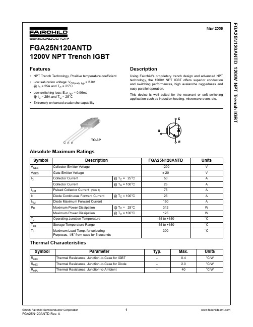
FGA25N120ANTD 1200V NPT Trench IGBT
元器件交易网
20 Common Emitter TC = 125°C
16
Collector-Emitter Voltage, VCE [V]
12
8
40A 25A 4
IC = 12.5A
0
0
4
8
12
16
20
Gate-Emitter Voltage, VGE [V]
4 FGA25N120ANTD Rev. A
--
--
3
mA
--
--
± 250
nA
3.5
5.5
7.5
V
--
2.0
2.5
V
--
2.15
--
V
--
2.65
--
V
--
3700
--
pF
--
130
--
pF
--
80
--
pF
--
50
--
ns
--
60
--
ns
--
190
--
ns
--
100
--
ns
--
4.1
--
mJ
--
0.96
--
mJ
-
50
--
1200 ± 20 50 25 75 25 150 312 125 -55 to +150 -55 to +150 300
Typ.
----
Max.
0.4 2.0 40
Units
V V A A A A A W W °C °C °C
夏普公司GP2A25J0000F系列光电隔离器说明书
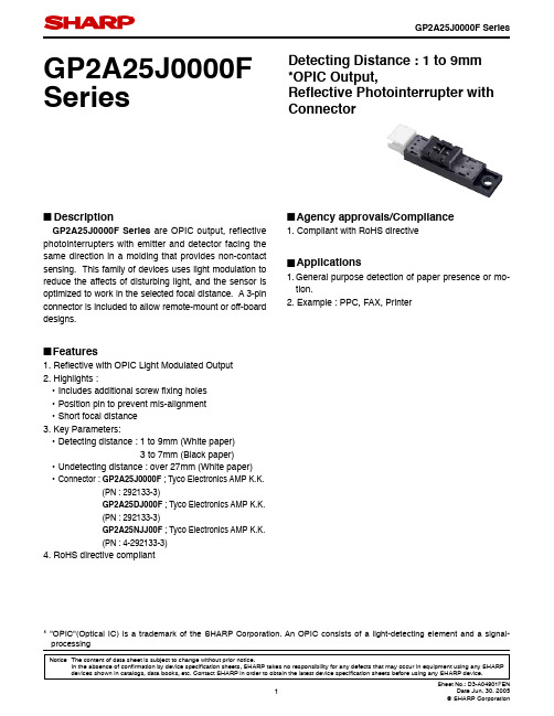
Notice The content of data sheet is subject to change without prior notice.In the absence of con fi rmation by device speci fi cation sheets, SHARP takes no responsibility for any defects that may occur in equipment using any SHARP GP2A25J0000F SeriesDetecting Distance : 1 to 9mm *OPIC Output, Re fl ective Photointerrupter with Connector■DescriptionGP2A25J0000F Series are OPIC output, reflective photointerrupters with emitter and detector facing the same direction in a molding that provides non-contact sensing. This family of devices uses light modulation to reduce the affects of disturbing light, and the sensor is optimized to work in the selected focal distance. A 3-pin connector is included to allow remote-mount or off-board designs.■Features1. Re fl ective with OPIC Light Modulated Output2. Highlights :• Includes additional screw fi xing holes • Position pin to prevent mis-alignment • Short focal distance 3. Key Parameters:• Detecting distance : 1 to 9mm (White paper) 3 to 7mm (Black paper)• Undetecting distance : over 27mm (White paper) • Connector : GP2A25J0000F ; Tyco Electronics AMP K.K. (PN : 292133-3) GP2A25DJ000F ; Tyco Electronics AMP K.K. (PN : 292133-3) GP2A25NJJ00F ; Tyco Electronics AMP K.K. (PN : 4-292133-3)4. RoHS directive compliant■Agency approvals/Compliance1. Compliant with RoHS directive■Applications1. General purpose detection of paper presence or mo-tion.2. Example : PPC, FAX, Printer* "OPIC"(Optical IC) is a trademark of the SHARP Corporation. An OPIC consists of a light-detecting element and a signal-processing■Internal Connection Diagram■Outline Dimensions(Unit : mm)V CC V OUT GNDDate code (2 digit)1st digit2nd digit Year of production Month of production A.D.Mark Month Mark 2000011 2001122 2002233 2003344 2004455 2005566 2006677 2007788 2008899 2009910X 2010011Y ::12Zrepeats in a 10 year cycleCountry of originJapan■Absolute Maximum Ratings■Electro-optical Characteristics (T a=25˚C)Parameter Symbol Rating UnitSupply voltage V CC−0.5 to +7VOutput voltage V O30V*1 Output current I OL50mA*2 Operating temperature T opr−10 to +60˚C*2 Storage temperature T stg−20 to +80˚C∗1 Sink current refer to Fig.5.∗2 The connector should be plugged in/out at normal temperature.(T a=25˚C) Parameter Symbol Condhitions MIN.TYP.MAX.Unit Supply voltage V CC− 4.75− 5.25V Current dissipation (I)I CC Smoothing value V CC=5V, R L=∞−−30mA *3 Current dissipation (II)I CCP Pulse peak value V CC=5V−−150mA Low level output voltage V OL V CC=5V, I OL=16mA, at detecting time−−0.4V High level output voltage V OH V CC=5V, R L=1kΩ, at non detecting time 4.5−−V*4 Non detection distance L LHL KODAK Gray Cards, V CC=5V−−27mm*4 Detection distance L HLSKODAK Gray Cards, V CC=5V−−1mm Black paper, V CC=5V−−3L HLLKODAK Gray Cards, V CC=5V9−−mm Black paper, V CC=5V7−−*5 Response time t PLHV CC=5V−−1ms t PHL−−1ms*6 Acceptable illuminance Ev1−3 000−−lx Ev2 1 500−−lx∗3 Refer to Fig.1.∗4 Refer to Fig.2.∗5 Refer to Fig.3.*6 Refer to Fig.4.Refl ective object Black paper (black) : Standard refl ective object (provided by SHARP Corporation) KODAK Gray Cards (use the white side refl ects about 90%):Standardrefl ective object (provided by SHARP Corporation) PPC paper : Standard refl ective object (provided by SHARP Corporation)Fig.2 Test Condition for Detecting Distance CharacteristicsV OHV OLLHS LHLO u t p u t V ODetection surfaceFig.1 Test Condition for Peak Pulse Value I CCPV O GNDμs W sV CC =5V L =1k ΩFig.3 Test Circuit for Response TimeV O GNDV V CC =5V Reflective objectWithout reflective objectE V1 : At non-detectingE V2 : At detectingIlluminance shall be that on the emission/detection surface. Output shall not go from "H" to "L".Light source A PhotointerrupterFig.4 Test Condition for External Disturbing Light IlluminanceFig.5 Low Level Output Current vs. Ambient TemperatureFig.6 Low Level Output Voltage vs. Ambient Temperature6050403020100L o w l e v e l o u t p u t c u r r e n t I O L (m A )27Low level output current I OL (mA)L o w l e v e l o u t p u t v o l t a g e V O L (V )0.010.1Supply voltage V CC (V)Remarks : Please be aware that all data in the graph are just for reference and not for guarantee.■Design Considerations●Design guide1) V O terminal : Open collector outputThis product operates the light emitter by pulse drive. Please supply the stable supply voltage in order to prevent error operation by pulse current.Please use this device after connecting a capacitor between V O and GND for prevention of line noise.2) Prevention of detection errorPlease be careful that you need to keep the direct inverter light away from the photo detecting surface since the device will not operate correctly in such case.In addition, we recommend to make sure the operation test in the actual application.3) Plugging in/outThe connector should be plugged in/out at normal temperature.This product is not designed against irradiation and incorporates non-coherent IRED.●PartsThis product is assembled using the below parts.• Photodetector (Q'ty : 1) [Using a silicon photodiode as light detecting portion, and a bipolar IC as signal processing circuit]Category Maximum Sensitivitywavelength (nm)Sensitivitywavelength (nm)Response time (μs)Photo diode900700 to 1 200400• Photo emitter (Q'ty : 1)Category Material Maximum light emittingwavelength (nm)I/O Frequency (MHz)Infrared emitting diode(non-coherent)Gallium arsenide (GaAs)9500.3 • MaterialCase Lens Bottom cover GP2A25J0000FBlack polyphernylene Sulfi de resin (UL94 V-0)Acryl resin(UL94 HB)Polycarbonate resin (Black) (UL94 V-2)GP2A25DJ000J Polycarbonate resin (Black) (UL94 V-2) GP2A25NJJ00F∗Polycarbonate resin (Black) (UL94 V-2)∗The IR-90 fi lter (Fuji Photo Film Co., Ltd.) is inserted between case and detector side lens.• OthersLaser generator is not used.■Manufacturing Guidelines●Cleaning instructionsPolycarbonate resin is used as the material of the lens surface. So this product shall not be cleaned by cleaning solvent absolutely. Dust and stain shall clean by air blow, or shall clean by soft cloth.●Presence of ODCThis product shall not contain the following materials.And they are not used in the production process for this product.Regulation substances : CFCs, Halon, Carbon tetrachloride, 1.1.1-Trichloroethane (Methylchloroform)Specifi c brominated fl ame retardants such as the PBBOs and PBBs are not used in this product at all.This product shall not contain the following materials banned in the RoHS Directive (2002/95/EC).•Lead, Mercury, Cadmium, Hexavalent chromium, Polybrominated biphenyls (PBB), Polybrominateddiphenyl ethers (PBDE).■Package specifi cation●Case packagePackage materialsAnti-static plastic bag : PolyethtyleneMoltopren : UrethanePacking case : Corrugated fi berboardPackage method100 pcs of products shall be packaged in a plastic bag, Ends shall be sealed by stapler. The bottom ot the packing case is covered with moltopren, and 2 plastic bags shall be put int the packing case.Moltopren should be located after all product are settled (1 packing conteains 200 pcs).Packing composition■Important Notices· The circuit application examples in this publication are provided to explain representative applications of SHARP devices and are not intended to guarantee any circuit design or license any intellectual property rights. SHARP takes no responsibility for any problems related to any intellectual property right of a third party resulting from the use of SHARP's devices.· Contact SHARP in order to obtain the latest device specification sheets before using any SHARP device. SHARP reserves the right to make changes in the specifi cations, characteristics, data, materials, structure, and other contents described herein at any time without notice in order to improve design or reliability. Manufacturing locations are also subject to change without notice.· Observe the following points when using any devices in this publication. SHARP takes no responsibility for damage caused by improper use of the devices which does not meet the conditions and absolute maximum ratings to be used specifi ed in the relevant specifi cation sheet nor meet the following conditions:(i) The devices in this publication are designed for use in general electronic equipment designs such as:--- Personal computers--- Offi ce automation equipment--- Telecommunication equipment [terminal]--- Test and measurement equipment--- Industrial control--- Audio visual equipment--- Consumer electronics(ii) Measures such as fail-safe function and redundant design should be taken to ensure reliability and safety when SHARP devices are used for or in connection with equipment that requires higher reliability such as:--- Transportation control and safety equipment (i.e., aircraft, trains, automobiles, etc.)--- Traffi c signals--- Gas leakage sensor breakers--- Alarm equipment--- Various safety devices, etc.(iii) SHARP devices shall not be used for or in connection with equipment that requires an extremely high level of reliability and safety such as:--- Space applications--- Telecommunication equipment [trunk lines]--- Nuclear power control equipment--- Medical and other life support equipment (e.g., scuba).· If the SHARP devices listed in this publication fall within the scope of strategic products described in the Foreign Exchange and Foreign Trade Law of Japan, it is necessary to obtain approval to export such SHARP devices.· This publication is the proprietary product of SHARP and is copyrighted, with all rights reserved. Under the copyright laws, no part of this publication may be reproduced or transmitted in any form or by any means, electronic or mechanical, for any purpose, in whole or in part, without the express written permission of SHARP. Express written permission is also required before any use of this publication may be made by a third party.· Contact and consult with a SHARP representative if there are any questions about the contents of this publication.。
桑德电气PDG24G0225P2MN产品说明书

Eaton PDG24G0225P2MNEaton Power Defense molded case circuit breaker, Globally Rated, Frame 2, Four Pole (100% N), 225A, 35kA/480V, PXR25 LSI w/ Modbus RTU and Relays, No TerminalsGeneral specificationsEaton Power Defense molded case circuit breakerPDG24G0225P2MN 78667928103188.9 mm 152.4 mm 139.5 mm 2.46 kg Eaton Selling Policy 25-000, one (1) year from the date of installation of theProduct or eighteen (18) months from thedate of shipment of the Product,whichever occurs first.RoHS Compliant IEC 60947-2CCC MarkedUL 489CSAProduct NameCatalog Number UPCProduct Length/Depth Product Height Product Width Product Weight WarrantyCompliancesCertifications225 AComplete breaker 2Four-pole (100% N)PD2 Global Class A PXR 25 LSIModbus RTU600 Vac600 V100% neutral protectionNo Terminals35 kAIC at 480 Vac30 kAIC Icu/ 22.5 kAIC Ics/ 63 kAIC Icm @440V (IEC)10 kAIC Icu @125 Vdc18 kAIC @600V (UL/CSA)8 kAIC Icu/ 4 kAIC Ics/ 16.8 kAIC Icm @690V (IEC)10 kAIC Icu @250 Vdc25 kAIC Icu/ 20 kAIC Ics/ 52.5 kAIC Icm @480V Brazil (IEC) 35 kAIC @480V (UL)65 kAIC @240V (UL)36 kAIC Icu/ 36 kAIC Ics/ 75.6 kAIC Icm @380-415V (IEC)20 kAIC Icu/ 15/13 kAIC Ics/ 42 kAIC Icm @525V South Africa (IEC)55 kAIC Icu/ 55 kAIC Ics/ 121 kAIC Icm @240V (IEC)Eaton Power Defense MCCB PDG24G0225P2MN 3D drawingPower Xpert Protection Manager x64Consulting application guide - molded case circuit breakers Power Xpert Protection Manager x32Power Defense molded case circuit breaker selection poster Power Defense brochurePower Defense technical selling bookletPower Defense molded case circuit breakers - Frame 2 product aid Molded case circuit breakers catalogAmperage RatingCircuit breaker frame type FrameNumber of poles Circuit breaker type ClassTrip Type CommunicationVoltage ratingVoltage rating - maxProtectionTerminalsInterrupt rating Interrupt rating range 3D CAD drawing package Application notesBrochuresCatalogsPower Xpert Release trip units for Power Defense molded case circuit breakersCertification reportsPDG2 CB reportEU Declaration of Conformity - Power Defense molded case circuit breakersPDG4 CB reportPDG4 CCC certificationInstallation instructionsPower Defense Frame 2 PDG2 and PDC(E)9 breaker instructions -IL012106ENPower Defense Frame 2 multi wire connector kit -PDG2X3(2)(4)TA2256W instructions - IL012242EN H01Power Defense Frame 2 screw terminal_end cap kit, 225A, 3 pole instructions - IL012258EN H01Power Defense Frame 2 tunnel terminal (aluminum), 50A, 4 pole instructions - IL012236EN H04Power Defense Frame 2 box terminal (steel), 100A, 4 pole instructions - IL012234EN H04Power Defense Frame 2 terminal kit - PDG2X3(2)(4)TA225RF instructions - IL012245EN H01Power Defense Frame 1 IEC and Frame 2 Rotary Mechanism with NFPA Handle Attachment Instructions (IL012260EN).pdfPower Defense Frame 2/3/4/5/6 voltage neutral sensor module wiring instructions – IL012316ENPower Defense Frame 2 terminal kit - PDG2X3(2)(4)TA150RF instructions - IL012244EN H01Power Defense Frame 2 global terminal shield, 4 pole - IL012330EN Power Defense Frame 2 tunnel terminal kits - PDG2X1TA225K instructions- IL012239EN H01Power Defense Frame 2 box terminal (aluminum), 225A, 4 pole instructions - IL012235EN H04Power Defense Frame 2 clamp terminal (steel), 20A, 4 pole instructions - IL012246EN H04Power Defense Frame 2 multi wire connector kit -PDG2X3(2)(4)TA2253W instructions - IL012243EN H01Power Defense Frame 2 locking devices and handle block instructions - IL012149ENPower Defense Frame 2 tunnel terminal (aluminum), 150A, 4 pole instructions - IL012238EN H04Power Defense Frame 2 Bell Alarm Switch Instructions (IL012154EN).pdf Power Defense Frame 2 bell alarm switch instructions - IL012154ENPower Defense Frame 1-2-3-4 IP door barrier assembly instructions -IL012278ENPower Defense Frame 2 tunnel terminal (aluminum), 100A, 4 pole instructions - IL012237EN H04Power Defense Frame 2 shunt trip UVR instructions - IL012130EN Installation videosPower Defense Frame 2 withTMTU, Shunt Trip_UVR Animated Instructions.rhPower Defense Frame 2 Bell Alarm with PXR Animated Instructions.pdf.rh Power Defense Frame 2 TMTU Aux, Alarm, ST and UVR Animated Instructions.rhMultimediaPower Defense Frame 3 Variable Depth Rotary Handle Mechanism Installation How-To VideoPower Defense Frame 2 Direct Rotary Handle Mechanism Installation How-To VideoPower Defense Frame 2 Aux, Alarm, Shunt Trip, and UVR How-To Video Power Defense Frame 2 Variable Depth Rotary Handle Mechanism Installation How-To VideoPower Defense molded case circuit breakersPower Defense Frame 6 Trip Unit How-To VideoPower Defense Frame 5 Trip Unit How-To VideoEaton Power Defense for superior arc flash safetyPower Defense BreakersSpecifications and datasheetsEaton Specification Sheet - PDG24G0225P2MNTime/current curvesPower Defense time current curve Frame 2 - PD2Warranty guidesSelling Policy 25-000 - Distribution and Control Products and Services White papersIntelligent circuit protection yields space savingsSingle and double break MCCB performance revisitedMolded case and low-voltage power circuit breaker healthMaking a better machineIntelligent power starts with accurate, actionable dataSafer by design: arc energy reduction techniquesMolded case and low-voltage breaker healthEaton Corporation plc Eaton House30 Pembroke Road Dublin 4, Ireland © 2023 Eaton. All Rights Reserved. Eaton is a registered trademark.All other trademarks areproperty of their respectiveowners./socialmedia。
JPF-2000kg说明书
JPF-2000kg说明书
JK-2000手持式智能数卡机,采用原装进口的光学元件,配合精密的逻辑分析电路,精心设计制造而成。
超薄时尚的外型,使用携带均很方便。
其强大的数卡能力能精确点算0.25mm以上的PVC 卡、凸字卡、ABS材料、PET材料卡及纸卡(纸卡要求标准厚度)。
该数卡机适用于各种制造或发行信用卡、储蓄卡、智能卡、二代证、会员卡、优惠卡、电话卡等厂家或机构。
数卡性能:
●本产品具备双检测校验功能,当两个数卡计数激光管所数
卡片数目一致时,屏幕将显示正确的卡片数目。
●准确度:在卡片摆放正确的情况下,准确度可达99%以
上。
·累加容量:可直接累加1-9999张
●30秒自动进入节能状态,低功耗设计,一次充电使用最长
时间可达一个月(礼使用频率而定)。
●Usb口可充电肛电电池,免除您更换电池的费用!!
●LED充电指示灯,充电时显示红灯,充电完成时LED指示
灯自动熄灭!·整机采用纯机械贴片,具备抗震功能。
●外壳采用耐磨材料。
规格参数:
●耗电量:工作时<35mA;待机时<40uA工作环境:5-40°C
●规格尺寸:158mm(d)x63mm(w)x24mm(h)净重:180gm(带电
池)。
联想 ThinkPad 25安全、保修和设置指南
第二版(2018 年 3 月) © Copyright Lenovo 2017, 2018.有限权利声明:如果数据或软件依照美国总务署(GSA )合同提供,则其使用、复制或披露将受到 GS-35F-05925 号合同的约束。
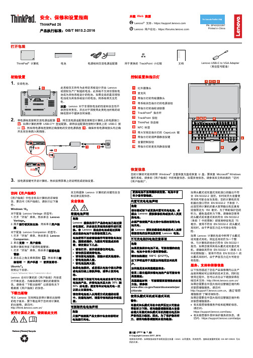
安全、保修和设置指南ThinkPad 25产品执行标准:GB/T 9813.2-2016关键 Web 资源® 支持:https:// 用户论坛:https://PN: SP40Q53397 Printed in China打开包装ThinkPad ® 计算机电池电源线和交流电源适配器用于更换的 TrackPoint 小红帽文档Lenovo USB-C to VGA Adapter(某些型号配备)初始设置 1. 安装电池。
此系统仅支持专为此特定系统设计并由 Lenovo 或授权生产厂制造的电池。
此系统不支持非授权电池或为其他系统设计的电池。
如果安装的是非授权电池或为其他系统设计的电池,则系统将无法充电。
注意:Lenovo 对于非授权电池的性能和安全性不承担任何责任,并且对于因使用此类电池所致的故障或损坏不提供任何保修。
2. 将电源线连接到交流电源适配器。
将交流电源适配器连接到您计算机上的电源接口。
如果计算机附带 USB-C TM 型适配器,请将该适配器连接到计算机上的 USB-C 接口 。
然后将电源线连接到正确接地的交流电源插座 。
确保所有电源线接头均正确并且完全地插入到插座。
3. 按电源按键可开启计算机。
然后按照屏幕上的说明完成初始设置。
控制装置和指示灯红外摄像头 麦克风带指示灯的传统摄像头 带系统状态指示灯的电源按钮 带指示灯的指纹读取器 TrackPoint ® 指点杆 TrackPoint 按钮 ThinkPad 轨迹板 NFC 标签带大写锁定指示灯的 CapsLock 键 带指示灯的扬声器静音按键 音量控制按钮带指示灯的麦克风静音按键恢复信息您的计算机可能未附带 Windows ® 全套恢复光盘或恢复 U 盘。
- 1、下载文档前请自行甄别文档内容的完整性,平台不提供额外的编辑、内容补充、找答案等附加服务。
- 2、"仅部分预览"的文档,不可在线预览部分如存在完整性等问题,可反馈申请退款(可完整预览的文档不适用该条件!)。
- 3、如文档侵犯您的权益,请联系客服反馈,我们会尽快为您处理(人工客服工作时间:9:00-18:30)。
GP2A25J0000F Series Detecting Distance : 1 to 9mm *OPIC Output,Refl ective Photointerrupter with Connector■DescriptionGP2A25J0000F Series are OPIC output, reflective photointerrupters with emitter and detector facing the same direction in a molding that provides non-contact sensing. This family of devices uses light modulation to reduce the affects of disturbing light, and the sensor is optimized to work in the selected focal distance. A 3-pin connector is included to allow remote-mount or off-board designs.■Features1. Refl ective with OPIC Light Modulated Output2. Highlights :• Includes additional screw fi xing holes• Position pin to prevent mis-alignment• Short focal distance3. Key Parameters:• Detecting distance : 1 to 9mm (White paper)3 to 7mm (Black paper)• Undetecting distance : over 27mm (White paper) • Connector : GP2A25J0000F ; Tyco Electronics AMP K.K.(PN : 292133-3)GP2A25DJ000F ; Tyco Electronics AMP K.K.(PN : 292133-3)GP2A25NJJ00F ; Tyco Electronics AMP K.K.(PN : 4-292133-3)4. Lead free and RoHS directive compliant ■Agency approvals/Compliance1. Compliant with RoHS directive■Applications1. General purpose detection of paper presence or mo-tion.2. Example : PPC, FAX, Printer* "OPIC"(Optical IC) is a trademark of the SHARP Corporation. An OPIC consists of a light-detecting element and a signal-processingNotice The content of data sheet is subject to change without prior notice.In the absence of confi rmation by device specifi cation sheets, SHARP takes no responsibility for any defects that may occur in equipment using any SHARP■Internal Connection Diagram■Outline Dimensions(Unit : mm)V CC V OUT GNDDate code (2 digit)1st digit2nd digit Year of production Month of production A.D.Mark Month Mark 2000011 2001122 2002233 2003344 2004455 2005566 2006677 2007788 2008899 2009910X 2010011Y ::12Zrepeats in a 10 year cycleCountry of originJapan■Absolute Maximum Ratings■Electro-optical Characteristics (T a=25˚C)Parameter Symbol Rating UnitSupply voltage V CC−0.5 to +7VOutput voltage V O30V*1 Output current I OL50mA*2 Operating temperature T opr−10 to +60˚C*2 Storage temperature T stg−20 to +80˚C∗1 Sink current refer to Fig.5.∗2 The connector should be plugged in/out at normal temperature.(T a=25˚C) Parameter Symbol Condhitions MIN.TYP.MAX.Unit Supply voltage V CC− 4.75− 5.25V Current dissipation (I)I CC Smoothing value V CC=5V, R L=∞−−30mA *3 Current dissipation (II)I CCP Pulse peak value V CC=5V−−150mA Low level output voltage V OL V CC=5V, I OL=16mA, at detecting time−−0.4V High level output voltage V OH V CC=5V, R L=1kΩ, at non detecting time 4.5−−V*4 Non detection distance L LHL KODAK Gray Cards, V CC=5V−−27mm*4 Detection distance L HLSKODAK Gray Cards, V CC=5V−−1mm Black paper, V CC=5V−−3L HLLKODAK Gray Cards, V CC=5V9−−mm Black paper, V CC=5V7−−*5 Response time t PLHV CC=5V−−1ms t PHL−−1ms*6 Acceptable illuminance Ev1−3 000−−lx Ev2 1 500−−lx∗3 Refer to Fig.1.∗4 Refer to Fig.2.∗5 Refer to Fig.3.*6 Refer to Fig.4.Refl ective object Black paper (black) : Standard refl ective object (provided by SHARP Corporation) KODAK Gray Cards (use the white side refl ects about 90%):Standardrefl ective object (provided by SHARP Corporation) PPC paper : Standard refl ective object (provided by SHARP Corporation)Fig.2 Test Condition for Detecting Distance CharacteristicsV OHV OLLHS LHLO u t p u t V ODetection surfaceFig.1 Test Condition for Peak Pulse Value I CCPV O GNDμs W sV CC =5V L =1k ΩFig.3 Test Circuit for Response TimeV O GNDV V CC =5V Reflective objectWithout reflective objectE V1 : At non-detectingE V2 : At detectingIlluminance shall be that on the emission/detection surface. Output shall not go from "H" to "L".Light source A PhotointerrupterFig.4 Test Condition for External Disturbing Light IlluminanceFig.5 Low Level Output Current vs. Ambient TemperatureFig.6 Low Level Output Voltage vs. Ambient Temperature6050403020100L o w l e v e l o u t p u t c u r r e n t I O L (m A )27Low level output current I OL (mA)L o w l e v e l o u t p u t v o l t a g e V O L (V )0.010.1Supply voltage V CC (V)Remarks : Please be aware that all data in the graph are just for reference and not for guarantee.■Design Considerations●Design guide1) V O terminal : Open collector outputThis product operates the light emitter by pulse drive. Please supply the stable supply voltage in order to prevent error operation by pulse current.Please use this device after connecting a capacitor between V O and GND for prevention of line noise.2) Prevention of detection errorPlease be careful that you need to keep the direct inverter light away from the photo detecting surface since the device will not operate correctly in such case.In addition, we recommend to make sure the operation test in the actual application.3) Plugging in/outThe connector should be plugged in/out at normal temperature.This product is not designed against irradiation and incorporates non-coherent IRED.●PartsThis product is assembled using the below parts.• Photodetector (Q'ty : 1) [Using a silicon photodiode as light detecting portion, and a bipolar IC as signal processing circuit]Category Maximum Sensitivitywavelength (nm)Sensitivitywavelength (nm)Response time (μs)Photo diode900700 to 1 200400• Photo emitter (Q'ty : 1)Category Material Maximum light emittingwavelength (nm)I/O Frequency (MHz)Infrared emitting diode(non-coherent)Gallium arsenide (GaAs)9500.3 • MaterialCase Lens Bottom cover GP2A25J0000FBlack polyphernylene Sulfi de resin (UL94 V-0)Acryl resin(UL94 HB)Polycarbonate resin (Black) (UL94 V-2)GP2A25DJ000J Polycarbonate resin (Black) (UL94 V-2) GP2A25NJJ00F∗Polycarbonate resin (Black) (UL94 V-2)∗The IR-90 fi lter (Fuji Photo Film Co., Ltd.) is inserted between case and detector side lens.• OthersLaser generator is not used.■Manufacturing Guidelines●Cleaning instructionsPolycarbonate resin is used as the material of the lens surface. So this product shall not be cleaned by cleaning solvent absolutely. Dust and stain shall clean by air blow, or shall clean by soft cloth.●Presence of ODCThis product shall not contain the following materials.And they are not used in the production process for this product.Regulation substances : CFCs, Halon, Carbon tetrachloride, 1.1.1-Trichloroethane (Methylchloroform)Specifi c brominated fl ame retardants such as the PBBOs and PBBs are not used in this product at all.This product shall not contain the following materials banned in the RoHS Directive (2002/95/EC).•Lead, Mercury, Cadmium, Hexavalent chromium, Polybrominated biphenyls (PBB), Polybrominateddiphenyl ethers (PBDE).■Package specifi cation●Case packagePackage materialsAnti-static plastic bag : PolyethtyleneMoltopren : UrethanePacking case : Corrugated fi berboardPackage method100 pcs of products shall be packaged in a plastic bag, Ends shall be sealed by stapler. The bottom ot the packing case is covered with moltopren, and 2 plastic bags shall be put int the packing case.Moltopren should be located after all product are settled (1 packing conteains 200 pcs).Packing composition■Important Notices· The circuit application examples in this publication are provided to explain representative applications of SHARP devices and are not intended to guarantee any circuit design or license any intellectual property rights. SHARP takes no responsibility for any problems related to any intellectual property right of a third party resulting from the use of SHARP's devices.· Contact SHARP in order to obtain the latest device specification sheets before using any SHARP device. SHARP reserves the right to make changes in the specifi cations, characteristics, data, materials, structure, and other contents described herein at any time without notice in order to improve design or reliability. Manufacturing locations are also subject to change without notice.· Observe the following points when using any devices in this publication. SHARP takes no responsibility for damage caused by improper use of the devices which does not meet the conditions and absolute maximum ratings to be used specifi ed in the relevant specifi cation sheet nor meet the following conditions:(i) The devices in this publication are designed for use in general electronic equipment designs such as:--- Personal computers--- Offi ce automation equipment--- Telecommunication equipment [terminal]--- Test and measurement equipment--- Industrial control--- Audio visual equipment--- Consumer electronics(ii) Measures such as fail-safe function and redundant design should be taken to ensure reliability and safety when SHARP devices are used for or in connection with equipment that requires higher reliability such as:--- Transportation control and safety equipment (i.e., aircraft, trains, automobiles, etc.)--- Traffi c signals--- Gas leakage sensor breakers--- Alarm equipment--- Various safety devices, etc.(iii) SHARP devices shall not be used for or in connection with equipment that requires an extremely high level of reliability and safety such as:--- Space applications--- Telecommunication equipment [trunk lines]--- Nuclear power control equipment--- Medical and other life support equipment (e.g., scuba).· If the SHARP devices listed in this publication fall within the scope of strategic products described in the Foreign Exchange and Foreign Trade Law of Japan, it is necessary to obtain approval to export such SHARP devices.· This publication is the proprietary product of SHARP and is copyrighted, with all rights reserved. Under the copyright laws, no part of this publication may be reproduced or transmitted in any form or by any means, electronic or mechanical, for any purpose, in whole or in part, without the express written permission of SHARP. Express written permission is also required before any use of this publication may be made by a third party.· Contact and consult with a SHARP representative if there are any questions about the contents of this publication.分销商库存信息:SHARP-MICROELECTRONICSGP2A25J0000F GP2A25NJJ00F。
