STR-D3012中文资料
CJT3012-1993井盖标准

铸铁检查井盖CJT3012-1993铸铁检查井盖CJT3012-1993中华人民共和国城镇建设行业标准CJ/T3012-93铸铁检查井盖Cast iron manhole top(节录)1、主题内容与适用范围 (1)2、引用标准 (1)3、术语 (1)4、产品瑾和标记示例 (2)5、承载等级 (2)6、技术要求 (3)7、试验装置及试验方法 (4)8、检验规则 (5)9、标志及证明书 (6)附加说明 (6)1、主题内容与适用范围本标准规定了铸铁检查井盖的承载等级、技术要求、试验方法、检验规则、标志。
2、引用标准GB 9439 灰铸铁件GB 1348 球墨铸铁件GB 6414-86 铸件尺寸公差3、术语3.1检查井通往地下设施(如自来水、排水、电信、电力、燃气、热力、消火栓、阀门、环境卫生等)的出入口。
3.2检查井盖检查井盖部的封闭物。
由支座和井盖组成。
3.2.1支座检查井盖中固定于检查井井口的部分。
用于安放井盖。
3.2.2井盖检查井盖中未固定部分。
其功能是封闭检查井口,需要时能够开启。
3.3嵌入深度支座支承面至支座顶面的高度。
3.4缝宽支座与井盖之间的间隙3.5支座支承面支承井盖的支座平面。
3.6井盖接触面井盖与支座支承面相接触的平面。
3.7检查井盖净宽D(mm)支座孔口的最大内切圆直径。
3.8试验荷载在测试检查井盖承载能力时规定施加的荷载。
4、产品型号和标记示例4.1铸铁检查井盖的编号由产品代号(JG),结构型式:单(D)、双层(S),主要参数:圆形井盖的公称直径(mm)或方形、矩形井盖的长(mm)×宽(mm),设计号四部分组成:4.2标记示例JG-D-6005、承载等级检查井盖按其承载能力不同分为重型与轻型两个等级(见表1)。
表 1等级标志设置场合重型重(Z)机动车行驶、停放的道路、场地轻型轻(Q)除上述范围以外的绿地,禁止机动车通行和停放的道路、场地6、技术要求6.1原材料6.1.1检查井盖可使用下述材料制作。
C-D开头集成电路

C-D开头的集成电路开头的集成电路CA 红外遥控电子选台集成电路C1490HA红外遥控信号接收集成电路C187 分配、十进制计数集成电路C301译码BCD-10段集成电路C68639Y 微处理集成电路C75P036 微处理集成电路CA0002 调幅模拟声解调集成电路CA2004 音频功率放大集成电路CA2006 音频功率放大集成电路CA270AW视频检波放大集成电路CA3075 调频中频放大集成电路CA3089 调频中频放大集成电路CA3120E视频信号处理集成电路CA3140 运算放大集成电路CA810 音频功率放大集成电路CA920 行扫描信号处理集成电路CAS126天线开关集成电路CAT24C16电可改写编程只读存储集成电路CAT35C104HP存储集成电路CC4000 或非门双3输入集成电路CC4008 计数4 位二进制集成电路CC40107与非双2输入缓冲、驱动集成电路CC40174六D触发集成电路CC40194移位寄存集成电路CC4025 或非门3输入集成电路CC4026 译码、驱动、十进制计数集成电路CC4027 上升沿J-K 触发集成电路CC4029 可预置4位可逆计数集成电路CC4033 译码、驱动、十进制计数集成电路CC4040 二进制计数、分频、振荡集成电路CC4047 单稳态触发集成电路CC4049 非门触发集成电路CC4051 模拟电子开关切换集成电路CC4053 电子开关切换集成电路CC4060 二进制计数、分频、振荡集成电路CC4067 模拟电子开关切换16选1集成电路CC4068 与非门8 输入集成电路CC4069 六非门集成电路CC4098 双单稳态触发集成电路CC4099 寄位锁存8 位集成电路CC4504 六非门集成电路CC4508 双四位锁存集成电路CC4518双BCD同步加法计数集成电路CC4520 双四位二进制同步加法计数集成电路CC4543锁存、译码、驱动BCD-7段集成电路CCST5007图文电视汉字存储集成电路CCU2OO0微处理集成电路CCU2O30微处理集成电路CCU-FBTV02微处理集成电路CCU-FDTV06微处理集成电路CD1130 调频/ 调谐及中频放大集成电路CD1140 调频/ 调谐及中频放大集成电路CD1452 双声道前置放大集成电路CD1514 音频功率放大集成电路CD1518 双声道音频功率放大集成电路CD2002 音频功率放大集成电路CD2611GS音频功率放大集成电路CD3161CS双声道前置放大集成电路CD3210 音频前置放大集成电路CD3220 音频前置放大集成电路CD4021BCM移位寄存并入、串出集成电路CD4160 单片录、放音集成电路CD4511 液晶显示驱动集成电路CD5132 图像中频放大、视频检波集成电路CD5435 行、场扫描信号处理集成电路CD5511 直流电机转速控制集成电路CD5522 电机稳速控制集成电路CD7243 伴音信号处理集成电路CD7366 发光二极管五位显示驱动集成电路CD74202CS音频功率放大集成电路CD74212CS音频功率放大集成电路CD7629 杜比降噪处理集成电路CD7630 双声道音调、音量、平衡控制集成电路CD7640CP调频/调幅中频放大集成电路CD7642 单片调幅收音集成电路CD7668AP双声道前置放大集成电路CD7784GP双声道前置放大集成电路CD810 场扫描输出集成电路CD8403CS场扫描输出集成电路CD9608CS双声道前置放大集成电路CDVS11C数据传输控制集成电路CF70200 字符信号处理集成电路CF723C6 制式切换集成电路CHC5CC2微处理集成电路CH2C8 数码显示驱动集成电路CH4C78 或非门集成电路CH5C81 主轴相位伺服控制集成电路CH52C1C荧光屏显控制集成电路CH52C11微处理集成电路CH52C12视频编码集成电路CH7001C视频编码集成电路CH7201 视频编码集成电路CHT0406微处理集成电路CHT0606微处理集成电路CHT0803微处理集成电路CHT0807微处理集成电路CHT0808微处理集成电路CHT0818微处理集成电路CIC1240A 电子振铃集成电路CIC9106 振铃集成电路CIC9145 音频、脉冲拨号集成电路CKP1001S微处理集成电路CKP1003S微处理集成电路CKP1004S微处理集成电路CKP1006S微处理集成电路CKP1008S微处理集成电路CKP1009S微处理集成电路CKP1101S微处理集成电路CKP1103S微处理集成电路CKP1105S微处理集成电路CKP1602S微处理集成电路CKP1603S微处理集成电路CL480 音频、视频解码集成电路CL482 音频、视频解码集成电路CL484 音频、视频解码集成电路CL680 音频、视频解码集成电路CL8820 音频、视频解码集成电路CL8830A 系统控制处理、编码、解码集成电路CM006CF数字会聚校正集成电路CM46745微处理集成电路CMS80D80解压集成电路CN9832 语言录、放音处理集成电路CNX82光电耦合集成电路CNY17-2 光电耦合集成电路CNY 71光电耦合集成电路CR3700 音频解码集成电路CRFU3-BF射频模块集成电路CS4338K音频数/模转换集成电路CS5339-KS 数/模转换集成电路CSC1032脉冲拨号集成电路CSC1062通话集成电路CSC2560缓冲拨号集成电路CSC91215A双音频、脉冲拨号集成电路CSC91215D双音频、脉冲拨号集成电路CSC91260双音频、脉冲拨号集成电路CSC95088双音频、脉冲拨号集成电路CT54136 异或门四2输入集电极开路输出集成电路CT54145译码、驱动BCD-10段集成电路CT54148 优先编码8-3 线集成电路CT54150 数据选择16-1 集成电路CT54154 多路解调4-16 集成电路CT54155 多路解调双2-4 集成电路CT54160同步可预置BCD计数集成电路CT54161同步可预置BCD计数集成电路CT54170寄存4X4集成电路CT54175双向正沿4D触发集成电路CT54181 算术逻辑单元集成电路CT54182 进位发生处理集成电路CT54192同步可逆递增、减BCD计数集成电路CT54193 可预置同步升、降二进制计数集成电路CT54198 双向移位寄存集成电路CT54251 数据选择8 输入集成电路CT54283 计数4位二进制集成电路CT5430 与非门8 输入集成电路CT5440 与非门双4 输入缓冲集成电路CT5442 译码4-10 线集成电路CT54H00与非门四2输入集成电路CT54H01与非门四2输入集成电路CT7420 与非门双4输入集成电路CTS774 微处理集成电路CTV222SPRC微处理集成电路CTV222SV1-3微处理集成电路CTV225SPRC微处理集成电路CTV322S微处理集成电路CTV360S微处理集成电路CVD-1 音频、视频解码集成电路CVPU2234梳状滤波视频信号处理集成电路CW117三端电源稳压0.5A集成电路CW117M E端电源稳压0.75A集成电路CW137L三端电源稳压0.5A集成电路CW317K三端电源稳压1.5A集成电路CW317L三端电源稳压0.1A集成电路CW337K三端电源负稳压集成电路CW723多端可调正稳压集成电路CX095C伴音信号处理集成电路CX099 本振与混频集成电路CX100D图像中频放大、视频放大集成电路CX108 色度、亮度信号处理集成电路CX109 色度信号处理集成电路CX1279S环绕声处理集成电路CX131 亮度信号调制集成电路CX134 磁头信号放大集成电路CX135 亮度信号处理集成电路CX136 色度信号处理集成电路CX158 行振荡集成电路CX177 图像中频放大、检波、视频放大集成电路CX187 亮度信号解调集成电路CX188 频率转换集成电路CX20014A图像、伴音中频放大集成电路CX20023 双声道记录、重放前置放大集成电路CX20029 调频/调幅收音集成电路CX20089A双声道音频功率放大集成电路CX20100 三基色接口集成电路CX20107 双声道音频功率放大集成电路CX20111 调频/调幅收音集成电路CX20125 黑电平扩展集成电路CX20155 电视调谐集成电路CX2016A红外遥控信号接收集成电路CX20172 双声道音频功率放大集成电路CX20197 射频放大集成电路CX22017 视频信号处理集成电路CX519-004P 微处理集成电路CX522-032 微处理集成电路CX522-054 微处理集成电路CX523-110P 微处理集成电路CX531-512P 微处理集成电路CX7925B调频/调幅电视锁相环频率合成集成电路CX7958 屏幕显示集成电路CX7959 存储集成电路CX857L 调频立体声解码集成电路CX864A视频信号调制、解调集成电路CX869B色度信号自动控制集成电路CXA1001AP色度、亮度信号处理集成电路CXA1005P双声道音频功率放大集成电路CXA1011M/P杜比降噪处理集成电路CXA1015M调幅收音集成电路CXA1017M调频收音集成电路CXA1019M调频/调幅收音集成电路CXA1030P调频/调幅收音集成电路CXA1033P调幅收音集成电路CXA1081M射频放大、伺服信号产生集成电路CXA1102杜比降噪处理集成电路CXA1110BS图像、伴音中频放大集成电路CXA1111调频/调幅收音集成电路CXA1114P开关切换集成电路CXA1145M双制式编码集成电路CXA1163M杜比降噪处理集成电路CXA1179AS选择控制集成电路CXA1191P调频/调幅收音集成电路CXA1213BS色度、亮度信号处理集成电路CXA1214P色度解码集成电路CXA1228S双制式解码集成电路CXA1229P双制式编码集成电路CXA1238M调频/调幅收音集成电路CXA1244S伺服控制集成电路CXA1249M数字环绕声处理集成电路CXA1262N单片录、放音集成电路CXA1278N单片录、放音集成电路CXA1279BS&频信号处理集成电路CXA1315M数/模转换集成电路CXA1315P辅助控制集成电路CXA1353画中画信号处理集成电路CXA1372S M频放大、伺服处理集成电路CXA1387S青晰度控制集成电路CXA1405AM键控指令比较集成电路CXA1420P亮度信号处理集成电路CXA1464AS色度、亮度及行场扫描信号处理集成电路CXA1526P字符地址、偏转及变换集成电路CXA1571S射频聚焦伺服信号处理集成电路CXA1587S色度、同步及行场扫描信号处理集成电路CXA1622音频功率放大集成电路CXA1644P回声效果发生集成电路CXA1645M E基色编码集成电路CXA1649M低音提升集成电路CXA1686M寸钟信号发生集成电路CXA1688M寸钟信号发生集成电路CXA1726AM动态会聚、聚焦信号控制集成电路CXA1735S环绕声处理集成电路CXA1779P基色信号处理集成电路CXA1782BD司服处理集成电路CXA1791M射频放大集成电路CXA1821射频放大集成电路CXA1855S视频信号选择集成电路CXA1875数/模转换集成电路CXA2016S同步信号识别集成电路CXA2021S音频信号处理集成电路CXA2050S视频信号处理、行场扫描信号处理集成电路CXA2055P视频前置放大集成电路CXA2066S视频前置放大集成电路CXA2067AS视频前置放大集成电路CXA2079Q切换TV/AV集成电路CXA2089Q视频切换集成电路CXA2093S清晰度控制集成电路CXA2130S色度、行场扫描信号处理集成电路CXA2549M司服处理集成电路CXA2555Q-T4射频放大集成电路CXA8008P单片放音集成电路CXA8020Q视频处理集成电路CXA8055M音频数/模转换集成电路CXD1053S画中画控制集成电路CXD1054S画中画控制集成电路CXD1135QZ^字信号处理集成电路CXD1167Q数字信号处理集成电路CXD1178Q数/模转换集成电路CXD1186CQ!可改写编程只读存储集成电路CXD1807Q视频解码集成电路CXD1850Q视频解码集成电路CXD1851C视频解码显示集成电路CXD1853G视频降噪集成电路CXD1865数字信号处理集成电路CXD1900A(视频解码集成电路CXD1904C解密集成电路CXD1914Q视频编码集成电路CXD2018Q场激励信号校正集成电路CXD25OOQ-140司服处理集成电路CXD2515数字信号、伺服信号处理集成电路CXD2517Q数字信号处理集成电路CXD2518Q司服驱动集成电路CXD2545Q数字信号处理集成电路CXD2560M数字滤波集成电路CXD2561BM数/模转换集成电路CXD2565AM数字滤波与数/模转换集成电路CXD2585Q数字、伺服信号处理集成电路CXD2586F数字、伺服信号处理集成电路CXD2741Q音频解码集成电路CXD8404Q数字时基校正集成电路CXD8505B徽字滤波集成电路CXD853Q ffl频降噪集成电路CXD8598R缓存集成电路CXD8599Q射频处理集成电路CXD8600R子画面图像集成电路CXD8602Q数据处理集成电路CXD8603R音频控制集成电路CXD8663数据处理集成电路CXD8664Q视频均衡处理集成电路CXD8669AQ军密集成电路CXD8696A-T2锁相环集成电路CXD8728QJ阵列集成电路CXD8730R数字信号处理集成电路CXD8747QJ阵列集成电路CXD8750N-T2数/模转换集成电路CXK1004L存储集成电路CXK1011P存储集成电路CXK1206MI视频信号存储集成电路CXK5864BSP静态随机存储集成电路CXL5005P延迟集成电路CXN82A光电耦合集成电路CXP1031Q系统控制集成电路CXP50116微处理集成电路CXP50116-409Q微处理集成电路CXP50116-702Q微处理集成电路CXP50116-713Q微处理集成电路CXP5058H系统控制处理集成电路CXP80420-139 微处理集成电路CXP80420-X133SP微处理集成电路CXP80424微处理集成电路CXP80424-146 微处理集成电路CXP80424-165S系统控制处理集成电路CXP82224-038Q系统控制处理集成电路CXP82224-044Q系统控制、显示驱动集成电路CXP82324-067Q系统控制处理集成电路CXP82612-007Q系统控制处理集成电路CXP84120微处理集成电路CXP84412微处理集成电路CXP85116B-636S微处理集成电路CXP85220A-047S系统控制处理集成电路CXP85220A-057S系统控制处理集成电路CXP85224A-037S系统控制处理集成电路CXP85332微处理集成电路CXP85332A-237S微处理集成电路CXP85340A微处理集成电路CXP853P40AQ-3微处理集成电路CXP85452-090S微处理集成电路CXP85460微处理集成电路CXP87852-061Q系统控制处理集成电路CY2292 时钟信号发生集成电路d开头的集成电路D1263C2双声道音频功率放大集成电路D1313HA音频前置放大集成电路D1362 音频前置放大集成电路D1470H 电机稳速控制集成电路D16F78B微处理集成电路D2010 磁头信号放大集成电路D2024 双声道音频功率放大集成电路D2283B 音频功率放大集成电路D260 调频/ 调幅收音集成电路D2822M双声道音频功率放大集成电路D3803 调频/ 调幅高、中频信号处理集成电路D3804 调频/ 调幅高、中频信号处理集成电路D4227ALE存储集成电路D5132 中频放大集成电路D54573 频段转换控制集成电路D5522 电机稳速控制集成电路D5622 色度解码集成电路D6121 红外遥控信号发射集成电路D6122G红外遥控信号发射集成电路D61245 红外遥控信号发射集成电路D6326C 微处理功能扩展集成电路D6336C 微处理功能扩展集成电路D6375A 数码录音电话处理集成电路D65640GD122门阵列集成电路D6600AA31红外遥控信号发射集成电路D7114 音频功率放大集成电路D7137 音频前置放大集成电路D7176AP伴音中频放大、鉴频及前置放大集成电路D7243P 音频信号处理集成电路D7315BP电子调谐频段转换集成电路D7325GS音频功率放大集成电路D7341GS自动选曲集成电路D7342P 调频立体声解码集成电路D7421 音频功率放大集成电路D7609AP行、场扫描信号处理集成电路D7628HP音频功率放大集成电路D7641 调幅收音集成电路D7666P 发光二极管五位显示驱动集成电路DBL2044 频段转换控制集成电路DF1700 数字滤波集成电路DM74LS164r移位寄存集成电路DMA2270视频、色度、亮度处理集成电路DMC73C167-003微处理集成电路DPU2553行、场扫描信号处理集成电路DSP56009音频解码集成电路DTI2222 数字瞬态改善集成电路DTI2251 数字瞬态改善集成电路DTI2260 数字瞬态改善集成电路DTVS888微处理集成电路DX0118CE桥式整流集成电路DY0689 电源厚膜集成电路。
KA3012D中文资料
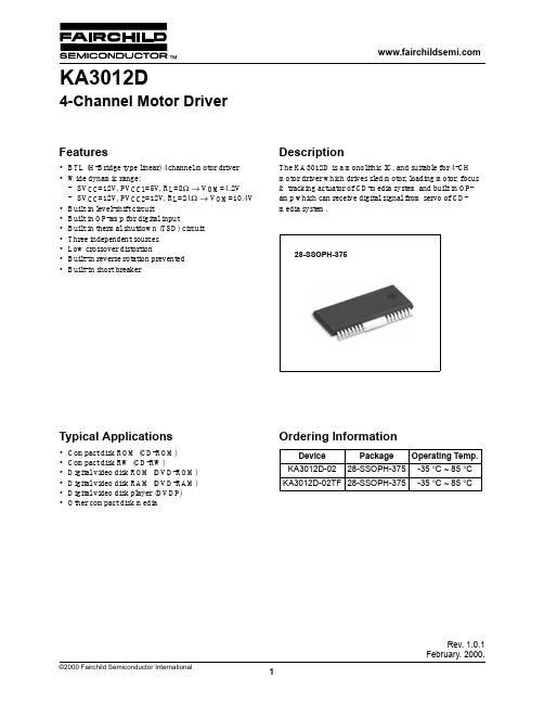
Rev. 1.0.1February. 2000.Features•BTL (H-Bridge type linear) 4channel motor driver •Wide dynamic range:-SV CC =12V , PV CC1=5V , R L =8Ω → V OM =4.2V -SV CC =12V , PV CC2=12V , R L =24Ω → V OM =10.4V •Built in level-shift circuit•Built in OP-amp for digital input•Built in thermal shutdown (TSD) circuit •Three independent sources •Low crossover distortion•Built-in reverse rotation prevented •Built-in short breakerDescriptionThe KA3012D is a monolithic IC, and suitable for 4-CH motor driver which drives sled motor, loading motor, focus & tracking actuator of CD-media system and built in OP-amp which can receive digital signal from servo of CD-media system.28-SSOPH-375Typical Applications•Compact disk ROM (CD-ROM)•Compact disk RW (CD-RW)•Digital video disk ROM (DVD-ROM)•Digital video disk RAM (DVD-RAM)•Digital video disk player (DVDP)•Other compact disk mediaOrdering InformationDevice Package Operating Temp.KA3012D-0228-SSOPH-375-35 °C ~ 85 °C KA3012D-02TF 28-SSOPH-375-35 °C ~ 85 °CKA3012D4-Channel Motor Driver元器件交易网KA3012DPin Assignments12345678910111213141516171819202122232425262728C H 1-O C H 1-O A M P 1-O A M P 1-I (−)A M P 1-I (+)B I A S S V C C G ND M U T EA M P 2-I (+)A M P 2-I (−)A M P 2-OC H 2-OC H 2-OG N DC H 4-OC H 4-OA M P 4-OA M P 4-I (−)A M P 4-I (+)P V C C 1P V C C 2A M P 3-I (+)A M P 3-I (−)C H 3-OC H 3-OG N DFIN (GND)FIN (GND)KA3012DA M P 3-O元器件交易网KA3012DPin DefinitionsPin Number Pin Name I/O Pin Function Description 1CH1-O O Drive CH 1 output (−)2CH1-O O Drive CH 1 output (+)3AMP1-O O Op-amp CH 1 output4AMP1-I(−)I Op-amp CH 1 input (−)5AMP1-I(+)I OP-amp CH 1 input (+)6BIAS I Bias input7SVCC-Supply voltage (Signal)8GND-Ground9MUTE I Mute10AMP2-I(+)I OP-amp CH 2 input (+)11AMP2-I(−)I Op-amp CH 2 input (−)12AMP2-O O Op-amp CH 2 output13AMP2-O O OP-amp CH 2 output (+)14CH2-O O Op-amp CH 2 output(Op-amp CH 2 output)15GND-Ground16CH3-O O Drive CH 3 output (−)17CH3-O O Drive CH 3 output (+)18AMP3-O O OP-amp CH 3 output19AMP3-I(−)I Drive CH 3 input (−)20AMP3-I(+)I Drive CH 3 input (+)21PVCC2-Supply voltage (CH 2 & CH 3)22PVCC1-Supply voltage (CH1 & CH 4)23AMP4-I(+)I OP-amp CH 4 input (+)24AMP4-I(−)I Op-amp CH 4 input (−)25AMP4-O O Op-amp CH 4 output26CH4-O O Drive CH 4 output (+)27CH4-O O Drive CH 4 output (−)28GND-GroundKA3012DInternal Block DiagramNOTE:The drive channel outputs are determined pre OP-amp output.1234567891011121314151617181920212223242526272810k10k 10k10k10k10k10k10k10k 10k 10k 10k10k10k10k 10k 10k20k10k20k 10k10k 10k 10kGNDPV CC1/2GND MUTETSDPV CC2/2PV CC2/2GNDSV CC PV CC1/2PV CC2/2PV CC2/2PV CC1/2+−+−−++−+−−+++−−+−LEVEL-SHIFT −+LEVEL-SHIFT −+−++−−++−LEVEL-SHIFT +−LEVEL-SHIFT −++−+−++−−PV CC2PV CC1C H 1-OC H 1-OA M P 1-OB I A SS V C CG N DM U T EA M P 2-I (+)A M P 2-I (−)A M P 2-OC H 2-OC H 2-OG N D C H 3-O C H 3-OA M P 3-OA M P 3-I (−)A M P 3-I (+)P V C C 1P V C C 2A M P 4-I (+)A M P 4-I (−)A M P 4-OC H 4-OC H 4-OG N DA M P 1-I (−)A M P 1-I (+)GNDGNDKA3012DEquivalent CircuitsOp-amp inputOp-amp outputDrive output BiasMuteAMP-I (−)AMP-I (+)4, 11, 19, 24Pin5, 10, 20, 23Pin80Ω80ΩAMP-O3, 12, 17, 25 Pin10k Ω10k Ω1k ΩCH-O(2, 13, 17, 26 Pin)CH-O(1, 14, 16, 27 Pin)200ΩBias (6 Pin)50k50kMute (9 Pin)KA3012DAbsolute Maximum Rating (Ta = 25°C)NOTE:1.When mounted on 50mm × 50mm × 1mm PCB (Phenolic resin material).2.Power dissipation reduces 13.6mW / °C for using above Ta=25°C.3.Do not exceed P D and SOA (Safe operating area).Power Dissipation CurveRecommended Operating Condition (Ta = 25°C)Parameter Symbol Value Unit Supply voltage V CC 15V Power dissipationP D 1.7note W Operating temperature range T OPR −35 ~ +85°C Storage temperature rangeT STG−55 ~ +150°CParameterSymbol Min.Typ.Max.Unit Supply voltageSV CC , V CC1, V CC24.5-13.2V3,0002,0001,0000255075100125150175Pd (mW)Ambient temperature, Ta [°C]SOA85KA3012DElectrical Characteristics(Ta=25°C, V CC1=V CC2=5V, R L=8Ω)Parameter Symbol Conditions Min.Typ.Max.Units DRIVE CIRCUITQuiescent current 1I CC1No load, Mute off-1520mA Quiescent current 2I CC2No load, Mute on--500uA Output offset voltage 1V OO1CH 1, CH 4−70070mA Output offset voltage 2V OO2CH 2, CH 3−90-90mV Max.output amplitude 1V OM1CH 1, CH 43 4.2-V Max.output amplitude 2V OM2CH 2, CH 3 (RL=24Ω)810.4-V1012.014dB Voltage gain 1G VC1V IN=0.1V RMS, 1kHz, sinewave.Input OP-amp→ Buffer CH 1, CH 4161820dB Voltage gain 2G VC2V IN=0.1V RMS, 1kHz, sinewave.Input OP-amp→ Buffer CH 2, CH 3Mute on voltage V Mon- 2.0--V Mute off voltage V Moff---0.5V INPUT OP-AMP CIRCUITInput offset voltage V OFOP-−10010mV Input bias current I BOP---300nA High level output voltage V OHOP-1010.9-V Low level output voltage V OLOP-- 1.1 1.8V1--mA Output driving current sink I SINK Input op-amp output→ V CC & 1.2kΩOutput driving current source I SOURCE Input op-amp output1--mA→ GND & 1.2kΩSlew rate SR100kHz square-wave 2Vp-p output-1-V / µsKA3012DApplication Information1. MUTE•When the voltage level of the mute pin is above 2V , the mute circuit is activated so that the output circuit will be muted.•When the mute pin #9 is open or the voltage of the mute pin #9 is below 0.5V , the mute circuit is deactivated and the output circuit operates normally.•When the mute circuit is activated, the voltage level of output pins becomes 1/2V CC (approximately).2. TSD (THERMAL SHUTDOWN)•If the chip temperature rises above 175°C, then the TSD (Thermal shutdown) circuit is activated and the output circuit is muted.•The V REF BG is the output voltage of the band-gap-referenced bias in circuit and acts as the input voltage of the TSD circuit.•The base-emitter voltage of the TR,Q11 is designed to turn-on at 460mA.V BE = V REF BG × R12 / (R11 + R12)=460mV•When the chip temperature rises up to 175°C, the turn-on voltage of the Q11 drops down to 460mV . (Hysteresis: 25°C) and Q11 turns on so the output circuit is muted.Pin #9Mute circuit High Turn-on Low Turn-off OpenTurn-off9Output driver biasV REF BGR11R12Q11Output driver biasKA3012D3. DRIVER•The gain of pre-op. Amplifier can be changed by manipulating amp input resistor or feedback resistor.•The voltage, V REF , is the reference voltage given by the bias voltage of the pin #6.•The level shift produces the current due to the difference between the pre amp output signal and the arbitrary reference (bias) signal. (The current produced as +∆I and −∆I is fed into the driver buffer. (CH1/CH4) The current produced as +2∆I and −2∆I is fed into the driver buffer. (CH2/CH3)•Driver buffer drives the power TR of the output stage according to the state of the input signal.•The output stage is the BTL driver and the motor is rotating in forward direction by operating TR Q1 and TR Q4.On the other hand, if TR Q2 and TR Q3 is operating, the motor is rotating in reverse direction.•When the output voltage of Pre-Amp (Pin 3, 12, 18, 25) is below the V REF , then the direction of the motor is in forward.•When the output voltage of Pre-Amp (Pin 3, 12, 18, 25) is above the V REF , then the direction of the motor in reverse.•The gain (A V ) of the drive circuit is as follows.4. CONNECT A BY-PASS CAPACITOR, 0.1µF BETWEEN THE SUPPLY VOLTAGE SOURCE.5. RADIATION FIN IS CONNECTING TO THE INTERNAL GND OF THE PACKAGE. CONNECT THE FIN TO THE EXTERNAL GND.+−+−+−10kBIAS (6 Pin)10kAMP−∆I+∆IBufferBufferQ1Q3MQ2Q4−∆V+∆VCH-O (1, 14,16, 27 Pin)CH-O (2, 13,17, 26 Pin)+−Level shiftAMP-I (+)(5, 10, 20, 23 Pin)AMP-I (−)(4, 11, 19, 24 Pin)AMP-O(3, 12, 18, 25 Pin)Pre-ampA V 20 log 4V INV IN ------------12dB () (CH1/CH4)==A V 20 log 4V INV IN------------18dB () (CH1/CH4)==7104V CC1KA3012D Typical Performance CharacteristicsV CC vs I CC (No load)VKA3012DTest CircuitsVVVAVVVVV12345678910111213141516171819202122232425262728KA3012DSW4R L410µFPV CC1O P O U TO P I N (+)O P I N (−)SW3O P I N (+)O P I N (−)O P O U TPV CC210µFR L3R L3’O P O U TO P I N (−)O P I N (+)O P O U TO P I N (−)O P I N (+)SW1R L1SV CC 10µFBias 2.5VV MUTESW2R L2R L2’12VOPIN (+)OPIN (−)OPOUTSW51231M ΩV IN1V IN21.2k ΩV CCSW7123SW6V IN3V IN510µF1M Ω231V IN4KA3012DTypical Application Circuits12345678910111213141516171819202122232425262728KA3012DFOCUS TRACKING BIAS SLEDLOADING (SPINDLE)MUTESERVO PREAMP MICOM10k Ω10k Ω10k Ω10k ΩMM10k Ω10k Ω10k Ω10k ΩBIASGNDGNDKA3012DLIFE SUPPORT POLICYFAIRCHILD’S PRODUCTS ARE NOT AUTHORIZED FOR USE AS CRITICAL COMPONENTS IN LIFE SUPPORT DEVICES OR SYSTEMS WITHOUT THE EXPRESS WRITTEN APPROVAL OF THE PRESIDENT OF FAIRCHILD SEMICONDUCTOR INTERNATIONAL. As used herein:1.Life support devices or systems are devices or systemswhich, (a) are intended for surgical implant into the body, or (b) support or sustain life, and (c) whose failure to perform when properly used in accordance with instructions for use provided in the labeling, can bereasonably expected to result in a significant injury of the user.2. A critical component in any component of a life supportdevice or system whose failure to perform can bereasonably expected to cause the failure of the life support device or system, or to affect its safety or effectiveness.DISCLAIMERFAIRCHILD SEMICONDUCTOR RESERVES THE RIGHT TO MAKE CHANGES WITHOUT FURTHER NOTICE TO ANY PRODUCTS HEREIN TO IMPROVE RELIABILITY, FUNCTION OR DESIGN. FAIRCHILD DOES NOT ASSUME ANYLIABILITY ARISING OUT OF THE APPLICATION OR USE OF ANY PRODUCT OR CIRCUIT DESCRIBED HEREIN; NEITHER DOES IT CONVEY ANY LICENSE UNDER ITS PATENT RIGHTS, NOR THE RIGHTS OF OTHERS.。
光盘驱动器
光盘驱动器在介绍光盘驱动器之前,有必要先了解一下光盘的概念。
光盘光盘作为软盘的替代者,不仅存储容量大、稳定性好,而且不易损坏,便于携带。
光盘可分为CD 、DVD 以及蓝光盘。
CD :在CD 格式中,人们熟悉的一个或许是音乐CD ,CD 英文全称为Compact Disc,它的直径是12cm ,是使用聚碳酸酯透明树脂制作的存储盘,盘面内部有很薄的铝板,数据就存储在这个地方。
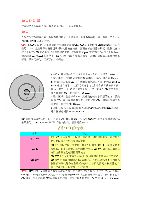
CD 的两面有很多螺旋型的细槽,这些槽叫做pit ,没有槽的平面部分叫做land ,数据通过pit 和land 重复存储,CD 可以分为存有数据的部分、开始记录数据的部分和结束部分,具体可分为如图所示的5个部分。
1中孔:用来固定盘面,以及用于旋转的孔,直径为15mm 。
2固定区域:用来固定中孔和数据区域的部分,直径为30mm 。
3:开始区域:记录CD 上存储的数据地址的区域,也叫做Lead-InArea 。
相当于音乐CD 上面记录音乐地址和各个曲目的演奏时间,相当于书的目录,若这个部分受损,不仅不能读入CD 中的数据,还不能识别CD ,直径为46~50 mm 。
4程序区域:若是音乐CD ,此处是存储音乐数据的地方,若是视频CD ,这里存储动态影像,若是程序CD ,则存储安装文件等数据,直径为50~116mm 。
5结束区域:实际数据的结束区域到CD 的边缘有0.5mm 的距离,这个区域也叫做Lead Out Area 。
CD 大致可以分为四种,出厂时就存储好数据的CD 、可以用CD-RW 驱动器等刻录设备记录数据的CD-R 、CD-RW 和可以存储电影等大量数据的DVD 。
各种CD 的特点 名称特点 工厂CD 工厂CD 是由基盘、反射层、保护层、和印刷层组成,通过激光束照射以后的反射光线读取数据。
CD-R CD-R 只可以存储一次数据,由4~5层组成。
CD-R 的最底层是聚碳酸脂,上面有凹槽。
这些凹槽会防止CD-RW 刻录机的激光头将发出的激光发射到错误的地方。
ZX-D32 单 BLE 蓝牙模块技术手册说明书
ZX-D32单BLE蓝牙模块技术手册版本:V1.6日期:2023/06/05目录1模块介绍 (2)1.1概述 (2)1.2特性 (3)1.3应用 (3)1.4基础参数表 (4)1.5工作电流参数表 (4)1.6出厂默认配置参数 (5)2应用接口 (6)2.1模块引脚定义 (6)2.2引脚功能表 (7)2.3特殊引脚IO功能表 (8)2.4电源设计 (8)2.5串口电平转换参考电路 (9)2.6应用原理图 (10)2.7应用原理图 (10)3回流焊曲线图 (11)4Layout注意事项 (11)5AT指令集 (13)6IO直驱模式 (16)6.1BLE通讯服务UUID说明(16位UUID) (16)6.2IO映射表 (16)6.3引脚功能定义 (17)6.4APP控制指令 (18)7更新记录 (23)8联系我们 (24)9免责申明和版权公告 (24)1.1概述ZX-D32是深圳市智兴微科技有限公司专为蓝牙无线数据传输打造的一款小尺寸蓝牙低功耗BLE模块,该模块为蓝牙5.0芯片,支持4.2BLE蓝牙协议,支持AT指令,用户可根据提供的AT指令自行更改串口波特率、设备名称等参数,也可以通过APP直接下发数据控制模块的IO口,操作灵活使用简单。
本模组具有极好的稳定性、超低成本以及超低的功耗和接收灵敏度高等优点,并且支持苹果、安卓APP 及微信小程序连接,可适配客户各种开发项目。
1.2特性●CPU:ARM968E-S●内存大小:160KB FLASH+20KB RAM ●蓝牙BLE5.0●功耗可低至0.5uA●工作频率:2.4GHZ●可视距离:80M●传输速率:250Kbps/1Mbps/2/Mbps ●发射功率:-20dBm~4dBm●接收灵敏度:-97dBm●支持UART,IIC,SPI,GPIO硬件接口●工作温度:-40℃~+85℃●天线采用PCB板载天线1.3应用●智能家居●定位追踪●智能教育设备●测量与监控系统●工业传感器与控制●医疗设备监测与无线控制1.4基础参数表参数名描述参数名描述型号ZX-D32模块尺寸13×26.7x1.5mm 蓝牙版本BLE5.0通信距离80M工作频段 2.402GHz-2.480GHz ISM band串口透传速率BLE4KB/S工作电压 1.8V~3.6V功能BLE透传、IO控制外设接口UART/SPI/I2C/ADC/GPIO天线板载天线调制方式GFSK工作温度-40℃~+85℃1.5工作电流参数表工作模式状态平均电流深度睡眠(无广播)无广播0.5uA广播状态(低功耗模式)100ms广播间隔290uA 200ms广播间隔150uA 500ms广播间隔68uA 1000ms广播间隔39uA广播状态(无低功耗模式)100ms广播间隔 1.78mA 连接状态BLE连接2mA1.6出厂默认配置参数功能出厂默认参数指令串口波特率9600AT+BAUD=3蓝牙名称D32LE_XXXXXX AT+NAME=D32LE_XXX XXX BLE服务UUID FFE0AT+SUUID=FFE0 BLE读写特征值UUID FFE1AT+CUUID=FFE12.1模块引脚定义2.2引脚功能表管脚名称类型功能1P00/TX I/O TXD/可编程输入输出引脚2P01/RX I/O RXD/可编程输入输出引脚3P31I/O编号E6,直驱模式输出口4P32I/O编号E7,直驱模式输出口5P35I/O编号E8,直驱模式输出口6P14I/O编号EC直驱模式PWM输出口7P17I/O编号E9,直驱模式输出口8P16I/O编号EA,直驱模式输出口9P34I/O编号EB,直驱模式输出口10P33I/O编号ED,直驱模式ADC输入口11RST I复位引脚(低电平有效)12VCC VCC电源(1.8-3.6V)13GND GND地14GND GND地15P13I/O功能输入按键引脚16P12I/O LED状态指示灯引脚17P11I/O蓝牙连接状态输出引脚18P10I/O低功耗模式引脚(未连接状态下有效) 19P07I/O编号E5,直驱模式普通输入口20P06I/O编号E4,直驱模式普通输入口21P05I/O编号E3,直驱模式普通输入口22P04I/O编号E2,直驱模式中断输入口23P03I/O编号E1,直驱模式中断输入口24P02I/O编号E0,直驱模式中断输入口25NC NC悬空2.3特殊引脚IO 功能表IO 脚功能描述P11蓝牙连接状态输出引脚:已连接(高电平)未连接(低电平)P13输入按键引脚:短按(断开蓝牙连接)长按3S(恢复出厂设置)P10输入引脚(未连接状态下有效):低电平:进入低功耗模式(串口指令失效、LED 灯不烁),功耗数据参见模块1.5章节电流数据高电平:高电平退出低功耗模式LED 状态指示灯(引脚P12高电平点亮)LED 显示连接状态匀速慢(500ms/on,500ms/off)未连接长亮已连接2.4电源设计ZX-D32的供电范围是1.8V ~3.6V ,推荐3.3V 的工作电压最佳。
STTH3012中文资料
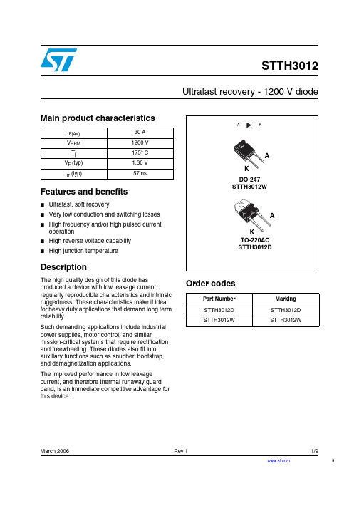
March 2006 Rev 11/99STTH3012Ultrafast recovery - 1200 V diodeMain product characteristicsFeatures and benefits■Ultrafast, soft recovery■Very low conduction and switching losses ■High frequency and/or high pulsed current operation■High reverse voltage capability ■High junction temperatureDescriptionThe high quality design of this diode has produced a device with low leakage current,regularly reproducible characteristics and intrinsic ruggedness. These characteristics make it ideal for heavy duty applications that demand long term reliability.Such demanding applications include industrial power supplies, motor control, and similarmission-critical systems that require rectification and freewheeling. These diodes also fit into auxiliary functions such as snubber, bootstrap, and demagnetization applications.The improved performance in low leakage current, and therefore thermal runaway guard band, is an immediate competitive advantage for this device.Order codesI F(AV)30 A V RRM 1200 V T j 175° C V F (typ) 1.30 V t rr (typ)57 nsPart Number Marking STTH3012D STTH3012D STTH3012WSTTH3012WCharacteristics STTH30122/91 CharacteristicsTo evaluate the conduction losses use the following equation: P = 1.60 x I F(AV) + 0.012 I F 2(RMS)Table 1.Absolute ratings (limiting values at 25° C, unless otherwise specified)Symbol ParameterValue Unit V RRM Repetitive peak reverse voltage 1200V I F(RMS)RMS forward current50A I F(AV)Average forward current, δ = 0.5T c = 105° C30A I FRM Repetitive peak forward currentt p = 5 µs, F = 5 kHz square300A I FSM Surge non repetitive forward current t p = 10 ms Sinusoidal 210A T stg Storage temperature range-65 to + 175°C T jMaximum operating junction temperature175°CTable 2.Thermal parametersSymbol ParameterValue Unit R th(j-c)Junction to case0.95°C/WTable 3.Static electrical characteristicsSymbol ParameterTest conditionsMin.TypMax.Unit I R (1)Reverse leakage currentT j = 25° C V R = V RRM20µAT j = 125° C 15150V F (2)Forward voltage dropT j = 25° C I F = 25 A2.1V T j = 125° C1.25 1.9T j = 150° C 1.201.8T j = 25° C I F = 30 A2.25T j = 125° C 1.35 2.05T j = 150° C1.301.951.Pulse test: t p = 5 ms, δ < 2 %2.Pulse test: t p = 380 µs, δ < 2 %STTH3012Characteristics3/9Table 4.Dynamic characteristicsSymbolParameterTest conditionsMin.TypMax.Unitt rrReverse recovery timeI F = 1 A, dI F /dt = -50 A/µs, V R = 30 V , T j = 25° C 115nsI F = 1 A, dI F /dt = -100 A/µs,V R = 30 V , T j = 25° C 5780I RM Reverse recovery current I F = 30 A, dI F /dt = -200 A/µs,V R = 600 V , T j = 125° C 2535A S Softness factor I F = 30 A, dI F /dt = -200 A/µs,V R = 600 V , T j = 125° C 1.5t fr Forward recovery time I F = 30 A dI F /dt = 100 A/µs V FR = 1.5 x V Fmax , T j = 25° C 550ns V FPForward recovery voltageI F = 30 A, dI F /dt = 100 A/µs,T j = 25° C6VFigure 1.Conduction losses versusFigure 2.Forward voltage drop versusCharacteristicsSTTH30124/9Figure 3.Relative variation of thermal impedance junction to caseFigure 4.Peak reverse recovery current versus dI F /dt (typical values)Figure 5.Reverse recovery time versusFigure 6.Reverse recovery charges versusFigure 7.Softness factor versus dI F /dt (typical values)Figure 8.Relative variations of dynamic parameters versus junctionSTTH3012Characteristics5/9Figure 9.Transient peak forward voltageFigure 10.Forward recovery time versus dI F /dtFigure 11.Junction capacitance versusreverse voltage applied (typicalPackage information STTH30126/92 Package informationEpoxy meets UL94, V0Cooling method: by conduction (C)Recommended torque value: 0.55 Nm (TO-220AC)Recommended torque value: 0.80 Nm (DO-247)Maximum torque value: 0.7 Nm (TO-220AC)Maximum torque value: 1.0 Nm (DO-247)STTH3012Package informationIn order to meet environmental requirements, ST offers these devices in ECOPACK®packages. These packages have a lead-free second level interconnect. The category ofsecond level interconnect is marked on the package and on the inner box label, incompliance with JEDEC Standard JESD97. The maximum ratings related to solderingconditions are also marked on the inner box label. ECOPACK is an ST trademark.ECOPACK specifications are available at: .7/9Ordering information STTH30128/93 Ordering information4 Revision historyPart Number Marking Package Weight Base qtyDelivery modeSTTH3012D STTH3012D TO-220AC 1.86 g50Tube STTH3012WSTTH3012WDO-2474.4 g30TubeDate RevisionDescription of Changes02-Mar-20061First issue.STTH3012Please Read Carefully:Information in this document is provided solely in connection with ST products. STMicroelectronics NV and its subsidiaries (“ST”) reserve the right to make changes, corrections, modifications or improvements, to this document, and the products and services described herein at anytime, without notice.All ST products are sold pursuant to ST’s terms and conditions of sale.Purchasers are solely responsible for the choice, selection and use of the ST products and services described herein, and ST assumes no liability whatsoever relating to the choice, selection or use of the ST products and services described herein.No license, express or implied, by estoppel or otherwise, to any intellectual property rights is granted under this document. If any part of this document refers to any third party products or services it shall not be deemed a license grant by ST for the use of such third party products or services, or any intellectual property contained therein or considered as a warranty covering the use in any manner whatsoever of such third party products or services or any intellectual property contained therein.UNLESS OTHERWISE SET FORTH IN ST’S TERMS AND CONDITIONS OF SALE ST DISCLAIMS ANY EXPRESS OR IMPLIED WARRANTY WITH RESPECT TO THE USE AND/OR SALE OF ST PRODUCTS INCLUDING WITHOUT LIMITATION IMPLIED WARRANTIES OF MERCHANTABILITY, FITNESS FOR A PARTICULAR PURPOSE (AND THEIR EQUIVALENTS UNDER THE LAWS OF ANY JURISDICTION), OR INFRINGEMENT OF ANY PATENT, COPYRIGHT OR OTHER INTELLECTUAL PROPERTY RIGHT. UNLESS EXPRESSLY APPROVED IN WRITING BY AN AUTHORIZE REPRESENTATIVE OF ST, ST PRODUCTS ARE NOT DESIGNED, AUTHORIZED OR WARRANTED FOR USE IN MILITARY, AIR CRAFT, SPACE, LIFE SAVING, OR LIFE SUSTAINING APPLICATIONS, NOR IN PRODUCTS OR SYSTEMS, WHERE FAILURE OR MALFUNCTION MAY RESULT IN PERSONAL INJURY, DEATH, ORSEVERE PROPERTY OR ENVIRONMENTAL DAMAGE.Resale of ST products with provisions different from the statements and/or technical features set forth in this document shall immediately void any warranty granted by ST for the ST product or service described herein and shall not create or extend in any manner whatsoever, anyliability of ST.ST and the ST logo are trademarks or registered trademarks of ST in various countries.Information in this document supersedes and replaces all information previously supplied.The ST logo is a registered trademark of STMicroelectronics. All other names are the property of their respective owners.© 2006 STMicroelectronics - All rights reservedSTMicroelectronics group of companiesAustralia - Belgium - Brazil - Canada - China - Czech Republic - Finland - France - Germany - Hong Kong - India - Israel - Italy - Japan - Malaysia - Malta - Morocco - Singapore - Spain - Sweden - Switzerland - United Kingdom - United States of America9/9。
D1D12资料
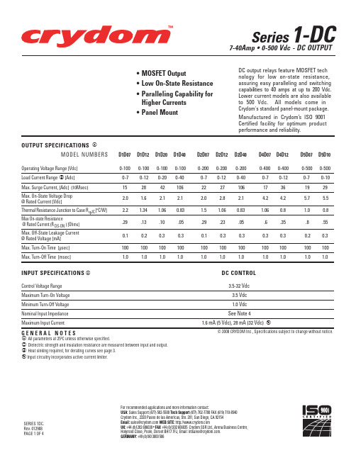
For recommended applications and more information contact: USA: Sales Support (877) 502-5500 Tech Support (877) 702-7700 FAX (619) 710-8540 Crydom Inc., 2320 Paseo de las Americas, Ste. 201, San Diego, CA 92154 Email: sales@ WEB SITE: UK: +44 (0)1202 606030 • FAX +44 (0)1202 606035 Crydom SSR Ltd., Arena Business Centre, Holyrood Close, Poole, Dorset BH17 7FJ, Email: intsales@. GERMANY: +49 (0)180 3000 506
2500 Vrms 10 9 Ohm
50 pF
Ambient Operating Temperature Range
-20 to 80ºC
Ambient Storage Temperature Range
-20 to 125ºC
MECHANICAL SPECIFICATIONS Weight: (typical)
© 2008 CRYDOM Inc., Specifications subject to change without notice.
For recommended applications and more information contact: USA: Sales Support (877) 502-5500 Tech Support (877) 702-7700 FAX (619) 710-8540 Crydom Inc., 2320 Paseo de las Americas, Ste. 201, San Diego, CA 92154 Email: sales@ WEB SITE: UK: +44 (0)1202 606030 • FAX +44 (0)1202 606035 Crydom SSR Ltd., Arena Business Centre, Holyrood Close, Poole, Dorset BH17 7FJ, Email: intsales@. GERMANY: +49 (0)180 3000 506
METTLER TOLEDO 腾达芯片科技 - 腾达芯片科技产品介绍说明书

METTLER TOLEDO is well established in the brewing industry, providing analytical inline instruments used by brewers around the world to help establish more cost-effective and reliable process automation. Previously our customers have been able to select systems for continuous measurement of dissolved oxygen, pH and conduc-tivity. However, we are pleased to announce the release of a new turbidity line with specific advantages for brewing – accompanied of course by the same high standard of application and service support that master brewers and quality assurance managers appreciate from a competent partner. What is turbidity?Turbidity is basically cloudiness in a liquid, which in wort or beer is caused by the presence of undissolved particles such as yeast, proteins or diatomaceous earth.These particles scatter the incident light and consequently lead to a milky or even opaque appearance of the liquid. The principle of light scattering is used in inline turbidimeters to measure the concentration of the undissolved particles:the higher the particle concentration the higher the scattered light intensity. The information on particle concentration is directly used to control individual process steps.What are the optical set-ups?Different particle concentration ranges require different optical set-ups for reliableTurbidity – new systemsfor brewing process optimization3and reproducible measurements. The measurement of forward and 90° scattered light has been proven to be the best optical method for turbidity in the range 0…100EBC (0…400 FTU). Higher particle concentrations – up to 250 g/l dry matter – are measured with backscattered light systems. The influence of different colored liquids on the intensity of the scattered light beams must be compensated by simultaneous measurement of a reference light beam or by the use of a light source emitting light in the near infrared range of the spectra. O ne of these techniques is always implemented in the turbidimeters described here.Trb 8300/InPro 8100 system still provides information for enhanced process control.In the filtration field, the most impor-tant applications are●control of centrifuges (similar to the measuring points in the brew house)●control of diatomaceous earth (Kieselgur) filtersEspecially in the last application, simultaneous measurement of forward and 90° scattered light provides important additional information on the type of par-ticle producing the turbidity. Typically, the 90° measurement value is between 0.3 and 2 EBC, representing turbidity caused by smaller particles such as proteins, which can be a key indicator for the shelf life of the final product. If this value is too high, the filter performance can be improved by changes in the Kieselgur dosage. Independent of this value, the for-ward scattered light signal should be smaller than the 90° signal. If this is not the case, then there are too many coarse particles in the beer. This is frequently an early warning sign of filter breakthrough,which could lead to very costly unsched-uled downtime.The recommended systems for the filtered beer measurement is ●a Trb 8300 F/S transmitter●an InPro 8500 dual-angle sensor (forward/90°)Similar to the InPro 8400 sensor line,InPro 8500 sensors are available in widely used line sizes, with different process con-nections and sapphire optics.What is your benefit?These new turbidity systems are complement-ary to the existing process analytical solu-tions from METTLER TOLEDO and help you to get the best out of your process.Brewery News 3METTLER TOLEDOBrewery News 3Turbidity – new systems for brewing process optimization New portable DO measurement system for control of your process quality INGOLD solutions –reliable quality helps to optimize productivity of brewing process Conductivity control in beer filler machinesMettler-Toledo GmbH Process Analytics Im Hackacker 15CH-8902 Urdorf Switzerland MarComCH-8902 Urdorf, Switzerland Mettler-Toledo GmbH ProzessanalytikD-35396 Gießen, Germany Archive MarComCH-8902 Urdorf, Switzerland andD-35396 Gießen, GermanySubject to technical changes. © Mettler-Toledo GmbH 01/04Printed in Switzerland.2What are the applications?In the brew house, the most important measurement points are after ●the lauter tun ●the whirlpool●hot wort centrifugesIn all three cases, inline turbidity measurement provides valuable informa-tion on the performance of the wort/solids separation process and allows immediate action to control the process. For example,after the lauter tun the switching point from lautering to wort pumping is opti-mized or the self-desludging mechanism of a centrifuge is controlled by the turbidity value in the clarified wort. The ideal meas-uring system consists of●a Trb 8300 F/S transmitter with high level operation●an InPro 8400 forward-scatter light sensor for direct pipe installation InPro 8400 flow-through sensors are available for the most common line sizes and process connections. The built-in sapphire optics easily withstand CIP solutions, minimizing the need for service and maintenance.In the fermentation sector, back-scattering systems provide important information on the cell growth of yeast in fermenters – the higher the cell concen-tration, the higher the light scattered back from the yeast cells. A typical measurement system consists of●a Trb 8300 transmitter with application-specific calibration routines●an InPro 8100 probe for direct installa-tion in a fermenter●an InFit 761 CIP housingDue to the backscattered light princi-ple and the use of fiber optic technology,the system shows a much wider linear measuring range than do competing absorption measurement systems. Even at extremely high yeast concentrations,where absorption systems have long reached their saturation limit, theIn Pro 8500.Typical METTLER TOLEDOINGOLDmodular sensor design.Brewery News 3METTLER TOLEDO3New portable DO measurement system for control of your process quality!InTap 4004 e.Time saving, easy handling and user-friendlyINGOLD InTap 4000e or InTap 4004e DO analyzers can easily be connected to your process. Both analyzers have an intu-itive control menu, resulting in maximum convenience for users during calibration,measurement and maintenance proce-dures.Cost-savingInTap 4000e and InTap 4004e offer our best price /performance ratio ever. The sensor maintenance cycle takes just two minutes, thereby minimizing operating expense. And, the analyzers are now powered by three standard, user-replace-able, batteries.Long lifetimeThe watertight measuring unit and the impact-resistant protective casing provide assurance for reliable DO measurements,even under the harshest operating condi-tions encountered in the beverage industry.Precise and fast measurements The optimized measuring chamber and advanced sensor design guarantee fast, sta-ble and repeatable results, unaffected by flow rate or very low DO concentration.In the beverage industry, dissolved oxygen (DO) concentration is one of the most important process parameters for controlling the quality of the final product. The InTap 4000e /4004e allow users to perform DO measure-ments wherever and whenever required. Typical applications are product quality control or leak detection in process plant equipment. The InTap 4000 e and 4004 e were designed and engineered for maximum operational efficiency, ease-of-handling, reliability, and the highest possible security. A convincing concept in any case –regardless of how you measure dissolved oxygen in your plant, either with or without Zwickel connection hardware.Two-minute-maintenanceThe modular METTLER T O LED O INGO LD sensor design allows easy and rapid maintenance to save you time.Fast response time and low detec-tion limitTime savings through fast-response measurement of oxygen concentration.Fast tank-to-tank equilibration even at val-ues below 10ppb.Data managementInTap 4000e /4004e can store up to 200 measurement values. The accompany-ing Paraly ®software allows data transfer to a PC for further processing using stan-dard spread sheet programs.pH measurementA complete range of hygienic and CIP suitable pH electrodes are available with low drift and long service life, including gel-elec-trolyte, temperature compensated pH electrodesThe InPro 3200 makes high-accuracy performance possible under low pressure due to a partly flowing reference junction.Conversely, the InPro 3100 is purposely designed for high pressure applications.“Advanced Line” pH transmitter The pH 2100 e offers high quality performance with an easy-to-use interface,diagnostic information, two current outputs and integrated PID controller. Two wire units are available with HART ®or PROFIBUS ®interfaces.Brewery News 3METTLER TOLEDO4INGOLD solutions – reliable quality helps to optimize productivityThe most critical point for pH control throughout the brewing process is certainly during mashing because of the resulting impact upon the subsequent wort and beer processes. Control of dissolved oxygen is just as crucial because it is a fundamental indicator for taste, shelf life and clarity. Oxygen uptake at the lauter tun already has a direct influence on turbidity and color as well as on quality of bitterness. INGOLD DO, pH and newly introduced turbidity measurement systems ensure optimal inline process control and help you produce the highest quality beer possible.Comprehensive range of sterilizaThe retractable housing family InTrac 797 e and InTrac 799 e are opti-mally suited for sterilization of pH electrodes as well as for DO and turbidity sensors. InTrac 798 offers enhanced safety and improved cleanability (with EHEDG certified process connections).EasyClean – the automated pH measurementIn applications with frequent calibra-tion requirements automated cleaning and calibration systems help ensure reliable measurements, longer sensor life time and a resulting lower cost of operation.Turbidity measurementWort quality control with turbidity The forward/side scatter turbidity sen-sors InPro8400/8500 are calibrated in EBC turbidity units and are directly inserted in-to pipes. The flow-through sensors are CIP suitable and available with a variety of process connections and pipe sizes.The turbidity transmitter Trb8300 F/S offers high user convenience through plain text menus. The built-in ProCal®calibra-tion routine allows an easy adaptation of turbidity values to laboratory results. Enhanced performanceThe 024100 e is an advanced per-formance transmitter with a unique sample calibration routine that assures highly accurate measurements, particular-ly in continuous processes. The standard version features two current outputs and a PID controller. A PRO FIBUS®version offers remote communication and diag-nostics.Brewery News3METTLER TOLEDO 5ble retractable housings Dissolved oxygen measurementUnmatched hygienic designThe well proven DO sensor InPro6800 offers a reliable and accurate measure-ment in a variety of brewhouse applica-tions in mashing, lautering and wort processes. Now in the third product gener-ation our sensor complies with EHEDG and 3-A standards and comes with 3.1B material certificates. The service-friendly design of the inner body guarantees optimal cost-of-ownership.Approved hygienic design allows:●Safe insertion and withdrawal of sensors ●Sensor and electrode exchange during ongoing process.For standard applications METTLER TO LEDO offers an optimal and flexible solution with the well proven InTrac777 e.ProcessIn the final process of beer production,beer is filled into bottles or cans. In the filler machine, an amount of beer stored in a tank is filled into the bottles by applying differential pressure through CO 2injec-tion.In this process beer is filled into the bottle by applying CO 2 with a pressure of 0to 6 bar. During the CIP (Cleaning-in-Place) process, cleaning solution and wa-ter is circulating both in the machine and in the pipes that bring beer from the pro-duction to the packaging area.By the time the final wash-cycle of the CIP has ended, the pipes and filling machine are completely filled with water.When production is resumed, the actual filling process usually commences only after a specified time delay (drainage), and the first bottles then have to go through a lab analysis to determinate which bottlesBrewery News 3METTLER TOLEDOstart for the filling process, results in a ful-ly automated process with minimal loss of bottles and beer, as well as reduces labor costs.The METTLER TOLEDO solution METTLER TO LEDO offers a series of reliable sensors with a variety of process connections for this application. The system used is a Cond 7100 e, with an InPro 7002 series sensor, the sensor being installed in the pipe that feeds beer to the filler machine.6Conductivity control in beer filler machinesTransmitter Cond 7100 e.have to be rejected and which have the correct concentration of beer (no water contamination) to go to the market.If the waiting time is set too short, this results in a loss of bottles/cans. If the time is set too long, good beer will be sent down the drain. In addition, an operator is tied to the drain trying to visually determine by color the exact moment when water ends and beer starts.Typical process conditions:●Media: water, beer ●Pressure: up to 6 bar●Temperature: -2...25 °C, 28...77 °F ●Conductivity range: beer approx. 1500µS/cm, water approx. 100...150 µS/cm The use of a conductivity system to control the exact phase separation between water and beer ensure the correctParticularly useful in the Food &Beverage industry, conductivity is an ideal way to control the separation of two liquids with different conductivity values. One example is the measurement of conductivity of beer and water in the beer filler machine. By using a conductivity measuring sys-tem, the process is easily automated. Less reliable manual media separation based on visual surveillance through a sight glass becomes obsolete. This results in minimization of media loss, reduced labor cost and increased process safety and reliability.InPro 7002-VP .Precise phase detectionThe InPro7002-VP conductivity sensor is used to detect the exact switch-over from one phase to the other. This is registered very rapidly and precisely due to the fast response time for both conductivity and temperature measurements, combined with a factory-determined cell constant.Instantaneous response2-electrode conductivity systems have a response time of about one second. The distance between the sensor and the (filler)valve should be used in the calculation for setting the timing, provided installation possibilities allow for it. The sensor must be installed upstream from the valve.Minimization of media lossWith fast and precise phase detection,the loss of product in the installation can be remarkably minimized.7Brewery News 3METTLER TOLEDOCertified quality and materialsAccurate measurements are only possible if the cell constant has been de-termined accurately. 2-electrode sensors from METTLER TO LEDO are delivered with a certified and documented NIST/ASTM- traceable cell constant, en-suring the highest degree of accuracy. All materials in contact with the media are FDA compliant MaxCert TM , a package of certificates, supports the validation and qualification process.InstrumentationAs far as the transmitter is concerned,the Cond 7100 e series is the best choice for simple operation, precise and reliable measurements as well as low cost of ownership. The dual current outputs not only monitor the conductivity value but also temperature. The use of two com-pletely independent parameter sets allows/conductivitythe system to control phase detection very precisely, even if the conductivity change spans several orders of magnitude. With its unique user interface (pictographs) and continuous instrument and sensor diagnostics, this transmitter can be employed in all relevant process applications.tries, using tested and EHEDG-certified process connectors such as Tuchenhag-en Varivent, Neumo-BioControl, Tri-Clamp, and Ingold cap nut.●safe steam sterilization of the sensor in the flushing chamber●process connector and flushing chamber formed from a single piece of stainless steeel●complete absence of crevices or slits ●full hygienic cleaningThis completely new housing raises the bar for sanitary design. The InTrac 798 is cer-tified in accordance with EHEDG and 3-A guidelines. It is equipped with a state-of-the-art flushing chamber designed to opti-mize cleanability. The unit is outstanding for its array of advanced features such as:●totally drainable flushing chamber due to the positioning of the O-ring●use of 12 mm sensors of uniform length (120 mm)●suitability for applications in the food processing and pharmaceutical indus-With the InTrac798, METTLER TOLEDO INGOLD offers a retractable housing specifically designed for the pharmaceutical and food industries. Increasing demands for hygienic equipment design and the need to access the sensor at any time, have led to the development of this advanced housing model.InTrac 798 –for the most demanding hygienic requirements● standard use of FDA-compliant EPDMfor all wetted O-rings (other materials on request)The hygienic process connection (flange)and drainable flushing chamber are in-geniously combined into one single ele-ment, making this retractable housing a real innovation in its field.InTrac 798.INGOLDLeading Process AnalyticsMettler-Toledo GmbH Process Analytics Im Hackacker 15CH-8902 Urdorf /housings。
DW01 中文技术资料

DW01A (文件编号:S&CIC0822)锂电池保护电路一、描述DW01A是一个锂电池保护电路,为避免锂电池因过充电、过放电、电流过大导致电池寿命缩短或电池被损坏而设计的。
它具有高精确度的电压检测与时间延迟电路。
二、主要特点工作电流低;过充检测4.3V,过充释放4.1V;过放检测2.4V,过放释放3.0V;过流检测0.15V,短路电流检测1.0V;充电器检测;过电流保护复位电阻;带自恢复功能工作电压范围广;小封装。
三、应用单一锂电池保护电路。
DW01A (文件编号:S&CIC0822)锂电池保护电路五、极限参数六、电气特性参数(除非特别指定,Tamb=25℃)过充电状态当从正常状态进入充电状态时,可以通过VDD检测到电池电压。
当电池电压进入到这充电状态时,VDD 电压大于VOC P,迟延时间超过TOC,M2关闭。
释放过充电状态进入过充电状态后,要解除过充电状态,进入正常状态,有两种方法。
●如果电池自我放电,并且VDD<VOCR,M2开启,返回到正常状态。
●在移去充电器,连接负载后,如果VDD<VOCP,M2开启,返回到正常模式。
过放电检测当由正常状态进入放电状态时,可以通过VDD检测到电池电压。
当电池电压进入过放电状态时,VDD电压小于VOD P,迟延时间超过TOD,则M1关闭。
释放过放电模式如果在过放电模式有一个充电器连接电池,电压将变为VCSI<VC HA和VDD>VODR,M1开启并返回到常模式;或者当负载悬空,VDD电压恢复到VDD>VODR,M1开启并返回到正常模式(自恢复功能)。
充电检测当一个充电器连接电池,电压将变为VCSI<VCHA,这样IC检测到充电器已接入。
过电流/短路电流检测在正常模式下,当放电电流太大时,由CSI管脚检测到电压大于VOIX(V OI1或V OI2),并且迟延大于TOIX(T OI1或T OI2),则代表过电流(短路)状态。
MUR30120PT中文资料
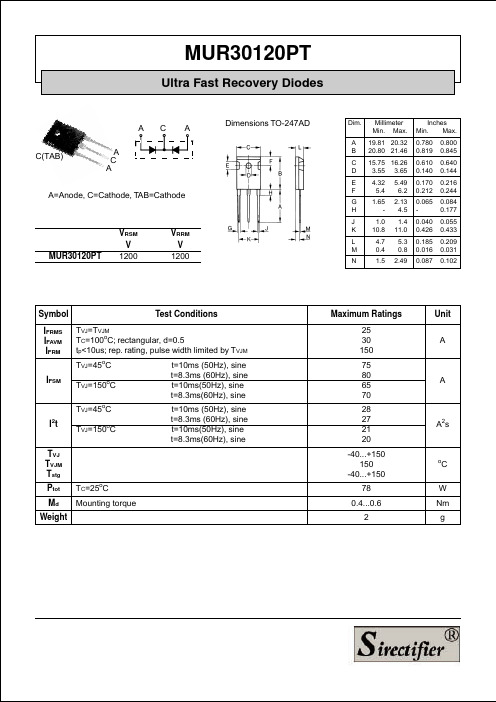
Inches Min. Max. 0.780 0.819 0.610 0.140 0.170 0.212 0.065 0.040 0.426 0.185 0.016 0.087 0.800 0.845 0.640 0.144 0.216 0.244 0.084 0.177 0.055 0.433 0.209 0.031 0.102
A=Anode, C=Cathode, TAB=Cathode
MUR30120PT
VRSM V 1200
VRRM V 1200
J K L M N
Symbol IFRMS IFAVM IFRM
Test Conditions TVJ=TVJM TC=100oC; rectangular, d=0.5 tp<10us; rep. rating, pulse width limited by TVJM TVJ=45oC t=10ms (50Hz), sine t=8.3ms (60Hz), sine t=10ms(50Hz), sine t=8.3ms(60Hz), sine t=10ms (50Hz), sine t=8.3ms (60Hz), sine t=10ms(50Hz), sine t=8.3ms(60Hz), sine
30
TVJ=100°C A V =540V R 25 max. 20 15 10 5 0 0 100 200
-diF/dt
IF
Qr
IF=11A IF=22A IF=11A IF=5.5A
IF=11A IF=22A IF=11A IF=5.5A
typ.
300 A/µs
400
Fig. 1 Forward current versus voltage drop.
STPR320D中文资料

STPR310D/F STPR320D/FFebruary 1992Ed:1ULTRA FAST RECOVERY RECTIFIER DIODESLow cost single chip rectifier suited for switchmode power supply and high frequency DC to DC conver-ters.Packaged in TO220AC and ISOWATT220AC,this device is intended for use in low voltage,high fre-quency inverters,free wheeling and polarity protec-tion applications.ABSOLUTE RATINGS (limiting values)THERMAL RESISTANCEDESCRIPTIONSymbol ParameterValue Unit I F(RMS)RMS Forward Current 10A I F(AV)Average Forward Current δ =0.5TO220ACTc =125°C3AISOWATT220AC Tc =120°CI FSM Surge Non Repetitive Forward Current Tp =10ms Sinusoidal30A Tstg Tj Storage and Junction Temperature Range-65to +150-65to +150°CSymbolParameter STPR Unit310D 310F320D 320F V RRMRepetitive Peak Reverse Voltage100200V Symbol ParameterValue Unit Rth (j-c)Junction-caseTO220AC 6.5°C/WISOWATT220AC8.5.SUITED FOR SMPS .LOW LOSSES.LOW FORWARD AND REVERSE RECOVERY TIME.HIGH SURGE CURRENT CAPABILITY .HIGH AVALAN CHE ENERGY CAPABILITYSTPR310D STPR320DSTPR310F STPR320FTO220AC (Plastic)ISOWATT220AC(Plastic)KA KA1/6ELECTRICAL CHARACTERISTICS STATIC CHARACTERISTICSSymbol Tests Conditions Min.Typ.Max.Unit I R *Tj =25°C V R =V RRM50µA Tj =100°C0.5mA V F **Tj =125°C I F =3A 0.99VTj =125°C I F =6A 1.20Tj =25°CI F =6A1.25To evaluate the conduction losses use the followin g equation :P =0.78x I F(AV)+0.070I F 2(RMS)Symbol Tests Conditions Min.Typ.Max.Unit trr Tj =25°C I F =0.5A I R =1A Irr =0.25A 30ns tfr Tj =25°C I F =1A tr =10ns V FR =1.1x V F20ns V FPTj =25°CI F =1Atr =10ns3VRECOVERY CHARACTERISTICSPulse test :*tp =5ms,duty cycle <2%**tp =380µs,duty cycle <2%Fig.2:Peak current versus form factor.Fig.1:Average forward power dissipation versus aver-age forward current.STPR310D/F /STPR320D/F2/6Fig.3:Average current versus ambient temperature. (duty cycle:0.5)(TO220AC)Fig.5:Non repetitive surge peak forward current versus overload duration.(Maximum values)(TO220AC)Fig.6:Non repetitive surge peak forward current versus overload duration.(Maximum values)(ISOWATT220AC)Fig.4:Average current versus ambient temperature. (duty cycle:0.5)(ISOWATT220AC)Fig.8:Relative variation of thermal transient impedance junction to case versus pulse duration.(ISOWATT220AC)Fig.7:Relative variation of thermal transient impedancejunction to case versus pulse duration.(TO220AC)STPR310D/F/STPR320D/F3/6Fig.9:Forward voltage drop versus forward current. (Maximum values)Fig.10:Junction capacitance versus reverse voltage applied.(Typical values)Fig.11:Recovery charge versus dIF/dt.Fig.12:Peak reverse current versus dIF/dt. Fig.13:Dynamic parameters versus junction tempera-ture.STPR310D/F/STPR320D/F4/6Cooling method :CMarking :Type number Weight :2gRecommended torque value :0.55m.N Maximum torque value :0.70m.N Electrical Isolation :2000V DC Capacitance :12pFPACKAGE MECHANICAL DATA TO220AC (JEDEC outline)Cooling method :CMarking :Type number Weight :1.9gRecommended torque value :0.55m.N Maximum torque value :0.7m.N PACKAGE MECHANICAL DATA ISOWATT220AC (JEDEC outline)AGDEBCI PONJHKLMFREF.DIMENSIONSMillimeters Inches Min.Max.Min.Max.A 1010.40.3930.409B 15.215.90.5980.626C 13140.5110.551D 6.2 6.6 0.2440.260E 16.4typ.0.645typ.F 3.5 4.20.1370.165G 2.65 2.950.1040.116H 4.4 4.60.1730.181I 3.75 3.850.1470.151J 1.23 1.320.0480.051K 1.27typ.0.050typ.L 0.490.700.0190.027M 2.4 2.720.0940.107N 4.95 5.150.1940.203O 1.14 1.700.0440.067P0.610.880.0240.034ABCIDOPNMLEJHREF.DIMENSIONSMillimeters Inches Min.Max.Min.Max.A 1010.40.3930.409B 15.916.40.6260.645C 28.630.61.126 1.204D 16typ 0.630typ E 99.30.3540.366H 4.4 4.60.1730.181I 3 3.20.1180.126J2.5 2.70.0980.106L 0.40.70.0150.027M 2.4 2.750.0940.108N 4.95 5.20.1950.204O 1.15 1.70.0450.067P0.7510.0300.039STPR310D/F /STPR320D/F5/6STPR310D/F/STPR320D/FInformation furnished is believed to be accurate and reliable.However,SGS-THOMSON Microelectronics assumes no responsability for the consequences of use of such information nor for any infringement of patents or other rights of third parties which may results from its use.No license is granted by implication or otherwise under any patent or patent rights of SGS-THOMSON Microelectronics.Specifications mentioned in this publication are subject to change without notice.This publication supersedes and replaces all information previously supplied.SGS-THOMSON Microelectronicsproducts are not authorized for use as critical components in life support devices or systems without express written approval of SGS-THOMSON Microelectonics.©1994SGS-THOMSON Microelectronics-All Rights ReservedTURBOSWITCH,TRANSIL,TRISIL,SNUBBERLESS are Trademarks of SGS-THOMSON Microelectronics.SGS-THOMSON Microelectronics GROUP OF COMPANIESAustralia-Brazil-France-Germany-Hong Kong-Italy-Japan-Korea-Malaysia-Malta-Morocco-The Netherlands-Singapore-Spain-Sweden-Switzerland-Taiwan-Thailand-United Kingdom-U.S.A6/6。
EG3012芯片数据手册说明书

版本变更记录目录1. 特点 (4)2. 描述 (4)3. 应用领域 (4)4. 引脚 (4)4.1. 引脚定义 (4)4.2. 引脚描述 (4)5. 结构框图 (5)6. 典型应用电路 (5)7. 电气特性 (7)7.1 极限参数 (7)7.2 典型参数 (8)7.3 开关时间特性及死区时间波形图 (9)8. 应用设计 (10)8.1Vcc端电源电压 (10)8.2输入逻辑信号要求和输出驱动器特性 (10)8.3自举电路 (11)9. 封装尺寸 (12)9.1 SO8封装尺寸 (12)EG3012芯片数据手册V1.01. 特点⏹高端悬浮自举电源设计,耐压可达100V⏹内建死区控制电路⏹电源电压欠压关断输出⏹自带闭锁功能,彻底杜绝上、下管输出同时导通⏹采用半桥达林顿管输出结构具有大电流栅极驱动能力⏹专用于无刷电机N沟道MOS管、IGBT管栅极驱动⏹HIN输入通道高电平有效,控制高端HO输出⏹LIN输入通道高电平有效,控制低端LO输出⏹外围器件少⏹静态电流小:4.5mA⏹封装形式:SOP-82. 描述EG3012是一款高性价比的大功率MOS管、IGBT管栅极驱动专用芯片,内部集成了逻辑信号输入处理电路、死区时控制电路、欠压关断电路、闭锁电路、电平位移电路、脉冲滤波电路及输出驱动电路,专用于无刷电机控制器中的驱动电路。
EG3012高端的工作电压可达100V,Vcc的电源电压范围宽11V~30V,静态功耗低仅4.5mA。
该芯片具有闭锁功能防止输出功率管同时导通,输入通道H IN和L IN内建了一个10K下拉电阻,在输入悬空时使上、下功率MOS管处于关闭状态,输出结构采用半桥式达林顿管结构,采用SOP8封装。
3. 应用领域⏹电动摩托车控制器⏹电动自行车控制器⏹100V降压型开关电源⏹变频水泵控制器⏹无刷电机驱动器⏹高压Class-D类功放4. 引脚4.1. 引脚定义IN IN图4-1. EG3012管脚定义4.2. 引脚描述5. 结构框图H LOGNDVccHOVS VBL图5-1. EG3012结构框图6. 典型应用电路+15V+VinH L OUT图6-1. EG3012典型应用电路图——中、小功率半桥驱动应用EG3012芯片数据手册V1.0+15V+VinH L OUT图6-2. EG3012典型应用电路图——大功率电机场合应用+15V+VinH L OUT图6-3. EG3012典型应用电路图——外接自举二极管应用大功率MOS 管、IGBT 管栅极驱动芯片EG3012芯片数据手册V1.0大功率MOS管、IGBT管栅极驱动芯片7. 电气特性7.1 极限参数注:超出所列的极限参数可能导致芯片内部永久性损坏,在极限的条件长时间运行会影响芯片的可靠性。
DW01中文资料
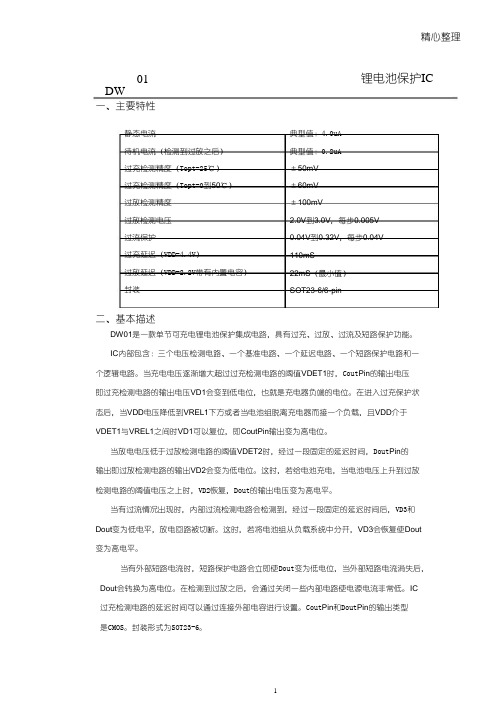
精心整理DW01锂电池保护IC一、主要特性静态电流待机电流(检测到过放之后)过充检测精度(Topt=25℃)过充检测精度(Topt=0到50℃)过放检测精度过放检测电压过流保护过充延迟(VDD=4.4V)过放延迟(VDD=2.2V带有内置电容)封装典型值:4.0uA典型值:0.2uA±50mV±60mV±100mV2.0V到3.0V,每步0.005V 0.04V到0.32V,每步0.04V 110mS22mS(最小值)SOT23-6/6-pin二、基本描述DW01是一款单节可充电锂电池保护集成电路,具有过充、过放、过流及短路保护功能。
IC内部包含:三个电压检测电路、一个基准电路、一个延迟电路、一个短路保护电路和一个逻辑电路。
当充电电压逐渐增大超过过充检测电路的阈值VDET1时,Cout Pin的输出电压即过充检测电路的输出电压VD1会变到低电位,也就是充电器负端的电位。
在进入过充保护状态后,当VDD电压降低到VREL1下方或者当电池组脱离充电器而接一个负载,且VDD介于VDET1与VREL1之间时VD1可以复位,即CoutPin输出变为高电位。
当放电电压低于过放检测电路的阈值VDET2时,经过一段固定的延迟时间,Dout Pin的输出即过放检测电路的输出VD2会变为低电位。
这时,若给电池充电,当电池电压上升到过放检测电路的阈值电压之上时,VD2恢复,Dout的输出电压变为高电平。
当有过流情况出现时,内部过流检测电路会检测到,经过一段固定的延迟时间后,VD3和Dout变为低电平,放电回路被切断。
这时,若将电池组从负载系统中分开,VD3会恢复使Dout 变为高电平。
当有外部短路电流时,短路保护电路会立即使Dout变为低电位,当外部短路电流消失后,Dout会转换为高电位。
在检测到过放之后,会通过关闭一些内部电路使电源电流非常低。
IC过充检测电路的延迟时间可以通过连接外部电容进行设置。
SDH系列恒流二极管(新)

SDH 系列恒流二极管SDH系列恒流二极管描述SDH 系列恒流二极管(CRD)采用士兰微电子平面 JFET 工艺技术制造。
先进的工艺及精细的设计使该系列产品具有较低的起 始稳流电压,稳定的恒流特性及很高的正向击穿电压。
该系列恒流二极管在应用时不需要外围其它辅助元 件,阳极和阴极之间具有较强的抗浪涌电流冲击的能力。
该系列产品主要应用在需要提供恒定电流的场合,可 应用于 LED 的恒流驱动灯驱动、电话线路模块等。
SDH 系列恒流二极管目前可提供 SOD-123 和 SOT223-3L 两种封装外形。
特点∗ ∗ ∗ ∗ ∗ 较低的起始稳流电压。
很高的动态阻抗。
恒流电流规格范围: 1mA – 40mA。
产品可并联使用,以扩充电流。
具有负温度系数,可在高温情况下保护 LED 管。
产品命名规则产品订货规格产 品 名 称 SDHXXXSTR SDHXXXHTR 封装形式 SOD-123 SOT-223-3L 打印名称 XXXS SDHXXXH 包装形式 卷盘式编带 编带杭州士兰微电子股份有限公司版本号:0.12010.05.24 共6页 第1页SDH 系列恒流二极管极限参数(除非特殊说明,TC=25°C)参 耗散功率 芯片对环境的热阻 最高工作电压 工作和存储结温 数 符 号 PD RθJA Vmax Tstg SOD-123 300 见下表 -30~+150 参数范围 350 单 位 mW °C/W V °C电参数(除非特殊说明,TC=25°C)规格 标识 102 152 202 272 352 452 562 822 103 123 153 183 213 253 303 恒流值范围 测试 电压 10V 10V 10V 10V 10V 10V 10V 10V 10V 10V 10V 10V 10V 10V 10V注起始饱和电流 Vk [ V ] 1.7 2.0 2.3 2.7 3.2 3.7 4.5 3.1 3.5 3.8 4.3 4.6 5.0 5.5 6.0注最高使用电 压电流比 IVMAX/Ip max.1.1 max.1.1 max.1.1 max.1.1 max.1.1 max.1.1 max.1.1 max.1.0 max.1.0 max.1.0 max.1.0 max.1.0 max.1.0 max.1.0 max.1.0温度系数 [%/°C] -0.10~ -0.37 -0.13~ -0.40 -0.15~ -0.42 -0.18~ -0.45 -0.20~ -0.53 -0.25~ -0.45 -0.25~ -0.53 -0.25~ -0.45 -0.25~ -0.45 -0.25~ -0.45 -0.25~ -0.45 -0.25~ -0.45 -0.25~ -0.45 -0.25~ -0.45 -0.25~ -0.45最高使用 电压 Vmax.(V) 100 100 100 100 100 100 100 50 50 50 50 50 45 45 45Ip(mA) 0.88~1.32 1.28~1.72 1.68~2.32 2.28~3.10 3.00~4.10 3.90~5.10 5.00~6.50 6.56~9.84 8~12 9.6~14.4 12~18 16~20 18~24 22~28 27~33Ik [ mA ] Min.0.8Ip Min.0.8Ip Min.0.8Ip Min.0.8Ip Min.0.8Ip Min.0.8Ip Min.0.8Ip Min.0.8Ip Min.0.8Ip Min.0.8Ip Min.0.8Ip Min.0.8Ip Min.0.8Ip Min.0.8Ip Min.0.8Ip注:脉冲测试,测试时间380μS。
崂应3012H-D型 便携式大流量低浓度烟尘自动测试仪-20150403
鲁制02000015号使用产品前请阅读使用说明书崂应3012H-D型便携式大流量低浓度烟尘自动测试仪使用说明书青岛崂山应用技术研究所崂应3012H-D 型便携式大流量低浓度烟尘自动测试仪使用说明书目 录1 产品概述 ......................................................................... 1 2 适用范围 ......................................................................... 1 3 采用标准 ......................................................................... 1 4 主要特点 ......................................................................... 1 5 工作原理 ......................................................................... 2 6 技术指标 ......................................................................... 3 7 工作条件 ......................................................................... 4 8 整机组成及使用连接图 ............................................................. 4 9 使用方法 ......................................................................... 9 10 安全保护及注意事项 ............................................................. 36 11 运输贮存及维护保养 ............................................................. 36 12 简单故障及排除方法 ............................................................. 37 13 公式 ........................................................................... 37 14 其他介绍 .. (40)安全警告警告本测试仪使用交流其他电源损伤仪器,甚至造成人身伤害!遇突发事件,请先断开电源!警告使用交流电源时,电源接地线应良好接地!仅适用于非防爆场合! 警告采样过程中,烟尘取样管和烟气含湿量取样管接地线应良好接地!崂应3012H-D型便携式大流量低浓度烟尘自动测试仪使用说明书崂应3012H-D型便携式大流量低浓度烟尘自动测试仪1 产品概述崂应3012H-D型便携式大流量低浓度烟尘自动测试仪(以下简称测试仪)是在崂应3012H自动烟尘(气)测试仪的基础上精心研制的新产品。
astm d3012标准中文版

ASTM D3012 标准简介1. ASTM D3012 是什么?ASTM D3012 是由美国材料和试验协会(American Society for Testing and Materials)发布的一项标准,主题为“石油产品中馏分合成馏程测定标准试验方法”。
它旨在为石油和润滑油行业的从业人员提供统一的测试方法,以确保产品的质量和性能。
2. 为什么要使用 ASTM D3012?石油产品中的馏分合成馏程是评估其蒸馏性能和沸点范围的重要参数。
采用统一的测试方法可以确保各种厂家生产的产品在质量和性能上达到相似的标准,有利于行业内产品的比较和竞争。
3. ASTM D3012 标准的内容ASTM D3012 标准主要包括以下内容:3.1 试验目的:明确了本标准的试验目的,即应用该标准来测定石油产品中馏分合成馏程。
3.2 试验范围:规定了该标准的适用范围,包括了各类石油产品和润滑油。
3.3 设备和仪器:详细介绍了进行馏程测定所需的设备和仪器,以及其规格和精度要求。
3.4 样品准备:包括了样品的采集、保存和准备的相关要求。
3.5 测试程序:详细描述了进行馏程测定的实验程序,包括设备的调试、样品的处理、试验条件的设定等内容。
3.6 结果计算:给出了测试结果的计算方法和数据处理的步骤。
3.7 报告:规定了测试结果的报告形式和内容要求。
4. ASTM D3012 标准的相关性ASTM D3012 标准是与石油和润滑油行业紧密相关的一项标准,它的发布和实施对于行业的发展和产品质量的保障具有重要意义。
该标准也与其他相关的 ASTM 标准相互关联,共同构成了一个完整的标准体系,为行业的发展和产品的质量提供着有力的支撑。
5. ASTM D3012 标准的应用价值ASTM D3012 标准的应用可以带来诸多价值:5.1 保障产品质量:统一的测试方法有利于不同厂家生产的产品在质量上达到相似的标准,提高产品的一致性和可比性。
旋转LED立体显示系统设计

0 引言随着信息时代的科学技术发展,信息显示技术百花齐放,并各有所长。
LED显示具有亮度高、清晰度高、色彩鲜艳、视角宽等优点。
其独特的优越性,促使其从广播、电力等高端专业领域扩展到能源、工业、民生、公共管理等领域。
在此之前,LED全彩显示主要用于广告媒体、运动场地、舞台背景和市政工程。
现国内市场已经有了面向电子创意作品的小型单色旋转LED显示屏,但尚不具备广泛的应用条件。
颜色显示单一,显示面积过小,无法实时更新数据,性价比低等缺点,使之无法广泛应用。
[1]结合现有条件,本设计旨在于设计一款更大显示面积,更丰富色彩显示,提高旋转显示系统的性价比的旋转LED显示系统。
1 设计原理旋转LED显示系统由三个部分构成:机械结构、STM32主控板和MBI5024LED驱动板。
显示板在主控板程序的控制下,进行LED灯的控制显示,并在机械结构电机的带动下,线动成面,成为一个曲面的显示屏。
电路结构如图1所示。
本设计以STM32单片机为核心控制芯片。
由电机带动主板旋转达到一定速度稳定旋转,使单排LED旋转起来,给人的视觉效果将是一个圆柱或一个球形,并通过红外模块来感知旋转速度及起始位置。
本显示屏拟选用具有超高处理速度,超低功耗,稳定性能STM32RCT6 单片机为主要控制元件,采用16位MBI5024LED驱动芯片,行扫描、列驱动进行动态扫描。
彩屏通过选用了三基色[2-3]混色的原理,通过时间混色法,LED 点亮不同颜色,然后在同一空间位置重合实现。
2 整体设计机械结构:机械结构可以称作为本设计的骨架,后续的硬件电路和其搭载的软件系统都需要一个牢固稳定的机械结构方能稳定高效的工作,尤其对于本设计来说,高速旋转的叶片更是高度需求一个设计精良的骨架。
主控板电路:主控电路板电路原理图如图2所示,主控电路板以贴片式封装的STM32F103RCT6单片机为主控芯片,从嵌入式最小硬件系统组成上来说,主控芯片STM32采用ARM Cortex内核,48KRAM,256KROM单片机上I/O口均被引出,为后续开发留下空间。
RFID在输血医学应用指南_上_

1
背景 第 2 次世界大战期间, 射频识别技术 ( radio frequency i-
dentification, RFID) 首先由英国皇家空军用于识别本国飞机 , 随着其可靠性提高和成本降低 , 人们对该技术的兴趣不断增 加。目前 RFID 的可靠性已足以支持生产工艺 、 医疗保健服 务和安全控制的优化。 国际输血协会信息技术工作委员会 ( International Society for Blood Transfusion Working Party on Information Technology, ISBT WPIT) 在全面分析 RFID 实验结果 后于 2006 年 决 定 成 立 RFID 特 别 工 作 组 ( Task Force on RFID) , 研究 RFID 发展现状, 起草 RFID 在输血医学应用推 荐指南。 1. 1 目的 提高医疗保健供应链效率 。 该指南在对 RFID 作 患者安全、 了技术回 顾 和 分 析 了 其 在 各 行 业 应 用 实 例 的 基 础 上 , 对 RFID 在输血医学应用的优缺点进行了全面评估 , 对 RFID 在 推荐标 输血这一特定领域运用的解决方案予以了充分验证 , 准还充分考虑了在将来实施中确保与相关行业的一致性和 兼容性。 1. 2 范围 该指南是为有意于 RFID 在输血医学中应用的 涵盖了从血袋生产到献血者直到患者的整个血液 人员编写, 产品供应链。该指南系第 1 版, 作者对所有评论、 改进建议 甚至批评都是开放的。 2 2. 1 什么是 RFID RFID 概述 RFID 是采用无线电磁波在电子标签和阅
a 不同规格的 RFID 标签; b 封装在塑料片、 钥匙、 腕带、 玻 璃瓶、 试管内的标 签; c 可 读 取条码 和 RFID 标签的 阅读 器; d 装有 RFID 阅读器模块的 PDA; e 门栅阅读器
