太阳能光伏电站的操作使用手册
屋顶分布式光伏电站安装指南

屋顶分布式光伏发电站安装指南户用分布式光伏发电站作为安装在家庭屋顶上的小型太阳能发电装置,安装方式和规模大小灵活方便。
规范的操作流程,确保您安心、省心、持续享用“屋顶银行”的发电收益。
一、混凝土基础安装按施工方式可分为:预制水泥基础和直接浇筑基础。
根据其大小可分为:独立底座基础和复合底座基础。
使用范围:混凝土平面屋顶。
优点:承载能力强,抗洪抗风效果好,受力可靠,不破坏水泥屋顶,强度好,精度高,且施工简单、方便、不需要大的施工设备。
缺点:增加屋顶的负荷,所需的钢筋混凝土量大、人工多、施工周期长,整体造价较高。
(1)独立底座基础独立底座为前后支架分开放置在混凝土平面屋顶上,独立底座按柱体形状分为方形柱、圆形柱。
a.方形柱方形柱基座从连接方式上分为:支架与水泥基础基座螺丝连接、支架连同水泥基础一起浇筑、支架直接压在混凝土基础凹槽下、混凝土直接放置在支架上。
①支架与水泥基础基座螺丝连接②支架连同水泥基础一起浇筑③支架直接压在混凝土基础凹槽下b.圆形柱圆形柱基座从连接方式上分为:支架与混凝土基础基座螺丝连接、支架连同水泥基础一起浇筑。
①支架与水泥基础基座螺丝固定连接②支架连同水泥基础一起浇筑(2)复合底座基础复合底座基础也称条形基础,将前后支架连接为一体,具有更好的抵抗载荷能力。
其与支架的连接方式可分为:支架与混凝土基础基座螺丝连接和支架连同水泥基础一起浇筑。
①支架与混凝土基础基座螺丝连接②支架连同水泥基础一起浇筑二、夹具安装材质可分为:铝型材、热镀锌钢、铝合金、不锈钢等。
适用范围:主要应用于彩钢瓦屋顶和琉璃瓦斜屋顶。
特点:重量轻、成本较低、可靠性高、安装便捷。
由于彩钢的结构种类多,夹具种类也较多,下面只列举部分夹具类型。
(1)彩钢瓦的安装夹具(夹持)适用彩钢瓦类型:角驰三型、直立锁边结构。
(2)马鞍支座适用彩钢瓦类型:角驰三型、直立锁边结构、梯形结构。
与彩钢瓦的连接方式分为:粘接和螺栓固定。
①粘接②螺栓固定(3)琉璃瓦挂钩固定基①挂钩用螺栓固定于横梁上②挂钩用膨胀螺栓固定于混凝土楼板上三、支架与屋顶粘接安装①支架直接接入楼板②支架底座用建设胶粘接于屋顶③金属支架嵌入式粘接于屋顶此安装方式主要应用于混凝土斜屋顶和混凝土拱形屋顶。
太阳能发电器操作手册说明书
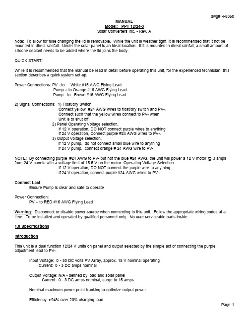
MANUALModel: PPT 12/24-3Solar Converters Inc. - Rev. ANote: To allow for fuse changing the lid is removable. While the unit is weather tight, it is recommended that it not be mounted in direct rainfall. Under the solar panel is an ideal location. If it is mounted in direct rainfall, a small amount of silicone sealant needs to be added where the lid joins the body.QUICK START:While it is recommended that the manual be read in detail before operating this unit, for the experienced technician, this section describes a quick system set-up.Power Connections: PV - to White #16 AWG Flying LeadPump + to Orange #16 AWG Flying LeadPump - to Brown #16 AWG Flying Lead2) Signal Connections: 1) Float/dry SwitchConnect yellow #24 AWG wires to float/dry switch and PV-,Connect such that the yellow wires connect to PV- whenUnit is to shut off.2) Panel Operating Voltage selection,If 12 V operation, DO NOT connect purple wires to anythingIf 24 V operation, Connect purple #24 AWG wires to PV-.3) Output Voltage selection,if 12 V pump, do not connect small blue wire to anythingif 24 V pump, connect orange # 24 AWG wire to PV-NOTE: By connecting purple #24 AWG to PV- but not the blue #24 AWG, the unit will power a 12 V motor @ 3 amps from 24 V panels with a voltage limit of 15.5 V on the motor. Operating Voltage SelectionIf 12 V operation, DO NOT connect the purple wire to anything.If 24 V operation, connect purple #24 AWG wires to PV-.Connect Last:Ensure Pump is clear and safe to operatePower Connection:PV + to RED #16 AWG Flying LeadWarning: Disconnect or disable power source when connecting to this unit. Follow the appropriate wiring codes at all time. To be installed and operated by qualified personnel only. No user serviceable parts inside.1.0 SpecificationsIntroductionThis unit is a dual function 12/24 V units on panel and output selected by the simple act of connecting the purple adjustment lead to PV-.Input Voltage: 0 - 50 DC volts PV Array, approx. 15 V nominal operatingCurrent: 0 - 3 DC amps nominalOutput Voltage: N/A - defined by load and solar panelCurrent: 0 - 3 DC amps nominal, surge to 15 ampsNominal maximum power point tracking to optimize output powerEfficiency: >94% over 20% charging loadTransient protected - input and outputTemperature range: -40 C to +60 CStart Current: 15 Amps for 10 secondsFloat/Dry Switch: On/off function is accomplished by connecting the yellow signal wires to PV- with a float/dry switch connection.Fuse: 5 amp automotive type fuse2.0 Power Connections2.1 Pump ConnectionUsing wire of sufficient amperage for the PUMP load connection #16 AWG or better connect the positive of the pump to the Orange Power lead. Similarly connect the negative of the pump to the Brown.2.2 Input Power ConnectionUsing wire of sufficient amperage for the input power (min. #16 AWG) connect the negative of the solar panel to the White terminal. Connect the positive of the solar panel (do this as the last connection) to the RED Power Lead.3.0 Signal Connections3.1 Operating VoltageThis pump driver is a dual 12/24-pump driver.1) To operate at 12 V: DO NOT connect the purple or blue wire to anything.2) To operate at 24 V: Connect the purple wire and blue wire to PV-.3) To operate a 12 V pump from 24 V panels, connect the purple wire only to PV-.3.2 Float Switch OperationTo turn the unit off, connect the yellow lead to a float/dry switch or similar device that connects the leads to PV- when it is desired to turn off the unit.Application NotesIt is highly recommended an external fuse or over temperature device is incorporated. This unit is quite capable of putting a continuous 15 amps into a stalled motor even from only 1 amps worth of solar panels, resulting in motor burnout.*****WARRANTYThe product is warranted to be free from defects in material and workmanship for a period of one (1) year from the date of purchase by a retail customer. The purchase date must be evi denced by a valid and original sales receipt. In lieu ofsales receipt, factory will use code date on its label. Removal of the Solar Converters Inc. label or serial number will void the warranty.Product liability, except where mandated by law, is limited to repair or replacement at the manufacturer's discretion. No specific claim of merchantability or use shall be assumed or implied beyond what is printed on the manufacturers printed literature. No liability shall exist from circumstances arising from the inability to use the product, or its inappropriateness for any specific purpose or actual use, or consequences thereof for any purpose. It is the user's responsibility to determine the suitability of the product for any particular use. Solar Converters Inc. shall not be liable for any damages or any kind including without limitation, special, incidental or consequential obligations and liabilities of Solar Converters Inc. and the remedies of Buyer set forth herein shall be Solar Converters Inc. sole and exclusive liability. Failure to provide a safe and correct installation, safe operation, or care for the product will void the warranty. Personal safety, and compatibility with any other equipment is the ultimate responsibility of the end user. Any returned product that shows significant evidence of abuse may not be covered by this warranty. Installation must be preformed by a personwith qualification to insure safe and effective operation and the installation thereof certifies that the installer has the technical qualifications to do so.Solar Converters Inc. cannot guarantee the compatibility of its products with other components used in conjunction with Solar Converters Inc. products, including, but not limited to, solar modules, batteries, and system interconnects, and such loads as inverters, transmitters and other loads which produce “noise” or electromagnetic interference, in excess of the levels to which Solar Converters Inc. products are compatible. Solar Converters Inc. shall not assume responsibility for any damages to any system components used in conjunction with Solar Converters Inc. products nor for claims for personal injury or property damage resulting from the use of Solar Converters Inc. products or the improper operation thereof or consequential damages arising from the products or use of the products.The warranties set forth herein are Solar Converters Inc. sole and exclusive warranties for or relating to the goods. Seller neither makes nor assumes any warranty or merchantability, any warranty fitness for any particular purpose, or any other warranty of any kind, express, implied or statutory. Solar Converters Inc. neither assumes nor authorizes any person or entity to assume for it any other liability or obligation in connection with the sale or use of the goods, and there are no oral agreements or warranties collateral to or affecting the sale of the goods.WARRANTY CLAIM PROCEDUREIn the event of product failure, follow this warranty claim procedure.1. Make sure the problem you are having is actually due to the suspected product and not some other part of the system. You may call technical support for advanced troubleshooting assistance.2. If you determine that a Solar Converters Inc. product is actually defective, describe on paper, in detail theexact nature of the failure.3. The product must be accompanied by proof of the date of purchase satisfactory to Solar Converters Inc.4. Return the product and description to the business office address, along with your address and a daytime phone number. Purchasers must prepay all delivery costs or shipping charges as well as any other charges encountered, in shipping any defective Solar Converters Inc. product under this warranty policy. No shipment will be accepted Freight Collect.5. Any return shipment from Solar Converters Inc. will be via Canada Post. Foreign shipments will ship best way. Special shipping arrangements are available at the customer's expense.。
CPS SCA630 500KTL-H CN 光伏并网逆变器使用手册说明书

CPS SCA系列光伏并网逆变器CPS SCA630/500KTL-H/CN安装使用手册上海正泰电源系统有限公司目录开始前请仔细阅读本用户手册 (1)第一章安全说明 (3)第二章总体介绍 (7)2.1 并网光伏系统 (7)2.2 系列型号说明 (7)2.3 逆变器电路结构 (8)2.4 逆变器选配功能 (8)2.5 外观说明 (9)第三章安装 (10)3.1 基本要求 (10)3.2 供货范围 (10)3.3 安装工具清单 (11)3.4 机械安装 (11)3.4.1 外形尺寸 (11)3.4.2 逆变器安装要求 (12)3.4.3 逆变器安装现场搬运 (15)3.5 电气连接 (18)3.5.1 电气连接前准备 (18)3.5.2 直流连接 (20)3.5.3 交流连接 (23)3.5.4 接地连接 (26)3.5.5 通讯连接 (27)3.5.6 外接辅助电源和干接点连接 (28)第四章运行操作 (29)4.1 上电前开机检查 (29)4.2 开机流程 (29)4.3 开机与停机 (30)4.4 工作模式 (33)4.5 并网发电 (34)4.6 故障停机 (34)4.7 故障分析与排除 (34)4.8 滤网更换 (38)第五章人机界面 (39)5.1 触摸屏显示简介 (39)5.2 状态指示 (39)5.3 界面及菜单功能 (40)5.3.1 首页 (40)5.3.2 运行信息 (41)5.3.3 当前故障 (43)5.3.4 历史记录 (44)5.3.5 逆变器参数 (45)5.3.6 系统参数 (50)5.3.7 版本信息 (52)5.3.8 电力调度 (52)第六章技术数据 (54)第七章质量保证 (56)7.1 质保期 (56)7.2 责任豁免 (56)7.3 质量条款(保修条款) (56)第八章回收报废 (57)附录Ⅰ:有毒有害物质或元素名称及其含量表 (58)附录Ⅱ:机器选型说明 (59)开始前请仔细阅读本用户手册尊敬的用户,感谢您选购使用上海正泰电源系统有限公司研发生产的CPS SCA系列光伏并网逆变器CPS SCA630/500KTL-H/CN(本手册中以下简称为“逆变器”)产品。
光伏电站运维手册
招标文件第三卷【技术文件】说明1、本技术文件中,薄膜电池组件有关要求不适用于本项目,在本项目中不允许使用薄膜电池组件.目录磋商文件第三卷【技术文件】 (1)光伏扶贫技术指南 (5)户用光伏电站使用手册 (6)一、注意事项 (8)二、日常维护 (9)三、常见问题 (9)四、紧急情况 (11)光伏电站专业运维手册 (13)前言 (14)目录 (15)1、概况 (16)2、运维人员要求 (16)3、光伏发电系统构成 (16)4、一般要求 (17)5、组件的维护 (18)6、配电箱的维护 (18)7、逆变器的维护 (20)8、支架的维护 (21)9、电缆及接头的维护 (22)10、接地与防雷系统 (22)11、数据监控系统 (24)12、光伏系统与建筑物结合部分 (29)13、光伏系统定期确认检验 (29)光伏电站技术指南 (32)目录 (33)一、说明 (34)二、规划选址 (34)三、设计要求 (34)四、设备选型 (37)五、系统接入 (39)六、支架系统安装 (39)七、系统施工 (40)八、产品检测 (45)运维、验收、培训 (52)一、运行维护服务 (52)二、工程验收 (52)三、培训方案 (55)国家相关规范 (56)一、《光伏制造行业规范条件(2015年本)》 (56)二、国能新能【2015】194号(“领跑者计划”) (62)光伏扶贫技术指南(供参考)安徽省发展改革委安徽省能源局安徽省电力公司户用光伏电站使用手册(供参考)目录一、注意事项 (8)二、日常维护 (9)三、常见问题 (9)四、紧急处理措施 (11)本手册主要针对5kWp以下分布式电站用户日常维护之用,请用户严格遵守。
一、注意事项1、配电装置上如有此种标识位置,请勿触摸,以免发生触电危险.2、用户切勿拆卸设备及配电装置,以免发生危险。
3、当紧急情况发生或者家用电网检修改造时,应先断开空气开关,再断开断路器;当紧急情况解决或者检修改造完成后,先闭合断路器,再闭合空气开关.图示如下:4、切勿在光伏组件上或阵列南面(前面)晾晒衣服和其他物品,以免造成触电危险或火宅,且阴影遮挡会影响发电量,降低自身发电收益。
太阳能充电器操作指南说明书

Installation andoperating instructionsSolar charge controller 10 A / 15 A / 20 A / 30 A1. About this manualThese operating instructions are part of the product.X Read these operating instructions carefully before use,X keep them over the entire lifetime of the product,X and pass them on to any future owner or user of this product.1.1 ApplicabilityThis manual describes the installation, function, operation and maintenance of the solar charge controller.Further technical information is provided in a separate technical manual.1.2 UsersThese operating instructions are intended for end customers. A technical expert must be consulted in cases of uncertainty.1.3. Description of symbolsSafety instructions are identified as follows:Type, source and consequences of the danger!X Measures for avoiding dangerInstructions relating to the functional safety of the system are in bold type.2. Safety2.1 Proper usageThe solar charge controller may only be used in PV systems for charging and controlling lead-acid batteries in accordance with this operating manual and the charging specifi-cations of the battery manufacturer.2.2 Improper usageNo energy source other than a solar generator may be connected to the solar charge controller. No mains devices, diesel generators or wind generators may be connected. Do not connect any defective or damaged measuring equipment.2.3 General safety instructionsX Follow the general and national safety and accident prevention regulations.X Never alter or remove the factory plates and identification labels.X Keep children away from PV systems.X Never open the device.2.4 Other risksDanger of fire and explosionX Do not use the solar charge controller in dusty environments, in the vicinity of solvents or where inflammable gases and vapours can occur.X No open fires, flames or sparks in the vicinity of the batteries.X Ensure that the room is adequately ventilated.X Check the charging process regularly.X Follow the charging instructions of the battery manufacturer.Battery acidX Acid splashes on skin or clothing should be immediately treated with soap suds and rinsed with plenty of water.X If acid splashes into the eyes, immediately rinse with plenty of water. Seek medical advice.2.5 Fault behaviourOperating the solar charge controller is dangerous in the following situations:• The solar charge controller does not appear to function at all.• The solar charge controller or connected cables are visibly damaged.• Emission of smoke or fluid penetration.• When parts are loose.X In these cases immediately remove the solar charge controller from the solarmodules and battery.3. Description3.1 FunctionsThe solar charge controller• monitors the state of charge of the battery bank, • controls the charging process,• controls the connection/disconnection of loads.This optimises battery use and significantly extends its service life.A battery charging algorithm protects the battery from harmful states. Activation of the three deep discharge functions (LVW, LVD and LVR) is dependent upon the state of charge (SOC). The switching thresholds lie within the corresponding voltage window in accordance with the discharge or charging current.3.2 Construction3.3LED displaysThe solar charge controller consists of the following components:1. info LED2. 4 LEDs for displaying the state of charge (red, yellow, green 1 and green 2)3. terminal block for connecting the solar module4. terminal block for connecting the battery5. terminal block for connecting the loads loads4. InstallationDanger of explosion from sparking! Danger of electric shock!X The solar charge controller may only be connected to the local loads and the bat-tery by trained personnel and in accordance with the applicable regulations.X Follow the installation and operating instructions for all components of the PV sys-tem.X Ensure that no cables are damaged.4.1 Mounting the solar charge controller4.1.1 Mounting location requirements• Do not mount the solar charge controller outdoors or in wet rooms.• Do not subject the solar charge controller to direct sunshine or other sources of heat.• Protect the solar charge controller from dirt and moisture.• Mount upright on the wall (concrete) on a non-flammable substrate.• Maintain a minimum clearance of 10 cm below and around the device to ensure unhindered air circulation.• Mount the solar charge controller as close as possible to the batteries (with a safety clearance of at least 30 cm).4.1.2 Fastening the solar charge controllerX Mark the position of the solar charge controller fastening holes on the wall.X Drill 4 Ø 6 mm holes and insert dowels.X Fasten the solar charge controller to the wall with the cable openings facing down-wards, using 4 oval head screws M4x40 (DIN 7996).4.2 Connection4.2.1 Preparing the wiringThe cross section of the connection cable depends on the power output of the solar charge controller.The table above applies to the following cable lengths:• 10 m solar module connection cable• 2 m battery connection cable• 5 m load connection cableConsult a dealer if the specified cable lengths are inadequate.An additional external fuse (not provided) must be connected to the battery con-nection cable, close to the battery pole.The external fuse prevents cable short circuits. A 40 A fuse can be used for all controller types.4.2.2 ConnectionDanger of explosion from sparking! Danger of electric shock!Solar modules generate electricity under incident light. The full voltage is present, even when the incident light levels are low.X Protect the solar modules from incident light during installation, e.g. cover them. X Never touch uninsulated cable ends. X Use only insulated tools.X Ensure that all loads to be connected are switched off. If necessary, remove thefuse. X Connections must always be made in the sequence described below.1st step: Connect the batteryX Label the battery connection cables as a plus cable (A+) and aminus cable (A–).X Lay the battery cables in parallel between the solar charge control-ler and the battery.Xterminals on the solar charge controller (with the battery symbol). X If necessary, remove any external fuse.X Connect battery connection cable A+ to the positive pole of the battery. X Connect battery connection cable A– to the negative pole of the battery. X Replace the external fuse in the battery connection cable.X If the connection polarity is correct, the info LED illuminates green.2nd step: Connect the solar moduleX Ensure that the solar module is protected from incident light. X Ensure that the solar module does not exceed the maximum per-missible input current.X Label the solar module connection cables as a plus cable (M+) anda minus cable (M–).X Lay both solar module connection cables in parallel between the solar module andthe solar charge controller.X First connect the M+ solar module connection cable to the correct pole of the leftpair of terminals on the solar charge controller (with the solar module symbol), then connect the M– cable.X Remove the covering from the solar module.Connection sequence1. battery2. solar module3. loads3rd step: Connect loadsNotes• Connect loads that must not be deactivated by the solar chargecontroller deep discharge protection, e.g. emergency lights or radioconnection, directly to the battery.• Loads with a higher current consumption than the device outputcan be directly connected to the battery. However, the solar chargecontroller deep discharge protection will no longer intervene. Loadsconnected in this manner must also be separately fused.X Label the load connection cables as a plus cable (L+) and a minus cable (L–).X Lay the load connection cables in parallel between the solar charge controller and the loadX First connect the L+ load cable to the correct pole of the right pair of terminals on the solar charge controller (with the lamp symbol), then connect the L– cable.X Replace the load fuse or switch on the load.4th step: Final workX Fasten all cables with strain relief in the direct vicinity of the solar charge controller (clearance of approx. 10 cm).4.2.3 GroundingThe components in stand-alone systems do not have to be grounded – this is not stand-ard practice or may be prohibited by national regulations (e.g.: DIN 57100 Part 410: Prohibition of grounding protective low voltage circuits). Consult the technical manual for more information.4.2.4 Lightning protectionIn systems subjected to an increased risk of overvoltage damage, we recommend installing additional lightning protection / overvoltage protection to reduce dropouts. Consult the technical manual for more detailed information.5. OperationThe solar charge controller immediately begins operation once the battery is connected or the external fuse is inserted.The displays of the solar charge controller show the current operating mode. User intervention or user settings are not required.Protection functionsThe following integrated protection functions of the solar charge controller ensure that the battery is handled as gently as possible.The following protection functions are part of the basic function of the controller:• Overcharge protection• Deep discharge protection• Battery undervoltage protection• Solar module reverse current protectionThe following installation faults do not destroy the controller. After correcting the fault, the device will continue to operate correctly:• Protection from solar module short circuits / incorrect solar module polarity1)• Protection from short circuits at the load output or excessive load current• Protection from battery connection with incorrect polarity• Protection from solar module overcurrent• Protection from device overtemperature• Protection from overvoltage at the load output• Protection from the wrong connection sequence1) The reverse-polarity protection of the solar module in a 24 V system is only provided up to an open-circuit module voltage of 36 V.6. MaintenanceThe solar charge controller is maintenance-free.All components of the PV system must be checked at least annually, according to the specifications of the respective manufacturers.X Ensure adequate ventilation of the cooling element.X Check the cable strain relief.X Check that all cable connections are secure.X Tighten screws if necessary.X Terminal corrosion7.Faults and remediesLoad cannot be operated+info LED flashes red+2. green LED flashes • load output is switched offdue to excessive batteryvoltagethe load output automaticallyswitched on again as soon asthe battery voltage lies withinthe permissible range• incorrect grounding X check the grounding• external charging source isnot voltage-limitedX check the external chargingsourceX if necessary, switch off exter-nal charging sourcesLoad cannot be operated+info LED illumi-nates green • defective load or installationerrorX connect load correctlyX replace loadBattery is not charged • solar module not connected X connect the solar module • solar module connected withincorrect polarityX connect the solar modulewith the correct polarity• short circuit at solar moduleinputX correct the cause of the shortcircuit• incorrect solar modulevoltageX use a solar module of thespecified voltage• solar module defective X replace the solar moduleBattery display jumps quickly • large pulse current X tune the current consump-tion to match the batterycapacity• battery is defective X replace the battery8. T echnical dataNOTE:Technical data that varies from the above is given on a device label. Subject to change without notice.*If the battery voltage is less than 9 V, the controller switches off and cannot recharge the battery itself, even if sufficient power is available from the module.9. Legal guaranteeAccording to the German legal requirements, for this product the customer has a2 year legal guarantee.The seller will remove all manufacturing and material faults that occur in the product during the legal guarantee period and affect the correct functioning of the product. Natural wear and tear does not constitute a malfunction. Legal guarantee does not apply if the fault can be attributed to third parties, unprofessional installation or com-missioning, incorrect or negligent handling, improper transport, excessive loading, use of improper equipment, faulty construction work, unsuitable construction location or improper operation or use. Legal guarantee claims shall only be accepted if notification of the fault is provided immediately after it is discovered Legal guarantee claims are to be directed to the seller.The seller must be informed before legal guarantee claims are processed. For processing a legal guarantee claim an exact fault description and the invoice / delivery note must be provided.The seller can choose to fulfil the legal guarantee either by repair or replacement. If the product can neither be repaired nor replaced, or if this does not occur within a suitable period in spite of the specification of an extension period in writing by the customer, the reduction in value caused by the fault shall be replaced, or, if this is not sufficient taking the interests of the end customer into consideration, the contract is cancelled. Any further claims against the seller based on this legal guarantee obligation, in particular claims for damages due to lost profit, loss-of-use or indirect damages are excluded, unless liability is obligatory by German law.。
太阳能光伏汇流箱操作说明
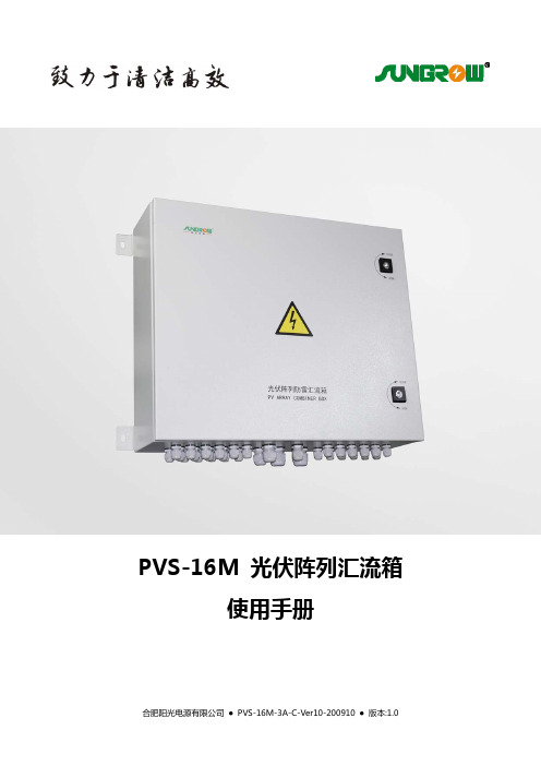
PVS-16M光伏阵列汇流箱使用手册合肥阳光电源有限公司 ● PVS-16M-3A-C-Ver10-200910 ● 版本:1.0目录1. 符号解释 (1)2. 安全说明 (2)3. 简介 (3)4. 基本结构 (4)5. 安装与使用 (5)6. 技术数据 (11)7. 附录 (12)7.1. 质量保证 (12)7.2. 联系我们 (12)合肥阳光电源有限公司PVS-16M16汇流箱使用手册11. 符号解释为了更好的使用本手册,请仔细阅读以下符号说明。
警告!此符号标识对于如果不当操作则可能对用户的安全产生危险和(或)可能造成重大硬件损坏的注意事项或者说明。
说明! 此符号标识使得系统良好工作所需的重要注意事项。
合肥阳光电源有限公司PVS-16M16汇流箱使用手册22. 安全说明安装前请仔细阅读本手册,若未按本手册中的说明进行安装而出现设备损坏,本公司有权不进行质量保证。
警告!所有的操作和接线请专业电气或机械工程师操作。
警告! 安装时,除了接线端子外,请不要动机箱内部的其它部分。
警告! 所有的操作和接线必须符合所在国和当地的相关标准要求。
警告!白天安装光伏组件时,应用不透光的材料遮住光伏组件,否则在太阳光下,光伏组件会产生很高的电压,可能导致电击危险。
合肥阳光电源有限公司3.简介对于大型光伏并网发电系统,为了减少光伏组件与逆变器之间连接线,方便维护,提高可靠性,一般需要在光伏组件与逆变器之间增加直流汇流装置。
本公司的光伏阵列防雷汇流箱系列产品就是为了满足这一要求而特别设计的,可与本公司的光伏逆变器产品相配套组成完整的光伏发电系统解决方案。
使用光伏汇流箱,用户可以根据逆变器输入的直流电压范围,把一定数量的规格相同的光伏组件串联组成1个光伏组件串列,再将若干个串列接入光伏阵列防雷汇流箱,通过防雷器与断路器后输出,方便了后级逆变器的接入。
建议用户在安装及使用时遵守必要的安全规范,为了保证人身安全与降低危险性,用户需要遵守手册中提到的安全措施。
SUNTECH 光伏组件安装指南说明书

拆包后的组件存放,须注意: 现场临时放置组件时,组件正面朝下放置在平整的表面上,必须使用软性材料加以缓冲,如纸板、泡沫纸等材料,且多
块组件摆放,需上下四角位置一致,严禁任何错位。 需要组件斜立在墙面,尽量使组件的两条长边完全与地面和墙面接触,在接触位置放置海绵等柔软物品,最多叠放组件
始终遵守组件支架的说明指导和安全防范措施。
请勿尝试在组置在支撑结构上。
将组件安装于屋顶前,请确保屋顶的结构合理。另外,任何需要安装组件的屋顶必须密封处理防止漏水。
将组件安装于立柱上时,选择的立柱和组件支撑结构必须可以承受当地可能的风载荷。
请避免较小倾斜角,否则会引起灰尘积聚在支架边缘的玻璃。
块。 严禁将组件靠着支架,或用木板抵挡背面,易导致组件受损。 禁止一切外力及外物对组件玻璃单点进行撞击及磕碰,以防止组件爆裂。
版本
不规范的组件存放将导致尚德质保失效。
操作安全
请勿抓住组件接线盒或引出线提起组件。 请勿站在或踩在组件上。 请勿使组件掉落或使物体坠落于组件上。 请避免玻璃碎裂。请勿在组件上放置任何重物或尖锐物体。 组件要轻拿轻放。 禁止直接用手搬运双玻无框组件,须用四个或四个以上的吸盘搬运,保证组件受力均匀。 组件的搬运过程中须注意路面状况,不恰当的搬运、运输或安装可能损坏组件并使质保无效。 组件安装时如需抬高,禁止安装人员站在组件下方。 请勿尝试拆解组件及组件上的任何铭牌或元件。 请勿在组件玻璃或背板上使用油漆或粘合剂。 为避免损坏背板,请勿刮擦、撞击背板。 面板放于任何平面均要轻拿轻放,特别是将其放在角落时。 面板上的玻璃破损或背板损坏时将无法修复,禁止使用此类面板,因为接触此类面板平面或支架将导致触电。 只能在干燥环境中作业,且只能使用干燥的工具。请勿在未佩戴任何保护措施的条件下在潮湿的环境中作业。 如需在户外将未安装的组件存放一段时间,须始终遮盖组件并保证玻璃面向下,防止组件内部积水和连接器的损坏。
华为智能光伏手册说明书

版权所有 © 华为技术有限公司 2018。
保留一切权利。
非经华为技术有限公司书面同意,任何单位和个人不得擅自摘抄、复制本手册内容的部分或全部,并不得以任何形式传播。
商标声明、HUAWE I 、华为、是华为技术有限公司的商标或者注册商标。
在本手册中以及本手册描述的产品中,出现的其他商标、产品名称、服务名称以及公司名称,由其各自的所有人拥有。
免责声明本文档可能含有预测信息,包括但不限于有关未来的财务、运营、 产品系列、新技术等信息。
由于实践中存在很多不确定因素,可能导致实际结果与预测信息有很大的差别。
因此,本文档信息仅 供参考,不构成任何要约或承诺。
华为可能不经通知修改上述信息,恕不另行通知。
华为技术有限公司深圳市龙岗区坂田华为基地 电话: (0755) 28780808邮编: 518129版本:V2-(20181124)关注微信华为智能光伏华为相伴 幸福一生智能能源解决方案FusionHome 户用智能光伏持续创新投入, 保障长期技术领先赢得全球客户和消费者的认可与信赖全球智能光伏领导品牌融合全球领先技术, 铸就精品光伏2017年,公司销售收入达6036亿人民币,同比增长15.7%稳健的经营状况, 长期可持续经营亿2014100020003000400050006000201320152016201725年全生命周期有保障华为大品牌, 值得信赖25年全面保障2008~2017年累计研发投入2017年研发投入占公司收入14.9%以上累计专利授权截至2017年12月31日0102全球部署,截止2018年8月2015至2017连续3年全球发货排名培训中心7*12 5*9 5*9为全球1/3以上的人口提供产品和服务智能手机全球零售市场份额TOP3, 年出货量1.39亿台路由器、交换机全球市场份额第一通讯基础网络设备全球市场份额第一海思芯片无线技术大数据分析云计算0304FusionHome智能能源解决方案全景图FusionHome智能能源解决方案通过将信息技术、互联网技术与光伏技术跨界融合,集成高效光伏发电,即插即用储能接口,并以用户体验为中心,实现可视化家庭能源管理,场景化、简单化一键用电,为客户带来更安全、多发电、好管理的美好生活体验。
太阳能光伏电站操作使用手册
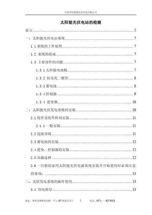
太阳能光伏电站操作使用手册资料来源:河南华阳能源发电科技有限公司目录一:太阳能光伏电站系统 (1)1.1系统的工作原理 (1)1.2系统的组成 (1)1.3主要部件的功能 (1)1.3.1太阳能电池板 (1)1.3.2防反充二极管 (2)1.3.3蓄电池 (2)1.3.4控制器 (2)1.3.4逆变器 (3)二:太阳能光伏发电系统的安装 (4)2.1组件及组件阵列安装 (4)2.1.1一般安装 (4)2.2连接导线 (4)2.3蓄电池的安装 (5)2.4逆变,控制器的安装 (5)2.5负载选择 (5)2.6一台新的家用太阳能光伏电源系统安装并开始使用时必须注意的事项: (5)三:光伏发电系统的操作使用 (6)3.1用电指导 (6)3.2光伏电站供电的操作使用 (6)3.2.1控制柜的操作使用 (6)3.2.2逆变器的操作使用 (10)四:太阳能光伏发电系统管理维护 (10)4.1独立型太阳能光伏电站管理 (10)4.1.1人员配置 (10)4.1.2值班制度 (10)4.1.3交接班制度 (11)4.1.4生产管理 (11)4.1.4.5电站应制订必要的奖罚制度 (11)4.2太阳能电池方阵维护管理 (11)4.2.1太阳能电池采光面 (11)4.2.2太阳能电池板周边环境 (12)4.2.3太阳能电池板的安装 (12)4.2.4太阳能电池板支架检查 (12)4.2.5太阳能电池板参数检测 (12)4.2.6外界的环境影响 (12)4.2.7太阳能部件的接头的检测和处理 (12)4.3蓄电池组维护管理 (12)4.3.1蓄电池的工作环境 (12)4.3.2电池安装 (13)4.3.3日常检查与维护 (13)4.3.4技术保安 (13)4.4逆变器维护管理 (14)4.4.1逆变器操作使用 (14)4.4.2逆变器维护检修 (14)4.5配电柜的布局图及其操作方式 (15)4.5.1配电柜的布局图形。
光伏系统产品说明说明书

Specifications are subject to change without notice (14.08.2017)1PhotoelectricsSmall through beam photo elec t ric switch. Range up to 50 m. 3 beam angles.Wa t erproof, for dirtyen v i ronment, i.e. water, dust, steam etc. To be used with amplifiers series S142. S143. 15 m shield e d cable, PVC. Ø 10 x 42 mm polycarbo n ate or M12 or M14 stainless s teel housing. Straight op t i c al axis.Product De s crip t ionType SelectionHousingRated Optical Ordering no.: Ordering no.: diameteroperating angle Emitter Receiverdist. (S n )Ø 10 mm 2° MOFR 5° MOFR-5 8° MOFR-8 20 m 2° MOFT 20 20 m 5° MOFT 20-520 m 8° MOFT 20-8 50 m 2° MOFT 50M12 2° MOFR-M12-2 5° MOFR-M12-5 8° MOFR-M12-820 m 2° MOFT 20-M12-2 20 m 5° MOFT 20-M12-5 20 m 8° MOFT 20-M12-850 m2°MOFT 50-M12-2M14 8° MOFR-M14-820 m 8° MOFT 20-M14-8• Built-in lens: 2°, 5° or 8°• Range: 20 m or 50 m • Modulated infrared light• High immunity to ambient light• For amplifier series S142. and S143.• Degree of protection IP 66/IP 67• For harsh environment • High penetration power • 15 m shielded PVC cable• Ø 10 mm polycarbonate housing or M12 or M14 stainless steelTypes MOFT, MOFRThrough-beam for Separate Amplifier Specifications Emitter2Specifications are subject to change without notice (14.08.2017)MOFT, MOFRWiring DiagramsDimensions8° types2° and 5° typesSpecifications are subject to change without notice (14.08.2017)3Delivery Contents• MOFT.. and MOFR• All M12types: 2 pcs. M12 nuts • All M14types: 2 pcs. M14 nuts• Packaging : Plastic bag, emitter and receiver packedseparatelyInstallation HintsRelief of cable strainProtection of the sensing faceSwitch mounted on mobile carrierTo avoid interference from inductive voltage/ current peaks, separate the prox. switch power cables from any other power cables, e.g. motor, contactor or solenoid cablesIncorrectCorrectThe cable should not be pulledA proximity switch should not serve as mechanical stopAny repetitive flexing of the cable should be avoidedMOFT, MOFRAccessories• Mounting bracket MBM01InstallationMounting1) When installing the sensors, make sure that the maximum range is not exceeded and if two separate systems are mounted close to each other place the sensors so crosstalk is avoided.2) To protect the receiver and the transmitter from damage, proper fittings must be used in the installation.3) Connect the receiver and the emitter to the dedicatedterminals on the S142... system.。
太阳能光伏电站的流程

太阳能光伏电站流程在一个地方建太阳能光伏电站,首先要进行当地太阳能资源评估,以此判断该地是否适宜建设太阳能光伏电站。
太阳能辐射分为总辐射、直接辐射、散射辐射,太阳能各项辐射数据要从附近气象站获得或在NASA上查找当地对应经纬度的各个气象数据。
具体太阳能发电系统主要包括以下几部分:太阳能电池组件、控制器、蓄电池、逆变器、负载等组成。
其中,太阳能电池组件和蓄电池为电源系统,控制器和逆变器为控制保护系统,负载为系统终端。
一、太阳能电池组件太阳能电池组件是发电系统中的核心部分,其作用是将太阳的辐射能直接转换为直流电,供负载使用或存贮于蓄电池内备用。
一般根据用户需要,将若干太阳能电池板按一定方式连接,组成太阳能电池方阵(阵列),再配上适当的支架及接线盒组成太阳能电池组件。
下图(图1)是我校太阳能光伏电站所用的太阳能电池组件:图1我校太阳能光伏电站的太阳能电池组件下面简单介绍太阳能电池片的种类及特点类型项目单晶硅多晶硅非晶硅转换效率12~17% 10~15% 6~8%使用寿命15~20年15~20年5~10年平均价格昂贵较贵较便宜稳定性好好差(会衰减)颜色黑色深蓝棕主要优点转换效率高、工作稳定,体积小。
工作稳定,成本低。
使用广泛。
价低,弱光性好,多数用于计算器,电子表等主要缺点成本高转换效率较低转换效率最低,会衰减。
相同功率的面积比晶体硅大一倍以上。
二、蓄电池蓄电池作用是将太阳能电池方阵发出直流电贮存起来, 供负载使用。
在光伏发电系统中, 蓄电池处于浮充放电状态。
白天太阳能电池方阵给蓄电池充电,同时方阵还给负载用电,晚上负载用电全部由蓄电池供给。
因此, 要求蓄电池的自放电要小, 而且充电效率要高, 同时还要考虑价格和使用是否方便等因素。
图2 我校太阳能光伏电站所用蓄电池蓄电池的种类及特点类别 项目 锂电池 镍镉电池镍氢电池免维护铅酸电池胶体普通酸液 充放电特性无记忆效应,使用时间长,重复充电可达1200次以上。
最全的分布式光伏电站运维手册
最全的分布式光伏电站运维手册光伏电站系统是由光伏组件(太阳能电池组件)、逆变器、汇流箱、配电箱、支架和连接导线等器件组成。
其中任何一个环节出现问题,都会影响整个电站的正常运行,轻则损失发电量,重则会引起火灾等重大损失。
据统计,光伏电站系统的常见故障中,组件、逆变器、汇流箱等直流侧设备故障占比高达90.18%,电缆、变压器、土建、升压站等交流侧设备故障占比为9.82%。
一、光伏电站系统常见的问题1、质量问题(1)产品设备质量问题:主要有光伏组件翻新、功率虚标、太阳能电池板以次充好、衰减严重;逆变器输出功率不足、老化;混凝土标号选错、浇筑尺寸不足;支架材料误差大、镀锌层锌量不够;线缆低配、载流量不足;配电设备使用混乱、元器件不符合标准等。
(2)施工安装质量问题:主要有施工安装过程中基础振捣不到位,钢筋笼绑扎不标准,支架螺栓安装节点不到位,线缆连接不规范、接触不良、虚接,组件安装不规范造成隐裂等。
2、日常管理(1)遮挡:主要有光伏阵列间遮挡以及建筑物(墙面、烟囱)、高压线、天线、基站、栏杆、太阳能热水器、树木和杂草遮挡等。
由于一块光伏组件的其中一块太阳能电池都会对整组组串的功率输出造成很大的影响。
遮挡最典型的后果是热斑效应和腐蚀效应。
热斑效应是指光伏组件遮挡的部分内部升温远超过未遮挡的部分,容易形成热斑,使组件烧坏,缩短组件的使用寿命,降低发电效率;腐蚀效应是指空气中的粉尘吸附大气中呈酸碱性的有害物质落在太阳能电池板上腐蚀其表面,还有引起阳光在表面形成漫反射,降低发电量。
(2)灰尘与积雪:灰尘就是悬浮在空气的微粒,来源于汽车尾气、工业污染、土壤扬尘等。
光伏组件安装在室外表面很容易沾染灰尘,不仅是灰尘,还有鸟粪、沙土、植物树叶、建筑溅渍、油污等,都会影响光伏组件发电效率。
同样的,雪落在光伏组件上也会变成阴影遮挡,造成光伏发电量损失。
当组件局部被遮挡时,被遮挡部分电池片的电流将低于其他电池片。
被遮挡部分还会成为电源的负载,将电能转换为热能并产生高温,发生“热斑效应”。
太阳能光伏电站的操作使用手册
1.3.1 太阳能电池板.......................................................................... 7 1.3.2 防反充二极管......................................................................... 8 1.3.3 蓄电池...................................................................................... 8 1.3.4 控制器...................................................................................... 9 1.3.4 逆变器................................................................................... 10 二:太阳能光伏发电系统的安装............................................................... 10 2.1 组件及组件阵列安装...................................................................... 11 2.1.1 一般安装................................................................................ 11 2.2 连接导线.......................................................................................... 11 2.3 蓄电池的安装.................................................................................. 12 2.4 逆变,控制器的安装...................................................................... 12 2.5 负载选择.......................................................................................... 12 2.6 一台新的家用太阳能光伏电源系统安装并开始使用时必须注意 的事项:................................................................................................. 13 三:光伏发电系统的操作使用................................................................... 13 3.1 用电指导......................................................................................... 13
光伏合闸顺序
光伏合闸顺序光伏发电系统是利用太阳能光能将其转化为电能的一种新能源技术。
在光伏电站中,光伏阵列的输出电能通过光伏逆变器转换为交流电能,并送入电网中供电使用。
然而,在发生故障、维护检修或其他需要断开光伏阵列与光伏逆变器连接的情况下,光伏合闸顺序变得十分重要。
光伏合闸顺序是确保光伏电站安全运行的重要步骤。
合闸顺序必须按照一定的规定进行操作,以避免过电压、过电流和其他电力设备损坏的风险。
下面将介绍合闸的正确顺序。
首先,合闸前需要确保光伏逆变器处于停机状态。
关闭逆变器的运行开关,以确保光伏发电系统不再向电网供电。
在某些光伏电站中,可能需要使用遥控开关或遥信来控制光伏逆变器的启动和停机。
在启动或停机操作之前,必须对逆变器进行测试,以确保其正常工作。
接下来,关闭光伏阵列的直流断路器。
该断路器位于光伏阵列与逆变器之间,用于切断光伏阵列产生的直流电能。
在光伏合闸顺序中,关闭直流断路器是一个重要的步骤,因为它可以保护光伏逆变器免受过载和电弧故障的影响。
在关闭直流断路器之后,需要打开光伏逆变器的旁路开关或分流开关。
这一步骤相当于将逆变器与光伏阵列分离,以确保光伏阵列的电压和电流不会影响逆变器的运行。
分流开关的操作必须小心谨慎,防止因过电压损坏光伏逆变器和其他电力设备。
最后,可以关闭光伏阵列的交流断路器。
这个步骤相当于切断逆变器输出的交流电能,离开之前向电网供电。
关闭交流断路器前,应注意检查电压和电流的状态,确保光伏逆变器已停机,并且不再向电网供电。
在进行光伏合闸顺序操作时,一定要遵守相关的操作规范和安全操作指南。
如果您不确定,最好请专业人员指导,以确保操作的准确性和安全性。
总之,光伏合闸顺序是光伏电站正常运行和安全操作的关键步骤。
确保在进行合闸操作前,将光伏逆变器停机、关闭光伏阵列的直流断路器、打开逆变器的旁路开关,并最后关闭光伏阵列的交流断路器。
通过按照正确的顺序进行操作,可以最大限度地减少故障和损坏的风险,确保光伏电站的稳定运行。
居民光伏发电用户使用手册

居民光伏发电用户使用手册国网蚌埠供电公司分布式光伏发电项目接入系统方案项目业主(用户)确认单X X公司(项目业主):你公司(项目业主)XX项目接入系统申请己受理,接入系统方案已制订完成,现将接入系统方案(详见附件)送达你处,请确认后将本单返还客户服务中心,我公司将据此提供项目接入电网意见函。
若有异议,请持本单到客户服务中心咨询。
项目单位:(公章)客户服务中心:(公章)项目个人:(经办人签字)分布式光伏发电项目并网验收和调试申请表告知事项:1.本表1式2份,双方各执1份。
2.具体验收时间将电话通知项目联系人。
本手册对居民分布式光伏并网项目中涉及的报装、结算和安全运行、使用进行了详解,确保居民分布式光伏并网项目的安全稳定运行。
本手册主要起草人:赵明、熊开斌、张金剑、报装部分1、居民家庭分布式电源并网申请材料:房产证(或 乡镇及以 上政府出 具的房屋 使用证明)并网申 请表申请人 身份证2、勘查和方案制定到营业 厅提供物业出具 同意建设 分布式电 源的证明 材料。
供电公司将按照约定的时间至现场查看接入条件,并在20 个工作日内答复接入系统方案。
3、 并网验收与调试工程竣工后,供电公司在受理并网验收及并网调试申请后,10个工作日内完成并网验收与调试。
4、 装表和合同签订供电公司与居民光伏发电用户签署关于购售电、供用电和 调度方面的合同,免费提供关口计量表和发电量计量用电能表; 调试通过后直接转入并网运行。
免费代为向政府能源主管部门进 行备案。
二、结算部分1. 分布式光伏发电项目结算原则和流程居民分布式光伏发电项目在完成并网后,电网企业营销部门________________________ )/ --------------------------- \客户确定现场勘查时间 (客户一定要在约定的时 间等候避免耽误)\ ___________________________ /供电公司受理申请后/X班组(供电所)工作人员 在2个工作日内联系客户 约定时间完成现场勘查负责按合同约定的结算周期(原则上不超过两个月)抄录分布式光伏发电项目上网电量和发电量;计算应付上网电费和补助资金,与分布式光伏发电项目业主确认;收取增值税发票或代开普通发票后,由财务部门核对一致后,按照合同约定的收款人账户信息及时通过转账方式支付上网电费和补助资金。
光伏发电操作规程
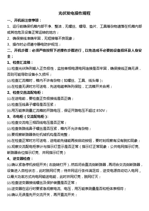
光伏发电操作规程一、开机前注意事项:1、运行前确保机箱内部干净、整洁,无螺丝、螺母、垫片、工具等杂物遗落在机箱内部或其他危及设备正常运转的地方;2、确保接线准确牢固,无短接等不良现象;3、操作时必须遵守静电防护规范;二、开机步骤:必须严格按照下述操作步骤进行,以免造成不必要的设备损坏及人身安全;1、检查汇流箱:⑴.检查光伏阵列输入正负极性,监控单相电源电网连接是否牢固,确保接线正确无误,否则可能导致设备永久损坏;⑵.检查汇流箱时,箱内不许有杂物(如螺丝、工具、线头等);⑶.在检查无误时方可送电,先送电磁串阵列保险,汇流箱开关合闸;2、检查交直流配电柜:⑴.在送电前,要检查正负极接线是否正确;⑵.检查压线鼻子螺母是否压紧;⑶.用万能表测量汇流箱的开路电压,保证开路电压不超过850V;3、市电柜(交流配电柜):⑴.检查交流电三相四线电压是否正常;⑵.检查各路线鼻子螺丝是否压紧,箱内不允许有杂物;⑶.要观察断路器各处机械机构是否完整;⑷.在检查正常时方可送电,送电前先储能再按启动按钮,要时刻观察有没有脱扣现象;⑸.观察交流配电柜表计与指示灯显示是否正常(指示灯正常现象:公共电网指示灯亮、断路器合位指示灯亮、并网指示灯亮)4、逆变器检查:⑴.确认紧急停机按钮开关(右旋转打开),然后闭合直流侧断路器,再闭合交流侧断路器,设备进入自检状态,此时脱网灯亮;待并网运行条件满足后,逆变电源自动切入电网,以最大功率方式向电网输送电能,此时并网灯亮,脱网灯灭;⑵.检查逆变器接线螺丝及保护装置是否正常;⑶.逆变器在运行时要紧急观察电流、电压,用万能表测量是否和柜体表相符;⑷.确认无误是先开交流开关,再开直流开关;三、设备运行方法:⑴.首次开机:按照以上步骤先后闭合直流、交流断路器,设备启动;此时脱网指示灯亮,表示电网未接入逆变器电源主回路,当逆变电源检测到光伏电压超过470Vdc时,逆变器电源启动,内部接触器动作,电网切入内部回路,拖网指示灯灭,此后逆变电源会自动追踪光伏电池最大功率点,实现最大功率并网;※注意:为了人身和设备安全,人为控制开关的频率不要太高,请在关机十分钟后再次打开逆变电源!⑵.自动关机:设备正常运行时,一直以最大功率方式向电网输出电能,当太阳光持续较弱(傍晚或者阴雨天)达到两分钟,逆变电源会关闭输出,进入低功耗模式,但此时并网灯依然亮,表示电网仍然接入内部主回路,当太阳光再次减弱,直至光伏电压低于430Vdc时,逆变电源断开电网连接,进入待机状态,此时脱网灯亮;如果需要停止逆变器电源,先断开直流侧断路器,然后直接拍打紧急停机按钮,等待大约十分钟后方可打开设备进行相应操作;⑶.自动运行:当太阳光逐渐加强时,光伏输出电压逐渐升高,当光伏输出电压高于470Vdc时逆变电源自动唤醒,由自动关机状态转入并网运行状态,以最大功率方式向电网输送电能;⑷.并网逆变电源具有多种保护措施,在故障消失后,逆变电源会自动投入运行,除非再次检测到故障;四、停机步骤:1、停机时先关闭逆变器电源,先断开直流侧断路器,再断开交流侧断路器,等大约十分钟后方可打开设备进行相应操作;2、最后进行停止市电柜电源;警告:按要求启动操作设备,违反操作规程将可能对人体造成致命伤害,甚至死亡!☞不要触摸与电网回路相关的端子和导体,避免电击!☞此操作只能有电气相关专业人员进行,严禁非电气人员进行操作,检修时必须做好安全防护!。
- 1、下载文档前请自行甄别文档内容的完整性,平台不提供额外的编辑、内容补充、找答案等附加服务。
- 2、"仅部分预览"的文档,不可在线预览部分如存在完整性等问题,可反馈申请退款(可完整预览的文档不适用该条件!)。
- 3、如文档侵犯您的权益,请联系客服反馈,我们会尽快为您处理(人工客服工作时间:9:00-18:30)。
目录《光伏电站的管理及维护》 (1)太阳能光伏发电站运行管理模式探讨2 (6)《光伏电站的管理及维护》从目前太阳能光伏电站的运行管理经验来看,要保证光伏发电系统安全、经济、高效运行,必须建立规范和有效的管理机制,特别是要加强电站的运行维护管理,建立完善的技术文件管理体系。
建立全面完整的技术文件资料档案,并设立专人负责电站技术文件的管理,为电站的安全可靠运行提供强有力的技术基础和数据支持。
目录一管理制度1.建立电站设备技术档案和设计施工图纸档案2.建立电站的信息化管理系统3.建立电站运行期档案4.建立运行分析制度二技术体系1. 光伏阵列2. 蓄电池组3. 各控制器及逆变器4. 防雷装臵5.低压配电线路三加强人员培训四建立通畅的信息通道一管理制度一.建立电站设备技术档案和设计施工图纸档案这是电站的基本技术档案资料,主要包括:1 设计施工、竣工图纸;验收文件;2 各设备的基本工作原理、技术参数、设备安装规程、设备调试的步骤;3 所有操作开关、旋钮、手柄以及状态和信号指示的说明;4 设备运行的操作步骤;5 电站维护的项目及内容;6 维护日程和所有维护项目的操作规程;7 电站故障排除指南,包括详细的检查和修理步骤等。
二.建立电站的信息化管理系统利用计算机管理系统建立电站信息资料,对每个电站建立一个数据库,数据库内容包括两方面,一是电站的基本信息,主要有:1 气象地理资料;交通信息;2 电站所在地的相关信息(如人口、户数、公共设施、交通状况等);3 电站的相关信息(如电站建设规模、设备基本参数、建设时间、通电时间、设计建设单位等)。
二是电站的动态信息,主要有:1 电站供电信息:用电户、供电时间、负载情况、累计发电量等;2 电站运行中出现的故障和处理方法:对电站各设备在运行中出现的故障和对故障的处理方法等进行详细描述和统计。
三.建立电站运行期档案这项工作是分析电站运行状况和制定维护方案的重要依据之一。
日常维护工作主要是每日测量并记录不同时间系统的工作参数,主要测量记录内容有:1 日期、记录时间;2 天气状况;环境温度;3 蓄电池室温度;4 子方阵电流、电压;5 蓄电池充电电流、电压;6 蓄电池放电电流、电压;7 逆变器直流输入电流、电压;8 交流配电柜输出电流、电压及用电量;9 记录人等。
当电站出现故障时,电站操作人员要详细记录故障现象,并协助维修人员进行维修工作,故障排除后要认真填写《电站故障维护记录表》,主要记录内容有:1 出现故障的设备名称、2 故障现象描述、3 故障发生时间、4 故障处理方法、5 零部件更换记录、6 维修人员、7 维修时间等。
电站巡检工作应由专业技术人员定期进行,在巡检过程中要全面检查电站各设备的运行情况和运行现状,并测量相关参数。
并仔细查看电站操作人员对日维护、月维护记录情况,对记录数据进行分析,及时指导操作人员对电站进行必要的维护工作。
同时还应综合巡检工作中发现的问题,对本次维护中电站的运行状况进行分析评价,最后对电站巡检工作做出详细的总结报告。
四.建立运行分析制度依据电站运行期的档案资料,组织相关部门和技术人员对电站运行状况进行分析,及时发现存在的问题,提出切实可行的解决方案。
通过建立运行分析制度,一是有利于提高技术人员的业务能力,二是有利于提高电站可靠运行水平。
完善维护管理的项目内容,不断总结维护管理经验,制定详细的巡检维护项目内容,保证巡检维护时不会出现漏项检查的现象,维护工作水平不断提高。
二技术体系一.光伏阵列设计寿命能达到20年以上,其故障率较低,当然由于环境因素或雷击可能也会引起部件损坏。
其维护工作主要有:1 保持光伏阵列采光面的清洁。
在少雨且风沙较大的地区,应每月清洗一次,清洗时应先用清水冲洗,然后用干净的柔软布将水迹擦干,切勿用有腐蚀性的溶剂冲洗,或用硬物擦拭。
清洗时应选在没有阳光的时间或早晚进行。
应避免在白天时,光伏组件被阳光晒热的情况下用冷水清洗组件,很冷的水会使光伏组件的玻璃盖板破裂。
2 定期检查光伏组件板间连线是否牢固,方阵汇线盒内的连线是否牢固,按需要紧固。
3 检查光伏组件是否有损坏或异常,如破损,栅线消失,热斑等。
4 检查光伏组件接线盒内的旁路二极管是否正常工作。
当光伏组件出现问题时,及时更换,并详细记录组件在光伏阵列的具体安装分布位臵。
5 检查方阵支架间的连接是否牢固,支架与接地系统的连接是否可靠,电缆金属外皮与接地系统的连接是否可靠,按需要可靠连接。
6 检查方阵汇线盒内的防雷保护器是否失效,按需要进行更换。
二.蓄电池组由于光伏电站是利用太阳能进行发电的,而太阳能是一种不连续、不稳定的能源,容易使得蓄电池组出现过充过放和欠充电的状态。
蓄电池组是光伏电站中最薄弱的环节,其维护工作主要有:1 应对蓄电池进行定期检查和维护,观察蓄电池表面是否清洁,有无腐蚀漏液现象,若外壳污物较多,用潮湿布沾洗衣粉擦拭即可。
2 观察蓄电池外观是否有凹瘪或鼓胀现象。
3每半年应至少进行一次电池单体间连接螺丝的拧紧工作,以防松动,造成接触不良,引发其它故障。
4 在维护或更换蓄电池时,使用的工具(如扳手等)必须带绝缘套,以防短路。
蓄电池放电后应及时进行充电。
5 若遇连续多日阴雨天,造成蓄电池充电不足,应停止或缩短电站的供电时间,以免造成蓄电池过放电。
6 电站维护人员应定期对蓄电池进行均衡充电,一般每季度要进行2-3次。
7 对停用多时的蓄电池(3个月以上),应补充充电后再投入运第7/11页行。
8冬季要做好蓄电池室的保温工作,夏季要做好蓄电池室的通风工作,蓄电池室温度应尽量控制在5℃-25℃之间。
9每年要对蓄电池进行1-2次维护工作,主要是测量记录单体蓄电池电压和内阻等参数,将实际测量数据与原始数据进行比较,一旦发现个别单位电池的差异加大,应及时更换处理。
三.各控制器及逆变器各控制器、逆变器通常十分可靠,可以使用多年。
有时因设计不好,电子元器件经过长期运行可能会被损坏,雷击也可能导致元器件损坏。
其维护工作主要有:1 定期检查控制器、逆变器与其它设备的连线是否牢固;2 检查控制器、逆变器的接地连线是否牢固,按需要固紧; 3检查控制器、逆变器内电路板上的元器件有无虚焊现象、有无损坏元器件,按需要进行焊接或更换;4 检查控制器的运行工作参数点与设计值是否一致,如不一致按要求进行调整;5检查控制器显示值与实际测量值是否一致,以判断控制器是否正常。
四.防雷装臵第8/11页其维护工作主要有:1 定期测量接地装臵的接地电阻值是否满足设计要求;2定期检查各设备部件与接地系统是否连接可靠,若出现连接不牢靠,必须要焊接牢固;3在雷雨过后或雷雨季到来之前,检查方阵汇流盒以及各设备内安装的防雷保护器是否失效,并根据需要及时更换。
五.低压配电线路(1)架空线路架空线路日常巡检主要是检查危及线路安全运行的内容,及时发现缺陷,进行必要的维护。
巡视维护工作内容主要有:1 架空线路下面有无盖房和堆放易燃物;2架空线路附近有无打井、挖坑取土和雨水冲刷等威胁安全运行的情况;3 导线与建筑物等的距离是否符合要求;4 导线是否有损伤、断股,导线上有无抛挂物;绝缘子是否破损,绝缘子铁脚有无歪曲和松动,绑线有无松脱;5 有无电杆倾斜、基础下沉、水泥杆混凝土剥落露筋现象;6 拉线有无松弛、断股、锈蚀、底把上拨、受力不均、拉线绝缘子损伤等现象。
(2)照明配线第9/11页照明配线包括接户线、进户线和室内照明线路。
因照明配线、室内负荷与人接触的机会多,更应加强管理维护,以确保安全运行。
其主要维护工作有:1 瓷瓶有无严重破损及脱落;2 墙板是否歪斜、脱落;3 导线绝缘是否破损、露芯,弛度松紧应适宜;4 各种绝缘物的支撑情况,导线的支撑是否牢固;5 有无私拉乱接现象;6 进户线上的熔丝盒是否完整,熔丝是否合格;7 导线以及各种穿墙管的外表情况;8 进户线的固定铅皮卡是否松动;9 另外要检查接户线与建筑物的距离是否满足相关规程和规范要求。
三加强人员培训培训工作主要是针对两方面的人员进行,一是对专业技术人员进行培训,针对运行维护管理存在的重点和难点问题,组织专业技术人员进行各种专题的内部培训工作,并将技术人员送出去进行系统的相关知识培训,提高专业技术人员的专业技能;二是对电站操作人员的培训,这部分人员通常是当地选派的,由第10/11页于当地人员文化水平较低,因此培训工作首先从最基础的电工基础知识讲起,并进行光伏电站的理论知识培训、特种作业培训、实际操作培训和电站操作规程的学习。
经过培训后,使其了解和掌握光伏发电系统的基本工作原理和各设备的功能,并要达到能够按要求进行电站的日常维护工作,具有能判断一般故障的产生原因并能解决的能力。
四建立通畅的信息通道设立专人负责与电站操作人员和设备厂家的联系工作。
当电站出现故障时,操作人员能及时将问题提交给相关部门,同时也能在最短的时间内通知设备厂家和维修人员及时到现场进行修理。
太阳能光伏发电站运行管理模式探讨2)通过对国内已经建成是太阳能光伏发电站的特点,建设现状,管理现状的分析总结,以太阳能光伏电站能科学,规范,可持续运行为出发点,提出一些管理模式进行探讨,本设计同过运用国内的光伏发电站的建设规划和借鉴某些地区的运行管理模式进行探讨,并给予一些必要的建议,和在运行管理中应当注意事项,关键词:太阳能光伏电站管理模式目录绪言........................................................... . (3)1太阳能光伏发电规划建设项目. (4)2运行管理模式探讨 (5)2.1项目业主的确定 (5)2.2运行管理模式 ...............................错误!未定义书签。
2.2.1承包商建设电站,项目业主管理电站2.2.2总承包商成为业主并经营管理电站2.2.3由当地政府管理电站2.3强化预防监督3建议参考文献 14太阳能光伏发电站已从示范阶段发展到了大规模建设阶段,据有关资料统计,截止2002年底我国光伏系统累计装机容量达40MW。
2001年底国家计委正式启动的西部七省“送电到乡”工程,投资20亿,建设20MW 光伏系统,使装机容量大幅度增加,到200年底我国就有60MW光伏系统建成并发电,都是光伏发电站的运行管理问题在过去20多年一直未得到足够的重视,如何管理好这些电站,第2/6页电站以何种方式运行,怎样使太阳能电站的建设逐步走上可持续发展的道路等一系列电站建设后期的问题亟待解决。
31. 太阳能光伏发电规划建设项目1. 随着传统能源日趋减少,对环境造成的破坏日益凸显,太阳能以其取之不尽、用之不竭、无污染等特有优势成为新能源中的宠儿。
我国是世界上最大的太阳能电池的生产国,但其产品的98%用于出口。