SSL-LX15YC-TR;中文规格书,Datasheet资料
15C02MH-TL-E;中文规格书,Datasheet资料

1
2
(Top view)
SANYO : MCPH3
Parameter Collector-to-Base Voltage Collector-to-Emitter Voltage Emitter-to-Base Voltage Collector Current Collector Current (Pulse) Collector Dissipation Junction Temperature Storage Temperature
Switching Time Test Circuit
IB1 PW=20µs
D.C.≤1%
IB2
INPUT
VR
RB
50Ω +
220µF
VBE= --5V
IC=20IB1= --20IB2=400mA
OUTPUT
RL
+ 470µF
VCC=5V
Ratings
Unit
min
typ
max
20
V
15
V
5
V
30
Ron -- IB
10
f=1MHz
7
1kΩ IN
5
1kΩ
2
3
IT05041
OUT
3
IB
2
1.0 7 5
3 2
0.1 0.1
23
5 7 1.0
23
Base Current, IB -- mA
5 7 10 IT06664
Collector Dissipation, PC -- mW
100
7 1.0
700
Ta=7--52°5C°C
2
UPSilon系列STS彩页中文版

增强安全性和可维护性
MGE Upsilon™ STS可在不中断被保护负载供电的情况下, 对需要维护的线路进行隔离。其具有安全保护功能,包 括采用机械连动装置的旁路开关、可钥匙锁定的负载隔 离开关,以及采用密码保护的手动切换。
本手册采用生态纸印刷
施耐德电气信息技术(中国)有限公司
北京 中国北京市朝阳区望京东路 6 号 施耐德电气大厦 电话:86 (10) 8434 6699 传真:86 (10) 6431 5686 邮编:100102
沈阳 中国沈阳市和平区和平北大街 69 号 总统大厦 A 座 1902 室 电话:86 (24) 2281 5008 传真:86 (24) 2281 5783 邮编:110003
MGETM UpsilonTM STS 的功能
便于操作
● STS的LCD图形显示界面支持多语种显示功能,可快速读取测量值并直接设置参数。 ● 前面板上显示直观的模拟图,实时了解电能流向及系统状态。 ● 提供详细的旁路操作流程图。 ● 提供专用端子,用于假负载测试。
● Jbus/ModBus串行接口卡可提供一个PC接口,干接点通信卡则具备可编程远程监测功 能,另外,选配的XML网卡支持以太网通讯。
< 60 dB
IEC 60950 ,GR-63-CORE IEC 61000-6-4 , IEC 61000-6-2 ,EN55011
TÜV , CE
1430 x 610 or 1900 x 715 550 825
193 215
211 225
1900 x 715 -
CS5341-CZZ;CS5341-DZZ;中文规格书,Datasheet资料
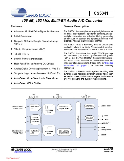
Single-Ended Analog Input
AINR Switch-Cap ADC
High-Pass Filter
Low-Latency Digital Filters
Serial Port
VL 1.8 V to 5 V
Auto-detect MCLK Divider
Master Clock
Slave Mode Auto-detect
The CS5341 is available in a 16-pin TSSOP package for Commercial (-10° to +70° C) and Automotive grades (-40° to +85° C). The CDB5341 Customer Demonstration Board is also available for device evaluation and implementation suggestions. Please refer to “Ordering Information” on page 22 for complete ordering information.
Confidential 05 dB, 192 kHz, Multi-Bit Audio A/D Converter
Features
Advanced Multi-bit Delta-Sigma Architecture 24-bit Conversion Supports All Audio Sample Rates Including
4.1 Single-, Double-, and Quad-Speed Modes ..................................................................................... 15 4.2 Operation as Either a Clock Master or Slave ................................................................................. 15
PMS150C datasheet V001_CN-1
PMS150C系列8位IO类型单片机数据手册第0.01版2016年3月17日Copyright 2016 by PADAUK Technology Co., Ltd., all rights reserved重要声明应广科技保留权利在任何时候变更或终止产品,建议客户在使用或下单前与应广科技或代理商联系以取得最新、最正确的产品信息。
应广科技不担保本产品适用于保障生命安全或紧急安全的应用,应广科技不为此类应用产品承担任何责任。
关键应用产品包括,但不仅限于,可能涉及的潜在风险的死亡,人身伤害,火灾或严重财产损失。
应广科技不承担任何责任来自于因客户的产品设计所造成的任何损失。
在应广科技所保障的规格范围内,客户应设计和验证他们的产品。
为了尽量减少风险,客户设计产品时,应保留适当的产品工作范围安全保障。
PMS150C不适用于交流供电阻容降压或者电源纹波大,EFT要求高的应用,请注意不要将PMS150C用于这种特殊要求的产品中。
提供本文档的中文简体版是为了便于了解,请勿忽视文中英文的部份,因为其中提供有关产品性能以及产品使用的有用信息,应广科技暨代理商对于文中可能存在的差错不承担任何责任,建议参考本档英文版。
目录1. 单片机特点 (7)1.1. 系统功能 (7)1.2. CPU特点 (7)2. 系统概述和方框图 (8)3. 引脚功能说明 (9)4. 器件电气特性 (10)4.1 直流交流电气特性 (10)4.2 工作范围 (11)4.3 IHRC频率与VDD关系曲线图 (12)4.4 ILRC频率与VDD关系曲线图 (12)4.5 IHRC频率与温度关系曲线图(校准到16MHz) (13)4.6 ILRC频率与温度关系曲线图 (13)4.7 工作电流与VDD、系统时钟CLK=IHRC/n曲线图 (14)4.8 工作电流与VDD、系统时钟CLK=ILRC/n曲线图 (14)4.9 引脚上拉电阻曲线图 (15)4.10 引脚输出驱电流(Ioh)与灌电流(Iol) 曲线图 (15)4.11 引脚输出输入高电压与低电压(V IH / V IL) 曲线图 (16)5. 功能概述 (17)5.1程序内存——OTP (17)5.2 开机流程 (17)5.3 数据存储器 – SRAM (18)5.4 振荡器和时钟 (18)5.4.1内部高频振荡器和内部低频振荡 (18)5.4.2芯片校准 (18)5.4.3 IHRC频率校准与系统时钟 (19)5.4.4系统时钟和LVR基准位 (20)5.5 16位定时器 (Timer16) (21)5.6 看门狗定时器 (22)5.7 中断 (22)5.8 省电与掉电 (24)5.8.1省电模式(stopexe) (24)5.8.2掉电模式(stopsys) (25)5.8.3 唤醒 (26)5.9 IO引脚 (27)5.10 复位和LVR (28)5.10.1复位 (28)6. IO 寄存器 (29)6.1 标志寄存器(flag),IO 地址 =0x00 (29)6.2 堆栈指针寄存器(sp),IO地址 =0x02 (29)6.3 时钟控制寄存器(clkmd),IO地址 =0x03 (29)6.4 中断允许寄存器(inten),IO地址 =0x04 (30)6.6 Timer16控制寄存器(t16m),IO地址 =0x06 (30)6.7 外部晶体振荡器控制寄存器(eoscr,只写),IO地址 =0x0a (31)6.8 中断缘选择寄存器 (integs), IO地址 =0x0c (31)6.9 端口A数字输入启用寄存器(padier), IO 地址 =0x0d (31)6.10 端口A数据寄存器(pa),IO地址 =0x10 (31)6.11 端口A控制寄存器(pac),IO地址 =0x11 (31)6.12 端口A上拉控制寄存器(paph),IO地址 =0x12 (31)6.13 杂项寄存器(misc), IO 地址 =0x3b (32)7. 指令 (33)7.1 数据传输类指令 (34)7.2 算术运算类指令 (36)7.3 移位元元运算类指令 (38)7.4 逻辑运算类指令 (39)7.5 位运算类指令 (41)7.6 条件运算类指令 (41)7.7 系统控制类指令 (42)7.8 指令执行周期综述 (44)7.9 指令影响标志的综述 (45)8. 特别注意事项 (46)8.1. 使用IC时 (46)8.1.1. IO使用与设定 (46)8.1.2. 中断 (46)8.1.3. 切换系统时钟 (47)8.1.4. 掉电模式、唤醒以及看门狗 (47)8.1.5. TIMER16溢出时间 (47) (47)8.1.6. LVR8.1.7. 指令 (47)8.1.8. RAM定义限制 (47)8.1.9. 烧录方法 (48)8.2. 使用ICE时 (48)修订历史:修订日期描述初版0.01 2016/3/17PMS150B 和PMS150C 主要差异表PMS150B 与PMS150C 主要差异列举如下:项目 功能PMS150BPMS150C1 ILRC 频率 110KHz@5.0V ,25oC 62KHz@5.0V ,25o C (VDD 变化对ILRC 有影响) 2 LVR 2.8V,2.2V,2.0V 4.0V,3.5V,3.0V,2.75V 2.5V,2.2V,2.0V,1.8V 3 RAM 60 bytes64 bytes 4 PA5口输入模式上拉电阻 没有有5 工作温度0o C ~70o C -20o C ~70o C6省电模式功耗(stopexe ) 40uA@3.3V3 uA@3.3V7 IO 输出电流 17mA/-7mA@5.0V普通模式:14.5mA/-10.5mA@5.0V低驱动模式:5mA/-3.5mA@5.0V 8 看门狗定时器溢时 4096,16384,65536 ILRC 时钟周期8192,16384,65536,262144 ILRC 时钟周期9 唤醒时间 快速模式:1024 T IHRC 普通模式:1024 T ILRC 快速模式:32 T ILRC 普通模式:2048 T ILRC 10 开机时间快速模式:2048 T IHRC 普通模式:1024 T ILRC快速模式:32 T ILRC 普通模式:2048 T ILRC 11系统保留OTP 区 0x3F8~0x3FF(8 word) 0x3F0~0x3FF(16 word)12 ILRC 做系统时钟源 ILRC,ILRC/4 ILRC,ILRC/4,ILRC/16 13支持ICE 类型PDK3S-I-001/002/003, 5S-I-S015S-I-S011. 单片机特点1.1. 系统功能◆时钟模式:内部高频振荡器、内部低频振荡器◆硬件16位定时器◆快速唤醒功能◆ 6 个带输入上拉电阻IO引脚,且做输出时具有可选的电流驱动能力◆1个外部中断输入引脚◆每个引脚都可弹性设定唤醒功能◆8级LVR可选◆工作频率0 ~ 8MHz@VDD≧3V; 0 ~ 4MHz@VDD≧2.2V; 0 ~ 2MHz@VDD≧2.0V;◆工作电压:2.0V ~ 5.5V◆工作温度:-20 o C ~70 o C◆功耗特性:I operating ~ 0.3mA@1MIPS, VDD=3.3VI operating ~ 13uA@ILRC=62KHz, VDD=3.3VI powerdown ~ 0.5uA@VDD=3.3V1.2. CPU特点◆工作模式:单一处理单元的工作模式◆ 1KW OTP程序内存◆ 64字节数据存储器◆提供79条指令◆绝大部分指令都是单周期(1T)指令◆可程序设定的堆栈深度◆所有的数据存储器都可当数据指针(index pointer)◆独立的IO地址以及存储地址方便程序开发2. 系统概述和方框图PMS150C是一个IO类型、完全静态,以OTP为程序存储基础的单片机。
XSeries产品XRC系列远程控制器数据手册说明书

Data Sheet 2101180-ACX RC 6490, X RC 6790, and X RC 6890X Series ProductsRemote Controller omputers (XFC)C ontrollers (XRC)This datasheet focuses on the X RC products, X Ser-ies Remote Controllers (RTUs). Benefits and fea-tures of these particular products include:Automation, control, alarming and data loggingBase IO targeted at low cost automation projects Local display and optional keypadQuick, easy installationFlexible communicationsComprehensive custody quality math and dataExtendable hardware and softwareX RC 6490, X RC 6790, and X RC 68902101180-AC2In addition to the local configuration port, two com-munications ports are supplied with the standard unit. These ports are modular and user se-lectable for RS232 and/orRS485. An additional port may be added using a TFIO Com-munications Module.HARDWARE MODULARITYHardware functionality of X Series devices can be extended in a flexible and simple way by adding modular IO as needed.Totalflow’s TFIO modules are designed to accommo-date low power, harsh environments at economical cost. The system recognizes the module types auto-matically and configures the IO Scanner subsystem accordingly.Supported TFIO Modules Include: • Analog In (8 channel) • Analog Out (4 channel)• Binary (DI, DO, PI-8 channels, software select-able)• RTD (4 channel)• Thermocouple (4 channel)• Valve Control (digital or analog)• Communications (software selectable RS232,485, 422-1 channel)For more detailed information about TFIO modules request information on datasheets 2101105 through 2101112.SOFTWARE MODULARITYA keenly flexible and stable real time environment, this software represents significant modularization through use of object oriented design principles. Totalflow supplied objects (applications) can be in-stantiated in our factory or by you, one or more times on the same device. It is this framework that allows the support for multi-tube measurement.Supported Software applications continually grow, but a sample of standard applications include: • AGA3 orifice meter run • ISO 5167 orifice meter run • VCone meter run• AGA7 rotary/turbine meter run • Real-time Data logger (trending) • Valve Control (Feedback controller) • RAMS (Alarming, Exception Reporting) • Operators (simple custom math / logic) • IEC 61131 (complex math / logic)• Selectable Units (user selectable engineering units)• Display / Keypad Handler • Wedge Meter (water or gas) • IO subsystem Handler • Tank Level Application • Therms master application • Therms slave application•Multiple protocols (Totalflow native low power, Modbus slave (binary/ASCII), Modbus master (binary/ASCII), LevelMaster, Btu 8000/8001, En-ron Modbus, MotorSaver, ABB 267CS/269CS XMV Multivariable, Altronic and others)X SERIES REMOTE CONTROLLER FEATURES• Significant hardening against over-current / tran-sients◊ Positive Temperature Coefficient, resettingfuses and transient protection on ∗ VBATT and SWVBATT Outputs ∗ Each of the Digital Outputs ∗ Battery Charger Input◊ EMI/RFI suppression beads on all I/O points ◊ Protection against reverse polarity wiring ◊ Power supply circuit designed to protectXIMV from hot insertion.• Base IO on RC195 Board◊ 5 Analog Inputs◊ 4 Digital Inputs (2 can be used as hi-speedPIs)◊ 4 Digital Outputs ◊ Battery Voltage ◊ Charger Voltage• Low power design operating as low as 8 ma(<100 mW)• Aluminum enclosure, powder coated• Flexible accommodation of communicationshardware• Cost effective communications kits • Stable time base (accurate integration) • Rechargeable, lead acid batteries • Solar, AC or DC charging options•Dual level security code data protectionX RC 6490, X RC 6790, and X RC 68902101180-AC3•Custody transfer applications◊ Monitors user limits for detection, and report-ing of abnormal conditions◊ Defaults to 45 Days of hourly and daily data.User configurable.◊ Defaults to 200 Events. User configurable. ◊ Complies with API 21.1 standard for custodytransfer devices◊ Flow and energy calculations per AGA3-85,AGA3-92, AGA-7, and AGA-5◊ Super compressibility calculations per NX-19or AGA8-92 Gross or Detail◊ Flow retention during user transducer calibra-tion◊ Selectable 3 or 5 point user calibration ofAnalog Ins◊ Zero flow detection• Class I, Division 2 Groups C and D, CSA C/US Hazardous Area Classifications (ATEX Zone 2 pending)• Real time clock that keeps running on lithium bat-tery• Advanced embedded data logger • Programmable alarm filtering • Exception reporting capability• Multiple protocol options including Totalflow packet protocol, various modbus protocols and others• User programmable modbus register maps • User programmable math and logic sequences • IEC 61131 Capability•Valve Control and Nominations CapabilityABCDA. RC195 BoardB. Communications Equipment CompartmentC. Battery CompartmentD. TFIO ModulesDimensions Width 12.756 in. (324.00 mm) 14.920 in. (379.53 mm) 20.090 in. (510.29 mm)Height 17.230 in. (437.64 mm) 21.845 in. (554.86 mm) 28.910 in. (734.32 mm)Depth 10.269 in. (260.83 mm) 13.710 in. (348.23 mm) 15.520 in. (394.21 mm)Installed Depth Pipe Mount 1.584 in. (294.23 mm) 14.56 in. (369.82 mm) 16.82 in. (427.23 mm)Wall Mount 11.019 in. (279.88 mm) 14.00 in. (355.60 mm) 16.26 in. (413.00 mm)Weight (w/o Battery) Approx. 15 lbs. (6.8 kg) Approx. 29 lbs. (13.1 kg) Approx. 45 lbs. (20.6 kg)Max IO Modules 3 6 14 Max Battery Capacity 26AH 42AH 140AHCertification CSA C/US Class 1, Division 2, Groups C & D hazardous area classification. (ATEX Zone 2 pending)Mounting Wall, pipe, or direct Operating Temperature(ambient)-40°F to 140°F (-40°C to 60°C) Humidity 0 - 95% non-condensingEMC Requirements EMMISSIONS:European Regions:EN55022 Class A Emissions (Radiated & Conducted) North America Regions:CFR 47, Part 15, Subpart B, Class A, FCC Emissions ICES-003 Issue 2, Rev. 1, Class A ITE Emissions IMMUNITY: European Regions:EN50082-1:98 ImmunityEN61000-4-2:95, ESD, + 8 kV Air, + 4 kV ContactEN61000-4-3:95 RF Immunity, 10 V/mEN61000-4-4:95 EFT, 1 kVEN61000-4-5:95 Surge; 1kV line to line, 2kV line to earth EN61000-4-6:95 Conducted Susceptibility, 3 VrmsEN610004-8:93 Power Frequency Magnetic Field 3 A/m EN610004-11:94 Voltage DIP and interrupt4Power and Productivity for a Better World. ™ /totalflowABB Inc.Totalflow Products 7051 Industrial Blvd. Bartlesville, OK 74006 Tel: (918) 338-4888 Fax: (918) 338-4699 (800) 442-3097 ABB Inc.Totalflow Products433 Northpark Central Dr., Ste. 100Houston, TX 77073Tel: (281) 869-5212Fax: (281) 869-5203(800) 442-3097For more information,please contact yourlocal ABB Totalflowrepresentative or visitour website.Power Nominal 12 VDC battery Charger Solar or 16-18 VDCMemory • Data stored in 512K SRAM. (lithium battery backup) • Applications programs stored in 512K Flash.• Flash loader stored in 512K PROM• Registry and Configuration files stored in 32K E2PROMComm Ports • 1 - dedicated – PCCU (Local Configuration Port) • 2 - RS232 or RS485 (via board insertion modules)LCD Interface Dedicated interface for 2 X 24 Liquid Crystal Display (LCD)Keypad Interface Dedicated interface for optional ABB supplied keypadIO Expansion I2C Bus Interface for TFIO ModulesSecurity Switch Dual-Level Security Switch On-BoardTime Base Stability ± 7.5 ppm (parts per million)IO Scan Rate 1 Time per SecondAnalog Inputs 5 single-ended channels, 0-10VdcAnalog-to-Digital Resolution 18 Bit maximum resolution (0.00038% FS)16 Bit nominal resolution (.0.0015%FS)Digital Inputs 4 inputs configurable as active or passive with optional software de-bounce Pulse Inputs 2 of the 4 digital inputs can be used as pulse inputs (up to 20KHz)Digital Outputs 4 open channel FET transistor switches。
videotec 2015 产品目录中文版说明书

中文产品说明书 2015 CCTV 产品DOCCTZH1507产品说明书 2015 / 修订号 1507所示的全部摄像机和镜头只用于说明, 并非随产品提供 ("ULISSE", "ULISSE COMPACT", "NXPTZ/NXPTZT", "MAXIMUS MPX/MPXT", "MAXIMUS MHX/MHXT", "NTC" 除外)。
如要获取更多信息, 请浏览产品页中的技术数据表。
未经 Videotec S.p.A书面许可, 不得将本文的全部或部分进行复制、修改或记录于文件系统, 以任何形式或者任何电子、机械或记录方式传输。
本文包含的技术规格可能会变更: Videotec S.p.A.保留变更而不事先通知的权利。
技术规格如有变更, 恕不另行通知。
重量和尺寸只作说明用途。
二月 2015. 所有旧版目录均废除。
VIDEOTEC: 辉煌的历史在近三十年,在視頻監控行業的活動,我們設計,創建並獲得專利的眾多產品監測所有類型的外部環境。
今天,我們的公司是一個最受人尊敬的供應商在同行業中,得益於我們的創新,我們的發展CCTV解決方案,保證安全性和可靠性。
遍布全球的销售和技术支持VIDEOTEC的销售和生产总部位于意大利东北部,占地1.3万平方米,另外在法国,美国,加拿大以及亚太地区设立了分部. 迄今为止,VIDEOTEC已经在全球建立了超过100家分销商的营销网络,总的来说,即使面对安防领域最复杂的行业要求,我们也能提供一整套完整的产品选型以及解决方案.产品适合于各种行业我们产品的适用范围非常广泛:从政府部门到国有或私有企业,商业部门,银行以及监狱的视频监控.在这些领域之外还有工业上的应用,比如在高温环境下或特殊的气候环境下,交通控制系统下,城市检测以及海滩和边境系统下,防止某些潜在的爆炸性事件的发生.无与伦比的品质每个VIDEOTEC的解决方案都是由我们的专业人员与国际尖端大学以及研究机构合作后的结果.这种操作模式允许我们作为行业先锋,在实验中用专业的技术以及先进的材料来创造出绝对创新的产品以及解决方案.易安装易维护我们的产品的性能是完美的,并且它的易于安装以及持久稳定性更保证了我门著重于设计的产品理念,这也是我们公司的独特标志,是我们对产品的卓越品质的一份保证.3香港內容9云台摄像机单元防爆云台摄像机单元不锈钢云台摄像机29摄像机外壳隐蔽监视摄像机防护罩防破坏摄像机防护罩防爆摄像机及其防护罩不锈钢摄像机及其防护罩447云台马达不锈钢云台遥测防爆解码器53红外/白光照明灯57视频内容分析63控制键盘矩陣视频分配器67视频传输69摄像机支架5OIL AND GAS市場INDUSTRY PLANTSTERMINALSDRILLING RIGS OIL AND GAS TANKERS PIPELINESOFFSHORE MARINEONSHORE - PERIMETER APPLICATIONSONSHORE - INTERNALAPPLICATIONS OIL AND GAS PLATFORMS67INFRASTRUCTURES AND TRANSPORTATIONCITY SURVEILLANCEBRIDGESPARKING LOTSUNDERGROUNDSAIRPORTSRAILWAYS AND STATIONSHIGHWAYSSTADIUMSTUNNELS8规格如有改变,恕不另行通知。
GPS15L产品说明书

GPS 15L产品说明书1、产品简介1.1产品综述GPS 15H &15L是GARMIN公司为广谱的OEM(原始设备制造)系统应用而设计的最新一代的GPS传感器板的一部分。
基于其它GARMIN的12通道GPS 接收机的成熟技术,GPS 15H & 15L在同一时间可以跟踪多大12个卫星,与此同时还提供快速的首次时间定位,一秒钟导航更新以及低功耗。
GPS 15H & 15L 还可以提供FAA的差分GPS广域增强系统的性能。
他们广泛的性能需要对陆地导航的敏感性,授时的精确性以及对高性能飞机的动力学要求。
这些GPS的设计采用的是最新的技术和高级电路集成,以达到更好的运行效果并且最大限度的减小空间和功率需求。
所有关键技术都是由GARMIN公司设计和指导的,以保证产品的质量和GPS的性能,这些关键技术包括射频/中频接收机硬件和数字基带。
硬件的性能结合软件的智能使得GPS 15H &15L更容易整合和使用。
一个完整的GPS接收器还需要由OEM或者系统集成商提供的最低限度的附加组件。
GPS的最小系统包括一个电源、一个有效的GPS天线以及对GPS卫星的清晰视界。
系统可以通过两个RS-232兼容接收串口和一个发送串口来与GPS 15H & 15L进行通信。
GPS 15H &15L内部的闪存可以允许GPS保存一些关键数据,如:卫星轨道参数,最后出现的位置、日期和时间等。
应用设计者可自行在终端用户接口上接上如键盘和显示器之类的硬件。
1.2产品特征•12通道GPS接收机跟踪和使用12个卫星通道以保证快速精确定位,而且保证功耗很低。
•差分DGPS采用实时广域增强系统和RTCM修正法可以使精度达到3~5米。
•位置精度(见1.5.3.4)。
•紧凑、坚固的设计理念为应用提供了最少的空间。
可以远程的安装在一个偏僻的位置。
接收机状态信息可以直接显示在一个chartplotter或者个人电脑上。
XIRIA Plus Compact和环保版电子环形主机的说明手册说明书

AutomotiveAerospaceElectricalTruckHydraulics1Powering business worldwideNext generation transportationEaton is driving the development of newtechnologies –from hybriddrivetrains and emission control systems to advanced engine components –that reduce fuel consumption and emissions in trucks and cars.Higher expectationsWe continue to expand our aerospace solutions andservices to meet the needs of new aviation platforms,including the high-flying light jet and very light jet markets.Building on our strengths Our hydraulics businesscombines localised service and support with an innovative portfolio of fluid powersolutions to answer the needs of global infrastructure projects,including locks,canals and dams.Powering Greener Buildings and BusinessesEaton’s Electrical Group is a leading provider of powerquality,distribution and control solutions that increase energy efficiency and improve power quality,safety and reliability.Our solutions offer a growing portfolio of “green”products and services,such as energy audits and real-time energy consumption monitoring.Eaton’s Uninterruptible Power Supplies (UPS),variable-speed drives and lighting controls help conserve energy and increase efficiency.Eaton delivers the power inside hundreds of products that are answering the demands of today’s fast changing world.We help our customers worldwide manage the power they need for buildings,aircraft,trucks,cars,machinery and entire businesses.And we do it in a way that consumes fewer resources.Eaton’s range ofSF6free switchgearfor Medium VoltageEaton Corporation is a worldwide leader in thedesign, manufacture, and sale of safe, reliableand high-performance medium voltage powerdistribution equipment in accordance with IEC,ANSI and GB / DL standardsComplete Global Medium Voltage Switchgear SolutionsEaton,a premier leader in designing and manufacturing powerdistribution and protection equipment in the electrical industry,offers a comprehensive range of medium voltage(MV)solutionsto meet the needs of virtually every application.From productsthat feature cutting-edge design that allow for easy access,maintenance and space savings,to arc-resistant products thatenhance safety,Eaton’s medium voltage solutions provide avariety of products for every need.Additionally,Eaton’s globalservice network provides maximum customer support in allregions of the world.As one of the few completely vertically integrated and diversifiedindustrial manufacturers in the world,Eaton designs not only MVassemblies,but also the key components that comprise the MVsolutions–from steel housing and circuit breaker compartmentsto vacuum interrupters,circuit breakers,bus systems and fuses.Eaton’s MV heritage,strengthened by acquisitions such asWestinghouse DCBU,Cutler Hammer,MEM and Holec,hasresulted in breakthrough MV technologies and numerousinternational patents over the years.Part of Eaton’s complete electrical PowerChain Solutions–which help businesses minimize risks while realizing greaterreliability,cost efficiencies,capital utilization and safety–Eaton’s medium voltage equipment meets all applicablestandards and certifications such as IEC,NEMA/ANSI,GB / DL,UL,IEEE,KEMA and CSA.When it comes to medium voltage solutions,you can trust theone name with a long history of proven performance:Eaton.3XIRIA Plus is the name of Eaton's new solid insulated RMU for smart grid applications. The system is characterised by its high level of operational safety and is suitable for applications up to 12kV.The XIRIA Plus RMU is designedaround Eaton's proven vacuuminterrupters, which require nomaintenance and are certified for10,000 operation cycles.All live parts in the available panels aresingle pole insulated. The usedmaterials are shaped specifically toprovide optimum insulation combinedwith excellent thermal characteristics.In addition, the insulation is configuredto provide effective control over electricfields around the used components,thereby minimizing any risk of internalarcing.Within the XIRIA Plus panels both theprimary parts and the mechanisms arehoused in a fully enclosed housingwhich protects the whole systemagainst environmental influences. Theuse of vacuum interrupters and solidinsulation means that the XIRIA Plus isenvironmentally friendly. Thesetechnologies ensure that this system isa conservational alternative toswitchgear systems using SulfurHexafluoride (SF6) gas for insulation. Thecost of ownership is also significantlyreduced, as no regular testing of gaspressure or other routine maintenance isneeded and there is no high end-of-lifecost associated with ultimately disposingof the equipment.With a compact design and a provisionfor cable connection from the front, theXIRIA Plus system is economical in itsuse of valuable floor space, and easy toaccommodate in even the most restrict-ed environments.When it comes to the safety of theoperating personnel the XIRIA Plusdesign leaves nothing to chance.All parts are fully enclosed by an internalarc tested safe metal housing.The panels in the system are providedwith direct visible indication of theintegrated earthing and ON/OFF-positionby means of inspection windows in thefront.XIRIA PlusSolid insulated RMU for smart grid application4XIRIA PlusSafe reliable and efficient solutions for all applications in the medium voltage secondary distribution network.Smart grid readinessDesigned to integrate solutions for sensing, monitoring and remote control for feeder automation and load management purposes.Safe in use•Visible isolation by means of inspection windows in the front •Compartments protected against penetration of objects •Capacitive voltage detection system for verification of safe isolation from supply•Logical mechanical and electrical interlocks prevent misoperationEnvironmentally friendly•Minimized number of components•Environmental-friendly design with respect to the materials used•No use of SF6-gas for switching and insulation•Minimal number of transition points in primary design enable low energy loss during operation•Only re-usable and / or recyclable materials usedUser friendly•Cable connection and user interfaces for operation on the same front side of the panel•Ergonomic cable connection height• A customized low voltage compartment is optional •Clear and simple straightforward operation panelsLow total cost of ownershipLow initial costs due to:•Panels with only 350mm or 450mm width depending on function•Cable connection from the front / wall standing arrangement No costs during service due to:•Robust design with minimum number of parts (routine tested in factory)•Long-life solid insulated components as insulation medium •Maintenance free vacuum circuit-breaker and loadbreak switch •Primary parts and mechanism installed in a fully sealed for life enclosed housing•No SF6 pressure checksLow end of life disposal cost due to:•Vacuum switching technology•Solid insulation with air as isolating medium •Recycling or re-use of materialsOperation•Complete design certified in accordance with GB standards • Arc fault tested according GB 3906-2006• Quality assurance in accordance with ISO 9001• Single pole insulated primary parts within one compartment • Primary parts and mechanism in sealed for life fully enclosed housing• Configurations up to 6 functions in one tank• Field extensible for projectsrequiring more than six functions3-position disconnector All panels are equipped with a disconnector positioned in the same sealed for life enclosure as the circuit-breaker. The disconnector consists of three shafts connected to the busbars or earthing points. Since it is mechanically interlocked the disconnector can only be operated when the circuit breaker is in the open position.•Manual-operated switch with 3-position (service / isolated / earthed)•Maintenance free•Housed in sealed for life enclosure•Auxiliary contacts for service / isolated / earthed•Position indication by means of inspection windows and mechanical indicators•Mechanically interlocked with the vacuum circuit-breaker3-All entocan5Main constructionVacuum technology features•Eaton has an unsurpassed leadership in vacuum technology supported by a strong heritage of innovation from companies such as Westinghouse and Holec•Pioneers in vacuum technology for over 90 years. First vacuum interrupter supplied at 15kV-12kA in 1967•Eaton was the first one to develop and patent copper-chromium alloy content for contacts and center shields•Our vacuum interrupters for contactor applications can perform up to 2.5 million mechanical operations•More than 5 million units delivered worldwide, operating safely and reliably in all types of networks, medium voltage applications and environments•High end certified supplier to almost all major electrical manufacturers worldwideSolid insulation system•More than 60 years experience in solid insulation technology with hundreds ofthousands of functions successfully operating worldwide in all kinds of environment without any ageing concern•Full encapsulation capability in the 1990’s •High thermal conductivity •High electrical resistivity •Low moisture absorption•High creepage current resistance •High mechanical strength•Optimized electrical field control•Fully insulated busbars to prevent any phase to phase and phases to earth faults •Optional extensible busbarsVisible isolation by means of inspection windows in the frontWhen carrying out operational actions and work on the cables, it is vital to have unambiguous status indications. When it comes to the safety of operating personnel Eaton leaves nothing to chance. That is why the XIRIA Plus design is fitted with directly visible isolation by means of inspection windows in the front which makes the isolating distance between the cable and busbar system directly visible. A visible, shortcircuit proof earthing can take place via the load-break switch orcircuit-breaker.Capacitive voltage detection system for verification of safe isolation from supplyEach panel type within the XIRIA Plus family is equipped with a standard three phase Voltage Detection System for voltage testing. The VDS shows the operator if the panel is isolated from supply or not. Logical mechanical and electrical interlocks prevent incorrect operationWithin the XIRIA Plus design misoperation by an operator is prevented by using different interlocks. The interlocks are mechanical and electrical. For example electrical and mechanical interlocks prevent operation of the change-over switch when the circuit-breaker is switched on. All mechanical interlocks are constructed in such a way that they directly block the mechanism. Switching to service position is only possible with closed cable compartmentAs standard, the door of the cable compartment can only be opened when thecircuit-breaker is in the earthed position. After the door isremoved it is possible to switchoff the circuit-breaker for cabletesting. Switching on to serviceposition is only possible withthe door positioned back again.Compartments protectedagainst penetration of objectsWithin the XIRIA Plus design itis not possible to accidentallypenetrate the switchgear bypart of a body or a tool.All high voltage compartmentsare designed according to IP65degree.Smooth contemporary designAll compartments of the XIRIAPlus panels are designed insuch a way that the system issafe to touch from the outside.By using a smooth and smartdesign it is not possible for theoperator to injure himself bymoving parts or by parts thatstick out of the switchgearwhen moving in front of theswitchgear.Routine testsVarious prescribed routine testsare carried out during theproduction of the switchgear.To assure quality, all processesare in accordance with ISO9001. This means that at everystage of production thecomponents, circuit-breakersand current transformers areinspected for correctfunctionality. When the entireinstallation has beenassembled, a thorough visualinspection is carried out,together with mechanical,functional and electrical checks.Philosophy on internal arcsEaton always puts extra focuson creating safe switchgear foroperators at all times. One ofthe biggest potential threats tooperators is an internal arc inswitchgear.Engineers therefore did every -thing necessary in design andconstruction to prevent internalarcs.Eaton supports the philosophythat it is best to avoid internalarcs than to cure, in line withthe relevant standardGB3906-2006. Within the XIRIAPlus design a double preventionphilosophy is used. Firstly, thedesign is constructed in such away that an internal arc isprevented. In the unlikely casethat an internal arc could occur,the XIRIA Plus is equipped toprovide maximum safety to theoperator, and to control andminimise damage to the rest ofthe switchgear and room.Safe in useThe XIRIA Plus design contains some special features that guarantee theoperator to work safely with the different panel types.What you see is what youget!67One of the key strategic initiatives of Eaton is to provide environ-mentally friendly products. Eaton achieves this by looking at the total product chain, from design to dismantling and recycling.The optimal situation is that for each phase there is no damageto the environment and at the end, all materials can be re-used again in the same product (the Cradle-to-Cradle principle). The product chain can be divided into four main blocks. These blocks are the design (materials used) of the product, the assemblyof the product, the usage phase of the product and finally the dismantling of the product.Environmentally friendlyLike all Eaton medium voltage switchgear,XIRIA Plus is designed to be an environmentally friendly product throughout the whole value chain.With respect to the design of switchgear,the vision "the less number of components the better"applies.This because every part must be manu -factured and therefore impacts on the environment.Next,applies the affect of different materials on the environment. Use of minimized number of componentsXIRIA Plus is designed to use the minimum of materials and resources,without affecting the strength of the system. For example,Eaton reduced the number of components dramatically,compared to conventional switchgear,by using a simple spring charging mechanism and integrated compartments.This also ensures straight forwardassembly with low labor cost.Materials with no/lessimpact on the environment Eaton selects materials with care.It is essential that they are safe for personnel and the environment -not just during use,but at the end of service life too.Within XIRIA Plus a combination of solid (cast resin)insulation and air as insulation medium is used.The solid insulationtechnology,in combination with electrical field calculations,provides a very compact,environmentally friendly design for the switchgear.As theswitching medium,vacuum technology is used within the interrupters of the XIRIA Plus circuit-breakers.XIRIA Plus can be completely recycled at the end of its life.No use of SF 6gas for insulation or switching Emissions switchgear contribute of SF 6-gas from significantly to the threat of the greenhouse effect and associated climate change.SF 6is on the list of greenhouse gasses in the Kyoto protocol.SF 6is the most potent of the six main greenhouse gasses,with a Global Warming Potential (GWP)of 23,000.Eaton made a fundamental choice not to use SF as 6a switching and insulation medium for medium voltage equipment. The main reason for not using anySF 6in medium voltage equip -ment was the complexity of the treatment required for the toxicity of the gasses that have been in contact with an arc,and the need for additional safety measures when used in public locations such asresidential areas and shopping centers.Besides the energy sources,special focus was placed on the efficient use of material during assembly.For example,sheet steel plates are cut with as little waste material as possible.Residual material is used within other product components.Environmentally friendly designEfficient use of materialsTo prevent energy loss by the system itself,XIRIA Plus uses a minimum number of primary change-over points.All the available change-over points use optimal surface contacts and by this,prevent extra energy losses over these points.Minimal energy loss during operationDuring dismantling,XIRIA Plus switchgear is demounted into parts and thereafter categorized per material.Next the parts will be recycled or re-used.Because XIRIA uses no SF 6,there is no loss of this gas during dismantling of the switchgear.Re-use or recycling of materialsBecause XIRIA Plus is designed for a lifetime of at least 30years,the system needs no energy usage for maintenance activities during this long period.Due to the green insulation and switching technology,there is also no leakage of the SF 6-gas during its lifetime and no need for extra maintenance activities on SF 6pressure checks.No service checks on site8Features and benefitsThe benefit of a sealed for life tankA “sealed for life” steel enclosure contains all primary parts and driving mechanisms • Maintenance free • Internal arc proofThe benefit of a compact design•Minimal floor space •Low building costs •Easy to install•Up to 6 feeders in one tankExtensibility• Safe and reliable field extensible solution for projects requiring more than six functions •Epoxy extensible busbar bushing •Single phase insulating•Self-pluggable contacts design •Easy to install on siteProduct range for highest flexibility in use•Flexible combination to build configurations up to 6 functions in one tank.•Any combination of load break switches and circuit-breakers can be placed in a 2- 3- 4- 5 or 6 panel unit.Smart grid readinessAutomation upgrading •Remote close/open•Auxiliary contacts for each position local or remote indications•Measuring CT and current signal Option•Trip indicator with auxiliary contacts •Fault indicator •Current meterLoad break switch “C”Fuse-switch combination“F”Circuit breaker “T”Bus coupler “B”Metering panel “M1”Direct connection“D”Busbar PT panel “M2”Disconnector PT panel “Cv”Cable connectionPT panel “PT”OptionwConfiguration information LBS function, type C panelStandard630A vacuum LBSThree-position disconnector Voltage indicator630A bushing Options Motor operation Fault indicator Current meterType D panelStandardVoltage indicator630A bushingPadlock for cable compartment cover Options Fault indicator Current meter910Fuse-switch function, type F panelThe guide for fuse selectionGeneral type XRN-T/12Fuse selection and transformer application Rated voltage (12kV)Preferred type SDLDJ SF(K)LDJRated voltage (kV)1212Rated fuse current (A)3.15、 6.3、 7.5、 10、 16、 20、 25、 31.5、 4050、 63、 80100、 125Transformer rated capacity (kVA)Fuse rated current (A)Length A (mm)292292292Diameter D (mm)516676The fuse dimensionStandard 630A vacuum LBS Three-position disconnector Voltage indicator Type C bushing Fuse blown indicationOptions Motor operation Fault indicator Current meter Fuse Type A bushingFuse striker:Medium type (according GB15166.2, alternating current switch-fuse combinations).50100125160200250315400500630800100012506.31016162025324050638010012511CB function, type T panelTLF protection for circuit breaker function design• Time limit fuse “TLF” protection is an alternativefor the standard electronic protection relay.• It ensures tripping of the circuit-breaker through a patented electronic circuit in the event of phase short-circuit and earth fault currents • High reliability • Compact design• Fully enclosed housing• Easy accessible fuses on the front • Easy selection of current setting• Compliance with ENA specification 12-6 issue 1:1973• Fully certifiedProtection CT Type WIC1-WE2WIC1-W2WIC1-W3Primary current scope 16-56A 16-56A 32-112AType WIC1-W4WIC1-W5WIC1-W6Primary current scope 64-224A 128-448A 256-896AOptionsProtection relay and CT WIC1-2PE (Standard)WIC1-1PE (Optional)Motor operation Fault indicator Current meterWI1-SZ5 trip indicator with auxiliary switches WIC1-PC2 adapter for relay settingStandard630A vacuum CBThree Voltage indicator 630A bushingWI1-position disconnector -SZ4 trip indicatorType B panel Type M1 panelStandardTwo 0.2s single phase metering PTs Two 0.2s single phase metering CTs The 500mm height low voltage compartment OptionsMoisture sensor and heater Electrical locking of energized cable compartment cover Voltage meterA A A StandardVoltage indicator630A LBS630A bushingThree-position disconnectorOptions630A CBMotor operation1213GeneralRated voltageImpulse withstand voltagePower frequency withstand voltage Rated frequencyInternal arc classification (IAC)Degree of protection in serviceDegree of protection with doors/covers open Ambient air temperature range Busbar systemRated normal currentRated short-time withstand current Rated peak withstand current Load break switches Rated normal currentRated short-circuit making current Rated short-time withstand current Rated cable charging breaking current Mechanical endurance classMechanical endurance class as 3-position disconnector Electrical endurance class Circuit-breakersRated normal current Rated breaking currentRated short-circuit making currentRated capacitive switching current class Rated cable charging breaking current Mechanical endurance classMechanical endurance class as 3-position disconnector Electrical endurance classRated short-time withstand current Mechanism type Fuse-switch panel Rated normal currentMax. rated current of the optional fuse Rated breaking currentRated short-circuit making current Rated transfer currentFor others, please contact local Eaton sales representative.ItemXIRIA Plus ratingskV kV kV-1m Hz kA-s°C A kA-s kA A kA kA-s AA kA kA AkA-sA A kA kA ARatings1295 (phase to phase/earth), 110 (Isolation gap)42 (phase to phase/earth), 48 (Isolation gap)50AFLR 20-1IP4X IP2X -25 - +4063020-4, 25-250, 6363050, 6320-4, 25-231.5M2 10000 x M1 3000 x E2 100 x6302050C231.5M2 10000 x M1 3000 x E220-4O - 180S - CO - 180S - CO 100125501253150XIRIA Plus designed to GB standardsXIRIA Plus compiles with the following standards:GB/T 11022-2011 Common specifications for high-voltage switchgear and controlgearGB 3804-2004 High voltage alternating-current switches for rated voltages above 3.6kV and up to and including 40.5kVGB 311.1-1997 Insulation co-ordination for high voltage transmission and distribution equipmentGB 1985-2004 High-voltage alternating-current disconnectors and earthing switchesGB 3906-2006 Alternating-current metal-enclosed switchgear and controlgear for rated voltages above 3.6 kV and up to and including 40.5 kV GB 1984-2003 High-voltage alternating-current circuit breakersGB 16926-2009 High-voltage alternating current switch-fuse combinations14XIRIA Plus dimensionType C panel dimensionType F panel dimensionType T panel dimensionMetering panel and extension dimension (C+M+F)Example for combination dimension Width Depth Height=25mm+350mm+450nn+350mm+25mm =1200mm =720mm =1400mmCFT block type=35mm+420mm+750mm+500mm+35mm =1740mm =720mm=1400mm(M1=1900mm)1400168635720351400298420(Extensible type )635720350(Block type )420(Extensible type )350(Block type )351400148500(Extensible type )370720750500420140019003535450(Block type )2515CFC floor planCable type :3X1 35-630MM2Cable cone type :C630A C (Load-break switch)Cable type :3X1 16-95MM2Cone type :A200AF (fuse combination unit)Pressure relief16CTC floor planPressure reliefCable type :3X1 35-630MM2Cable cone type :C630A C (Load-break switch)Cable type :3X1 35-630MM2Cable cone type :C630A T (Circuit break)17Electrical powermanagement by EatonFoundation for successElectrical power.The most significant and pervasive energy source on earth. It runs businesses, fuels innovations and keeps the lights on.When the power system is not designed or managed properly, it compromises success, resulting in lower productivity and increased costs.Eaton takes the complexity out of power management with industry-leading innovation, expert services and holistic solutions.And our customers realize powerful benefits: improved reliability,increased efficiency and enhancedsafety.Customer criticalIf it’s critical to our customers,it’s critical to us.In fact,we view it all as mission critical.ExpertiseWith unparalleled knowledge of power management across industries,we provide the know-how for every application.SupportOur people makethe difference.Support is not just an extra benefit;it’s at the heart of how we do business.For energy challenges big and small, if it matters to you, it matters to us. Our missionis to ensure your success, however you define it.++全球商业动力之源提供动力。
PCS-915C_X_说明书_国内中文_标准版_X_R1.01_(ZL_YJBH5303.1112)
电话:025-87178185、传真:025-8718208
我们保留在不事先通知的情况下进行技术改进的权利。
电子信箱:nr_techsupport@
南京南瑞继保电气有限公司
公司地址:中国南京江宁区苏源大道 69 号 邮编 211102 公司网址:
印刷电路板 在装置带电时,不允许插入或拔出印刷电路板,否则可能导致装置不正确动作。
外部回路 当把装置输出的接点连接到外部回路时,须仔细检查所用的外部电源电压,以防止所连接的回
路过热。 连接电缆
仔细处理连接的电缆避免施加过大的外力。
版权声明
版本: R1.01 P/N: ZL_YJBH5303.1112
特别注意,一些通用的工作于高压带电设备的工作规则必须遵守。如果不遵守可能导致严重的 人身伤亡或设备损坏。
危险!
在一次系统带电运行时,绝对不允许将与装置连接的电流互感器二次开路。该回路开路可能会 产生极端危险的高压。
警告!
曝露端子 在装置带电时不要触碰曝露的端子等,因为可能会产生危险的高电压。
残余电压
PCS-915C 母线保护装置
说明书
PCS-915C 母线保护装置
前言
使用产品前,请仔细阅读本章节!
本章叙述了使用产品前的安全预防建议。在安装和使用时,本章内容必须全部阅读且充分理解。 忽略说明书中相关警示说明,因不当操作造成的任何损害,本公司不承担相应负责。
在对本装置做任何操作前,相关专业人员必须仔细阅读本说明书,熟悉操作相关内容。 操作指导及警告
ii
南京南瑞继保电气有限公司
PCS-915C 母线保护装置
目录
前言 .............................................................................................................................................i 目录 ...........................................................................................................................................iii 第 1 章 概述..............................................................................................................................1
美国蜜糖电子微开关V15系列产品说明书

V15T16-EZ100A03V15T16-EZ100A03V15T16-EZ100A05V15T16-EZ100-K V15H16-CZ200V15H16-CZ300A0V15H16-CZ300A0V15H22-CZ100A0V15T16-CZ100V15T16-EZ100A02MICRO SWITCH Standard Basic SwitchesV15 SeriesDESCRIPTIONHoneywell’s MICRO SWITCH V-Basic Standard Switch, V15 Series is an electromechanical switch designed to provide outstanding value in a reliable global package. This switch is often ideal for “low-cost-of-failure” applications, where the cost is minimal to replace or service any failure related to the switch. With a wide variety of operating forces, andamperage ratings, the V15 is designed for numerous types of applications.Available in both pin plunger and levered styles, the V15 Series also offers a multitude of termination styles to fit almost any application.VALUE TO CUSTOMERS• Wide choice of electrical ratings: 0.1 A, 5 A, 10 A, 16 A, 22 A, 26 A• Certified for global use: UL/cUL, ENEC, CQC• Available with pin plungers or integral levers to meet multiple application and equipment requirements DIFFERENTIATION• Choice of actuation, termination, and operatingcharacteristics that can allow for flexibility in numerous types of applications• With a broad current capacity, one switch package can control a wide range of electrical loadsFEATURES• Broad range of electrical loads: 0.1 A, 5 A, 10 A, 16 A, 22 A, 26 A• Long service life: over one million mechanical operations • Gold contacts are also available for controlling logic level/low energy circuits• World-wide package size acceptance• UL/CSA, cUL, ENEC, and CQC approvals• Variants with cadmium-free contacts available POTENTIAL APPLICATIONS • Appliances • Furnaces• Gaming machines • Ice makers • Power washers • Vending machinesPORTFOLIOHoneywell offers a broad range of MICRO SWITCH basic switches including large, V-Basic, miniature, watertight, and special application switches.Sensing and Internet of Things004945Issue 10MICRO SWITCH Standard Basic Switches, V15 Seriesmax. inductive value (Amps)• GPA = General Purpose Amps (Inductive Load,75 % to 80 % power factor)• VL = Lamp Load2 Sensing and Internet of Things 3MICRO SWITCH Standard Basic Switches, V15 SeriesV15S05 PRODUCT NOMENCLATUREV15Switch TypeTemperatureGradeSLeverPositionElectrical Rating05V15 Series Standard Basic SwitchTerminal TypeCircuit Code—ZAOperating Force(at pin plunger max)200Mounting HolesKALever Type06Special DesignatorC—Housing Type1V15T10 PRODUCT NOMENCLATUREV15Switch TypeTemperatureGradeTLever PositionElectrical Rating10V15 Series Standard Basic SwitchTerminal TypeCircuit Code—ZAOperating Force(at pin plunger max)200Mounting HolesKALever Type06A special designator letter is used only when there is a special modificationto the switch.Review Product Specification to determine the exact differences. Below is an example.Special DesignatorC—Housing Type1V15H16/T16/T22/H22/T26 PRODUCT NOMENCLATUREV15Switch TypeTemperatureGradeHLever PositionElectrical Rating16V15 Series Standard Basic SwitchTerminal TypeCircuit Code—ZAOperating Force(at pin plunger max)200Mounting HolesKALever Type06Special DesignatorC—Housing Type1MICRO SWITCH Standard Basic Switches, V15 SeriesPinPlunger4 MICRO SWITCH Standard Basic Switches, V15 SeriesShortStraightLeverStandardStraightLeverSensing and Internet of Things 5MICRO SWITCH Standard Basic Switches, V15 SeriesLongStraightLeverSimulatedRoller6 MICRO SWITCH Standard Basic Switches, V15 SeriesShortRollerLeverSensing and Internet of Things 7MICRO SWITCH Standard Basic Switches, V15 SeriesRollerLever8 Sensing and Internet of Things 9MICRO SWITCH Standard Basic Switches, V15 SeriesMOUNTING DIMENSIONSFigure 1. V15 Series Standard Switch DimensionsFigure 2. V15 Series Metric Mounting Hole Dimensions for Ø 3 mm pins or screwsMetric mounting for Ø 3 mm pins or screws Ø 3,10 mm +0,10 mm/-0,05 mm 10,3 m m ±0,1 m m Ø 0.12 in +0.004 in/-0.002 in mounting holeFigure 3. V15 Series USA Mounting Hole Dimensions for #4 screws US mounting for #4 screws - K DesignatorØ 2,90 mm +0,10 mm/-0,05 mm10,3 m m ±0,1 m m Ø 0.11 in +0.004 in/-0.002 in mounting holeFigure 4. V15 Series Housing Dimensions10 Sensing and Internet of Things 1112 STANDARD LEVER OPTIONS • DIMENSIONSFigure 19. V15 Series A01/Straight Short LeverFigure 20. V15 Series A02/Standard Straight LeverFigure 21. V15 Series A03/Long Straight LeverFigure 22. V15 Series A04/Simulated Roller LeverFigure 23. V15 Series A05/Short Roller LeverFigure 24. V15 Series A06/Roller LeverNOTE: These dimensions apply for the “A” lever position. For the “B” leverposition, please add 5,7 mm [0.224 in].Position APosition BWarranty/RemedyHoneywell warrants goods of its manufacture as being free of defective materials and faulty workmanship during the appli-cable warranty period. Honeywell’s standard product warranty applies unless agreed to otherwise by Honeywell in writing; please refer to your order acknowledgment or consult your local sales office for specific warranty details. If warrantedgoods are returned to Honeywell during the period of coverage, Honeywell will repair or replace, at its option, without charge those items that Honeywell, in its sole discretion, finds defec-tive. The foregoing is buyer’s sole remedy and is in lieu of all other warranties, expressed or implied, including those of merchantability and fitness for a particular purpose. In no event shall Honeywell be liable for consequential, special, or indirect damages.While Honeywell may provide application assistance personally, through our literature and the Honeywell web site, it is buyer’s sole responsibility to determine the suitability of the product in the application.Specifications may change without notice. The information we supply is believed to be accurate and reliable as of this writing. However, Honeywell assumes no responsibility for its use.004945-10-EN | 10 | 12/19© 2019 Honeywell International Inc. All rights reserved.m WARNINGPERSONAL INJURYDO NOT USE these products as safety or emergency stop devices or in any other application where failure of the product could result in personal injury.Failure to comply with these instructions could result in death or serious injury.m WARNINGMISUSE OF DOCUMENTATION• The information presented in this product sheet is for reference only. Do not use this document as a product installation guide.•Complete installation, operation, and maintenanceinformation is provided in the instructions supplied with each product.Failure to comply with these instructions could result in death or serious injury.Honeywell Sensing and Productivity Solutions 9680 Old Bailes Road Fort Mill, SC 29707 ADDITIONAL MATERIALSThe following associated literature is available on the Honeywell web site at :• Installation instructions• Product part listing/nomenclature tree • Product application-specific information– Application note: Electronic sensors and eectromechanicalswitches in valves and flow meters – Application note: Electronic sensors and MICRO SWITCHswitches in industrial air compressors – Application note: Sensors and switches for potentialHVAC/R applications – Application note: Sensors and switches for valve monitorsand valve indicators – Application note: Sensors and switches in sanitary valves – Case study: Switching it up– Technical bulletin: Applying precision switchesFor more informationHoneywell Sensing and Internet of Things services its customers through a worldwide network of sales offices and distributors. For application assistance, current specifications, pricing or the nearest Authorized Distributor, visit or call:Asia Pacific +65 6355-2828Europe +44 (0) 1698 481481USA/Canada+1-800-537-69452-K6-K2V15T16-EZ100A06V15T16-EZ300A24V15T22-CP300V15T26-C1P300V15T16-EZ100A03V15T16-EZ100A03V15T16-EZ100A05V15T16-EZ100-K V15H16-CZ200V15H16-CZ300A0V15H16-CZ300A0V15H22-CZ100A0V15T16-CZ100V15T16-EZ100A02。
C.N-2015中文规格书

深圳市菜鸟电子有限公司地址:深圳市龙华新区上油松村产品规格书产品型号.:C.N-2015版本号:X1.0客户:产品描述: Input:110~240V AC 50/60Hz Output:12VDC1.5A客户型号:样品编号:日期:1.范围 (4)2.电气规格 (4)2.1. 交流输入 (4)2.1.1.输入电压 (4)2.1.2. 输入频率 (4)2.1.3. 效率 (4)2.1.4. 待机功耗 (4)2.1.5. 浪涌电流 (4)2.1.6. 最大AC输入电流 (4)2.2. DC 输出 (4)2.2.1. 输出电压 (4)2.2.2. 输出过冲电压 (4)2.2.3. 输出电流 (5)2.2.4. 输出纹波和杂讯 (5)2.2.5. 输出开机;延时 (5)2.2.6. 过功率保护 (5)2.2.7. 保持时间 (5)2.2.8. 动态负载规则 (5)2.2.9. 短路保护 (5)3. 机械性能 (5)3.1. 外观尺寸 (5)4. 环境 (6)4.1. 温度和湿度 (6)4.2. 振动 (6)4.3. 落地试验 (6)4.4 EMI (6)4.4.1. 传导 (6)4.4.2. 辐射 (6)4.5. 产品温度 (6)5. 可靠性 (6)5.1平均无故障时间…….…………………………………………………………………………. .66. 安全测试 (7)6.1. Hi-Pot (7)6.2.绝缘测试 (7)6.3.泄漏电流 (7)7. ROHS (7)1. 范围本产品C.N-2015、18W为宽电压输入,单组直流电压输出的开关电源适配器2. 电器规格2.1. 交流输入2.1.1. 输入电压产品工作电压110-240VAC + 10% .2.1.2.输入频率47 到63 Hz.2.1.3. 效率本产品转换效率可达到75%以上, 输入115VAC/60HZ 输出满载的条件下.2.1.4. 待机功耗当产品输入电压为240VAC/50HZ输出为0A时,最大损耗为0.8W2.1.5. 浪涌电流产品在冷开机状态下输入电压为110VAC 90度角时50A MAX输入电压为240V AC90度角时50A MAX2.1.6最大输入AC电流0.6A @110Vac,0.4A @180Vac.2.2. DC 输出2.2.1. 输出电压在额定的电压和频率.连续输出电流的最小值和最大值如下表.输出电压的量测在输出末端.2.2.2. 输出过冲电压当产品输入电压为规格要求的最大或最小,输出为空载时,开机或关机瞬间的最大输出电压调节率不大于8%。
LXXLD15 友顺UTC 电子元器件芯片
UNISONIC TECHNOLOGIES CO., LTDLXXLD15Preliminary CMOS IC0.8V REFERENCE ULTRALOW DROPOUT LINEARREGULATOR⏹DESCRIPTIONThe UTC LXXLD15 is a typical LDO with the feature of verylow dropout voltage as low as 0.2V at output current 1.5A.For normal operation, two supply voltages are necessary.One called control voltage from other equipment can shutdownthe output voltage and it should pull and hold the voltage of ENpin less than 0.3V. Another one is the main supply voltagewhose purpose is for main power conversion to keep the powerdissipation low and to make the dropout voltage lower.Internally, in the UTC LXXLD15, there’re many functionswhich can be seen in the block figure to prevent the IC frombeing damaged. Internal Power-On-Reset (POR) circuit cancontrol the two supply voltages to prevent fault operations of thecircuit. And the thermal shutdown circuit is able to protect thedevice from over thermal operation and a current limit functionwill keep the device work safely under current over-load.The UTC LXXLD15 can be used as an ideal to provide wellsupply voltage in the applications, such as front-side-bustermination on motherboard, NB applications, front side bus V TT(1.2V/1.5A) and note book PC applications.⏹FEATURES*Low Dropout V D=0.2V (typ.) @ I OUT=1.5A*Low ESR Output Capacitor*V REF=0.8V*±1.5% over Line, Load and Temperature Output Accuracy *Fast Transient Response*Output Voltage Adjustable through External Resistors*POR (Power-On-Reset) controlling V CNTL and V IN *With internal Soft-Start*Internal Current Limit Protection*Internal Under Voltage Protection*Hysteretic Thermal Shutdown*With Power-OK Output (with a Delay Time) *For Standby or Suspend Mode: Shutdown⏹ORDERING INFORMATIONOrdering NumberPackage Packing Lead Free Halogen FreeLXXLD15L-SH2-R LXXLD15G-SH2-R HSOP-8TapeReel⏹MARKING INFORMATION⏹PIN CONFIGURATIONV INGND FB V OUT V OUTV INV CNTL P OK EN ⏹PIN DESCRIPTIONDESCRIPTION There’s an external resistor divider connected to this pin which is necessary to give the feedback voltage to the regulator. The external circuit is combined as the and FB is R1(connected with a bypass capacitor which can improve the load transient response),and between FB and ground is R2.The valueof R2 and R1 are recommended between 100Ω~10k .So the output voltage is The output voltage pin of the regulator. There should be set an output capacitor to compensate for closed-loop and also to improve transient responses. It’s necessary to connect Pin 3 and Pin 4 together by wide tracks. It’s necessary to connect the Exposed Pad and V voltage. Monitoring this pin’s voltage can reset Power-On.Power input pin of the control circuitry. Connecting this pin to a +5V(recommended) supply voltage provides the bias for the control circuitry. Thevoltage at this pin is monitored for Power-On Reset purpose.BLOCK DIAGRAM⏹ABSOLUTE MAXIMUM RATINGPARAMETER SYMBOL RATINGS UNIT Supply Voltage (V CNTL to GND) V CNTL-0.3 ~ +7V Supply Voltage (V IN to GND) V IN-0.3 ~ +3.9VEN and FB to GND V I/O-0.3 ~ V CNTL+0.3VPOK to GND V POK-0.3 ~ +7V Power Dissipation P D 2.8WLead Soldering Temperature, 10 Seconds T SDR260°СJunction Temperature T J+150°СStorage Temperature T STG-65 ~ +150°СNote: Absolute maximum ratings are those values beyond which the device could be permanently damaged.Absolute maximum ratings are stress ratings only and functional device operation is not implied.⏹RECOMMENDED OPERATING CONDITIONSPARAMETER SYMBOL RATINGS UNIT Supply Voltage Control V CNTL 3.1 ~ 6 V Supply Voltage Input V IN 1.1 ~ 3.5 VOutput Voltage V CNTL=3.3±5%V OUT0.8 ~ 1.2 V V CNTL=5.0±5% 0.8 ~ V IN-0.2VOutput Current I OUT0 ~ 1.5 A Junction Temperature T J-40 ~ +125°С⏹THERMAL CHARACTERISTICSPARAMETER SYMBOL RATINGS UNIT Junction to Ambient in Free Air (Note 1) θJA44°C/W Junction to Case (Note 2) θJC19°C/W Notes: 1. θJA is measured with the component mounted on a high effective thermal conductivity test board in free air.The exposed pad of HSOP-8 is soldered directly on the PCB.2.The Thermal Pad Temperature is measured on the PCB copper area connected to the thermal pad ofpackage.ELECTRICAL CHARACTERISTICS(Refer to the typical application circuit. These specifications apply over, V CNTL = 5V, V IN = 1.5V, V OUT = 1.2V andAPPLICATION INFORMATION1.Power SequencingWhen there’s no main voltage applied at V IN, it is suggested not to apply a voltage to V OUT for a long time. Because the internal parasitic diode (between V OUT to V IN) will conduct and dissipate power, there’s no protection.2.Output CapacitorA proper output capacitor to maintain stability and improve transient response over temperature and current is necessary. Proper ESR (equivalent series resistance) and capacitance of the output capacitor should be selected properly for stability of the normal operation and good load transient response.Many kinds of capacitors can be used as an output capacitor, such as ultra-low-ESR capacitors (like ceramic chip capacitors), low-ESR bulk capacitors (like solid Tantalum, POSCap, and Aluminum electrolytic capacitors). And also the value of the output capacitors’ can be increased without limit.In the applications with large stepping load current, the low-ESR bulk capacitors are normally recommended. Decoupling ceramic capacitors are recommended to be placed at the load and ground pins very closely and also the impedance of the layout must be minimized.3.Input CapacitorIn order to prevent the input rail from dropping, the proper input capacitor to supply current surge during stepping load transients is required. Because the limited slew rate of the surge currents, more parasitic inductance needs more input capacitance.Ultra-low-ESR capacitors (>100mF, ESR<300mW) is recommended for the input capacitor.4.Feedback NetworkThe following figure shows the feedback network between V OUT GND and FB pins. Working with the internal error amplifier, the feedback network can provide proper frequency response for the UTC LXXLD15.V OUTTYPICAL APPLICATION CIRCUITS ing an Output Capacitor with ESR≥18mΩing an MLCC as the Output CapacitorUTCLXXLD15POKENEnablePOKENGNDFBOUTOUTVV CNTLR3=1kΩR2=78kR1=39kΩOUT=22µFV OUT+1.2V/1.5AV IN+1.5VCNTL=1µFC IN=22µF=56pFV CNTL+5V5678V OUT (V) R1 (kΩ)R2(kΩ)C1(pF)1.0543137.6471.52730.86821.81512150。
SY58016LMI;中文规格书,Datasheet资料

SY58016L3.3V, 10Gbps Differential CML Line Driver/Receiver with Internal TerminationMLF and Micro LeadFrame are trademarks of Micrel, Inc.Micrel Inc. • 2180 Fortune Drive • San Jose, CA 95131 • USA • tel +1 (408) 944-0800 • fax + 1 (408) 474-1000 • General DescriptionThe SY58016L is a high-speed, current mode logic (CML) differential receiver. It is ideal for interfacing with high frequency sources. It can be used as a Line Receiver, Line Driver, and Limiting Amplifier. The device can be operated from DC to 10Gbps. The input incorporates internal termination resistors, and directly interfaces to a CML logic signal. The output is CML compatible, and includes 50Ω load resistors.Data sheets and support documentation can be found on Micrel’s web site at: .Features• Accepts up to 10.7Gbps data • < 45ps edge rate • Gain ≥ 4V/V• CML/PECL differential inputs • CML outputs • Internal 50Ω input termination • Internal 50Ω output load resistors• Available in die or 16-pin (3mm x 3mm) MLF packageApplications• Backplane buffering• OC-3/OC-192 SONET clock or data distribution/driver • All GigE clock or data distribution/driver • Fibre Channel distribution/driver________________________________________________________________________________________________Package/Ordering InformationPart NumberPackage TypeOperating RangePackage MarkingSY58016LXC DIE 25°C — SY58016LMG MLF-16 Industrial 016L SY58016LMGTR* MLF-16 Industrial016L*Tape and ReelPin DescriptionPin NumberPin NamePin Function1.4D, /D CML, PECL differential inputs with internal 50Ω pull-up resistors.2,3,10,11 VTR Transmission Line Return: Normally connected to the most positive supply. 6, 7, 14, 15 Exposed pad VEE Most negative supply. Exposed pad to be at the same electrical potential as VEE pins.12, 9 Q, /Q CML differential outputs with internal 50Ω pull-up resistors. 5, 8, 13, 16VCCPositive power supply: +3.3V nominal.________________________________________________________________________________________________Functional Block DiagramTypical PerformanceAbsolute Maximum Ratings (1)Supply Voltage (V CC —V EE )..........................................+4.0V Output Voltage (V OUT ).................................Max. V CC +0.5V ............................................................Min. V CC to -1.0V Maximum Input Current (I IN )......................................±25mA Maximum Output Current (I OUT )................................±25mA Lead Temperature (Soldering, 10 sec.).....................220°COperating Ratings (2)Supply Voltage (V IN ) Input Voltage (V CC =0V).........................-1.0V to +0.5V Input Voltage (V EE =0V).............V CC -1.0V to V CC +0.5V Ambient Temperature (T A )...........................-40°C to +85°C Storage Temperature (T S ).........................-65°C to +150°C Package Thermal ResistanceInput Voltage (V CC =0V)................................-1.0V to +0.5V MLF (θJA ) Still Air...........................................................60°C/W 500lfpm..........................................................54°C/W MLF (ψJB) (4)32°Notes:1.Permanent device damage may occur if Absolute Maximum Ratings are exceeded. This is a stress rating only, and functional operation is notimplied at conditions other than those detailed in the operational sections of this data sheet. Exposure to Absolute Maximum Rating conditions for extended periods may affect device reliability.2. The data sheet limits are not guaranteed if the device is operated beyond the operation ratings.3. The device is guaranteed to meet the CD specifications, show in the table above, after thermal equilibrium has been established. The device is tested in a socket such that transverse airflow of ≥500lfpm is maintained.4.Junction-to-board resistance assumes exposed pad is soldered (or equivalent) to the devices most negative potential on the PCB.DC Electrical Characteristics (4)V EE = GND; V CC =3.3V ±10%.Symbol ParameterCondition Min Typ MaxUnitsI EE Power Supply Current — 50 75 mA R IN Input Resistance 40 50 60 Ω R OUT Output Source Impedance40 50 60Ω V IH Input HIGH Voltage V CC – 0.9 — V CC VV IL Input LOW Voltage V CC – 1.0 — V CC – 0.1 V V OH Output HIGH VoltageV CC – 0.040V CC – 0.010V CC VV OL Output LOW Voltage (1) — V CC – 0.400V CC – 0.325VV OUT(swing)Output Voltage Swing(1)325 400 — mVp-pNote:1. 50Ω output load and input swing is more than 100mVp-p. See Figure 1 for Output Swing definition.Input/Output SwingFigure 1. Input/Output SwingAC Electrical CharacteristicsSymbol Parameter Condition Min Typ Max UnitsfMAX Maximum Data Rate 10.7 — — Gbps t PLH t PHL Propagation Delay—100150psRandom Jitter (1) — — 1.5 ps (rms)t JITTER Deterministic Jitter (2) — — 15 ps (pk-pk) V IN Minimum Input Swing (3) 100 — — mVp-pt r, t fOutput Rise/Fall times (20% to 80%)(4)— 30 45 psNotes:1. Measured with a K28.7 comma detect character pattern, measured at 10Gbps. See Figure 2: Eye Diagram.2. Measured with a K28/5 pattern 223-1PRBS pattern at 10Gbps.3.Minimum input swing for which AC parameters are guaranteed. See Figure 1. Reduced input swing will impact maximum data rate and the resulting eye pattern.4. 50Ω load and input swing is more than 100mVp-p.Eye DiagramFigure 2. Eye Diagram16 LEAD Micro LeadFrame™ (MLF-16)分销商库存信息: MICRELSY58016LMI。
PD15-22CTR8;中文规格书,Datasheet资料

Technical Data Sheet Silicon PIN PhotodiodePD15-22C/TR8Features․Fast response time ․High photo sensitivity ․Small junction capacitance ․Pb free ․The product itself will remain within RoHS compliant version.Descriptions․PD15-22C/TR8 is a high speed and high sensitive PIN photodiode in miniature flat top view lens SMD package and it is molded in a water clear plastic. The device is Spectrally matched to visible and infrared emitting diode.Applications․High speed photo detector ․Copier ․Game machineDevice Selection Guide LED Part No.PD15-22C/TR8Chip MaterialSiliconLens ColorWater clearEverlight Electronics Co., Ltd. Device No:DTD-152-001 Prepared date:09-21-2007Rev 1Prepared by Jaine Tsai:Page: 1 of 10/PD15-22C/TR8Package Dimensions2.1 0.9 2.3 0.45 2.0 3.3 2.3 1.1 0.92.8 1.41.02.11.24-R0.25Notes: 1.All dimensions are in millimeters 2.Tolerances unless dimensions ±0.1mmAbsolute Maximum Ratings (Ta=25℃)Parameter Reverse Voltage Operating Temperature Storage Temperature Soldering Temperature*1 Power Dissipation at(or below) 25℃Free Air Temperature Symbol VR Topr Tstg Tsol Pc Rating 32 -25 ~ +85 -40 ~ +100 260 150 Units V ℃ ℃ ℃ mWNotes: *1:Soldering time≦5 seconds.Everlight Electronics Co., Ltd. Device No:DTD-152-001 Prepared date:09-21-2007Rev 11.4Prepared by Jaine Tsai:Page: 2 of 10/PD15-22C/TR8Electro-Optical Characteristics (Ta=25℃)Parameter Rang Of Spectral Bandwidth Wavelength Of Peak Sensitivity Open-Circuit Voltage Symbol λ λP VOC ISC Condition 10% of λP --Ee=5mW /cm2 λP=940nm Ee=1mW /cm2 λP=875nm Ee=1mW /cm2 λP=875nm VR=5V Ee=0mW /cm2 VR=10V Ee=0mW /cm2 IR=100μA Ee=0mW /cm2 f=1MHz VR=5V VR=5V RL=1000Ω Min 400 ----Typ --940 0.41 Max 1100 ----Unit nm nm V μAShort-Circuit Current4.06.5---Reverse Light CurrentIL ID BVR4.26.5---μADark Reverse Current Reverse Breakdown Voltage--32--17010 ---nA VTotal Capacitance Rise Time Fall TimeCt tr tf-------6 10 10-----pFnS ---Everlight Electronics Co., Ltd. Device No:DTD-152-001 Prepared date:09-21-2007Rev 1Prepared by Jaine Tsai:Page: 3 of 10/PD15-22C/TR8Typical Electro-Optical Characteristics CurvesFig.1 Power Dissipation vs. Ambient Temperature Fig.2 Spectral Sensitivity2001.0Ta=25 CO1501000.550 0 -25 0 25 50 75 85 1000400 500 600 700 800 900 1000 1100 1200Fig.3 Dark Current vs. Ambient Temperature 1000Fig.4 Reverse Light Current vs. Ee20 1510010105VR=10V 1 20 40 60 80 1000 0.5 1.0VR=5V1.523.0Everlight Electronics Co., Ltd. Device No:DTD-152-001 Prepared date:09-21-2007Rev 1Prepared by Jaine Tsai:Page: 4 of 10/PD15-22C/TR8Typical Electro-Optical Characteristics CurvesFig.5 Terminal Capacitance vs. Reverse Voltage Fig.6 Response Time vs. Load Resistance10 8f=1MHZ VR=5V1021VR=10VTa=25°C100t610-1410 10-2-32 0.1 1 10 100101102103104105Everlight Electronics Co., Ltd. Device No:DTD-152-001 Prepared date:09-21-2007Rev 1Prepared by Jaine Tsai:Page: 5 of 10/PD15-22C/TR8Precautions For Use1. Over-current-proof Customer must apply resistors for protection , otherwise slight voltage shift will cause big current change ( Burn out will happen ). 2. Storage 2.1 Do not open moisture proof bag before the products are ready to use. 2.2 Before opening the package, the LEDs should be kept at 30℃ or less and 90%RH or less. 2.3 The LEDs should be used within a year. 2.4 After opening the package, the LEDs should be kept at 30℃ or less and 70%RH or less. 2.5 The LEDs should be used within 168 hours (7 days) after opening the package. 2.6 If the moisture absorbent material (silica gel) has faded away or the LEDs have exceeded the storage time, baking treatment should be performed using the following conditions. Baking treatment : 60±5℃ for 24 hours. 3. Soldering Condition 3.1 Pb-free solder temperature profile3.2 Reflow soldering should not be done more than two times. 3.3 When soldering, do not put stress on the LEDs during heating. 3.4 After soldering, do not warp the circuit board.Everlight Electronics Co., Ltd. Device No:DTD-152-001 Prepared date:09-21-2007Rev 1Prepared by Jaine Tsai:Page: 6 of 10/PD15-22C/TR84.Soldering Iron Each terminal is to go to the tip of soldering iron temperature less than 350℃ for 3 seconds within once in less than the soldering iron capacity 25W. Leave two seconds and more intervals, and do soldering of each terminal. Be careful because the damage of the product is often started at the time of the hand solder. 5.Repairing Repair should not be done after the LEDs have been soldered. When repairing is unavoidable, a double-head soldering iron should be used (as below figure). It should be confirmed beforehand whether the characteristics of the LEDs will or will not be damaged by repairing.Everlight Electronics Co., Ltd. Device No:DTD-152-001 Prepared date:09-21-2007Rev 1Prepared by Jaine Tsai:Page: 7 of 10/PD15-22C/TR8Reliability Test Item And Condition The reliability of products shall be satisfied with items listed below. Confidence level:90% LTPD:10% NO. Item Test Conditions Test Hours/ Sample Failure Cycles Sizes Judgement Criteria 1 REFLOW Soldering TEMP.:260℃±5℃ 10secs 2 Temperature Cycle H : +100℃ L : -40℃ 3 Thermal Shock H :+100℃ L :-10℃ 4 High Temperature Storage 5 Low Temperature Storage TEMP.:-40℃ 1000hrs 1000hrs 1000hrs 22pcs 22pcs 22pcs 0/1 0/1 0/1 6Mins 22pcs IL≦L×0.8 15mins 50Cycles 5mins 15mins 5mins 50Cycles 10secs 5mins 1000hrs 22pcs L:Lower 22pcs Specification Limit 0/1 0/1 0/1 Ac/ReTEMP.:+100℃22pcs0/16 DC Operating Life VR=5V 7 High Temperature/ 85℃ / 85% R.H High HumidityEverlight Electronics Co., Ltd. Device No:DTD-152-001 Prepared date:09-21-2007Rev 1Prepared by Jaine Tsai:Page: 8 of 10/.PD15-22C/TR8 Package Dimensions1. Reel DimensionsNote: The tolerances unless mentioned is ±0.1mm ,Unit = mm2. Carrier Tape Dimensions:(Quantity: 2000pcs/reel)2.0±0.05 1.754.01.55±0.050.2323.5±0.058.014.02.951 Anode 2 Cathode 1.65Note: The tolerances unless mentioned is ±0.1mm ,Unit = mmEverlight Electronics Co., Ltd. Device No:DTD-152-001 Prepared date:09-21-2007Rev 1Prepared by Jaine Tsai:/3.35Page: 9 of 10PD15-22C/TR8Packing ProcedureLabelAluminum moistue-proof bagDesiccantLabelLabel Form SpecificationCPN: Customer’s Production Number P/N : Production Number QTY: Packing Quantity CAT: Ranks HUE: Peak Wavelength REF: Reference LOT No: Lot Number MADE IN TAIWAN: Production PlaceRoHSPD15-22C/TR8Notes1. Above specification may be changed without notice. EVERLIGHT will reserve authority on material change for above specification. 2. When using this product, please observe the absolute maximum ratings and the instructions for using outlined in these specification sheets. EVERLIGHT assumes no responsibility for any damage resulting from use of the product which does not comply with the absolute maximum ratings and the instructions included in these specification sheets. 3. These specification sheets include materials protected under copyright of EVERLIGHT corporation. Please don’t reproduce or cause anyone to reproduce them without EVERLIGHT’s consent.EVERLIGHT ELECTRONICS CO., LTD. Office: No 25, Lane 76, Sec 3, Chung Yang Rd, Tucheng, Taipei 236, Taiwan, R.O.C Tel: 886-2-2267-2000, 2267-9936 Fax: 886-2267-6244, 2267-6189, 2267-6306 Everlight Electronics Co., Ltd. Device No:DTD-152-001 Prepared date:09-21-2007Rev 1Prepared by Jaine Tsai:Page: 10 of 10/分销商库存信息: EVERLIGHTPD15-22C/TR8。
Calix产品介绍与公司概述说明书
CalixThe solution: Synopsys application security testing toolsThat’s why Calix now uses multiple Synopsys software testing tools. They include:• Coverity, a static application security testing (SAST) tool that offers precise, actionable remediation advice and context-specific eLearning to help developers fix defects fast. It also provides seamless integration into CI/CD pipelines with automated testing to maintain development velocity.• Black Duck, a comprehensive software composition analysis (SCA) solution for managing security, license compliance, and code quality risks that come from the use of open source in applications and containers.• Defensics, a comprehensive, versatile, automated black box fuzzer that enables organizations to discover and remediate security weaknesses in software efficiently and effectively.Singh said Calix has been using Coverity for more than five years and brought in Black Duck and Defensics about two years ago.“As soon as we spin a new stream for development for the next release, all of these processes, Coverity, Black Duck, Defensics—anything related to a scan process touching our codebase—automatically gets set up in our Bamboo CI engine. It is part of our daily build,” he said.“When we do a build—when a developer checks in the code—we have a centralized, mainline code repository, and this process starts on day one. All the reports are live and always current. It’s very low manual touchpoints.”The results: Better software security faster“Coverity solved all the problems for static analysis, along with providing a centralized database,” Singh said. “It has a great reporting system, and for anybody from a program manager to product manager to development manager, the ability to manage all these things in a single place is key. While there are numerous static analysis tools on the market today, I would say Coverity is still best in class.”When it came to Black Duck, Singh said it was a triple win: faster, better, and cheaper. “It was a no-brainer,” he said, pointing to automation as a huge improvement over the previous tool. “There is a lot of very clear reporting, it gives us a very crisp view into where we needto focus, so we don’t need to have a senior architect sit and try to decode the whole report and figure out what issues we had in our codebase.”Defensics became part of the Calix software testing suite, Singh said, because “we were introducing new products to market and security was top of mind as we were venturing into new areas of the networking industry.”“We brought it in as a requirement more than because of any challenges we faced, because the new products—the new software we were going to develop—were very extensively in the area where we would have to look into fuzz testing protocol scans and things like that.”The bottom line, he said, is a deployment that delivers better software security faster.“We click one button to set up a CI plan, and it pulls in everything from Black Duck, Defensics, Coverity, and our other security analysis tools, and they automatically get plugged in and start generating reports and scans, and if a bug needs to be fixed, it gets into our bug management system right away,” he said.。