Adjusting-the-Furnace-and-Converter-Temperature-of-the-Sulfur-Recovery-Units2
惠普彩色激光打印机 Pro M454 和惠普彩色激光多功能一体机 Pro M479 维修手册说明书

Table -1 Revision history Revision number 1
Revision date 6/2019
Revision notes HP LaserJet Pro M454 HP LaserJet Pro MFP M479 Repair manual initial release
Additional service and support for HP internal personnel HP internal personnel, go to one of the following Web-based Interactive Search Engine (WISE) sites: Americas (AMS) – https:///wise/home/ams-enWISE - English – https:///wise/home/ams-esWISE - Spanish – https:///wise/home/ams-ptWISE - Portuguese – https:///wise/home/ams-frWISE - French Asia Pacific / Japan (APJ) ○ https:///wise/home/apj-enWISE - English ○ https:///wise/home/apj-jaWISE - Japanese ○ https:///wise/home/apj-koWISE - Korean ○ https:///wise/home/apj-zh-HansWISE - Chinese (simplified)
Find information about the following topics ● Service manuals ● Service advisories ● Up-to-date control panel message (CPMD) troubleshooting ● Install and configure ● Printer specifications ● Solutions for printer issues and emerging issues ● Remove and replace part instructions and videos ● Warranty and regulatory information
Instruction Manual en zh PBTR122 EN 1说明书

Electronic products not included in the selective sorting process are potentially dangerous for the environment and human health due to the presence of hazardous substances.
circuit or electric shock.
• Never use the parts on your refrigerator such as the door as a means of support or step.
• Do not use electrical devices inside the refrigerator.
For this, we recommend you to carefully read the entire manual of your product before using it and keep it at hand for future references.
This manual • Will help you use your appliance in a fast and safe way. • Read the manual before installing and operating your product. • Follow the instructions, especially those for safety. • Keep the manual in an easily accessible place as you may need it later. • Besides, read also the other documents provided with your product. Please note that this manual may be valid for other models as well.
3GPP TS 36.331 V13.2.0 (2016-06)

3GPP TS 36.331 V13.2.0 (2016-06)Technical Specification3rd Generation Partnership Project;Technical Specification Group Radio Access Network;Evolved Universal Terrestrial Radio Access (E-UTRA);Radio Resource Control (RRC);Protocol specification(Release 13)The present document has been developed within the 3rd Generation Partnership Project (3GPP TM) and may be further elaborated for the purposes of 3GPP. The present document has not been subject to any approval process by the 3GPP Organizational Partners and shall not be implemented.This Specification is provided for future development work within 3GPP only. The Organizational Partners accept no liability for any use of this Specification. Specifications and reports for implementation of the 3GPP TM system should be obtained via the 3GPP Organizational Partners' Publications Offices.KeywordsUMTS, radio3GPPPostal address3GPP support office address650 Route des Lucioles - Sophia AntipolisValbonne - FRANCETel.: +33 4 92 94 42 00 Fax: +33 4 93 65 47 16InternetCopyright NotificationNo part may be reproduced except as authorized by written permission.The copyright and the foregoing restriction extend to reproduction in all media.© 2016, 3GPP Organizational Partners (ARIB, ATIS, CCSA, ETSI, TSDSI, TTA, TTC).All rights reserved.UMTS™ is a Trade Mark of ETSI registered for the benefit of its members3GPP™ is a Trade Mark of ETSI registered for the benefit of its Members and of the 3GPP Organizational PartnersLTE™ is a Trade Mark of ETSI currently being registered for the benefit of its Members and of the 3GPP Organizational Partners GSM® and the GSM logo are registered and owned by the GSM AssociationBluetooth® is a Trade Mark of the Bluetooth SIG registered for the benefit of its membersContentsForeword (18)1Scope (19)2References (19)3Definitions, symbols and abbreviations (22)3.1Definitions (22)3.2Abbreviations (24)4General (27)4.1Introduction (27)4.2Architecture (28)4.2.1UE states and state transitions including inter RAT (28)4.2.2Signalling radio bearers (29)4.3Services (30)4.3.1Services provided to upper layers (30)4.3.2Services expected from lower layers (30)4.4Functions (30)5Procedures (32)5.1General (32)5.1.1Introduction (32)5.1.2General requirements (32)5.2System information (33)5.2.1Introduction (33)5.2.1.1General (33)5.2.1.2Scheduling (34)5.2.1.2a Scheduling for NB-IoT (34)5.2.1.3System information validity and notification of changes (35)5.2.1.4Indication of ETWS notification (36)5.2.1.5Indication of CMAS notification (37)5.2.1.6Notification of EAB parameters change (37)5.2.1.7Access Barring parameters change in NB-IoT (37)5.2.2System information acquisition (38)5.2.2.1General (38)5.2.2.2Initiation (38)5.2.2.3System information required by the UE (38)5.2.2.4System information acquisition by the UE (39)5.2.2.5Essential system information missing (42)5.2.2.6Actions upon reception of the MasterInformationBlock message (42)5.2.2.7Actions upon reception of the SystemInformationBlockType1 message (42)5.2.2.8Actions upon reception of SystemInformation messages (44)5.2.2.9Actions upon reception of SystemInformationBlockType2 (44)5.2.2.10Actions upon reception of SystemInformationBlockType3 (45)5.2.2.11Actions upon reception of SystemInformationBlockType4 (45)5.2.2.12Actions upon reception of SystemInformationBlockType5 (45)5.2.2.13Actions upon reception of SystemInformationBlockType6 (45)5.2.2.14Actions upon reception of SystemInformationBlockType7 (45)5.2.2.15Actions upon reception of SystemInformationBlockType8 (45)5.2.2.16Actions upon reception of SystemInformationBlockType9 (46)5.2.2.17Actions upon reception of SystemInformationBlockType10 (46)5.2.2.18Actions upon reception of SystemInformationBlockType11 (46)5.2.2.19Actions upon reception of SystemInformationBlockType12 (47)5.2.2.20Actions upon reception of SystemInformationBlockType13 (48)5.2.2.21Actions upon reception of SystemInformationBlockType14 (48)5.2.2.22Actions upon reception of SystemInformationBlockType15 (48)5.2.2.23Actions upon reception of SystemInformationBlockType16 (48)5.2.2.24Actions upon reception of SystemInformationBlockType17 (48)5.2.2.25Actions upon reception of SystemInformationBlockType18 (48)5.2.2.26Actions upon reception of SystemInformationBlockType19 (49)5.2.3Acquisition of an SI message (49)5.2.3a Acquisition of an SI message by BL UE or UE in CE or a NB-IoT UE (50)5.3Connection control (50)5.3.1Introduction (50)5.3.1.1RRC connection control (50)5.3.1.2Security (52)5.3.1.2a RN security (53)5.3.1.3Connected mode mobility (53)5.3.1.4Connection control in NB-IoT (54)5.3.2Paging (55)5.3.2.1General (55)5.3.2.2Initiation (55)5.3.2.3Reception of the Paging message by the UE (55)5.3.3RRC connection establishment (56)5.3.3.1General (56)5.3.3.1a Conditions for establishing RRC Connection for sidelink communication/ discovery (58)5.3.3.2Initiation (59)5.3.3.3Actions related to transmission of RRCConnectionRequest message (63)5.3.3.3a Actions related to transmission of RRCConnectionResumeRequest message (64)5.3.3.4Reception of the RRCConnectionSetup by the UE (64)5.3.3.4a Reception of the RRCConnectionResume by the UE (66)5.3.3.5Cell re-selection while T300, T302, T303, T305, T306, or T308 is running (68)5.3.3.6T300 expiry (68)5.3.3.7T302, T303, T305, T306, or T308 expiry or stop (69)5.3.3.8Reception of the RRCConnectionReject by the UE (70)5.3.3.9Abortion of RRC connection establishment (71)5.3.3.10Handling of SSAC related parameters (71)5.3.3.11Access barring check (72)5.3.3.12EAB check (73)5.3.3.13Access barring check for ACDC (73)5.3.3.14Access Barring check for NB-IoT (74)5.3.4Initial security activation (75)5.3.4.1General (75)5.3.4.2Initiation (76)5.3.4.3Reception of the SecurityModeCommand by the UE (76)5.3.5RRC connection reconfiguration (77)5.3.5.1General (77)5.3.5.2Initiation (77)5.3.5.3Reception of an RRCConnectionReconfiguration not including the mobilityControlInfo by theUE (77)5.3.5.4Reception of an RRCConnectionReconfiguration including the mobilityControlInfo by the UE(handover) (79)5.3.5.5Reconfiguration failure (83)5.3.5.6T304 expiry (handover failure) (83)5.3.5.7Void (84)5.3.5.7a T307 expiry (SCG change failure) (84)5.3.5.8Radio Configuration involving full configuration option (84)5.3.6Counter check (86)5.3.6.1General (86)5.3.6.2Initiation (86)5.3.6.3Reception of the CounterCheck message by the UE (86)5.3.7RRC connection re-establishment (87)5.3.7.1General (87)5.3.7.2Initiation (87)5.3.7.3Actions following cell selection while T311 is running (88)5.3.7.4Actions related to transmission of RRCConnectionReestablishmentRequest message (89)5.3.7.5Reception of the RRCConnectionReestablishment by the UE (89)5.3.7.6T311 expiry (91)5.3.7.7T301 expiry or selected cell no longer suitable (91)5.3.7.8Reception of RRCConnectionReestablishmentReject by the UE (91)5.3.8RRC connection release (92)5.3.8.1General (92)5.3.8.2Initiation (92)5.3.8.3Reception of the RRCConnectionRelease by the UE (92)5.3.8.4T320 expiry (93)5.3.9RRC connection release requested by upper layers (93)5.3.9.1General (93)5.3.9.2Initiation (93)5.3.10Radio resource configuration (93)5.3.10.0General (93)5.3.10.1SRB addition/ modification (94)5.3.10.2DRB release (95)5.3.10.3DRB addition/ modification (95)5.3.10.3a1DC specific DRB addition or reconfiguration (96)5.3.10.3a2LWA specific DRB addition or reconfiguration (98)5.3.10.3a3LWIP specific DRB addition or reconfiguration (98)5.3.10.3a SCell release (99)5.3.10.3b SCell addition/ modification (99)5.3.10.3c PSCell addition or modification (99)5.3.10.4MAC main reconfiguration (99)5.3.10.5Semi-persistent scheduling reconfiguration (100)5.3.10.6Physical channel reconfiguration (100)5.3.10.7Radio Link Failure Timers and Constants reconfiguration (101)5.3.10.8Time domain measurement resource restriction for serving cell (101)5.3.10.9Other configuration (102)5.3.10.10SCG reconfiguration (103)5.3.10.11SCG dedicated resource configuration (104)5.3.10.12Reconfiguration SCG or split DRB by drb-ToAddModList (105)5.3.10.13Neighbour cell information reconfiguration (105)5.3.10.14Void (105)5.3.10.15Sidelink dedicated configuration (105)5.3.10.16T370 expiry (106)5.3.11Radio link failure related actions (107)5.3.11.1Detection of physical layer problems in RRC_CONNECTED (107)5.3.11.2Recovery of physical layer problems (107)5.3.11.3Detection of radio link failure (107)5.3.12UE actions upon leaving RRC_CONNECTED (109)5.3.13UE actions upon PUCCH/ SRS release request (110)5.3.14Proximity indication (110)5.3.14.1General (110)5.3.14.2Initiation (111)5.3.14.3Actions related to transmission of ProximityIndication message (111)5.3.15Void (111)5.4Inter-RAT mobility (111)5.4.1Introduction (111)5.4.2Handover to E-UTRA (112)5.4.2.1General (112)5.4.2.2Initiation (112)5.4.2.3Reception of the RRCConnectionReconfiguration by the UE (112)5.4.2.4Reconfiguration failure (114)5.4.2.5T304 expiry (handover to E-UTRA failure) (114)5.4.3Mobility from E-UTRA (114)5.4.3.1General (114)5.4.3.2Initiation (115)5.4.3.3Reception of the MobilityFromEUTRACommand by the UE (115)5.4.3.4Successful completion of the mobility from E-UTRA (116)5.4.3.5Mobility from E-UTRA failure (117)5.4.4Handover from E-UTRA preparation request (CDMA2000) (117)5.4.4.1General (117)5.4.4.2Initiation (118)5.4.4.3Reception of the HandoverFromEUTRAPreparationRequest by the UE (118)5.4.5UL handover preparation transfer (CDMA2000) (118)5.4.5.1General (118)5.4.5.2Initiation (118)5.4.5.3Actions related to transmission of the ULHandoverPreparationTransfer message (119)5.4.5.4Failure to deliver the ULHandoverPreparationTransfer message (119)5.4.6Inter-RAT cell change order to E-UTRAN (119)5.4.6.1General (119)5.4.6.2Initiation (119)5.4.6.3UE fails to complete an inter-RAT cell change order (119)5.5Measurements (120)5.5.1Introduction (120)5.5.2Measurement configuration (121)5.5.2.1General (121)5.5.2.2Measurement identity removal (122)5.5.2.2a Measurement identity autonomous removal (122)5.5.2.3Measurement identity addition/ modification (123)5.5.2.4Measurement object removal (124)5.5.2.5Measurement object addition/ modification (124)5.5.2.6Reporting configuration removal (126)5.5.2.7Reporting configuration addition/ modification (127)5.5.2.8Quantity configuration (127)5.5.2.9Measurement gap configuration (127)5.5.2.10Discovery signals measurement timing configuration (128)5.5.2.11RSSI measurement timing configuration (128)5.5.3Performing measurements (128)5.5.3.1General (128)5.5.3.2Layer 3 filtering (131)5.5.4Measurement report triggering (131)5.5.4.1General (131)5.5.4.2Event A1 (Serving becomes better than threshold) (135)5.5.4.3Event A2 (Serving becomes worse than threshold) (136)5.5.4.4Event A3 (Neighbour becomes offset better than PCell/ PSCell) (136)5.5.4.5Event A4 (Neighbour becomes better than threshold) (137)5.5.4.6Event A5 (PCell/ PSCell becomes worse than threshold1 and neighbour becomes better thanthreshold2) (138)5.5.4.6a Event A6 (Neighbour becomes offset better than SCell) (139)5.5.4.7Event B1 (Inter RAT neighbour becomes better than threshold) (139)5.5.4.8Event B2 (PCell becomes worse than threshold1 and inter RAT neighbour becomes better thanthreshold2) (140)5.5.4.9Event C1 (CSI-RS resource becomes better than threshold) (141)5.5.4.10Event C2 (CSI-RS resource becomes offset better than reference CSI-RS resource) (141)5.5.4.11Event W1 (WLAN becomes better than a threshold) (142)5.5.4.12Event W2 (All WLAN inside WLAN mobility set becomes worse than threshold1 and a WLANoutside WLAN mobility set becomes better than threshold2) (142)5.5.4.13Event W3 (All WLAN inside WLAN mobility set becomes worse than a threshold) (143)5.5.5Measurement reporting (144)5.5.6Measurement related actions (148)5.5.6.1Actions upon handover and re-establishment (148)5.5.6.2Speed dependant scaling of measurement related parameters (149)5.5.7Inter-frequency RSTD measurement indication (149)5.5.7.1General (149)5.5.7.2Initiation (150)5.5.7.3Actions related to transmission of InterFreqRSTDMeasurementIndication message (150)5.6Other (150)5.6.0General (150)5.6.1DL information transfer (151)5.6.1.1General (151)5.6.1.2Initiation (151)5.6.1.3Reception of the DLInformationTransfer by the UE (151)5.6.2UL information transfer (151)5.6.2.1General (151)5.6.2.2Initiation (151)5.6.2.3Actions related to transmission of ULInformationTransfer message (152)5.6.2.4Failure to deliver ULInformationTransfer message (152)5.6.3UE capability transfer (152)5.6.3.1General (152)5.6.3.2Initiation (153)5.6.3.3Reception of the UECapabilityEnquiry by the UE (153)5.6.4CSFB to 1x Parameter transfer (157)5.6.4.1General (157)5.6.4.2Initiation (157)5.6.4.3Actions related to transmission of CSFBParametersRequestCDMA2000 message (157)5.6.4.4Reception of the CSFBParametersResponseCDMA2000 message (157)5.6.5UE Information (158)5.6.5.1General (158)5.6.5.2Initiation (158)5.6.5.3Reception of the UEInformationRequest message (158)5.6.6 Logged Measurement Configuration (159)5.6.6.1General (159)5.6.6.2Initiation (160)5.6.6.3Reception of the LoggedMeasurementConfiguration by the UE (160)5.6.6.4T330 expiry (160)5.6.7 Release of Logged Measurement Configuration (160)5.6.7.1General (160)5.6.7.2Initiation (160)5.6.8 Measurements logging (161)5.6.8.1General (161)5.6.8.2Initiation (161)5.6.9In-device coexistence indication (163)5.6.9.1General (163)5.6.9.2Initiation (164)5.6.9.3Actions related to transmission of InDeviceCoexIndication message (164)5.6.10UE Assistance Information (165)5.6.10.1General (165)5.6.10.2Initiation (166)5.6.10.3Actions related to transmission of UEAssistanceInformation message (166)5.6.11 Mobility history information (166)5.6.11.1General (166)5.6.11.2Initiation (166)5.6.12RAN-assisted WLAN interworking (167)5.6.12.1General (167)5.6.12.2Dedicated WLAN offload configuration (167)5.6.12.3WLAN offload RAN evaluation (167)5.6.12.4T350 expiry or stop (167)5.6.12.5Cell selection/ re-selection while T350 is running (168)5.6.13SCG failure information (168)5.6.13.1General (168)5.6.13.2Initiation (168)5.6.13.3Actions related to transmission of SCGFailureInformation message (168)5.6.14LTE-WLAN Aggregation (169)5.6.14.1Introduction (169)5.6.14.2Reception of LWA configuration (169)5.6.14.3Release of LWA configuration (170)5.6.15WLAN connection management (170)5.6.15.1Introduction (170)5.6.15.2WLAN connection status reporting (170)5.6.15.2.1General (170)5.6.15.2.2Initiation (171)5.6.15.2.3Actions related to transmission of WLANConnectionStatusReport message (171)5.6.15.3T351 Expiry (WLAN connection attempt timeout) (171)5.6.15.4WLAN status monitoring (171)5.6.16RAN controlled LTE-WLAN interworking (172)5.6.16.1General (172)5.6.16.2WLAN traffic steering command (172)5.6.17LTE-WLAN aggregation with IPsec tunnel (173)5.6.17.1General (173)5.7Generic error handling (174)5.7.1General (174)5.7.2ASN.1 violation or encoding error (174)5.7.3Field set to a not comprehended value (174)5.7.4Mandatory field missing (174)5.7.5Not comprehended field (176)5.8MBMS (176)5.8.1Introduction (176)5.8.1.1General (176)5.8.1.2Scheduling (176)5.8.1.3MCCH information validity and notification of changes (176)5.8.2MCCH information acquisition (178)5.8.2.1General (178)5.8.2.2Initiation (178)5.8.2.3MCCH information acquisition by the UE (178)5.8.2.4Actions upon reception of the MBSFNAreaConfiguration message (178)5.8.2.5Actions upon reception of the MBMSCountingRequest message (179)5.8.3MBMS PTM radio bearer configuration (179)5.8.3.1General (179)5.8.3.2Initiation (179)5.8.3.3MRB establishment (179)5.8.3.4MRB release (179)5.8.4MBMS Counting Procedure (179)5.8.4.1General (179)5.8.4.2Initiation (180)5.8.4.3Reception of the MBMSCountingRequest message by the UE (180)5.8.5MBMS interest indication (181)5.8.5.1General (181)5.8.5.2Initiation (181)5.8.5.3Determine MBMS frequencies of interest (182)5.8.5.4Actions related to transmission of MBMSInterestIndication message (183)5.8a SC-PTM (183)5.8a.1Introduction (183)5.8a.1.1General (183)5.8a.1.2SC-MCCH scheduling (183)5.8a.1.3SC-MCCH information validity and notification of changes (183)5.8a.1.4Procedures (184)5.8a.2SC-MCCH information acquisition (184)5.8a.2.1General (184)5.8a.2.2Initiation (184)5.8a.2.3SC-MCCH information acquisition by the UE (184)5.8a.2.4Actions upon reception of the SCPTMConfiguration message (185)5.8a.3SC-PTM radio bearer configuration (185)5.8a.3.1General (185)5.8a.3.2Initiation (185)5.8a.3.3SC-MRB establishment (185)5.8a.3.4SC-MRB release (185)5.9RN procedures (186)5.9.1RN reconfiguration (186)5.9.1.1General (186)5.9.1.2Initiation (186)5.9.1.3Reception of the RNReconfiguration by the RN (186)5.10Sidelink (186)5.10.1Introduction (186)5.10.1a Conditions for sidelink communication operation (187)5.10.2Sidelink UE information (188)5.10.2.1General (188)5.10.2.2Initiation (189)5.10.2.3Actions related to transmission of SidelinkUEInformation message (193)5.10.3Sidelink communication monitoring (195)5.10.6Sidelink discovery announcement (198)5.10.6a Sidelink discovery announcement pool selection (201)5.10.6b Sidelink discovery announcement reference carrier selection (201)5.10.7Sidelink synchronisation information transmission (202)5.10.7.1General (202)5.10.7.2Initiation (203)5.10.7.3Transmission of SLSS (204)5.10.7.4Transmission of MasterInformationBlock-SL message (205)5.10.7.5Void (206)5.10.8Sidelink synchronisation reference (206)5.10.8.1General (206)5.10.8.2Selection and reselection of synchronisation reference UE (SyncRef UE) (206)5.10.9Sidelink common control information (207)5.10.9.1General (207)5.10.9.2Actions related to reception of MasterInformationBlock-SL message (207)5.10.10Sidelink relay UE operation (207)5.10.10.1General (207)5.10.10.2AS-conditions for relay related sidelink communication transmission by sidelink relay UE (207)5.10.10.3AS-conditions for relay PS related sidelink discovery transmission by sidelink relay UE (208)5.10.10.4Sidelink relay UE threshold conditions (208)5.10.11Sidelink remote UE operation (208)5.10.11.1General (208)5.10.11.2AS-conditions for relay related sidelink communication transmission by sidelink remote UE (208)5.10.11.3AS-conditions for relay PS related sidelink discovery transmission by sidelink remote UE (209)5.10.11.4Selection and reselection of sidelink relay UE (209)5.10.11.5Sidelink remote UE threshold conditions (210)6Protocol data units, formats and parameters (tabular & ASN.1) (210)6.1General (210)6.2RRC messages (212)6.2.1General message structure (212)–EUTRA-RRC-Definitions (212)–BCCH-BCH-Message (212)–BCCH-DL-SCH-Message (212)–BCCH-DL-SCH-Message-BR (213)–MCCH-Message (213)–PCCH-Message (213)–DL-CCCH-Message (214)–DL-DCCH-Message (214)–UL-CCCH-Message (214)–UL-DCCH-Message (215)–SC-MCCH-Message (215)6.2.2Message definitions (216)–CounterCheck (216)–CounterCheckResponse (217)–CSFBParametersRequestCDMA2000 (217)–CSFBParametersResponseCDMA2000 (218)–DLInformationTransfer (218)–HandoverFromEUTRAPreparationRequest (CDMA2000) (219)–InDeviceCoexIndication (220)–InterFreqRSTDMeasurementIndication (222)–LoggedMeasurementConfiguration (223)–MasterInformationBlock (225)–MBMSCountingRequest (226)–MBMSCountingResponse (226)–MBMSInterestIndication (227)–MBSFNAreaConfiguration (228)–MeasurementReport (228)–MobilityFromEUTRACommand (229)–Paging (232)–ProximityIndication (233)–RNReconfiguration (234)–RNReconfigurationComplete (234)–RRCConnectionReconfiguration (235)–RRCConnectionReconfigurationComplete (240)–RRCConnectionReestablishment (241)–RRCConnectionReestablishmentComplete (241)–RRCConnectionReestablishmentReject (242)–RRCConnectionReestablishmentRequest (243)–RRCConnectionReject (243)–RRCConnectionRelease (244)–RRCConnectionResume (248)–RRCConnectionResumeComplete (249)–RRCConnectionResumeRequest (250)–RRCConnectionRequest (250)–RRCConnectionSetup (251)–RRCConnectionSetupComplete (252)–SCGFailureInformation (253)–SCPTMConfiguration (254)–SecurityModeCommand (255)–SecurityModeComplete (255)–SecurityModeFailure (256)–SidelinkUEInformation (256)–SystemInformation (258)–SystemInformationBlockType1 (259)–UEAssistanceInformation (264)–UECapabilityEnquiry (265)–UECapabilityInformation (266)–UEInformationRequest (267)–UEInformationResponse (267)–ULHandoverPreparationTransfer (CDMA2000) (273)–ULInformationTransfer (274)–WLANConnectionStatusReport (274)6.3RRC information elements (275)6.3.1System information blocks (275)–SystemInformationBlockType2 (275)–SystemInformationBlockType3 (279)–SystemInformationBlockType4 (282)–SystemInformationBlockType5 (283)–SystemInformationBlockType6 (287)–SystemInformationBlockType7 (289)–SystemInformationBlockType8 (290)–SystemInformationBlockType9 (295)–SystemInformationBlockType10 (295)–SystemInformationBlockType11 (296)–SystemInformationBlockType12 (297)–SystemInformationBlockType13 (297)–SystemInformationBlockType14 (298)–SystemInformationBlockType15 (298)–SystemInformationBlockType16 (299)–SystemInformationBlockType17 (300)–SystemInformationBlockType18 (301)–SystemInformationBlockType19 (301)–SystemInformationBlockType20 (304)6.3.2Radio resource control information elements (304)–AntennaInfo (304)–AntennaInfoUL (306)–CQI-ReportConfig (307)–CQI-ReportPeriodicProcExtId (314)–CrossCarrierSchedulingConfig (314)–CSI-IM-Config (315)–CSI-IM-ConfigId (315)–CSI-RS-Config (317)–CSI-RS-ConfigEMIMO (318)–CSI-RS-ConfigNZP (319)–CSI-RS-ConfigNZPId (320)–CSI-RS-ConfigZP (321)–CSI-RS-ConfigZPId (321)–DMRS-Config (321)–DRB-Identity (322)–EPDCCH-Config (322)–EIMTA-MainConfig (324)–LogicalChannelConfig (325)–LWA-Configuration (326)–LWIP-Configuration (326)–RCLWI-Configuration (327)–MAC-MainConfig (327)–P-C-AndCBSR (332)–PDCCH-ConfigSCell (333)–PDCP-Config (334)–PDSCH-Config (337)–PDSCH-RE-MappingQCL-ConfigId (339)–PHICH-Config (339)–PhysicalConfigDedicated (339)–P-Max (344)–PRACH-Config (344)–PresenceAntennaPort1 (346)–PUCCH-Config (347)–PUSCH-Config (351)–RACH-ConfigCommon (355)–RACH-ConfigDedicated (357)–RadioResourceConfigCommon (358)–RadioResourceConfigDedicated (362)–RLC-Config (367)–RLF-TimersAndConstants (369)–RN-SubframeConfig (370)–SchedulingRequestConfig (371)–SoundingRS-UL-Config (372)–SPS-Config (375)–TDD-Config (376)–TimeAlignmentTimer (377)–TPC-PDCCH-Config (377)–TunnelConfigLWIP (378)–UplinkPowerControl (379)–WLAN-Id-List (382)–WLAN-MobilityConfig (382)6.3.3Security control information elements (382)–NextHopChainingCount (382)–SecurityAlgorithmConfig (383)–ShortMAC-I (383)6.3.4Mobility control information elements (383)–AdditionalSpectrumEmission (383)–ARFCN-ValueCDMA2000 (383)–ARFCN-ValueEUTRA (384)–ARFCN-ValueGERAN (384)–ARFCN-ValueUTRA (384)–BandclassCDMA2000 (384)–BandIndicatorGERAN (385)–CarrierFreqCDMA2000 (385)–CarrierFreqGERAN (385)–CellIndexList (387)–CellReselectionPriority (387)–CellSelectionInfoCE (387)–CellReselectionSubPriority (388)–CSFB-RegistrationParam1XRTT (388)–CellGlobalIdEUTRA (389)–CellGlobalIdUTRA (389)–CellGlobalIdGERAN (390)–CellGlobalIdCDMA2000 (390)–CellSelectionInfoNFreq (391)–CSG-Identity (391)–FreqBandIndicator (391)–MobilityControlInfo (391)–MobilityParametersCDMA2000 (1xRTT) (393)–MobilityStateParameters (394)–MultiBandInfoList (394)–NS-PmaxList (394)–PhysCellId (395)–PhysCellIdRange (395)–PhysCellIdRangeUTRA-FDDList (395)–PhysCellIdCDMA2000 (396)–PhysCellIdGERAN (396)–PhysCellIdUTRA-FDD (396)–PhysCellIdUTRA-TDD (396)–PLMN-Identity (397)–PLMN-IdentityList3 (397)–PreRegistrationInfoHRPD (397)–Q-QualMin (398)–Q-RxLevMin (398)–Q-OffsetRange (398)–Q-OffsetRangeInterRAT (399)–ReselectionThreshold (399)–ReselectionThresholdQ (399)–SCellIndex (399)–ServCellIndex (400)–SpeedStateScaleFactors (400)–SystemInfoListGERAN (400)–SystemTimeInfoCDMA2000 (401)–TrackingAreaCode (401)–T-Reselection (402)–T-ReselectionEUTRA-CE (402)6.3.5Measurement information elements (402)–AllowedMeasBandwidth (402)–CSI-RSRP-Range (402)–Hysteresis (402)–LocationInfo (403)–MBSFN-RSRQ-Range (403)–MeasConfig (404)–MeasDS-Config (405)–MeasGapConfig (406)–MeasId (407)–MeasIdToAddModList (407)–MeasObjectCDMA2000 (408)–MeasObjectEUTRA (408)–MeasObjectGERAN (412)–MeasObjectId (412)–MeasObjectToAddModList (412)–MeasObjectUTRA (413)–ReportConfigEUTRA (422)–ReportConfigId (425)–ReportConfigInterRAT (425)–ReportConfigToAddModList (428)–ReportInterval (429)–RSRP-Range (429)–RSRQ-Range (430)–RSRQ-Type (430)–RS-SINR-Range (430)–RSSI-Range-r13 (431)–TimeToTrigger (431)–UL-DelayConfig (431)–WLAN-CarrierInfo (431)–WLAN-RSSI-Range (432)–WLAN-Status (432)6.3.6Other information elements (433)–AbsoluteTimeInfo (433)–AreaConfiguration (433)–C-RNTI (433)–DedicatedInfoCDMA2000 (434)–DedicatedInfoNAS (434)–FilterCoefficient (434)–LoggingDuration (434)–LoggingInterval (435)–MeasSubframePattern (435)–MMEC (435)–NeighCellConfig (435)–OtherConfig (436)–RAND-CDMA2000 (1xRTT) (437)–RAT-Type (437)–ResumeIdentity (437)–RRC-TransactionIdentifier (438)–S-TMSI (438)–TraceReference (438)–UE-CapabilityRAT-ContainerList (438)–UE-EUTRA-Capability (439)–UE-RadioPagingInfo (469)–UE-TimersAndConstants (469)–VisitedCellInfoList (470)–WLAN-OffloadConfig (470)6.3.7MBMS information elements (472)–MBMS-NotificationConfig (472)–MBMS-ServiceList (473)–MBSFN-AreaId (473)–MBSFN-AreaInfoList (473)–MBSFN-SubframeConfig (474)–PMCH-InfoList (475)6.3.7a SC-PTM information elements (476)–SC-MTCH-InfoList (476)–SCPTM-NeighbourCellList (478)6.3.8Sidelink information elements (478)–SL-CommConfig (478)–SL-CommResourcePool (479)–SL-CP-Len (480)–SL-DiscConfig (481)–SL-DiscResourcePool (483)–SL-DiscTxPowerInfo (485)–SL-GapConfig (485)。
LM26001评估板用户指南说明书

User's GuideSNVA153B–May2006–Revised April2013AN-1454LM26001Evaluation Board1IntroductionThe LM26001evaluation board is designed to demonstrate the capabilities of the LM26001switchingregulator.The LM26001board,schematic shown in Figure1,is configured to provide an output of3.3V at up to1.5A from an input range of3.5V to38V(a minimum of4.5V is required for startup).The nominal operatingfrequency is305kHz and can be synchronized from+30%to-20%of nominal using the SYNC connection post.The evaluation board is designed to operate at ambient temperatures up to75°C.Typical evaluation board waveforms and performance curves are shown in Figure2through Figure7.Figure8and Figure9show the pcb trace layout.To aid in the design and evaluation of dc/dc buckconverters based on the LM26001regulator,the evaluation board can be re-configured for different output voltages and operating frequencies.Test points are also provided to enable easy connection andmonitoring of critical signals.Table2shows the Bill of Materials(BOM)for a second example circuit for1.5V output and480kHzswitching frequency.This design operates from an input voltage of3.5V to38V and enters pulse skipping mode at approximately24Vin,depending on loading.For more information about device function and circuit design,see the LM26001/LM26001Q1.5ASwitching Regulator with High Efficiency Sleep Mode Data Sheet(SNVS430).2Jumper SettingsThe FPWM jumper is used to disable the sleep mode function.For normal operation,select‘off’,which connects FPWM to GND.For FPWM operation(sleep mode disabled),select‘on’.The Vbias jumperconnects the VBIAS pin to Vout.When Vout is greater than3V,the VBIAS function will be activated for improved efficiency.To disable VBIAS,or if Vout is set to less than3V,set the jumper to‘GND’.3Optional ComponentsBefore changing the default components,see the device-specific data sheet for information regarding the component selection.Output voltage and frequency are easily adjustable with single resistors,R1and R3,respectively.However,large changes to the default settings may require other changes to the inductor,outputcapacitor,and compensation network.Several optional component pads have been provided for application flexibility.The C7pad is provided for an additional ceramic output capacitor.This capacitor can be used to lower the total ESR at the output.D2blocks reverse current to the input supply during low input voltage and light load conditions.This diode may not be necessary in all applications and can be replaced with a jumper.C10is a phase lead capacitor that can be installed to increase phase and gain margin.For more detailed information,see the compensation section of the device-specific data sheet.All trademarks are the property of their respective owners.1 SNVA153B–May2006–Revised April2013AN-1454LM26001Evaluation Board Submit Documentation FeedbackCopyright©2006–2013,Texas Instruments Incorporated** Component not installedPowering Up 4Powering UpBefore powering up the LM26001evaluation board,all external connections should be verified.The power supply input must be turned off and connected with proper polarity to the VIN and GND posts.The load should be connected between the VOUT post and GND post.Both the VIN and VOUT connections should use the GND post closest to the VIN post.Output voltage can be monitored with a DVM or oscilloscope at the VOUT post.The second GND post,close to the IC,is provided primarily for small signal measurements,such as soft-start voltage,or PGOOD.This GND post should also be used when applying optional external signals such as EN and SYNC.Once all connections have been verified,input power can be applied.The input voltage must be setbetween 4.5V and 38V.The load can be on or off at startup.If the EN post is left open,the output voltage will ramp up when VIN is appliedFigure 1.Evaluation Board Schematic2AN-1454LM26001Evaluation BoardSNVA153B–May 2006–Revised April 2013Submit Documentation FeedbackCopyright ©2006–2013,Texas Instruments Incorporated Powering Up Table1.LM26001Bill of Materials(BOM)for V=3.3V,1.5A,305kHzORef No Value Footprint SupplierC1 3.3µF50V X7R ceramic1210TDKC247µF50V low ESR electrolytic PanasonicC310µF10V B ceramic1206MurataC40.1µF50V COG ceramic1206MurataC510nF50V X7R ceramic0603MurataC6100µF8V12mohm SP PanasonicC7not installed1206-C8 4.7nF50V COG ceramic0603MurataC947pF50V COG ceramic0603MurataC10not installed0603-D160V3A NSQ03A06SMC NIECD260V2A EC21QS06SMA NIECL122µH3.5A SLF12565T-220M3R5TDKR156kΩ1%0603-R233kΩ1%0603-R3120kΩ1%0603-R4200kΩ5%0603-R515kΩ1%0603-R610kΩ5%0603-3 SNVA153B–May2006–Revised April2013AN-1454LM26001Evaluation Board Submit Documentation FeedbackCopyright©2006–2013,Texas Instruments Incorporated2 ms/DIVPerformance Characteristics 5Performance CharacteristicsUnless otherwise specified,VIN=12V,TA=25°C.Figure2.Start-Up Waveforms(IOUT=1A)Figure3.PWM Waveforms(IOUT=1A)OUTFigure5.Load Transient Response(IOUT=0.25A to1.5A step)4AN-1454LM26001Evaluation Board SNVA153B–May2006–Revised April2013Submit Documentation FeedbackCopyright©2006–2013,Texas Instruments Incorporated1101001k10kI OUT (mA)505560657075808590E F F I C I E N C Y (%)510152025303540V IN (V)020406080100120140160I O U T (m A)PCB Layout Diagram(s)Figure 6.Efficiency vs I OUTFigure 7.Sleep Mode Threshold Load Current vs Input(V BIAS =V OUT )Voltage6PCB Layout Diagram(s)Figure 8.Top Side Layout5SNVA153B–May 2006–Revised April 2013AN-1454LM26001Evaluation BoardSubmit Documentation FeedbackCopyright ©2006–2013,Texas Instruments IncorporatedPCB Layout Diagram(s)Figure9.Bottom Side Layout6AN-1454LM26001Evaluation Board SNVA153B–May2006–Revised April2013Submit Documentation FeedbackCopyright©2006–2013,Texas Instruments Incorporated PCB Layout Diagram(s) Table2.LM26001Bill of Materials(BOM)for V=1.5V,1.5A,480kHzORef No Value Footprint SupplierC1 3.3µF50V X7R ceramic1210TDKC247µF50V electrolytic PanasonicC310µF10V B ceramic1206MurataC40.1µF50V COG ceramic1206MurataC510nF50V X7R ceramic0603MurataC6100µF8V12mohm SP PanasonicC710µF6.3V X7R ceramic1206MurataC8 6.8nF16V COG ceramic0603MurataC968pF25V COG ceramic0603MurataC10not installed0603-D160V3A NSQ03A06SMC NIECD260V2A EC21QS06SMA NIECL1 3.3µH4.1A RLF7030T-3R3M4R1TDKR18.2kΩ1%0603-R239kΩ1%0603-R375kΩ1%0603-R4200kΩ5%0603-R520kΩ1%0603-R610kΩ5%0603-7 SNVA153B–May2006–Revised April2013AN-1454LM26001Evaluation Board Submit Documentation FeedbackCopyright©2006–2013,Texas Instruments IncorporatedIMPORTANT NOTICETexas Instruments Incorporated and its subsidiaries(TI)reserve the right to make corrections,enhancements,improvements and other changes to its semiconductor products and services per JESD46,latest issue,and to discontinue any product or service per JESD48,latest issue.Buyers should obtain the latest relevant information before placing orders and should verify that such information is current and complete.All semiconductor products(also referred to herein as“components”)are sold subject to TI’s terms and conditions of sale supplied at the time of order acknowledgment.TI warrants performance of its components to the specifications applicable at the time of sale,in accordance with the warranty in TI’s terms and conditions of sale of semiconductor products.Testing and other quality control techniques are used to the extent TI deems necessary to support this warranty.Except where mandated by applicable law,testing of all parameters of each component is not necessarily performed.TI assumes no liability for applications assistance or the design of Buyers’products.Buyers are responsible for their products and applications using TI components.To minimize the risks associated with Buyers’products and applications,Buyers should provide adequate design and operating safeguards.TI does not warrant or represent that any license,either express or implied,is granted under any patent right,copyright,mask work right,or other intellectual property right relating to any combination,machine,or process in which TI components or services are rmation published by TI regarding third-party products or services does not constitute a license to use such products or services or a warranty or endorsement e of such information may require a license from a third party under the patents or other intellectual property of the third party,or a license from TI under the patents or other intellectual property of TI.Reproduction of significant portions of TI information in TI data books or data sheets is permissible only if reproduction is without alteration and is accompanied by all associated warranties,conditions,limitations,and notices.TI is not responsible or liable for such altered rmation of third parties may be subject to additional restrictions.Resale of TI components or services with statements different from or beyond the parameters stated by TI for that component or service voids all express and any implied warranties for the associated TI component or service and is an unfair and deceptive business practice. TI is not responsible or liable for any such statements.Buyer acknowledges and agrees that it is solely responsible for compliance with all legal,regulatory and safety-related requirements concerning its products,and any use of TI components in its applications,notwithstanding any applications-related information or support that may be provided by TI.Buyer represents and agrees that it has all the necessary expertise to create and implement safeguards which anticipate dangerous consequences of failures,monitor failures and their consequences,lessen the likelihood of failures that might cause harm and take appropriate remedial actions.Buyer will fully indemnify TI and its representatives against any damages arising out of the use of any TI components in safety-critical applications.In some cases,TI components may be promoted specifically to facilitate safety-related applications.With such components,TI’s goal is to help enable customers to design and create their own end-product solutions that meet applicable functional safety standards and requirements.Nonetheless,such components are subject to these terms.No TI components are authorized for use in FDA Class III(or similar life-critical medical equipment)unless authorized officers of the parties have executed a special agreement specifically governing such use.Only those TI components which TI has specifically designated as military grade or“enhanced plastic”are designed and intended for use in military/aerospace applications or environments.Buyer acknowledges and agrees that any military or aerospace use of TI components which have not been so designated is solely at the Buyer's risk,and that Buyer is solely responsible for compliance with all legal and regulatory requirements in connection with such use.TI has specifically designated certain components as meeting ISO/TS16949requirements,mainly for automotive use.In any case of use of non-designated products,TI will not be responsible for any failure to meet ISO/TS16949.Products ApplicationsAudio /audio Automotive and Transportation /automotiveAmplifiers Communications and Telecom /communicationsData Converters Computers and Peripherals /computersDLP®Products Consumer Electronics /consumer-appsDSP Energy and Lighting /energyClocks and Timers /clocks Industrial /industrialInterface Medical /medicalLogic Security /securityPower Mgmt Space,Avionics and Defense /space-avionics-defense Microcontrollers Video and Imaging /videoRFID OMAP Applications Processors /omap TI E2E Community Wireless Connectivity /wirelessconnectivityMailing Address:Texas Instruments,Post Office Box655303,Dallas,Texas75265Copyright©2013,Texas Instruments Incorporated。
O.S. TYPE 60B 化油器说明书

INSTRUCTIONS FOR THE O.S. TYPE 60B CARBURETTORThe O.S. Type GOB is an entirely new carburettor of sophisticated design that has been developed specifically for the O.S.MAX-61SX-H and MAX-61RX-H series helicopter engines designed for F.A.I. F3C competition use.It incorporates a total mixture control system that enables the helicopter expert to fine-tune his engine to suit individual requirements at different stages, i.e. at idling speeds, in the hovering mode and in high-speed flight. Once the adjustments have been correctly set, the carburettor automatically controls the fuel/air mixture strength through the entire performance range.The Type 608 is also fitted with a special insulating sleeve to minimize the transfer of heat from the engine to the carburettor body. An excessively hot carburettor preheats the fuel/air mixture and lowers the weight of the charge entering the combustion chamber, thereby reducing power output. Also, variation in carburettor temperature can have an adverse effect on throttle response.Three adjustable mixture controls are fitted to the Type 60B. They are as follows.A The High-Speed (Main) Needle-ValveWhen set to produce maximum power at full throttle, this establishes the basic fuel/air mixture strength. This is then maintained by the carburettor's automatic mixture control system to cover the engine's requirements at reduced throttle settings.B The Idle Mixture Control ScrewThis provides the means of manually adjusting the 60B's mixture control valve. -By setting the Mixture Control Screw for the best idling performance, the mixture control valve automatically ensures that fuel is accurately metered to maintain the correctmixture strength as the throttle is opened.C The Medium Speed Needle ValveThis is an extra control that can be brought into play, if necessary, after adjusting A and B above. It provides the means of fine-tuning mixture strength over that all-important part of a helicopter's throttle range where the model is flying in, or near,the hovering mode.Note: The Type 60B is not fittedwith an adjustable throttle stop Hiqh Speed Needle Valve(Main Needle)screw. The throttle linkage to the servo should be arranged so that Medium Speedthe throttle trim lever on theNeedle Valve transmitter can be used to set therequired idling speed. This alsoIdle Mixture provides the means of stoppingControl Screw the engine from the transmitter.Fig. 1PROVISIONAL SETTINGSUse a muffler-pressurized fuel feed and, before starting the engine for the first time, check that the three mixture controls are set up as follows1. High-Speed Needle Valve: exactly two turns open from the fuilyclosed position. (Note: If a different muffler is used, this setting may require readjustment.)2. Idle Mixture Control Screw : exactly two turns open from thefully closed position.3. Medium Speed Needle Valve : exactly one turn open from thefully closed position.ADJUSTMENTExisting PositionPlease observe the following before beginning to make any adjustment.a High-Speed Needle Valve. Turnthis approximately 30 (3 to 4clicks) at a time, when making initial adjustments; then in stepsof •approximately 15° (1 to 2clicks) when making final adjust-ments.Desired Position Richerb Idle Mixture Control Screw. A special technique is requiredhere. (see Fig. 2.) If intending to make an adjustment (e.g.90s ) in one direction, first turn the screw an extra 90° in the same direction, before returning it to the new setting. If this procedure is not followed, movement of the throttle rotor may become stiff, resulting in undue loading of the throttle servo.c Medium-Speed Needle Valve. Turn approximately 45" (4 to 5clicks) at a time.The general course of adjustment procedure is shown in the ADJUSTING CHART and is correct for a fuel containing 20%lubricant and a nitromethane content of between 10% and 30%.Bear in mind that fuels containing relatively large percentages of power-boosting nitromethane operate at richer mixture settings than are needed for mild fuels and will, therefore, require the High-speed Needle Valve to be readjusted accordingly. The type and percentage of lubricant used is also a factor here, as noted later in these instructions.ADJUSTMENT PROCEDUREAs a safety measure, first check the transmitter controls, including the throttle stick and trim lever positions, and hold the main rotor securely before starting the engine.1. Warm the engine by allowing it to idle for about 30 seconds. Ifthe engine stops, advance the throttle trim lever slightly toFig. 2increase the idling rpm. Then open the throttle sufficientlyto 'float' the model above the ground.If, at this time, the engine is slow to pick up and produces an excess of exhaust smoke, the mixture is too rich. Correct this condition by turning the Mixture Control Screw clockwise.If the mixture is extremely rich, engine rpm will become unstable: opening the throttle will produce a great deal of smoke and rpm may drop suddenly or the engine may stop. . This condition may also be initiated by an excessively prolonged warming-up period.If, on the other hand, the mixture is too lean, this will be indi-cated by a marked lack of exhaust smoke and a tendency for the engine to cut out when the throttle is opened. In this case, turn the Mixture Control Screw counter-clockwise to enrich the mixture.Needle Valve too far open High Speed Needle Valve Setting varies according to the curveAdjustment range of Idle Mixture Control ScrewFully ClosedThrottle OpeningFully OpenFig. 3Needle Valve too far closedAdjustment range of Medium Speed Needle Valve2. Having provisionally set the idle mixture, the next step is toadjust the mixture for hovering flight.Hover the model and actuate the throttle to observe response over the medium speed range. If the engine smokes excessively and throttle response is poor, the mixture is too rich: in which case, land the model and turn the High-Speed Needle Valve clockwise. Do not close the High-Speed Needle Valve more than the recommended initial adjustment (3 to 4 clicks) at a time, keeping it a little on the rich side at this stage. DO NOT touch the Medium Speed Needle Valve.If, on the other hand, hovering is not stable and response to the throttle is over-sensitive, or if the engine tends to overheat,this indicates that the mixture is too lean and should be correct-ed by turning the High-Speed Needle Valve counter-clockwise.When satisfactory hovering flight has been achieved, land the model again and re-check the engine's idling qualities. After about 10 seconds of idling, open the throttle to 'float' the model. If the transition is smooth, the idle mixture is O.K.If the symptoms of either rich or lean running are observed,readjust the Idle Mixture Control Screw accordingly.Note: With this carburettor, neither the Idle Mixture Control Screw adjustment, nor the Medium Speed Needle Valve adjustment has any effect on mixture strength when the throttle is fully (or almost fully) open.3. Now adjust the High-Speed Needle Valve to achieve the bestperformance when the model is flying at full throttle. If, at full throttle, acceleration is poor, the exhaust is unduly smoky and the model fails to reach expected straight line speed, the mixture is too rich and the High-Speed Needle Valve setting will need to be reduced.If, however, after smoothly accelerating to satisfactory high-speed straight and level flight, power is lost when the model is pulled up into a climb, the mixture is too lean. In this case,land the model immediately and readjust the High-Speed Needle Valve to a richer setting.4. Having now found the optimum setting for the High-SpeedNeedle Valve, re-check the engine's idling performance, fine-tuning the Idle Mixture Control Screw, if necessary, to perfect the idle.5. Now re-check hovering performance. It may be found that(with the High-Speed Needle Valve now set for optimum full-throttle performance) hovering will reveal symptoms of slightly lean running at medium speeds. DO NOT touch the High-Speed Needle Valve.It is at this point that the Medium Speed Needle Valve,previously kept one turn open, may be brought into operation.Open the Medium Speed Needle Valve 45°, or 4-5 clicks, then fine tune until the optimum hovering performance is obtained. If on the other hand. hovering reveals rich running, close theLeanerADJUSTING CHARTHigh Speed Needle Valve—2 turns opened from fully closed position.Medium Speed Needle Valve—1 turn opened from fully closed position Idle Mixture Control Screw—2 turns open from fully closed positionStart the engineWarm up the engineMedium Speed Needle Valve gradually until the optimum hovering performance is obtained.Note: It is NOT necessary to open the Medium Speed Needle Valve if symptoms of lean running at hovering speeds remain unconfirmed.SUBSEQUENT READJUSTMENTOnce the engine has been run-in (see engine instructions) and the carburettor controls properly set up, it should be unnecessary to alter the mixture settings, except to make minor changes to the Main (High-Speed) Needle Valve, occasionally, to take account of differences in climatic conditions.However, as previously mentioned, the use of a different fuel,particularly one containing more, or less, nitromethane and/or a different type or proportion of lubricating oil, is likely to call for some modification to the High-Speed Needle Valve adjust-ment. As a safety measure, it is advisable to increase the High-speed Needle Valve setting by an extra half-turn counter-clockwise prior to establishing the new setting. The same applies if the silencer type is changed. A different silencer may alter the exhaust pressure applied to the fuel feed and call for a revised Needle-Valve setting.The use of a different glowplug, or changes to the main rotor and its pitch angles may also require compensating carburettor readjustments.HEX KEY NEEDLE ADJUSTMENTThe knurled heads of the two needle valves (High-speed and Medium Speed) are provided with diagonal slots for use with as c r e w d r i v e r A l t e r n a t i v e l y for more positive location via an Allenhexagonal key, these heads also have M2.6 internal threads, "into which M2.6 x 6mm Allen cap-head screws may be fitted. To avoid risk of damage to the fuel passages when tightening these screws,remove the needle valves from the carburettor and use 'Loctite'thread-lock compound to secure the screws.CLEANLINESSThe minute particles of foreign matter that are invariably present in any fuel, may result in a carburettor malfunction; most commonly, restricted fuel flow, which may cause the engine to cut out in flight, or to run lean, overheat and probably become damaged. Be sure to use a good filter between your refuelling container and the model's fuel tank.O.S. 'Super-Filters' (large and small) are available as optional extras. One of these, fitted to the outlet pipe inside your refuelling container, will prevent the entry of foreign matter into the fuel tank.To clean the outside of the carburettor, use methyl-alcohol (methanol) or glow fuel. Do not use gasoline, kerosene or other petroleum based materials which may cause the silicone rubber seals in the carburettor to swell and deteriorate.PARTS LISTCode No.27381400228261312798120027981920279812202798110027981600278811202788112022681953279150002791510027981900273819402738194126711305279819102498183727981300279818502788182022781800279813322798190027381940273819412671130527981910249818374162100041621000DescriptionThrottle Lever Assembly (w/Screw & Washer)Throttle Lever Fixing Screw Carburettor RotorMetering Nozzle Fixing ScrewRotor Guide Washer (w/Fitting Screw)Carburettor BodyFixed Throttle Stop Screw Plug Screw (w/Gasket)Plug Screw (w/Gasket)Fuel Inlet (w/Gasket)Carburettor Rubber Gasket Carburettor Sealing Washer Needle Valve AssemblyNeedle Valve Holder Assembly Needle Valve Holder Ratchet SpringNeedle (w/"0" Ring)"0" RingMixture Control Valve Assembly "0" Ring Set "0" Ring (L)"0" Ring (S)Mixture Control Screw (w/Retainer)Needle Valve AssemblyNeedle Valve Holder Assembly Needle Valve Holder Ratchet SpringNeedle (w/"0- Ring)"0" RingScrew for Needle Screw for NeedleThe specifications are subject to alteration for improvement without notice6-15 3-chome Imagawa Higashisumiyoshi-ku Osaka 546, Japan. TEL (06) 702-0225FAX. (06) 704-2722Observe the mixture condition while "floating" the modelRich mixtureLean mixtureTurn the Idle Mixture Control Screw counter-clockwiseIdling OKTurn the Idle Mixture Control Screw clockwiseObserve the hovering mixture condition (Throttle response)Lean mixtureRich mixtureClose the High Speed Needle Valve (Turn clockwise)Hovering OKOpen the High Speed Needle Valve(Turn counter-clockwise)Land the modelIdle for approx:10 secondsObserve the transition ("Float" the model)Lean mixtureRich mixtureTurn the Idle Mixture Control Screw counter-clockwiseIdling OKTurn the Idle Mixture Control Screw clockwiseHigh Speed FlightLean mixtureRich mixtureClose the High Speed Needle Valve (Turn clockwise)High speed flight OKOpen the High Speed Needle Valve(Turn counter-clockwise)Lean mixtureRich mixtureTurn the Idle Mixture Control Screw clockwiseIdling OKTurn the Idle Mixture Control Screw counter-clockwiseFine tuning of idling mixtureFine tuning of hoverinq mixtureRich mixtureClose the Medium Speed Needle ValveHovering OKAdjustment completedOpen the Medium Speed Needle ValveLean mixture©Copyright 1992 by O.S. Engines Mfg. Co., Ltd. All rights reserved. Printed in Japan. 60130260-19706。
Optimized Envelope Tracking Operation of Doherty Amplifier
Optimized Envelope Tracking Operation of DohertyPower Amplifier for High Efficiency Over an Extended Dynamic RangeJinsung Choi ,Student Member,IEEE ,Daehyun Kang ,Student Member,IEEE ,Dongsu Kim,and Bumman Kim ,Fellow,IEEEAbstract—This paper presents an optimized envelope tracking (ET)operation of a Doherty amplifipared to the general ET/envelope elimination and restoration transmitter,it has an ad-vantage of the extended dynamic range of 6dB for the load modu-lation of a Doherty amplifier.Moreover,by modulating the supply voltage of the carrier amplifier,while that of the peaking ampli-fier is fixed,the supply modulator provides just half of the cur-rent for the same power amplifier output power.It results in a re-duced chip size and the crest factor of the supply modulating signal is reduced by 6dB,enhancing the efficiency of the supply modu-lator.The designed ET transmitter consisting of the Doherty am-plifier and the supply modulator are fabricated in2-m HBT and0.13-m CMOS processes,respectively.It presents the efficiency improvement over the broad output power region.Especially at the 16-dB backed-off power level,more than 23%of power-added effi-ciency (PAE)is achieved.For WiBro application,it shows the PAE of 38.6%at an output power of 24.22dBm with a gain of 24.62dB.The error vector magnitude is 3.64%.Index Terms—CMOS analog integrated circuits,dc–dc power conversion,Doherty amplifier,envelope tracking (ET),power am-plifiers (PAs),transmitters,wireless communication.I.I NTRODUCTIONAS THE modern wireless communication systems request high data rates within a limited bandwidth,the crest factor,which is the power ratio between the average signal power and its peak power,is considerably higher,exceeding 10dB.The RF power amplifier (PA)operates in the power backoff region to linearly amplify the signal.In general,the efficiency at this region is so low that the usable battery time is limited and the handset unit becomes warm easily.In order to operate the PA with high efficiency,the crest factor reduction technique can be used.By reducing the crest factor,the PA canManuscript received November 18,2008;revised March 04,2009.First published May 08,2009;current version published June 10,2009.This work was supported by the Korean Government (MOST)under Korea Science and Engineering Foundation (KOSEF)Grant R01-2007-000-20377-0,by the Ministry of Knowledge Economy,Korea,under the Information Technology Research Center (ITRC)Support Program supervised by the Institute of Information Technology Advancement (IITA)(IITA-2009-C1090-0902-0037),and by the Electronics and Telecommunications Research Institute (ETRI)System-on-Chip (SoC)Industry Promotion Center under the Human Resource Development Project for Information Technology (IT)SoC Architect.The authors are with the Department of Electrical Engineering,Pohang Uni-versity of Science and Technology (POSTECH),Gyeongbuk 790-784,Korea (e-mail:jinsungc@;daehkang@;rookieds@;bmkim@).Color versions of one or more of the figures in this paper are available online at .Digital Object Identifier 10.1109/TMTT.2009.2020674operate at a less power backoff region and it results in more output power and higher efficiency.However,it is not an ulti-mate solution for the high crest factor signal.As the crest factor gets higher with evolution of communication systems,the PA inevitably operates in the power-inefficient region.Moreover,if the PA itself has higher efficiency,the crest factor reduction technique helps getting even higher efficiency.Much research has been done over time to improve PA ef-ficiency at the power backoff region [1]–[17].Among the var-ious topologies reported in the literature,a Doherty amplifier and a polar modulator (also called the envelope elimination and restoration (EER)technique)are the most popular architectures capable of achieving high efficiency with moderate linearity.While both of them can be highly efficient for signals with the crest factor of around 5–7dB,similar performance is hard to achieve for signals with a crest factor of more than 10dB.In this paper,a transmitter employing the envelope tracking (ET)operation of Doherty amplifier is optimized and imple-mented.It takes advantages of the ET and Dohetry amplifier without any deterioration of the performance.By modulating the supply voltage of the carrier amplifier for the Doherty ampli-fier,it boosts up the efficiency of the amplifier at the low-power region.It shows an extended dynamic range of 6dB compared to the general ET transmitter.The crest factor of the supply modu-lating signal is also reduced by 6dB,significantly enhancing the supply modulator efficiency.It is suitable to mobile handset ap-plications requesting a high efficiency with wide power control range.In Section II,the concept of the ET transmitter employing the Doherty technique is presented.Section III deals with circuit implementation of the proposed transmitter.In Section IV,ex-perimental results are presented.The designed ET Doherty am-plifier delivers an efficiency of 23%at the 16-dB power backoff level.Considering that the handset is usually operated at the low-power level,this efficiency improvement at the low level is very significant.II.ET T RANSMITTER W ITH D OHERTY A MPLIFIERA.Limitation of General ET/EER TransmitterThe EER transmitter shown in Fig.1(a)ideally delivers very high efficiency at the entire power range with good linearity.By the Cartesian to polar conversion,the RF up-converted phase information is applied to the input of the PA and the amplitude information is delivered to the drain/collector of the PA through the supply modulator.It accomplishes the high efficiency by0018-9480/$25.00©2009IEEEFig.1.Block diagrams of:(a)conventional EER transmitter and(b)wideband ET transmitter with the linear PA and the hybrid switching amplifier as a supply modulator.modulating the supply voltage of the PA.Since only the com-bination of phase and amplitude restores the original constel-lation,it requires very accurate dynamic supply with the exact time alignment of phase and amplitude paths.In the transmitter, the input drive power has a constant envelope,which enables the usage of the nonlinear switching-mode amplifier such as class-E for high efficiency.In other words,the excessive input power is driven even for a low output power to saturate the PA.It induces a leakage of the input signal to the output and results in a non-linear AM/AM characteristic.The broad bandwidth of the phase signal by the nonlinear conversion from the Cartesian to polar signal is also a burden for design of the PA.Not just for the PA, it requires a very high-speed Cartesian to polar converting pro-cessor for phase calculation.The recent report on the design of a 430-MHz processor consumes280mW for the conversion[18], which is so high that the overall efficiency of the transmitter chain becomes very low.Therefore,the input of the PA should be the Cartesian modulated signal,which has a time-varying en-velope information.Moreover,as the switching-mode PA-based EER transmitter generates a large amount of third-order inter-modulation(IM3)components,it requires the additional lin-earization.Therefore,a linear PA biased at class A or AB should be used to avoid the power burden for the linearization[9]. The efficiency of the EER transmitter cannot be good without a high-efficiency supply modulator because the efficiency can be calculated asfollows:(1)whereand are the efficiencies of the PA and supplymodulator,respectively.To provide the envelope information tothe PA with a high efficiency,a switching-mode power supplysuch as a buck converter is generally employed.It presents avery high efficiency of more than90%for the heavy load,butthe bandwidth of the switching mode power supply is limited,mainly by the switching loss.Higher switching speedinducesFig.2.Simulation results of the PA with various supply voltage.There aresignificant drops of PAE and gain at the power backoff operation region for thehigh crest factor.larger switching loss.That is why most of the EER transmittersare still employing wideband linear regulators such as the lowdrop-out(LDO)regulator.Recently,the hybrid switching amplifier combining advan-tages of the high-efficiency switching regulator and widebandlinear regulator has been reported for the supply modulator[7]–[10].It consists of a wideband class-AB buffered linearamplifier and a high-efficiency switching amplifier.The linearamplifier operates as an independent voltage source,while theswitching amplifier acts as a dependent current source.Theswitching amplifier provides most of the current required to theload and the linear amplifier compensates the ripple current.For a wideband envelope signal,it achieves high efficiencyand linearity simultaneously.The advanced ET transmitteremploying the hybrid switching amplifier,the Cartesian mod-ulator,and the linear PA is illustrated in Fig.1(b).Note thatthe high-speed CORDIC processor for the Cartesian to polarconversion is now replaced by the simple amplitude detector.However,as the crest factor of the signal increases,the av-erage supply voltage applied to the PA decreases.It inducesa low average gain so that the overall power-added efficiency(PAE)is reduced.Moreover,the relatively large knee voltageportion results in low efficiency.The simulation results of thePA with various supply voltage show that there is about an18%drop of PAE and more than3-dB degradation of the gain at theaverage operation point for the10-dB crest factor signal,as il-lustrated in Fig.2.The disadvantage is not just applicable tothe PA.The supply modulator similarly suffers from it.The in-creased crest factor means the lower average output power withthe same static power consumption.This directly leads to theefficiency degradation of the supply modulator.In addition,although the crest factor of the signal is increasedfrom3–5to8–12dB,the modern wireless communicationsystem requests the same average output power to utilize theexisting network resource.It requests higher peak output powerfor the PA.For example,to generate the average output powerof24dBm for the10-dB crest factor signal,the PA shouldFig.3.Block diagram of the proposed ET transmitter with linear Doherty PA.be designed to provide the peak output power of 34dBm.Considering that the supply modulator sees the PA as a load,the impedance seen by the supply modulator can be calculated asfollows:(2)For the PA with 50%PAE at 3V ,the load impedance of the supply modulator is about1.8.It is not easy to design the supply modulator driving such a low load impedance.To de-liver the full-range envelope signal,the final buffer stage should be large enough,requiring large current to drive the large input capacitance of the buffer.Finally,the static current of the linear amplifier increases.It also corresponds to the switching stage of the hybrid switching amplifier.For a large switcher,whose size is optimized to minimize the overall loss,more gate driving stages are required.It increases the loop delay and the static power consumption of the switching stage.There is also a layout issue with more parasitics by routing and the chip size is usu-ally very large.That is,as the crest factor increases,it is hard to achieve the high efficiency and linearity for the ET/EER archi-tecture.B.Concept of ET Doherty PATo overcome the limitation of the general EER transmitter mentioned above,the ET transmitter employing a Doherty am-plifier is proposed as shown in Fig.3.The Doherty amplifier is composed of the carrier amplifier and the peaking amplifier.For its load modulation characteristic,the peaking amplifier is turned off at a low-power region,while the carrier amplifier op-erateswithimpedance.In this work,the supply voltage of the carrier amplifier operating in this low-power region is mod-ulated according to the envelope signal.When the peaking am-plifier starts to be turned on,the supply voltage applied to the carrier amplifier maintains the peak voltage of 3V.The envelope shaping function for the Doherty amplifier is illustrated in Fig.4.From the average power backoff level of 0–6dB,the envelope signal is clipped at 3V ,reducing the crest factor of the envelope signal applied to the carrier amplifier.For its reduced crest factor,the efficiency of the supply modulator is dramatically increased,as shown in pared with the efficiency of the supply modulator delivering the original enve-lope signal,over the broad output power range,more than 15%of the efficiency is improved at the same power backoff level from the maximum average output power.This clipped enve-lope signal increases not only the efficiency of the supply mod-ulator,but also that of the PA.The crest factor reductionmeansFig.4.Time-domain supply voltage waveforms applied to the carrier ampli-fier at various average output power levels.From the peak power level to the 6-dB backoff power level,the supply voltage waveform is clipped to 3V so that the crest factor of the envelope signal controlling the supply voltage of the car-rier amplifier is significantly reduced.It results in high efficiency of the supply modulator inducing the improvement of the overall PAE,as well as extending the power efficient dynamicrange.Fig.5.Simulated efficiencies of the supply modulator for the WiBro system.For the same power backoff level from the maximum average output power,the supply modulator for the Doherty PA presents significantly higher efficiency than that for the EER.the higher average supply voltage applied to the PA,resulting in a lower gain drop and less effect of the knee voltage;thus,less degradation of the PA efficiency.That is,this modulation shaping makes the PA operate with higher efficiency than the PA in the conventional EER transmitter employing nonclipped envelope signal.Moreover,as the carrier amplifier operateswithload impedance,it delivers higher efficiency than the con-ventional supply modulated PA operatingwith.Therefore,the ET Doherty amplifier presents very high efficiency by theincreased average supplyvoltage,load modulation,and the higher efficiency of the supply modulator.The efficiencies of the conventional EER transmitter,Doherty amplifier,and ETFig.6.Efficiency of the ET Doherty pared to the conventional EER transmitter,it has an extended dynamic range and higher PAE at a low output power region by Doherty operation.This simulation is performed with two PA cells used in Fig.2.Fig.7.Load impedances seen by the supply modulator.(a)General polartransmitter.(b)Polar transmitter with Doherty amplifier in a Rand 2R operation.Doherty amplifier are illustrated in Fig.6.Note that,as the ET Doherty amplifier employs both concepts of ET and Doherty together,the proposed solution becomes an alternative solution for the next-generation communication system.For the output power control of the mobile handset applica-tions,the peak voltage of the envelope signal applied to the PA is changed from 3V.When it is backed off by 6dB from the peak power level,the operation of the proposed ET transmitter becomes similar to the general EER transmitter,in which the supply modulator delivers the full range of the envelope signal to the PA,herein the carrier amplifier (refer to Fig.4).In other words,the ET Doherty amplifier has a 6-dB extended dynamic range compared with the general EER transmitter,as described in Fig.6.In addition,for the Doherty amplifier,the required dc current for the PA is reduced to a half for each amplifier,as shown in Fig.7.It results in two times larger load impedance of3.6atthe operation,and atthe operation,the load impedance is increased to7.2.That is,with the Doherty amplifier,it is easier to design the supply modulator for the polar transmitter generating a high output power.In the hybrid switching amplifier,the required sizes for the class-AB buffer and the power switch are reduced to a half.Considering thesetwo parts occupy most of the layout,the chip size of the supply modulator is reduced to half.III.C IRCUIT I MPLEMENTATIONSThe overall schematic of the proposed ET transmitter is il-lustrated in Fig.8.It employs the Doherty amplifier and hybrid switching amplifier as a supply modulator to achieve high effi-ciency and linearity at the same time.In this section,the detailed design of each block is covered at the circuit level.A.Class-AB/F Doherty AmplifierThe Doherty amplifier presented here is based on the de-sign described in [17].It employs the harmonic loading cir-cuit to improve the efficiency of the amplifier without deteri-orating the linearity [14]–[16].It presents more efficiency over the broad output power compared to the general Doherty am-plifier employing class-AB/F unit PA cells.In this work,the harmonic tuned Doherty amplifier is designed to operate with 3-V supply voltage considering the voltage drop by the supply modulator,whose supply is directly coupled to a 3.4-V battery.The designed Doherty PA delivers a PAE of 51%at the peak output power of 34dBm with a gain of more than 25dB.At the 6-dB backed-off power,it shows 45%PAE.It presents an acceptable linearity with third-order intermodulation distortion (IMD3)of 28dBc below the output power of 30dBm.For the supply modulator,the carrier amplifier is seen as the equivalentimpedance of3.6attheoperation and7.2atthe operation.B.Hybrid Switching Amplifier1)Linear Amplifier:The linear amplifier is composed of the transconductance amplifier (OTA),the class-AB bias cir-cuit,and the output buffer.The important design parameter for the OTA is a large gain bandwidth (GBW)product within the limited dc power consumption.The class-AB OTA with the local common mode feedback (LCMFB)shown in Fig.9is employed for its high slew rate and large GBW characteristics compared with other topologies [20].The common-source type output buffer is employed for the rail-to-rail operation,high cur-rent drive ability,and low quiescent current.The size of tran-sistors in the buffer is determined by considering the current driving capability and the voltage drop across them,16560m0.3m for PMOS and8280m0.35m for NMOS.It can deliver more than 840mA to the3.6-load impedance.Based on the general output voltage swing of the conventional digital-to-analog converter,0–1V ,the voltage gain of the de-signed class-AB buffered linear amplifier is set to 3V/V for the maximum output voltage of 3V.The worst case bandwidth is about 40MHz.The additional drive stage for the voltage ampli-fication is not required.The power consumption is 13.2mW at the idle condition.2)Current Sensing Unit:In the hybrid switching ampli-fier,the linear amplifier and switching amplifier are in the master–slave relationship.That is,according to the magnitude and polarity of the current from the linear amplifier,the amount of current from the switching amplifier is ually,the current sensing is performed through a series sensingFig.8.Schematic of the implemented ET Doherty PA.resistor whose magnitude is much smaller thanthe for a low loss.However,this is not a good solution in the integrated circuit technology,in which it is hard to implement the very small resistor in the order of 10m .Instead of this lossy resistor,the current mirroring technique is employed [21].It is realized by a matched PMOS and NMOS transistorwith times smaller than that of transistors in the buffer.The scaling downed mirror current is converted to the voltage through theresistor and it is applied to the comparator.3)Hysteretic Comparator:The schematic of a hysteretic comparator is shown in Fig.10.It consists of a source-cou-pled differential pair with positive feedback and a differen-tial-to-single-ended converter.This circuit behaves differently according to the magnitude of positive feedbackfactor ,which is givenby(3)With,it behaves as a hysteretic comparator.When it operates as a hysteretic comparator,the positive and negative trip points are equalto(4)where is the process transconductance param-eter of the pMOS.The designed comparator consumes less than 2.5mW on the operation of the supply modulator.4)Switching Amplifier With Low-Loss Gate Driver:The size of the power switch is determined by considering the conduc-tion loss and the switching loss at the specific load impedance,switching frequency,and duty ratio.The average duty ratio de-pends on the crest factor of the input signal.The shaped enve-lope signal shows the crest factor of 4dB so that the average duty ratio is about 63%.The size of PMOS is42840m0.3m and the size of NMOS is20400m0.35m.After de-ciding the size of the power switch,the gate driver is designedFig.9.Class-AB OTA withLCMFB.Fig.10.Hysteretic comparator.to switch them appropriately.The tapering ratio of 8is deter-mined through the tradeoff between the propagation delay and the power loss through the multiple drive stages.To protect the device,the conventional antishoot-through circuit is employed.It also has an effect of reducing the power loss by the short-cir-cuit current.Considering the large size of the power switch and the tapering ratio,the additional antishoot-through circuit in [22]is added for the final inverter in the gate driver buffer so that the switching loss in the gate driver is minimized.At the idle condition,which means the highest switching frequency of 7.5MHz,the switching amplifier including the gate driver draws only 0.7mA.The schematic of the designed switching amplifier with the low-loss gate driver is shown in Fig.11.IV .E XPERIMENTAL R ESULTSThe proposed polar transmitter is fabricated with an InGaP/GaAs2-m HBT process for the class-AB/F Doherty PA and a CMOS0.13-m process for the supply modulator with 3.3-V compatible devices.The unit PA cell isintegratedFig.11.Buck converter with gatedriver.Fig.12.Measured performance of the fabricated Doherty PA with various supply voltage.on a chip,except two capacitors.The Doherty PA combines two-unit class-AB/F PAs with the input dividing and output combining circuits.For the supply modulator,every single element in the circuit is fully integrated on a chip,except the4.7-H inductor.The fabricated class-AB/F Doherty PA delivers 34-dBm output power with 25dB of gain at 3-V dc supply voltage.It presents a PAE of 51%at the peak power,while the efficiency at the 6-dB backed-off power is about 45%.The supply voltage of the carrier amplifier is swept from 1.4to 3V ,as shown in Fig.12.The PAE changes from 40%to 45%,while the load impedance seen by the supply modulator is nearly7.Under the supply modulated operation,the PAE curve follows thepeak PAE points,whilethefollows thelowest points.As the peaking amplifier is turned on,the supply voltage of the carrier amplifier is fixed to 3V ,similar to the general Do-herty PA.The measured efficiency of the implemented supply modulator with various load impedances is shown in Fig.13.Fig.13.Measured efficiency of the supply modulator with various loadimpedances.Fig.14.Measured performance of the ET Doherty PA for 10.75-dB crest factor 5-MHz bandwidth WiBro.The PAE of Doherty PA itself is very high and the supply modulation enhances the PAE further.For the 10.75-dB crest factor and 5-MHz bandwidth WiBro signal,the designed polar transmitter presents a PAE of 38.6%at the output power of 24.22dBm with a gain of 24.62dB,while the standalone class-F Doherty PA shows a PAE of 36.6%at the same output power with a gain of 25.6dB.Over the broad output power range,the PAE of the polar transmitter with Doherty PA is significantly improved,as shown in Fig.14.It proves that the polar transmitter employing Doherty amplifier is very ad-vantageous for the mobile handset application,which requires a wide dynamic range with high efficiency.There is a little spec-tral degradation of the linearity by the supply modulation of the carrier amplifier,as shown in Fig.15.It is measured at the max-imum average output power of 24.22dBm.The constellation di-agram at that power level is presented in Fig.16.The measured error vector magnitude (EVM)is 3.64%and does not exceed the specification of 7.5%over the broad output power range for the WiBro 16quadrature amplitude modulation (16–QAM)signal.The increment of EVM at the low output power comes from the switching noise of the supply modulator.It can be simply solved by employing the low switching noise technique[23].Fig.15.Measured output spectra of the ET Doherty PA for 10.75-dB crest factor 5-MHz bandwidthWiBro.Fig.16.Measured constellation of the ET Doherty PA for 10.75-dB crest factor 5-MHz bandwidth WiBro.The measured EVM is 3.64%,while the specification requests the EVM of 7.5%.V .C ONCLUSIONSWe have designed a highly efficient and linear ET Doherty PA to boost up the efficiency over the extended dynamic range.By modulating only the carrier amplifier,the effect of the supply modulation occurs below the 6-dB power backoff region,re-sulting in higher efficiency for a high crest factor signal.It also reduces the current provided to the PA and results in the reduced chip size of the supply modulator.The fabricated ET Doherty PA is composed of the class-AB/F HBT Doherty PA and the CMOS hybrid switching amplifier.It presents a significant im-provement of the efficiency over the broad output power region.Especially at the 16-dB power backoff region,the PAE is more than 23%.It is important for the real operation environment since the handset is usually operated at the low-power level.For 10.75-dB crest factor 5-MHz WiBro application,the overall ET Doherty PA shows a PAE of 38.6%at the output power of 24.22dBm with a gain of 24.62dB.The measured EVM at that power is 3.64%.R EFERENCES[1]S.C.Cripps,RF Power Amplifiers for Wireless Communications,2nded.Norwood,MA:Artech House,2006.[2]D.K.Su and W.J.McFarland,“An IC for linearizing RF power ampli-fiers using envelope elimination and restoration,”IEEE J.Solid-State Circuits,vol.33,no.12,pp.2252–2258,Dec.1998.[3]J.Staudinger,B.Gilsdorf,D.Newman,G.Norris,G.Sadowniczak,R.Sherman,and T.Quach,“High efficiency CDMA power amplifier using dynamic envelope tracking technique,”in IEEE MTT-S Int.Mi-crow.Symp.Dig.,Jun.2000,pp.873–976.[4]F.Wang,D.F.Kimball,J.D.Popp,A.H.Yang,D.Y.C.Lie,P.M.Asbeck,and rson,“An improved power-added efficiency 19-dBm hybrid envelope elimination and restoration power amplifier for802.11g WLAN applications,”IEEE Trans.Microw.Theory Tech., vol.54,no.12,pp.4086–4099,Dec.2006.[5]J.N.Kitchen,I.Deligoz,S.Kiaei,and B.Bakkaloglu,“Polar SiGeclass E and F amplifiers using switch-mode supply modulation,”IEEE Trans.Microw.Theory Tech.,vol.55,no.5,pp.845–856,May2007.[6]J.Choi,J.Yim,Y.Yang,J.Kim,J.Cha,D.Kang,D.Kim,and B.Kim,“A16-digitzed polar RF transmitter,”IEEE Trans.Microw.Theory Tech.,vol.55,no.12,pp.2679–2690,Dec.2007.[7]J.Kitchen,W.Chu,I.Deligoz,S.Kiaei,and B.Bakkaloglu,“Com-bined linear and1-modulated switched-mode PA supply modulator for polar transmitters,”in IEEE Int.Solid-State Circuits Conf.Tech.Dig.,Feb.2007,pp.82–83.[8]T.Kwak,M.Lee,B.Choi,H.Le,and G.Cho,“A2W CMOS hybridswitching amplitude modulator for EDGE polar transmitter,”in IEEE Int.Solid-State Circuits Conf.Tech.Dig.,Feb.2007,pp.518–519. [9]F.Wang,D.F.Kimball,D.Y.Lie,P.M.Asbeck,and rson,“Amonolithic high-efficiency2.4-GHz20-dBm SiGe BiCMOS envelope-tracking OFDM power amplifier,”IEEE J.Solid-State Circuits,vol.42, no.6,pp.1271–1281,Jun.2007.[10]W.Chu,B.Bakkaloglu,and S.Kiaei,“A10MHz-bandwidth2mV-ripple PA-supply regulator for CDMA transmitters,”in IEEE Int.Solid-State Circuits Conf.Tech.Dig.,Feb.2008,pp.448–449. [11]D.Yu,Y.Kim,K.Han,J.Shin,and B.Kim,“Fully integrated Dohertypower amplifiers for5GHz wireless LANs,”in Radio Freq.Integr.Circuits Symp.,Jun.2006,pp.177–180.[12]M.Iwamoto,A.Williams,P.F.Chen,A.G.Metzger,rson,andP.M.Asbeck,“An extended Doherty amplifier with high efficiency over a wide power range,”IEEE Trans.Microw.Theory Tech.,vol.49, no.12,pp.2472–2479,Dec.2001.[13]J.Moon,J.Kim,I.Kim,J.Kim,and B.Kim,“Highly efficient3-waysaturated Doherty amplifier with digital freedback predistortion,”IEEE pon.Lett.,vol.18,no.8,pp.539–541,Aug.2008. [14]P.Colantonio,F.Giannini,G.Leuzzi,and E.Limiti,“On the class-Fpower amplifier design,”Int.J.RF put.-Aided Eng.,vol.9,no.2,pp.129–149,1999.[15]P.Colantonio,J.A.Garcia,F.Giannini,C.Gomez,N.B.Carvalho,E.Limiti,and J.C.Pedro,“High efficiency and high linearity poweramplifier design,”Int.J.RF put.-Aided Eng.,vol.15,no.5,pp.453–468,2005.[16]D.Kang,D.Yu,K.Min,K.Han,J.Choi,D.Kim,B.Jin,M.Jun,andB.Kim,“A higly efficient and linear class-AB/F power amplifier formulti-mode operation,”IEEE Trans.Microw.Theory Tech.,vol.56,no.1,pp.77–87,Jan.2008.[17]D.Kang,D.Yu,K.Min,J.Choi,M.Jun,D.Kim,and B.Kim,“Class-AB/F Doherty power amplifiers,”in Proc.38th Eur.Microw.Conf.,Amsterdam,The Netherlands,Oct.2008,pp.230–233. [18]A.G.M.Strollo,D.D.Caro,and N.Petra,“A430MHz,280mW pro-cessor for the conversion of Cartesian to polar coordinates in0.25 m CMOS,”IEEE J.Solid-State Circuits,vol.43,no.11,pp.2503–2513, Nov.2008.[19]J.C.Pedro,J.A.Garcia,and P.M.Cabral,“Nonlinear distortion anal-ysis of polar transmitters,”IEEE Trans.Microw.Theory Tech.,vol.55, no.12,pp.2757–2765,Dec.2007.[20]A.J.Lopez-Martin,S.Baswa,J.Ramirez-Angulo,and R.G.Carvajal,“Low-voltage super class AB CMOS OTA cells with very high slew rate and power efficiency,”IEEE J.Solid-State Circuits,vol.40,no.5, pp.1068–1077,May2005.[21]C.F.Lee and P.K.T.Mok,“A monolithic current-mode CMOSDC–DC converter with on-chip current-sensing technique,”IEEE J.Solid-State Circuits,vol.39,no.1,pp.3–14,Jan.2004.[22]C.Yoo,“A CMOS buffer without short-circuit power consumption,”IEEE Trans.Circuits Syst.II,Analog Digit.Signal Process.,vol.47, no.9,pp.935–937,Sep.2000.[23]S.Sakiyama,J.Kajiwara,M.Kinoshita,K.Satomi,K.Ohitani,and A.Matsuzawa,“An on-chip high-efficiency and low-noise DC/DC con-verter using divided switches with current control technique,”in IEEEInt.Solid-State Circuits Conf.Tech.Dig.,Feb.1999,pp.156–157.Jinsung Choi(S’07)received the B.S.degree in elec-trical engineering from the Pohang University of Sci-ence and Technology(POSTECH),Pohang,Korea,in2004and is currently working toward the Ph.D.degree at POSTECH.His main interests are analog/RF circuit designin ultra deep sub-micrometer CMOS technology,mixed-mode signal-processing integrated-cir-cuit design,and digitally assisted RF transceiverarchitectures.Mr.Choi was the recipient of the Bronze Prize of the Human-Tech Thesis Prize presented by Samsung Electronics in2009.Daehyun Kang(S’08)received the B.S.degree inelectronic and electrical engineering from Kyung-pook National University,Daegu,Korea,in2006,and is currently working toward the Ph.D.degree atthe Pohang University of Science and Technology(POSTECH),Pohang,Korea.His research interests include the design of PAsand highly efficient and lineartransmitters.Dongsu Kim received the B.S.degree in electricalengineering from the Pohang University of Scienceand Technology(POSTECH),Pohang,Korea,in2007,and is currently working toward the Ph.D.degree at POSTECH.His research interests are CMOS RF circuits forwireless communications,with a special focus onhighly efficient and linear RF transmitterdesign.Bumman Kim(M’78–SM’97–F’07)received thePh.D.degree in electrical engineering from CarnegieMellon University,Pittsburgh,PA,in1979.From1978to1981,he was engaged infiber-opticnetwork component research with GTE LaboratoriesInc.In1981,he joined the Central Research Labo-ratories,Texas Instruments Incorporated,where hewas involved in development of GaAs powerfield-ef-fect transistors(FETs)and monolithic microwave in-tegrated circuits(MMICs).He has developed a large-signal model of a power FET,dual-gate FETs for gain control,high-power distributed amplifiers,and various millimeter-wave mono-lithic microwave integrated circuits(MMICs).In1989,he joined the Pohang University of Science and Technology(POSTECH),Pohang,Korea,where he is a Namko Professor with the Department of Electrical Engineering,and Director of the Microwave Application Research Center,involved with device and circuit technology for RF integrated circuits(RFICs).He was a Visiting Professor of electrical engineering with the California Institute of Technology,Pasadena,in 2001.He has authored over250technical papers.Dr.Kim is a member of the Korean Academy of Science and Technology and the Academy of Engineering of Korea.He was an associate editor for the IEEE T RANSACTIONS ON M ICROW A VE T HEORY AND T ECHNIQUES and a Distin-guished Lecturer of the IEEE Microwave Theory and Techniques Society(IEEE MTT-S).。
CQI-9第四版(2020)过程表E

Continuous Furnace
Atmosphere Generation
OK / NOK / NA
E3.1 E3.2
Continuous recording with Continuous recording with
alarm system set per
alarm system set per
3.7
unit, e.g. dew point, oxygen probe, or other atmosphere controlling devices.
1.18
A program for furnace, generator, and oxygen probe burnout is required (applies to carbon bearing atmospheres).
3.2
with distilled water.
PYROMETRY
OK / NOK / NA
3.2
Thermocouples and calibration of thermocouples shall conform to Section P3.1.
3.3instrumentation shall conform to Section P3.2.
3.2
verified per internal procedure if not specified in the applicable standard.
Refractometers typically used to check polymer quenchants and washer solutions shall be verified prior to use
几种Simmons导管成袢方法

Ascending aorta technique
Ascending aorta technique for re-forming a Simmons catheter. 1, Floppy-tipped 3-J guidewire reflected off of aortic valve. Catheter is advanced over guidewire. 2, Catheter advanced around bend in guidewire. 3, Retraction of guidewire completes reformation. (From Kaufman JA, Lee MJ, editors. Vascular and interventional radiology: the requisites. St. Louis: Mosby; 2004.)
Cope string technique
Cope string technique. Easily re-forms any size Simmons catheter. 1, Three to 4 cm of 4-0 Tevdek II (Deknatel Inc., Fall River, Mass.) suture material (curved arrow) has been backloaded into catheter tip. Catheter is then advanced (arrow) onto floppy-tipped guidewire (dashed line). 2, Catheter has been advanced over guidewire into aorta, with suture material exiting groin adjacent to catheter. Floppy portion of guidewire still exits catheter, “locking” suture material in catheter tip. Suture material is pulled gently (black arrow) as slight forward force applied to catheter (gray arrow). 3, Simmons catheter has been re-formed. 4, Suture removed by first retracting guidewire into catheter (dashed arrow), “unlocking” suture material. Suture material can then gently be pulled out (black arrow). (From Kaufman JA, Lee MJ, editors. Vascular and interventional radiology: the requisites. St. Louis: Mosby; 2004.)
Rebuild and Adjustment Manual for Models 2010, 230

Rebuild and Adjustment Manualfor Models 2010, 2300, 4010, 4011,4150, 4160, 4165, 4175, and 4500WARNING! These instructions must be read and fully understood before beginning installation. Failure to follow these instructions may result in poorperformance, vehicle damage, personal injury, or death. If theseinstructions are not fully understood, installation should not be attempted.TABLE OF CONTENTS:Read This First (2)Locating the List Number (2)Disassembly (3)Cleaning and Care (3)Reassembly (3)Special Instructions for all Carburetors (3)Special Instructions for Models 2300, 4150, 4160, 4165, and 4175 (4)Special Instructions for Models 2010, 4010, and 4011 (4)Special Instructions for Models 4165 and 4175 (5)Special Instructions for Model 4500 (5)Carburetor Adjustments (6)READ THIS FIRST:This is a typical view type instruction sheet for different carburetor models, which will show more parts than are required for any one specific model. This kit may also contain universal part assortments, resulting in throw away or an excess in the number of parts that are actually required for servicing any one carburetor. In the case of duplicate gaskets or parts, compare with old pieces. When reassembling the carburetor, use the adjustment specification list to make the necessary adjustments for the list number of your carburetor.Throughout this instruction sheet, there will be WARNINGS and NOTES. Please read these, as they contain valuable information that can save you time and money. It is our intent to provide the best possible products for our customers: products that perform properly and satisfy your expectations. Should you need information of parts assistance, please contact our technical service department at 1-270-781-9741, Monday through Friday, 7 a.m. to 5 p.m. Central time. Please have the part number of the product you purchased when you call.LOCATING THE LIST NUMBER:Figure 1 Figure 2The List number for a Model 2010, 2300, 4010, 4011, 4150, 4160, 4165, or 4175 carburetor can be found on the right side of choke air horn. The List number for the 4500 can be found on the top of the main body casting. Below the list number is a date code that will contain no more than four (4) digits. See Figures below.Figure 3 Figure 42Figure 5DISASSEMBLY:Rest the carburetor on a repair stand to avoid damage to the throttle plates during renewal procedures. Use the exploded view, for the model of carburetor you have, as a guide and follow the numerical sequence in general to disassemble unit far enough to permit cleaning and inspection. DO NOT remove throttle plates or shaft. Idle limiter: turn the idle limiter cap to its leanest (clockwise) position and remove cap. Observe and Record the initial position of the needle slot. Turn the idle needles clockwise, until lightly seated, recording the number of turns required to seat the needles. This procedure is necessary to reinstall the idle needles after renewing the carburetor.WARNING! Use care not to damage the idle adjusting needles when removing idle limiter caps.CLEANING AND CARE:Cleaning must be done with carburetor disassembled. Soak parts long enough to soften and remove all foreign material. Use a carburetor solvent, lacquer thinner or denatured alcohol. Make certain the throttle body is free of all hard carbon deposits. Wash off in suitable solvent. Blow all passages in castings with compress air and check carefully to insure thorough cleaning of obscure areas.WARNING! DO NOT soak parts containing rubber or plastic material. Serious damage could result.WARNING! Fuel bowls, should only be exposed to carburetor cleaner long enough to permit removal of gum and varnish deposits with a brush. Some fuel bowls have internal “O” Ring seals, which are not removable, but can be damaged by prolongedexposure to some carburetor cleaning solvents.REASSEMBLY:Reassemble in reverse order of disassembly. Note the special instructions and follow the calibration numbers in the SPECIFICATIONS manual in making final adjustments.Manually operate the throttle lever and choke mechanism, checking for binding or malfunction. Any binding or interference could cause throttle to stick during operation and result in loss of carburetor throttle control (or uncontrolled engine speed).WARNING! Check carburetor to be sure there are no leaks or flooding, which might cause a fire.SPECIAL INSTRUCTIONS FOR ALL CARBURETORS:IDLE ADJUSTING NEEDLES - Tapered portion of needle must be straight and smooth. If grooved or ridged, a new needle would be install.PUMP INLET CHECK VALVE - Lubricate tip of new valve and insert in center hole in pump cavity. Pull through from fuel bowl side, untilseated.CHOKE PLATE SCREW - Choke plate screws are staked to prevent loosening. To avoid breaking or stripping the threads in the choke shaft, lightly file off the staking. Choke plate screws should be restaked after tightening to prevent loosening.THROTTLE BODY - DO NOT remove throttle shafts or plates. If throttle plates are nicked or damaged, it will be necessary to replace the throttle body.CHECK BALL - Your kit may contain more than one check ball. The check ball removed from your carburetor should be compared to the new check ball for correct sizing before installation.3Figure 6SPECIAL INSTRUCTIONS FOR MODELS 2300, 4150, 4160, 4165, and 4175:Figure 7SPECIAL INSTRUCTIONS FOR MODELS 2010, 4010, AND 4011:Figure 84SPECIAL INSTRUCTIONS FOR MODELS 4165/4175NOTE:Spread bore carburetors have been built with two types of main metering bodies and main body castings.Type A Type BFIG. 9FIG. 10If your carburetor is Type A install roll pin and “O” ring enclosedSPECIAL INSTRUCTIONS FOR MODEL 4500:Figure 145CARBURETOR ADJUSTMENTS:Model 2010,2300, 4010, 4011, 4150, 4160, 4165, 4175, 4500Model 2300, 4150, 4160Model 2300, 4150, 4160,4165, 4175Center Hung FloatFIG. 18 - DRY FLOAT SETTING FIG. 19 - PUMP INT. CHECK BALL ADJ.FIG. 20 - BALANCE TUBE ADJUSTMENT MODEL 4150MODEL 2010, 4010, 4011, 4150, 4160,4165, 4175MODEL 2300 FIG. 21 - CAM INDEX ADJUSTMENT6Model 2010, 4010, 4011, 4150, 4160,Model 4150, 4160Model 4160 4165, 4175Model 2300Model 4150, 4160, 4165, 4175Model 2300Model 2300Model 2010, 4010, 4011, 4150 Model 2010, 2300, 4010, 4011, 4150,4160, 4165, 4175FIG. 30 - CHOKE QUALIFYING (INTEGRALCHOKE) ADJUSTMENT7FIG. 33 - PUMP OVERRIDE ADJUSTMENT FIG. 34 -VENT VALVE ADJUSTMENT FIG. 35 - SECONDARY THROTTLE STOPADJUSTMENTModel 2010, 2300, 4010, 4011, 4150,4160, 4165, 4175Model 2300, 4010, 4011, 4150, 4160FIG. 36 - CHOKE ADJUSTMENT FIG. 37 - DASHPOT ADJUSTMENTHolley® Performance Products1801 Russellville RoadBowling Green, KY 421011-270-781-97411-866-464-6553199R10013Revision Date: 1-24-148。
Aligning a Receiving Antenna Array to Reduce Interference
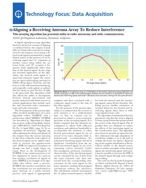
Technology Focus: Data AcquisitionA digital signal-processing algorithm has been devised as a means of aligning (as defined below) the outputs of mul-tiple receiving radio antennas in a large array for the purpose of receiving a de-sired weak signal transmitted by a single distant source in the presence of an in-terfering signal that (1) originates at another source lying within the an-tenna beam and (2) occupies a fre-quency band significantly wider than that of the desired signal. In the origi-nal intended application of the algo-rithm, the desired weak signal is a spacecraft telemetry signal, the anten-nas are spacecraft-tracking antennas in NASA’s Deep Space Network, and the source of the wide-band interfering sig-nal is typically a radio galaxy or a planet that lies along or near the line of sight to the spacecraft. The algorithm could also afford the ability to discriminate between desired narrow-band and nearby undesired wide-band sources in related applications that include satel-lite and terrestrial radio communica-tions and radio astronomy.The development of the present algo-rithm involved modification of a prior algorithm called “SUMPLE” and a predecessor called “SIMPLE.” SUMPLE was described in “Algorithm for Align-ing an Array of Receiving Radio Anten-nas” (NPO-40574), NASA Tech Briefs Vol. 30, No. 4 (April 2006), page 54. To re-capitulate: As used here, “aligning” sig-nifies adjusting the delays and phases of the outputs from the various antennas so that their relatively weak replicas of the desired signal can be added coher-ently to increase the signal-to-noise ratio (SNR) for improved reception, as though one had a single larger an-tenna. Prior to the development of SUMPLE, it was common practice to ef-fect alignment by means of a process that involves correlation of signals in pairs. SIMPLE is an example of an algo-rithm that effects such a process. SUMPLE also involves correlations, but the correlations are not performed in pairs. Instead, in a partly iterative process, each signal is appropriatelycomposite signal equal to the sum ofthe other signals.For the purpose of the present algo-rithm, it is assumed that the receiver ateach antenna is of a multi-channeltype, so that its outputs can beprocessed to obtain a cross-correlationspectrum of the incoming signals. It isfurther assumed that the channels areconfigured to afford both sufficientresolution and sufficient bandwidth toaccommodate the telemetry or otherdesired narrow-band signal by use ofseveral of its inner channels while si-multaneously accommodating thewide-band interfering signal, devoid ofsignificant contribution from the de-sired narrow-band signal, by use of itsremaining (outer) channels. Underthis assumption, pertinent correlationcharacteristics of the interfering signalcan be calculated by use of data fromthe outer channels only, then sub-tracted from the corresponding char-acteristics of the total signal in theinner channels, yielding desired-signalcorrelations without the interferer.The calculations include least-squaresfits of phase-versus-frequency modelsing signals, using all the channels. Thefitting process enables estimation ofresidual delays for the desired and in-terfering signals when there is suffi-cient signal-to-noise ratio.The algorithm as summarized thus farguarantees only that the array is alignedto form a pencil beam that points towardthe source of the desired signal. The al-gorithm does not eliminate or reducethe effects of the interfering signal onthe overall system noise. The algorithmdoes, however, provide an option for fur-ther refinement through adjustment ofcorrelation weights so as to tilt and/orreshape the beam (see figure). Depend-ing on the angular distribution of the in-terferer relative to the desired sourceand on relative strengths of the desiredsignal, the interfering signal, and noise,it may be possible to increase the SNR ofthe desired signal through such reshap-ing or tilting.This work was done by Andre P. Jongelingof Caltech and David H. Rogstad of SantaBarbara Applied Research for NASA’s JetPropulsion Laboratory. For more informa-tion, contact iaoffice@. NPO-45640Aligning a Receiving Antenna Array To Reduce InterferenceThis arraying algorithm has potential utility in radio astronomy and radio communication. NASA’s Jet Propulsion Laboratory, Pasadena, CaliforniaNASA Tech Briefs, August 20095。
A PROCESS AND DEVICE FOR CHANGING THE ACTUAL ROTAT

专利名称:A PROCESS AND DEVICE FOR CHANGING THE ACTUAL ROTATION SPEED OF AMULTI-PHASE NON-SYNCHRONOUSMOTOR AND A SUITABLE MOTOR SYSTEMFOR APPLYING THE PROCESS发明人:VOET, EDUARD, JOSEF申请号:EP89911758.4申请日:19891030公开号:EP0397818B1公开日:19930804专利内容由知识产权出版社提供摘要:the stator has a variable frequency changed according to a predetermined pattern. the rms value of the stator current, which is compared with the value of conduction.if it is higher, the frequency is kept constant.this corresponds to the set value of the speed of rotation, the process ends, otherwisethe frequency change is again as soon as the rms value is lower than the conduction.an alternative network is running, speed up or slow down the engine by means of a rectifier and an inverter.in the absence of the stator voltage is connected to a load resistor.the variation of the speed of rotation can be continuous or sinusoidal.the shape and dimensions of a sinusoidal component to give an indication of the torsional stiffness of the 'training'.from a set of a set of star triangle, we can extend the frequency range so as to maintain the torque is approximately constant.for the application of this process, we can implement a system of polyphase motors consists of asynchronous motors, and couple.provided with each other on the values of 2 and 3 as the ratio of characteristic values of the operating voltage andthe frequency of service.申请人:EUROPE PATENT LTD,EUROPE PATENT LTD地址:18, MERRION ROAD; DUBLIN 4,18, MERRION ROAD; DUBLIN 4代理机构:EGLI-EUROPEAN PATENT ATTORNEYS更多信息请下载全文后查看。
藻类水热反应与慢速热解
Thermochemical conversion of raw and defatted algal biomass via hydrothermal liquefaction and slow pyrolysisDerek R.Vardon a ,⇑,Brajendra K.Sharma b ,Grant V.Blazina a ,Kishore Rajagopalan b ,Timothy J.Strathmann aa Dept.of Civil and Environmental Engineering,University of Illinois at Urbana-Champaign,205N.Mathews Ave.,Urbana,IL 61801,United States bIllinois Sustainable Technology Center,University of Illinois at Urbana Champaign,1Hazelwood Dr.,Champaign,IL 61820,United Statesa r t i c l e i n f o Article history:Received 1November 2011Received in revised form 2January 2012Accepted 4January 2012Available online 10January 2012Keywords:AlgaeHydrothermal liquefaction Pyrolysis Scenedesmus Spirulinaa b s t r a c tThermochemical conversion is a promising route for recovering energy from algal biomass.Two thermo-chemical processes,hydrothermal liquefaction (HTL:300°C and 10–12MPa)and slow pyrolysis (heated to 450°C at a rate of 50°C/min),were used to produce bio-oils from Scenedesmus (raw and defatted)and Spirulina biomass that were compared against Illinois shale oil.Although both thermochemical conver-sion routes produced energy dense bio-oil (35–37MJ/kg)that approached shale oil (41MJ/kg),bio-oil yields (24–45%)and physico-chemical characteristics were highly influenced by conversion route and feedstock selection.Sharp differences were observed in the mean bio-oil molecular weight (pyrolysis 280–360Da;HTL 700–1330Da)and the percentage of low boiling compounds (bp <400°C)(pyrolysis 62–66%;HTL 45–54%).Analysis of the energy consumption ratio (ECR)also revealed that for wet algal biomass (80%moisture content),HTL is more favorable (ECR 0.44–0.63)than pyrolysis (ECR 0.92–1.24)due to required water volatilization in the latter technique.Ó2012Elsevier Ltd.All rights reserved.1.IntroductionAlgae are a diverse group of microorganisms that have garnered increased attention as a feedstock for renewable energy production and pollution remediation.Algae hold promise as a bioenergy feed-stock due to their prolific growth rate and lipid productivity,ability to grow in saline and degraded waterbodies,utilization of waste carbon dioxide,and production of fuel precursors and high-value biochemicals (Mata et al.,2009).Furthermore,integration of algal cultivation into wastewater treatment may be advantageous (Pitt-man et al.,2010)for nutrient capture to support algal growth and mitigate eutrophication in effluent-receiving water bodies.How-ever,despite these benefits,effective dewatering of harvested algal biomass for lipid extraction presents a current limitation to eco-nomical and sustainable biofuel production due to the high energy,operating,and capital costs (U.S.Department of Energy,2010).Many commercial efforts are underway to maximize economic return and improve energy balances in algal cultivation.Currently,much work is focused on extracting high value chemicals (e.g.,nutraceuticals)and energy-dense lipids (e.g.,for biodiesel)from al-gae,but this still leaves behind a large residual of ‘‘defatted’’bio-mass.Effective utilization of defatted algal biomass will be necessary to achieve favorable energy balances and productioncosts (Pan et al.,2010).Several downstream uses have been consid-ered for defatted algal biomass,including animal feed and fertil-izer,or as a feedstock for energy production through direct burning,ethanol fermentation,or anaerobic digestion (Mata et al.,2009).Here,we focus on examining the potential of different thermochemical conversion routes for recovering energy dense bio-oil products from raw and defatted algal biomass.Thermochemical conversion technologies are a promising op-tion for transforming diverse biomass feedstocks into energy dense,transportable liquid fuels that can combusted directly or upgraded into petroleum replacements (Bridgwater,2011;Duan and Savage,2011;Brown and Stevens,2011;Elliott,2007).Two thermochemical routes,hydrothermal liquefaction (HTL)and slow pyrolysis,were examined in this study to compare the chemical characteristics of bio-oils that can be produced from algal biomass,including defatted biomass.HTL is ideal for processing high-moisture (i.e.,wet)biomass since water is used as the reaction medium under high tempera-ture (250–350°C)and pressure (5–15MPa).These conditions pro-duce a highly reactive solvation environment and avoid an energetically costly phase change associated with biomass plex biomolecules decompose and reform into a variety of compounds that partition into a self-separating bio-oil phase when conditions return to ambient temperature and pressure.HTL has been tested with a wide range of biomass feedstocks including agricultural and forest residues (Minowa et al.,1998),manure,sewage sludge (Suzuki et al.,1988;Vardon et al.,2011),and several0960-8524/$-see front matter Ó2012Elsevier Ltd.All rights reserved.doi:10.1016/j.biortech.2012.01.008Corresponding author.Tel.:+12177663916.E-mail address:dvardon2@ (D.R.Vardon).algal species,including Spirulina(Jena et al.,2011;Vardon et al., 2011),Nannochloropsis(Biller and Ross,2011;Brown et al., 2010),and Chlorella(Biller and Ross,2011).Alternatively,pyrolysis technologies are best suited for the con-version of dry feedstocks(<5%moisture)since moisture must be removed before biomass is heated to high temperatures(400–600°C)under ambient pressure.The dried biomass is heated in the absence of oxygen to cleave and volatilize biomolecules,which re-condense into an aqueous and bio-oil phase;a carbon-rich solid phase,typically referred to as biochar,is also obtained.Pyrolysis technologies are often classified by their heating rate,with rates of0.1–1°C/s referred to as slow pyrolysis,10–200°C/s as fast pyro-lysis,and>1000°C/s asflash pyrolysis(Demirbas and Arin,2002). This study focused on slow pyrolysis due to its potential for pro-ducing more energy dense bio-oils that approach petroleum crude oils(Duman et al.,2010;Maggi and Delmon,1994).Pyrolysis has been studied extensively with lignocellulosic feedstocks and has been scaled to pilot and commercial production levels(Bridgwater, 2011;Brown and Stevens,2011).Non-traditional feedstocks have also been examined,such as hazelnut shells(Pütün et al.,1999), chicken litter,switch grass(Mullen et al.,2009),and cherry seed (Duman et al.,2010).Pyrolysis of several algal species have also been tested,including Chlorella(Demirbasß,2006;Miao et al., 2004;Peng et al.,2000;Grierson et al.,2009),heterotrophically en-hanced Chlorella(Miao and Wu,2004),Microcystis(Miao et al., 2004),salt-water Tetraselmis(Grierson et al.,2011,2009),and Nan-nochloropsis residue(Pan et al.,2010).Bio-oils produced from HTL and slow pyrolysis display diverse chemical properties that are heavily influenced by the source feed-stock composition.Algae of varying biochemical composition have been shown to produce bio-oils with distinct chemical characteris-tics(Grierson et al.,2009;Biller and Ross,2011;Jena et al.,2011), but to our knowledge no studies have examined how the chemistry of thermochemical bio-oils derived from defatted algal biomass compare to those produced from the parent algae(non-defatted) or other low-lipid algal species with composition similar to defatted algae biomass.This study examined thermochemical bio-oils pro-duced from raw and defatted Scenedesmus,a species with a range of lipid contents(10–55%)suitable for biodiesel production(Mata et al.,2009)and amenable for wastewater treatment(Pittman et al.,2010).These bio-oils were also compared with bio-oils pro-duced from thermochemical conversions of Spirulina,which has a nutritional profile similar to defatted algal biomass(i.e.,high pro-tein,low-lipid)that has been used as a feedstock in recent studies examining HTL(Biller and Ross,2011;Jena et al.,2011;Vardon et al.,2011).To our knowledge,this is thefirst study to examine ther-mochemical conversion of Scenedesmus biomass,in raw or defatted form,as well as thefirst study to directly compare the chemical properties of bio-oils produced from the different algal feedstocks via HTL and slow pyrolysis.The thermochemically-derived bio-oils were also compared with Illinois shale oil,a low-grade petroleum crude.Bio-oils and shale oil were analyzed for bulk properties (e.g.,elemental analysis and higher heating value)and physico-chemical characteristics(e.g.,molecular constituents,functional group allocation,proton speciation,molecular weight distribution, and boiling point distribution).Results were used to determine the influence of feedstock and thermochemical conversion method on bio-oil yield and chemistry and to evaluate the energy balances for algal biomass thermochemical conversions.2.Methods2.1.Algal feedstocks and shale oilScenedesmus biomass was provided by Stellarwind Bio Energy LLC(Indianapolis,IN)and Spirulina biomass was obtained from Cyanotech located in(Kailua-Kona,HI).Algal samples were used in dry powder form(moisture content<5%)and stored at5°C prior to processing.Scenedesmus biomass was defatted by using hexane in a Soxhlet extraction apparatus.Crude lipids were extracted until the recirculated solvent ran clear($24h).Illinois shale oil was ob-tained from the Illinois State Geological Survey(Champaign,IL).2.2.Thermochemical conversionAlgal biomass conversions with HTL and pyrolysis were con-ducted in triplicate batch reactions.Hydrothermal liquefaction was performed in a Parr4575500-ml reactor using approximately 250g of biomass slurry(80wt.%moisture).Conversion conditions were identical to those previously reported(Vardon et al.,2011), with30-min HTL reactions taking place at300°C,and pressure ranging from10to12MPa.Slow pyrolysis was conducted using a Thermolyne79400tube furnace.Approximately100g of dry bio-mass was loaded into the furnace chamber and heated to450°C at a rate of50°C/min,with a nitrogen sweep gasflow rate of $100ml/min and a reaction time of2h.Volatile products were condensed in an ice-chilled collection vessel while the remaining biomass solid(biochar)was collected and weighed separately.The liquid products obtained from HTL and slow pyrolysis con-tained a water-insoluble organic phase,suspended solids,and an aqueous phase with dissolved constituents.The combined liquid products were rinsed with dichloromethane(DCM)to separate the aqueous and DCM-soluble organics(Pütün et al.,1999;Peng et al.,2000;Grierson et al.,2011;Biller and Ross,2011;Brown et al.,2010;Duan and Savage,2011).A Teflon-coated stainless steel pressurizedfiltration assembly(Millipore)was then used to re-move suspended solids from the DCM and aqueous phases.Thefil-ter(Satorious0.45-l m cellulose membranes)and retained solids were recovered and dried to determine the mass of residual solids. Thefiltered DCM-soluble organics were then recovered using a separatory funnel and DCM was evaporated under reduced pres-sure to recover the bio-oil phase.For slow pyrolysis,the aqueous-phase included water-soluble constituents as well as water formed from biomass decomposition. For HTL,aqueous phase constituents consisted of total dissolved solids that were measured gravimetrically afterfiltration and evap-oration of the aqueous phase at65°C for$12h to remove water since it served as the reaction medium.The mass balance yields were calculated as the ratio of the cor-responding product phase to the initial dry feedstock mass,includ-ing ash.The bio-oil yield accounted for the mass of DCM-soluble organics recovered afterfiltration and DCM evaporation.For HTL, the aqueous phase yields accounted for the mass of dissolved aqueous constituents remaining after DCM extraction,filtration and water evaporation.For pyrolysis,the aqueous phase yields also accounted for re-condensed water evolved during the conversion process.The solid phase yields accounted for the mass of dried par-ticulates retained after DCM extraction andfiltration,plus the pyrolysis biochar residual remaining in the tube stly, the gas-phase yields were calculated based on the resulting mass difference.2.3.Feedstock and oil analysesForage analysis of the algal biomass was performed by Midwest Labs(Omaha,Nebraska)to determine crude protein,neutral deter-gentfiber(hemicellulose,cellulose,and lignin),acid detergentfiber (cellulose and lignin),lignin and ash content.Elemental analysis of the dried algal feedstocks,bio-oils,and shale oil was conducted by the University of Illinois Microanalysis Laboratory(Urbana,IL). Samples were processed for total carbon/hydrogen/nitrogen using an Exeter Analytical CE-440Elemental Analyzer.Sulfur wasD.R.Vardon et al./Bioresource Technology109(2012)178–187179measured by ICP-OES in axial mode(PerkinElmer Optima2000DV) after sample digestion(PerkinElmer Multiwave3000Digester).Bio-oils and shale oil were extensively characterized to obtain bulk and molecular characteristics using a variety of physico-chemical methods.Gas chromatography–mass spectroscopy(GC–MS)identified low-boiling point molecular constituents in the bio-oil and shale oil,attenuated total reflectance-Fourier Trans-form infrared(ATR-FTIR)and1H and13C nuclear magnetic reso-nance spectroscopy(NMR)provided information regarding ‘‘whole’’oil chemical functionality,size exclusion chromatography (SEC)evaluated the oil molecular weight distribution,and simu-lated distillation(Sim-Dist)determined the boiling point distribu-tion to provide insight into the composition of bio-oils in terms of equivalent petroleum products.These methods were described in detail previously(Vardon et al.,2011).Replicate bio-oils obtained from triplicate conversion reactions were analyzed separately by each method,with the exception of13C NMR analysis,which was only performed for a single replicate due to the high cost of analy-sis.Average values and standard deviations were reported.Since the focus of this study was on the influence of algal biomass com-position and conversion method on thermochemical bio-oil chem-istry,detailed analyses were not conducted on the aqueous,solid, or gas phase products.3.Results and discussion3.1.Feedstock compositionForage analysis revealed that crude protein was the predomi-nant fraction for all algal feedstocks(56–72%),with defatted Scene-desmus displaying the highest percentage(72%)(Table1).The high protein content is typical for many algal species investigated for biofuel production such as Nannochloropsis(52–57%)(Biller and Ross,2011;Brown et al.,2010)and Chlorella(51–55%)(Miao et al.,2004;Biller and Ross,2011;Peng et al.,2000).Total carbohy-drates ranged from20–25%,with raw and defatted Scenedesmus containing a significantly higher fraction of acid detergentfiber (ADF),comprised of cellulose and lignin.These recalcitrant fractions,particularly lignin,are less desirable components for thermochemical conversion.Their presence in biomass has been associated with lower HTL and pyrolysis bio-oil yields and bio-oil energetic contents compared to lipid,protein,and simple carbohy-drate components of biomass(Biller and Ross,2011;Minowa et al., 1998;Peng et al.,2000).Crude lipids were found to be a minor component of all three algal feedstocks,in decreasing order of raw Scenedesmus(13%),Spirulina(5%),and defatted Scenedesmus (<1%).While algal lipids are desirable for increasing thermochem-ical conversion bio-oil yields and energetic contents(Biller and Ross,2011;Miao and Wu,2004),greater economic return may be realized by extracting and processing lipids to obtain specialty biochemicals such as polyunsaturated fatty acids,carotenoids, and b-carotene(Mata et al.,2009).Due to the independent nature of forage assays,total carbohydrates,calculated by subtraction, were less than neutral detergentfiber(NDF)values for raw and defatted Scenedesmus biomass.Elemental analysis of the algal biomass revealed comparable car-bon(C),hydrogen(H),and nitrogen(N)values,with high N contents (8–10%)due to protein(Table1).The high N content greatly distin-guishes algal biomass from lignocellulosic feedstocks,which typi-cally contain<1%N(Mohan et al.,2006;Minowa et al.,1998). Interestingly,despite the significantly higher protein content of defatted Scenedesmus compared to raw Scenedesmus(72%and56% protein,respectively),the N content determined from elemental analysis was only$1%greater.Feedstock N is an important consid-eration because a significant portion can be carried over into the bio-oil products(Pan et al.,2010;Biller and Ross,2011;Brown et al., 2010;Jena et al.,2011;Miao et al.,2004),leading to problems with direct combustion(i.e.,NO x emissions)and creating additional tech-nical challenges when upgrading bio-oils.However,protein rich bio-mass may still be desirable because of the higher thermochemical bio-oil conversion efficiencies compared to those obtained with bio-mass that is richer in more recalcitrant carbohydrates and lignin. Furthermore,depending on its chemical form,N that partitions into the liquid or solid phase may also be useful as a fertilizer.Higher heating values(HHVs)of the dried algal feedstocks were calculated based on the elemental composition using Dulong’s for-mula and ranged from18to23MJ/kg.Raw Scenedesmus biomass had the highest energy content(23MJ/kg)due to its crude lipid content,with values similar to the moderate lipid species Chlorella (23–24MJ/kg)(Biller and Ross,2011;Demirbasß,2006).The HHV of defatted Scenedesmus biomass was lower as expected(21MJ/kg), and equivalent to past reports for defatted Nannochloropsis residue (Pan et al.,2010).Lastly,Spirulina biomass had the lowest HHV (18MJ/kg)due to high O content.3.2.Thermochemical conversion3.2.1.Mass balanceMass balances were highly dependent on the conversion process(i.e.,HTL or slow pyrolysis)and feedstock composition (Table2).HTL produced greater bio-oil yields for all feedstocks (7–14%higher than pyrolysis),calculated as a percentage of the dry biomass including ash,compared to slow pyrolysis under the conditions studied.Raw Scenedesmus resulted in the highest yield of HTL bio-oil(45%),followed by defatted Scenedesmus(36%),and Spirulina(31%).The range of HTL bio-oil yields was consistent with past reports for microalgae that vary based on nutritional profiles and conversion conditions(Brown et al.,2010;Biller and Ross, 2011;Jena et al.,2011;Vardon et al.,2011).The highest bio-oil conversion efficiency for raw Scenedesmus is likely due to the feed-stock’s high crude lipid and protein content,with previous studies identifying HTL conversion efficiencies in the order of lipid>pro-tein>carbohydrate(Biller and Ross,2011).Likewise,the greater bio-oil conversion efficiency of defatted Scenedesmus compared to Spirulina may be the result of higher crude protein of the former (Biller and Ross,2011);the high protein content of defatted Scene-desmus may offset the lower crude lipid content.Recalcitrant car-bohydrates and lignin can lead to reduced bio-oil yields(Minowa et al.,1998),possibly due to the condensation of phenolic com-pounds derived from lignin that result in the formation of residual solids(Toor et al.,2011).Table1Algal biomass nutritional profile,elemental analysis,and higher heating value(drybasis as wt.%).Feedstock Scenedesmus Defatted Scene.SpirulinaBiomass nutritional profileCrude Protein567264Crude Lipid13<15Total Carbohydrates252120Neutral Detergent Fiber32312Acid Detergent Fiber17161Lignin1113<1Organics949389Ash6711Biomass elemental analysis and HHVC52.149.945.2H7.47.1 6.4N8.89.99.8O*31.132.137.8S0.480.960.80HHV(MJ/kg)22.621.317.7*Oxygen content determined by difference for total mass.180 D.R.Vardon et al./Bioresource Technology109(2012)178–187Apart from the bio-oil fraction,the remaining feedstock was converted under HTL conditions into residual solid(6–11%),dis-solved aqueous constituents(17–23%),and gas phase products (30–41%).HTL solid yields were consistent with past reports for Spirulina(Jena et al.,2011);however,the dissolved aqueous con-stituents measured here were lower,which may be a byproduct of different approaches used to determine aqueous phase product yields.Aqueous phase organics can be derived from the decompo-sition of carbohydrates into polar,low molecular weight com-pounds such as formic,acetic,lactic,and acrylic acid(Biller and Ross,2011).The high volatility of these compounds may result in losses to the gas phase when measuring the yield of dissolved aqueous constituents by gravimetric analysis of total dissolved sol-ids remaining after water evaporation.Bio-oil yields obtained for slow pyrolysis were lower than for HTL,ranging from24%to31%,in the order of raw Scenedesmus> defatted Scenedesmus$Spirulina feedstocks.Similar to HTL,bio-oil conversion efficiencies were linked to feedstock composition. Previous pyrolysis studies with model biological compounds have shown that n-alkane liquid yields follow the order of lipids>pro-tein>cellulose>lignin(Evans and Felbeck,1983).Additionally, Miao and Wu(2004)demonstrated the beneficial effect of elevated lipid content for fast pyrolysis of microalgae,resulting in higher bio-oil yields and energetic contents.During pyrolysis,the remaining feedstock was converted into residual solid(30–33%),water and dissolved aqueous constituents (15–27%),and gas phase(12–21%),with the overall product distri-butions falling within the range of values previously reported for slow pyrolysis of microalgae(Grierson et al.,2009).The product phase distribution for slow pyrolysis of microalgae is influenced by the relative proportion of proteins,lipids,and carbohydrates (Grierson et al.,2009),which are known to decompose at lower temperatures compared to lignocellulose(Peng et al.,2000).The yield of dissolved aqueous constituents partially results from the degradation of cellulose and hemicellulose into water-soluble organics(Duman et al.,2010),while the gas phase yield has been shown to be highly dependent on process temperature due to sec-ondary cracking reactions(Peng et al.,2000).Lastly,the yield of so-lid biochar remaining after volatilization is of particular interest due to its soil amendment properties and carbon storage capacity (Grierson et al.,2011).3.2.2.Bulk propertiesElemental analysis of the bio-oils(Table3)demonstrated that HTL and slow pyrolysis produced bio-oils with a significantly high-er percentage of C(71–74%)and lower percentage of O(8–11%) compared to the initial feedstocks(45–52%C;31–38%O).How-ever,the nitrogen contents of the bio-oils(7–10%)remained nearly unchanged from the feedstocks(9–10%).The S content was minor for all bio-oils(0.4–1.4%),consistent with the low S content of the feedstocks(0.5–1.0%).In comparison,shale oil displayed a higher percentage of C(83%)and significantly lower percentages of O (6%)and N(0.7%)compared to the bio-oils.The total heteroatom content of the shale oil(8%N,O,and S)was less than half the val-ues measured for the bio-oils(17–20%N,O,and S).The large differ-ence in heteroatom contents represents a major distinction between bio-oils and petroleum crude oils,with the former requir-ing further processing for heteroatom reduction.The HHVs of the bio-oils(35–37MJ/kg)were significantly in-creased from the initial feedstocks(18–23MJ/kg),consistent with the large reductions in oxygen content.These values are slightly lower than the HHV estimated for the Illinois shale oil examined here(41MJ/kg)and petroleum crudes in general(41–48MJ/kg; (Speight,2001).HHVs of the HTL-derived bio-oils were consistent with previous reports for microalgae(33–40MJ/kg)(Biller and Ross,2011;Brown et al.,2010;Jena et al.,2011).For slow pyrolysis, the HHV of bio-oil produced from Spirulina(35MJ/kg)in this study was higher compared to past reports for bio-oil derived from the low-lipid microalgae Tetraselmis(28MJ/kg).Likewise,the bio-oil produced from defatted Scenedesmus(36MJ/kg)was greater than past reports for Nannochloropsis residue(24MJ/kg non-catalytic; 33MJ/kg catalytic)(Pan et al.,2010).Comparison of the HHV of pyrolysis bio-oils reported in different studies is complicated by differing conversion,recovery and aqueous phase separation meth-ods.For example,in this study DCM was used to recover the pyro-lysis bio-oil(Peng et al.,2000;Grierson et al.,2011;Pütün et al., 1999),resulting in negligible bio-oil moisture content.Residual water in the bio-oil can appear to increase the overall yield,but lower its HHV,as shown for wood-derived pyrolysis oils which typically range from15to25MJ/kg and contain15–30%water con-tent(Mohan et al.,2006).3.3.Bio-oil physico-chemical characterization3.3.1.Gas chromatography–mass spectroscopyAnalysis of low-boiling compounds(bp<350°C)in the bio-oil by GC–MS revealed distinct chemical class distributions for the major compounds comprising>1%of the total ion chromatogram (TIC)as shown in Table4(see Table S1in the Supplemental infor-mation for a full listing of major compounds).The bio-oils con-tained a much greater percentage of heteroatom compounds compared to Illinois shale oil,with the latter dominated by straight,branched,and cyclic hydrocarbons(56%).The remaining major compounds in Illinois shale oil were oxygenated,consistent with the oil’s5.9%O content and comparatively low N and S con-tents(<1%).In general,the major compounds in the HTL bio-oil identified by GC–MS consisted of cyclic nitrogenates(e.g.,pyrolle,indole,pyra-zine,and pyrimidine compounds),cyclic oxygenates(e.g.,phenols and phenol derivatives with aliphatic side-chains),and cyclic nitro-gen and oxygen compounds(e.g.,pyrrolidinedione,piperidinedi-one,and pyrrolizinedione compounds),similar with past reports of HTL bio-oils obtained from microalgae(Brown et al.,2010;Biller and Ross,2011;Jena et al.,2011).These compounds are likely de-rived from proteins,carbohydrates,and lignin in the feedstocks, which undergo a complex series of depolymerization,decomposi-tion,and reformation reactions,including Malliard reactions be-tween amino acids and sugars(Toor et al.,2011).As expected, HTL of defatted Scenedesmus produced bio-oil with the lowest frac-tion of hydrocarbons due to the negligible lipid content.The minor amount of fatty acids,esters,and hydrocarbons is likely due to the lower feedstock crude lipid content,since these compounds are known triglyceride decomposition products during thermochemi-cal conversion(Biller and Ross,2011;Miao and Wu,2004;Peterson et al.,2008).Triglycerides readily breakdown under HTL conditions to produce glycerol and fatty acids,the latter which can undergoTable2Mass balance of HTL and pyrolysis of algae(ash included)a.Feedstock Biocrude(%)Solids(%)Aqueous(%)Gaseous(%)bHydrothermal liquefactionScenedesmus45±47±217±230±3Defatted Scene.36±56±217±441±9Spirulina31±211±123±435±4Slow pyrolysisScenedesmus31±230±227±312±3Defatted Scene.24±333±121±221±2Spirulina24±130±215±315±3a Uncertainties represent standard deviations determined from triplicate ther-mochemical conversions.b Gaseous phase determined by difference for total recovery.D.R.Vardon et al./Bioresource Technology109(2012)178–187181decarboxylation and decarbonylation reactions to produce stable hydrocarbons(Peterson et al.,2008;Toor et al.,2011).Pyrolysis bio-oils displayed a significantly higher percentage of cyclic oxygenates(16–24%)compared to HTL bio-oils(8–12%),pri-marily in the form of phenolic compounds.Interestingly,pyrolysis bio-oil derived from Spirulina contained a higher percentage of straight-branched oxygenates compared to the Scenedesmus-de-rived bio-oils,which may be due to the larger percentage of simple carbohydrates in the feedstock.In contrast,lignin and cellulose have been shown to form primarily cyclic oxygenates that include phenolics,guaiacols,pyrogallols,and syringols,(Mohan et al., 2006;Demirbas and Arin,2002).Cyclic nitrogen compounds were also present in large amounts(9–13%),similar to past reports on pyrolysis bio-oils derived from Nannochloropsis residue(Pan et al.,2010),and consistent with contributions from protein com-ponents in the algal feedstocks.Pyrolysis of defatted Scenedesmus produced bio-oils with the lowest percentage of total hydrocarbons(straight,branched,and cyclic),similar to HTL-derived bio-oils;however,minor amounts of hydrocarbons were observed in both HTL and pyrolysis bio-oils, indicating that trace lipids remained in the feedstock or that pro-tein and carbohydrates were converted into hydrocarbons.As an example of the latter,during HTL small molecules produced from the decomposition,decarboxylation,and deamination of proteins may re-polymerize through Fischer–Tropsch-type reactions into hydrocarbons(Biller and Ross,2011;Peterson et al.,2008).Simi-larly,proteins have been shown to generate n-alkanes during pyro-lysis(Evans and Felbeck,1983).It should be emphasized that the GC–MS method was only able to characterize the low boiling frac-tion of the oils(bp<350°C)due to instrument temperature constraints.3.3.2.ATR-FTIR spectroscopyATR-FTIR spectroscopic analysis is consistent with the elevated heteroatom functionality of thermochemical bio-oils compared to Illinois shale oil(Fig.S1,Supplemental information).Significant peaks assigned to heteroatom-containing functional groups(Jena et al.,2011;Duan and Savage,2011;Pütün et al.,1999;Grierson et al.,2011)were observed in all bio-oil samples(1800–600cmÀ1)(Fig.S2,Supplemental information)despite prominent C A H stretch(3000–2840cmÀ1),CH2bending(1465cmÀ1),and CH3bending(1375cmÀ1)peaks.Strong absorbance between 1680–1600cmÀ1and1575–1525cmÀ1is observed for all bio-oils, possibly due to C@O stretching and N A H bending modes associ-ated with amide and amine compounds(Grierson et al.,2011). Nitrogenous functionality is consistent with compounds observed by GC–MS and similar peaks observed in slow pyrolysis bio-oil pro-duced from the microalgae Tetraselmis were attributed to protein-derived compounds(Grierson et al.,2011).The C@O stretching mode for carboxylic acids(1730–1700cmÀ1)was minor in all bio-oils,consistent with the relatively low crude lipid content of the feedstocks;however,no significant differences were observed between the bio-oils obtained from raw versus defatted feedstocks. In comparison,heteroatom peaks(1750–1500cmÀ1)were much smaller in spectra of Illinois shale oil,consistent with the lower heteroatom content and higher percentage of aliphatic compounds identified in shale oil.3.3.3.NMR spectroscopy1H NMR and13C NMR spectra provided further information regarding the proton and carbon speciation in bio-oils and Illinois shale oil(Figs.S3and S4,Supplemental information).The bio-oils displayed high aliphatic functionality(1H NMR0.5–1.5ppm;13C NMR0–55ppm),with>50%of the spectral area located in these re-gions(Fig.1and Fig.2).The high aliphatic functionality is consis-tent with the high bio-oil HHVs(Mullen et al.,2009)and the strong C A H peaks observed by FTIR.In comparison,spectra of low en-ergy–density bio-oils are reported to exhibit much less aliphatic functionality(Mullen et al.,2009).Previous work by Mullen et al. (2009)examined the aliphatic functionality of pyrolysis bio-oils derived from switch-grass(10%of1H NMR spectral area;21%of 13C NMR spectral area)and corn stover(11%of1H NMR spectral area;24%of13C NMR spectral area)(Mullen et al.,2009),which were significantly less compared to the algae-derived bio-oils examined in this study(50–55%of1H NMR spectral area;57–64%of13C NMR spectral area).13C NMR provided additional information by subdividing the aliphatic region into short aliphatics(0–28ppm;terminal methyl carbon,methylene carbon adjacent to terminus)and long/ branched aliphatics(28–55ppm;methylene carbon downstream from terminus,methylene carbon adjacent to branch points).HTL bio-oil derived from Scenedesmus(raw and defatted)displayed the highest fraction of long/branched aliphatic carbon in addition to the highest bio-oil M w(see below).This may be due to large oli-gomer compounds that contain a high fraction of methylene car-bon.Illinois shale oil also contained a high percentage of long/ branched aliphatic carbons,consistent with the high percentage of paraffin compounds identified by GC–MS.A significant fraction of the remaining spectral area for all bio-oils was assigned to aromatic and unsaturated functionality.13C NMR revealed that27–39%of the distributed carbon in the bio-oil was aromatic or unsaturated in nature.Similarly,34–43%of the dis-tributed protons detected by1H NMR were in the a-position to an unsaturated bond/heteroatom(1.5–3.0ppm)or contained in an aromatic/hetero-aromatic ring(6.0–8.5ppm).The observed func-tionality encompasses the wide range of alkene,heteroatom,aro-matic,and hetero-aromatic structures identified by GC–MS and peaks detected by ATR-FTIR.Likewise,Illinois shale oil displayedTable3Elemental analysis,higher heating value,and energy consumption ratio of thermochemical bio-oils and Illinois shale oil.aFeedstock C(%)H(%)N(%)O(%)S(%)HHV b(MJ/kg)ECRHydrothermal liquefaction bio-oilScenedesmus72.6±2.69.0±0.3 6.5±0.110.5±2.7 1.35±0.3135.50.44 Defatted Scene.72.2±0.68.9±0.17.8±0.310.5±0.50.90±0.4335.30.55 Spirulina72.2±2.39.1±0.38.1±0.29.2±2.8 1.41±0.5635.80.63Slow pyrolysis bio-oilScenedesmus73.9±2.39.3±0.27.9±0.38.1±2.60.84±0.1336.70.92 Defatted Scene.72.6±0.48.9±0.210.0±0.48.2±0.20.40±0.2835.7 1.22 Spirulina71.2±0.19.0±0.19.6±0.09.2±0.2 1.07±0.1335.2 1.24Shale oilIllinois shale oil82.89.90.7 5.90.7841.0-a Uncertainties represent standard deviations of bio-oils produced from independent thermochemical conversions conducted in triplicate.b HHVs obtained for moisture-free bio-oil following DCM extraction.182 D.R.Vardon et al./Bioresource Technology109(2012)178–187。
调整方法 英语作文

调整方法英语作文Title: Methods of Adjustment。
In our journey through life, we often encounter situations that require adjustment. Whether it's adaptingto a new environment, dealing with unexpected challenges,or simply striving for personal growth, the ability toadjust is crucial for success and well-being. In this essay, we will explore various methods of adjustment and their significance in navigating life's twists and turns.One of the fundamental methods of adjustment is maintaining a positive mindset. Optimism can be a powerful tool in facing adversity and overcoming obstacles. By focusing on the silver linings in difficult situations and believing in one's ability to overcome challenges, individuals can maintain resilience and keep moving forward. Cultivating gratitude and practicing mindfulness are effective ways to nurture a positive mindset, enabling individuals to find joy and fulfillment even in the face ofadversity.Another important method of adjustment is flexibility. Life is unpredictable, and rigid adherence to plans or expectations can lead to frustration and disappointment. By remaining flexible and open to change, individuals canadapt more easily to shifting circumstances and seize new opportunities that arise. This flexibility extends not only to external circumstances but also to internal beliefs and attitudes. Being willing to reevaluate one's perspectives and adjust them in light of new information or experiencesis essential for personal growth and development.Effective communication is also crucial for successful adjustment. Whether it's expressing needs and concerns, seeking support from others, or resolving conflicts, clear and open communication fosters understanding and cooperation. By effectively communicating their thoughtsand feelings, individuals can build stronger relationships and navigate social dynamics more effectively. Additionally, active listening is an important component of communication, allowing individuals to understand others' perspectives andcollaborate more effectively toward common goals.Furthermore, resilience is a key characteristic that facilitates adjustment in the face of adversity. Resilient individuals are able to bounce back from setbacks and setbacks, maintaining a sense of optimism and determination in the face of challenges. Building resilience involves developing coping strategies, cultivating social support networks, and learning from past experiences. By embracing resilience, individuals can navigate life's ups and downs with greater ease and confidence.Self-care is another vital aspect of adjustment. In order to thrive in the face of life's demands, individuals must prioritize their physical, emotional, and mental well-being. This may involve practicing healthy habits such as regular exercise, adequate sleep, and nutritious eating, as well as engaging in activities that bring joy and fulfillment. Taking time for self-reflection and introspection can also help individuals identify their needs and priorities, enabling them to make moreintentional choices and navigate life's challenges moreeffectively.Lastly, embracing a growth mindset can facilitate adjustment and personal development. A growth mindset is characterized by the belief that abilities and intelligence can be developed through effort and perseverance.Individuals with a growth mindset are more likely to view challenges as opportunities for learning and growth, rather than insurmountable obstacles. By embracing a growth mindset, individuals can cultivate resilience, adaptability, and a willingness to embrace change, ultimately leading to greater success and fulfillment in life.In conclusion, adjustment is an essential skill for navigating life's challenges and pursuing personal growth and fulfillment. By maintaining a positive mindset, remaining flexible, communicating effectively, building resilience, practicing self-care, and embracing a growth mindset, individuals can adapt more effectively to changing circumstances and thrive in the face of adversity. Through deliberate practice and reflection, we can cultivate these methods of adjustment and lead more fulfilling lives.。
鹅颈微调英语作文

The Art of Fine-tuning: A Metaphorical Journey Through the Goose NeckIn the vast expanse of life's complexities, the task of fine-tuning often presents itself as a delicate yet crucial endeavor. Similar to the intricate mechanism of a goose's neck, which enables it to gracefully navigate its surroundings, the art of fine-tuning requires a blend of precision, patience, and adaptability.The goose neck is a marvel of nature's engineering. Its flexibility allows the goose to effortlessly adjust its head and neck to reach for food, observe its surroundings, or communicate with other geese. This adaptability is a testament to the importance of being able to adjust and fine-tune oneself in response to changing circumstances.In the realm of personal development, fine-tuning often involves identifying areas for improvement and making subtle yet significant changes. It might be a matter of refining a skill, adjusting a habit, or cultivating a new mindset. Just as the goose neck adjusts to its environment, we must also learn to adapt and fine-tune ourselves to navigate the challenges and opportunities that life presents.The process of fine-tuning is not without its challenges. It requires a deep self-awareness and a willingness to embrace change. It might involve trial and error, and at times, we might feel as if we are making only incremental progress. However, it is this gradual and steady refinement that ultimately leads to significant transformations.Moreover, fine-tuning is not just about making changes within oneself. It also involves adjusting one's interactions with others and the environment. Just as the goose neck enables the goose to communicate and cooperate with others, we must also learn to fine-tune our relationships and our approach to the world.In conclusion, the metaphor of the goose neck serves as a powerful reminder of the importance of fine-tuning in life. Whether it is in personal development, relationships, or career aspirations, the ability to identify areas for improvement and make subtle yet significant changes is crucial. By embracing the art of fine-tuning, we can navigate the complexities of life with greater ease and grace.。
LMF Series 550 in
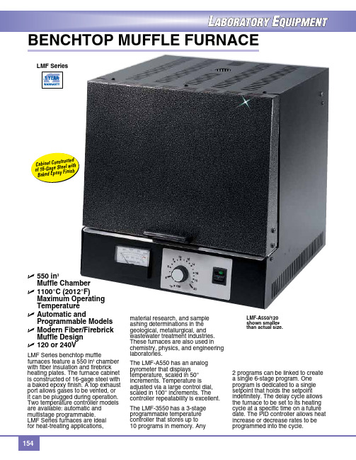
U 550 in3Muffle ChamberU 1100°C (2012°F)Maximum OperatingTemperatureU Automatic andProgrammable ModelsU Modern Fiber/Firebrick Muffle DesignU 120 or 240VLMF Series benchtop muffle furnaces feature a 550 in3 chamber with fiber insulation and firebrick heating plates. The furnace cabinet is constructed of 16‑gage steel with a baked epoxy finish. A top exhaust port allows gases to be vented, or it can be plugged during operation. Two temperature controller models are available: automatic and multistage programmable.LMF Series furnaces are idealfor heat‑treating applications, material research, and sampleashing determinations in thegeological, metallurgical, andwastewater treatment industries.These furnaces are also used inchemistry, physics, and engineeringlaboratories.The LMF‑A550 has an analogpyrometer that displaystemperature, scaled in 50°increments. Temperature isadjusted via a large control dial,scaled in 100° increments. Thecontroller repeatability is excellent.The LMF‑3550 has a 3‑stageprogrammable temperaturecontroller that stores up to10 programs in memory. Any2 programs can be linked to createa single 6‑stage program. Oneprogram is dedicated to a singlesetpoint that holds the setpointindefinitely. The delay cycle allowsthe furnace to be set to its heatingcycle at a specific time on a futuredate. The PID controller allows heatincrease or decrease rates to beprogrammed into the cycle.LMF‑A550/120shown smallerthan actual size.benChTOP MuFFLe FurnACeSpecificationsCabinet Dimensions:41 H x 40 W x 39 cm D(16.0 x 15.7 x 15.3")Cabinet Construction: 16‑gage steel with baked epoxy finishChamber Size: 9.13 L (550 in3) Chamber Dimensions:18 H x 23 W x 23 cm D (7 x 9 x 9") electrical requirements:15 A @ 120V, 50/60 Hz;7.5 A @ 240V, 50/60 HzPower Consumption: 1800 W Watts to Maintain 1000°C: 1025 W Operating Temp range:LMF‑A550: 200 to 1100°C (392 to 2012°F)LMF‑3550: 50 to 1100°C(122 to 2012°F)Air Circulation: Top exhaust port Muffle: Fiber insulation with firebrick heating plates1000 1832 50 200 392 180 LMF-TRAY, spare ceramic floor tray.** Time to cool down from 1100°C (2012°F) to indicated temperature with no load.Analog prometer displays temperatures onLMF‑A550 models.LMF‑3550/120 shown smaller than actual size.LMF‑3550 models feature digital display with 3‑stage programmable temperature controller.。
Furnace

Furnace Reference Manual Tempress Systems Inc.Furnace manualM320_01 January 2004This page in tention ally left blankTable of contents1. Introduction..........................................................1-11.1Scope of the manual.................................................................1-11.2Furnace models........................................................................1-12. Description...........................................................2-12.1Diffusion system........................................................................2-12.2Components of the furnace.......................................................2-32.3Furnace cabinet........................................................................2-42.4Scavenger.................................................................................2-42.4.1Available models........................................................2-42.4.2Description of the Scavenger.....................................2-42.5Cooling unit...............................................................................2-52.6Fast Cooldown..........................................................................2-62.7Heating elements (disposacore)...............................................2-72.7.1Tube heating module.................................................2-72.7.2Heating elements, tube adapters, isolation collars....2-82.8Support and sealing................................................................2-102.9Furnace temperature control...................................................2-113. Installation............................................................3-13.1Introduction...............................................................................3-13.2Unpacking.................................................................................3-13.3Installation.................................................................................3-23.4The furnace...............................................................................3-23.5The scavenger..........................................................................3-33.6Inspection.................................................................................3-34. Start-up.................................................................4-14.1Introduction...............................................................................4-14.2Start-up.....................................................................................4-14.3Fast Cooldown..........................................................................4-34.4Burn-in and Oxidation of an Heating element...........................4-34.5Installation of the Quartz Tube..................................................4-54.6Test and Calibration Procedure................................................4-64.7Pre-Cleaning of the Process Tube............................................4-64.8Automatic profiling procedure...................................................4-84.8.1Automatic profiling procedure....................................4-84.8.1.1Introduction to profiling................................4-84.8.1.2Profiling recipe setup...................................4-94.8.2automatic profiling preparation................................4-114.8.3Paddle TC installation..............................................4-114.8.3.1Profile recipe selection..............................4-124.8.4Automatic profiling RUN..........................................4-124.8.5Summary automatic profiling...................................4-135. Maintenance.........................................................5-15.1Introduction...............................................................................5-15.2Heating Element Coil................................................................5-15.3Heating elements......................................................................5-35.4The SCR-Module......................................................................5-35.5Heat Exchanger........................................................................5-45.6Tube change.............................................................................5-55.7Tube change diffusion system tubes.........................................5-55.8Tube change LPCVD and vacuum system tubes.....................5-65.9Preventive Maintenance...........................................................5-76. Calibration/Adjustments.....................................6-17. Trouble Shooting.................................................7-1LIST OF FIGURESList of figuresFigure 2-1 Outline drawing of a Furnace System, model TS6804..........2-2 Figure 2-2 Round scavenger box layout (Diffusion)...............................2-5 Figure 2-3 Cooling unit...........................................................................2-5 Figure 2-4 Fast Cooldown principle........................................................2-6 Figure 2-5 Heating element for diffusion furnaces..................................2-8 Figure 2-6 Tube adaptors, support and radiation heat shield...............2-10 Figure 2-7 Zone paddle profiling thermocouple....................................2-11 Figure 2-8 Double spike thermocouple.................................................2-11 Figure 4-1: Spike thermocouple..............................................................4-2 Figure 4-2: Tube adapter.........................................................................4-2 Figure 4-3: P osition of the thermocouple.................................................4-5 Figure 5-1 The heating element adjustment............................................5-21.Introduction1.1 Scope of the manualThe contents of this manual and drawings are to provide the necessary instructions and information for installing, adjustment, operating, maintenance and understanding of the Amtech/Tempress Systems Furnace. Before starting up, installing, operating and/or maintaining the system, read this manual first.1.2 Furnace modelsThis manual is meant for the following Tempress Diffusion models:Model number WafersizeCapabilityNr of tubes Flat-zone lengthTS-6300 seriesTS-6303TS-6304 150 mm 3425-30 cm(12 inch)TS-6600 seriesTS-6603TS-6604 150 mm 3455-60 cm(24 inch)TS-6800 seriesTS-6803TS-6804150 mm 3475-80 cm(32 inch)TS-61000 seriesTS-61003TS-61004 150 mm 3495-100 cm(40 inch)TS-8600 seriesTS-8603TS-8604200 mm 3455-60 cm(24 inch)TS-81000 seriesTS-81003TS-81004 200 mm 3495-100 cm(40 inch)TS-12800 seriesTS-12803 TS-12804 300 mm 2375-80(32 inch)Table 1 Different types of furnace modelsThe TS-6000 seriesThe TS-6000 series is a line of horizontal furnaces for up to 150 mm. (6 inch) wafers. This system is standard equipped with an accurate 3 zone digital controller for optimum temperature control.In this line the following models are available:•TS-6300 series:Designed for 150 mm R&D institutes. With its flatzone of 30 cm,loads of 25 to 50 wafers can be processed.•TS-6600 series:Designed for small batch or pilot production, 150 mm facilities.With its flatzone of 60 cm, loads of 50 to 100 wafers can beprocessed.• TS-6800 series:Designed for 150 mm production facilities. With its flatzone of 80cm, loads of 100 to 200 wafers can be processed.•TS-61000 series:Designed for high volume, 150 mm production facilities. With itsflatzone of 100 cm, loads of 150 to 300 wafers can be processed.The TS-8000 seriesThe TS-8000 series is a line of horizontal furnaces for up to 200 mm. (8 inch) wafers. These systems are equipped with an accurate 5 zone digital controller for optimum temperature control.In this line the following models are available:•TS-8600 series:Designed for small batch or pilot production, 200 mm facilities.With its flatzone of 60 cm, loads of 50 to 100 wafers can beprocessed•TS-81000 series:Designed for high volume production, 200 mm facilities. With itsflatzone of 100 cm, loads of 100 to 200 wafers can be processed.The TS-12800 seriesThe TS-12800 series is a line of horizontal furnaces for up to 300 mm. (12 inch) wafers. These systems are equipped with an accurate 5 zone digital controller for optimum temperature control.In this line the following models is available:•TS-12800 series: Designed for high volume production, 300 mm facilities. With itsflatzone of 80 cm, loads of 100 to 150 wafers can be processed.2.Description2.1 Diffusion systemThe Furnace is designed to perform Diffusion/Atmospheric and Low Pressure Chemical Vapor Deposition (LPCVD) processing on wafers from 75 mm up to 300 mm, and may be installed in a cleanroom environment.The furnace is housed in a utilized cabinet of heavy gauge metal construction with a Clean Room Compatible Polyurethane finish. It contains max. 4 heating elements. Within the furnace the heating elements are numbered from 1 to 4, starting with tube number 1 at the top. The heat exchanger on the top of the furnace cools the exhausted air (a water-cooled mantle for each tube is available as an option). Three phase power transformers are used to maintain a constant temperature with a minimum of disturbance on the mainpower distribution system.The integrated modular construction provides discrete compartments for control equipment. All electrical wiring, including the basic units of the temperature controller and electrical components are housed in the base of the furnace.The diffusion system may have a right or left handed orientation to suit the customers needs (furnace on the right when standing in front of the loadstation means a right-handed system). Major components of the diffusion system are:Station• Load•Furnace System•Cross flow box (Horizontal or Vertical Flow Loadstation)Cabinet• Gas• ControlsystemOn the next page an outline drawing of a Furnace System, model TS6804 is shown:Figure 2-1 Outline drawing of a Furnace System, model TS6804A: top view of the furnace with scavenger1: Water outlet Bulkhead Swagelok (furnace cooling)2: Water inlet Bulkhead Swagelok (furnace cooling)3: Exhaust Furnace4: Water outlet Bulkhead Swagelok (cooling vacuum-flanges) 5: Water inlet Bulkhead Swagelok (cooling vacuum-flanges) 6: Exhaust scavenger-box7: Exhaust scavenger-housingB: sideview of the furnaceC: frontview of the furnace8: Scavenger box exhaust.9: Tube switch10: Key switch control power on-off11: Mainswitch (lockable in off-position)12: Mainpowerconnection13: Excess Temperature ControllerD: view of the loadside of the furnace8: Scavenger-box exhaustE: rearside of the furnace8: Scavenger-box exhaust2.2 Components of the furnace• Furnace cabinet• Scavenger• Cooling unit• Fast Cool down• Heating elements• Tube (support and sealing)• Flange• Furnace Temperature Control• Power supply• Main switch assembly2.3 Furnace cabinetThe furnace is housed in a utilized cabinet of heavy gauge metal construction with a Clean Room Compatible Polyurethane finish. (See Figure 2-1).•Optional: Cabinet over-temperature protection sensor on top of the cabinet.2.4 ScavengerAll 3-stack and 4-stack furnaces are provided with a toxic gas scavenger. Depending on the application, with or without a front door.2.4.1 Available modelsA) Stainless steel round box with adjustable outlet in the box and one exhaust pipe withoutlet on the top of the furnace on which all boxes are connected. Normally used for OMEGA-Juniors and all one-stack furnaces.B) Same as A, however with the provision that service now can be done from themaintenance room. Each box provided with a separate outlet to the top of the furnace with adjustable valve. All outlets on the top connected to a manifold. Used for furnaces with automatically boatloading, cantilever systems etc.2.4.2 Description of the Scavenger•Sealing between clean room and service room.•One exhaust connection on top, there is however also an exhaust connection possible on the bottom (optional).•Door for maintenance on the service side.•Stainless steel round scavengers.•Each compartment is exhausted and adjustable independently.•Each compartment has an individual monitor for the scavenger pressure (optional).Figure 2-2 Round scavenger box layout (Diffusion)2.5 Cooling unitThe cooling module is mounted on the top of the furnace. It is a water/air heat exchanger, with high-efficiency aluminium fins, for optimised surface area. The water quantity (preferably soft water) is 3-7 l/min, depending on the inlet water temperature. (see Figure 2-1 and Figure 2-3) The electrical fans on top of the module extract the hot air through the radiator fins and cooled air is blown-out in the room again. The fans start running, as soon as the main switch of the furnace is switched on.Figure 2-3 Cooling unit2.6 Fast CooldownAir is forced by a blower to travel between the heating element mantle and the outside of the process tube. The direction of airflow is alternated to achieve balanced cooling faster than the conventional furnace.The air used for cooling is re-circulated. It is cooled by a water-cooled heat exchanger built in, in the furnace cabinet.The blower is a centrifugal type. The speed is controlled by the DTC and is varied according to requirements. The blower is connected to the heat exchanger and heating element via tubing. The Cool down modules (blower and heat exchanger) are both situated behind the heating elements.Cooling ProcessCool down is assisted by conditioned air that is forced to flow between the heating element and the process tube (Figure 2-4). The flow of air is periodically reversed left-to-right; right-to-left to equalize out the cooling effect over the whole wafer load. During cool-down, only paddle thermocouples are used for temperature measurement. The flowing past the spike thermocouples makes their use inaccurate.Figure 2-4 Fast Cooldown principleControl of the valves and blower during cool-down is done by the DTC which has dedicated software for the purpose. The cool rate in the temperature table determines the cool down time and the DTC attempts to maintain this rate over all zones.At the start of the cool-down step, the DTC checks the current temperature setpoint, the paddle setpoint (target temperature) and the ramp (slope) to see if forced cooling is necessary. If it is, the DTC calculates a profile (temperature over time) required to reach the target setpoint, and sets the blower speed to an appropriate value (determined by an algorithm). While cooling is in progress, the DTC applies power to the element end zone to maintain an even cooling “ramp” and to maintain a flat zone.When the system reaches the paddle setpoint, the blower is ramped down and turned off. At this point the DTC switches automatically back to cascade control.2.7 Heating elements (disposacore)•The furnace contains 3 or 5 zone heating elements of the standard Tempress Systems specification and are used for optimum temperature characteristics.•The furnace can contain any of the following heating elements: a multipurpose Kanthal A-1 coil, a high temp APM coil, an ultra high temp Kanthal Superthal® coil, Low temp white John, MRL heating elements or light Gauge for high/low temperature applications. Insulation made from high purity, high density, vacuum molded alumina silica fiber(optional light Gauge). It depends on the process temperature, which kind of element is used. Custom desired other elements can be implemented on request.•Over temperature protection is provided by an Excess Temperature Controller, connected to separate Thermocouples. See section Error! Reference source not found.•Each heating element has its own transformer with isolated coils powering individual control zones via high-efficiency zero-crossover fired Silicon Control Rectifier (SCR) power control modules.•One tube switch per heating element, to shut off one tube only.•Tube sizes depending on customer demand.•The combination of the special coil-design, insulation, stainless steel shell and the DTC guarantees:• better uniformity• long lifetime• energy saving• no element sagging2.7.1 Tube heating moduleThis module, most of the times multi-zone, consists of a Fibrothal® heating element with embedded Kanthal alloys and a stainless steel mantle. This module is meant for diffusion furnaces. See Figure 2-5.The advantages of this construction are:• High temperature equability• Exact temperature profile• High operating capacityCONNECTOR FOR POWERSTAINLESS STEEL MANTLELife-time and maximum temperatureThe typical lifetime of a heating element is 5-15 years but is highly dependent on many factors. Strong temperature fluctuation and high temperature may reduce the actual lifetime.Note: Keep in maximum recommended temperature, overshoot will highly increasethe ageing of the heating element. 2.7.2Heating elements, tube adapters, isolation collarsKanthal heating elements are isolated with ceramic fiber material. If the material is disturbed, fibrous dust may be generated. This dust may be carcinogenic.DANGERIf the temperature exceeds 900°C, silcogene chemicals such as Kristobalite may be formed. Use appropriate safety measures. See Material Safety Data Sheet.General Precautions•Read the Material Safety Data Sheet and follow the advice and procedures they contain.• Wear protective clothing and equipment appropriate for the hazard, this include overall, hat, dust mask (with a particulate air filter cartridge to DIN 3181 P3),goggles and gloves.• Reduce underfoot debris, keep the work area clean.• Use a vacuum cleaner with a HEPA filter.• Work in a controlled and careful manner to avoid dust generation and dispersionHandling• Never saw, cut or sand silicate fiber material.• Double-bag, seal and label heating elements for transport.• Treat heating elements and silicate fiber as chemical waste.Chemical propertiesThe ceramic fiber modules contain a high chemical resistance except liquid acids, phosphoric acids and strong bases. Moistening with water or oil doesn’t influence the properties of ceramic fiber itself. After drying respectively evaporation, the thermal and physical properties will be set to their normal conditions.Be careful with the material in combination with heating elements, because of possible corrosionSafety prescriptionsHealth Inhalation can cause health injuries. Avoid contact with skin oreyes.First aid In case of contacting with skin or eyes: don’t rub, but flushimmediately with ample water.Protection measures air-exhaust, Dust-mask P2, Goggle and Working clothes with longsleevesLabor hygiene wash unprotected skin surfaces thoroughly with water.Gather working clothes separate.2.8 Support and sealing•Tubes may be supported by tube supports and centered by tube adapters. The use of tube supports for high temperature elements is not recommended.•Radiation heat shield (1 per tube), made of Moldatherm® insulation plate and covered with an aluminium or stainless steel cover.• Tight sealing between tube and scavenger (optional).Figure 2-6 Tube adaptors, support and radiation heat shield2.9 Furnace temperature control•The Digital Temperature Controller provides master/slave or independent zone control. It features proportional, integral and derivative (PID) temperature control functions.•Digital Temperature Controller, with 3 to 5 zone spike (optional) and paddle control per tube. Ramping, limit alarms, TC break and power failure alarms and 4 temperature recipes.•Thermal flatzone is depending on the type of furnace.•Double spike thermocouples, one for temperature control and one for the Excess Temperature protection.•Tripple thermocouples, two are for the spike control (in case of failure of one) and the third one is for the Excess Temperature protection.•Optional other control system, see separate manuals.•Thermocouple connections on source or load side of the furnace, for Paddle controlFigure 2-7 Zone paddle profiling thermocoupleFigure 2-8 Double spike thermocouple3.Installation3.1 IntroductionIn this chapter contains a detailed description about the unpacking, installation and inspection procedures. When the furnace is moved in transit and during final placement at the customer's facility, care should be exercised at all times.CAUTIONTransport of the system should be in an upright position at all times.3.2 Unpacking•Before the furnace is unpacked, a visual inspection of packing materials should be made. If there is evidence of damage during transport, the carrier should be contacted so that an inspector can be present to verify any damage before the furnace is unpacked.• If there is any visible damage, notify Amtech/Tempress Systems verbally and in writing. This must be done within 24 hours, after arrival of the shipment.• available to move/carry the furnace in its right place.CAUTIONThe furnace is packed in 2 layers of plastic. The first layer must be removed outside the clean room. The second layer must be removed in the clean room.Unpacking: •Check off all boxes against the packing list. • Unpack the boxes one by one.• Check the contents of the boxes against the collo contents list • If any damage is visible, then....CAUTIONDo not dispose any of the packing materials or boxes.• Release and remove equipment wrappings.CAUTIONLift or pull the wrappings away from all stainless steelsurfaces. Do not drag packing materials across theequipment surfaces as this may cause damage.•Depending what type of packing material is being used; a final de-dusting must be done before it is put into position. The system has been pre-cleaned before leaving our factory.3.3 InstallationCAUTIONDuring movement, the furnace assembly is slightlyunstable and should be considered top heavy.3.4 The furnaceCAUTIONItems, described in this paragraph, are the customer'sresponsibility.•Check the bottom side of the furnace for levelers and sagged wires.•To prevent moving of the furnace during perpendicular lift up, use wooden packing block.•Locate the furnace in its final position.CAUTIONThe tines of the forklift should extend under completewidth of the furnace when moving.•Place a spirit-level on top of the furnace. The furnace can then be leveled, by adjusting the adjustable feet on the bottom of the furnace.•Locate the loadstation and the gascabinet in their position.•Level and align the loadstation and the gascabinet with respect to the furnace. •Install all facilities as indicated on the outline drawing and verify that they comply with the labeling.INSTALLATIONCAUTIONDo not turn on any of the services which areconnected. This may only be done in the presence of aqualified engineer from Amtech/Tempress Systems,unless prior permission gained fromAmtech/Tempress systems, in writing.•Final alignment and facility functionality will be checked by the Amtech/Tempress Systems-engineer.•The Amtech/Tempress Systems engineer will do purging of all toxic gas lines.3.5 The scavenger• Scavengerexhaust(standard) duct has a 108 mm O.D. outlet (check for the right O.D. the outline drawing). Therefore, install the stainless steel exhaust lines to the exhaust system. They must meet the state and local regulations for treatment and exhausting of the toxic, corrosive and pyrophoric gasses.•The exhaust rate should be around 100 l/min. (per tube level).3.6 Inspection•Check for any parts that may have loosened or become free during transit (especially the electrical connections and power leads), and check all components for damage. •Check if the tube switches on the furnace are "OFF".•Check for the correct voltage, on main power connection/label, attached close to the main power terminals.•Check if the cabling is correctly connected.DANGER OF LIFEHigh voltage may cause serious injury or may be fatal. It isessential that all safety guidelines will be followed whenworking with high voltage equipment.4.Start-up4.1 IntroductionAfter the furnace is installed and leveled correctly, the start-up may begin.Definition of Chapter Contents:• Pre-operation checks. •Burn in elements.• Tube installation. • As this is a general start-up procedure for diffusion furnaces, some items are optional. These items are also marked as optional in the following sections.NOTE: the start-up of the system is the AMTECH/tempress -field-serviceengineersresponsibility.In case of emergency or system failure, press the EMO-button for a complete system power down. These red EMO buttons are placed on the upper front of the Remotes Control Console or loadstation and on the back of the furnace (Optional).4.2 Start-upMaterials requirement: • Quartz wool.• Digital Voltmeter (= D.V.M.). •Accurate room temperature meter, 1 Decimal Point (=1 D.P.).• Propan-2-ol (I.P.A.) •Clean room gloves.• Clean wipes. •Clamp type Ampere meter 0-200 Amperes minimum range.Actual Start-up: • Place and connect TC's. Note that red is negative . Each ceramic housing for thethermocouple has two pairs of Thermocouples within it. The wires for each thermocouple are twisted together. •Adjust the Thermocouples so that they are just visible (only 2 mm) from inside the heating element.•For element oxidation, the outer ends of the heating element have to be closed by using heat resistant insulating material, such as quartz wool (to be provided by the customer).Figure 4-1: Spike thermocouple Figure 4-2: Tube adapter•Place the tube adapters on a level surface, with the large end down and pack with quartz wool. Ensure it will not fall from the tube adapters when they are moved and no foreign material has been incorporated in the quartz wool.CAUTIONTube adapters are used to prevent air movement between theheating element and the process tube. Air movement may begenerated by differential pressures between the cleanroom and thearea outside the cleanroom. Temperature may be substantiallyaffected by any airflow past the thermocouple junctions.•Place the tube adapters in the front and in the rear of the heating elements. •Check if the electrical connections on the heating element are tight. Due to the high currents in these cables, any loose connections may damage the control circuitry and the element.•Check if the cabling is properly connected and check for the correct voltage. •Check if the terminal strip connections are tightened.•Check if the water supply and the scavenger exhaust are- connected according to the outline drawing.•Check if all system power switches on the furnace are switched off.•If present, check if the EMO-switches operate correctly.•Turn on the ‘House Power Supply' to the furnace and check if the Phase voltages are correct at the main power input connections.•If present, turn on the main power switch.。
HELLA Gutmann SEG系列头灯调整设备说明书

Headlight adjustment devices that can do it all•Analogue and digital headlight setting with the lighting and diagnostic know-how of HELLA and Hella Gutmann•Digital adjustment device with integrated vehicle database and headlight-specific algorithms•Hybrid visor for correct alignment in every situationIhringen, 8. November 2021. Modern vehicle headlights score points with their large headlight range, light waves similar to daylight, and optimum illumination with minimal glaring for other road users. Added to this is the growing comfort provided by advanced high-beam assistant systems. But with the diversity of lighting systems, the challenge of correct headlight settings is growing. Hella Gutmann's SEG series headlight adjustment devices provide reliable and user-friendly solutions for the individual needs of a workshop.Already the analog SEG IV SE has a lot to offer. The robust device with large rubberized wheels and a heavy base made of polymer concrete accommodates highly accurate optics and enables the evaluation of all standard light distributions of modern headlight systems on a wide variety of brands. Practice-oriented functionalities and easy handling ensure the quality of the settings. A standard hybrid visor, consisting of a powerful line laser and an analog sighting device on an extra-long column, predestines the analog SEG IV SE for universal use on different vehicle classes. Even the exterior marking points of particularly wide vehicles, such as motor homes and large commercial vehicles, can be easily targeted via the wide laser beam angle of 120°. Regardless of the surrounding brightness and the condition of the battery, the device can also be precisely aligned to the vehicle by means of an analog sighting device.The state-of-the-art SEG V digital headlight alignment unit is also aligned orthogonally to the vehicle via a standard-feature hybrid visor. In addition, the camera-based SEG V offers an integrated vehicle database, automatic compensation of ground unevenness and inclination, and the option of documenting the measurement results. The user-friendly device can be used on a wide range of vehicle classes, headlighttypes and light sources, including laser headlights. It has all the functions that are standard in this device category and, in addition, a special Hella Gutmann feature: the database integrated in the SEG V with vehicle- and headlight-specific algorithms and target data forms the basis for reliable selection, calibration and basic setting of high-beam assistants.After selecting the vehicle and the headlight type, the SEG V automatically detects deviations from target data using the stored algorithms and guides the user through the adjustment process until the correct result is achieved. For this purpose, the images from the high-resolution CMOS camera are evaluated by the device in real time and displayed on the touchscreen with auxiliary or tolerance lines and correction instructions. Each headlight setting can be documented with exact values and images via ASA network connection to the workshop management system or via export via USB or WLAN interface.Thanks to an electronic position sensor in the unit, ground unevenness of up to 2% in the x and y axes is automatically compensated. In addition, there is the option of manual presetting, which can also be used to compensate for different inclinations of the unit and the vehicle footprint. All functions of the digital headlight leveller can be selected via the 8.4" touchscreen. The operator always has the choice of switching between automatic and manual mode in the measuring menu. The latter makes it easier to check and adjust weak light distributions, for example with fog lights or older headlight types.The SEG IV as well as the SEG V can optionally be operated even more efficiently on a leveling rail system with matching wheels. Another option for meeting the german requirements for the headlight levelling within a directive-compliant headlamp stabling area for HU is Hella Gutmann's leveling plate system, which is also optional.Note: You can also find this text and related images in our press database at:/de/hella-gutmann/presse/ or https:///hella-com/en/Press-7633.htmlHella Gutmann Solutions GmbH, Ihringen: The company with around 500 employees and headquarters in Ihringen/Breisach, Germany, is part of the Hella Gutmann Group, a company of HELLA GmbH & Co. KGaA. The product portfolio focuses on professional equipment for automotive workshops, car dealerships and aautomotive testing agencies. Core products are data, software, devices and tools for diagnostics, exhaust emission tests, headlight adjustment, system checks and the associated measuring technology. Some 45,000 automotive companies in 24 countries utilise the tools and professional expertise of Hella Gutmann Solutions on a daily basis. They benefit from high level German quality standards and customer-oriented services such as our Technical Help Line, technical training, technical data and support with sales and marketing.Get more information from:Hella Gutmann Solutions GmbH HELLA GmbH & Co. KGaAUschi Winkler Dr Markus RichterPress Company spokespersonAm Krebsbach 2 Rixbecker Strasse 7579241 Ihringen, Germany 59552 Lippstadt, GermanyTel.: +49 (0)8033 3023 290 Tel: +49 (0)2941 38-7545Mobile: +49 (0)171 837 9251 Fax: +49 (0)2941 38-477545************************************************ 。
- 1、下载文档前请自行甄别文档内容的完整性,平台不提供额外的编辑、内容补充、找答案等附加服务。
- 2、"仅部分预览"的文档,不可在线预览部分如存在完整性等问题,可反馈申请退款(可完整预览的文档不适用该条件!)。
- 3、如文档侵犯您的权益,请联系客服反馈,我们会尽快为您处理(人工客服工作时间:9:00-18:30)。
World Academy of Science, Engineering and Technology Vol:67 2012-07-28Adjusting the Furnace and Converter Temperature of the Sulfur Recovery UnitsHamid Reza Mahdipoor, Hamid Ganji, Hamed Naderi, Hajar Yousefian, Hooman JavaherizadehAbstract—The modified Claus process is commonly used in oilrefining and gas processing to recover sulfur and destroy contaminants formed in upstream processing. A Claus furnace feed containing a relatively low concentration of H2S may be incapable of producing a stable flame. Also, incomplete combustion of hydrocarbons in the feed can lead to deterioration of the catalyst in the reactors due to soot or carbon deposition. Therefore, special consideration is necessary to achieve the appropriate overall sulfur recovery. In this paper, some configurations available to treat lean acid gas streams are described and the most appropriate ones are studied to overcome low H2S concentration problems. As a result, overall sulfur recovery is investigated for feed preheating and hot gas configurations.International Science Index 67, 2012 /publications/1310front-end reaction furnace, followed by catalytic reaction stages. This process continues to be the most widely used process for the conversion of H2S to sulfur. Generally, Byproduct gases originating from physical and chemical gas and oil treatment units in refineries, natural gas processing and gasification plants are also routed to Claus unit [3]. The reactions occurring in the furnace are numerous. Several authors have attempted to delineate the important ones [5,6,7]. The overall reaction characterizing the process is as follows [4], (1) 2 H 2 S + O2 ⇒ S 2 + 2 H 2O A key reaction that occurs in front-end reaction furnace is a two-step sequence, 1/3 of the acid gas is oxidized to SO2 using air, (2) H 2 S + 3 O2 ⇒ SO2 + H 2 O2Keywords—Sulfur recovery unit, Low H2S content I. INTRODUCTIONMOST of the catalysts used for the treatment of hydrocarbons in the petrochemical industries are highly susceptible to poisoning by sulphur compounds. It is thus essential to separate hydrogen sulfide from feed stocks such as sour natural gases or crude oil [1]. The Claus process is employed to convert hydrogen sulfide to elemental sulfur. This process was developed by Carl Friedrich in 1883 [2]. Several modifications were developed on the process to increase the overall conversion of sulphur and produce a tail gas which satisfies the environmental regulations. All requirements to be met by Claus plants are dictated by the operating conditions of modern, flexible refineries and natural gas plants and increasingly stringent emission control regulations [3]. Therefore, Sulfur recovery units (SRUs) do not directly increase the net present value of the refinery because of low sulfur market price; nevertheless, they are necessary to match all stringent environmental regulations [4]. The modified Claus process consists of a high temperatureH. R. Mahdipoor is with the Research Institute of Petroleum Industry, Engineering Development Department, Tehran, Iran (e-mail: mahdipoorhr@ripi.ir). H. Ganji., was with the Research Institute of Petroleum Industry, Engineering Development Department, Tehran, Iran (e-mail: ganjih@ripi.ir). H. Naderi is with the Research Institute of Petroleum Industry, Engineering Development Department, Tehran, Iran (e-mail: naderyha@ripi.ir). Hajar Yousefian is with Research Institute of Petroleum Industry, Engineering Development Department, Tehran, Iran (e-mail: yousefiansh@ripi.ir). Hooman Javaherizadeh is with Research Institute of Petroleum Industry, Engineering Development Department, Tehran, Iran (e-mail: Javaheryzadehh@ripi.ir).This combustion generates a large amount of heat. Further, the combustion products undergo Claus reaction between H2S and SO2, (3) 2 H 2 S + SO2 ⇔ 3 2 S 2 + 2 H 2O Reaction 3 is a reversible exothermic reaction. Thus, processing under adiabatic condition greatly increases temperature, which lowers equilibrium conversion to about 75%. Effluent gas from the reaction furnace passes through a waste heat boiler (WHB) to recover heat and produce highpressure steam. Likewise, a large amount of elemental sulphur (S2) are produced during of thermal decomposition H2S. In fact, Elemental sulfur produced in the furnace is about 5060% of the total sulfur production of the plant [7]. In the second step or catalytic reaction stages, the remained unreacted H2S are reacted with SO2, over an alumina catalyst to form elemental sulfur in fixed bed reactors. The reaction is the same as eq. 3 [1,8]. Since this reaction is exothermic, decreasing the temperature leads the equilibrium reaction toward right hand, i.e. more sulfur yields. On the other hand, low temperatures decrease the reaction rate. Therefore, an appropriate catalyst must be used to increase the reaction rate. However, high sulfur yields still necessitate a multistage process with inter-stage cooling and sulfur condensation [9]. Although the modified Claus process has remained relatively unaltered since its introduction, further modifications to the basic process have been introduced in order to increase the plant capacity or efficiency [10]. Processing a lean acid gas requires some special consideration be given to the operation of the burner. A Claus furnace feed containing a relatively low concentration of H2S may be incapable of producing a stable flame. Also, incomplete1087World Academy of Science, Engineering and Technology Vol:67 2012-07-28combustion of hydrocarbons in the feed can lead to deterioration of the catalyst in the reactors due to soot or carbon deposition [11]. Theoretical equilibrium conversion of H2S to elemental sulfur (see equation 1) could be enhanced by increasing the reaction furnace temperature [12]. Furthermore, the amount of CS2 which is a byproduct of reaction furnace will be decreased by increasing the furnace temperature [13]. Therefore, the reaction furnace is better to operate at high temperature. Although, it should not exceed 1400 °C in order not to exceed the maximum temperature limitations of the equipment materials and refractory [14,15]. There are several configurations available to treat lean streams, multi-bed Claus, acid gas preheating, fuel gas burner, acid gas bypass around the furnace, and oxygen enrichment of the combustion air. Having a stable flame in the burner needs using acid gas preheated to about 260 °C and fuel gas burned separately using a special burner. Alternatively, bypassing a portion of the feed around the furnace can solve the problem of insufficient combustibles in a lean acid gas. The bypassed gas is mixed with the burner effluent prior to the WHB. The amount of oxygen fed to the burner is the same as the amount that would be required to burn the entire stream, resulting in an increased flame temperature. One consequence of bypassing gas around the burner is that any hydrocarbons in the bypassed gas are not combusted, which may lead to problems in the downstream catalyst beds [10,11]. Another way for increasing the temperature of reaction furnace is using fuel gas. If fuel gas is added to the reaction furnace, the hydrocarbon has the effect of increasing the COS and CS2 initially, but as the temperature increases further with added fuel gas, the CS2 content drops off significantly [13]. Although, using fuel gas will increase the utility consumption of SRU, it can be applied together with feed preheaters. Regarding above discussions, the first method, i.e. using air and acid gas preheaters seems to be the best alternative for increasing the reaction furnace temperature and is studied in this paper as a case study. As mentioned before, the chemical reactions that can occur in the reaction furnace are numerous and many byproducts such as carbon disulfide (CS2) and carbon carbonyl sulfide (COS) are produced. These compounds can often contribute from 20 to 50% of the pollutants in the tail-gas [14,16-18]. Furthermore, presence of O2 traces in the CS2 - H2O mixture caused a decrease in the activity of alumina and titania catalysts due to sulfate formation [15]. Therefore, COS and CS2 should be hydrolyzed in the catalytic converter [19,20], as shown below: (4) COS + H 2O ⇒ H 2 S + CO2 (5) CS 2 + 2 H 2O ⇒ 2 H 2 S + CO2 The temperature of the first catalytic reactor is maintained at about 350 °C to hydrolyze COS and CS2, while that of the subsequent reactors is just above the sulfur vapor dew point [21]. Transition metal oxides can be used to modify gammaalumina to form a catalyst that is effective at temperatureshigher than the dew point of sulfur [22-24]. As mentioned before, effluent gas from the reaction furnace passes through a WHB which makes it cold to condense produced sulfur. Several ways are available for reheating the process gas entering to first converter, including the hot gas bypass method, the direct fired method, and the indirect reheat methods [12]. The hot gas bypass method takes a slip-stream of hot process gases from the waste heat recovery unit, usually at 480 - 650 °C, and mixes this stream with the sulfur condenser outlet gases upstream of the catalytic converter. Hot gas bypass reheating is normally the lowest cost alternative, is relatively simple to control, and results in low pressure drop. Its disadvantage is lower overall sulfur recovery, particularly at reduced throughput [12]. The direct fired method of reheating uses inline burners to burn either fuel gas or acid gas, and mix the combustion products with the WHB outlet gases. Potential disadvantages of inline burners are the possible formation of SO3, if acid gas is burned (sulfates deactivate the catalyst) and of soot, if fuel gas is burned. Soot can plug and also deactivate the catalyst. Moreover, Oxygen in as low a concentration as 30 ppmv can rapidly sulfate the catalyst [12]. The indirect reheat methods use direct fired heaters or heat exchangers to heat the sulfur condenser outlet gases; high pressure steam, hot oil, and hot process gases have been used. Electrical reheating has also been used. Indirect reheating, which involves a heat exchanger ahead of each catalytic converter, is the most expensive alternative and results in the highest pressure drop. In addition, converter inlet temperatures are limited by the temperature of the heating medium. For example, the use of 4140 KPa steam at 254°C as the heat source would limit the converter inlet temperature to a maximum of about 243°C. Thus, catalyst rejuvenation is usually not possible and COS and CS2 hydrolysis may be more difficult [12]. Regarding above discussions, the first method, i.e. the hot gas bypass method, seems to be the best alternative for reheating the process gas entering to first converter and is studied in this paper. II. ADJUSTING REACTION FURNACE TEMPERATURE As mentioned before, acid gas feed together with combustion air is normally fed to plant without any preheating. At this condition, the temperature of acid gas and air mixture is about 94 ºC, and the overall sulfur recovery is equal to 96.5 percent. Furthermore, the reaction furnace temperature is 820 ºC which is not appropriate for solving the unstable flame and hydrocarbon destruction problems. Therefore, in order to investigate the effect of feed preheating on the reaction furnace temperature, a typical unit of Claus sulfur recovery is considered. Then, the temperature of acid gas and combustion air are increased simultaneously. The schematic shape of such a modified two-stage SRU plant with feed preheating is shown in figure 1. Moreover, the conditionsInternational Science Index 67, 2012 /publications/13101088World Academy of Science, Engineering and Technology Vol:67 2012-07-28of acid gas feed stream is presented in table 1.Fig. 2 Burner outlet (furnace) temperature vs. feed temperature Fig. 1 A schematic shape of a modified two-stage Claus process with acid gas and air preheating and hot gas configurationsInternational Science Index 67, 2012 /publications/1310There are some important constraints which limits feed preheating. As is shown in Figure 2, the temperature of preheating directly affects burner outlet temperature. Since there is a maximum allowable temperature for the reaction furnace in terms of material resistance and corrosion allowance, therefore, we can preheat just up to a limited degree. Furthermore, since we use often HPS (High Pressure Steam) as heating medium, heating over than about 250 ºC is not achievable. Moreover, preheating more than 250 ºC polymerize BTX components (benzene, toluene, and xylene) which may deposit into the heat exchanger tubes and increase the pressure drop. Figure 2 shows that at the feed temperature of 250 ºC, the burner outlet temperature is about 905 ºC. At this point, theTABLE I THE CONDITIONS OF ACID GAS FEED STREAM Property Temperature Pressure Molar Flow Composition (molar) H2S CO2 H2O Value 60 ºC 1.8 bara 750 Kmole/h 33 57 10Fig. 3 Burner outlet (furnace) temperature vs. fuel gas flow rateIII. ADJUSTING FIRST CONVERTER TEMPERATURE As mentioned at introduction, among available alternatives, the best configuration for reheating of firs reactor inlet stream seems to be using hot gas (see figure 1, after WHB). Figure 4 represents the changes in the temperature of first converter inlet stream with changes in the hot gas split ratio. As is shown in this figure, the temperature of 250 ⁰C which is an appropriate temperature for first converter inlet stream is achievable at hot gas split ratio equal to about 6.5 percent. Although using hot gas omits the cost of using high pressure steam, it can decrease overall sulfur recovery of unit.overall sulfur recovery is equal to 96.6 percent. As mentioned before, at this temperature. i.e. 900 ⁰C, unstable flame and hydrocarbon destruction are considerable problems yet. Therefore, the fuel gas should be applied together with feed preheaters to reach appropriate furnace temperature. Firstly, the temperature of gas feed is set at 250 ⁰C using preheaters. Then, the flow rate of fuel gas is increased gradually. Figure 3 shows the changes in the reaction furnace temperature vs. fuel gas molar flow rate. As is shown in this figure, adding 35 Kmole/h fuel gas (natural gas), increase the temperature of reaction furnace up to 1050 ⁰C which seems to be an appropriate temperature. The overall sulfur recovery of unit at this point is about 95.5 percent which is a bit smaller than performance of the unit before using fuel gas.Fig. 4 The changes in temperature of first converter inlet stream vs. hot gas split ratioIV. CONCLUSION The modified Claus process is commonly used in oil refining and gas processing to recover sulfur and destroy contaminants formed in upstream processing. A Claus furnace1089World Academy of Science, Engineering and Technology Vol:67 2012-07-28feed containing a relatively low concentration of H2S may be incapable of producing a stable flame. Also, incomplete combustion of hydrocarbons in the feed can lead to deterioration of the catalyst in the reactors due to soot or carbon deposition. Therefore, special consideration is necessary to achieve the appropriate overall sulfur recovery. In this paper, some configurations available to treat lean acid gas streams were described and the most appropriate ones was studied to overcome low H2S concentration problems. The achieved result show preheating acid gas feed and using hot gas to reheat first converter inlet stream is appropriate methods in sulfur recovery units. ACKNOWLEDGMENT The authors appreciatesupporting this work. Research Institute of Petroleum Industry for[18] Sames, J.A., Dale, P.R., Wong, B.: ·Evaluation of Reaction Furnace Variables in Modified-Claus Plants· Proceedings of Lawrence Reid Gas Conditioning Conference, Norman, Oklahoma, (March, 1987). [19] Puchyr, D.M J., A.K Mehrotra, LA Behie, and N. Kalogerakis, Hydrodynamic and Kinetic Modeling of Circulating Fluidized Bed Reactors Applied to a Modified Claus Plant, Chem. Eng. Sci. 51 (1996) 5251-5262. [20] Maadah, A.G. and R.N. Maddox, Predict Claus Product, Hydrocarbon Processing 57 (1978) 143-146. [21] Burns, R.A., R.B Lippert, and R.K. Kerr, Choose Catalyst Objectively, Hydrocarbon Processing, 53 (1974) 181-186. [22] George, Z.M., Effect of Catalyst Basicity for COS, SO2 and COS Hydrolysis Reactions, J. catalysis, 35 (1974) 218-224. [23] Terorde, R.J.A.M., PJ. van den Brink, L.M. Visser, A.J. van Dillen, and G.W. Geuss, Selective Oxidation of Hydrogen Sulfide to Elemental Sulfur Using Iron Oxide Catalysts on Various Supports, Catalysis Today 17 (1993) 217-224. [24] Berben, P.H., Ph.D. Thesis, University of Utrecht, The Netherlands, 1992.REFERENCES[1] [2] [3] [4] [5] [6] [7] [8] [9] Elsner, M. P., Menge, M., Müller, C., Agar, D. W., The Claus process: teaching an old dog new tricks, Catalysis Today 79–80 (2003) 487-494. H. Fisher, Burner/Fire box design improves sulphur recovery, Hydrocarbon processing (1974 OCT.) 27-30. ZareNezhad, B., An investigation on the most important influencing parameters regarding the selection of the proper catalysts for Claus SRU converters, J. Ind. Eng. Chem. 15 (2009) 143-147. Hawboldt, K. A.; Monnery, W. D.; Svrcek, W. Y. A Study on the Effect of Quench Design on the Quality of Experimental Data. Ind. Eng. Chem. Res. 1999, 38 (6), 2260-2263. Hawboldt, K. A.; Monnery, W. D.; Svrcek, W. Y. New Experimental Data and Kinetic Rate Expression for H2S Cracking and Re-Association. Chem. Eng. Sci. 1999, 55 (5), 957-966. Monnery, W. D., Hawboldt, K. A., Pollock, A. E. and Svrcek, W. Y., Ammonia Pyrolysis and Oxidation in the Claus Furnace, Ind. Eng. Chem. Res. 2001, 40, 144-151. Paskall, H. G. Capabilityof theModified-C1ausProcess; Department of Energy and Natural Resources: Edmonton, Alberta, Canada, 1979; Chapter IV. Dowling, N. I., Hyne, J. B., and Brown, D. M., Kinetics of the Reaction between Hydrogen and Sulfur under High-Temperature Claus Furnace Conditions, Ind. Eng. Chem. Res. 1990, 29, 2327-2332. Mahdipoor, H. R., Khorsand, K., Hayati, R., Javaherizadeh, H., Effect of Reaction Furnace and Converter Temperatures on Performance of Sulfur Recovery Units (SRUs), Journal of Petroleum Science Research, accepted to published, 2012. McIntyre, G., Lyddon, L., Claus Sulphur Recovery Options, Bryan Research and Engineering, Inc. Technical Papers, Bryan, Texas. Baehr, H. Gas Purification by the I.G. Alkacid Process and Sulfur Recovery by the I.G. Claus Process. Refin. Nut. Gasoline Manuf. 1938, 17, 237-244. Gas Processors Suppliers Association (GPSA). Engineering Data Book; GPSA Tulsa, 1987; Chapter 22. Sames, J., Sulfur recovery process fundamental, Technical paper, Sulfur experts Inc. Huisman H.M., P. van der Berg, R. Mos, A.J. van Dillen, and J.W. Geus, Hydrolysis of Carbon Sulfides on Titania and Alumina Catalysts: The Influence of Water, Applied Catalysis A, 115 (1994) 157-172. Laperdrix, E., I. Justin, G. Costentin, 0. Saur, J.C. Lavalley, A. Aboulayt, J.L. Ray, and C. Nedez, Comparative Study of CS2 Hydrolysis Catalyzed by Alumina and Titania, Applied Catalysis B: Environment, 17 (1998) 167-173. Gens, T.A., Decrease in Carbonyl Sulfide in the Feed to Claus Converters by Shift Catalysts, Ind. Eng. Chem. Res. 33 (1994) 16541656. Paskall, H.G.: ·Reaction Furnace Chemistry and Operational Modes· Proceedings of Gas SWeetening and Sulphur Recovery Seminar, Comprimo/Western Research, Amsterdam (November, 1982).International Science Index 67, 2012 /publications/1310[10] [11] [12] [13] [14] [15][16] [17]1090。