MCF-070-0140-05(量产)工程规格书
Nipro PharmaPackaging预填充玻璃注射器质量等级说明书

FINE-TUNED TO YOUR NEEDSPRE-FILLABLE GLASS SYRINGESF INE-T UNED T O YOUR NEED SThe pre-fillable syringe market has grown significantly in the past years. Pharmaceutical companies are developing an increasing number of drug products in injectable formats, since this packaging type offers exceptional benefits: decreased total cost of ownership, improved drug-container compatibility, and increased patient safety.At Nipro PharmaPackaging, we understand the diverse quality requirements in the pharmaceutical industry. To address these various demands for quality and their intricacies, we present three distinct quality levels for our pre-fillable glass syringes.NIPRO QUALITY LEVELSThe process of defining the right quality level for primary packaging is a complex, involved process. In order to ensure the optimal match, there must be understanding and collaboration: specific data must be ex-changed, requirements discussed, and numerous parameters defined.Our Nipro Quality Levels form the perfect base to fine-tune your quality and service requirements, therebyproviding you with the optimal packaging solution.eNgage with Nipro to develop atailored packaging quality, wherebywe apply our profound analyticalcompetencies and align our cutting-edge production and inspectiontechnologies to satisfy your unmetdrug product requirements.eNable a packaging quality thatanswers to the prevailing drugproduct requirements.eNhance the pre-fillable syringequality to meet the requirements ofhighly sensitive drugs, administeredthrough manual injection or autoinjectors.2DATA SHARINGSIMPLY SELECT THE QUALITY LEVELFINE-TUNED TO YOUR SPECIFIC DRUG REQUIREMENTS!3Our state of the art production facility in Germany features advanced manufacturing and inspection technologies that are capable of controlling exceptionally tight tolerances, even for your most advanced drug products.Data sharing is key in understanding needs and facilitating both development and supply. Therefore, all necessary data is available and will be adapted to meet your processes.Simple LoA requestprocedure Adaptable CoC and CoARANGELUER SLIP SYRINGESComponents supplied by: Aptar Stelmi, Datwyler, West, NiproLUER LOCK SYRINGESComponents supplied by: Aptar Stelmi, Datwyler, West, Vetter, NiproSTAKED NEEDLE SYRINGESComponents supplied by: Aptar Stelmi, Datwyler, West, Nipro* Wall type = “Thin walled“ (TW). Other sizes upon request.4S T A K E D N E E D L E S Y R I N G EL U E R L O C K S Y R I N G EL U E R S L I P S Y R I N G E5S TERIL IZED PACK AGING S OLU TION SNipro PharmaPackaging manufactures D2F syringes in technologically advanced production sites that are certified according to ISO 9001, ISO 15378, ISO 14001, and ISO 50001. Our fully automated cleaning and packaging process takes place in an ISO 7 / ISO 8 cleanroom with 100% monitoring under laminar air flow.Tyvek ® lidTyvek ® insertNestTubLabel with ETO indicatorSealed tubWelded breather bagDIRECT-TO-FILLCardboard or PP-Well interlayers6 per outer boxStacking scheme 115 tubs per outer box; 5 layers; 3 tubs per layer, packed upside down1. Different stacking schemes are available (depending on type of tub)6D2F MANUFACTURING PROCESSNE S T S A ND T UB S A RE F IR S T CL E A NED W I T H IONIZED A IR T O MINIMIZE PA R T ICL E LOA D.Robots then load the washed, siliconized, and final assembled pre-fillable syringes into nests and tubs. The tubs are covered with a Tyvek ® insert, sealed with a corresponding Tyvek ® lid, and then entered into a breather bag which is welded closed (double inserts & breather bags optional).Our 100% in-line inspection systems allow for continuous quality monitoring as part of In Process Controls (IPC). This ensures that all pre-fillable syringes are foreseen with closures and that tubs are 100% filled and correctly sealed.Afterwards, machines transfer the tubs to a station for final packing. Tubs are stacked and placed in outer boxes.Outer boxes are placed on pallets, protective angle boards are applied, and fixation is ensured with PE-Bands. The total pallet is wrapped in plastic foil to ensure safe transportation.Final packed pre-fillable syringes are then ETO sterilized. Labels on the tubs and outer boxes are provided with a special ETO indicator (a color change from blue to green after ETO exposure). This allows for visual confirmation of ETO sterilization and subsequent exposure.Nipro’s D2F packaging design is a smart, efficient choice. It prevents glass to glass contact while enabling immediate and direct use on the filling line. In essence, Direct to Fill.Outer Cardboard or PP-Well Box 80 x 53 x 24 cmLabel with ETO indicator7NIPRO PHARMAPACKAGING INTERNATIONAL HEADQUARTERSBlokhuisstraat 42, 2800 Mechelen, Belgium |*******************************| Nipro PharmaPackaging is specialized in developing and manufacturing advanced pharma packaging products and complete packaging solutions for early development drugs or the enhancement of packaging solutions for existing drugs.With a worldwide manufacturing footprint of 15 plants, multiple sales offices, and internal lab services, Nipro PharmaPackaging offers an exceptional service platform. Through our personnel, products, and services, Nipro PharmaPackaging enables you to provide a safer and healthier administration to your customers.Nipro PharmaPackaging is part of Nipro Corporation Japan, established in 1954. As a leading global healthcare company with over 28.000 employees worldwide, Nipro serves the Pharmaceutical, Medical Device, and Pharma Packaging industries.B r o -P r e f i l l a b l e S y r i n g e s -26.O c t .18。
安捷伦生物技术检测配件手册说明书

Enhance your workflowAgilent BioTek offers a wide range of accessories to help increase productivity, expand your plate reader’s capabilities, and maintain the performance of your Agilent BioTek microplate reader system.Agilent BioTekDetection AccessoriesFPOOrdering GuideAgilent BioTek Take3 microvolume plateAgilent BioTek Take3 microvolume plate increases the functionality of your Agilent BioTek microplate reader by decreasing the sample size required to a mere 2 μL! Take3 microvolume plates are compatible with Agilent BioTek Cytation, Synergy and Epoch readers for microvolume absorbance and fluorescence quantification.Agilent BioTek BioSpa 8 automated incubatorAgilent BioSpa 8 automated incubator enables complete workflow automation for ELISA to long-term live cell assays. It handles up to eight microplates or other labware in the temperature and CO 2/O 2 - controlled environment, withhumidity monitoring. Link a washer or dispenser and a plate reader or imager for start-to-finish workflow automation.PeripheralsPeripherals (cont.)Dual reagent injector and accessoriesThe dual reagent injector module enables applications that require rapid inject/read functions, like calcium flux assays. Two precision syringes supply rapid injection of 5-1000 µL in 1 µL increments. Injectors are available for Agilent BioTek Cytation, Synergy Neo2, Synergy H1, and Synergy HTX.Agilent BioTek microplate multimode and single mode readers enable a wide range of detection workflows in the life science laboratory. Peripherals and accessories are available to further increase productivity.and 2 BioCell locations.TAKE3Complete slide replacement kit with calibration solution. Includes the Take3 calibration solution Cat. No. 4693002 and the slide replacement kit Cat. No. 4690009.4690010Agilent BioTek BioStack microplate stackerAutomate routine microplate reading processes for up to 50 plates at a time with the compact Agilent BioTek BioStack. BioStack 4 offers the added utility of patented plate de-lidding and re-lidding for 96- to 1536-well plates and Nunc 6- to 48-well plates.Peltier Cooling ModuleThe Peltier Cooling Module promotes a rapid interior cool down after incubated processes. It maintains environmental stability, allowing < 1 °C rise in ambient temperature. For use with AgilentBioTek Cytation cell imaging multimode reader. Cat. No. 1700001Gas controller and accessoriesThe compact gas controller provides full control over CO 2 and O 2concentration to optimize cell assays.Agilent BioTek Synergy Neo2 shown with CO 2/O 2 gas controller and dual reagent injector.Agilent BioTek Gen5 microplate reader software editionsCompliance tools (cont.)The fluorescence test plate checks for: – Carrier ‘flatness’– Fluorescence intensity linearity (excitation 485 nm, emission 528 nm)– Limit of detection for:- Fluorescence intensity - green (excitation 485 nm, emission 528 nm)- Fluorescence intensity - blue (excitation 360 nm, emission 460 nm)- Fluorescence polarization (excitation 485 nm, emission 528 nm)- Time-resolved fluorescence (excitation 360 nm, emission 620 nm)Each fluorescence test plate comes with:– Certificate of Calibration– Flash drive with user manual and test protocols – Dust blower and cleaning swabs – NIST-traceable fluorescein standard– For use with Cytation, Synergy and FLx800Fluorescence test plate 1400501Test platesAgilent BioTek test plates are designed to automate testing of critical performance parameters, without requiring liquid testing.Agilent BioTek single- and multimode readers come with Gen5 software for reader control, data collection, analysis, reporting and exporting. Other editions are available to help comply with GxP requirements.Compliance toolsProduct qualification packagesAgilent BioTek product qualification packages contain comprehensive procedures, checklists, test data and log sheets so that users can perform IQ/OQ/PQ testing specific to their laboratory and organizational requirements. Qualification packages are delivered on a USB drive, with documentation, and test data in Microsoft Word, Excel, and Adobe PDF formats.Some of the procedures call for liquid testing – Agilent BioTek provides instructions within theprocedures, and for convenience offers several prepared reagents (see Test Reagents below)Test reagents and accessories7120782Fluorescence filter cubes Fluorescence filter cubes (cont.)For Synergy Neo2Special cubes for common applicationsRequired for top measurement when paired with cubes 1035101 or higher. Not for use with single PMT configurations of Synergy Neo2. Excitation cubes for dual emission assaysRequired for top measurement when paired with cubes 1035101 or higher. Not for use with single PMT.Emission cubes for dual emission assays*Any lower cube with open “LUM” position.Fluorescence filter cubes (cont.)* Not for Synergy LX, Synergy HTXFluorescence filters540/25EYFP emission7082249Standard filtersStandard filters are compatible with Synergy LX, HTX, H1, Neo2 and Cytation, except where noted.Fluorescence filters (cont.)Custom filtersCustom filters are available for the less common applications where alternative filters might be required.Custom filters are compatible with Synergy LX, HTX, H1, Neo2 and Cytation, except where noted.575/10Alexa Fluor 568 excitation7092174* Not for Synergy LX, Synergy HTXLampsDichroic mirrorsAgilent BioTek single- and multimode readers come with Gen5 software for reader control, data collection, analysis,reporting and exporting. Other editions are available to help comply with GxP requirements.All except FP50%200-850200-8507132121n/a Cy5660580-655665-85071386607137660Absorbance filtersELx808800 TSMiscellaneousLearn more and buy online:/lifesciences/biotekGet answers to your technical questions and access resources in the Agilent Community: U.S. and Canada1-800-227-9770*****************************Europe************************Asia Pacific************************For Research Use Only. Not for use in diagnostic procedures.RA44442.0706018519This information is subject to change without notice.© Agilent Technologies, Inc. 2021Published in the USA, November 29, 20215994-4172ENDistributed by Fisher Scientific. Contact us today:。
IGCS19-0405 : 产品说明书

abnormal vaginal bleeding requiring intervention had no statis-tical difference between VP and WVP patients group (p=0.3074)as other complications as well(table1).Median of related days of vaginal bleeding after the procedure were 7.4days(SD8.75)in VP group and7.34days(SD8.52)in WVP group,with no statistical difference(p=0.912). Conclusions Insert a vaginal pack or not,after LEEP,do not affect the number of postoperative gynecologic intervention due to vaginal bleeding or the amount of postoperative bleed-ing days.Previous pregnancies,hormonal status,cytology or LEEP specimen characteristics did not affect the disclosure. We also could not find any risk factor associated to abnormal bleeding.Based on that,the use of vaginal pack can be omit-ted with no further complications.IGCS19-0405382LATERALLY EXTENDED ENDOPELVIC RESECTION(LEER) AND NEOVAGINE,PATIENT WITH RECTALADENOCARCINOMA AND RECURRENCE IN CERVIX,VAGINA AND PELVIC WALL:A PURPOSE OF A CASE1J Torres*,2J Saenz,3O Suescun,3M Medina,4L Trujillo.1Especialista en entrenamiento–Universidad Militar Nueva Granada–Instituto Nacional de Cancerologia,Department of Gynecologic Oncology,Bogota D.C.,Colombia;2Especialista en entrenamiento–Universidad Militar Nueva Granada–Instituto Nacional de Cancerologia,Department of Gynecologic Oncology,Bogota D.C,Colombia;3Instituto Nacional de Cancerologia, Department of Gynecologic Oncology,Bogota D.C,Colombia;4Instituto Nacional de Cancerologia,Department of Gynecologic Oncology,Bogota D.C.,Colombia10.1136/ijgc-2019-IGCS.382Objectives Exenteration is used to treat cancers of the lower and middle female genital tract in the irradiated pelvis. Höckel described laterally extended endopelvic resection (LEER)as an approach in which the resection line extends to the pelvic side wall.Methods A49-year-old patient diagnosed with rectal adenocar-cinoma10years ago,managed with chemotherapy plus radio-therapy.T umor relapse at3years,management with low abdominoperineal resection and definitive colostomy.Second relapse4years later,compromising the posterior aspect of the coccyx and right side of the pelvis with irresecability criteria, management was decided with chemotherapy with capecita-bine,oxaliplatin and bevacizumab.New relapse at2years in the cervix,vagina and pelvic wall.Images without distance disease,type LEER management with extension of pelvic floor margins and resection of muscle pubococcygeus and right lat-eral iliococcygeus with neovagina(Singapore flap)and non-continent urinary derivation with bilateral cutaneous ureteros-tomy,achieving adequate lateral margin with curative intent. During follow-up with favorable evolution.Results LEER combines at least two procedures:total mesorec-tal excision,total mesometrial resection or total mesovesical resection.It may even require resection of the pelvic wall, internal obturator muscle,pubococcygeus,iliococcygeus,coccy-geus or internal iliac vessels.In combination with neovagina, it would offer better results in non-gynecological cancer relapses.Conclusions LEER with neovagina can be offered as a new therapy to a selected subset of patients with relapse in adja-cent gynecological organs with good oncological,functional and aesthetic results.Symptom Management–Supportive Cancer CareIGCS19-0706383PHOTOBIOMODULATION AND MANUAL LYMPHDRAINAGE FOR NIPPLE NECROSIS TREATMENT INBREAST CANCER:A CASE REPORT1J Baiocchi,2L Campanholi,3G Baiocchi*.1Oncofisio,Physical Therapy,Sao Paulo,Brazil;2CESCAGE,Physical Therapy,Ponta Grossa,Brazil;3AC Camargo Cancer Center, Gynecologic Oncology,Sao Paulo,Brazil10.1136/ijgc-2019-IGCS.383Objectives Recently,breast reconstruction after mastectomywith nipple preservation became an option of breast cancer surgery.Despite its efficacy and aesthetic superiority,the nip-ple preservation is associated with several complications in the postoperative period.The photobiomodulation therapy,for-merly known as low-intensity laser therapy,demonstrated tis-sue promotion repair by cellular repair biostimulation, angiogenesis and anti-inflammatory effects.These characteris-tics suggest a potential role for repair of chronic wounds andmay be applicable in necrosis treatment.Our aim was toreport the effects of the physiotherapeutic intervention through photobiomodulation therapy in a patient with nipple necrosis after risk reducing mastectomy.Methods We report a case of a breast cancer surgery with nip-ple necrosis treated with low-level laser therapy.The patientwas a36-year-old women who developed skin nipple necrosisin the right breast after bilateral reconstructive mastectomy.She had6sessions of low-level laser therapy.Results A female subject developed a nipple necrosis of morethan40%on the right breast after mastectomy and recon-struction.She was referred to Physical Therapy(PT)and thePT sessions were composed by manual lymph drainage,man-ual therapy for de AWS,exercises of strength and flexibility, followed by LLLT with laser660nm,2joules per point atevery1cm.Therapy was implemented for12times in total,from May2016to June2016.A re-evaluation was performed monthly from July13,2016to November2017.After18 months of follow-up,the sustained effects of LLLT were found.Conclusions Low-level laser therapy is effective for the skin cicatrization after nipple necrosis.IGCS19-0446384CONTRACEPTION AND FERTILITY COUNSELING INPATIENTS RECEIVING CHEMOTHERAPY1A Elnaggar*,2A Calfee,1LB Daily,2T Hasley,1T Tillmanns.1West Cancer Center and Research Institute,Gynecologic Oncology,Memphis,USA;2University of Tennessee Health Science Center,Obstetrics and Gynecology,Mempis,USA10.1136/ijgc-2019-IGCS.384Objectives Cancer care advances allow more patients to pursue fertility.Unfortunately,treatments may have detrimental effectson fertility and fetus should pregnancy occur.This study examines physician documentation and patient perceptions of fertility and contraception counseling. on December 24, 2023 by guest. Protected by copyright./ Int J Gynecol Cancer: first published as 10.1136/ijgc-2019-IGCS.384 on 18 September 2019. Downloaded fromMethods IRB approval obtained for a cross-sectional study of men and women,ages18–50,with newly diagnosed malig-nancy between May2017and2018.Prior sterilization,secon-dary or synchronous cancer,or prior chemotherapy were exclusionary.Consented patients received a survey regarding perception on receipt and quality of,counseling.Demographic, sexual,and social information was obtained.Differences were evaluated using chi-square tests.Results Fifty-three of179patients identified participated. Majority were women(75v25%).Patients were more likely to have perceived counseling for contraception and fertility than documented.The majority perceived counseling as suffi-cient regarding contraception and fertility.Men were more likely than women to be perceive counsel-ing regarding fertility(85v43%,p=0.010).However,both felt fertility counseling to be sufficient with similar rates of documentation.Caucasians were more likely to perceive receipt of fertility counseling(68v29%)and to perceive it to be sufficient(70v40%),then African Americans,with the same rate of documentation(35%).Conclusions Significant discrepancies in perception counsel-ing regarding contraception and fertility were seen.Gen-der and race were important factors for the perception of fertility counseling,while only race was a factor to qual-ity of perceived counseling.These differences occurred despite equal rates of physician documentation,across all groups.IGCS19-0430385WHO ARE YOU CALLING OLD?PRACTICE PATTERNS AND MANAGEMENT OF NONAGENARIANS PRESENTINGTO A GYNECOLOGIC ONCOLOGIST FOR INITIALCONSULTATIONE Ryan*,B Margolis,B Pothuri.New York University Langone Health,Obstetrics and Gynecology,New York,USA10.1136/ijgc-2019-IGCS.385Objectives T o describe the practice patterns and treatment of nonagenarians who initiated care with a gynecologic oncologist.Methods Retrospective chart review of women aged90or older who presented to a gynecologic oncologist between10/ 09and12/18at an urban academic medical center.Descrip-tive statistics utilized for variables of interest.Results We identified34nonagenarians(median age92,range 90–98):10(29%)had benign disease,8(24%)pre-malignancy or suspected malignancy,and16(47%)malignancy.Of these, 79%had age and/or functional status discussed in the care plan.Of the8with suspected malignancy,5declined further workup.The cancer distribution revealed5(31%)vulvar,5 (31%)uterine,4(25%)ovarian,1(6%)vaginal and1(6%) cervical bined,37%had stage I disease;6% stage3;6%stage4;13%recurrent;and25%unstaged.All received treatment plans:7(47%)with palliative intent and8 (53%)with curative intent.In the curative group,7under-went surgery(1adjuvant chemotherapy)and1chemotherapy/radiation.In the palliative group,4underwent radiation,1 chemotherapy and2declined/unknown.Overall,13(87%) completed the proposed treatment.T reatment-related complica-tions included1superficial skin infection and1thirty-day readmission.Conclusions Nonagenarians often presented with vulvar or endometrial cancer and87%successfully completed treatmentwith minimal adverse effects or toxicity.Age and/or functionalstatus were considered in the care plan for79%of women,but it did not preclude treatments that had the potential to preserve meaningful quality of life and/or cure patients oftheir disease.IGCS19-0646386RISK FACTORS COMPREHENSIVE GERIATRICASSESSMENT FOR EARLY DEATH IN ELDERLY PATIENTSWITH GYNECOLOGICAL CANCER.A PROSPECTIVECOHORT STUDY1J Sales*,2C Azevedo,2C santos,3L sales,4M Bezerra,5G Bezerra,4Z cavalcanti,6MJ Mello.1IMIP,Geriatric Oncology,Recife,Brazil;2IMIP,Oncology,Recife,Brazil;3FPS,Medical Course,Recife,Brazil;4IMIP,geriatric,Recife,Brazil;5HMV,oncology,caruaru,Brazil;6IMIP,post graduation,Recife,Brazil10.1136/ijgc-2019-IGCS.386Objectives T o determine risk factors for early death identifiedthe Comprehensive Geriatric Assessment(CGA)in elderly patients with gynecological cancer(EPGC).Methods Prospective cohort study.Participants with a recent diagnosis of cancer were from eight community hospitals andone cancer center in Northeast Brazil and were recruited dur-ing their first medical appointment at the outpatient oncologic clinic.A basal CGA was done before the treatment decision (ADL,Charlson Comorbidity Index-CCI,Karnofsky Perform-ance status–KPS,GDS15,IPAQ,MMSE,MNA,MNA-SF,PS,PPS,Polipharmacy,TUG).During the follow up of12 months,information about the treatments performed,the tar-geted interventions and early death was collected.Overall sur-vival was estimated using the Kaplan–Meier method,and survival curves were compared using the Log rank test for cat-egorical variables.A multivariate Cox proportional hazardsmodel was used.Results From2015–2017,84EPGC,mean age69,6±7,9;range60–96),were enrolled,25%were metastatic disease.tumor site:40,4%cervical uterine,36,9%endometrial,20,2%ovary and2,3vulva.Nine(10.7%)ECP died in less than12 months of follow-up.In our multivariate model,controlled byage,site of cancer and cancer stage,the remaining significantrisk factors were malnutrition/nonutrition determined byMNA-SF(HR3.70,95%CI1.81–5.99,p<0.001),Katz index(HR 3.60,CI 1.56–3.81,p<0.001)CCI>2(HR2,74,CI1.0.74–10.20,p=0.013)and Polipharmacy(HR2.65,CI0.71–9.81,p<0.001).Conclusions The CGA at admission identified risk factors (Nutritional risk,polypharmacy,functionality for Katz indexand comorbidity index)for premature death in EPGC.They can help to plan a personalized care. on December 24, 2023 by guest. Protected by copyright./ Int J Gynecol Cancer: first published as 10.1136/ijgc-2019-IGCS.384 on 18 September 2019. Downloaded from。
阿美泰克2014样本

page 02
板式换热器特点
page 03
板式换热器系列
Plate heat exchanger
板式换热器系列
Plate heat exchanger
板式换热器特点
先进的板型设计
上海阿美泰克公司引进了AMETECH的先进设计、制造生产工艺,以用户使用的 可靠性与最佳运行性能为核心,最大限度提高换热效率,降低能耗损失。
板式换热器系列
Plate heat exchanger
板式换热器系列
Plate heat exchanger
等截面板式换热器型号及意义 A M 20–MPM /6000 - 100
换热量(kw)- 换热面积(m2)
压力等级
PL:1.0 MPa PM:1.6MPa PG:1.6~2.5MPa
波纹深度
M:深波纹 B:浅波纹
管壳式换热器………………………………………………………………………………………………………………………25
容积式换热器………………………………………………………………………………………………………………………27
半即热式换热器……………………………………………………………………………………………………………………29
板式换热器的结构原理板式换热器材质技术规范和质量保证体系美国asme日本jis标准美国3a卫生标准德国tuv标准中国nbt47004iso90011400118000板片材质材料型号适用场合耐酸耐热不锈钢工业纯钛哈氏合金镍基合金超级铁素体工业黄铜sus304sus316lta1ta2hastelloyc276c2000n6c4000cr18mo2000cr26mo1h68河水盐水海水和有氯离子腐蚀场合浓硫酸盐酸磷酸及强氧化性介质等场合高温高浓度苛性钠和有氯离子腐蚀场合有机溶剂和有晶间腐蚀氯离子腐蚀场合海水低温冷冻场合净水河川水食用油矿物油酸碱介质和腐蚀较严重的场合不适宜有氯离子的场合垫片材质使用温度适用介质场合丁腈橡胶nbr氯丁橡胶neoprene三元乙丙橡胶epdm氟橡胶vitonfpm硅橡胶siliconerubber水氟里昂等一般弱酸弱碱腐蚀的场合高温热水和蒸汽
ARTISAN技术组-设备说明书

ErrataTitle & Document Type:Manual Part Number:Revision Date:HP References in this ManualThis manual may contain references to HP or Hewlett-Packard. Please note that Hewlett-Packard's former test and measurement, semiconductor products an d chemical analysis businesses are now part of Agilent Technologies. We have made no changes to this manual copy. The HP XXXX referred to in this document is now the Agilent XXXX. For example, model number HP8648A is now model number Agilent 8648A.About this ManualWe’ve added this manual to the Agilent website in an effort to help you support your product. This manual provides the best information we could find. It may be incomplete or contain dated information, and the scan quality may not be ideal. If we find a better copy in the future, we will add it to the Agilent website.Support for Your ProductAgilent no longer sells or supports this product. You will find any other available product information on the Agilent Test & Measurement website:Search for the model number of this product, and the resulting product page will guide you to any available information. Our service centers may be able to perform calibration if no repair parts are needed, but no other support from Agilent is available.16500B/16501A Logic Analysis System User's Reference 16500-97010April 1994U s er’s Ref er encePubl i c a t i on num be r16500-97010Fi r s t edi t i on,Apr i l1994For Sa f e t y i nf or m a t i on,W a r r a nt i es,a nd Reg ul a t or yi nf or m a t i on,s ee t he pa ges be hi nd t he i nde x©Copyr i g ht Hewl et t-Pac ka r d Com pa ny1987,1990,1993,1994 Al l Ri ght s Re s er v edHP 16500B/16501ALogi c Anal ys i s Sys t emI n Thi s BookW el c om e t o t he He wl et t-Pac ka r d Logi c Ana l y s i s Sys t em!The HP 16500B Logi c Ana l y s i s Sys t em i s des i gned t o be t heea s i es t s ys t em t o us e,ev e r.I t s m odul a r des i gn a l l ows you t o c onf i gur e i t wi t h j us t t he m ea s ur em ent m odul es you need now, yet a dd ot he r m odul es l a t e r.Thi s r e f er enc e expl a i ns t he oper a t i on of t he s ys t em m a i nf r a m e a nd I nt er m odul em enus.Al s o i nc l ude d i s i nf or m a t i on ont he m os t c om m on s ys t em opt i ons.O r gani zat i onW hen you or der t he HP 16500B,you get t wo bi nder s(one i s ext r a f or l a t e r us e). The m a i nf r a m e r e f er enc e i nf or m a t i on i s f ound be hi nd t he f i r s t t a b "HP 16500BM a i nf r a m e."I nf or m a t i on on t he opt i ona l keyboa r d,m ous e,a nd t he HP 16501A Expa ns i onFr a m e i s f ound behi nd t he s ec ond t a b, "Sys t em Opt i ons."As you a c c um ul a t eot her s ys t em opt i ons,pl a c e t hes er ef er e nc es behi nd t hi s t a b.Behi nd t he t hi r d t a b "Com m on M odul e Oper a t i ons"i s i nf or m a t i on c om m on t om os t m odul es,l i ke i ns t a l l i ng m odul e s,us i ng s ym bol s,a nd a s s i gni ng l a bel s.As you pur c ha s e a ddi t i ona l m ea s ur em ent m odul es,pl a c e t hei r r ef er e nc es a t t heba c k of t hi s bi nde r or i n t he s e c ondbi nder.W hat i s i n t he H P 16500B Us er’s Ref er ence?•Cha pt e r1 i nt r oduc es t he HP 16500B by s um m a r i z i ng i t s f ea t ur es.•Cha pt e r2 di s c r i bes t he m a i nf r a m e’s Sys t em Conf i g ur a t i on m e nu.•Cha pt e r3 di s c r i bes t he HP-I B a nd RS-232C i nt er f a c es.They a r e us ed f or pr i nt i ng s c r eens a nd c om put e r c ont r ol l ed m ea s ur em ent s.•Cha pt e r4 expl a i ns how t o pr i nt s c r eens t o v a r i ous g r a phi c s pr i nt er s.•Cha pt e r5 di s c r i bes t he f l exi bl e di s k a nd ha r d di s k ope r a t i ons.•Cha pt e r6 des c r i bes t he Sys t em Ut i l i t i es m enu.Adj us t m ent s t o t he r ea l-t i m e c l oc k,t ouc h c a l i br a t i on,a nd s c r een c ol or s a r e m a de her e.•Cha pt e r7 expl a i ns how t o m a ke i nt er m odul e m ea s ur em ent s.•Cha pt e r8 l i s t s t he i ns t r um ent s pec i f i c a t i ons a nd c ha r a c t er i s t i c s.•Cha pt e r9 expl a i ns t he gener a l i ns t r um ent m a i nt ena nc e a nd r epa c ki ngi nf or m a t i on.Al s o i nc l uded i s a des c r i pt i on of t he s el f-t es t t ha t i sper f or m ed when t he i ns t r um e nt i s t ur ned on.•Cha pt e r10 des c r i bes a l l s y s t e m a nd di s k er r or m es s a ges.W hat i s i n t he Sys t em O pt i ons?•Cha pt e r1 expl a i ns t he key boa r d a nd m ous e opt i ons.•Cha pt e r2 des c r i bes t he HP 16501A Expa ns i on Fr a m e opt i on.Ev en t hough you m a y not ha v e pur c ha s e d t he s e opt i ons yet,keep t hi si nf or m a t i on f or pos s i bl e f ut ur e us e.W hat i s i n t he C om m on M odul e O per at i ons?•Cha pt e r1 des c r i bes a s s i gni ng l a bel s.•Cha pt e r2 des c r i bes us i ng s ym bol s.•Cha pt e r3 expl a i ns t he gener a l i ns t a l l a t i on f or i ndi v i dua l m odul es.W her e t o go nextI f you ha v en’t a l r ea dy r ea d Se t t i ng Up The HP 16500 Logi c Anal ys i sSys t e m,pl ea s e r ea d i t be f or e c ont i nui ng.M S-DOS®i s a US r egi s t er e d t r a de m a r k of M i c r os of t Cor por a t i on.Cont ent sH P 16500BM ai nf r am e1W hat I s t he H P 16500B Logi c A nal ys i s Sys t em?Ke y Fea t ur es 1–3Opt i ona l Fea t ur es 1–3Us er I nt er f a c es1–4Def a ul t Conf i gur a t i ons 1–4Ac c es s or i es Suppl i ed 1–5Ac c es s or i es Av a i l a bl e 1–52The Sys t em Conf i gur at i on M enuGe t t i ng i nt o t he Sys t em Conf i g ur a t i on M enus 2–4La yout of t he Sy s t e m Conf i gur a t i on M enus 2–5Sl ot Des i gna t or s 2–63C onf i gur i ng t he H P-I B and RS-232CConf i gur i ng t he HP-I B I nt er f a c e3–4Conf i gur i ng t he RS-232C I nt er f a c e3–5Conf i gur i ng t he I nt er f a c e f or a Cont r ol l er or Pr i nt er 3–84C onnect i ng a Pr i nt erConne c t i ng HP-I B Pr i nt e r s 4–3Conne c t i ng RS-232C Pr i nt e r s 4–6Conne c t i ng t o Ot he r Hewl et t-Pa c ka r d Pr i nt er s 4–9Pr i nt i ng t he Di s pl a y 4–11Cont ent s–1Contents5The D i s k D r i ve M enusAc c es s i ng t he Di s k M enus 5–5I ns t a l l i ng a Fl exi bl e Di s k 5–6Sel e c t i ng a Di s k Oper a t i on 5–7Loa di ng a Fi l e 5–8For m a t t i ng a Di s k 5–10St or i ng Fi l es on a Di s k 5–12Rena m i ng a Fi l e 5–15Aut ol oa di ng a Fi l e 5–17Pur gi ng a Fi l e 5–19Copy i ng a Fi l e 5–20Pac ki ng a Di s k 5–22Dupl i c a t i ng a Di s k 5–23M a ki ng a Di r e c t or y 5–24Cha ngi ng t he Di r ec t or y 5–25Cr ea t i ng a Sys t em Fl e xi bl e Di s k 5–266The Sys t em Ut i l i t i es M enuThe Touc h a nd Sound Fi el ds 6–4Touc h Ca l i br a t i on 6–4Set t i ng t he Rea l-t i m e Cl oc k 6–6Tur ni ng t he Sound On/Of f 6–7Di s pl a y Col or Se l ec t i on 6–8Sel e c t i ng t he Col or,Hue,Sa t ur a t i on,a nd Lum i nos i t y Fi e l ds 6–10 Sel e c t i ng Col or s 6–12Ret ur ni ng t o t he De f a ul t Col or s 6–14Cont ent s–2Contents7I nt er m odul e M eas ur em ent sAc c es s i ng t he I nt er m odul e M enu 7–5Conf i gur i ng a Gr oup Run 7–6Conf i gur i ng Por t I n/Out 7–8The Gr oup Run/St op Fi el d 7–10The M odul es Li s t 7–11St a t us I ndi c a t or s a nd Ti m e Cor r el a t i on Ba r s 7–12Adj us t i ng Ske w 7–13W ha t Ar e Som e Typi c a l I nt er m odul e M e a s ur em e nt s?7–14Di s pl a y i ng M ul t i pl e M odul e Da t a on One Sc r een 7–18Hel pf ul Hi nt s 7–218G ener al Char act er i s t i csCha r a c t e r i s t i c s8–29M ai nt ai ni ng t he H P 16500BCl ea ni ng Requi r e m ent s9–2Dega us s i ng 9–3Ser v i c e a nd Ca l i br a t i on 9–3The Sys t em Tes t M enu 9–4Repa c ka gi ng f or St or a g e or Shi pm e nt 9–510Er r or M es s agesDi s k Er r or M es s a ges 10–3Di s k W a r ni ng M e s s a ge s10–5Power up Sel f-Tes t Doc um ent a t i on 10–6Fai l Codes 10–7Cr i t i c a l Er r or s10–8Non-Cr i t i c a l Er r or s10–8Cont ent s–3ContentsSys t em O pt i ons1Us i ng t he O pt i onal K eyboar d and M ous eM ov i ng t he Cur s or1-3Ent er i ng Da t a i nt o a M enu 1-5Us i ng t he Keyboa r d Ov er l a ys1-7Def i ni ng Ti m e Uni t s1-9Def i ni ng Vol t a ge Uni t s1-9As s i gni ng Edge Tr i gge r s1-10Cl os i ng a M enu 1-10Conne c t i ng t he Ke yboa r d a nd M ous e1-112The O pt i on H P 16501A Expans i on Fr am eCom ponent Det a i l s2-3Sys t em Conf i g ur a t i on 2-4Sys t em Ar m i ng a nd Tr i gg er i ng 2-4Conne c t i ng t he HP 16501A Expa ns i on Fr a m e 2-7 Com m on M odul eO per at i ons1Label s As s i gnm entLa bel As s i gnm ent Fi el ds1-3Rol l i ng La bel s a nd Pods1-52Sym bol s As s i gnm entSym bol s Fi e l d 2-33I ns t al l i ng and Rem ovi ng Car dsGe ner a l I ns t a l l a t i on Pr oc e dur e 3-3HP 16532A I ns t a l l a t i on Cons i de r a t i ons3-7HP 16517A/18A I ns t a l l a t i on Cons i der a t i ons3-11Cont ent s–41W hat I s t heH P 16500B Logi c Anal ys i s Sys t em?The H P 16500BThe HP 16500B i s t he m a i nf r a m e of t he Hewl e t t-Pa c ka r d Logi cAna l y s i s Sys t em.I t of f er s a m odul a r s t r uc t ur e f or pl ug-i n c a r ds wi t h a wi de r a ng e of s t a t e,t i m i ng,os c i l l os c ope,a nd pa t t er n g ener a t orc a pa bi l i t i es.Thi s a l l ows you t o c onf i gur e t he HP 16500B us i ng onl yt he m odul es you nee d i n or der t o per f or m a des i r ed m ea s ur em ent or s e t of m ea s ur em ent s,whi l e g i v i ng y ou t he f l exi bi l i t y t o c ha nge or upda t e t he m l a t er.The Log i c Ana l ys i s Sys t em pr ov i de s bot h exper i e nc e d a nd f i r s t-t i m e us er s wi t h power f ul m ea s ur em ent c a pa bi l i t i es.The pop-up m enusa nd c ol or gr a phi c s l ea d y ou t hr ough s et ups a nd m ea s ur e m e nt s qui c kl y a nd ea s i l y,wi t hout t he need t o m em or i z e a l ot of s t e ps.By t ouc hi ngt he a ppr opr i a t e f i el ds or us i ng t he c ur s or of ei t he r t he opt i ona l m ous e or keyboa r d,you c a n per f or m f unc t i ons,c onf i gur e m enus,a nd m ov ef r om one m e nu t o a not her.W i t h t he i nt er m odul e c a pa bi l i t i es of t he Logi c Ana l y s i s Sys t em,youc a n m a ke i nt e r a c t i v e m e a s ur em ent s be t ween m odul es.Thi s a l l ows you t o c onf i gur e m odul e s t o i nt er a c t wi t h ea c h ot her,us i ng t het r i g ger i ng c a pa bi l i t i es of one m odul e a nd t he a c qui s i t i on c a pa bi l i t i es of a not her.Syst em O pt i onsThe HP 16501A i s t he a dd-on m a i nf r a m e f or expa ndi ng t he m odul ec a pa c i t y of t he HP 16500B.W he n t he HP 16501A i s c onnec t ed t o t he HP 16500B,t heyf unc t i on a s a s i ngl e t en-c a r d s y s t em whi c h i s t ur ned on a nd c ont r ol l ed by t he HP 16500B.The HP 16501A f or m s a t i ght l y c oupl ed s ys t e m wi t h t he HP 16500B,per m i t t i ng ea ch of t he t wom a i nf r a m e s t o a r m or t r i g ger a ny m odul e f r om a ny ot her m odul e.An opt i ona l LAN i nt e r f a c e i s a v a i l a bl e f or di r ec t c onnec t i on t oc om put e r s l oc a t ed on a n Et her net l oc a l a r ea net wor k (LAN).The LAN i nt erf a c e ena bl es you t o upl oa d m e a s ur em ent da t a f or t he m os t c om pr ehens i v e pos t-pr oc es s i ng nee ds a nd ea s y a c c es s t o da t a f i l e s.1–2Key Feat ur esThe key f e a t ur es of t he HP 16500B a r e:•M odul a r m a i nf r a m e wi t h f i v e c a r d s l ot s .•9-i nc h c ol or m oni t or .•Touc hs c r e en wi t h on/of f c ont r ol .•Ba t t er y ba c ked Re a l -t i m e c l oc k.•Pr ogr a m m a bl e PORT I N v ol t a ge l ev e l a nd e dge s el ec t i on.•3.5-i nc h f l exi bl e di s k dr i v e wi t h DOS a nd LI F f or m a t s uppor t .•170 M by t e ha r d di s k dr i v e wi t h DOS f or m a t s uppor t .•I nt e r m odul e t r i gge r i ng a nd 2 ns t i m e c or r el a t i on of a c qui r ed da t a .•HP-I B a nd RS-232C i nt er f a c es f or :— Ha r dc opy out put t o a pr i nt er— Cont r ol l er i nt er f a c e .O pt i onal Feat ur esThe opt i ona l f e a t ur es of t he HP 16500B:•HP16501A Expa ns i on Fr a m e. I nc r ea s e a v a i l a bl e c a r d s l ot s t o t en whe n you c onnec t t he expa ns i on f r a m e t o a n HP 16500B.•M ous e.•Ke yboa r d.•Et her net LAN i nt er f a c e .•Expa nda bl e s ys t em m em or y up t o 64 M byt e s .See Also "Sys t em Opt i ons " f or m or e i nf or m a t i on on a v a i l a bl e s ys t em s of t wa r e a ndha r dwa r e opt i ons .What is the HP 16500B Logic Analysis System Key Features1–3What is the HP 16500B Logic Analysis SystemUser InterfacesU s er I nt er f acesThe HP 16500B ha s f our us er i nt e r f a c e dev i c es:t he knob on t he f r ont pa nel,t he t ouc hs c r ee n,t he opt i ona l m ous e,a nd t he opt i ona l key boa r d.The knob on t he f r ont pa nel i s us ed t o m ov e t he c ur s or on c er t a i n m enus,i nc r em ent or de c r em ent num e r i c f i e l ds,a nd t o r ol l t he di s pl a y.The t ouc hs c r e en f i e l ds c a n be s el ec t e d by t ouc h or wi t h t he opt i ona l m ous eor key boa r d.To a c t i v a t e a f i e l d by t ouc h,pr es s t he da r k bl ue f i e l d on t hedi s pl a y wi t h your f i ng er unt i l t he f i el d c ha ng es c ol or.Then m ov e your f i nge ra wa y f r om t he s c r een t o a c t i v a t e y our s el ec t i on.You ha v e t he opt i on ofdi s a bl i ng t he t ouc hs c r e en wi t h t he f r ont-pa ne l Touc h On/Of f but t on.See Also The "Sy s t e m Opt i ons"pa r t f or m or e i nf or m a t i on on us i ng t he opt i ona lke yboa r d a nd m ous e.Scr een C ont r as t and Br i ght nes sSc r een c ont r a s t a nd br i ght nes s a r e a dj us t ed by t ur ni ng t he t wo s m a l l knobsl oc a t ed be nea t h t he Touc h Sc r ee n but t on.The l e f t knob i s f or br i ght nes s a ndt he r i ght knob i s f or c ont r a s t.D ef aul t Conf i gur at i onsW hen t he i ns t r um e nt i s power ed up,pr edet er m i ned v a l ue s a r e a ut om a t i c a l l ya s s i gned t o t he di f f er ent f i e l ds of t he m e nus t o c onf i gur e t he i ns t r um ent f orba s i c m ea s ur em ent s.Thi s a l l ows y ou t o m a ke a ba s i c m ea s ur e m ent byt ur ni ng on t he i ns t r um ent,c onnec t i ng t he pr obes,a nd t ouc hi ng t he Runf i el d.Of t en,onl y m i nor c ha nges a r e ne eded f or m or e c om pl e x m ea s ur e m ent s.St or i ng D ef aul t C onf i gur at i onsThe def a ul t c onf i gur a t i ons m a y be s t or e d on a di s k f or l a t er us e or r es et byc yc l i ng t he power.St or i ng de f a ul t c onf i g ur a t i ons on a di s k i s a c onv eni entwa y t o r et ur n t o t he def a ul t v a l ue s wi t hout c yc l i ng t he power.Def a ul t v a l uesf or ea c h m odul e c a n be s t or e d s epa r a t el y or t oget her i n one f i l e.See Also The "Us i ng t he Di s k Dr i v e M e nus"c ha pt er f or m or e i nf or m a t i on on t he St or e ope r a t i on.1–4What is the HP 16500B Logic Analysis SystemAccessories SuppliedAcces s or i es Suppl i edThe f ol l owi ng l i s t of a c c es s or i es i s s uppl i e d wi t h t he HP 16500B Logi cAna l y s i s Sys t em.I f a ny a c c es s or y i s m i s s i ng,c ont a c t your l oc a l s a l es of f i c e. Accessories Supplied QtyTraining Kit1User’s Reference Guide1Programming Reference Guide1Service Guide1Setting Up the System Guide1RS-232C Loopback Connector1Power Cord1Disk pouch containing composite software1Feeling Comfortable With Logic Analyzers guide1Feeling Comfortable with Digitizing Oscilloscopes guide1Filler Panels**Quant i t y depends on how m any m odul es ar e or der ed w i t h t he HP 16500B/16501AAcces s or i es Avai l abl eOt her a c c es s or i es a v a i l a bl e f or t he HP 16500B/16501A Logi c Ana l y s i s Sys t em a r e l i s t ed i n t he Ac c e s s or i e s f or HP Logi c Anal yze r s br oc hur e.1–51–62The Sys t em Conf i gur at i on M enuThe Sys t em Conf i gur at i on M enuThe Sys t em Conf i gur a t i on m enu i s t he f i r s t m enu you s ee a f t er t hei ni t i a l power-up of t he i ns t r um ent.Thi s m enu l i s t s t he m odul es a nds of t wa r e opt i ons t ha t your s y s t em i s c onf i g ur ed wi t h a nd s howswhet her t her e a r e f i v e c a r d s l ot s(t he HP 16500B a l one)or t en c a r ds l ot s(t he HP 16500B wi t h t he opt i ona l HP 16501A a t t a c hed)a v a i l a bl e.I t a l s o s hows i f ei t her t he opt i ona l m ous e or keyboa r d i sc onnec t ed.I f a m ous e i s c onnec t e d,t he s ys t e m c onf i gur a t i on m enui ndi c a t es whet her t he m ous e i s c onnec t e d di r ec t l y t o t he HP 16500Bor t o a keyboa r d c onnec t ed t o t he m a i nf r a m e.Fi na l l y,t he s ys t e mc onf i gur a t i on m e nu g i v es you a c c e s s t o t he c onf i gur a t i on of t he HP-I B, RS-232C,a nd opt i ona l LAN i nte rf a c es.2–2The System Configuration Menu M enu M apThe f ol l owi ng m e nu m a p i l l us t r a t e s a l l f i el ds a nd a v a i l a bl e opt i ons i nt he Sys t em Conf i g ur a t i on m enu.The m enu m a p wi l l hel p you ge t a nov er v i ew a s wel l a s pr ov i de you wi t h a qui c k r ef er e nc e of wha t t heSys t e m Conf i gur a t i on m enu c ont a i ns.System Configuration Menu Map2–3G et t i ng i nt o t he Sys t em Conf i gur at i on M enusI n t he upper -l ef t c or ne r of t he m enu a r e t wo f i e l ds t ha t i ndi c a t e t he c ur r ent m enu a nd m odul e. The f i e l d t o t he e xt r em e l ef t (Sys t em ) s hows you whi c h m odul e y ou’r e i n a nd t he one t o t he r i g ht of t he m odul e f i el d (Conf i gur a t i on)s hows you wha t m enu wi t hi n t he m odul e y ou’v e a c c es s ed.To a c c e s s t he Sy s t e m Conf i gur a t i on m enu, f ol l ow t hes e s t eps :1I f t he m odul e f i el d i n t he upper -l ef t cor ner of t he s c r een doe s notdi s pl ay "Sys t em ," s el ect t hi s f i e l d and w he n t he pop-up appe ar s , s el ect System. Thi s w i l l g et y ou i nt o one of t he Sy s t em m enus .2I f t he m odul e f i el d i n t he upper -l ef t cor ner of t he s c r een di s pl ay s "Sy s t em ," but t he m enu f i el d t o t he r i ght of Sys t em doe s n’t di s pl ay "Conf i gur at i on," s el ect t hi s f i el d. W hen t he pop-up appear s , s e l ec t Configuration t o di s pl ay t he Sys t e m Conf i gur at i on m enu.Module and Menu FieldsThe System Configuration Menu Getting into the System Configuration Menus2–4The System Configuration MenuLayout of the System Configuration MenusLayout of t he Sys t em Conf i gur at i on M enusThe f i g ur e bel ow s hows t he l a yout of t he Sys t em Conf i g ur a t i on m e nu f or t he HP 16500B.The f i g ur e i s l a bel l ed wi t h t he m a j or f e a t ur es a nd f unc t i ons oft he m enu.ModuleModuleModuleModuleModuleSystem Configuration Menu2–5The System Configuration MenuSlot DesignatorsSl ot D es i gnat or sThe s l ot des i gna t or s a r e l i s t ed a s A t hr ough E f or t he HP 16500B a l one,or A t hr ough J f or t he HP 16500B wi t h t he HP 16501A a t t a c hed.The s l otdes i gna t or s a r e di s pl a yed t o t he l ef t of t he l i s t of c a r ds f or t he s y s t e m a nd i ndi c a t e t he l oc a t i ons or s l ot s f or e a c h c a r d.W he n you s el ec t t he M odul ef i el d,a pop-up a ppe a r s.The l et t e r s a f t er t he na m e of ea c h m odul e i ndi c a t e t he l oc a t i on of ea c h “m a s t e r”c a r d f or t ha t m odul e.Slot Designators in Master Frame2–63Conf i gur i ng t heH P-I B and RS-232CThe H P-I B and RS-232C I nt er f acesThi s c ha pt e r des c r i bes t he c ont r ol l er a nd pr i nt e r i nt er f a c e s a nd t hei r c onf i gur a t i ons.I t de f i ne s t he HP-I B i nt er f a c e a nd des c r i bes how t os e l ec t a ny one of t he 31 di f f er e nt HP-I B a ddr e s s es a v a i l a bl e.I t a l s o def i nes t he RS-232C i nt e r f a c e a nd t el l s y ou how t o s el ec t a ba ud r a t e, how t o c ha nge t he s t op bi t s,how t o s et t he pa r i t y a nd da t a bi t s,a nd how t o c ha nge t he pr ot oc ol.Controller and Printer Configuration3–2Configuring the HP-IB and RS-232C The C ont r ol l er I nt er f aceThe HP 16500B i s e qui pped wi t h a s t a nda r d RS-232C i nt er f a c e a nd a n HP-I B i nt er f a c e t ha t a l l ow you t o c onne c t t o a c ont r ol l er.Thi s gi v e s you r em ot e a c c e s s f or r unni ng m ea s ur em ent s,f or upl oa di ng a nd downl oa di ng c onf i g ur a t i ons a nd da t a,f or pr i nt i ng,a nd m or e.Thec ont r ol l er i nt er f a c e i s e xpl a i ned i n m ore det a i l i n t heHP 16500B/16501A Pr ogr am m er’s Gui de.The Pr i nt er I nt er f aceThe HP 16500B c a n out put i t s s c r een di s pl a y t o v a r i ous HP-I B a ndRS-232C g r a phi c s pr i nt e r s.Conf i gur ed m enus,wa v ef or m s,a nd ot her da t a c a n be pr i nt ed f or c om pl et e m ea s ur em ent doc um ent a t i on.Thepr i nt er i nt er f a c e i s e xpl a i ned i n m or e det a i l i n c ha pt er"Connec t i ng a Pr i nt er."3–3Conf i gur i ng t he H P-I B I nt er f aceThe Hewl e t t -Pac ka r d I nt er f a c e Bus (HP-I B) i s Hewl et t -Pa c ka r d’si m pl em ent a t i on of I EEE St a nda r d 488-1978, “St a nda r d Di gi t a l I nt er f a c e f orPr ogr a m m a bl e I ns t r um e nt a t i on.” The HP-I B i s a c a r ef ul l y de f i ned i nt er f a c et ha t s i m pl i f i es t he i nt eg r a t i on of v a r i ous i ns t r um e nt s a nd c om put er s i nt os ys t em s . I t us es a n a ddr es s i ng t ec hni que t o ens ur e t ha t ea c h de v i c e on t hebus (i nt e r c onnec t ed by HP-I B c a bl es ) r ec ei v es onl y t he da t a i nt ende d f or i t .To a c c om pl i s h t hi s , ea c h dev i c e i s s et t o a di f f er ent a ddr es s a nd t hi s a ddr es si s us ed t o c om m uni c a t e wi t h ot her de v i c es on t he bus .Sel ect i ng an H P-I B A ddr es sThe HP-I B a ddr es s c a n be s et t o 31 di f f er ent HP-I B a ddr es s es , f r om 0 t o 30.Si m pl y c hoos e a n a ddr es s t ha t i s c om pa t i bl e wi t h your dev i c e or s of t wa r e.The def a ul t i s 7.1Sel e ct t he Communications f i el d.2Us i ng t he knob or keypad, e nt er a n HP-I B addr es s i n t he f i el d di r ect l yunder "HP-I B Addr es s ."To us e t he keypa d, s el e c t t he HP-IB Address f i el d a nd a pop-up keypa d wi l la ppea r . Then, e nt er t he a ddr es s a nd s el ec t Done .3W hen you a r e f i ni s hed conf i gur i ng t he HP-I B Addr e s s , s e l ec t Done .Communications Configuration pop-up MenuConfiguring the HP-IB and RS-232CConfiguring the HP-IB Interface3–4Conf i gur i ng t he RS-232C I nt er f aceThe RS-232C i nt er f a c e on t hi s i ns t r um ent i s He wl et t -Pac ka r d’si m pl em ent a t i on of EI A Rec om m ende d St a nda r d RS-232C, “I nt e r f a c e Bet weenDa t a Ter m i na l Equi pm ent a nd Da t a Com m uni c a t i ons Equi pm ent Em pl oy i ngSer i a l Bi na r y Da t a I nt er c ha nge.” Thi s i nt er f a c e s ends da t a one bi t a t a t i m e ,a nd c ha r a c t er s a r e not s y nc hr oni z ed wi t h pr e c edi ng or s ubs equent da t ac ha r a c t e r s . Ea c h c ha r a c t er i s s ent a s a c om pl et e ent i t y wi t hout r el a t i ons hi pt o ot her ev ent s .Baud Rat eThe ba ud r a t e i s t he r a t e a t whi c h bi t s a r e t r a ns f e r r ed bet ween t he i nt er f a c ea nd t he per i pher a l . The ba ud r a t e m us t be s et t o t r a ns m i t a nd r e c ei v e a t t hes a m e r a t e a s t he pe r i pher a l , or da t a c a nnot be s uc c es s f ul l y t r a ns f er r ed.1Sel e ct t he Communications f i el d.2Sel e ct t he RS-232C f i el d l oca t e d di r ect l y under t he HP-I B Addr es s f i el d.3W hen t he pop-up m e nu appear s , s e l ec t t he f i el d di r ect l y t o t he r i ght of“Baud Rat e.”RS-232C ConfigurationConfiguring the HP-IB and RS-232C Configuring the RS-232C Interface3–54W hen t he s e c ond pop-up a ppe a r s , s el ec t t he ba ud r a t e you wa nt f r om t he l i s tdi s pl a yed i n t he pop-up (110 t o 19.2k) a nd t he pop-up wi l l di s a ppea r .St op Bi t sSt op bi t s a r e us ed t o i dent i f y t he e nd of a c ha r a c t e r . The num ber of s t op bi t sm us t be t he s a m e f or t he c ont r ol l er a s f or t he Logi c Ana l ys i s Sys t em.1Sel e ct t he Communications f i el d.2Sel e ct t he RS-232C f i el d l oca t e d di r ect l y under t he HP-I B Addr es s f i el d.3Sel e ct t he f i el d di r ect l y t o t he r i ght of “St op Bi t s ” i n t he RS-232CConf i gur a t i on pop-up m enu.4W hen t he new pop-up appe ar s , s el ect 1, 1.5, or 2 s t op bi t s t o i dent i f yt he e nd of t he char ac t e r . The pop-up di s appear s , pl aci ng yours el e ct i on i n t he appr opr i at e f i e l d.Par i t yThe pa r i t y bi t det ec t s er r or s a s i nc om i ng c ha r a c t er s a r e r e c ei v ed. I f t hepa r i t y bi t doe s not m a t c h t he e xpe c t ed v a l ue, t he c ha r a c t er i s a s s um ed t o bei nc or r ec t l y r ec e i v ed. The a c t i on t a ken when a n er r or i s det e c t ed depends onhow t he i nt e r f a c e a nd t he de v i c e pr ogr a m a r e c onf i gur ed.Par i t y i s det e r m i ned by t he r equi r em ent s of t he s ys t em. The pa r i t y bi t m a ybe i nc l uded or om i t t ed f r om e a c h c ha r a c t e r by ena bl i ng or di s a bl i ng t hepa r i t y f unc t i on.1Sel e ct t he Communications f i el d.2Sel e ct t he RS-232C f i el d l oca t e d di r ect l y under t he HP-I B Addr es s f i el d.3Sel e ct t he f i el d di r ect l y t o t he r i ght of “Par i t y” i n t he RS-232CConf i gur a t i on m enu.4W hen t he pop-up a ppea r s , s el ect None, Odd , or Even t o m at ch t hepar i t y of t he ext er nal de vi c e. Af t er y ou m ake your s e l ec t i on, t hepop-up di s appear s .Configuring the HP-IB and RS-232C Configuring the RS-232C Interface3–6Pr ot ocolPr ot oc ol gov er ns t he f l ow of da t a bet ween t he i ns t r um ent a nd t he ext e r na ldev i c e .1Sel e ct t he Communications f i el d.2Sel e ct t he RS-232C f i el d l oca t e d di r ect l y under t he HP-I B Addr es s f i el d.3Sel e ct t he f i el d di r ect l y t o t he r i ght of “Pr ot ocol ” i n t he RS-232CConf i gur a t i on pop-up m enu.4W hen t he pop-up a ppea r s , s el ect None or Xon/Xoff .None•W it h l es s t ha n a 5-wi r e i nt er f a c e , s e l ec t i ng None does not a l l ow t he s e ndi ng or r ec e i v i ng dev i c e t o c ont r ol how f a s t t he da t a i s bei ng s ent . Noc ont r ol ov er t he da t a f l ow i nc r ea s es t he pos s i bi l i t y of m i s s i ng da t a ort r a ns f er r i ng i nc om pl et e da t a .•W it h a f ul l 5-wi r e i nt er f a c e, s el ec t i ng None a l l ows a ha r dwa r e ha nds ha ke t o oc c ur . W i t h a ha r dwa r e ha nds ha ke, ha r dwa r e s i gna l s c ont r ol da t a f l ow.The HP 13242G c a bl e a l l ows t he HP 16500B t o s uppor t ha r dwa r eha nds ha ke.Xon/Xoff•Xon/Xof f s t a nds f or Tr a ns m i t On/Tr a ns m i t Of f . W i t h t hi s m ode, t he r ec e i v er c ont r ol s t he da t a f l ow a nd c a n r eques t t ha t t he pr i nt er s t op da t af l ow a t a ny t i m e .5Sel e ct Done .D at a Bi t sDa t a bi t s a r e t he num ber of bi t s s e nt a nd r ec ei v e d per c ha r a c t er t ha tr epr es ent t he bi na r y c ode of t ha t c ha r a c t er . The HP 16500B s uppor t s t he8-bi t bi na r y c ode .Configuring the HP-IB and RS-232C Configuring the RS-232C Interface3–7。
CR4500 ProDye 4C Matrix Standard 生物技术手册说明书

2021版 CTM674原英文技术手册TM674中 文 说 明 书适用产品目录号:CR4500ProDye™ 4C Matrix Standard普洛麦格(北京)生物技术有限公司Promega (Beijing) Biotech Co., Ltd 地址:北京市东城区北三环东路36号环球贸易中心B座907-909电话:************网址:技术支持电话:400 810 8133(手机拨打)技术支持邮箱:*************************CTM6742022制作1所有技术文献的英文原版均可在/ protocols 获得。
请访问该网址以确定您使用的说明书是否为最新版本。
如果您在使用该试剂盒时有任何问题,请与Promega 北京技术服务部联系。
电子邮箱:*************************1. 产品描述 (2)2. 产品组分和储存条件 (2)3. 使用Promega Spectrum Compact CE System进行仪器准备和光谱校正 (3)3. A. 基质样品制备 (3)3. B. 仪器准备和光谱校正 (4)3. C. 审核结果 (11)4. 使用Applied Biosystems® 3500和3500xL Genetic Analyzers进行仪器准备和光谱校正 (16)4. A. 基质样品制备 (16)4. B. 仪器准备和光谱校正 (17)5. 疑难解答 (18)6. 相关产品 (19)ProDye™ 4C Matrix Standard普洛麦格(北京)生物技术有限公司Promega (Beijing) Biotech Co., Ltd 地址:北京市东城区北三环东路36号环球贸易中心B座907-909电话:************网址:技术支持电话:400 810 8133(手机拨打)技术支持邮箱:*************************CTM6742022制作21. 产品描述生成适当光谱校正文件对于采用Promega Spectrum Compact CE System、Applied Biosystems® 3130、3130xl、3500、3500xL和SeqStudio® Genetic Analyzers等多色系统的评估非常重要。
Agilent SPME Fiber or Arrow Manual Injection Kit U

12345SPME Fiber or Arrow Manual Injection KitSPME manual samplingThe Agilent manual injection kit will allow the end user to extract samples using SPME fibers or Arrows. They can then inject the samples into a GC inlet.Manual SPME SamplingSPME fibers and Arrowsp/n 5191-58772PAL3 alignment ring (gray) for split/splitless (S/SL) inletManual injectionManual injection guidePAL3 alignment ring (Gray) for S/SL inlet (G7371-67001)The manual injection guide sits on thealignment ring for manual sample injection.3Methodology—manual samplingInstalling a PDMS SPME (100 μm) Arrow into the manual syringeLoosen the cap at the base of the syringe and remove it.Depress the black plunger completely.Screw the hub of an SPME fiber/Arrow into the bottom of the plunger at the end of thesyringe bodyRetract the black plunger and slide the cap over the SPME fiber/Arrow and tighten itonto the syringe.4The extraction guide has two positions where the syringe can be installed.The upper position is used for headspace extraction.The lower position is used for immersion extraction.Incorrect and correct position of the lower locking screw.Do not tighten the screw against the black plunger or you will not be able to move the SPME fiber/Arrow intoposition for sampling.Setting the locking screwsLarge inner diameter (id) locking screwSmall inner diameter (id) locking screwSlide the locking screws onto the syringe from the plunger side (the right side as shown above).• Install the large id locking screw onto the silver body of the syringe.• Install the small id locking screw onto the wider portion of the black plunger.•Tighten the locking screws until finger-tight. Do not overtighten, as they will be adjusted in later steps.5• Raise the syringe plunger to the fully extended position and insert the syringe and lower locking screw into the upper position of the extraction guide.•Lock the syringe into place by rotating it until the locking screw is positioned in the notch.• Adjust the syringe so that the SPME fiber/Arrow is protruding ~1 cm beyond the inner base of the extraction guide (A).• Tighten the lower locking screw securely.•The tip of the SPME fiber/Arrow will be recessed at least 1 mm in from the end ofthe extraction guide (B).A BSetting the locking screws for septum penetration depthPlace the extraction guide (with syringe in place) on a headspace sampling vial and loosen the upper locking screw.Adjust the SPME fiber/Arrow to the desired exposure depth by moving the black plunger.Choose a depth that ensures that the SPME fiber/Arrow will be in the gas phase.Once the SPME fiber/Arrow is at the proper depth, hold the plunger in place and slide the upper locking screw until it is flush against the top of the silver syringe body. Then tighten the upper locking screw securely.Setting the exposure depth for headspace extraction6Fine depth adjustment for direct immersion extractionAdjusting the injector penetration depthInsert the syringe into the lower position of the extraction guide.1. Manual SPME injection guide2. PAL3 alignment ring (gray) forS/SL inlet (G7371-67001)• Carefully insert the syringe into the injection guide.• Use caution to avoid damaging the SPME fiber/Arrow when threading it through the hole in the base of the injection guide.•Lock the syringe into place by rotating it until the locking screw is positioned in the notch.Penetrate a vial and fully expose the SPME fiber/Arrow within the vial.Adjust the lower locking screw and upper locking screw to obtain the desired exposure depth (to ensureimmersion in the sample liquid).127Setting injector penetration depthWith the appropriate GC-specific adaptor cup on the end of the injection guide, measure the distance from the tip of the SPME fiber/Arrow to the groove inside the adaptor cup.Adjust the desorption depth by screwing the body of the injection guide up or down (maximum depth = 67 mm).Twist the locking ring down until it locks on the body of the injection guide./chemDE.3985648148This information is subject to change without notice.© Agilent Technologies, Inc. 2020 Printed in the USA, March 6, 2020 5994-1732ENInjection onto the GC inletRemove the adapter cup from the injection guide.The adapter cup is placed onto the GC inlet to guide the manual injection.Push the plunger down until the top locking screw is resting on the body of the syringe.The sample is then injected.。
Agilent I O Hardware 数据手册说明书
82357A technical specificationsGeneral requirementsMinimum system requirements Windows 98(SE)/Me 2•PCI IEEE-488 interface for PCs•Transfer rates up to 900 KB/s•Dual processor support onWindows 2000/XPBest for•Maximum GPIB throughput forall configurationsHigh performance for manufacturingtest applicationsThe 82350B is Agilent’s highest-performance GPIB interface. Witha direct PCI computer connection,transaction overhead is minimizedfor the best overall performance.The 82350B card de-couples GPIBtransfers from PCI bus transfers.Buffering provides I/O and systemperformance that is superior to directmemory access (DMA). The hardwareis software configurable and compati-ble with the Plug-and-Play standardfor easy hardware installation. TheGPIB interface card plugs into a 5 voltPCI slot in the backplane of your PC.For programming capability youhave access with the latest versionof IO Libraries suite, version 14.1, toprogram in all standard developmentenvironments. Agilent’s IO LibrariesSuite 14.1 is easy to use and workswith virtually any vendor’s instrumentor T&M programming softwareapplication and includes automaticconfiguration for Agilent or NI VISA,NI-488.2, VISA COM or T&M ToolkitDirect IO. Even if you use NI IO soft-ware Agilent will configure automati-cally so as a user you do not have tobe concerned with the behind-the-scenes details.382350B technical specifications General requirements Minimum system requirements Windows 98(SE)/Me (note 98 supported with version 14.0 only)/2000/XP Software required Agilent IO Libraries Suite (included); see requirements on page 1PCI bus slot 5-V PCI slot, 32 bits Supported standards PCI rev 2.2IEEE 488.1 and IEEE 488.2 compatible General characteristics Power Backplane +5 V PCI Connectors Standard 24-pin GPIB (IEEE-488)+5V PCI Maximum data rate More than 900 KB/s Maximum instrument connection 14 instruments—daisy chain via GPIB Buffering Built-in Configuration Plug-and-Play EMC and safety *IEC 61326-1Group 1, Class A IEC 61010-1Warranty 1 year Dimensions Length, width, and height 122 mm (L) x 122 mm (W) x 22 mm (H) (a full-height PCI card)Weight 0.091 kg Environmental specifications Operating environment 0°C to 55°C Operating humidity Up to 90% at 40°C non-condensing Storage environment -40°C to +70°C Storage humidity Up to 90% at 65°C non-condensing * Additional detail and information in the Declaration of ConformityThis traditional GPIB connection still offers the highest throughputE5810A technical specifications 45USB port on your PC to up to fourRS-232 instruments or devices•Fully compatible with WindowsCOM driver and industry-standardVISA I/O software.Best for•Easy connection to RS-232 devices•Notebook computer RS-232connectionsAdd four serial ports in minutesThe Agilent E5805A USB/4-portRS232 interface provides a directconnection from the USB port onyour notebook or desktop PC to up tofour RS-232 instruments or devices.There are no switches to set, no PCcards to install, and no external powersupplies are required. Simply installthe driver and plug in the E5805AUSB 4-port RS232 interface to addfour RS-232 ports to your computer.Since the E5805A is a standardPlug-and-Play device, your computerautomatically detects and configuresit when it is connected to your com-puter USB port. You can interface upto four devices, with baud rates up to230 Kb/s per serial port. The E5805Aprovides four DB9 serial connectorsand ships with a 1.8-meter USB cable.E5813A technical specificationsGeneral requirements67Agilent Technologies’ Test and Measurement Support, Services, and Assistance Agilent Technologies aims to maximize the value you receive, while minimizing your risk and problems. We strive to ensure that you get the test and measurement capabilities you paid for and obtain the support you need. Our extensive support resources and services can help you choose the right Agilent products for your applications and apply them successfully. Every instru-ment and system we sell has a global warranty. Support is available for at least five years beyond the production life of the product. Two concepts underlie Agilent’s overall support policy: “Our Promise” and “Your Advantage.”Our Promise Our Promise means your Agilent test and measurement equipment will meet its advertised performance and functionality. When you are choosing new equipment,we will help you with product information, including realistic performance specifications and practical recom-mendations from experienced test engineers. When you receive your new Agilent equipment, we can help verify that it works properly, and help with initial product operation.Your AdvantageYour Advantage means that Agilent offers a wide range of additional expert test and measurement services, which you can purchase according to your unique technical and business needs. Solve problems efficiently and gain a competitive edge by contracting with us for calibration, extra-cost upgrades, out-of-warranty repairs, and onsite education and training, as well as design, system integration, project management, and other professional engineering services. Experienced Agilent engineers and techni-cians worldwide can help you maximize your productivity,optimize the return on investment of your Agilent instruments and systems, and obtain dependable measurement accuracy for the life of those products./find/emailupdates Get the latest information on the products and applications you /find/openAgilent Open simplifies the process of connecting and programming test systems to help engineers design,validate and manufacture electronic products. Agilentoffers open connectivity for a broad range of system-ready instruments, open industry software, PC-stan-dard I/O and global support, which are combined to more easily integrate test system development. For more assistance with your test & measurement needs or to find your local Agilent office go to /find/contactus Microsoft, Windows and Visual Studio are U.S. registered trademarks of Microsoft Corporation.Pentium is a U.S. registered trademark of Intel Corporation.Product specifications and descriptions in this document subject to change without notice.© Agilent Technologies, Inc. 2005Printed in USA, August 5, 20055989-1889EN Agilent Open Agilent Email Updates •Agilent E2094N IO Libraries Suite, Data sheet pub no. 5989-1439EN •Modern Connectivity–Using USB and LAN I/O Converters, Application note 1475-1pub no. 5989-0123EN •Simplified PC Connections for GPIB Instruments,Application note 1409-1, pub no. 5988-5897EN •Using LAN in Test Systems: The Basics,Application note 1465-9, pub no. 5989-1412ENpub no. 5989-1417EN •Computer I/O Considerations, Application note 1465-2, pub no. 5988-9818EN Learn more at /find/io-ds Join the Agilent Developer Network to get updated I/O software, instrument drivers, code examples,white papers, and more! Registration is easy and free at /find/adn.。
HIGGSTEC HT-070F-5RB-A05N-11R-200FH 产品规格书
TABLE OF CONTENTS目錄00. Specification Revision Record [規格變更記錄] (01)00. Dimension Drawing [尺寸圖]........................................................... .. (02)01. Scope[範圍] (03)02. Features[特性] (03)03. General Specification[一般規格] (03)04. Environmental Characteristics[環境特性] (03)05. Optical Characteristics[光學特性] (04)06. Electrical Characteristics[電子特性] (04)07. Mechanical Characteristics[機械特性] (05)08. Reliability [可靠度] (05)09. Durability[耐久性]............................................................................. (05)10. Inspection Methods[檢查方法] (06)11. Appearance Inspection[外觀檢查] (07)12. Attention for Mounting Condition[裝機注意事項] (08)13.Warranty[保固] (09)14. Appendices[附註] (09)Appearance Specification [外觀檢查規格] (11)15. Caution[注意事項] (10)Date: Nov. 29, 2006 Version: 6.0SPECIFICATION REVISION RECORD規格變更記錄Customer[客戶名稱]:Date [發行日期]:Nov. 29, 2006Customer NO. [客戶編號]: Model[型式]:HT-070F-5RB-A05N-11R-200FHNO. [項次] Version.[版本]Date[變更發行日期]Summary of Changes[變更內容摘要]Page[變更頁碼]<Remarks>[備註欄]Date: Nov. 29, 2006 Version: 6.0 Page: 01/1101. Scope[範圍]The specification is for Five-Wire Analog Resistive touch panel. [此規格適用於五線-類比電阻式觸控屏幕]Item[項目]Specifications[規格](1)Type[型式]Five-Wire Analog Resistive[五線-類比電阻式](2)Input Mode[操作模式]Stylus or Finger[筆觸或手觸]02. Features[特性](3) Cable[連結線]FFC Item[項目]Specifications[規格](1) Frame Size[外框尺寸]170.10±0.30 X 106.30±0.30 mm(2) View Area[可視區]158.00±0.20 X 94.60±0.20 mm(3) Active Area[動作區]154.40±0.20 X 92.10±0.20 mm(4) TotalThickness[總厚度]1.40±0.20 mm03. GeneralSpecification[一般規格](5) Tail Length[出線長度]205.00±6.00 mmSpecifications[規格]Item[項目]Temperature[溫度]Humidity[濕度](Non Condensing)[未凝結](1) Operation[操作]-10°C ~ +70°C20%RH ~ 90%RH(See Figure 4-1)04. EnvironmentalCharacteristics[環境特性](2) Storage[儲存]-40°C ~ +80°C10%RH ~ 90%RH(See Figure 4-1)Note: All terms under 1 atmosphere.[註:於正常的1大氣壓下]Figure 4-1Date: Nov. 29, 2006 Version: 6.0 Page: 03/11Item[項目]Specifications[規格](1) Transparency[透光度]≧80% ± 2%(Measured by BYK-Gardner )05. OpticalCharacteristics[光學特性](2) Haze[霧化度]≦10% ± 2%Item[項目]Specifications[規格](1) LoopResistance[迴路阻抗]X:20~500Ω, Y:20~500Ω(See Figure 6-1)(2) Linearity[線性]X≦1.5%, Y≦2.0% (See Figure 10-2)(3) Chattering[作動時間]≦15ms(4) Insulation[絕緣阻抗]≧20MΩ/25V(DC)06. ElectricalCharacteristics[電子特性](5) Endurance[耐電壓]No acting damage at DC50V/60sec.Figure 6-1Loop Resistance X = short RT and RL , short LT and LL , measure the resistance between RT and LT Loop Resistance Y = short RT and LT , short RL and LL ,measure the resistance between RT and RLDate: Nov. 29, 2006 Version: 6.0 Page: 04/11Item [項目] Specification [規格] Condition [條件]07. Operating Force [作動力] Stylus=R0.8 [筆式=R0.8] ≦50g Mechanical Characteristics [機械特性]Impact [撞擊] 13.0ψDIA. Steel Ball/9g Height=30cm [13ψ/9g 鋼球 高度=30cm] 1 time, no damage [Impact at center area] [中央區域撞擊1次,不能破損] Static Load [靜態承重] 500g within 10cm ² area for 30sec [500g 置於10cm ²內,30秒] Satisfy(1) of Item 7 and (1), (2),(4) of Item 6 [符合7項目(1)及6項目(1),(2),(4)] Hardness [硬度] 3H pencil, pressure 1N/45° [鉛筆3H,壓力1N/45°(JIS K5400)] ≧3H Peeling [剝離] 800g by vertical 90° [800g , 垂直 90°] Satisfy (1) of Item 6 [符合6項目(1)]Bending[繞折] 135°10 times left & right [135°角,左右來回10次] Satisfy (1) of Item 6 [符合6項目(1)] Item [項目] Specification [規格] Condition [條件] 08. Reliability [可靠度] High Temperature /Humidity [高溫高濕] 70°C /90%RH, 500 hrs, allow panel stays in normal environment for 4 hrs [70°C /90%RH ,500小時,回常溫4小時後始可測試] High temperature [高溫] 70°C /500 hrs allow panel stays in normal environment for 4 hrs [70°C /500小時,回常溫4小時後始可測試] Low temperature [低溫] -40°C /500 hrs allow panel stays in normal environment for 4 hrs [-40°C /500小時,回常溫4小時後始可測試] Thermal Cycle [冷熱循環] -40°C ~70℃ [60 min./cycle] *100 cycles allow panel stays in normalenvironment for 4 hrs[-40°C ~70°C ,每循環60分鐘,共100次循環,回常溫4小時後始可測試] Reliability test may cause the film puffed yet the electric characteristic stays intact. (1), (2) of Item 5; (1), (4) of Item 6; (2) of item 6 satisfies X ≦2.5%, Y ≦3.0%;Actuation force must not exceed 150g after reliability test. [符合5項目(1)、(2)及6項目(1)、(4) ; 6項目(2)符合X ≦2.5%, Y ≦3.0%;測試後作動力不能超過150g] Item [項目] Specification [規格] Condition [條件] Knock Test [觸擊測試] 35,000,000 times [3500萬次] Satisfy (1), (2) of Item 5; (1),(4) of Item 6; (2) of item 6 satisfies X ≦2.5%, Y ≦3.0%; Actuation force must not exceed 150g after durabilitytest.[符合5項目(1)、(2)及6項目(1)、(4) ; 6項目(2)符合X ≦2.5%, Y ≦3.0%;測試後作動力不能超過150g] 09. Durability [耐久性] Date: Nov. 29, 2006 Version: 6.0 Page: 05/1110. Inspection Methods : [檢查方法] (1) Linearity Condition [線性測試條件] Step 1: short RT and RL(or short RL and LL). Step 2: apply voltage DC 5V. Step 3: short LT and LL (or short RT and LT). Step 4: apply grounding. Step 5: draw points along LX and LY at 5.0mm intervals within pattern area and detect the voltage at SG. Step 6: measure the voltage differences between RT and LT (or RT and RL) (Fig 10-1) (Fig 10-2) [將RT , RL 短路(或 RL , LL 短路)並接上 5V 的直流電, 另外將LT , LL 短路(或 RT , LT 短路)並接上接地線圈 0V , 以5.0mm 的間隔, 利用手寫筆(stylus)劃直線(如圖2中LX 和LY),並量測SG 的電壓, 量測並計算 RT 與 LT 間的電位差(或 RT 與 RL 間的電位差) ] (Fig 10-1) (Fig 10-2)Figure 10-1Figure 10-2※ Linearity: [│Vxm-Vxi │] / (Va-Vb) X 100%(2) Specification [規範] Linearity must meet the electrical characteristic specified in Item 6[線性必須符合 6項目的電性規範] Date: Nov. 29, 2006Version: 6.0 Page: 06/1111. Appearance Inspection[外觀檢查] (1) A 17W fluorescent luminant lamp is used for appearance inspection. Detail settings are shown in (Fig 11-1) and (Fig 11-2).[(1) 檢測始用之燈光為一盞17W 白熾燈光,詳細的擺設方式,請參考圖(Fig11-1), (Fig11-2) ](2) Minor impurities outside viewing area are acceptable unless their existance affect electrical functions. [(2) 只要不影響電器功能性,可視區外之外觀暇疵是可以被允許的].Figure 11-1 Figure 11-2(3) Glass Flaw [玻璃瑕疵]Item [項目] Picture [圖示] Specification [規格] Corner Flaw [角瑕疵] X ≦3.0mm Y ≦3.0mm Z ≦TEdge Flaw [邊緣瑕疵] X ≦3.0mm Y ≦3.0mm Z ≦TProgressive Flaw [裂縫瑕疵] Not allowed [不允許]Note: T=Glass thickness (4) Please refer to Appendix Ⅰ:Appearance Specification. [(4)外觀規格請詳見(附註1)]Date: Nov. 29, 2006 Version: 6.0 Page: 07/1112. Attention ofMountingCondition[裝機注意事項](1) The gasket support of touch panel must allocate outside ofViewable Area. Reserve enough clearance between panelsurface and enclosure for normal panel operation.To avoid pressing error, please retain enough space between surface panel and Bezel.[請將固定觸控屏用的支撐體(support)設計於可視區(Viewable area)之外。
BECO INTEGRA PLATE A400 EP (OEP) 芯片和框型过滤器技术数据表说明书
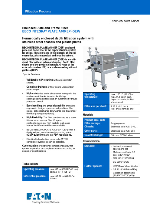
Technical Data Sheet Enclosed Plate and Frame FilterBECO INTEGRA® PLATE A400 EP (OEP)Hermetically enclosed depth filtration system withstainless steel chassis and plastic platesBECO INTEGRA PLATE A400 EP (OEP)-enclosedplate and frame filter is the depth filtration systemfor critical filtration tasks in the biotech, chemical,cosmetics, pharmaceutical and food industries.BECO INTEGRA PLATE A400 EP (OEP)-is a multi-sheet filter with an external chamber. Depth filtersheets seal the product channels. O-rings at theexternal chamber (EP) or a surface sealing withoutgaskets (OEP).Special Features-Validatable CIP cleaning without depth filtersheets.-Complete drainage of filter due to unique filterplate design.-High safety due to the absence of leakage in the environment thanks to a circular O-ringsealing/sealing surface and an automatic hydraulic pressure control.-Easy handling and good cleanability thanks to ergonomic design, open support profile of filterplates; cake discharge downwards into tray under the filter package (optional).-High flexibility: The filter can be used as a sheet filter or as a pre-coat filter. For pre-coating/removing of high particle load, cakeframes in different widths are available.-BECO INTEGRA PLATE A400 EP (OEP)-filter is designed and manufactured according to thecGMP guidelines and the FDA regulations.-Electrical (standard) or pneumatic (ATEX compliant) hydraulics can be selected. Customization or additional components allow for system expansion or complete systems according to customer specifications.Technical DataOperatingtemperature:max. 185 °F (85 °C) atmax.14,5 psi (1 bar),depends on depth filtersheets usedFilter area per sheet: 1.18 ft² (0,11 m²)(filer sheet format: 340) MaterialsProduct cont. partsFilter package:Chassis:PolypropyleneStainless steel AISI 316L Other parts: Stainless steel AISI 304 Gaskets/O-rings: Silicone, EPDM, Viton DocumentationStandard: -Instruction manual/spare parts list-Material certificate 3.1acc. to EN 10204-FDA / EU 1935/2004-CE 2006/42/EGFurther options: -USP Class VI certificates-CE 2014/34/EG (ATEX)-Validation documents(FS/FAT/SAT/IQ/OQ)Type Filter area Cakevolume * ChassissizeFilter plates/cake framesDepth filtersheets14.84 x 15.75 in377 x 400 mmWeightft² (m²) gal (l) qty. qty. lb (kg)A400 SF 11.84 1,1023.68 2,2044.99 4,1868.67 6,38 ----12344/59/1018/1928/29102038581070 (485)1213 (550)1440 (653)1661 (753)A400 ASF with 15 mm cake frames 16.58 1,5430.78 2,8654.47 5,0682.88 7,702.03 7,703.78 14,306.68 25,3010.17 38,5012346/712/1322/2334/35142646701072 (486)1204 (546)1405 (637)1605 (728)A400 ASF with 20 mm cake frames 14.21 1,3226.05 2,4249.73 4,6275.78 7,042.62 9,904.79 18,159.15 34,6513.95 52,8012345/610/1120/2131/32122242641061 (481)1184 (537)1387 (629)1579 (716)A400 ASF with 25 mm cake frames 11.84 1,1023.68 2,2044.99 4,1868.67 6,382.91 11,005.81 22,0011.04 41,8016.85 63,8012344/59/1018/1928/29102038581054 (478)1182 (536)1381 (626)1570 (712)A400 ASF with 30 mm cake frames 11.84 1,1021.31 1,9842.63 3,9663.94 5,943.63 13,756.54 24,7512.35 46,7519.61 74,2512344/58/917/1826/27101836541059 (480)1178 (534)1385 (628)1570 (712)A400 ASF with 40 mm cake frames 9.47 0,8818.94 1,7635,52 3,3054.47 5,064.07 15,408.14 30,8015.82 59,9023.39 88,5512343/47/814/1522/2381630461054 (478)1180 (535)1374 (623)1564 (709)* usable cake volumeFilter Plates/Cake framesWidth Cakevolume*Weightin (mm) gal (l) lb (kg) Filter plate 0.98 25 7.71 3,5 Cake frame 0.98 25 7.71 3,5 Cake frame 0.59 15 0.30 1,10 3.35 1,6 Cake frame 0.79 20 0.44 1,65 3.75 1,7 Cake frame 0.98 25 0.58 2,20 4.63 2,1 Cake frame 1.18 30 0.73 2,75 5.51 2,5 Cake frame 1.57 40 1.02 3,85 7.50 3,4 * usable cake volumeFilter plate (EP) ConnectionsFilter inlet: 1“Tri-Clamp ASME BPE" Filter outlet: 1“Tri-Clamp ASME BPE" External chamber: ½“Tri-Clamp ASME BPE Other designsRound thread connection according to DIN 11851, sterile flange, tri-clamp or according to customer requirementsCake frameDimensionsChassis size 1 61.38 (1559) 21.34 (542) 18.11 (460) 33.15 (842) Chassis size 2 75.31 (1913) 35.28 (896) 18.11(460)47,09(1196) Chassis size 3 95.16 (2417) 55.12 (1400) 23.62 (600) 66.93 (1700) Chassis size 4121.85 (3095)77.13 (1959)23.62 (600)88.94 (2259)North America44 Apple StreetTinton Falls, NJ 07724Toll Free: 800 656-3344(North America only)Tel: +1 732 212-4700Europe/Africa/Middle EastAuf der Heide 253947 Nettersheim, Germany Tel: +49 2486 809-0Friedensstraße 4168804 Altlußheim, Germany Tel: +49 6205 2094-0An den Nahewiesen 2455450 Langenlonsheim, Germany Tel: +49 6704 204-0 ChinaNo. 3, Lane 280,Linhong RoadChangning District, 200335Shanghai, P.R. ChinaTel: +86 21 5200-0099Singapore100G Pasir Panjang Road #07-08Singapore 118523Tel: +65 6825-1668For more information, pleaseemail us at ********************or visit /filtration© 2021 Eaton. All rights reserved. All trademarks andregistered trademarks are the property of their respectiveowners. All information and recommendations appearingin this brochure concerning the use of products describedherein are based on tests believed to be reliable.However, it is the user’s responsibility to determine thesuitability for his own use of such products. Since theactual use by others is beyond our control, no guarantee,expressed or implied, is made by Eaton as to the effects ofsuch use or the results to be obtained. Eaton assumes noliability arising out of the use by others of such products.Nor is the information herein to be construed as absolutelycomplete, since additional information may be necessaryor desirable when particular or exceptional conditions orcircumstances exist or because of applicable laws orgovernment regulations.ENA 2.6.11.1101-2021。
ARTISAN TECHNOLOGY GROUP 质量二手设备来源说明书

Agilent N4237ADDR2 DRAM BGA ProbeUser’s GuideNotices© Agilent Technologies, Inc. 2005No part of this manual may be reproduced in any form or by any means (including electronic storage and retrieval or translation into a foreign language) without prior agreement and written consent from Agilent Technologies, Inc. as governed by United States and international copyright laws.Manual Part NumberN4237-97000Print HistoryN4237-97000, September 2005Printed in USAAgilent Technologies, Inc.1900 Garden of the Gods RoadColorado Springs, CO 80907 USATrademark Acknowledgements WarrantyThe material contained in this document isprovided “as is,” and is subject to beingchanged, without notice, in future editions.Further, to the maximum extent permitted byapplicable law, Agilent disclaims allwarranties, either express or implied, withregard to this manual and any informationcontained herein, including but not limited tothe implied warranties of merchantability andfitness for a particular purpose. Agilent shallnot be liable for errors or for incidental orconsequential damages in connection withthe furnishing, use, or performance of thisdocument or of any information containedherein. Should Agilent and the user have aseparate written agreement with warrantyterms covering the material in this documentthat conflict with these terms, the warrantyterms in the separate agreement shallcontrol.Technology LicensesThe hardware and/or software described inthis document are furnished under a licenseand may be used or copied only in accordancewith the terms of such license.Restricted Rights LegendIf software is for use in the performance of aU.S. Government prime contract orsubcontract, Software is delivered and licensedas “Commercial computer software” asdefined in DFAR 252.227-7014 (June 1995), oras a “commercial item” as defined in FAR2.101(a) or as “Restricted computer software”as defined in FAR 52.227-19 (June 1987) or anyequivalent agency regulation or contractclause. Use, duplication or disclosure ofSoftware is subject to Agilent Technologies’standard commercial license terms, and non-DOD Departments and Agencies of the U.S.Government will receive no greater thanRestricted Rights as defined in FAR 52.227-19(c)(1-2) (June 1987). U.S. Government userswill receive no greater than Limited Rights asdefined in FAR 52.227-14 (June 1987) or DFAR252.227-7015 (b)(2) (November 1995), asapplicable in any technical data.Safety NoticesA CAUTION notice denotes ahazard. It calls attention to anoperating procedure, practice, orthe like that, if not correctlyperformed or adhered to, couldresult in damage to the product orloss of important data. Do notproceed beyond a CAUTION noticeuntil the indicated conditions arefully understood and met.A WARNING notice denotes ahazard. It calls attention to anoperating procedure, practice, orthe like that, if not correctlyperformed or adhered to, couldresult in personal injury or death.Do not proceed beyond aWARNING notice until theindicated conditions are fullyunderstood and met.IntroductionIntroduction—4N4237A DDR2 DRAM BGA Probe Description—5Fixture Technical Feature Summary—5Equipment Supplied—6DDR2 DRAM BGA probe Operation—7Installing the Probe—7Connecting test equipment to the N4237A probe—8Logic Analyzer connection to the N4237A—9Logic Analyzer configuration file setup with the N4237A—11 Characteristics, Regulatory, and Safety Information—11Operating Characteristics—11Safety Notices—11Warnings—11Safety Symbols—12IntroductionIntroductionThis User's Guide provides operation and programming informationfor the N4237A DDR2 DRAM BGA probe. This information alsoapplies to the N4239A probe, which comes without the flying leads.The illustrations below show the overall features and connectionpoints for the probe:N4237A DDR2 DRAM BGA Probe Description N4237A DDR2 DRAM BGA Probe DescriptionThe N4237A DDR2 DRAM BGA probe enables logic analyzer state andtiming measurements of the DQ, DQS, and clock signals of x4 and x8DRAMs using the JEDEC standard common DDR2 DRAM footprint.The N4237A probe interposes between the DRAM being probed andthe PC board where the DRAM would normally be soldered. It isdesigned to be soldered to the PCB footprint for the DRAM and theDRAM being probed is then soldered to the top side of the probe.Each DRAM signal in the common footprint (including those definedfor x16 DRAMS) passes directly from the bottom side of the probe tothe top side of the probe. Buried probe resistors placed at the DRAMballs connect the probed signals to 0.050” headers designed to matewith Agilent E5381A differential flying lead probes. These resistorsminimize capacitive loading on the DRAM signals and allow highspeed operation.The 0.050” headers on the N4237A probe are also compatible withthe Agilent InfiniMax oscilloscope probes. This allows low load scopeprobing of the DRAM signals.Fixture Technical Feature SummaryProbing of DDR2 x4 and x8 DRAMS in BGA package using JEDECstandard common BGA footprint.Logic analyzer (using E5381A differential flying leads) andoscilloscope (using InfiniMax socketed probe head) connection toDQ0-7, DQS, DQS#, and CK/CK# signals.Pass through of all signals for x16 support x16 operation whileprobing the lower-byte signals.Differential or single ended probing of DQS and CLK signals.Interposer design probes signals between DRAM BGA balls andDIMM.Probe height profile avoids interference with decouplingcapacitors on top of FB-DIMM boards.Use of separate flying lead probes for connection to the logicanalyzer optimizes use of analyzer channels by allowingassignment of analyzer channels to 4 or 8 bits on each DRAM.Tin plating of the DRAM footprint on the top side of the probe iscompatible with leaded and no-lead DRAM balls.N4237A DDR2 DRAM BGA Probe DescriptionEquipment SuppliedN4237AThe following components have been shipped with your N4237Afixture:Nine N4237-66401 DDR2 DRAM BGA probesE5381A-61601 differential flying lead probe setThis User's GuideN4239AThe following components have been shipped with your N4239Afixture:Nine N4237-66401 DDR2 DRAM BGA probesThis User's GuidePart numbers are subject to change without notice.DDR2 DRAM BGA probe OperationDDR2 DRAM BGA probe OperationInstalling the ProbeThe N4237A probe is installed by soldering it to the BGA footprint ona PC Board where the DRAM would normally be soldered. TheDRAM to be probed may then be soldered to the top side of theprobe. The bottom side of the N4237A has lead-free solder balls thatcorrespond to the solder balls on a normal DRAM. Therefore, lead-free temperature profiles must be used to solder the probe. Thissoldering is usually done at a BGA rework station. Due to widevariations in the type of rework stations a standard procedurecannot be defined. However, some general guidelines can be given:The center of gravity of the probe is not the same as it is for aDRAM (which is usually the center of the package). This is due tothe location and weight of the headers that connect to the logicanalyzer or scope. When soldering the probe, it is usuallynecessary to support the top end of the probe (under theheaders) to keep the probe flat against the surface of the DIMM.This may be as simple as a small piece of 50 mil PCB placedunder the headers.When soldering the DRAM onto the probe the temperature mayneed to rise to the point where the solder balls under the probesoften. A means of holding the probe in place when soldering theDRAM may be necessary.Normal surface cleaning and preparation procedures for BGAsoldering are recommended.DDR2 DRAM BGA probe OperationConnecting test equipment to the N4237A probeTwelve 0.050” headers are provided on the N4237A to allowconnection to a logic analyzer or oscilloscope probe. One header isprovided for each of the following signals: DQ[0:7], DQS, DQS#, CLK,CLK#. The layout of these headers is shown below (top view):DDR2 DRAM BGA probe OperationLogic Analyzer connection to the N4237AThe E5381A differential flying lead set supplied with the N4237A isused to connect the probe to the logic analyzer. The E5281A plugsinto any desired logic analyzer pod cable, and the flying leads pluginto the N4237A headers as shown below:When plugging into adjacent headers on the N4237A the heat shrinktubing sleeves around the connector body at the end of eachdifferential flying lead may force a tight fit. If this occurs, the portionof the sleeve around the connector body may be trimmed. This willallow connection to adjacent headers without interference. Be sureto not trim away the heat shrink tubing from the flying lead areaabove the actual connector body.DDR2 DRAM BGA probe OperationNote that the orientation of the DQS/DQS# and CLK/CLK# headers issuch that these signals can be probed differentially or as a pair ofsingle ended signals. To probe these signals as single ended pairs,the scope or logic analyzer probe should be plugged into the probe asshown in the diagram below:To probe differentially, plug the logic analyzer or scope leads asshown below:10 DDR2 DRAM BGA Probe User’s GuideArtisan Technology Group - Quality Instrumentation ... Guaranteed | (888) 88-SOURCE | Characteristics, Regulatory, and Safety InformationDDR2 DRAM BGA Probe User’s Guide11 Logic Analyzer configuration file setup with the N4237ABecause the mapping of specific RAM signals on specific DRAMS toeach logic analyzer channel depends on which DRAMS on a DIMMare probed and how the flying leads are arranged when connecting tothe N4237A, there is no single logic analyzer configuration file setup.For example, when probing x4 DRAMS, only four analyzer channelswill be connected to each DRAM. The logic analyzer Buses/Signalssetup dialog will allow you to assign descriptive labels to eachanalyzer channel that associate each channel with the particularDRAM and DRAM signal being probed.Characteristics, Regulatory, and Safety InformationOperating CharacteristicsThe following operating characteristics are not specifications, but aretypical operating characteristics for the analysis probe withinterposer.Table 1 Environmental Characteristics (Operating) Temperature20° to + 30° C (+68° to +86° F) Altitude4,600 m (15,000 ft) Humidity Up to 50% noncondensing. Avoid sudden, extreme temperature changes which could cause condensation on the circuit board. For indoor use only.Table 2 Inputs and Outputs To probeMemory bus signals from target system From probe High-density connectors for an Agilent 16700- or 16900-series logic analysis system.Safety NoticesThis apparatus has been designed and tested in accordance with IECPublication 1010, Safety Requirements for Measuring Apparatus, andhas been supplied in a safe condition. Before applying power, verifythat the correct safety precautions are taken (see the followingwarnings). In addition, note the external markings on the instrumentthat are described under "Safety Symbols."WarningsUse only the recommended power supply.Artisan Technology Group - Quality Instrumentation ... Guaranteed | (888) 88-SOURCE | Safety Notices12 DDR2 DRAM BGA Probe User’s GuideIf you energize this instrument by an auto transformer (for voltagereduction or mains isolation), the common terminal must beconnected to the earth terminal of the power source.Whenever it is likely that the ground protection is impaired, youmust make the instrument inoperative and secure it against anyunintended operation.Service instructions are for trained service personnel. To avoiddangerous electric shock, do not perform any service unless qualifiedto do so. Do not attempt internal service or adjustment unlessanother person, capable of rendering first aid and resuscitation, ispresent.Do not install substitute parts or perform any unauthorizedmodification to the instrument.Capacitors inside the instrument may retain a charge even if theinstrument is disconnected from its source of supply.Do not operate the instrument in the presence of flammable gasses orfumes. Operation of any electrical instrument in such anenvironment constitutes a definite safety hazard.Do not use the instrument in a manner not specified by themanufacturer.To clean the instrumentDo not attempt to clean this product. Safety Symbols! Instruction manual symbol: the product is marked with this symbol when it is necessary for you to refer to the instruction manual in order to protect against damage to the product. Hazardous voltage symbol.Earth terminal symbol: Used to indicate a circuit common connected to grounded chassis.Artisan Technology Group - Quality Instrumentation ... Guaranteed | (888) 88-SOURCE | 。
Artisan Technology Group 产品说明书

Agilent Technologies355C, D, E, FVHF AttenuatorsOperating and ServiceManualAgilent Part Number: 00355-90051Printed in USAApril 2002Supersedes: November 2001NoticeThe information contained in this document is subject to change without notice.Agilent Technologies makes no warranty of any kind with regard to this material, including, but not limited to, the implied warranties of merchantability and fitness for a particular purpose. Agilent Technologies shall not be liable for errors contained herein or for incidental or consequential damages in connection with the furnishing, performance, or use of this material.Agilent Technologies assumes no responsibility for the use or reliability of its software on equipment that is not furnished by Agilent Technologies. This document contains proprietary information which is protected by copyright. All rights are reserved. No part of this document may be photocopied, reproduced, or translated to another language without prior written consent of Agilent Technologies.Restricted Rights LegendUse, duplication, or disclosure by the U.S. Government is subject to restrictions as set forth in subparagraph (c)(1)(ii) of the Rights in Technical Data and Computer Software clause at DFARS 252.227-7013 for DOD agencies, and subparagraphs (c)(1) and (c)(2) of the Commercial Computer Software Restricted Rights clause at FAR 52.227-19 for other agencies. Serial Number PrefixThe specifications in this manual apply to the instruments with the following serial numbers or greater:Model Serial Numbers (min.)355C2524A44630355D2522A46649355E1205A38159355F1203A03244© Copyright 1997, 2001, 2002Agilent Technologies, Incii VHF Attenuators Operating and Service ManualWhat You’ll Find in This Manual…This operating and service manual contains the following:•Instrument Description and Specifications•Replaceable Parts and Accessories•Installation Instructions•Operating Instructions•Schematics and DiagramsWarrantyCustom systems are warranted by contractual agreement between AgilentTechnologies and the Customer.Certification Agilent Technologies certifies that this product met its published specifications at the time ofshipment from the factory.Documentation Warranty THE MATERIAL CONTAINED IN THIS DOCUMENT IS PROVIDED "AS IS," AND IS SUBJECT TO BEING CHANGED, WITHOUT NOTICE, IN FUTURE EDITIONS. FURTHER, TO THE MAXIMUM EXTENT PERMITTED BY APPLICABLE LAW, AGILENT DISCLAIMS ALL WARRANTIES,EITHER EXPRESS OR IMPLIED WITH REGARD TO THIS MANUAL AND ANY INFORMATION CONTAINED HEREIN,INCLUDING BUT NOT LIMITED TO THE IMPLIED WARRANTIES OF MERCHANTABILITY AND FITNESS FOR A PARTICULAR PURPOSE. AGILENT SHALL NOT BE LIABLE FOR ERRORS OR FOR INCIDENTAL OR CONSEQUENTIAL DAMAGES IN CONNECTION WITH THE FURNISHING, USE, OR PERFORMANCE OF THIS DOCUMENT OR ANY INFORMATION CONTAINED HEREIN. SHOULD AGILENT AND THE USER HAVE A SEPARATE WRITTEN AGREEMENT WITH WARRANTY TERMS COVERING THE MATERIAL IN THIS DOCUMENT THAT CONFLICT WITH THESE TERMS, THE WARRANTY TERMS IN THE SEPARATE AGREEMENT WILL CONTROL.VHF Attenuators Operating and Service Manual iiiAssistance Product maintenance agreements and other customer assistance agreementsare available for Agilent Technologies products.For assistance,call your local Agilent Technologies Sales and Service Office(refer to“Support and Service”).Support and ServiceAny adjustment, maintenance, or repair of this product must be performedby qualified personnel. contact your local Agilent Technologies sales andservice office.Online assistance:/find/assistUnited States (tel)180****4844Latin America(tel) (305) 269 7500(fax) (305) 269 7599Canada(tel)187****4414(fax) (905) 282-6495New Zealand (tel) 0 800 738 378 (fax) (+64) 4 495 8950Japan(tel) (+81) 426 56 7832(fax) (+81) 426 56 7840Australia(tel) 1 800 629 485(fax) (+61) 3 9210 5947Malaysia(tel) 1 800 828 848 (fax) 1 800 801 664Philippines(tel) (632) 8426802(tel) (PLDT subscriber only):1 800 16510170(fax) (632) 8426809(fax) (PLDT subscriber only):1 800 16510288Thailand(tel) outside Bangkok:(088) 226 008(tel) within Bangkok:(662) 661 3999(fax) (66) 1 661 3714Taiwan(tel) 0800-047-866 (fax) (886) 2 25456723People’s Republic of China(tel) (preferred): 800-810-0189(tel) (alternate):10800-650-0021(fax) 10800-650-0121India(tel) 1-600-11-2929(fax) 000-800-650-1101iv VHF Attenuators Operating and Service ManualVHF Attenuators Operating and Service Manual vSafety and Regulatory InformationReview this product and related documentation to familiarize yourself withsafety markings and instructions before you operate the instrument Thisproduct has been designed and tested in accordance with international standards.WARNING The WARNING notice denotes a hazard. It calls attention to a procedure,practice,or the like,that,if not correctly performed or adhered to,could result in personal injury. Do not proceed beyond a WARNING notice until the indicated conditions are fully understood and met.CAUTION The CAUTION notice denotes a hazard. It calls attention to an operatingprocedure,practice,or the like,which,if not correctly performed or adheredto, could result in damage to the product or loss of important data. Do notproceed beyond a CAUTION notice until the indicated conditions are fullyunderstood and met.Instrument MarkingsWhen you see this symbol on your instrument, you should refer to the instrument’s instruction manual for important information.This symbol indicates hazardous voltages.The laser radiation symbol is marked on products that have a laser output.This symbol indicates that the instrument requires alternating current (ac) input.The CE mark is a registered trademark of the European Community. If it isaccompanied by a year, it indicates the year the design was proven.The CSA mark is a registered trademark of the Canadian Standards Association.1SM1-A This text indicates that the instruments an Industrial Scientific and Medical Group 1Class A product (CISPER 11, Clause 4).This ISM device complies with Canadian ICES-001.Cet appareil ISM est conforme a la norme NMB du Canada.This symbol indicates that the power line switch is ON.This symbol indicates that the power line switch is OFF or in STANDBY position.!Safety Earth Ground This is a Safety Class I product (provided with a protective earthing terminal).An uninterruptible safety earth ground must be provided from the main power source to the product input wiring terminals, power cord, or supplied power cord set. Whenever it is likely that the protection has been impaired, the product must be made inoperative and secured against any unintended operation.Before Applying Power Verify that the product is configured to match the available main powersource as described in the input power configuration instructions in thismanual. If this product is to be powered by autotransformer, make sure thecommon terminal is connected to the neutral(grounded)side of the ac powersupply.vi VHF Attenuators Operating and Service ManualTypeface ConventionsItalics•Used to emphasize important information:Use this software only with the xxxxxX system.•Used for the title of a publication:Refer to the xxxxxX System-Level User’s Guide.•Used to indicate a variable:Type LOAD BIN filename.Instrument Display•Used to show on-screen prompts and messages that you will see on thedisplay of an instrument:The xxxxxX will display the message CAL1 SAVED.[Keycap]•Used for labeled keys on the front panel of an instrument or on acomputer keyboard:Press[Return].{Softkey}•Used for simulated keys that appear on an instrument display:Press{Prior Menu}.User Entry•Used to indicate text that you will enter using the computer keyboard;text shown in this typeface must be typed exactly as printed:Type LOAD PARMFILE•Used for examples of programming code:#endif // ifndef NO_CLASSPath Name•Used for a subdirectory name or file path:Edit the file usr/local/bin/sample.txtComputer Display•Used to show messages, prompts, and window labels that appear on acomputer monitor:The Edit Parameters window will appear on the screen.•Used for menus, lists, dialog boxes, and button boxes on a computermonitor from which you make selections using the mouse or keyboard:Double-click EXIT to quit the program.VHF Attenuators Operating and Service Manual viiTypeface Conventionsviii VHF Attenuators Operating and Service ManualGeneral InformationGeneral InformationThis manual contains operating instructions for 355C, 355D, 355E, and355F VHF Attenuators. Included in the manual is the information requiredto install and test these attenuators.Description The Agilent Technologies Model 355C, 355D, 355E, and 355F attenuatorsare50-ohm,coaxial step attenuators usable from dc to1GHz.Models355Cand 355E provide 0 to 12 dB of attenuation in 1 dB steps.Models 355D and 355F provide 0 to 120 dB of attenuation in 10 dB steps.The 355C and 355D are manual attenuators. The 355E and 355F areprogrammable. The schematic for the Model 355C/D is shown in Figure1,and that of the Model 355E/F in Figure2.The attenuator sections consist of resistor pi networks which are switched inor bypassed by microswitches. In the 355C and 355D, the microswitchesare actuated by cams (see Figure1). In the 355E and 355F, themicroswitches are actuated by solenoids (see Figure2). The standard RFconnectors are BNC type.In the355E and355F,power must be continuously applied to the solenoid toactuate the microswitch(i.e.,to insert an attenuator section).Each solenoiddraws approximately at 15 Vdc.Dimensions for the individual instruments are provided in Table1,“Dimensions,” on page2.VHF Attenuators Operating and Service Manual1General InformationNOTE Dimensions are for general information only. If accurate dimensions arerequired for building special enclosures, contact your nearest AgilentTechnologies office.Table 1Dimensions355C, D355E, FLength152 mm (5.98 in)137 mm (5.39 in)Height69 mm (2.72 in)72 mm (2.83 in)Width (without RF connectors)45 mm (1.77 in)45 mm (1.77 in)Width (with connectors):Standard (BNC) Option 001 (Type-N) Option 005 (TNC)73 mm (2.88 in)94 mm (3.70 in)69 mm (2.72 in)73 mm (2.88 in)121 mm (4.76 in)24 mm (0.94 in)Protrusion of connectors:BNC Type-N TNC 14.06 mm (0.55 in)24.5 mm (1.00 in)12 mm (0.47 in)14.06 mm (0.55 in)24.5 mm (1.00 in)12 mm (0.47 in)General InformationFigure 1355C and 355D Schematic DiagramGeneral InformationFigure 2355E and 355F Schematic DiagramGeneral Information Specifications Instrument specifications are listed in Table2. These specifications are theperformance standards or limits against which the instruments may betested.Table 2SpecificationsMODELS 355C and 355EAttenuation Range0 to 12 dBAttenuation Steps 1 dBOverall Accuracy:at 1000 Hzdc to 500 MHz dc to 1000 MHz 0.1 dB 0.25 dB 0.35 dBMODELS 355D and 355FAttenuation Range0 to 120 dB Attenuation Steps10 dB Overall Accuracy:at 1000 Hz below 1000 MHz 0 to 120 dB 0.3 dB 0 to 90 dB 1.5 dB 90 to 120 dB 3 dBMODELS 355E and 355FSwitching Speed65 msRequired Solenoid Power+15 to +18 Vdc, 1/8 A MODELS 355C/E and 355D/FFrequency Range dc to 1000 MHz Impedance50 ohms (nominal) Maximum SWR (input and output):below 250 MHz below 500 MHz below 1000 MHz 1.2 1.3 1.5Maximum residual attenuation(insertion loss at 0 dB)0.20 dB + 2.30 dB/GHz Maximum power dissipation0.5W (average) Maximum pulse voltage350 Vpk 200sec ConnectorsStandard Option 001 Option 005BNC (female) Type-N (female) TNC (female)11. Available on the 355C only.General InformationPower RatingCAUTION Do not exceed the RF power rating of0.5W average,or2450W peak with amaximum pulse width of 200 s. Do not connect an attenuator RF input oroutput connector to greater than 5 Vdc. If the attenuator must be connectedto a device with a potential greater than 5 Vdc, use a blocking capacitor. Accessories Supplied The 355E and 355F programmable attenuators are supplied with a 7-pin,male connector (1251-1037) for the solenoid drive input.Attenuator Options Figure3on page7shows solenoid and connector wiring diagrams availableunder Option 007 for 355E and 355F.General Information Attenuator OptionsFigure 3355E and 355F Solenoid and Connector Wiring DiagramsInstallationInstallationInitial Inspection Inspect the shipping container for damage. If the shipping container orcushioning material is damaged, it should be kept until the contents of theshipment have been checked mechanically and electrically.A procedure forchecking electrical performance is given under“Operator’s Check” onpage9 (also see“Performance Tests” on page12). If the contents of theshipment are incomplete, if there is mechanical damage or defect, or if theinstrument does not pass the electrical performance test, notify the nearestAgilent Technologies office. Keep the shipping materials for the carrier'sinspection.Mating Connectors Mating RF input and output connectors used with the attenuators should be:•Standard . . . . . . . . . . . . . . . . . . . . . . . . . . . . . . . . . . . . . . . . . .Type BNC•Option 001 . . . . . . . . . . . . . . . . . . . . . . . . . . . . . . . . . . . . . . . . . .Type-N•Option 005 . . . . . . . . . . . . . . . . . . . . . . . . . . . . . . . . . . . . . . . .Type TNCFor the 355E and 355F, the solenoid drive connector plug is 7-pin maleconnector (1251-1037).Operating Environment The operating environment of the instrument should be within the following limitations:•Temperature . . . . . . . . . . . . . . . . . . . . . . . . . . . . . . . . . . . . .0˚ to +55 ˚C •Humidity . . . . . . . . . . . . . . . . . . . . . . . . . . . . . . . . . . . . . .<95% relative •Altitude. . . . . . . . . . . . . . . . . . . . . . . . . . . . . . . . . .<4,570 m (15,000 ft)Storage and Shipment EnvironmentThe instrument should be stored in a clean,dry environment.The followingenvironmental limitations apply to both storage and shipment:•Temperature. . . . . . . . . . . . . . . . . . . . . . . . . . . . . . . . . . . . . . . . .−40˚ C to +75 ˚C•Humidity . . . . . . . . . . . . . . . . . . . . . . . . . . . . . . . . . . . . .< 95% relative•Altitude. . . . . . . . . . . . . . . . . . . . . . . . . . . . . . . . . .< 7,620 m (25,000 ft)Original PackagingContainers and materials identical to original packaging are available fromAgilent Technologies. If the instrument is being returned to AgilentTechnologies, attach a tag indicating the type of service required, returnaddress, model number, and serial number. Also, mark the containerFRAGILE to assure careful handling. In any correspondence, refer to theinstrument by model number and full serial number.Operating InstructionsOperating InstructionsCAUTION Do not apply RF power greater than 0.5W average, or 2450W peak with amaximum pulse width of 200 s. If these limits are e xceeded, the attenuatormay be damaged.Either RF connector may be used as the input or output connector,except inthe case of the355D/F driven from a low impedance source.This is becausethe leaf switch (Figures 1 and 2) may be closed before the microswitchopens when the dial is switched from 50 dB to 60 dB. Should this occur, amomentary short is placed across the connector, inviting damage to eitherthe microswitch or the signal source. Therefore, if the signal source issubject to damage by a short,use the rear most connector for the input.(Thedial or solenoid connector is at the front of the attenuator.) This pads themomentary short with 50 dB of isolation. For the 355E and 355F, wire thesolenoid drive plug supplied using Figure 3 as a wiring guide. Anun-energized attenuator solenoid section is 0 dB. Apply +1 5 to +18 Vdc(with respect to pin H) to energize an attenuator solenoid. A programmingtable is also given in Figure 3.Operator’s Check This section describes the procedures for the operator to make a quick checkof the attenuator prior to use or if a failure is suspected.NOTE Troubleshooting consists of performing the following Operator's Check. Ifthe instrument does not perform within limits, return the instrument to thenearest Agilent Technologies office.DescriptionThe attenuator is driven from a 50-ohm signal source at 1 kHz. The outputlevel from the attenuator is detected by a narrow-bandwidth voltmeter (thatis,the SWR meter).The attenuator and detector range switches are steppedtogether and the variations in level noted. This verifies that each attenuatorsection is being properly switched and checks the low frequency accuracy ofthe attenuator.NOTE The SWR Meter used in this check is calibrated for a square-law detectorand therefore the range changes and errors (read in dB) are twice thatindicated by the meter.Operating InstructionsQuick-Check Procedures1.Connect equipment as shown in Figure4,with the Attenuator set to0dBattenuation.2.Set Test Oscillator to 0.3 Vrms at 1 kHz.3.Set the SWR Meter input to XTAL IMPED LOW and the range to 2 dB(expanded) for 355D or 355F or to 10 dB (with 0 dB expand) for 355C or 355E. Adjust its bandwidth to the center of the adjustment range.Fine tune oscillator frequency to obtain the maximum meter indication.4.Set attenuator and SWR meter range switch as listed in Figure 3, andverify that the SWR meter indicates within the limits shown.Figure 4 Operator’s Check SchematicOperating Instructions Table 3Operator’s ChecksOperating InstructionsPerformance Tests The attenuator can be tested to the accuracy of the specifications in Table1with an Automatic Network Analyzer or equivalent equipment of suitableaccuracy.If an Automatic Network Analyzer is available,test the attenuatorusing the procedures in the analyzer's operating manual. The 355E and355F attenuators must be programmed by a suitable circuit to provide thevarious values of attenuation (see Figure 3).AdjustmentsThe attenuators have no internal adjustments and should not be opened. Ifdefective, the attenuator should be returned to the nearest AgilentTechnologies office for repair.CAUTION The solenoids in the 355E and 355F have been precisely adjusted at thefactory. No attempt should be made to replace them except by factoryapproved service representatives. The operation of the attenuators will beunreliable if plungers are not kept with their proper solenoids. Do notinterchange or "swap" them.12VHF Attenuators Operating and Service ManualReplaceable PartsReplaceable PartsTable4 lists the replaceable parts which are the only parts that can bereplaced without access to the interior of the attenuator. For any partsneeding replacement that are not listed in Table4, return the instrument toAgilent Technologies.CAUTION Due to special fixtures necessary for assembly, do NOT attempt to replaceany parts not listed in Table4. If the instrument is opened, the warranty isvoid.Table 4Replaceable PartsDescription Part Number Quantity355CGlide (feet)0403-00264Dial Assembly0370-30701Dial Assembly (Option 003)00355-000011355DGlide (feet)0403-00264Dial Assembly0370-30711Dial Assembly (Option 003)00355-000021355E and FGlide (feet)0403-00264Connector (7-pin, male)1251-10371VHF Attenuators Operating and Service Manual13。
Parker生物科学领域密封设备产品介绍说明书

Sealing SolutionsMiniature Elastomer SealsParker is able to create high qualityand consistent biocompatibleParFab™ Extruded Profi lesParker offers a wide variety ofPTFE FlexiSeals®Our full line of spring energized PTFE lip seals are used on rod, Composite SealsParker’s composite seals are rubber-to-metal, or rubber-to-plastic customFDA and USP Class VI Seal CompoundsO -r i n g s / C u s t o m M o l d e dE x t r u d e d P r o fi l e sMaterialHardness(Shore A)ColorComments ETHYLENE PROPYLENE – materials with temperature range -70°F to 250°F X XE7001-6060Black FDA X E1028-7070Black FDA X X E7736-7070Black FDAXE3609-7070Black FDA, USP Class VI X E7925-7070Black FDAX EJ590-7070White FDA, USP Class VI X E7871-7575Black FDA XE7126-8080Black FDA FLUOROCARBON – materials with temperature range -15° to 400°FX V0680-7070Red FDA X X V7108-7070White FDA X V1274-8080Black FDA PERFLUORINATED – materials with temperature range -5° to 608°FX FF200-7575Black FDAX FF350-7575White FDA, USP Class VI X FF500-7575Black FDA X V8545-7575Black FDA X V8562-7575White FDA NITRILE - materials with temperature range -30° to 225°FX N1219-6060Black FDA X NJ253-7070Black FDA X N1220-7070Black FDA XN1069-7070Black FDA XN7068-7070Black FDA XN0508-7575Black FDA XN7219-8080Black FDA SILICONE - materials with temperature range -60° to 450°FXS0802-4040White FDA X S7577-40(1)40Translucent USP Class VI XS7317-4040Translucent FDA XS7442-4040Rust FDA XXS7561-4040White FDA X S7433-50(1)50White USP Class VI X S7489-50(1)50Translucent USP Class VI X S7318-5050White FDA X S7405-5050Translucent FDA X S7435-5050Rust FDA X S7469-5050Red FDAXS1538-5555Translucent FDA, USP Class VI X S7530-55(1)55Translucent USP Class VI X S7311-5555Rust FDA X S7396-5555White FDAXS0317-6060RustFDA, USP Class VIO -r i n g s / C u s t o m M o l d e dE x t r u d e dP r o fi l e sMaterial Hardness(Shore A)Color Comments SILICONE - materials with temperature range -60° to 450°F (continued) X S7490-60(1)60Translucent USP Class VI X S7349-6060Red FDA X S7350-6060Green FDA X S7351F-6060White FDA X S7354-6060Blue FDA X S7355-6060White FDA X S7359-6060Black FDA X S7413-6060Rust FDA X S7526-6060Yellow FDA X S1138-7070Rust FDA X S7387-70(1)70Translucent USP Class VI X S7492-70(1)70Translucent USP Class VI X S7314F-7070Black FDA X S7494-7070Red FDA X S7525-7070White FDA X S0355-7575Rust FDA X S7386F-7575White FDA X S7383-80(1)80White USP Class VI X S7300F-8080White FDA X S7309-8080Black FDA X S7313-8080Blue FDA X S7548-8080Blue FDA X S7568-8080Red FDA THERMOPLASTIC - materials with temperature range -76° to 275°FX J7976-4545Beige USP Class VI X J7976-5555Beige USP Class VIXJ7737-5555Black USP Class VI X J7969-5555Beige FDA X J7813-5555Black FDA X J7902-6464Beige USP Class VIXJ7974-6464Black USP Class VI X J7959-6464Beige FDA X J7967-6464Black FDA X J7876-7373Beige USP Class VIXJ7975-7373Black USP Class VI X J7267-7373Beige FDA X J7968-7373Black FDA X J7970-8080Beige FDAXJ7907-8787Beige USP Class VI X J7971-8787Beige FDA X J7977-40D 40(2)Beige USP Class VI X J7972-40D40(2)Beige FDA XJ7973-50D50(2)BeigeFDA(1) Platinum cured silicone rubber(2) Hardness of compound is Shore DYour Local Authorized Parker Distributor © 2007 Parker Hannifi n Corporation. Product names are trademarks or registered trademarks of their respective companies.PSG 5028 2.5 AMD 10/07Parker Hannifi n CorporationEngineered Materials Group6035 Parkland BoulevardCleveland, OH 44124phone800 C PARKER/emg。
艾瓦特芯片规格书

艾瓦特芯片规格书如下:一、产品概述艾瓦特芯片是专为高性能计算和人工智能应用设计的高端芯片。
它采用最先进的7纳米工艺制造,具有高性能、低功耗和低热量排放的特点。
艾瓦特芯片支持并行计算,可以高效处理大规模数据和算法,是提高计算性能的关键组件。
二、技术规格1. 工艺技术:7纳米工艺制造2. 核心数量:双核心3. 内存带宽:高达51.2GB/s4. 计算能力:强大的计算能力,适用于高性能计算和人工智能应用5. 能耗:低功耗设计,适合节能环保6. 热量排放:先进的散热技术,确保芯片在高负荷运行时稳定可靠7. 工作温度:工作温度范围宽广,适应各种环境和使用场景三、性能特点1. 高性能:艾瓦特芯片采用并行计算架构,可高效处理大规模数据和算法,提高计算性能。
2. 高效能比:在相同的计算任务下,艾瓦特芯片的性能比传统处理器高得多。
3. 节能环保:低功耗设计和先进的散热技术,确保芯片在长时间运行和高温环境下稳定可靠。
4. 兼容性:艾瓦特芯片兼容现有的软件和硬件系统,方便用户使用。
四、应用领域艾瓦特芯片适用于各种高性能计算和人工智能应用,如大数据分析、云计算、机器学习和深度学习等。
它能够为各种应用提供强大的计算能力,提高工作效率和性能比。
五、生产与品质艾瓦特芯片采用最先进的生产工艺,确保产品的高品质和高稳定性。
我们的质量控制流程严格遵循行业标准,从原料到成品进行全面检测,确保产品的性能和质量达到最高水平。
六、服务与支持我们提供全面的售后服务和技术支持,包括产品咨询、故障排除、解决方案提供等。
我们承诺在第一时间解决客户的问题,确保客户的利益和满意度。
以上就是艾瓦特芯片的规格书,我们致力于为客户提供高性能、稳定可靠的产品,帮助客户实现更高的计算性能和效率。
维克森公司产品目录说明书

8Catalog 9EM-TK-190-1Pneumatic Division Richland, MichiganDimensionsF16-02-000Particulate Filter F16SpecificationsFlow Capacity* 1/4 63.0 SCFM (29.7 dm 3/s) 3/8 74.1 SCFM (34.9 dm 3/s)1/280.4 SCFM (37.9 dm 3/s)Operating Plastic Bowl 32° to 125°F (0° to 52°C) Temperature Metal Bowl 32° to 150°F (0° to 65.5°C)Maximum Supply Plastic Bowl 150 PSIG (10.3 bar) Pressure Metal Bowl 200 PSIG (13.8 bar)Port SizeNPT / BSPP-G1/4, 3/8, 1/2Standard Filtration Micron5Useful Retention** oz. (cm 3) 2.7 (81)Weightlb. (kg)1.8 (0.8)* Inlet pressure 150 PSIG (10.3 bar). Pressure drop 5 PSID (0.3 bar).** Useful retention refers to volume below the quiet zone baffle.“F” Series Filters, Type “A” 5 micron elements: All Wilkerson Type “A” 5 micron elements meet or exceed ISO Class 3 for maximum particle size and concentration of solid contaminants.Materials of ConstructionBaffle PolypropyleneBodyZincBowls Plastic Bowl PolycarbonateMetal Bowl Zinc DeflectorPolypropyleneElement Retainer Acetal Filter ElementPolyethylene Seals Plastic BowlNitrileMetal Bowl Fluorocarbon Sight GaugeMetal BowlPolycarbonateFeatures• Manual Drain• 5 Micron Rated Element• Quick-disconnect Bowl Guard with Integral Plastic Bowl and Safety LatchAuto DrainManual DrainCatalog 9EM-TK-190-19Pneumatic Division Richland, MichiganOrdering InformationReplacement Bowl KitsMetal Bowl –Automatic Drain ...................................................FRP-95-950 Manual Drain .......................................................FRP-95-178Sight Gauge, Manual Drain.................................GRP-95-133Plastic Bowl –Bowl Guard, Automatic Drain ..............................FRP-95-015 Bowl Guard, Manual Drain ..................................FRP-95-014 Manual Drain .......................................................FRP-95-017Replacement Element KitsType “A”, 5 Micron ...................................................FRP-95-160AccessoriesAutomatic Drain, Nitrile .........................................GRP-95-973L-Bracket .................................................................GPA-95-016Manual Drain ...........................................................FRP-95-610Sight Gauge Kit ......................................................GRP-95-079123450.10.20.31051520250AIR FLOW RATEP R E S S U R E D R O Pb a rdm 3/s1234500.10.20.3P R E S S U R E D R O Pb a rAIR FLOW RATEdm 3/s012345P R E S S U R E D R O P10203040AIR FLOW RATEdm 3/s0.10.2b a r00.3Particulate Filter F16(Revised 5-4-07)。
细胞培养试剂和耗材-目录号

Millicell Probe Set
MilliCell细胞培养耗材
Milli 96 CULTURE PLATE 0.4um PCF 1 PK
MilliCell细胞培养耗材
Milli Stand Insrt 24 well PCF 12um 50/pk
MilliCell细胞培养耗材
MScn-IP Dura 0.45um Clr NS, 10/pk
Milli Stand Insrt .4um Organotypic 50/pk
MilliCell细胞培养耗材
Hang Culture 12 well PET 0.4um 48/pk
MilliCell细胞培养耗材
Milli Hang Culture 24 well PET 5um 48/pk
MilliCell细胞培养耗材
补充说明 50MM Millex过滤器 51MM Millex过滤器 52MM Millex过滤器 53MM Millex过滤器 54MM Millex过滤器 55MM Millex过滤器 56MM Millex过滤器 培养切片 培养切片 培养切片 培养切片
医学用Millex无菌滤器 医学用Millex无菌滤器 医学用Millex无菌滤器 医学用Millex无菌滤器 医学用Millex无菌滤器 医学用Millex无菌滤器 医学用Millex无菌滤器 医学用Millex无菌滤器 医学用Millex无菌滤器 医学用Millex Express无菌滤器 医学用Millex Express无菌滤器 医学用Millex Express无菌滤器 医学用Millex Express无菌滤器 医学用疏水Millex无菌滤器 医学用疏水Millex无菌滤器 医学用Millex无菌滤器 医学用Millex无菌滤器 医学用Millex无菌滤器 医学用Millex无菌滤器 医学用Millex无菌滤器 医学用Millex无菌滤器 医学用Millex无菌滤器 MilliCell细胞培养耗材 MilliCell细胞培养耗材 MilliCell细胞培养耗材 MilliCell细胞培养耗材 MilliCell细胞培养耗材 MilliCell细胞培养耗材 MilliCell细胞培养耗材 MilliCell细胞培养耗材 MilliCell细胞培养耗材 MilliCell细胞培养耗材 MilliCell细胞培养耗材 MilliCell细胞培养耗材 MilliCell细胞培养耗材
乾坤科技固定金属膜芯片抗性电阻器说明书
1/32W, 01005, Thick Film Chip Resistor (Lead / Halogen Free)1.ScopeThis specification applies to 0.2mm x 0.4mm (01005) size, fixed metal film chip resistors rectangular type for use in electronic equipment.2.Type DesignationXXX—X NHPFR02S —(2) (3)(4)(1)Where (1) Series No(2)Nominal resistance value:For example –Three digits of number (E-24 Series)000 = Jumper100 = 10Ω102 = 1kΩFour digits of number (E-96 Series)11R3 = 11.3Ω1131 =1.13kΩ(3)Tolerance of ResistanceF = ± 1.0%G = ± 2.0%J = ± 5.0%X = Jumper(Below 50 mΩ)(4)NH = Sn plating ( Lead free / Halogen free)b t6-2MechanicalSpecification and RequirementItemResistor JumperTest Method (Refer to JIS C 5201)Solderability The surface of terminal immersed shall beminimum of 95% covered with a newcoating of solder Solder bath:After immersing in flux, dip in245 ± 5 molten solder bath℃for 2 ± 0.5 secondsResistance to Solder HeatR:△ (1.0%+ 0.05Ω)Without distinctdeformation inappearanceMax. 50mΩ(1)Immersed at solder bathof 270 ± 5 for 10℃± 1 seconds(2)Measuring resistance1 hour after testVibration R:△ (0.5%+ 0.05Ω)Without mechanical damage such asbreak (1)Vibration frequency:10Hz to 55Hz in 60 secondsas a period(2)Vibration time: period cycledfor 2 hours in each of 3 mutualperpendicular directions (3)Amplitude: 1.5mmShock R:△ (0.25%+ 0.05Ω)Without mechanical damage such asbreak (1)Peak value: 490N(2)Duration of pulse: 11ms(3)3 times in each positive andnegative direction of 3 mutualperpendiculardirectionsBending Test R:△ (1.0%+ 0.05Ω)Without mechanical damage such asbreak Bending value: 3 mm for 30 ± 1 secondsSolvent Resistance Without mechanicaland distinct damagein appearance Max. 50mΩ(1)Solvent:Trichloroethaneor Isopropyl alcohol(2)Immersed in solvent atroom temperature for90 seconds6-3 EnduranceSpecification and RequirementItemJumper JumperTest Method (Refer to JIS C 5201)Rapid change of Temperature R: △ (1.0%+ 0.05Ω) Without distinct damagein appearance Max. 50m Ω (1) Repeat 5 cycle as follow: (-55 ± 3,30minutes) ℃→(Room temperature, 2~3minutes)→ (+125 ± 2,30minutes) ℃→(Room temperature, 2~3 minutes)(2) Measuring resistance 1 hour after testMoisture with Load R: △ (5.0%+ 0.1Ω) Without distinct damagein appearanceMarking should belegible Max. 50m Ω (1) Environment condition:40 ± 2,90~95% RH ℃ (2) Applied V oltage: rated voltage (3) Test period: (1.5 hour ON) →(0.5 hour OFF) cycled fortotal 1,000 + 48 / - 0 hours (4) Measuring resistance 1 hour after testLoad Life R: △ (5.0%+ 0.1Ω) Without distinct damagein appearanceMax. 100m Ω (1) Test temperature:70 ± 2 ℃ (2) Applied V oltage: rated V oltage(3) Test period: (1.5 hour ON)→(0.5 hour OFF) cycled for total 1,000 + 48 / - 0 hours (4) Measuring resistance 1 hour after testLow Temperature Store R: △ (5.0%+ 0.1Ω) Without distinct damagein appearanceMax. 100m Ω (1) Store temperature: -55 ± 3 for total ℃ 1,000 + 48 / - 0 hours (2) Measuring resistance 1 hour after testHigh Temperature Store R: △ (5.0%+ 0.1Ω) Without distinct damagein appearanceMax. 100m Ω (1) Store temperature: +125 ± 2 for total ℃ 1,000 + 48 / - 0 hours (2) Measuring resistance 1 hour after test9.Care note9-1Care note for storage(1)Chip resistor shall be stored in a room where temperature and humidity must be controlled.(temperature 5 to 35, hu℃midity 45 to 85% RH) However, a humidity keep it low, as it is possible.(2)Chip resistor shall be stored as direct sunshine doesn’t hit on it.(3)Chip resistor shall be stored with no moisture, dust, a material that will make solderabilityinferior, and a harmful gas (Chloridation hydrogen, sulfurous acid gas, and sulfurationhydrogen)9-2Care note for operating and handling(1)It is necessary to protect the edge and protection coat of resistors from mechanical stress.(2)Handle with care when printing circuit board (PCB) is divided or fixed on support body,because bending of printing circuit board (PCB) mounting will make mechanical stress forresistors.(3)Resistors shall be used with in rated range shown in specification. Especially, if voltage morethan specified value will be loaded to resistor, there is a case it will make damage formachine because of temperature rise depending on generating of heat, and increaseresistance value or breaks.(4)In case that resistor is loaded a rated voltage, it is necessary to confirms temperature of aresistor and to reduce a load power according to load reduction curve, because a temperaturerise of a resistor depends on influence of heat from mounting density and neighboringelement.(5)Observe Limiting element voltage and maximum overload voltage specified in eachspecification(6)If there is possibility that a large voltage (pulse voltage, shock voltage) charge to resistor, itis necessary that operating condition shall be set up before use.。
星制造国际有限公司产品说明书 - GR14系列
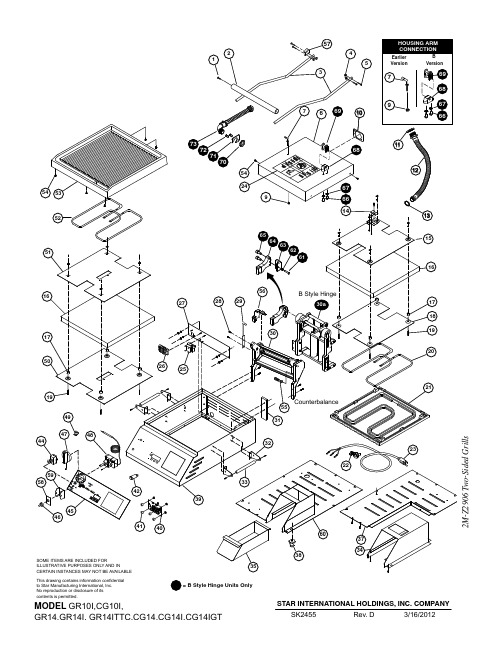
This drawing contains information confidential to Star Manufacturing International, Inc.IMPORTANT: WHEN ORDERING, SPECIFY VOLTAGE OR TYPE DESIREDPAGE 1 INCLUDE MODEL AND SERIAL NUMBER OF 4MODELPARTS LISTMarch 21, 2014, Rev. O14' TWO SIDED GRILLSFig. NoPart NoQtyDescriptionApplication12C-Z29922SCREW, HANDLE 22V-Z113951HANDLE, B-STYLE HINGECG142TB, CG14B, CG14E, CG14IB, CG14IGTB,CG14ITB, CG14ITGTB240, CG14ITLB, CG14ITSC,CG14TB, GR14B, GR14E, GR14IB, GR14ITB, GR14SNB, GR14TB2V-Z2989HANDLE - 14”, COUNTERBALANCE 2V-Z3413HANDLE - 14” S.S.GR14, GR14T, SER. # GRC00112 - 00138, GRC00778 - 00858, GRC00864 - 0125632B-Z113912ARM 14” SPT GR14SNB2B-Z2987ARM - 14”CG14EA, CG14IEA, GR14EA, GR14IEA, GR14C, CG14I, CG14IGT, CG14IT, CG14ITGT, GR14, GR14I, GR14IT 2B-Z3336ARMGR14SN2B-Z14019ARM, STANDARD 45 DEG.CG14DTB, CG14B, CG14E, CG14IB, CG14IT, GR14B, GR14E, GR14IB, GR14ITB42C-406374NUT 1/4-20 ACORN CAP MS ALL EXCEPT GR14SNB MODELS2C-08-07-0262WASHER52C-Z29924SCREW, ARM TO BRACKET2C-15234SCREW, .250-20UNC X .75 LG RHP B SERIES COUNTERBALANCE2C-08-07-0262LCKWSHR, .250 INTERLOCK TOOTH 6D9-Z20361HOUSING-TOP-14”D9-Z140201TOP HOUSING, LEFT, 14”CG142TB, CG14B, CG14E, CG14IB, CG14IGTB, CG14ITB, CG14ITGTB240, CG14ITLB, CG14ITSC,CG14TB, GR14B, GR14E, GR14IB, GR14ITB, GR14SNB, GR14TB72C-Z32002PIN - TOP HOUSING 82C-Z28552RETAINER RING92C-08-07-004021/4” NUT, USE PART NUMBER 2C-Z2820102A-Z38271PLATE, STAMPING - CONDUIT 112C-Z37802CONDUIT RETAINER 122E-Z28981CONDUIT ASSY. - PTFE 132E-Z37681CONDUIT LOCKNUT 14D9-04-GR-01661WIRE MOUNT15D9-GR00791TOP RETAINING PLATE AY/1416D9-Z28882INSULATION - 14”172A-Z66048SPACER - INSULATED PLATE 18D9-Z20751TOP ELEMENT/INS. PLATE/14192C-08-07-02858SCREW, ELEMENT RET. PLATE 20PS-Z19801ELEMNT REPL. KIT, 800W/120V CG14, CG14T, GR14, GR14IB GR14T, CG14IT-120V PS-Z2021ELEMNT REPL. KIT, 800W/240V CG14, CG14T, GR14, GR14TD9-GR0535ELEM\NT ASSY 800W/240V CG/GR14E-230V, CG/GR14E-240VPS-Z2391ELEMNT REPL, KIT, 1800W/240GR14I, GR14IT, CG14IGT, CG14ITGT, CG14I, CG14IT D9-GR0514ELEMENT, TOPCG14E-120V, GR14E-120V, GR14IE2M -Z 2906 T w o -S i d e d G r i l l sIMPORTANT: WHEN ORDERING, SPECIFY VOLTAGE OR TYPE DESIREDPAGE INCLUDE MODEL AND SERIAL NUMBEROF25MODELPARTS LISTMarch 21, 2014, Rev. O14' TWO SIDED GRILLS2M -Z 2906 T w o -S i d e d G r i l l sIMPORTANT: WHEN ORDERING, SPECIFY VOLTAGE OR TYPE DESIREDPAGEINCLUDE MODEL AND SERIAL NUMBER OF35MODELPARTS LISTMarch 21, 2014, Rev. O14' TWO SIDED GRILLSFig. NoPart NoQtyDescriptionApplication382A-Z14854FOOT, 1” ADJUSTABLE, 1/4” STUD CERTAIN APPLICATIONS 2A-Z11501FOOT, 1” SOLID RUBBER, 1/4” STUD ALLUMINUM PLATES2A-Z0314-1BASE, FOOT 4” CAST W/RUBBER FOOTCG14IB, CG14IGTB, CG14ITB, CG14ITLB, CG14ITSC, GR14IB, GR14ITB2A-Z12980 2.5” FOOT BASE, 3/8” STUD GR14I, GR14IT, CG14I, CG14IT, CG14IGT, CG14ITGT 2A-Z12946BASE, FOOT, NON-SKID CG14I, CG14IB, CG14IE, CG14IEGT, CG14IGTB, GR14I GR14IB, GR14IE, GR14ITB, (mfg after 4-2010) 39D9-GR00611BODY ASSY. - 14”D9-GR0184BODY ASSY GR14SN402J-Z18361TIMER CONTROL CG14T, CG14IT, CG14IGT, GR14T, GR14IT412K-Z19714SPACERCG14T, CG14IT, CG14IGT, CG14E, GR14T, GR14IT, GR14E,422J-Y66891PILOT LIGHT, 120V CG14, GR14 (120V MODELS)2J-Y6690PILOT LIGHT, 240V GR14I, CG14IGT, CG14I, CG14, GR14 (240V)44PS-GR02241RKER SWITCH RPL 14” KIT CG14T-120V W/SERIAL NO BELOW CGC25308CG14IT-120V W/SERIAL NO BELOW CGC24701GR14T-120V W/SERIAL NO BELOW GRC23789CG14IT-240V W/SERIAL NO BELOW CGC245592E-Z6863SWITCH 3 POS, DPDT CG14T, CG14IT, CG14IGT, GR14T, GR14IT 2E-Z3808SWITCH - 30A@120V CG14E-120V, GR14E-120V452M-Z30501OVERLAY - 14” NO TIMERGR14I, CG14IGT, CG14I, CG14, CG14B, GR14, GR14B, CG14GTB 2M-Z3816OVERLAY - 14” w/2 MANUAL TIMERS CG14-2T2M-Z3929OVERLAY, CHIPOTLE GR14SN, GR14SNB2M-Z6870OVERLAY - 14” w/TIMER GR14IT, CG14ITGT, CG14IT, CG14T, GR14T, GR14TB 2M-Z12002OVERLAYCG14E, GR14E 2M-Z18461LABEL ON & OFFCG14E, GR14E462I-05-07-00131RUBBER BOOT, SWITCH 472R-Z18541KNOB-CONTROL482T-64471THERMOSTAT 118V-236V 492A-Z30261HALF CLIP50D9-Z133381BTM. INSULATION RET. PLT. 14”51D9-Z133381BTM ELEMENT RET. PLATE 14”522N-Z19811BTM ELEMENT, HEATING, 1000W/120CG14, CG14T, GR14, GR14IB, GR14T, CG14IT-120V 2N-Z2022BTM ELEMENT, HEATING, 1000W/240CG14, CG14T, GR14, GR14T D9-GR0534BTM ELEMENT ASSY, 1000W/240GR14E-240V2N-Z2392BTM ELEMENT, HTG, 1800W/240V GR14I, GR14IT, CG14IGT, CG14ITGT, CG14I, CG14IT D9-GR0513BTM ELEMENT ASSYCG14E-120V, GR14E-120V, GR14IE 532F-Z19451CASTING, SM. BOT., ALUM.-14”GR14, GR14T, CG14GTB 2F-Z1947CASTING, GR. BOT., ALUM.-14”CG14, CG14T2F-Z1949CASTING, SM. BOT., IRON-14”GR14I, GR14IT, CG14IGT, CG14ITGT 2F-Z1951CASTING, GR. BOT., IRON-14”CG14I, CG14IT542C-Z58838SCREW 10-24X1/2 FZA 55PS-GR1342ROLLER BEARING KIT2M -Z 2906 T w o -S i d e d G r i l l sIMPORTANT: WHEN ORDERING, SPECIFY VOLTAGE OR TYPE DESIREDPAGE INCLUDE MODEL AND SERIAL NUMBEROF45MODELPARTS LISTMarch 21, 2014, Rev. O14' TWO SIDED GRILLS2M -Z 2906 T w o -S i d e d G r i l l sIMPORTANT: WHEN ORDERING, SPECIFY VOLTAGE OR TYPE DESIREDPAGE INCLUDE MODEL AND SERIAL NUMBEROF55MODELPARTS LISTMarch 21, 2014, Rev. O14' TWO SIDED GRILLSFig. NoPart NoQtyDescriptionApplicationNI 2R-09-WB-00062KNOB-BLACK (NOT SHOWN)CG14-2TNI2V-Z30272CROSS SUPPORT (NOT SHOWN)GR14I, GR14IT, CG14I, CG14IT, CG14IGT, CG14ITGT NI D9-GR01081FACEPLATE ASSY. - 14” NO TIMER GR14I, CG14IGT, CG14I, CG14, GR14NI D9-GR01781FACEPLATE ASSY. - 14” 2 TIMERS CG14-2T NI D9-GR01851FACEPLATE ASSY, - 14”GR14SNNI D9-GR02101FACEPLATE ASSY. - 14” w/TIMER GR14IT, CG14ITGT, CG14IT, CG14T, GR14T NI D9-Z120271PROBE BRACKET - BOTTOM CG14E, GR14ENI D9-Z30281SIDE SUPPORT (NOT SHOWN)GR14I, GR14IT, CG14I, CG14IT, CG14IGT, CG14ITGT NI D9-Z30291PART SUPPORT (NOT SHOWN)GR14I, GR14IT, CG14I, CG14IT, CG14IGT, CG14ITGT NIZ1-70-07-03431SWITCH GUARDCG14E, GR14E2M -Z 2906 T w o -S i d e d G r i l l s。
Agilent Cary UV-Vis Specifications 说明书

Cary SpectrophotometersCary spectrophotometers are manufactured according to a Quality system that is certified to the ISO-9001. The specifications listed below represent the average results of the final acceptance tests performed in the factory. With a sample of over six hundred Cary 50 instruments and over two thousand Cary 100 and 300 instruments, the specifications are indicative of the performance of Cary instruments. These specifications are not guaranteed. The guaranteed specifications are listed in a separate brochure and are based on the ±4 sigma statistical confidence level.Cary 50Dual beam, Czerny-Turner 0.28 m monochromator, 190–1100 nm wavelength range,approximately 1.5 nm fixed spectral bandwidth, full spectrum Xe pulse lamp single source with exceptionally long life, dual Si diode detectors, quartz overcoated optics, scan rates up to 24 000 nm/min, 80 data points per second maximum measurement rate, non measurement phase stepping wavelength drive, room light immunity, centrally controlled by PC with Windows interface.Cary 100/300Double beam, dual chopper, ratio recording, Czerny-Turner 0.28 monochromator UV-Visspectrophotometer, centrally controlled by a PC. Cary 300 has double dispersion, Cary 100 hassingle dispersion. High light throughput optical system with all reflective optical design, high speed accurate scanning. Optional centrally controlled accessory system. High performance R928photomultiplier tube, tungsten halogen visible source with quartz window, deuterium arc ultra violet source. Centrally controlled by PC with Windows interface.Cary 50Cary 100Cary 300Monochromator Czerny-Turner 0.28 m Czerny-Turner 0.28 m Czerny-Turner 0.28 m plus pre-monochromator Grating27.5 x 35 mm, 1200 lines/mm, 30 x 35 mm, 1200 lines/mm 30 x 35 mm, 1200 lines/mm blaze angle 8.6°at 240 nmblaze angle 8.6°at 240 nmblaze angle 8.6°at 240 nm Pre-monochromator:1200 lines/mm blaze angle 8.6°at 240 nm Beam Splitting System Beam splitterChopper (30 Hz) Chopper (30 Hz)Detectors2 silicon diode detectors R928 PMT R928 PMT UV-Vis Limiting Resolution (nm) <1.50.1890.193Tolune/Hexane Limiting Resolution test (nm) 1.65Stray Light (%T)At 200 nm(KCl EP/BP method)0.530.50 0.32At 220 nm(10 g/L NaI ASTM method)0.020.00740.00008At 370 nm(50 mg/L NaNO 2)0.0180.00130.000041Wavelength Range (nm)190-1100190-900190-900 Wavelength Accuracy (nm)0.07 at 541.92 nm 0.02 at 656.1 nm 0.02 at 656.1 nm 0.24 at 260.54 nm0.04 at 486.0 nm0.04 at 486.0 nm Wavelength Reproducibility (nm)0.01 0.0080.008Peak separation of repetitive scanning of a UV-Vis line source Spectral Bandwidth Accuracy (nm)At 0.20.1930.189At 2.02.032.03Photometric Accuracy (Abs)At 1 Abs (NIST filter method)0.0007At 0.3 Abs (Double Aperture method)0.000160.00016UV-VisCary 50, 100, 300SpectrophotometersTypicalSpecificationsCary 50Cary 100Cary 300Photometric Range(Abs) 3.3 3.7 5.0Photometric Display(Abs)±9.9999±9.9999±9.9999(%T)±200.00±200.00±200.00Photometric Reproducibility(Abs)At 465 nm At 590 nm, 2 nm SBW At 590 nm, 2 nm SBW Using NIST 930D filters, 2 secondSignal Averaging Time.Maximum deviation at 1 Abs0.004 <0.0008<0.0008Standard deviation for 10 measurements0.00050 <0.00016<0.00016At 546.1 nm At 546.1 nm, 2 nm SBW At 546.1 nm, 2 nm SBW2 second Signal Averaging TimeMaximum deviation at 0.5 Abs0.003 <0.0004<0.0004Standard deviation for 10 measurements0.00030 <0.00008<0.00008Photometric Stability(Abs/hour)30 minute warm up 2 hour warm up 2 hour warm up500 nm, 1 second Signal Averaging Time <0.0004<0.0003<0.0003Photometric Noise(Abs, RMS) 1.5 nm SBW 2 nm SBW 2 nm SBW500 nm, 1 second Signal Averaging Time.0.000063 at 0 Abs0.000030 at 0 Abs0.000030 at 0 Abs0.00014 at 1 Abs0.00014 at 3 Abs, 1.5 Abs RBA0.00025 at 3 Abs, 1.5 Abs RBA0.0018 at 2 Abs0.0022 at 5 Abs, 1.5 Abs RBA Baseline Flatness(Abs)200 to 850 nm, smooth 21 applied,baseline corrected 0.0006 0.000220.00025Sample CompartmentBeam Separation(mm)110110Compartment Size(Wx D xH) 130 x 523 x 123 mm139 x 389 x 129 mm139 x 389 x 129 mmNote that sample compartment Extended Sample Extended Samplecan be left open during Compartment fitted Compartment fittedmeasurement due to roomlight immunity of Cary 50Access Top and front Top and front Top and frontInstrument Dimensions(Wx D xH) 500 x 590 x 205 mm 640 x 650 x 320 mm 640 x 650 x 320 mm Purging None Sample compartment Sample compartment Instrument Weight21 kg45 kg45 kg Recommended environmental conditionsInstrument Storage5-45 °C at 20-80% relative humidity, non-condensing, altitude <2133 m.Instrument Operation Below 853 metres altitude: 10-35 °C, 8-80% relative humidity, non-condensing.Between 853 and 2133 metres altitude: 10-25 °C, 8-80% relative humidity, non-condensing. Instrument Electrical Requirements Instrument draws maximum of Mains supply of 100/120/220/240 volts AC ±10%, 50 or26 W of power from the host 60 Hz ±1 Hz with 400 VA power consumption.PC power supply. The powerrating is: +5 V DC <1A,+ 12 V DC <1.5 A, -12 V DC<0.25A. The Cary 50 interfacecard fits into a standard ISA slotin the host PC and requiresa standard PC internal Hard diskpower supply connector. Operationof motor driven accessories mayincrease the +12 V requirement bya further 2 A (24 W maximum).The host PC must be certified tostandard IEC 60950 or equivalent.OperationalCary 50Cary 100Cary 300Spectral Bandwidth (nm)Fixed at 1.5 nm 0.20-4.00 nm, 0.1 nm steps,0.20-4.00 nm, 0.1 nm steps, motor driven motor driven Signal Averaging (seconds)0.0125 to 999 0.033 to 9990.033 to 999Maximum Scan Rate (nm/min)24000(nm/min)/(cm-1/min*)/Å/min)3000/37046/300003000/37046/30000Maximum Slew Rate (nm/min)2400030003000(changing between wavelengths, nm/min)Data Interval (nm)0.15-5.00.02-1.670.02-1.67cm-1* 5.541-20.6 5.541-20.6Å0.2-16.70.2-16.7Data Collection Rate(kinetic studies) points per min per cell 1 cell 4800180018006 cells 55512 cells 35514 cells 3 to 4 3 to 418 cells26 cells, 0.0375 SAT 0.38 s Dwell time 40 to 5012 cells, 0.0375 SAT 0.38 s Dwell time 20 to 3018 cells, 0.0375 SAT 0.38 s Dwell time 10 to 206 cells, 0.033 SAT 0.34 s Dwell time 505012 cells, 0.033 SAT 0.34 s Dwell time 40 to 5040 to 5014 cells, 0.033 SAT 0.34 s Dwell time 30 to 4030 to 40Repetitive ScanningMaximum number of cycles 999999999Maximum cycle time (min)999999999Temperature MonitorsTemperature probe insideCell block, up toCell block, up tocuvette (using the Temperature 4 temperature probes inside 4 temperature probes inside Probe Accessory)cuvettes or elsewherecuvettes or elsewhereSoftware FunctionalityOperating SystemWindows® XP and Windows® 2000Graphical DisplayOptions available for the display • Data files can be retrieved with the associated Methods and all other settings.of data traces include:• Enhanced graphics control module with automatic peak labeling, grids, multiple line types, zoom, free and tracking cursor, multiple ordinate and abscissa formats, smart copy/paste and overlay modes for easy spectral interpretation, presentation and publication.• Graph labels and bitmaps, including chemical structures, can be displayed and saved with data files (fonts and size are selectable).File Opening • Files can be automatically opened by clicking on the file name. Files can be also be dragged and dropped into the application for easy opening.Data Conversion• Import: Cary OS/2, Cary DOS, ASCII XY formats.• Export: ASCII (*.csv format), ASCII with Audit log format.• Export data live to Excel or other compatible programs using Dynamic Data Exchange (DDE). File SystemMethod, Report, Data, Graphic template and files can be stored individually or all together in a batch file. The number of files is limited only by hard disk capacity.Fast Loading of Methods You can set up shortcut icons on the desktop for methods used frequently in your laboratory. Cursor ModesCross hair cursor in either tracking or free mode. Kinetics ruler mode also available.Running MultipleMore than one Cary application may be run at any time, allowing method development or data review Cary WinUV Applications and manipulation while the instrument is collecting. Either multiple same or different applications may be opened simultaneously.Built-in Programming LanguageApplications Development Language (ADL) allows complete customization of Cary Win UV to your specific applications. ADL can be used to create new user interfaces for the software – ideal for production and routine QC applications.Multimedia HelpComprehensive multimedia help includes instructional videos, animations and speech explaining how to set up the instrument and accessories and basic maintenance procedures.UV-VisCary 50, 100, 300SpectrophotometersTypicalSpecificationsQuantitative analysisCalibration Curve Fits Linear, Linear direct and Quadratic curves fits.Fibre Optics System Remote read fibre optics system for in-situ measurements using Dip Probe (measure up to 180 samples/hr). Sipper/Autosampler Support SPS-5 Autosampler supported for fibre optic and sipper measurements.Importing Sample Names Sample names can be imported in ASCII format from disk or LAN system.Calibration Standards Up to 30 standards.Maximum Number of Samples Up to 500 samples.Measurement Replicates Up to 5 replicates of each sample may be performed.Sample/Standard Averaging Up to 3 samples/standards can be averaged.User Specified Data Collection Single wavelength measurements with on-line calculations can be performed on data collectedusing +, -, /, x functions. .For example:• Abs 540 nm - Abs 700 nm• Abs 366 nm x factorWeight/Volume Correction You can correct concentration results for weight/volume differences between the sample and the nominalweight/volume in the method.Biochemical analysisData CommentsExtra information about the sample, The User Data Form allows entry of information about the samples analyzed, eg: pH, ionic, substrate and which is stored with the data file inhibitor concentration etc.Minimum sample volume The smallest volume of sample that can be measured accurately is approximately 2.5 µL.Preset methodsMethods for common measurements RNA/DNA application:that are built into the software• Protein estimation• Nucleic acid estimation• 260/280 ratio readings• Warburg & Christian co-efficientConcentration application:• Bradford• Lowry HS, LS• Biuret• BCA• Direct UVRNA/DNA Calculations User-selectable background correction, and Warburg Christian protein and nucleic acid factor entry. Biochemical analysis – KineticsCary 50Cary 100Cary 300Temperature Measurement Up to 2 temperature probes Measurement via a temperature probe built into the multicellcan be measured directly inside block. Additionally, up to 4 temperature probes can be measuredthe cuvettes with the optional directly inside the cuvettes with the optional TemperatureTemperature probe accessory.probe accessory.Number of Stages 5 different data collection rates can be specified. A different fit can be used for each stage.Kinetics Ruler To visually define the area of the data to be used for rate calculations, use the cursor to nominate therange for a point to point least squares slope calculation.Plot Fits Kinetic rate plots can be displayed with the data and stored.Fastest data collection ratefor single cells(points/sec)80 3030Stop time extension The time of the data collection can be extended without stopping the analysis.Min/Max data collection time0.01 to 8000 min 0.01 to 8000 min0.01 to 8000 minPause control Measurement can be paused to allow the addition of a reagent before continuing.Synchronized start A 2 minute countdown is provided before data collection begins.Cell loading guide A visual guide is provided to show how to load the multicell holder before starting the data collection. User specified data collection Single wavelength, Multi-wavelength (up to 6), and combinations of wavelengths using theuser collect function.Biochemical analysis – Thermal Denaturation/Renaturation (Cary 100/300 only)Thermal analysis data collection Up to 20 different temperature ramp rates/directions can be specified for a single analysis.End of measurement temperature The user can specify what temperature the sample is held at after the data collection is complete. Hold time Holding time can be specified at the start and end of each stage of the measurement to allow the temperature to equilibrate.Data smoothing Data may be smoothed with Savitzky Golay algorithm with a selectable interval and filter size. Calculations providedDerivative and Hyperchromaticity (including alpha curve and Van’t Hoff) are provided.ScanningBaseline Correction• Unlimited Baseline scans can be stored. These baselines can be retrieved and re-used.• Baselines correction modes include: 0% and 100% correction (normal, DRA – as per ASTM E903), known mirror correction for specular reflectance measurements. Ordinate Modes A, %R, %T, Log A, F(R), Log F(R), Absorptivity, Absolute %R, Log (1/R)Abscissa modesNmStepped mode can be applied to this abscissa mode. (The Kinetics application provides time as an abscissa mode.)cm -1, Å (Cary 100/300 only)Stepped mode can be applied to any of these abscissa modes. (The Kinetics application provides time as an abscissa mode and the Thermal application provides temperature as an abscissa mode.)Signal to noise mode scanning A signal to noise ratio can be specified for the automatic collection of data with a constant level (Cary 100/300 only)of precision.ReportsYou can choose to include method parameters, graphics and/or results tables, all with various options.Spectral smoothingYesAdvanced spectrum calculatorYes, +,-,/,x, log and Square root functions as well as:• Smooth (up to 101 points) Savitzky Golay • Mean • Normalize• 1st to 4th Derivative • and convert to:• %T, A, Log(A), %R, F(R), log (F(R)), Log(1/R)Instrument validationValidation tests are supplied as a standard with all software packages. The tests comply with:USP, EP/BP, TGA (Australia). Also provided are all the performance tests used during instrument manufacture as well as other specification tests. The results of tests performed using the Instrument Validation package are automatically stored by the system.Instrument validation US PharmacopeiaEuropean Pharmacopeia Australia Code for GMPAdditional testfor Therapeutic GoodsWavelength Accuracy Holmium Oxide test •• Holmium Perchlorate••Xe emission lines (Cary 50 only)•Wavelength Reproducibility • Resolution Power Maximum resolution •Toluene/Hexane test ••Baseline Flatness • •Photometric Noise • Stray LightNaI test at 220 nm • NaNO 2test at 370 nm •KCl test at 200 nm •• K 2Cr 2O 7test at 370 nm •Photometric Linearity • Photometric Accuracy NIST filters test •K 2Cr 2O 7test ••• KNO 3test•Photometric Stability•UV-VisCary 50, 100, 300SpectrophotometersTypicalSpecificationsGLP, 21 CFR Part 11 and Validation functionalityCompliant with Good Laboratory Practice (GLP) requirements for password protection and record keeping,setting of privileges for users or groups of users. Allows password protection of data and methods fromchange or deletion. Audit log saved with all data collected. Inclusion of operator name and Lab ID, data filename, report creation date and time, full documentation and parameters in reports.Optional software is able to assist in achieving compliance to US Food and Drug Administration’sPart 11 “Electronic Records; Electronic Signatures” of Title 21 of the Code of Federal Regulations (21 CFR 11)for electronic signatures and data security.Optional Validation package documenting Varian’s Design Qualification (DQ), Installation Qualification (IQ),Operating Qualification (OQ) and Performance Qualification (PQ) for the Cary series of spectrophotometers.Includes details of all development and design history, company compliance standards, installation andoperation tests.Computer minimum requirementsThe following configuration is suitable for operation of the Cary Win UV software.Pentium® III processor with 128 Mbytes of RAM, 10 Gigabyte hard drive, 8 speed CD-ROM,16 bit sound card, super VGA monitor with high color (16 bit) display, 800 x 600 resolution,101 keyboard and mouse, one PCI compatible slot for IEEE communications card, Windows 2000/XP,compatible laser printer recommended.For recommended PC configurations, refer to /osi/general/Ordering informationFor part numbers and other ordering details, please consult either your Varian sales person or theVarian parts and supplies catalog on Varian’s web site.Varian Customer Support PoliciesWarranty Warranty on parts, labour and freight (one way) for 12 months, although this may vary according tolocation. Warranty does not include on-site labour. Varian paid installation includes 90 days on-sitewarranty and the nine months workshop warranty as above. An extended three year warranty isavailable. Two year Xenon Lamp module warranty. Covers total failure only (i.e. fails to strike). Hardware support period Five (5) years from date of last unit manufacture. After this time, parts and supplies will be providedif available.Software support Telediagnostic capability is available for some instrument models. Availability of Telediagnostic support mayvary according to location. Software upgrades to fix non-conformances or safety problems will be issuedfree of charge. Software upgrades to add additional functionality will attract a fee. The customer is solelyresponsible for selecting a Varian instrument to achieve their desired results or for particular applications.Varian, Inc.serving worldwide markets in:AgricultureBasic ChemicalBiotechnologyClinicalElectronicsEnvironmentalPhotonicsToxicologyPharmaceuticalFood and BeverageMetals and MiningPetroleum and PetrochemicalVarian, Inc. is committedto a process of continuousimprovement whichdemands that weunderstand and then meetor exceed the needs andexpectations of ourcustomers—both insideand outside the company—in everything we do.• Varian Sales and Dealer OfficesQ U A L I T Y S Y S T E MC E R T I F I E DAll trademarks are the propertyof their respective owners.Specifications subject to changewithout notice.Varian, Inc. •• North America 800.926.3000, 1.925.939.2400• Europe The Netherlands 31.11.867.1000• Asia Pacific Australia 613.9560.7133• Latin America Brazil 55.11.3845.0444• China86.21.6375.6969• Japan81.3.5232.1239• Korea82.2.3452.2452• Taiwan886.22.698.9555• India91.22.857.0181Other sales offices and dealers throughout the worldGC • LC • MS • AAS • UV-Vis-NIR • Fluorescence • Dissolution • NMR • Analytical Supplies8710160500 4/02 Printed in Australia。
- 1、下载文档前请自行甄别文档内容的完整性,平台不提供额外的编辑、内容补充、找答案等附加服务。
- 2、"仅部分预览"的文档,不可在线预览部分如存在完整性等问题,可反馈申请退款(可完整预览的文档不适用该条件!)。
- 3、如文档侵犯您的权益,请联系客服反馈,我们会尽快为您处理(人工客服工作时间:9:00-18:30)。
序号厂牌
型号
小片数1424344461
7
11IC ICT502-22C 1MCU
ICT502-32C
1
91101111121131141151
16
网目网版膜
厚(μ
)
版本号刮刀备注
14208~10Ver.1黄刀24008-10Ver.1黄刀复合钢丝网版
14208~10Ver.1黄刀2
4008~10Ver.1
黄刀
复合钢丝网版
序号
A1
1/2页
电容屏量产工程规格书
2011-7-16
文件编号
版本号受 控 章
OF-ES-TP-PE-A1
22011-8-23
生效日期2011-8-23
设计工程师总页数设计日期修改日期机种编号□ 正常线路保护膜■ 严格规格尺寸核准领用单位420×350正面保护膜OPFK069-16C 410×340420×350PPFM064-4C PPFM035-2T 下线路ITO EMJ103-12 MCF-070-0140-05-CG-V2.0
185.78×116.82185.18×116.22(NC)MCF-070-0140在MCF-070-0140上改CG、sensor外形、sensor垫片
终检
耐酸玻璃保护膜
Cover Glass O CA与上线贴合完加覆上线印刷面厚度为0.188mm, 宽度340mm,缩水后阻抗150±50Ω/sq MCF-070-0140-V6.0
贴成品正面ITOJ002-7H8C AGJ101-67C OPFT032-1B 154.8×91.2贴成品背面FPC
5厚度0.1mm,OCA开槽后贴上线路印刷面
贴玻璃正反面PPFJ011-2E
188×120×24厚度1.1mm
415×335CNC
上线 OCA 8~12成品保护膜
(NC)MCF-070-0140印 刷 工 序
FPC单层版,镀铜
8~12188×120×2
下线路
(NC)MCF-070-0140AGJ101-67C 8-10
耐酸EMJ103-122011-8-23
据ECN更改CG版次,增开全套刀模,改为南昌专用网版
银胶
变更内容
变更日期
备注
FPCB
开料压合
上、下线印刷完贴导电面厚度0.045mm, 本身自带OCA, 宽度340mm,
缩水后阻抗150±50Ω/sq
410×340MCF-070-0140-05
上线路I TO 材料名称品质等级ITOJ002-6L4C 变更履历
(NC)MCF-070-01408185.18×10.03客户编号TP0159
银胶备注
OPFJ011-1A
OCAQ010-410C CC322012×20贴成品背面保护膜上
s ensor台阶垫片
撕手印刷厚度
(μ)成品正反面
油墨型号及比例ACF ACFJ028-21C 56×1.5印刷顺序
上线路网版编号8-10BAQ010-210+0.25mmPC
厚度0.35mm,贴CG印刷面,FPCB对面
背胶BAQ012-310C 185.18×116.220.1mm,贴成品背面
背面保护膜。